Allison Lockup Controller
|
|
|
- Jonas Neil Gibson
- 5 years ago
- Views:
Transcription
1 Allison Lockup Controller Installation instructions ( LML) NOTE: THIS IS FOR ONLY!!!!! By: BT DieselWorks, LLC. First of all, thank-you for purchasing the BT DieselWorks 2 nd generation Allison TCC lockup/unlock controller module! This switch was designed to override the TCM and allow full manual control of the Allison torque converter clutch. Full factory/automatic mode is still retained for normal driving, but in the event that you want to immediately lock or unlock the converter, you can do so at the push of a button, regardless of what the current state of the TCM and TCC solenoid is. The module is fully computerized with various safety lockouts, as well as using proper pulse-width-modulation to drive the TCC solenoid, identical to the factory TCM. Depending on the converter and TCM programming, sometimes lockup is not actually achieved until 60 MPH and the top of 3 rd gear. It is a well-known fact that the Allison TCM sometimes does not do what it is told or programmed to do under high HP conditions during drag racing or sled pulling, TCC lockup can be extremely unpredictable. This is because whenever TCC slip speed is greater than 650rpm, lockup commands are inhibited within the TCM. Under high HP and loose converters, this threshold is easily exceeded, thus preventing TC lockup at the desired time. Please check everything in the package to be sure nothing was damaged in shipping or otherwise not complete. All wires are color coded for easy installation. Installation should take ~45 minutes or so, depending on how you decide to route the wires, and if you have not previously drilled a hole in the firewall to pass wires through. DISCLAIMER: Ben Tyler or BT DieselWorks, LLC will not be held responsible for any personal, property, truck, vehicle, engine/powertrain, property, or transmission damage/injury that may result with the use of this module. This is an aftermarket part; just like any other aftermarket performance truck parts, install/use it at your own risk. 1
2 We fully test every module for proper operation before we send it out. This is why some of the wires on the harness might appear to have been used before. This module has been used on many trucks during testing/prototyping, with great success. If yours does not work for some reason, /pm us and we will correct the situation. This is, of course, provided you do not have an existing mechanical/electrical problem with your truck/transmission that is outside of our control or the TCC module s abilities. IE, if you have a sticking converter flow valve or burnt up converter clutch, this module obviously will not be able to function properly. The Allison TCC control modules are covered by a 1-year parts/labor warranty. If the module stops working for some reason and you have diagnosed the problem and eliminated transmission mechanical failure as a problem source, send the module back to us. We will test the module and if it is indeed found to be defective/failed, we will replace or repair the module free of charge. We will not cover shipping charges. If we receive the module back and see that it has been modified, tampered with, water-damaged, wired incorrectly, opened, or physically damaged, the warranty is VOID. If the module does incur damage that would normally not be covered by warranty, let us know and we can most likely repair it for substantially less than the cost of a whole new module. If you have any questions regarding the warranty or module repair, feel free to contact us. 1. Before beginning installation, be sure to check the module over for shipping damage or otherwise missing parts. The included parts are as follows: A) Lockup controller module. There will be a sticker on the bottom that will say SOFTWARE REVISION: X.X.X. The first x will be either a 5 or a 6. A 5 denotes a 5-speed Allison module, a 6 denotes a 6-speed Allison module. For example, if you have a 6-speed transmission and the box you receive says 5.x.x on it, please contact me. The second number is the final software revision that is flashed into the module. This number just allows me to track each module and know at a glance what operating-system it is running. Periodically, I may come out with minor software updates to improve module operation, stability, etc. B) Hand-held remote control. If you need an extension cord for the remote control, contact me. C) Lockup controller main harness. D) Zip-loc bag with extra heat-shrink tubing, zip-ties, and Scotch-Loc T tap connectors 2
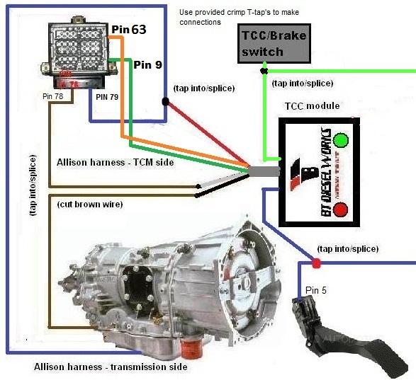
3 2. NOTE: BE SURE TO DOUBLE CHECK THAT MOUNTING OF MAIN CONTROL BOX AND ASSOCIATED WIRING DOES NOT INTERFERE WITH ACCELERATOR/BRAKE PEDAL MOVEMENT OR STEERING COLUMN MOVEMENT. ALSO USE EXTREME CAUTION AROUND ANY YELLOW/ORANGE COLORED CONNECTORS, AS THESE ARE AIRBAG SYSTEM RELATED CONNECTORS AND WIRING. 3. Drill hole in firewall using the plow-package blank/cutout as a reference. I find a step-bit works best for this. 4. Route the long gray wire through the firewall into the engine bay. Secure the gray wire along the firewall and along the fender so that the wire ends up at the TCM harness/connectors on the radiator shroud. NOTE: BE SURE TO SECURE GRAY WIRE OUT OF THE WAY OF ANY HOT MANIFOLDS, MOVING PARTS, OR ANYTHING ELSE THAT COULD DAMAGE THE WIRE. 5. Disconnect both batteries 6. Remove TCM and unplug the 80-pin connector 7. Unwrap electrical tape to expose a portion of the TCM wiring harness 8. Locate the brown wire that terminates at Pin #78 in the 80-pin TCM connector 9. Cut wire, leaving enough slack to splice in wires from the TCC-controller box 10. Strip ~1/2 of insulation off of each end of the brown wire. 11. Connect the TCM-side of the brown wire to the WHITE wire coming from the TCCcontroller box. Connect the TRANSMISSION-side of the brown wire to the BLACK wire coming from the TCC-controller box. SEE DIAGRAM BELOW FOR DETAIL. You can use the included butt-splice connectors, or soldering and heat-shrink tubing. 12. Locate the DARK-BLUE wire that terminates at Pin #79 in the 80-pin TCM connector. DO NOT CUT the wire; you are only splicing/tapping into it ( T ). Using a provided T-tap connector in the extra-parts Ziploc bag, securely crimp the T-tap into the dark blue wire. Connect the spade terminal (RED wire coming from the TCC-controller) to the T-tap. 13. Locate PINK/WHITE-STRIPE wire going to pin 63 of the TCM connector. DO NOT CUT THIS WIRE. You are only splicing/tapping into it ( T ). Using the provided T-tap connector, securely crimp the T-tap onto the red/black-stripe wire. Connect the spade terminal from the ORANGE (power supply) wire on the lockup controller harness to the T- tap. Alternatively, you can solder this connection (recommended) 14. Locate the BLACK/WHITE-STRIPE wire going to pin 9 of the TCM connector. DO NOT CUT THIS WIRE. You are only splicing/tapping into it ( T ). Using the provided T-tap connector, securely crimp the T-tap onto the red/black-stripe wire. Connect the spade terminal from the GREEN (ground) wire on the lockup controller harness to the T-tap. Alternatively, you can solder this connection (recommended) 15. Carefully check all connections and re-assemble the TCM connector. 3
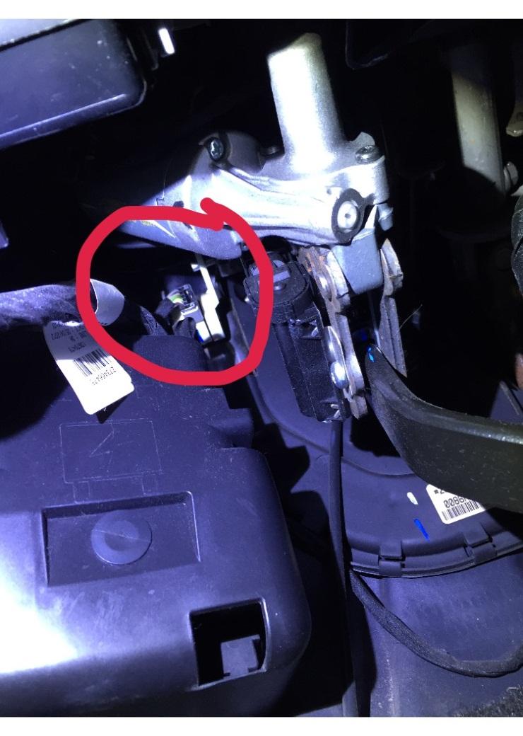
4 16. Locate the LIGHT GREEN wire that terminates at the brake pedal position sensor. The sensor is white and is under the dash mounted on the brake pedal. Using a provided T- tap connector in the extra-parts Ziploc bag, securely crimp the T-tap into the LIGHT GREEN brake-pedal switch wire. Connect the TCC-controller LIGHT GREEN-wire spade terminal to the T-tap. SEE DIAGRAM BELOW FOR DETAIL. 17. Disconnect the connector on the accelerator pedal position sensor. There is a CPA-clip on there that has to first be removed with a small screwdriver before the connector will be able to be unclipped. 18. Locate the DARK BLUE wire on the accelerator pedal connector harness. This dark blue wire terminates at Pin 5 on the accelerator pedal connector. 19. Using a provided T-tap connector in the extra-parts Ziploc bag, securely crimp the T-tap into the DARK BLUE wire on the accelerator pedal harness. Connect the TCC-controller DARK-BLUE wire spade terminal to the T-tap. SEE DIAGRAM BELOW FOR DETAIL. Reconnect the accelerator pedal position connector and replace the CPA-clip. 20. Decide where you want to route the remote control wiring, route the cable, and plug the remote control into the RJ11 plug on the lockup controller box. 21. Carefully route wiring and re-tape/secure wires so they do not interfere with proper accelerator pedal operation. Press the accelerator pedal and brake pedal to the floor several times to verify that no wires are snagged or chaffing. 22. Secure all wires and tape each connection/splice individually with good-quality electrical tape, or heat-shrink tubing. 23. Triple check all connections and be sure no wires are exposed We will NOT be responsible for damaged TCM s, wiring, f-trim solenoids, or lockup-controllers due to miswiring or loose connections!!! 24. Re-wrap TCM wiring harness in electrical tape and/or wire loom and secure TCCcontroller box wiring harness 25. Plug the TCM back in and replace the TCM mount, again checking for pinched wires. 26. Reconnect batteries 27. NOTE: BRAKE PEDAL POSITION SENSOR MUST BE LEARNED BEFORE THE CONTROLLER WILL BE ALLOWED TO WORK. IF YOU TURN THE KEY ON AND THE LIGHT ON THE CONTROLLER BLINKS RED, THE BRAKE PEDAL SENSOR HAS NOT BEEN LEARNED. FOLLOW THE INSTRUCTIONS BELOW 28. Start with the key OFF. BE SURE YOUR FOOT IS OFF OF THE BRAKE PEDAL! 29. Press and hold the BLUE button on the remote control 30. While still holding the BLUE button on the remote control, turn the key ON. Make sure your foot is still not touching the brake pedal! 4
5 31. The light on the controller will begin to blink blue. When it starts blinking blue, you can release the blue button. 32. The light will continue to blink blue for seconds while the module relearns the brake pedal sensor. Make sure you DO NOT TOUCH the brake pedal during this learn sequence. 33. When the light stops blinking, the learn procedure is complete. Turn the key OFF and wait seconds. 34. To verify that the pedal was learned successfully, turn the key on, engine off. Press the GREEN force-lock button. The light should turn green. Now press the brake pedal, and the light should turn off. 35. Read the following Operating Instructions first and then take the truck for a test drive and double-check for proper TCC-unlock switch operation. Remember if the truck is cold, it will take ~15 minutes of driving before the TCM will allow TCC lockup, so be sure the transmission temperature gauge has moved off the 100* mark before testing the switch. -Whenever the brake pedal is pressed, the module will suspend all activity and return TCC control to factory default. This is a necessary safety feature. If the module appears to have frozen, the buttons do not do anything, and/or the LED will not light up, first check the purple brake pedal signal wire. The wire should have +12v when the brake pedal is released, and should drop to 0v when brake pedal is applied. -Once the transmission temperature is above ~100*, TCC lockup is available and you will be able to lock or unlock it manually at anytime without limping the transmission or setting any DTC s. -The remote control module has three momentary pushbuttons for TCC control, green, red, and blue, as well as a tri-color LED status indicator light. -When the LED is BRIGHT GREEN, the TCC is in force-lockup mode -When the LED is RED, the TCC is in force-unlock mode -When the LED is BLUE, the TCC controller is in automatic standby mode -MANUAL MODE OPERATION: When the LED is dim/soft green, the module is operating in stock manual/standby mode, and the TCC is operating normally/automatically just like it would from the factory. -When the RED button is pushed, the module will force the TCC to unlock, regardless of its current state/status. IE, if you are driving around at lower speeds and the TCC is already unlocked, and you press the RED button, it will simply prevent the TCC from locking at all, even if you increase speed to where the TCM would normally lock it. If you are driving at higher speeds or higher throttle positions and the TCC is locked, pressing the RED button will immediately unlock it, regardless of what the TCM is telling it to do. -When the GREEN button is pushed, the module will for the TCC to immediately lock, regardless of its current state/status. IE, if you are driving around at lower speeds in non-tow/haul mode and 5
6 the TCC is unlocked, pushing the GREEN button will immediately force lockup regardless of speed or current gear. If you are driving at higher speeds and the TCC is already locked, pressing the GREEN button will simply prevent the TCC from unlocking in the future, even if you reduce your speed to the point where in normal/factory conditions, the TCM would unlock the TCC. - TO EXIT MANUAL TCC CONTROL MODE (either force-locked or force-unlocked), press the respective button once more and the TCC control will immediately return to factory mode, and it will relinquish TCC control back to the TCM. IE, if you are in force-unlock mode (LED is lit up red), simply press the force-unlock button (red button) one more time to return to factory-automaticmode. If you are currently in force-lock mode (LED is lit up green), simply press the force-lock button (green button) one more time to return to factory-automatic-mode, or just tap the brake pedal. -If you want to stay in manual mode, but change/swap between current TCC states (locked or unlocked), simply press the opposite respective button. IE, if you are in force-lock mode (LED is lit up green) and you want to transition right to force-unlock mode, simply press the force-unlock button (red button), and the TCC will immediately unlock and the LED will turn red. To relock from the force-unlock mode, simply press the green button again and the LED will turn back to green. -In summary, you do not have to return to factory-automatic mode each time you want to switch between force-locked and force-unlocked. You have full authority at all times and can change between modes at will. As said before, to return to factory at any time, push the respective button of whatever manual mode you are in at the current time, or press the brake pedal. -AUTOMATIC MODE OPERATION: The TCC controller has an automatic-lockup feature in addition to the standard manual TCC control. The parameters that must be met for the controller to automatically lock the torque converter (when armed in auto mode) are [throttle position above 95%] and [transmission in 2 nd, 3 rd, 4 th, 5 th, or 6 th gear]. So when you floor it from a stop, the TCC controller box will automatically lock the converter as soon as the transmission shifts into 2 nd gear. If you are in 2 nd gear or higher, the TCC controller box will automatically lock the converter when you go above 95% throttle. -To arm the automatic lockup mode, press the BLUE button on the handheld remote control. The status indicator LED will light up BLUE indicating that the module is armed in automatic mode and is standing-by to automatically lock the converter as soon as the brake pedal is released, 95% throttle is detected, and 2 nd gear is attained. -When both parameters are met (in auto mode) and the converter is locked up automatically, the LED will change to GREEN, indicating that the converter has been force-locked automatically. -When in auto mode and the converter has been force locked automatically, the TCC-controller box will exit and return the TCC control to factory configuration when throttle position drops below 50%, the transmission downshifts to 1 st gear, or the brake pedal is pressed. -When in auto-lock mode (at 100% throttle), you can still press the RED force-unlock button at any time to force the converter to unlock at any time, regardless of throttle position and current gear. When you are in AUTO mode, you do not lose the ability to force-unlock the converter after it has been locked automatically due to 95% throttle. When the TCC controller box is armed in auto, the force-unlock and force-lock buttons are disabled. 6
7 -To return to normal manual TCC operation and re-enable the on-demand force lock/unlock buttons, press the blue auto mode button to exit auto mode. The status indicator LED will turn off, indicating auto mode has been canceled and it is returning to normal standby operation. AUTO MODE TIME DELAY PROGRAMMING INSTRUCTIONS Lockup controller modules with software version and later have the ability to custom program a time delay before force-lockup will occur when in automatic mode. Normally, when in AUTO mode, as soon as the throttle is at 100% and the truck shifts into 2 nd gear, the module will immediately force-lock the converter automatically. However, sometimes with custom converters or bigger turbochargers, the module can force lockup to happen too soon, not allowing the turbo to become fully spooled. When this happens, the truck can bog down and lose acceleration. If you find that lockup is happening too soon when the controller is in AUTO mode, you can set a 0-6 second time-delay that the controller will wait before going into forcelockup mode. For example, if you set the time delay for 3 seconds, the controller will look for 100% throttle and 2 nd gear, and as soon as those two conditions are met, the controller will wait an additional 2 seconds before force-locking the converter. 1. Begin with key OFF 2. Press and hold down both the red and green buttons on the remote control 3. While still holding the red and green buttons, turn the key ON (do not start the truck) 4. The remote light will blink red/blue quickly, indicating programming mode is active 5. Once the light is blinking red/blue, release the red and green buttons 6. Press the blue button once (just momentarily, no need to hold it) 7. The light will turn a solid green, indicating the delay is "zero seconds" 8. Press the blue button again (just momentarily) 9. The light will blink green once, and then go back to solid green. That one blink indicates the delay is set for "one second" 10. To set the delay for two seconds, press the blue button again. Then the light will blink green twice and go back to solid green. The two blinks indicates the delay has been set for "two seconds" 11. Press the blue button again for 3 seconds, then 4 seconds, then 5 seconds, then 6 seconds, etc... The delay can be set anywhere from 0 to 6 seconds. 6 seconds is the max delay. Once the desired delay has been set (IE, the light blinks the desired amount of times, and then goes back to solid green), just turn the key off, wait 10 seconds, and turn the key on again. The setting is now saved permanently (IE, even if the module is disconnected from the truck or battery power is disconnected, the time-delay setting is still saved), or until you re-enter programming mode to change it again. 7
8 You can reprogram it as many times as you want, to set the delay differently, just follow the steps all over again. If you accidentally go "past" the desired setting (IE, you want to set it for 4 seconds, but accidentally hit the blue button a 5th time and the light blinks 5 times), just turn the key off, wait 10 seconds, and start the programming process over again. REGARDLESS OF CURRENT MODE/STATUS, PRESSING THE BRAKE PEDAL WILL ALWAYS OVERRIDE THE MODULE AND RETURN THE TCC CONTROL/OPERATION TO FACTORY. Anytime your foot is on the brake pedal, all force lock/unlock commands are ignored. This is a safety feature for obvious reasons. -IMPORTANT SAFETY NOTE: TRUCKS WITH THE ALLISON 6-SPEED HAVE THE ABILITY TO ALLOW MANUAL LOCKUP IN FIRST GEAR. So if you are idling along in a parking lot in first gear with your foot off the brake, and you press the green force lock button, the converter will lock and the truck will surge forward. As always though, a tap on the brake pedal will return everything to normal. -NOTE: The TCC control module does have a limited duty cycle; try not to run with the converter forced unlocked or force locked for an excessive amount of time. The force lock/unlock feature is only recommended to be used during racing/pulling. This is generally never a problem because sled pulls and drag races are far shorter than this time. There is an automatic thermal-overload protection built into the controller for safety that will prevent you from accidentally leaving the converter force-locked/force-unlocked. If the module is left in force-lock or force-unlock for longer than 30- seconds, the module will go into thermal-overload protection mode. TCC operation will be immediately returned to factory-stock and the LED will rapidly flash BLUE/RED for ~15 seconds, indicating that the duty-cycle has been exceeded. During this 30-second cool-down period, all force-lock and force-unlock commands will be ignored. After 15 seconds, the LED will stop flashing, and the module will automatically reboot/reset and return to normal operation. Also, under rare circumstances, repeated locking and unlocking with the module, or force-locking the converter at very low speeds and engine RPM s has the slight potential to set a TCC stuck-on DTC. Any further questions or if you ever have problems with the Allison TCC lockup/unlock switch module, feel free to PM me, me at BTDieselWorks@gmail.com, Thanks again, Ben Tyler, BT DieselWorks, LLC. 8
9 9
10 10
Allison Lockup Controller
 Allison Lockup Controller Installation instructions (6-speed LBZ/LMM, v6.x.x) By: BT DieselWorks, LLC. First of all, thank-you for purchasing the BT DieselWorks 2 nd generation Allison TCC lockup/unlock
LightSaver. Installation instructions, Classic GMT-800 GM truck/suv. By: BT DieselWorks, LLC. 12/2012
 LightSaver Installation instructions, 2001-2002 Classic GMT-800 GM truck/suv By: BT DieselWorks, LLC. 12/2012 First of all, thank-you for purchasing the BT DieselWorks LightSaver smart headlight control
Digital DSP-5 switch
 Digital DSP-5 switch Installation instructions, 2001-2004 LB7 Duramax By: BT DieselWorks, LLC. 5/2015 Thank you for purchasing the BT DieselWorks digital DSP-5 switch! The original digital/electronic DSP-5
GDP LB7 Duramax Digital Switch Installation. Step 1 Disconnect batteries.
 page 1 This instruction manual covers installation of the gauge pod mount DSP/SOTF switch for 2001-2004 LB7 classic/gmt-800 trucks only. DISCLAIMER: Tuning, LLC will not be held responsible for any personal,
Allison Lockup Controller
 19 February 2018 1031311/1031312/1031313 Allison Transmission Lockup and Pressure Module (I-00413) 1 Allison Lockup Controller Transmission Lockup and Pressure Controller 1031311 1031312 1031313 2001-2010
Installation Tips for your Crimestopper/ProStart Remote Start system (add-on for GM vehicles) v1.02 updated 1/16/2013
 v1.02 updated 1/16/2013") Installation Tips for your Crimestopper/ProStart Remote Start system (add-on for GM vehicles) v1.02 updated 1/16/2013 Thank you for purchasing your remote start from MyPushcart.com - an industry leader
Installation Tips for your Crimestopper/ProStart Remote Start system (add-on for GM vehicles) v1.02 updated 1/16/2013 Thank you for purchasing your remote start from MyPushcart.com - an industry leader
Automotive Application ET01 Software Revision A 12/06
 Automotive Application ET01 Software Revision A 12/06 INTRODUCTION... 2 FUNCTIONAL DESCRIPTION... 3 INSTALLATION... 4 COMPONENT PLACEMENT... 4 PLUMBING AND WIRING... 5 MSBC OPERATION (ET-01)... 14 TIMED
TranZformer 2 nd Gen Shift Kit Installation
 TranZformer 2 nd Gen Shift Kit Installation For Firmware Version 2.0.0-061214 The TranZformer Shift Kit is an electronic shift enhancer for 2011-2014 Dodge Charger and Chrysler 300 vehicles. The TranZformer
WOT Box Installation Instructions VW / Audi
 Connector Pinout Pin Color AWG Name WOT Box Installation Instructions VW / Audi Description 1 Yellow 18 RPM Connect to Fuel Injector Drive Signal or Ignition Control Signal (varies by car model) 2 Black
Installation Tips for your Add-on Remote Start (for GM vehicles with INTSL Install 2) v3.2 Updated 11/12/2012
 v3.2 Updated 11/12/2012") Installation Tips for your Add-on Remote Start (for GM vehicles with INTSL Install 2) v3.2 Updated 11/12/2012 Thank you for purchasing your remote start from MyPushcart.com - an industry leader in providing
Installation Tips for your Add-on Remote Start (for GM vehicles with INTSL Install 2) v3.2 Updated 11/12/2012 Thank you for purchasing your remote start from MyPushcart.com - an industry leader in providing
TIP SHEET T0937. Installation Tips For RS00/PS00 + ADS-TBSL-PL + SPDT
 Installation Tips For RS00/PS00 + ADS-TBSL-PL + SPDT TIP SHEET T0937 Thank you for purchasing your remote start from MyPushcart.com - an industry leader in providing remote starts to do-it-yourself installers
Installation Tips for RS4/RS7 + EVO-ALL (NIS 3.b)
") Installation Tips for RS4/RS7 + EVO-ALL (NIS 3.b) TIP SHEET T3092 + T3102 FOR: NISSAN ( 08-14 Frontier), ( 08-12 Pathfinder), & ( 08-12 Xterra) Thank you for purchasing your remote start from MyPushcart.com
Installation Tips for RS4/RS7 + EVO-ALL (NIS 3.b) TIP SHEET T3092 + T3102 FOR: NISSAN ( 08-14 Frontier), ( 08-12 Pathfinder), & ( 08-12 Xterra) Thank you for purchasing your remote start from MyPushcart.com
Read the entire installation manual. There are several safety tips there that you need to know before you start
 Installation Tips for RS4 + INTSL (2) TIP SHEET T0749 Buick Century: 2000-2005 Buick LeSabre: 2000-2005 Buick Park Avenue: 1999-2005 Buick Ranier: 2004-2007 Cadillac Escalade: 2003-2007 Chevrolet Avalanche:
Installation Tips for RS4/RS7 + EVO-ALL (NIS 3.c) + 2 diodes
 + 2 diodes") Installation Tips for RS4/RS7 + EVO-ALL (NIS 3.c) + 2 diodes TIP SHEET T3093 + T3103 FOR: NISSAN ( 09-14 Cube), ( 11-14 Juke), & ( 07-11 Versa) automatic, regular key vehicles Thank you for purchasing
Installation Tips for RS4/RS7 + EVO-ALL (NIS 3.c) + 2 diodes TIP SHEET T3093 + T3103 FOR: NISSAN ( 09-14 Cube), ( 11-14 Juke), & ( 07-11 Versa) automatic, regular key vehicles Thank you for purchasing
Installation Tips - (Crimestopper RS1/RS2) & (Fortin EVO-ALL 5): *regular key & automatic transmission only*
 & (Fortin EVO-ALL 5): *regular key & automatic transmission only*") Installation Tips - (Crimestopper RS1/RS2) & (Fortin EVO-ALL 5): TIP SHEET T3385f, T3413f *regular key & automatic transmission only* Thank you for purchasing your remote start from MyPushcart.com - an
Installation Tips - (Crimestopper RS1/RS2) & (Fortin EVO-ALL 5): TIP SHEET T3385f, T3413f *regular key & automatic transmission only* Thank you for purchasing your remote start from MyPushcart.com - an
Installation Manual v1.6: Dodge 68RFE Automatic Transmission. Please read all instructions before the installation of the ATS Co-Pilot
 Installation Manual v1.6: 2007.5-09 Dodge 68RFE Automatic Transmission Please read all instructions before the installation of the ATS Co-Pilot Thank you for purchasing the ATS Co-Pilot transmission management
Installation Tips for your Remote Start/Keyless Entry (for Ford Vehicles) v3.3 Updated 1/13/2013
 v3.3 Updated 1/13/2013") Installation Tips for your Remote Start/Keyless Entry (for Ford Vehicles) v3.3 Updated 1/13/2013 Thank you for purchasing your remote start from MyPushcart.com - an industry leader in providing remote
Installation Tips for your Remote Start/Keyless Entry (for Ford Vehicles) v3.3 Updated 1/13/2013 Thank you for purchasing your remote start from MyPushcart.com - an industry leader in providing remote
Installation Tips - (Crimestopper RS00) & (Fortin EVO-ALL) For:
 & (Fortin EVO-ALL) For:") Installation Tips - (Crimestopper RS00) & (Fortin EVO-ALL) For: TIP SHEET T3612-1a Acura TL 2004-2006 Honda Accord (Gas) 2003-2007 Acura TSX 2004-2008 Honda Accord (Hybrid) 2005-2007 Honda Ridgeline 2006-2013
Installation Tips - (Crimestopper RS00) & (Fortin EVO-ALL) For: TIP SHEET T3612-1a Acura TL 2004-2006 Honda Accord (Gas) 2003-2007 Acura TSX 2004-2008 Honda Accord (Hybrid) 2005-2007 Honda Ridgeline 2006-2013
Aftermarket Interface Module
 An ISO 9001:2008 Registered Company Aftermarket Interface Module (2015-2018 Ford Transit) AIM514-B High Side Solenoid type Coolant Valve Control AIM515-B Motor Reversing type Coolant Valve Control Introduction
Installation Tips Crimestopper/ProStart Remote Start system + PLJX + DLRM + SPDT (for GM vehicles) T0760 v1.1 updated 2/5/14
 T0760 v1.1 updated 2/5/14") Installation Tips Crimestopper/ProStart Remote Start system + PLJX + DLRM + SPDT (for GM vehicles) T0760 v1.1 updated 2/5/14 Thank you for purchasing your remote start from MyPushcart.com - an industry
Installation Tips Crimestopper/ProStart Remote Start system + PLJX + DLRM + SPDT (for GM vehicles) T0760 v1.1 updated 2/5/14 Thank you for purchasing your remote start from MyPushcart.com - an industry
Installation Tips for your Remote Start system (for RS4LX>GMBP for GM vehicles)
") Installation Tips for your Remote Start system (for RS4LX>GMBP for GM vehicles) Thank you for purchasing your remote start from MyPushcart.com - an industry leader in providing remote starts to doit-yourself
Installation Tips for your Remote Start system (for RS4LX>GMBP for GM vehicles) Thank you for purchasing your remote start from MyPushcart.com - an industry leader in providing remote starts to doit-yourself
GDP LBZ Duramax Digital Switch Installation TUNING. Step 1 Unbolt the OBD2 plug.
 page 1 This instruction manual covers installation of the gauge pod mount DSP/SOTF switch for 2006-2007 LBZ classic/gmt-800 trucks only. DISCLAIMER: Tuning, LLC will not be held responsible for any personal,
TIP SHEET T2352, T3396. Installation Tips for RS1 + EVO-ALL 1-BUTTON REMOTE STARTER FOR: Acura RDX PUSH-TO-START / AUTOMATIC
 Installation Tips for RS1 + EVO-ALL 1-BUTTON REMOTE STARTER FOR: Acura RDX 2013-2015 PUSH-TO-START / AUTOMATIC TIP SHEET T2352, T3396 Thank you for purchasing your remote start from MyPushcart.com - an
Installation Tips for your Remote Start w/ Keyless Entry (Toyota Vehicles) v3.2 Updated 3/14/13
 v3.2 Updated 3/14/13") Installation Tips for your Remote Start w/ Keyless Entry (Toyota Vehicles) v3.2 Updated 3/14/13 Thank you for purchasing your remote start from MyPushcart.com an industry leader in providing remote starts
Installation Tips for your Remote Start w/ Keyless Entry (Toyota Vehicles) v3.2 Updated 3/14/13 Thank you for purchasing your remote start from MyPushcart.com an industry leader in providing remote starts
ECT Display Driver Installation for AP2 Module
 ECT Display Driver Installation for AP2 Module Overview The ECT Display Driver is a small module with a removable wire harness that mounts behind the driver's foot well cover. All wiring connections are
Installation Manual for Dodge 24V Cummins Version 3.1. Please read all instructions before the installation of the ATS Co-Pilot
 10/1/12 601-900-2218-INST Installation Manual for 1998.5-2002 Dodge 24V Cummins Version 3.1 Please read all instructions before the installation of the ATS Co-Pilot Thank you for purchasing the ATS Co-Pilot
Torque Convertor Control System
 1 BD AutoLoc Torque Convertor Control System Part# 1030390 Installation Manual for the following applications: BD Brakes for Dodge, Ford and Chevrolet Pac Brake for Dodge & Ford Jacobs E-Brake for 1994-98
TIP SHEET. Installation Tips for your RS IB-MUX / PKUMUX (D) + SPDT T1205 v1.2 4/3/14. 1 P a g e
 + SPDT T1205 v1.2 4/3/14. 1 P a g e") Installation Tips for your RS-150 + IB-MUX / PKUMUX (D) + SPDT T1205 v1.2 4/3/14 TIP SHEET Thank you for purchasing your remote start from MyPushcart.com - an industry leader in providing remote starts
Installation Tips for your RS-150 + IB-MUX / PKUMUX (D) + SPDT T1205 v1.2 4/3/14 TIP SHEET Thank you for purchasing your remote start from MyPushcart.com - an industry leader in providing remote starts
GTWY515, GTWY516* Fast Idle, Shift Interlock, I/O Ford Transit Introduction
 An ISO 9001:2015 Registered Company GTWY515, GTWY516* Fast Idle, Shift Interlock, I/O 2015-2019 Ford Transit Introduction The Gateway 515 and 516 are wheelchair lift safety interlocks which allows lift
Torque Convertor Control System
 22 September 2015 PN#1030395 TorqLoc (I-00208) 1 BD TorqLoc Torque Convertor Control System Part# 1030395 Installation Manual for the following applications: BD Brakes for Dodge, Ford and Chevrolet Pac
Installation Tips for your RS-1 + Honda-SL3 (1.b) Remote starter Honda: ( FIT), ( Pilot), ( Ridgeline) Acura: ( MDX)
 Remote starter Honda: ( FIT), ( Pilot), ( Ridgeline) Acura: ( MDX)") Installation Tips for your RS-1 + Honda-SL3 (1.b) Remote starter Honda: ( 06-08 FIT), ( 05-08 Pilot), ( 06-13 Ridgeline) Acura: ( 03-06 MDX) TIP SHEET T0777 Thank you for purchasing your remote start from
Installation Tips for your RS-1 + Honda-SL3 (1.b) Remote starter Honda: ( 06-08 FIT), ( 05-08 Pilot), ( 06-13 Ridgeline) Acura: ( 03-06 MDX) TIP SHEET T0777 Thank you for purchasing your remote start from
GDP LBZ Duramax Digital Switch Installation TUNING. Step 1 Unbolt the OBD2 plug.
 06-07 LBZ Duramax page 1 This instruction manual covers installation of the gauge pod mount DSP/SOTF switch for 2006-2007 LBZ classic/gmt-800 trucks only. DISCLAIMER: Tuning, LLC will not be held responsible
RS4-7/PS4-7 + (2) + SPDT T3015, T3053
 + SPDT T3015, T3053") TIP SHEET Installation Tips for your RS4-7/PS4-7 + Honda-SL3 (2) + SPDT T3015, T3053 v1.3 4/25/14 Honda: ( 98-02 Accord), ( 98-01 CRV), ( 98-04 Odyssey), ( 03-04 Pilot) Acura: ( 98-99 EL), ( 98-03 CL),
TIP SHEET Installation Tips for your RS4-7/PS4-7 + Honda-SL3 (2) + SPDT T3015, T3053 v1.3 4/25/14 Honda: ( 98-02 Accord), ( 98-01 CRV), ( 98-04 Odyssey), ( 03-04 Pilot) Acura: ( 98-99 EL), ( 98-03 CL),
High Idle Kit Dodge Cummins (24 valve) Dodge Cummins (with APPS on motor) PLEASE READ ALL INSTRUCTIONS BEFORE INSTALLATION
 Dodge Cummins (with APPS on motor) PLEASE READ ALL INSTRUCTIONS BEFORE INSTALLATION") U 6 May 2014 (1036620-27) 1998.5-2014 Dodge / GMC High Idle Kit (I-00321) 1 High Idle Kit 1036620 1998.5 2002 Dodge Cummins (24 valve) 2003-2004 Dodge Cummins (with APPS on motor) 1036621 2005-2006 Dodge
U 6 May 2014 (1036620-27) 1998.5-2014 Dodge / GMC High Idle Kit (I-00321) 1 High Idle Kit 1036620 1998.5 2002 Dodge Cummins (24 valve) 2003-2004 Dodge Cummins (with APPS on motor) 1036621 2005-2006 Dodge
Installation Instructions for the Plug & Play Remote Start Package (EVOCHR4)
") T6002 v1.1 02/2013 Installation Instructions for the Plug & Play Remote Start Package (EVOCHR4) For CHRYSLER Town & Country 2008-2012 Review the remote start installation manual for safety instructions!
T6002 v1.1 02/2013 Installation Instructions for the Plug & Play Remote Start Package (EVOCHR4) For CHRYSLER Town & Country 2008-2012 Review the remote start installation manual for safety instructions!
Installation Tips for your Crimestopper/ProStart Remote Start system (for GM vehicles) v1.01 updated 2/27/2012
 v1.01 updated 2/27/2012") Installation Tips for your Crimestopper/ProStart Remote Start system (for GM vehicles) v1.01 updated 2/27/2012 Thank you for purchasing your remote start from MyPushcart.com - an industry leader in providing
Installation Tips for your Crimestopper/ProStart Remote Start system (for GM vehicles) v1.01 updated 2/27/2012 Thank you for purchasing your remote start from MyPushcart.com - an industry leader in providing
TIP SHEET T0937. Installation Tips for RS00 + Passlock-sl2(4) + SPDT
 + SPDT") Installation Tips for RS00 + Passlock-sl2(4) + SPDT TIP SHEET T0937 Chevrolet (Astro 1998-2005) (Avalanche 2002-2006) (Blazer 1998-2005) (Express Van 1998-2007) (Impala 2000-2005) (Monte Carlo 2000-2005)
Installation Tips for RS00 + Passlock-sl2(4) + SPDT TIP SHEET T0937 Chevrolet (Astro 1998-2005) (Avalanche 2002-2006) (Blazer 1998-2005) (Express Van 1998-2007) (Impala 2000-2005) (Monte Carlo 2000-2005)
TIP SHEET Installation instructions for EVO-NIST1 + LC1
 TIP SHEET Installation instructions for EVO-NIST1 + LC1 T3108 NISSAN INFINITY CUBE 2009-2014 M37 2010-2013 JUKE 2011-2016 M56 2011-2013 QUEST 2011-2016 Q70 2014-2015 SENTRA 2013-2016 Q70L 2015 VERSA SEDAN
Installation Tips for your Remote Start/Keyless Entry (for Honda/Acura Vehicles) [EVO-ALL] v1.02 updated 9/13/2013
![Installation Tips for your Remote Start/Keyless Entry (for Honda/Acura Vehicles) [EVO-ALL] v1.02 updated 9/13/2013](/thumbs/87/96035180.jpg "Installation Tips for your Remote Start/Keyless Entry (for Honda/Acura Vehicles) [EVO-ALL] v1.02 updated 9/13/2013") Installation Tips for your Remote Start/Keyless Entry (for Honda/Acura Vehicles) [EVO-ALL] v1.02 updated 9/13/2013 Thank you for purchasing your remote start from MyPushcart.com - an industry leader in
Installation Tips for your Remote Start/Keyless Entry (for Honda/Acura Vehicles) [EVO-ALL] v1.02 updated 9/13/2013 Thank you for purchasing your remote start from MyPushcart.com - an industry leader in
TIP SHEET. Installation Tips for SP-404/SP EVO-ALL + SPDT Remote Start/Alarm T1642
 TIP SHEET Installation Tips for SP-404/SP-502 + EVO-ALL + SPDT Remote Start/Alarm T1642 Nissan Armada: 2008-2012 Nissan Cube: 2009-2012 Nissan Frontier: 2008-2012 Nissan Pathfinder: 2009-2012 Nissan Quest:
Installation Tips for your Remote Start system (for Toyota Camry & Prius C, ) Crimestopper RS0+ EVO-ALL T3468 rev#1.
 Crimestopper RS0+ EVO-ALL T3468 rev#1.") Installation Tips for your Remote Start system (for Toyota Camry & Prius C, 2012-2014) Crimestopper RS0+ EVO-ALL T3468 rev#1.1 1/22/2015 Thank you for purchasing your remote start from MyPushcart.com -
Installation Tips for your Remote Start system (for Toyota Camry & Prius C, 2012-2014) Crimestopper RS0+ EVO-ALL T3468 rev#1.1 1/22/2015 Thank you for purchasing your remote start from MyPushcart.com -
Step 1 Wiring your remote start. Installation Tips for your Remote Start system (for GM vehicles) V3.3 revised 9/12/2013
 V3.3 revised 9/12/2013") Installation Tips for your Remote Start system (for GM vehicles) V3.3 revised 9/12/2013 Thank you for purchasing your remote start from MyPushcart.com - an industry leader in providing remote starts to
Installation Tips for your Remote Start system (for GM vehicles) V3.3 revised 9/12/2013 Thank you for purchasing your remote start from MyPushcart.com - an industry leader in providing remote starts to
Installation Tips for your Remote Start/Keyless Entry (for Mazda Vehicles) v3.1 Updated 9/22/2012
 v3.1 Updated 9/22/2012") Installation Tips for your Remote Start/Keyless Entry (for Mazda Vehicles) v3.1 Updated 9/22/2012 Thank you for purchasing your remote start from MyPushcart.com - an industry leader in providing remote
Installation Tips for your Remote Start/Keyless Entry (for Mazda Vehicles) v3.1 Updated 9/22/2012 Thank you for purchasing your remote start from MyPushcart.com - an industry leader in providing remote
Installation Instructions for the Plug & Play Remote Start Package (EVOCHR5)
") T6018 v1.1 02/2013 Installation Instructions for the Plug & Play Remote Start Package (EVOCHR5) For DODGE Nitro 2007-2011 Review the remote start installation manual for safety instructions! Overview Your
T6018 v1.1 02/2013 Installation Instructions for the Plug & Play Remote Start Package (EVOCHR5) For DODGE Nitro 2007-2011 Review the remote start installation manual for safety instructions! Overview Your
RS4 / RS7 + (4) + SPDT
 + SPDT") TIP SHEET Installation Tips for RS4 / RS7 + Honda-SL3 (4) + SPDT + Diode x2 T0776, T0731 Honda: ( 08-12 Accord), ( 12-13 Civic), 12-13 CRV), ( 11-13 Odyssey), ( 09-13 Pilot) Acura: ( 09-13 TSX) Thank you
TIP SHEET Installation Tips for RS4 / RS7 + Honda-SL3 (4) + SPDT + Diode x2 T0776, T0731 Honda: ( 08-12 Accord), ( 12-13 Civic), 12-13 CRV), ( 11-13 Odyssey), ( 09-13 Pilot) Acura: ( 09-13 TSX) Thank you
12/05/2012 Lockup Co-Pilot Instructions INST. Installation Manual v1.6: Dodge 68RFE Automatic Transmission
 Installation Manual v1.6: 2007.5-09 Dodge 68RFE Automatic Transmission Please read all instructions before the installation of the ATS Co-Pilot Thank you for purchasing the ATS Co-Pilot transmission management
RS4/RS7 + + SPDT T0776,T0731
 TIP SHEET Installation Tips for your RS4/RS7 + Honda-SL3 (1.a) + SPDT T0776,T0731 Honda: ( 03-07 Accord),( 01-05 Civic),( 02-06 CRV),( 03-10 Element),( 05-10 Odyssey) Acura: ( 01-03 EL),( 02-06 RSX),(
6R / 5-BUTTON SERIES VEHICLE SECURITY SYSTEM
 6R / 5-BUTTON SERIES VEHICLE SECURITY SYSTEM Button 1 Button 2 Button 5 Button 3 Button 4 Standard Features: Two 5-Button Remote Transmitters Status indicator (LED) Valet / override switch Multi-tone siren
Installation Tips for RS1 + EVO-RIDE + SPDT. *(reglar key, automatic transmission vehicles ONLY)*
*") Installation Tips for RS1 + EVO-RIDE + SPDT TIP SHEET T1235 *(reglar key, automatic transmission vehicles ONLY)* Thank you for purchasing your remote start from MyPushcart.com - an industry leader in providing
Installation Tips for RS1 + EVO-RIDE + SPDT TIP SHEET T1235 *(reglar key, automatic transmission vehicles ONLY)* Thank you for purchasing your remote start from MyPushcart.com - an industry leader in providing
ED COPYRIGHT PROTECTE
 Tremec T56 / Magnum / TR-6060 Reverse Lockout Control Module Installation Instructions ***Make sure you read item #4 on next page (page 2) or you will very likely damage something. How It Works The electronic
Be sure to read item #4 or you will very likely damage something.
 Installation Instructions for 82513 Reverse Lock Out Module Magnum, TR6060 or T56 6-Speed Be sure to read item #4 or you will very likely damage something. How It Works The electronic module contains a
Installation Manual v1.0: Dodge 68RFE Automatic Transmission. Please read all instructions before the installation of the ATS Co-Pilot
 09/30/11 601-900-2356-INST Installation Manual v1.0: 2010-11 Dodge 68RFE Automatic Transmission Please read all instructions before the installation of the ATS Co-Pilot Thank you for purchasing the ATS
Vehicle Alarm System With Channel 2 Auxiliary Output Installation Instructions
 Model PRO 9842 Installation Manual Vehicle Alarm System With Channel 2 Auxiliary Output Installation Instructions This Unit Is Intended For Installation In Vehicles With 12 Volt Negative Ground Electrical
Remote Start Kit for GM Installation RS1/3/4/7 + ADS-DL Tip Sheet
 Remote Start Kit for GM Installation RS1/3/4/7 + ADS-DL Tip Sheet rev 1.4 12/16/2013 Thank you for purchasing your remote start from MyPushcart.com - an industry leader in providing remote starts to do-it-yourself
Dfuser T/C Lock-Un Lock
 Dfuser T/C Lock-Un Lock Performance Diesel and more! For more information visit our website at: http://www.dfuser.com Page 1 of 6 User Guide This harness overrides and monitors Torque Converter (T/C) lockup
Installation Manual for Ford Power Stroke Version 1.4. Please read all instructions before the installation of the ATS Co-Pilot Module
 6/12/08 COPLT-F-99-02-INST Installation Manual for 1999-2003 Ford Power Stroke Version 1.4 Please read all instructions before the installation of the ATS Co-Pilot Module Thank you for purchasing the ATS
TIP SHEET EVO-CHRT6(d) STAND-ALONE ADD-ON REMOTE STARTER
 STAND-ALONE ADD-ON REMOTE STARTER") TIP SHEET EVO-CHRT6(d) STAND-ALONE ADD-ON REMOTE STARTER Txxxx -The EVO-ALL data and bypass interface module eliminates the need for many wiring connections associated with traditional remote starter installations
TIP SHEET EVO-CHRT6(d) STAND-ALONE ADD-ON REMOTE STARTER Txxxx -The EVO-ALL data and bypass interface module eliminates the need for many wiring connections associated with traditional remote starter installations
Installation Instructions
 Installation Instructions for EVS II Security and Keyless Entry Systems Note: It is recommended that this installation take place prior to rustproofing. The individual delivering the vehicle should review
ITCEMS950 Idle Timer Controller - Engine Monitor Shutdown Isuzu NPR 6.0L Gasoline Engine
 Introduction An ISO 9001:2008 Registered Company ITCEMS950 Idle Timer Controller - Engine Monitor Shutdown 2014-2016 Isuzu NPR 6.0L Gasoline Engine Contact InterMotive for additional vehicle applications
GDP LMM DURAMAX Digital Switch Installation TUNING. Step 1 Unbolt the OBD2 plug.
 07.5-10 LMM DURAMAX page 1 This instruction manual covers installation of the gauge pod mount DSP/SOTF switch for 2007.5-2010 LMM GMT-900 trucks only. DISCLAIMER: GDP Tuning, LLC will not be held responsible
Installation Tips for your Excalibur Remote Start (for Honda and Acura Vehicles) rev 11/28/2012
 rev 11/28/2012") Installation Tips for your Excalibur Remote Start (for Honda and Acura Vehicles) rev 11/28/2012 Thank you for purchasing your remote start from MyPushcart.com - an industry leader in providing remote starts
Installation Tips for your Excalibur Remote Start (for Honda and Acura Vehicles) rev 11/28/2012 Thank you for purchasing your remote start from MyPushcart.com - an industry leader in providing remote starts
GTWY605 Fast Idle, Shift Interlock, I/O Chevy 610 Van - 6.0L and 6.6L Engines Contact InterMotive for additional vehicle applications.
 An ISO 9001:2008 Registered Company GTWY605 Fast Idle, Shift Interlock, I/O 2009-2017 Chevy 610 Van - 6.0L and 6.6L Engines Contact InterMotive for additional vehicle applications. Introduction The Gateway
Speed For Sale LLC Website: Telephone: Location: 3100 Engineering
 Speed For Sale LLC Website: www.speedforsale.com/nissangtrparts Email: Sales@SpeedForSale.com Telephone: 770-777-4774 Location: 3100 Engineering Parkway Alpharetta, GA 30004 SpeedForSale.com s Installation
Installation Manual v3.0: Dodge Cummins. Please read all instructions before the installation of the ATS Co-Pilot
 Installation Manual v3.0: 2004-2005 Dodge Cummins Please read all instructions before the installation of the ATS Co-Pilot Thank you for purchasing the ATS Co-Pilot Torque converter/exhaust brake controller.
TranZformer 2 nd Gen Shift Kit Installation For Firmware Version
 TranZformer 2 nd Gen Shift Kit Installation For Firmware Version 2.2.0-110915 The TranZformer Shift Kit is an electronic shift enhancer for 2011-2014 Dodge Charger and Chrysler 300 vehicles. The TranZformer
TIP SHEET (EVO-FORT1) 80-bit Add-On Stand-Alone Remote Starter
 80-bit Add-On Stand-Alone Remote Starter") TIP SHEET (EVO-FORT1) 80-bit Add-On Stand-Alone Remote Starter T2380 *AUTOMATIC TRANSMISSION VEHICLES ONLY* PREPPING HARNESS VIDEO: https://www.youtube.com/watch?v=favdjn2gsxs INSTALL VIDEO: https://www.youtube.com/watch?v=9bp7ncnggya
TIP SHEET (EVO-FORT1) 80-bit Add-On Stand-Alone Remote Starter T2380 *AUTOMATIC TRANSMISSION VEHICLES ONLY* PREPPING HARNESS VIDEO: https://www.youtube.com/watch?v=favdjn2gsxs INSTALL VIDEO: https://www.youtube.com/watch?v=9bp7ncnggya
INSTRUCTIONS. #82044 Race Diesel Nitrous System
 INSTRUCTIONS #82044 Race Diesel Nitrous System Thank you for choosing ZEX products; we are proud to be your manufacturer of choice. Kit Parts List Description Qty. Description Qty. Nitrous Solenoid 2.088
Installation Manual for Dodge 12V Cummins Version 3.7. Please read all instructions before the installation of the ATS Co-Pilot
 Installation Manual for 1994-1998 Dodge 12V Cummins Version 3.7 Please read all instructions before the installation of the ATS Co-Pilot Thank you for purchasing the ATS Co-Pilot. This manual is to assist
INSTRUCTIONS. #82028 Diesel Nitrous System. Thank you for choosing ZEX products; we are proud to be your manufacturer of choice.
 1 INSTRUCTIONS #82028 Diesel Nitrous System Thank you for choosing ZEX products; we are proud to be your manufacturer of choice. Why our nitrous system is better: 2 Performance enthusiasts know the potential
Installation Instructions for Lingenfelter GM 2500 Suburban & Yukon XL Auxiliary Fan System (with AC clutch controlled fan output)
") Installation Instructions for Lingenfelter 2007-2013 GM 2500 Suburban & Yukon XL Auxiliary Fan System (with AC clutch controlled fan output) PN L300080607 Revision - 1.1 Lingenfelter Performance Engineering
Installation Instructions for Lingenfelter 2007-2013 GM 2500 Suburban & Yukon XL Auxiliary Fan System (with AC clutch controlled fan output) PN L300080607 Revision - 1.1 Lingenfelter Performance Engineering
INSTALLATION GUIDE Table of Contents
 CT-3100 Automatic transmission remote engine starter systems. What s included..2 INSTALLATION GUIDE Table of Contents Door lock toggle mode..... 4 Notice...2 Installation points to remember. 2 Features..2
NISSAN TRUCKS ELECTRONIC CRUISE CONTROL KIT AUTOMATIC & MANUAL TRANSMISSIONS PART NUMBER:
 General Applicability This cruise control was tested and verified on: 2008-2011 Nissan Frontier 2008-2011 Nissan Titan This cruise control may not function correctly on unverified vehicles. See www.rostra.com
C FORD F250 / F L POWERSTROKE DIESEL WITH AUTOMATIC TRANSMISSIONS ONLY
 EXHAUST BRAKES C40019 1999-2003 FORD F250 / F350 7.3L POWERSTROKE DIESEL WITH AUTOMATIC TRANSMISSIONS ONLY Getting Started Thank you and congratulations on your purchase of a Pacbrake exhaust retarder.
Installation Tips for your GMDLBP + Excalibur Remote Start system (for GM vehicles) v1.01 updated 10/09/13
 v1.01 updated 10/09/13") Installation Tips for your GMDLBP + Excalibur Remote Start system (for GM vehicles) v1.01 updated 10/09/13 Thank you for purchasing your remote start from MyPushcart.com - an industry leader in providing
Installation Tips for your GMDLBP + Excalibur Remote Start system (for GM vehicles) v1.01 updated 10/09/13 Thank you for purchasing your remote start from MyPushcart.com - an industry leader in providing
GTWY505 Fast Idle, Shift Interlock, I/O Ford E-Series
 An ISO 9001:2008 Registered Company GTWY505 Fast Idle, Shift Interlock, I/O 2009-2018 Ford E-Series Introduction The Gateway 505 is a wheelchair lift safety interlock which will only work with the ignition
Instruction Part #90577
 Phantom Key Push Button Ignition System Instruction Part #90577 For Installing: Part # s 55000, 55001, 55002, 55003, 55004, & 55005 Perfect Performance Products, LLC Painless Performance Products Division
Installation Instructions For #64320 Striker Turbo Timer Module
 2501 Ludelle Street Fort Worth, Texas 76105 817-244-6212 Phone 817-244-4024 Fax 888-350-6588 Sales 800-423-9696 Tech E-mail: painless@painlessperformance.com Web: www.painlessperformance.com Installation
2010 FORD TRANSIT ELECTRONIC CRUISE KIT Part Number:
 General Applicability Recommended Tools Item # Qty. Description 1. 250-2758 1 Cruise Control Module 2. 250-2760 1 Switch Harness 3. 250-2759 1 Main Wiring Harness 4. 250-2771 1 Pedal Interface Harness
TIP SHEET. Installation Tips for your RS OL-MDB-CH6 (1) (for Jeep vehicles) T1227 v1.0 3/19/14
 (for Jeep vehicles) T1227 v1.0 3/19/14") TIP SHEET Installation Tips for your RS-360 + OL-MDB-CH6 (1) (for Jeep vehicles) T1227 v1.0 3/19/14 Thank you for purchasing your remote start from MyPushcart.com - an industry leader in providing remote
TIP SHEET Installation Tips for your RS-360 + OL-MDB-CH6 (1) (for Jeep vehicles) T1227 v1.0 3/19/14 Thank you for purchasing your remote start from MyPushcart.com - an industry leader in providing remote
Installation Manual v2.5: Dodge 1994 to 2005 Ford 1994 to 2002-½ For Full Lock-Up And/Or Exhaust Brake Control
 Installation Manual v2.5: Dodge 1994 to 2005 Ford 1994 to 2002-½ For Full Lock-Up And/Or Exhaust Brake Control Please read all instructions before the installation of the ATS Commander Module Thank you
Installation Manual for VMAC Throttle Commander Throttle Control T500111
 Installation Manual for VMAC Throttle Commander Throttle Control T500111 2006-2007 Classic GMC CK2500-3500 6.0L Gasoline Engines 1.0 Preparation for Installation...4 1.1 Automatic Transmission Trucks...4
UNIVERSAL ELECTRA-STEER FOR 2 COLUMN 220w Plain w Polished w Plain w Polished
 UNIVERSAL ELECTRA-STEER FOR 2 COLUMN 220w Plain 8052810 220w Polished 8052610 360w Plain 8052780 360w Polished 8052760 Full refund will NOT be granted to any kits that are damaged, scratched, or altered
Installation Tips For Crimestopper RS7 + Passlock-sl2(4) + DLRM + SPDT
 + DLRM + SPDT") TIP SHEET T3628 Installation Tips For Crimestopper RS7 + Passlock-sl2(4) + DLRM + SPDT For Chevrolet: Astro 1998-2005, Avalanche 2002, Blazer 1998-2005, Cavalier 2000-2003, Express Van 1998-2005, S10 Pickup
TIP SHEET T3628 Installation Tips For Crimestopper RS7 + Passlock-sl2(4) + DLRM + SPDT For Chevrolet: Astro 1998-2005, Avalanche 2002, Blazer 1998-2005, Cavalier 2000-2003, Express Van 1998-2005, S10 Pickup
UNIVERSAL GAUGE WIRE HARNESS
 2650-1797-00 UNIVERSAL GAUGE WIRE HARNESS For Installing Auto Meter Electric Speedometer, Tachometer, And Short Sweep Electric Oil Pressure, Water Temperature, Fuel Level, and Volt Meter Gauges. This harness
Paddle Shifter User s Guide
 Paddle Shifter User s Guide Included Parts List: 1 - Receiver Module 1 - Receiver Module Harness (5 length) 1 - Paddle Shifter Module 1 - Paddle Shifter Module Harness 1 ½ Spacer 2 ¼ Spacer 1 User s Guide
Installation Instructions for Stand Alone Remote Starter (EVO-ALL-THAR-GM2) Firmware: 4.18, OPTION 15. T2362 Rev#1.2 last updated 10/15/13
 Firmware: 4.18, OPTION 15. T2362 Rev#1.2 last updated 10/15/13") Installation Instructions for Stand Alone Remote Starter (EVO-ALL-THAR-GM2) Firmware: 4.18, OPTION 15. T2362 Rev#1.2 last updated 10/15/13 -The new EVO-ALL interface module eliminates the need for a separate
Installation Instructions for Stand Alone Remote Starter (EVO-ALL-THAR-GM2) Firmware: 4.18, OPTION 15. T2362 Rev#1.2 last updated 10/15/13 -The new EVO-ALL interface module eliminates the need for a separate
TIP SHEET T0491. Installation Tips for your Excalibur RS Passlock-sl2(4) + DLRC + SPDT
 + DLRC + SPDT") TIP SHEET T0491 Installation Tips for your Excalibur RS-360 + Passlock-sl2(4) + DLRC + SPDT For Chevrolet: Astro 1998-2005, Avalanche 2002, Blazer 1998-2005, Cavalier 2000-2003, Express Van 1998-2005,
TIP SHEET T0491 Installation Tips for your Excalibur RS-360 + Passlock-sl2(4) + DLRC + SPDT For Chevrolet: Astro 1998-2005, Avalanche 2002, Blazer 1998-2005, Cavalier 2000-2003, Express Van 1998-2005,
UNISTEER Performance Products UNIVERSAL HOT ROD ELECTRA-STEER KIT
 UNISTEER Performance Products UNIVERSAL HOT ROD ELECTRA-STEER KIT 8051500 BEFORE YOU START PLEASE READ! Designing steering systems requires an understanding of steering function and design. If you are
Generation III Stand Alone Engine Harness
 78 Rattler Curry Road, Columbia, KY 42728 Phone 1-888-467-4491 sales@bp-automotive.com www.bp-automotive.com Generation III Stand Alone Engine Harness Installation Guide At BP Automotive we take pride
Ford Super Duty F-250, F and up
 Ford Super Duty F-250, F-350 2005 and up Installing Upfitter Switches by Richard L. Ray If you want to add a few aftermarket options to your new Ford Super Duty, Ford Motor Company makes things easy for
VS 315 DELUXE 4-CHANNEL MOTORCYCLE ALARM. Installation And Operation Manual MEGATRONIX CALIFORNIA, U.S.A. VS 315 1
 VS 315 DELUXE 4-CHANNEL MOTORCYCLE ALARM Installation And Operation Manual MEGATRONIX CALIFORNIA, U.S.A. VS 315 1 VS 315 2 INSTALLATION We recommend insulating all your soldered or crimped connections
V8 Gen. V Ford Mustang 2010 Update
 V8 Gen. V Ford Mustang 2010 Update There were several updates to the Ford Mustang in the 2010 model year. This document outlines the differences between the installation steps necessary for the 2010 Mustang
VTCM Installation Manual Table of Contents
 VTCM Installation Manual Table of Contents 1. Introduction:... 2 2. Disclaimer:... 2 3. Software / Drivers:... 2 a. Plugging in the controller:... 2 b. Install 4.0.NET Frame work:... 3 c. Install COM port
Trail Rocker Installation Instructions
 Trail Rocker Installation Instructions Manual #90580 For Installing Painless Part Numbers: 57000 and 57001 Painless Performance Products recommends you, the installer, read this installation manual from
Trail Rocker Installation Instructions
 Trail Rocker Installation Instructions Manual #90581 For Installing Painless Part Numbers: 57002 Painless Performance Products recommends you, the installer, read this installation manual from front to
*(reglar key vehicles ONLY)* Read the entire installation manual. There are several safety tips in there to know before you start
* Read the entire installation manual. There are several safety tips in there to know before you start") Installation Tips for RS4 + EVO-RIDE + SPDT TIP SHEET T2519 2009-2011 Ford Crown Victoria 2009-2012 Ford E-150 2009 Ford E-150 Econoline Club Wagon 2008-2010 Ford E-250 2010 Ford E-250 Econoline 2010 Ford
Installation Tips for RS4 + EVO-RIDE + SPDT TIP SHEET T2519 2009-2011 Ford Crown Victoria 2009-2012 Ford E-150 2009 Ford E-150 Econoline Club Wagon 2008-2010 Ford E-250 2010 Ford E-250 Econoline 2010 Ford
INSTALLATION MANUAL 601-S INFORMATION.) 8. REMOVE DOME LIGHT FUSE TO PRE- VENT BATTERY DRAIN.
 8. REMOVE DOME LIGHT FUSE TO PRE- VENT BATTERY DRAIN.") FOR NEGATIVE PARKING LIGHTS (MOST JAPANESE VEHICLES) FOR POSITIVE PARKING LIGHTS TRUNK RELEASE CIRCUIT DIAGRAM: OUT TO TRUNK 12V 2nd CHANNEL AUXILIARY (GRAY WIRE) 86 a 85 If the power trunk release requires
FOR NEGATIVE PARKING LIGHTS (MOST JAPANESE VEHICLES) FOR POSITIVE PARKING LIGHTS TRUNK RELEASE CIRCUIT DIAGRAM: OUT TO TRUNK 12V 2nd CHANNEL AUXILIARY (GRAY WIRE) 86 a 85 If the power trunk release requires
CP 634 DELUXE 4-CHANNEL KEYLESS ENTRY SYSTEM
 CP 634 DELUXE 4-CHANNEL KEYLESS ENTRY SYSTEM Installation And Operation Manual MEGATRONIX VAN NUYS, CA U.S.A. CP634 1 REMOTE CONTROL CONVENIENT SYSTEM INSTALLATION & OPERATION INSTRUCTIONS INTRODUCTION
Speed Sentinel II Programmable Road Speed Limiter
 An ISO 9001:2008 Registered Company Speed Sentinel II Programmable Road Speed Limiter SS501-A, SS501-AX Ford E Series 2005-2008 Ford F250-F550 Series 2008-2010 Ford Crown Victoria 2005-2008 Contact InterMotive
INSTALLATION INSTRUCTIONS FOR THE TOMAHAWK ELECTRIC REVERSE
 INSTALLATION INSTRUCTIONS FOR THE TOMAHAWK ELECTRIC REVERSE LAST UPDATED: April 2018 Thank you for choosing the Motor Trike Electric Reverse. We ask that you read the directions before you start and follow