Mechanical Power Presses
|
|
|
- Tyler Gray
- 5 years ago
- Views:
Transcription

1 Mechanical Power Presses 1
2 Mechanical power presses OSHA is the vertical regulation OSHA , general requirement; MPTA ANSI B for best safety practices 350,000 in the U.S. Full revolution clutch since 1857 Part revolution clutch since

3 Full Revolution Clutch 3
4 Part Revolution Clutch 4
5 Capacity 1/4 to bench-top to 5000 lbs. Smaller one likely to be Gap (C) Frame If inclinable, OBI, if not incliniable, OBS Larger ones tend to be straight side frame 4 columns from bed (bottom) to crown (top) Distinctive features: flywheel, crankshaft, clutch, brake, ram (slide) goes up and down 5

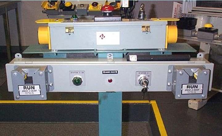
6 Part revolution bench top press 6
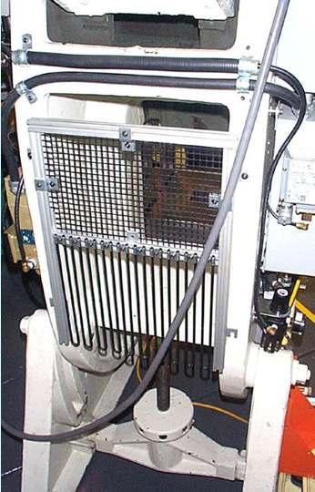
7 Bench top press (cont d) Light Curtain 7
8 Full vs. Part Revolution Clutch? Is an air line going to the clutch? If yes, it s a part revolution clutch press If no, then look for an operating rod coming down the side of machine to identify it as a full revolution clutch 8

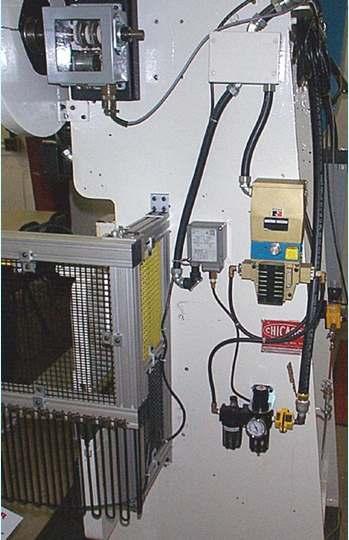
9 Part revolution clutch 9

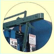
10 Full revolution clutch 10
11 Hydraulic Power Presses OSHA , general requirements, MPTA ANSI B for best safety practices 11

12 Hydraulic Press Light curtain Foot control 12
13 Power Press Brakes OSHA , general requirements, MPTA ANSI B for best safety practices 13

14 Press Brake 14
15 Modes of operation for mechanical power press Inch: Short hops of ram used for setup, maintenance, but not for production Single stroke: Often hand fed, sometimes with H.I.D. feeding. Safeguarding Devices most common Continuous: Makes many cycles without stopping using an automatic feed & coil stock. Sging: Guards most common 15
16 Modes of Operation, Control Selector inch, single stroke, continuous Emergency stop button 16
17 Primary operations Automatics or blankers Coil stock with automatic feeds Payoff reels or cradles to unwind Continuous mode 17
18 Secondary operations? Single-stroke mode of operation Manually fed - one at a time Often use Hands-in-Die Feeding Hand feeding tools are the BSP Cycle initiation can be hand or foot Ergonomic issues if high repetition 18
19 Types of mechanical presses Two general frame configurations C frame Used for maximum rated forces up 300 tons Similar to C clamp in appearance Three subcategories OBI (Open Back Inclinable) Gap Press (OBS) Horn Press 19

20 Open Back Inclinable Press Hand operated inclining mechanism on OBI. Turning hand crank rotates screw to tilt press back to desired position. 20

21 Open Back Stationery Press Flywheel is located at the rear of the press frame on front-to-back presses, eliminating obstruction around the die frame. 21

22 Horn Press 22
23 General frame configurations (cont d) Straight side frame Used on most presses that can develop a maximum rated tonnage of 20 tons or more Consist of bed with a four corner post arrangement called uprights. 23

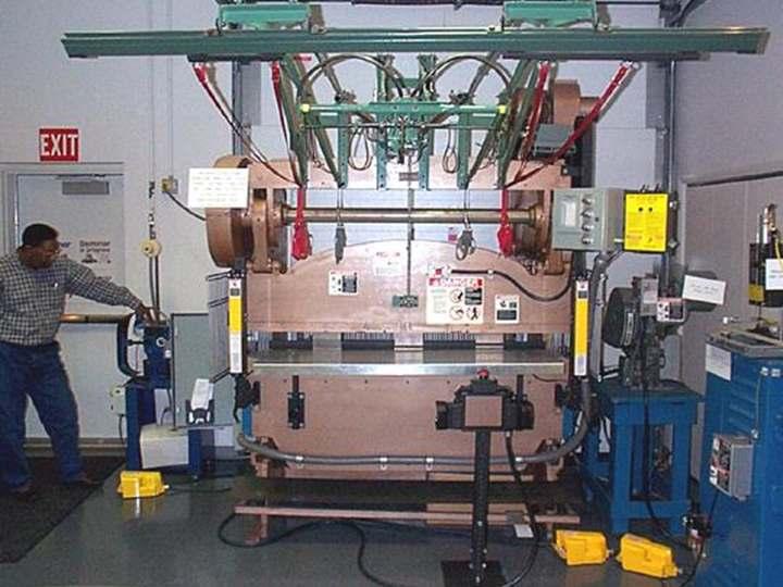
24 Part Revolution Straight-Side Press - Left Side View Main Drive Air Surge Drive Air Releasing Brake Lifting Lug Crown Dual Solenoid Valve Air Pressure Switch for Clutch/Brake Air Pressure Switch for Counterbalance Air Pressure-Gauge & Lubricator Assembly for Clutch/Brake Upright or Column Lubricator Operator s Station Side Guard Bed Filter-Regulator-Gauge for Die Cushion 24

25 Tie Rod Nut Tie Rod Crankshaft Air Counterbalance Belts Sheave Main Gear Flywheel Air Friction Clutch Connection (Pitman) Side Adjusting Mechanism Side (Ram) Gib Run Buttons Top-Stop Buttons Bolster Cover Rotating Limit Switch Assembly Knockout bracket Knockout Rod Knockout Bar Control panel with Starter and Disconnect Switch Emergency-Stop Button Straight Side- Front View 25
 Operator s Station Slide (Ram) Knockout Bar Side Barriers")
26 Full Revolution - Left Side View Motor Cam and Limit Switch Motor Starter Disconnect Switch Control Box Drag Brake Knockout Knockout Bracket Inclining Mechanism Frame (Body) Operator s Station Slide (Ram) Knockout Bar Side Barriers Leg 26
 Gib Air Cylinder (Solenoid Valve, & Filter-Regulator-Gauge and Lubricator Assembly Not Shown) Bed Leg Tie Rod Foot")
27 Full Revolution - Front View Belts Limit Switch Crankshaft Connection (Pitman) Lubricator Die Clamp Rear Barrier Bolster Leg Bolts Sheave Lifting Bolt Flywheel Clutch Area Cover Side Adjusting Screw Run Buttons (Two-Hand Trip) Gib Air Cylinder (Solenoid Valve, & Filter-Regulator-Gauge and Lubricator Assembly Not Shown) Bed Leg Tie Rod Foot Control 27
28 Types of mechanical power presses (cont d) Functional type Operating characteristics Full revolution clutch Part revolution clutch Electric motor is primary drive source Motor drives press flywheel, which generates energy that s applied by way of the crankshaft and ram to the lower dies. 28
29 Full revolution clutch Uses keys, pins, or jaws to engage crankshaft to flywheel Once engaged, clutch drags crankshaft through one complete revolution before it can be disengaged Uses friction brake that is always applied to hold slide stationery when clutch is not engaged Will not stop until it has completed one full stroke 29

30 Clutch Pin 30

31 Clutch pin 31

32 Clutch Pin 32

33 Jaw type Striking plate on flywheel Rotary air seal Sliding sleeve with multiple engaging jaws Direct-acting pneumatic chamber 33

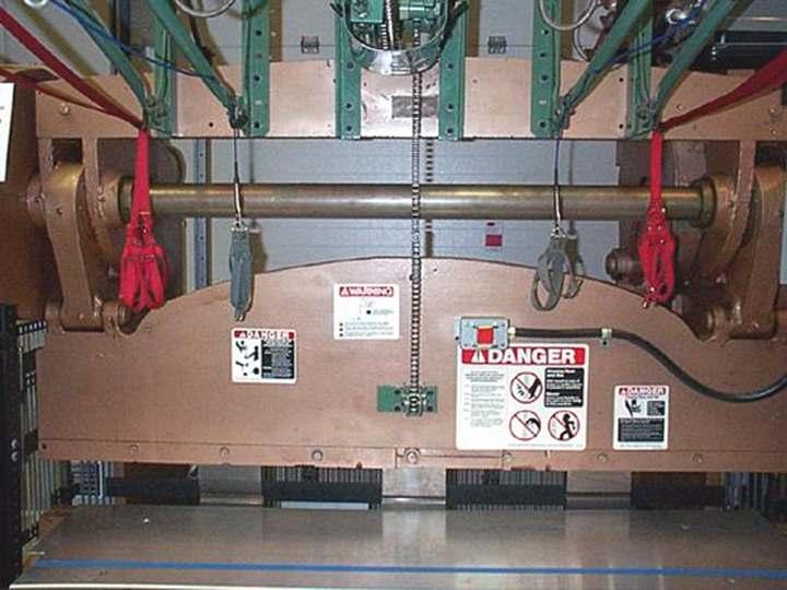
34 Friction Brake 34
35 Part revolution clutch Engaged and disengaged at any point in slide Engaged with air pressure/released with absence of air pressure A friction brake that is air released and spring applied is used to stop and hold slide in position when clutch is not engaged Can be stopped at any point in 35

36 Air line for clutch engagement. Engaged with air pressure, released with absence of air pressure. Part revolution clutch 36

37 Part revolution brake Air released and spring applied 37
38 Mechanical power presses and their controls - (full revolution clutch) Machines using full revolution clutches Will incorporate single stroke mechanism Single stroke mechanism dependent on spring action Springs will be compression type operating on a rod or guide within a hole or tube Designed to prevent interleaving of 38
39 Single stroke mechanism Compression spring operating on a rod or guided within a hole or tube. 39
40 Methods of initiating press cycle Foot pedals - treadle Protected to prevent unintended operation from falling or moving objects. Pad with nonslip contact area firmly attached to pedal Pedal return springs will be compression type If counterweights are provided, path of travel of weight will be enclosed Enclose the weight s path of travel to prevent interference with its movement 40

41 Foot treadle Canopy guard Removable foot pedal Treadle 41

42 Foot Control Protection from unintended objects Manufactures Specifications Compression type spring Applicable Safety Warnings 42
43 Hand operated levers Will be equipped with a spring latch on the operating lever to prevent premature and accidental tripping Operating levers, if provided are required for each operator, and require concurrent operation 43
44 Two-Hand trips Protected against unintentional operation Requires both hands, concurrent operation, and provided for all operators 44

45 Two-Hand Trips/Controls Note: Red stop button normally not present 45
46 Two-Hand Trips/Controls 46

47 Two-Hand Trip/Controls Prior Action Button Two Hand Control Top Stop Emergency Stop 47
48 Part revolution clutches Machines using part revolution clutches Clutch release and brake will be applied when external clutch engaging means is removed, deactivated or de-energized Stop control Red stop control, required at each station Top stop, if provided, will be yellow Stop control will override any other control 48
49 Part revolution clutches (cont d) Press stroking selector A means of selecting off, inch, single stroke and continuous will be available. Means capable of being supervised Inch Operation Designed to prevent exposure of worker s hands by: Requiring concurrent use of both hands Being a single control protected against accidental actuation Will not be used for production (ANSI) 49
50 Part revolution clutches (cont d) Multiple operating stations Control station for each operator capable of being supervised Continuous Will be supervised, and require prior action or decision by the operator in addition to the selection of the continuous mode Hand-foot selection If provided, selection method for foot control will be separate from stroking selector Will be supervised by employer 50
51 Part revolution clutches (cont d) Foot control Protected against unintentional operation Clutch/brake air valve failure Control of air-clutch machines will be designed to prevent significant increase in normal stopping time due to a failure within the operating valve mechanism, and to inhibit further operation if such failure does occur. 51
52 Part revolution clutches (cont d) Press drive motor interlock Clutch/brake control should not initiate the press stroke unless the drive motor is in the forward direction Engaging method failure Clutch/brake control will automatically deactivate in event of power failure or pressure supply for the clutch engaging means Reactivation will require restoration of normal supply and the use of the 52
53 Part revolution clutches (cont d) Air counterbalance supply Clutch/brake control will automatically deactivate in event of failure of the counterbalance air supply Reactivation of the clutch will require restoration of normal air supply and use of the tripping mechanism Turnover bar operation Selection of bar operation will be by means capable of being supervised by the employer 53
54 Part revolution clutches - control reliability When required, control system will be constructed so that a failure within the system does not prevent the normal stopping action from being applied to the press when required, but does prevent initiation of a successive stroke until the failure is detected Failure will be detectable by a simple test, or indicated by the control 54
55 Part revolution clutches - control reliability (cont d) Dual-air valves Air-filter regulator Air Pressure switch Rotating cam switch assembly 55

56 Dual-Air Valve Single-Air Valve 56
57 57

58 Rotating Cam Switch Assembly Belt Assembly Rotating Cam Switches 58
59 Part revolution clutches - brake monitoring Be constructed to automatically prevent the activation of a successive stroke if stopping time or braking distance deteriorates to a point where the safety distance being utilized does not meet the requirements Used with the Type B gate or movable barrier device, will be installed to detect slide top-stop 59

60 Solid State Diagnostic Display Panel 60
61 Part revolution clutches - brake monitoring (cont d) Be installed so indicates when performance of the braking system has deteriorated Be constructed and installed to monitor brake system performance on each stroke 61
62 Part revolution clutch - top stop overrun brake monitors Top stop brake monitor checks the crankshaft position at the end of each stroke, and will not let the operator initiate another stroke if the crankshaft is too far past top dead center. 62
63 Other safety requirements - electrical Control circuit All clutch/brake control circuits will incorporate features to minimize unintended stroke in event of control component failure Disconnects Main power disconnect capable of being locked only in the Off position Starters Protect against accidental operation Drive motor with a magnetic motor restart function 63
64 Other safety requirements - electrical (cont d) Transformer Used to reduce voltage of operator controls Ground Electrical circuits shall be protected against an accidental grounding 64

65 Disconnect switch capable of being locked in off position Motor starter control panel start/stop switch 65

66 Disconnect Switch, turns to locked position Solid control panel 66

67 Motor starter and fused disconnect switches MOTOR START SWITCH SWITCH TURNS TO LOCKED POSITION MOTOR START STOP CONTROL 67

68 Solid state control panel Light curtain switch Control selector Motor stop button 68
69 Other safety requirements (cont d) Counterbalance Air counterbalance system with adequate capacity that will hold slide and attachments Air controlling equipment Protected against foreign material and water entering pneumatic system Hydraulic equipment Maximum working pressure will not exceed working pressure rating of any components Pressure vessels Must meet ANSI/ASME code for pressure vessels, 1968 edition 69
70 Point of operation safeguarding - Two-Hand Trip Point of operation devices - will protect operator by Preventing and/or stopping normal stroking of the press if the operator s hands are placed I n the point of operation Preventing the operator from reaching into the point of operation, or withdrawing his hands if they are inadvertently located in the point of operation as the dies close 70
71 Point of operation safeguarding - Two-Hand Trip (cont d) Preventing the operator from reaching into the point of operation at all times Requiring application of both of the operator s hands to machine operating controls and locating such controls at a safe distance from the point of operation that the slide completes the downward travel or stops before the operator can reach 71
72 Point of operation safeguarding - Two-Hand Trip (cont d) Enclosing the point of operation before a press stroke can be initiated, and maintaining this closed condition until the motion of the slide has ceased Enclosing the point of operation before a press stroke can be initiated so as to prevent an operator from reaching into the point of operation prior to die closure or prior to cessation of slide motion during the downward stroke 72
73 Point of operation safeguarding - Two-Hand Trips Require use of both operator s hands Located at safe distance from P.O.O. Provided for each operator Require concurrent application Incorporate antirepeat feature Fixed so only a supervisor is capable of relocating the trips 73
74 Point of operation safeguarding - Two-Hand Trips (cont d) Incorporate antirepeat feature Fixed in position so only a supervisor is capable of relocating the trips Safety distance calculation Tm = 1/2 + 1 X Time necessary to one # of engaging complete points per revolution 74
75 Two-Hand controls - part revolution only Require use of both operator s hands Located a safe distance from P.O.O. Provided for each operator Require concurrent application Protected against unintentional operation Incorporate antirepeat feature 75
76 Two-Hand Controls Key Selector capable of being supervised Top Stop Emergency Stop Indicator Light 76
77 Two-Hand Controls - part revolution only (cont d) Fixed in position so only a supervisor is capable of relocating the controls Safety distance Ds = 63 inches/second x Ts; where Ds = minimum safety distance (inches) 63 inches/second = hand speed constant; and Ts = stopping time of the press measured at 77
78 Presence sensing device Device will be interlocked into control circuit to prevent or stop slide motion if the operator s hand or other part of his/her body is within the sensing field of the device during the downstroke of the press slide 78
79 Presence sensing device (cont d) May not be used on machines using full revolution clutches May not be used as a tripping means to initiate slide motion Will be constructed so failure within system does not prevent the normal stopping action from being applied to press when required, but does prevent initiation of a successive stroke until the failure is corrected Muting (bypassing) of protective function of 79 such device during the upstroke of press
80 Presence sensing device (cont d) Guards will be used to protect all areas of entry to the P.O.O. not protected by the presence sensing device Safety distance from sensing field to P.O.O. will be greater than the distance determined by the following formula: Ds = 63 inches/second X Ts where: Ds = minimum safety distance (inches) 63 inches/seconds = hand speed constant; and Ts = stopping time of the press measured at approximately 90 degree position of crankshaft rotation (seconds) 80

81 Light Curtain - Presence Sensing Device Features Receiver Transmitter * Meets industry standards * Self-checking circuitry * Strobe-light and weld flash immunity without increasing response time * Detects objects 1 or larger * Channel blanking * 50 max operating range Control box 20 Cables 81

82 Light Curtain - Flex Systems Applications Receivers Transmitters 82

83 Presence sensing device Control box Light curtain 83

84 Presence sensing device Top guard assembly Light curtain 84

85 Horizontal mounted light curtain Presence sensing devices light curtain Vertical mounted light curtain 85
86 Pullback s Device will include attachments for each operator s hands Attachments will be connected to and operated only by the press slide or upper die Attachments will be adjusted to prevent operator from reaching into P.O.O. A separate pull-out device will be provided for each operator 86

87 Arm-Type Pullback 87


88 Overhead Type Pullback 88

89 Two-Man Operation 89

90 Two-Man Operation Side Guard Panel Pullbacks Light Curtain 90

91 Wristlets and Cables 91


92 Point-of Operation Devices Protect Hands Ram Up - Die Open Ram Descending - Die Closing 92
 Ram Down - Die is")
93 Point-of-Operation Devices Protect Hands (cont d) Ram Down - Die is Closed 93
94 Pullbacks (cont d) Inspected, checked and adjusted at start of each operator s shift, following a new die setup, and when operators are changed Necessary maintenance, repair or both will be performed and completed before press is operated Records of adjustments, inspections and maintenance will be kept in accordance with paragraph (e) of this section Sweep device may not be used for pointof-operation safeguarding after December 94
95 Restraint Devices Device will include attachments for each operator s hands Attachments will be securely anchored and adjusted so that operator is restrained from reaching into P.O.O. Separate set of restraints will be provided for each operator if more than one operator is required on a press Records of adjustments, inspection and maintenance will be kept in accordance with paragraph (e) of this section 95

96 Two-person sliding restraint 96
97 Gates A gate or movable device will protect the operator as follows: Type A gate or movable barrier device will protect the operator as specified in paragraph (c)(3)(i)(f) Type B gate or movable barrier device will protect the operator as specified in paragraph (c)(3)(i)(g) 97
98 Guards Every point-of-operation guard will meet the following design, construction, application and adjustment requirements: Prevent entry of hands/fingers into P.O.O. by reaching through, over, under or around guard Conform to the maximum permissible openings of Table 0-10 Create no pinch point between guard and moving machine parts 98
99 Guards (cont d) Utilize fasteners not readily removable by the operator Exception: Electrical interlock switch Facilitate its inspection Offer maximum visibility of the point of operation consistent with the other requirements 99
100 Guards (cont d) A die enclosure guard will be attached to the die shoe or stripper in a fixed position Good for one particular press A fixed barrier guard will be secured to the frame of the press or to the bolster plate No openings 100
101 Guards (cont d) An interlocked press barrier guard will be attached to the press frame or bolster plates, and will be interlocked with the press clutch control The adjustable barrier guard will be securely attached to the press bed, bolster plate, or die shoe, and will be adjusted and operated in conformity with Table 0-10 A point-of-operation enclosure which does not meet the requirements of Table 0-10 will be used only in conjunction with P.O.O. devices 101

102 Front Guard Interlock switch 102

103 Side Guard Fixed Panel Adjustable guard 103

104 Barrier Guard Fixed panel in back of machine 104

105 Expanded metal lexan guarding materials Adjustable guarding sections 105

106 Various Guards 106

")
107 Various guards 107 (cont d)


108 Various guards (cont d) 108
109 Various guards (cont d) 109

110 Spring lift guard Mechanical motor springs Black square mesh Adjustable hairpins 110

111 Spring lift guard Air cylinders Linear bearing assembly Nonadjustable portion of panel with black mesh Adjustable hairpins Key-operated control station 111
112 Design, setting and feeding of dies Die setting Establish die setting procedures Provide and require use of hand tools for removing scrap pieces Scrap handling Provide means for handling scrap material Guide post hazard Hazard created by a guide post when separated from its bushing 112
113 Design, setting and feeding of dies (cont d) Unitized tooling Opening between top of the punch holder and face of the slide, or striking pad will be guarded Tonnage, stroke and weight designation All dies will be: Stamped with the tonnage and stroke requirements Stamped to indicate upper die weight Stamped to indicate complete die weight 113

114 Tonnage, stroke and weight designation Model number Tonnage Stroke 114
115 Tonnage, stroke and weight designation Model number Tonnage Stroke 115
116 Design, setting and feeding of dies (cont d) Die fastening Securely mount die to bolster plate and slide When clamp caps or setscrews are used in conjunction with punch stems, additional means of securing the upper shoes to the slide will be used Die handling Handling equipment attach points will be provided on all dies requiring mechanical handling 116
117 Design, setting and feeding of dies (cont d) Die setting Employer will establish a die setting procedure that will enhance compliance with paragraph (c) of this section Provide spring loaded turnover bars Provide die stops, or other means to prevent losing control of the die while setting or removing dies Provide and enforce the use of safety blocks Provide brushes, swabs, lubricating rolls, and automatic/manual pressure guns so 117

118 Spring loaded turnover bar Vinyl-coated yellow handle Made of high tensile steel Fully enclosed spring 118
119 Design, setting and feeding of dies (cont d) Inspection and maintenance records Periodic and regular inspections of all presses and safeguards Inspected and tested no less than weekly; clutch/brake, antirepeat, and single stroke mechanism Modifications Establish new or changed guidelines for care and use 119
120 Sample Press Inspection Report Parts Inspected OK Defective Condition Corrective Action Date Repaired Frame/Motor Flywheel/Gears Crankshaft Clutch/Brake Connection and slide adjusting screw Slide and Gibs Slide counterbalance Air/Electrical system Foot switch P.O.O. safeguarding Guards and presence sensing devices Pullbacks/Restraints A or B Gate/ Two Hand Trip or Control 120
121 Guide for inspecting mechanical power presses Frame Cracks, broken or loose parts Motor Clean, and lubricated Flywheel Rotates in correct direction, free running Gears Loose, broken/cracked teeth, excess noise? Crankshaft 121
122 Guide for inspecting mechanical power presses (cont d) Clutch Full revolution single stroke capability, loose or worn parts, weak or broken springs Part revolution Air or oil leaks, proper alignment, disengagement, stopping position, worn clutch lining, weak or broken springs Brake Linings worn, properly adjusted, does it stop slide quickly 122
123 Guide for inspecting mechanical power presses (cont d) Slide and gibs Face of slide parallel to bolster, proper gib clearance, any scoring Connection & slide adjusting screw Proper bearing and ball seat clearance, screw turns freely Slide counterbalance Spring type Proper adjustment, broken springs or loose nuts Pneumatic type Air leakage, proper pressure, loose connection to slide 123
124 Guide for inspecting mechanical power presses (cont d) Air system Proper air pressure, valve operation, pressure gauges, leaks Electrical system Can main power switch be locked only in off position, grounding, condition of wiring Foot switch Nonslip pad on contact area, shielded from accidental operation 124
125 Guide for inspecting mechanical power presses (cont d) Point-of-operation safeguarding Guard Barrier that prevents entry of operator s hands or fingers into point-of-operation area Presence sensing Reliable design and proper electrical tie-in to control Fixed at proper distance Pullback Enough or too muck pull on cables Is adjustment being made for change of operator, die, shift Records of inspection/maintenance 125
126 Guide for inspecting mechanical power presses (cont d) Point-of-operation-safeguarding A or B Gate Point of operation enclosed before press cycle can be initiated Restraint Adjusted so operator s fingers cannot reach into dies Securely anchored Adjusted for each operator Two-hand Trip or Control Shielded against unintended operation Concurrent antirepeat Fixed at proper safety distance from pinpoint 126
127 Design, setting and feeding of dies (cont d) Instructions to operators Training shall be provided for press operators Work area Adequate clearance between machines for movement of operator Ample room for cleaning, and material handling Floors kept in good condition 127
128 Design, setting and feeding of dies (cont d) Overloading Operate presses within manufacturer specifications Report of injuries Report injuries within 30 days 128

129 Bellows safety shield 129

130 Die set shields Bellows safety shield Bellows safety shield 130

131 Hand feeding and retrieving tools 131


132 Die safety block accessories Two-piece aluminum safety wedges Adjustable screw device 132
")

133 Die safety block accessories (cont d) Safety plug is disconnected. Press is inoperable. Block in use 133

134 Die safety block accessories (cont d) Electric safety plug is connected. Control circuit is made and press can be operated Block in storage 134

135 Die safety block accessories (cont d) Interlock must be interfaced into the control system so that when plug is pulled, power to the main drive motor is disconnected. 135

136 Die safety block accessories (cont d) Electrical power cut-off system Die safety block Wedges Die safety block holder 136
137 Types of Press brakes Press brakes are machines that have a long narrow bed and slide, usually supported by C form frames on the ends of the bed and slide Part revolution clutch - mechanical friction Part revolution clutch - air Hydraulic Hydra-Mechanical 137

138 Two-speed air-clutch press brake Light curtain on floor stands Custom control box Two operator stations Barriers 138

139 Hydraulic press brake Control box Light curtain Interface box Side guards and mounting brackets Foot switch 139

140 Hydramechanical press brake Control box Hydraulic valve Light curtain 140
141 141
142 142

143 Press brake Side shield Light curtain 143
144 Press brake Side shield Light curtain 144
145 Application of press brakes Press brakes are used to perform a variety of operations on sheet, plate, and other metals The primary application of a press brake is to bend sheet metal at an angle to form flanges, boxes, channels, etc. 145

146 Press brake bending metal 146
147 Safeguarding point of operation (guards) Barrier guards Adjustable guards Self-adjusting guards Interlock guards 147
148 Safeguarding point of operation (devices) Two-Hand controls Restraints/Pullbacks Presence sensing devices Gates 148
149 Safeguarding standards 29 CFR (a)(3)(ii) Section 5(a)(1) ANSI B
150 Danger Line Table 0-10 Table 0-10 Distance of opening from P.O.O. hazard Max width of opening Clearance Line M inimum Guarding Line Guarding must extend from some point on clearance line to some point on opening line Typical guard locations 1/2 to 1-1/2 1/4 1-/12/ to 2-1/2 3/8 2-1/2 to 3-1/2 1/2 3-1/2 to 5-1/2 5/8 5-1/2 to 6-1/2 3/4 6-1/2 to 7-1/2 7/8 7-1/2 to 12-1/2 1-1/4 12-1/2 to15-1/2 1-1/2 15-1/2 to 17-1/2 1-7/8 17-1/2 to 31-1/2 2-1/8 1/2 1/4 3/8 1/2 5/8 3/4 7/8 1-1/4 1-1/2 1-7/8 2-1/8 6 Maximum 1-1/ /2 At distances over 31-1/2 use 6 as maximum opening Travel Stock Line 150
South Carolina Department of Labor, Licensing and Regulation Division of Labor Office of Occupational Safety and Health Columbia, South Carolina 29211
 South Carolina Department of Labor, Licensing and Regulation Division of Labor Office of Occupational Safety and Health Columbia, South Carolina 29211 OSH Program Directive Number 78-1910.217-10 Subject:
TABLE OF CONTENTS PART 7 - MACHINERY AND MACHINERY GUARDING
 TABLE OF CONTENTS PART 7 - MACHINERY AND MACHINERY GUARDING Page DEFINITIONS...7-1 SAFEGUARDS...7-1 GUARDING...7-2 PULLEYS, BELTS AND BELT-SHIFTERS...7-3 CONTROLS...7-3 FLYWHEELS...7-3 GRINDING WHEELS...7-3
FUNDAMENTAL MANUFACTURING PROCESSES. Sheet Metal Stamping Presses - SP
 FUNDAMENTAL MANUFACTURING PROCESSES Sheet Metal Stamping Presses - SP SCENE 1. SP15A, CGS: Mechanical Presses white text, centered on background FMP BKG, motion background SCENE 2. SP16A, SME4003, 02:12:03:00-02:12:15:00
Maxi-Stamper. 200 to 1,000 Tons STAMPING OUT DOWNTIME
 TM Maxi-Stamper 200 to 1,000 Tons STAMPING OUT DOWNTIME Stand ard Features Steel Fabricated Construction Drive Capacity Rated 1/2 Above Bottom of Stroke Self-Diagnostic Solid State Controller Moveable
Rousselle Single Point Gap Frame (Cast Iron)
") Single Point Gap Frame 15 to 110 Tons Rousselle Single Point Gap Frame (Cast Iron) Standard Features Cast Frame Air Clutch and Shoe Brake Crankshaft Motion (40 Ton and Up) Eccentric Shaft Motion (15 and
Single Point Gap Frame 15 to 110 Tons Rousselle Single Point Gap Frame (Cast Iron) Standard Features Cast Frame Air Clutch and Shoe Brake Crankshaft Motion (40 Ton and Up) Eccentric Shaft Motion (15 and
SELF-ASSESSMENT FORM. For Occupational Health And Safety. Punch Press POSITIVE CLUTCH (FULL REVOLUTION MECHANICAL PRESS)
") Equipment identification: Punch Press FRICTION CLUTCH (PARTIAL REVOLUTION MECHANICAL PRESS) The slide action is controlled by a flywheel. It is possible to stop the slide before the cycle has been completed.
Equipment identification: Punch Press FRICTION CLUTCH (PARTIAL REVOLUTION MECHANICAL PRESS) The slide action is controlled by a flywheel. It is possible to stop the slide before the cycle has been completed.
Punch Press and Press Brake Controls
 Punch Press and Press Brake Controls Mechanical Air Clutch Hydraulic/Hydro Mechanical Complies with OSHA and ANSI Standards Triad Controls, Inc. 2001 All Rights Reserved August 2001 DESIGN CRITERIA Complete
Tooling Assistance Center
 Safeguards are designed into this application equipment to protect operators and maintenance personnel from most hazards during equipment operation. However, certain safety precautions must be taken by
ISO 9001:2000 Certified
 ISO 9001:2000 Certified YOUR SINGLE-SOURCE SUPPLIER FOR ALL YOUR SAFEGUARDING REQUIREMENTS Rockford Systems is one of the largest single-source suppliers of safety products for machinery. We manufacture
Press Brake Guarding * * * Press Brake Controls * * * Safety Light Curtains
 Press Brake Guarding * * * Press Brake Controls * * * Safety Light Curtains Complies with OSHA, ANSI, UL, and CE Standards Part #28-033 Introduction The trend setting equipment contained within this machine
Starting Systems & Traction Motor Systems. ATASA 5 th. ATASA 5 TH Study Guide Chapter 18 Pages Starting & Traction Motor Systems 62 Points
 ATASA 5 TH Study Guide Chapter 18 Pages 537 570 Starting & Traction Motor Systems 62 Points Please Read The Summary 1. Electric are used to start the engine & in hybrids are used to move the vehicle. Motors
~11. H. J. WEBER & co W. CHICAGO AVENUE CHICAGO 51, ILLINOIS COLUMBUS MACHINE TOOLS - FABRICATING EQUIPMENT
 ~11 H. J. WEBER & co. 5722 W. CHICAGO AVENUE CHICAGO 51, ILLINOIS COLUMBUS 1-56 MACHINE TOOLS - FABRICATING EQUIPMENT c D PO ER PRESSES OPEN BACK INCLINABLE The SIXTY SERIES of C leveland Inclinable Open
H&O DIE SUPPLY, INC
 02030406 R TEL: 04-24733326 A M E R I C A SEYI AMERICA, INC. 203 Lemon Creek Dr., Unit A Walnut, CA 91789. TEL: 909.839.1151 FAX: 909.839.1150 14001 REGISTERED FIRM FM 26194 ISO 9001 SM2-220 ~ 440TONS
DEPARTMENT OF LICENSING AND REGULATORY AFFAIRS DIRECTOR'S OFFICE GENERAL INDUSTRY SAFETY STANDARDS
 DEPARTMENT OF LICENSING AND REGULATORY AFFAIRS DIRECTOR'S OFFICE GENERAL INDUSTRY SAFETY STANDARDS (By authority conferred on the director of the department of licensing and regulatory affairs by sections
Control Systems. For Presses and Press Brakes. Machine Safety Solutions 1 CONTROL SYSTEMS.
 Control Systems For Presses and Press Brakes Machine Safety Solutions www.rockfordsystems.com 1 CONTROL SYSTEMS DELIVERING TRUSTED MACHINE SAFEGUARDING SOLUTIONS FOR ORGANIZATIONS WORKING WITH INDUSTRIAL
STARTING SYSTEMS 8B - 1 STARTING SYSTEMS CONTENTS
 TJ STARTING SYSTEMS 8B - 1 STARTING SYSTEMS CONTENTS page DESCRIPTION AND OPERATION STARTER MOTOR... 2 STARTER RELAY... 3 STARTING SYSTEM... 1 DIAGNOSIS AND TESTING STARTER MOTOR... 8 STARTER MOTOR NOISE
METAL STAMPING & FORMING EQUIPMENT. Straight Side. Mechanical Presses tons
 METAL STAMPING & FORMING EQUIPMENT Straight Side Mechanical Presses S2 165. 220. 330. 440. 660. 880-3300 tons S2 SERIES Straight Side Mechanical Presses Durable Reliable Versatile STRAIGHT SIDE MECHANICAL
MINSTER. P2 Series Presses PIECE-MAKER. Group Company TONS CAPACITY BULLETIN 130C
 A Group Company BULLETIN 130C MINSTER P2 PIECE-MAKER 60-200 TONS CAPACITY HIGH PERFORMANCE COMBINED WITH DURABILITY RELIABILITY AND SERVICEABILITY IN STRAIGHT SIDE PRECISION PRESSES P2 PIECE-MAKER INTRO
29 CFR 1910, Subpart O
 1 29 CFR 1910, Subpart O 2 3 All parts of the machine which move while the machine is working can cause mechanical hazards. These can include reciprocating, rotating, and transverse moving parts, as well
CEN/TC 198. EN :2005/FprA1:2010. Date: CEN/TC 198. Secretariat: DIN
 CEN/TC 198 Date: 2010-05 EN 1010-5:2005/FprA1:2010 CEN/TC 198 Secretariat: DIN Safety of machinery Safety requirements for the design and construction of printing and paper converting machines Part 5:
SN2 series SN2-121~330 TONS DOUBLE CRANK PRECISION PRESSES
 0 0 SN2-121~330 TONS DOUBLE CRANK PRECISION PRESSES Quality / Productivity / Safety Features High torque, low noise wet clutch/brake unit. Rigid, fabricated steel frame with minimal deflection. High accuracy
Tech. Services: (800) Fax: (800) Order Entry: (800) Fax: (800) Internet Address:
 Fax: (800) Order Entry: (800) Fax: (800) Internet Address:") ORIGINAL INSTRUCTIONS Form No.102481 5 SPX Corporatiion 5885 11th Street Rockford, IL 61109-3699 USA Tech. Services: (800) 477-8326 Fax: (800) 765-8326 Order Entry: (800) 541-1418 Fax: (800) 288-7031 Internet
ORIGINAL INSTRUCTIONS Form No.102481 5 SPX Corporatiion 5885 11th Street Rockford, IL 61109-3699 USA Tech. Services: (800) 477-8326 Fax: (800) 765-8326 Order Entry: (800) 541-1418 Fax: (800) 288-7031 Internet
Series Gemco TM. Semelex II TM Safetimeter. Operating Manual. Self-Contained, Portable Electronic Stop-Time Meter
 Series 1999 Gemco TM Semelex II TM Safetimeter Self-Contained, Portable Electronic Stop-Time Meter . 1080 North Crooks Road Clawson, MI 48017-1097 Phone: (248) 435-0700 FAX: (248) 435-8120 Internet: www.ametek.com
Ocean Side-Feed Applicators
 Ocean Side-Feed Applicators Instruction Sheet 408-10389 15 AUG 17 Rev R Mechanical Feed Applicator Indicator Notch/Cut Out Ram Assembly Applicator Housing Side-Feed Strip-Form Terminals (Ref) Stock Drag
Machine Safeguarding. Released. Engaged. ANSI B Part Rev ANSI B Full Rev. Top and side protection
 Machine Safeguarding www.rockfordsystems.com 5 concerns on any machine Point of Operation Safeguarding - guard, device, method Controls - control reliability Disconnect and other LOTO devices Starter -
NIMS Stamping Level II Stamping II Preparation Guide
 NIMS Stamping Level II Stamping II Preparation Guide Table of Contents Overview page 2-6 Introduction page 2 Who Wrote the Questions page 2 How to Prepare for the Certification Exam page 3 Areas of Knowledge
MAINTENANCE EVALUATION CHECKLIST ELECTRIC ELEVATORS
 Manufacturer: Model: Evaluation Performed By: INTRODUCTION: This checklist will enable the user to make an objective appraisal of the condition of the equipment. Given the variety and complexity of the
METAL STAMPING & FORMING EQUIPMENT. C-Frame. Double Crank Power Presses tons
 METL STMPING & FORMING EQUIPMENT C-Frame Double Crank Power Presses G2 121. 17. 220. 275. 330 tons C-Frame Double Crank Power Presses The Stamtec G2 series two point gap frame press (aka OBG, OBS, OBI,
JEEVES. JEEVES Installation Manual. Installation Manual The Easiest Do-It-Yourself Dumbwaiter on the Market
 1 888-323-8755 www.nwlifts.com JEEVES Installation Manual The Easiest Do-It-Yourself Dumbwaiter on the Market This manual will cover the installation procedure step-by-step. The installation of this dumbwaiter
Heavy Duty Miniature Quick-Change Applicator (Side-Feed Type) with Mechanical or Air Feed Systems
 with Mechanical or Air Feed Systems") Heavy Duty Miniature Quick-Change Applicator (Side-Feed Type) with Mechanical or Air Feed Systems Instruction Sheet 408-8040 30 NOV 17 Rev H Ram Assembly Ram Post Locking Screw Stock Drag Drag Release
Heavy Duty Miniature Quick-Change Applicator (Side-Feed Type) with Mechanical or Air Feed Systems Instruction Sheet 408-8040 30 NOV 17 Rev H Ram Assembly Ram Post Locking Screw Stock Drag Drag Release
DIE DESIGN AND CONSTRUCTION SPECIFICATIONS STAMPING - EUROPE GENERAL INFORMATION CAM DIES
 GENERAL INFORMATION 1. ANGLE OF CAM SLIDE AND DRIVERS ANGLE OF CAM SLIDE AND DRIVERS ARE TO BE DIMENSIONED ON THE DIE DESIGN. FOR DRIVER ANGLES SEE, PAGE 4-7. AVOID THE USE OF CAM ADAPTORS. IF THE CAM
TERMINATOR User Manual
 TERMINATOR User Manual TERMINATOR User Manual Table of Contents Section Page 1 2 3 4 5 6 7 8 9 10 11 12 13 14 15 16 17 18 19 20 21 Introduction Safety Precautions Features and Benefits Overview of the
NHP SAFETY REFERENCE GUIDE
 4 NHP SAFETY REFERENCE GUIDE CONTENTS SAFETY TECHNOLOGY Risk Reduction Options Permanent Fixed Guard 4-02 Interlocked Guard: 4-03 Limit Switches 4-08 Presence Sensing Technology 4-09 Safety Laser Scanners
Straight Side Crank Servo. Straight Side Eccentric Gear Servo Press
 SDG2 series SDG2-400~200 SDE2 series SDE2-400~200 Straight Side Crank Servo Press Straight Side Eccentric Gear Servo Press Powerful direct drive transmission with flexible and easy-to-use operating system
The steering column is of a modular construction and features easy to service electrical switches.
 file://c:\tso\tsocache\vdtom_5368\svk~us~en~file=svkb4a01.htm~gen~ref.htm Page 1 of 3 Section 11-04A: Steering Column, Ranger DESCRIPTION AND OPERATION 1997 Ranger Workshop Manual Steering Column NOTE:
DEPARTMENT OF LICENSING AND REGULATORY AFFAIRS DIRECTOR'S OFFICE GENERAL INDUSTRY SAFETY STANDARDS
 DEPARTMENT OF LICENSING AND REGULATORY AFFAIRS DIRECTOR'S OFFICE GENERAL INDUSTRY SAFETY STANDARDS (By authority conferred on the director of the department of licensing and regulatory affairs by sections
SOFT TOUCH A NEW STANDARD FUNCTION FOR UNITROL SOLUTION
 SOFT TOUCH A NEW STANDARD FUNCTION FOR UNITROL SOLUTION LOW FORCE BETWEEN ELECTRODES UNTIL SAFE UNITROL announces a new safety function that is now standard on all 9180 series SOLUTION controls without
DEPARTMENT OF LICENSING AND REGULATORY AFFAIRS DIRECTOR'S OFFICE GENERAL INDUSTRY SAFETY STANDARDS
 DEPARTMENT OF LICENSING AND REGULATORY AFFAIRS DIRECTOR'S OFFICE GENERAL INDUSTRY SAFETY STANDARDS (By authority conferred on the director of the department of licensing and regulatory affairs by sections
INSTRUCTION BOOKLET FOR PNEUMATIC STOCK CUTTER MODELS SCP-6 & SCP-12
 INSTRUCTION BOOKLET FOR PNEUMATIC STOCK CUTTER MODELS SCP-6 & SCP-12 200 Circuit Drive North Kingstown, Rhode Island 02852 USA International Phone: 401-781-7800 Toll Free: 800-338-7268 Fax: 401-738-2586
Group 4 CONTENTS DATA AND SPECIFICATIONS
 PARKING BRAKE 1 Group 4 PARKING BRAKE CONTENTS Paragraph Page Parking Brake 5 4 Disassembly Assembly Adjustment Parking Brake Cable 6 5 Removal Installation Service Diagnosis 1 2 DATA AND SPECIFICATIONS
VB VALVES & AUTOMATION
 Introduction to Valve What are Valves? Valves are mechanical device that controls the flow and pressure within a system or process. They are essential components of a piping system that conveys liquids,
1995 Mercury Grand Marquis GS
 AIR BAG SYSTEM CAUTION: Read the following safety precautions BEFORE servicing steering columns on vehicles equipped with air bag restraint system. ALWAYS wear safety glasses when servicing vehicle with
Heavy Duty Miniature Quick-Change Applicator (End-Feed Type) with Mechanical or Air-Feed Systems
 with Mechanical or Air-Feed Systems") Heavy Duty Miniature Quick-Change Applicator (End-Feed Type) with Mechanical or Air-Feed Systems Instruction Sheet 408-8039 02 JUN 16 Rev G Ram Post Wire Disc Insulation Disc Insulation Crimper Stripper
Heavy Duty Miniature Quick-Change Applicator (End-Feed Type) with Mechanical or Air-Feed Systems Instruction Sheet 408-8039 02 JUN 16 Rev G Ram Post Wire Disc Insulation Disc Insulation Crimper Stripper
TSM54/52 MANUAL TRANSMISSION
 3B-1 SECTION 00 3B TSM54/52 MANUAL TRANSMISSION Table of Contents GENERAL INFORMATION... 3B-3 Overview... 3B-3 Specifications... 3B-4 System components... 3B-5 Shifting mechanism... 3B-17 Diagnostic information
METAL STAMPING & FORMING EQUIPMENT. WFSeries. Warm / Hot Forging Presses ton
 METAL STAMPING & FORMING EQUIPMENT WFSeries Warm / Hot Forging Presses 400. 600. 800. 1000. 1600 ton WF1 and WF2 Series Warm / Hot Forging Presses Stamtec WF1 and WF2 Series Warm / Hot Forging Presses,
DU-ALL SAFETY FORKLIFT TRUCK OPERATORS TRAINING COURSE WRITTEN TEST PART 1 OPERATOR S NAME DATE
 DU-ALL SAFETY FORKLIFT TRUCK OPERATORS TRAINING COURSE WRITTEN TEST PART 1 OPERATOR S NAME DATE MULTIPLE CHOICE (select the answer which is most correct and circle the letter.) 1. A lift truck training
20 Gauge Super-Speed. shoprpmachine
 Operator tor s s manual 20 Gauge Super-Speed 1 WARRANTY Our guarantee on the products we manufacture is limited to repair or replacement without charge, of any part found to be defective in materials or
H. J. WEBER Be CO W. CHICAGO AVENUE CHICAGO 51, ILLINOIS. COLUMBUS
 H. J. WEBER Be CO. 5722 W. CHICAGO AVENUE CHICAGO 51, ILLINOIS. COLUMBUS 1-5644 MACHINE TOOLS - FABRICATING EQUIPMENT DOUBLE CRANK POWER PRESSES INDEX POWER P STRAIGH SIDED DOUBLE CRANK SD2-60 Pa9e 3.
BRAKE SYSTEM Return To Main Table of Contents
 BRAKE SYSTEM Return To Main Table of Contents GENERAL... 2 BRAKE PEDAL... 10 MASTER CYLINDER... 13 BRAKE BOOSTER... 16 BRAKE LINE... 18 PROPORTIONING VALVE... 19 FRONT DISC BRAKE... 20 REAR DRUM BRAKE...
HD 7700 Setup & Operator Manual
 HD 7700 Setup & Operator Manual Issue 1 December, 01 Performance Design Inc. The Heavy Duty Ultima (HD 7700) electric punch has been designed to punch most any job that may pass through your bindery or
INSTRUCTIONS AND PARTS LIST FOR MODEL 125H & 150H HAND-OPERATED HYDRAULIC PRESS
 INSTRUCTIONS AND PARTS LIST FOR MODEL 125H & 150H HAND-OPERATED HYDRAULIC PRESS SETTING UP THE PRESS FOR OPERATION For shipping convenience, the gauge, pump handle, hoist crank, screw nose and base angles
Hands On Test Scoring Instructions
 Hands On Test Scoring Instructions Each scoring box contains 3 to 6 line items and up to 7 numbers plus a 0. Each section has a separate criteria for scoring. Based on the criteria, you will score the
SECTION G2: CABLE PROCESSOR MODULE MAINTENANCE
 SECTION G2: CABLE PROCESSOR MODULE MAINTENANCE Cable Processor Module overview WARNING! When tipping the Cable Processor Module back, (after removing the toggle arm pin), use extreme caution not to drop
Construct Compressed Air Building Near Bldg SECTION OVERHEAD COILING DOORS 07/07
 SECTION 08 33 23 OVERHEAD COILING DOORS 07/07 PART 1 GENERAL 1.1 REFERENCES The publications listed below form a part of this specification to the extent referenced. The publications are referred to within
STRAIGHTSIDE PRESSES
 STRAIGHTSIDE PRESSES Straightside presses are named because of the vertical columns or uprights on either side of the machine. The columns together with the bed and crown form a rigid box-like housing.
Visit Our Our Our Web Site at:
 Visit Our Our Our Web Site at: ww w ww w w w w. l o c k f o rr r m e r r r. c o m 711 OGDEN AVENUE, LISLE, ILLINOIS 60532-1399 Phone (630) 964-8000 Fax (630) 964-5685 09-1998 Operator tor s manual 20 Gauge
CLARK PUBLIC UTILITIES TECHNICAL SPECIFICATIONS THREE-PHASE PADMOUNTED TRANSFORMERS
 CLARK PUBLIC UTILITIES TECHNICAL SPECIFICATIONS THREE-PHASE PADMOUNTED TRANSFORMERS Originated 1/85 Revised 6/95 Revised 6/02 Revised 11/05 Revised 4/08 Revised 11/09 Revised 1/12 Revised 11/12 Revised
Stuck Draft Gear Procedure Manual Derived from AAR Manual of Standards and Recommended Practices Book B-II, RP , Pages 57 98
 Stuck Draft Gear Procedure Manual Derived from AAR Manual of Standards and Recommended Practices Book B-II, RP-101-83, Pages 57 98 MINER ENTERPRISES, INC. 630-232-3000 Technical Services Direct line -
INSTRUCTIONS AND PARTS LIST FOR MODEL 25H HAND-OPERATED HYDRAULIC PRESS
 INSTRUCTIONS AND PARTS LIST FOR MODEL 25H HAND-OPERATED HYDRAULIC PRESS SETTING UP THE PRESS FOR OPERATION For shipping convenience, the gauge, pump handle, hoist crank, screw nose and base angles were
SECTION 14: AERIAL LIFT PROGRAM
 SECTION 14: AERIAL LIFT PROGRAM Fisher Auto Parts is committed to promoting a safe and healthy environment for all employees and customers. Protection from accidental loss of any resources, especially
MODEL JH JACKSHAFT INDUSTRIAL DOOR OPERATOR INSTALLATION MANUAL. OPERATOR SPECIALTY COMPANY, INC. P.O. Box 128 Casnovia, MI 49318
 MODEL JH JACKSHAFT INDUSTRIAL DOOR OPERATOR INSTALLATION MANUAL OPERATOR SPECIALTY COMPANY, INC. P.O. Box 128 Casnovia, MI 49318 OSCO requires the use of a reversing edge or photoelectric control for pedestrian
OPERATOR S MANUAL 7(5 & ( 8&. $5.00 P/N REV.B
 OPERATOR S MANUAL &281 2817( 7(5 %$/$1&( /,)7 7758& 8&. $5.00 P/N 901345 REV.B As a lift truck operator, you are responsible for a machine that is useful, powerful, and can be hazardous if not operated
Sofa Slideout Assembly OWNER'S MANUAL. Rev: Page 1 Sofa Slideout Owners Manual
 Sofa Slideout Assembly OWNER'S MANUAL Rev: 06.14.2016 Page 1 Sofa Slideout Owners Manual TABLE OF CONTENTS Warning, Safety, and System Requirement Information 3 Product Information 3 Prior to Operation
Chapter 20 JACKS HOW TO CHOOSE AND USE THEM TM 9-243
 HOW TO CHOOSE AND USE THEM Chapter 20 JACKS The Types and Uses section provides you with a list of some of the types of jacks. These pages should help you select the right jack to do the job. The Using
1989 Jeep Cherokee. STEERING COLUMN' '1989 STEERING Jeep Steering Columns STEERING COLUMN STEERING Jeep Steering Columns
 STEERING COLUMN 1989 STEERING Jeep Steering Columns DESCRIPTION All models use collapsible steering columns. All columns have integral ignition switch and locking device. Optional tilt wheel is available
Installation Instructions. QuickSilver Shifter. Fits: GM, Ford, Chrysler Transmissions See Application Guide for Specific Applications Part # 80683
 Installation Instructions QuickSilver Shifter Fits: GM, Ford, Chrysler Transmissions See Application Guide for Specific Applications Part # 80683 WORK SAFELY! For maximum safety, perform this installation
Reversing Switch for Ram Adjustment Motor. Depth of Throat. and Handle. Rolled Steel Welded Gears. Multiple "V" Belt Drive
 Bronze Bushings in Main and Intermediate Shaft Bearings One-Piece Forged Alloy Eccentric Shafts Fully Enclosed Adjustment Gears Automatic Force Feed Oiling System SERIES D ~ Reversing Switch for Ram Adjustment
Work Platforms. Operators Manual Warning Stickers ANSI Standards. ( Model # MWP 4x4 ) ( Model # MWP 4x6 ) ( Model # MWP 4X8 ) ( Model # MWP 4x116 )
 ( Model # MWP 4x6 ) ( Model # MWP 4X8 ) ( Model # MWP 4x116 )") Work Platforms ( Model # MWP 4x4 ) ( Model # MWP 4x6 ) ( Model # MWP 4X8 ) ( Model # MWP 4x116 ) Operators Manual Warning Stickers ANSI Standards Marv Haugen Enterprises 1851 Heartland Ave. 1851 Heartland
Work Platforms ( Model # MWP 4x4 ) ( Model # MWP 4x6 ) ( Model # MWP 4X8 ) ( Model # MWP 4x116 ) Operators Manual Warning Stickers ANSI Standards Marv Haugen Enterprises 1851 Heartland Ave. 1851 Heartland
Connector Systems Inc. SS-20 MACHINE MANUAL
 Connector Systems Inc. SS-20 MACHINE MANUAL INTRODUCTION Your SS-20 machine comes to you fully equipped and set up to terminate the style of plug you have requested. Our SS-20N will accommodate those
BULLETIN 507. Mechanical Forging Presses
 BULLETIN 507 Mechanical Forging Presses...-. ~ " The Erie Foundry Company designs and manufactu res quality machine tools that are used around the world. Erie presses have been built to stamp, cut, blank,
IC-20-G. Engineering Spec. View thousands of Crane Specifications on FreeCraneSpecs.com. Page 1 of 7 Date: June 2006
 Engineering Spec IC-20-G Page 1 of 7 Replaces: Form BD104G Dated: May 2004 The IC-20-1G is a self-propelled industrial crane designed for in-plant lifting and material handling applications. It is powered
SSC/SSCM. Stock Selector Counterbalanced Trucks
 SSC/SSCM Stock Selector Counterbalanced Trucks Stock Selector Counterbalanced Combines order picking and overhead maintenance capabilities The Big Joe stock selector series is designed and engineered for
2. Fault Code Procedures
 2. Fault Procedures Section Contents Page Introduction.......................2-3 Section 2 Entry Flow Chart...........2-4 Paper Jam Entry Flow Chart..........2-5 Status Fault s Table 1. Status Entry Table
Transmission Overhaul Procedures-Bench Service
 How to Assemble the Lower Reverse Idler Gear Assembly Special Instructions In 1996 Eaton changed the reverse idler system design. In the nut design, the reverse idler bearing was lubricated through a hole
EXTREME R MOTOR OWNER'S MANUAL
 EXTREME R MOTOR OWNER'S MANUAL 2 HP, 3 HP & 5 HP WITH SELF-ENGAGING CHAIN HOIST FOR TECHNICAL SUPPORT PLEASE CALL 1-(855) 594-4969 3137B(0) ECN 1313 BY JM 7/9/15 OPERATOR SERIAL# PRO-FDG MOTOR OPERATORS
Installation Instructions Z-Gate Shifter
 Installation Instructions Z-Gate Shifter Part Number 80681 1998, 2001 by B&M Racing and Performance Products The B&M Z-Gate shifter can be used in vehicles equipped with most popular three speed automatic
HMI operation panel» Electronic crank angle LED display» Electronic S.P.M. LED display» LCD type press status monitor
 Productivity traight ide Double Crank Presses Reliability The tamtec GTX double crank press was designed for stamping relatively long, narrow parts at high single stroking rates or in continuous mode,
Package Contents Part A (3) I-Beam (1) Base (2) Other parts
 I-Beam (1) Base (2) Other parts") Page 1 Installation Instructions for 81245 Adjustable Height Gantry Crane 1-Ton Capacity Table of Contents Important Safety Information pg. 2 Specific Operation Warnings pg. 2 Main Parts of Product pg.
Page 1 Installation Instructions for 81245 Adjustable Height Gantry Crane 1-Ton Capacity Table of Contents Important Safety Information pg. 2 Specific Operation Warnings pg. 2 Main Parts of Product pg.
Installation Instructions Capacity 10,000 lbs. (100 Series Lift)
") Installation Instructions Capacity 10,000 lbs. (100 Series Lift) IMPORTANT Reference ANSI/ALI ALIS, Safety Requirements for Installation and Service of Automotive Lifts before installing lift. OPERATING
Installation Instructions Capacity 10,000 lbs. (100 Series Lift) IMPORTANT Reference ANSI/ALI ALIS, Safety Requirements for Installation and Service of Automotive Lifts before installing lift. OPERATING
Hunter Automatics HA-8. Installation Manual
 Hunter Automatics HA-8 Installation Manual WARNING TO REDUCE RISK OF INJURY 1. READ AND FOLLOW ALL INSTALLATION INSTRUCTIONS CAREFULLY. FAILURE TO DO SO MAY RESULT IN PERSONAL INJURY OR PROPERTY DAMAGE
CONTENTS: 5740AH - 40 Ton Air/Hydraulic Shop Press 5750AH - 50 Ton Air/Hydraulic Shop Press OWNER'S MANUAL
 OWNER'S MANUAL CONTENTS: Page 1 Specifications 2 Safety Information and Warranty Information 3 Parts List 4-6 Assembly Instructions 7 Pump and Ram Assembly Instructions 8 Procedure for Bleeding Air 9 Pump
COOKSON OWNER'S MANUAL
 COOKSON OWNER'S MANUAL FDO-A10 INDUSTRIAL DUTY FIRE DOOR OPERATOR R L I S T E D 3040233 US CONTROL PANEL SERIAL# OPERATOR SERIAL# 9001.DWG ECN 0959 REV 4 SPECIFICATIONS MOTOR TYPE:...INTERMITTENT HORSEPOWER:...1/8
HYDRAULIC DOCKLEVELERS
 BARRIER Stay-Put Safety Barrier Lip Available TRUCK LOCK Safety Systems Optional Integrated Control Systems FEATURE SUMMARY Stay-Put Safety Barrier Lip Prevents Accidental Fall Off of Dock Exclusive Lip
pg. 2 Using Sensing Edges in Safety Applications How sensing edges work Understanding the fail-safe concept
 pg. 2 Using Sensing Edges in Safety Applications How sensing edges work Understanding the fail-safe concept pg. 3 TS-6 & TS-16 Mini Sensing Edges Low profile with high sensitivity Immediate activation,
INSTALLATION INSTRUCTIONS AND OPERATION MANUAL
 INSTALLATION INSTRUCTIONS AND OPERATION MANUAL Commercial and Industrial Fire Door Operator Logic Control Restricted Duty Fire Door Operators IMPORTANT INSTALLATION INSTRUCTIONS WARNING To reduce the risk
Fabrication Series Hydraulic Press Brake 14' x 242 Tons
 Box 20, Grp. 200, RR2, 390 Eagle Drive, Winnipeg, MB R3C 2E6 Canada Toll Free 800-665-8089 Ph: 204-779-7791 Fax: 204-779-7796 Email: sales@empire-machinery.com December 18, 2017 Technical Specifications:
Photo 1. Shift pattern gate plate
 Installation Instructions MAGNUM GRIP STREET BANDIT SHIFTER Fits: GM, Chrysler, and Ford Automatic Transmissions See Application Guide for Specific Vehicles Catalog # 81050 WORK SAFELY! For maximum safety,
2006 MINI Cooper S GENINFO Starting - Overview - MINI
 MINI STARTING SYSTEM * PLEASE READ THIS FIRST * 2002-07 GENINFO Starting - Overview - MINI For information on starter removal and installation, see the following articles. For Cooper, see STARTER WITH
Module 6: Air Foundation Brakes
 Air Brakes Terms and Definitions Basic Components That Make Up Air Foundation Brakes Types of Air Foundation Brakes Parts of a Cam Foundation Brake Parts of a Wedge Foundation Brake Parts of a Disc Foundation
1992 Clutch. Eclipse, Expo/Expo LRV, Galant, Mirage, Precis, 3000GT
 Article Text ARTICLE BEGINNING 1992 Clutch Eclipse, Expo/Expo LRV, Galant, Mirage, Precis, 3000GT DESCRIPTION All clutches are single disc type. Pressure plate assembly uses a diaphragm spring to engage
Installation Manual. Press Brake Control. Model Completely prewired and ready for installation. Easy mounting into an existing control panel.
 Installation Manual Press Brake Control Model 3400 Completely prewired and ready for installation. Easy mounting into an existing control panel. Rev. 1.8 Machinery Guards and Controls for info Safety Light
INSTALLATION & OWNER S MANUAL
 Rev. L p. 1 of 16 INSTALLATION & OWNER S MANUAL V4262 CAMO (SOFT SIDED) CAB KIT INSTALLATION & OWNER S MANUAL The contents of this envelope are the property of the owner. Be sure to leave with the owner
10 Commercial, Industrial, Agricultural Services
 10 Commercial, Industrial, Agricultural Services This section describes the Power Company requirements for commercial, industrial, and agricultural services. This section covers single phase and three
INSTALLATION & OWNER S MANUAL
 Rev. R p. 1 of 16 INSTALLATION & OWNER S MANUAL V4211 HARD SIDED CAB KIT and/or V4275 CAMO HARD SIDED CAB KIT INSTALLATION & OWNER S MANUAL The contents of this envelope are the property of the owner.
JARVIS. BRE -1 and BRE -2 BUNG RING EXPANDER EQUIPMENT... TABLE OF
 BRE -1 and BRE -2 BUNG RING EXPANDER EQUIPMENT SELECTION... Ordering No. TABLE OF CONTENTS... Page BRE--1... 4021002 BRE--2... 4021008 Air Hose, 16 feet long... 1059002 Balancer... 4042043 Notice to Employer
Installation Instructions For Motor Control Center (MCC) Units
 Units") s Page 1 of 8 Installation Instructions December, 2013 Installation Instructions For Motor Control Center (MCC) Units Hazardous voltage. Will cause death or serious injury. Always de-energize and ground
s Page 1 of 8 Installation Instructions December, 2013 Installation Instructions For Motor Control Center (MCC) Units Hazardous voltage. Will cause death or serious injury. Always de-energize and ground
FRONT SUSPENSION GROUP 2 FRONT SUSPENSION 2-1 CONTENTS SPECIFICATIONS VC-1, VC-2, VC-3 VY-1 TOOL LIST. Page
 GROUP 2 FRONT SUSPENSION CONTENTS Page Specifications 1 Tool List.... 1 Torque Reference 2 Preparation for Measuring Front End Alignment... 2 Front Suspension Height Adjustment 3 Front Suspension Alignment
Programmable Logic Controller. Mat Nor Mohamad
 Programmable Logic Controller Mat Nor Mohamad Relays Electromagnetic Control Relays The PLC's original purpose was the replacement of electromagnetic relays with a solid-state switching system that could
VOLTAGE CONNECTOR CORCOM S VOLTAGE SELECTING AND FUSED CONNECTOR
 IMCO.US MADE IN USA VOLTAGE CONNECTOR CORCOM S VOLTAGE SELECTING AND FUSED CONNECTOR Developed for the manufacturer who markets his products worldwide, the Voltage Connector eliminates the need for internal
BULLETIN 190A ELECTRIC VEHICLE LAMINATION PRESS EV SERIES PRESSES TONS CAPACITY
 BULLETIN 190A ELECTRIC VEHICLE LAMINATION PRESS EV SERIES PRESSES 250-450 TONS CAPACITY EV TABLE OF CONTENTS 3 Key Features 4 Standard Features 8 Standard Options 8 Production Management Control (PMC)