Pro Stepper Service Manual
|
|
|
- Catherine Cooper
- 5 years ago
- Views:
Transcription

1 Pro Stepper Service Manual
2 Table of Contents Table of Contents... 0 Display Panel... 1 Preventive Maintenance... 2 Preventive Maintenance Cont d... 3 Settings - Maintenance Mode... 4 Settings - Maintenance Mode (cont.)... 5 Diagnostics - Display Codes... 6 Diagnostics - LED Test... 7 Diagnostics - Keypad Test... 8 Diagnostics - Heart Rate Test, Measurements... 9 Trouble Shooting - How do I use the Stepper? Trouble Shooting - FAQ Trouble Shooting - Incorrect Model Setting Trouble Shooting - Noise Trouble Shooting Noise- Clutch Pillow Blocks Trouble Shooting Noise - Springs Trouble Shooting Noise - Pedals Part Installation Procedure - Shrouds Parts Replacement Shroud s Part Installation Procedure - Shrouds Part Adjsutment Adjsuting Belt Tension Part Installation Procedure - Load Control board Wiring Part Installation Procedure - Alternator Wiring Part Assemblies - Hardware Kit Part Assemblies - Clutch Assembly Part Assemblies - Display Assembly Part Assemblies - Left Pedal Assembly Part Assemblies - Right Pedal Assembly Part Assemblies - Chain Link Assembly Part Assemblies - Electrical Components Part Assemblies - Frame Assembly Right Part Assemblies - Frame Assembly Left Part Assemblies - Frame Assembly Parts list Part Assemblies - Frame Assembly See page 35 for parts list Part Assemblies - Frame Assembly See page 35 for parts list Maintenance Log... 36
3 Display Panel Pro Stepper Series 5100 display keypad 1


4 Preventive Maintenance To keep your Star Trac Pro Stepper in top condition, Star Trac strongly recommends performing regular daily, weekly and monthly preventive maintenance routines outlined below. Daily Maintenance Remove excessive accumulations of dust, dirt and other substances by using a clean, soft cloth and a non-abrasive liquid cleaner, such as Formula 409 or FANTASTIK. Wipe down the exterior of the display panel, pedals, shrouds and heart rate grips. Note: Do not spray directly on the display or heart rate grips. Spray on the cloth first then wipe the display. Weekly Maintenance Perform the following services each week: Vacuum the floor under and around the Pro Stepper. Move the unit to another spot, if necessary, to vacuum thoroughly. Inspect the screws (i.e. display panel mounting screws) for security, and retighten if necessary. Inspect the display panel keypads for wear. Monthly Maintenance Perform all the steps in weekly maintenance plus the following services each month, or as needed: Check that the pedals and shrouds are secure. Check for smooth and quiet operation of all moving parts. 2
5 Preventive Maintenance Cont d Quarterly Maintenance Perform all the steps in weekly and monthly maintenance plus the following services each month, or as needed: Remove the return springs form the chains: Raise and lower the pedal arms and inspect for smoothness. Binding or excessive looseness might indicate a worn bushing. Rotate the clutch sprocket and inspect for smoothness. As you rotate the clutch towards the pedals it will turn the drive belt but as you turn the clutch towards the drive belt it will spin freely and will not turn the drive belt. Inspect the chain pulleys by spinning them. a. If they spin freely they are ok b. If they bind check for areas that bind and adjust or replace as needed. Inspect the chains and springs for wear. a. Frozen links will require a chain replacement. Lubricate the chain with white lithium grease. Rotate the clutch sprockets 180 degrees from the original position and reassemble the springs and chain back onto the sprockets. 3
6 Settings - Maintenance Mode The Maintenance Mode allows you to query and modify the basic settings of the Star Trac Pro Stepper. Engaging Maintenance Mode Press and hold the, and keys together. A beep will sound and the MAINTENANCE MODE will display momentarily in the information window. Release all keys. SERIAL NO XXXXX will display in the information window. Modifying the Maintenance Mode The following keys are used to modify Maintenance Settings: Upper and Lower Data Information Window SCROLL keys: Display the next previous settings. and Increase and Decrease Level Keys: Adjust the value of the displayed setting up and down respectively, in increments of 1 unit. OK Key: Updates (saves) the value of the display setting in the Flash memory, and exits Maintenance Mode. Maintenance Mode Settings The items that you may display and change: Default values set in () Serial Number Pro Stepper serial number (0) Date Manufactures date for the Pro Stepper (01/05) Display Vers 1 Display software version (N/A) Display Vers 2 Display software version (N/A) LCB Vers LCB software version (N/A) Units English = units of pounds, miles, feet inches; (English) Metric = units of kilograms, kilometers, centimeters Time Maximum time in minutes allowed for program, excluding warm-up and cooldown (20) Weight Default (to user), typical weight in lb (UNITS=English) or kg (UNITS = Metric) (350 lbs, 159 KG) 4
7 Settings - Maintenance Mode (cont.) Language Language is English, Dutch, French, German, Spanish, Swedish, Italian or Katakana (English) Model PB-UB = Pro Bike Upright, PB-RB = Pro Bike Recumbent, Pro CT = Pro CrossTrainer, Elite CT = Elite CrossTrainer, Stepper = Pro Stepper LCB Type LCB hardware version Ver3 CSAFE Turns on/off CSAFE functionality (Off) Auto Status Turns on/off the unsolicited status of the CSAFE feature (Off) Wall Power Turns the wall power setting on/off (Off) IRDA Turns on/off infrared port functionality (Off) OPER Hours Total operating hours (0) Quick Start Number of times the Quick Start program was run since last reset (0) Manual Number of times the Manual program was run since last reset (0) Fat Burner Number of times the Fat Burner program was run since the last reset (0) IHR Pro Number of times the Interval Heart Rate Control program was run since the last reset (0) CHR Pro Number of times the Constant Heart Rate Control program was run since last reset (0) Fit Test Number of times the Fitness Test program was run since last reset (0) GLT Sculpt Number of times the Glute Sculptor program was run since last reset (0) Thigh TNR Number of times the Thigh Toner program was run since last reset (0) Famous Step Number of times the Famous Step program was run since last reset (0) Comm Lost Number of times a Comm Lost condition has occurred. See Display Codes Key Down Number of times a Key Down condition has occurred. See Display Codes LED Test Access to integral LED test function Keypad Test Access to integral keypad test function Heart Rate Test Access to integral heart rate system test function Measurements Access to integral measurements function 5
8 Diagnostics - Display Codes Display Codes Star Trac Pro Steppers perform a self-test at the beginning of every workout. If a problem is detected, a message displays before or after the workout, depending on the nature of the problem. Key Down One or more keys on the display panel are stuck in the on position for at least 10 seconds. This can occur if a user presses keys before the system is turned on. Comm Lost Communication between the Load Control Board (LCB) and the display are lost. This can occur if the display cable is not connected securely at install. 6
. Press Press until LED Test is displayed in the information window. to enter the LED Test.")
9 Diagnostics - LED Test LED Test The LED Test can be used to verify that all LED (lights) are functioning on the display assembly. To engage the LED Test Enter the Maintenance Mode (see Settings Maintenance Mode). Press Press until LED Test is displayed in the information window. to enter the LED Test. All lights on the display should be on. Check for any burned out lights. To exit the LED Test, press. If any of the LED s do not illuminate, they may not be functioning and the display electronics should be replaced. 7
10 Diagnostics - Keypad Test Keypad Test The Keypad Test can be used to verify that all keys are functioning on the display assembly. To engage the Keypad Test Enter the Maintenance Mode (see Settings Maintenance Mode). Press Press until Keypad Test is displayed in the information window. to enter the Keypad Test. Press each key on the display. Each time you press a key, the information window will display which key has been pressed. To exit the keypad test, press. If any of the keys do not respond, they may not be functioning and the display keypad must be replaced. 8
11 Diagnostics - Heart Rate Test, Measurements Heart Rate Test Heart Rate can be checked using the Heart Rate Test. To verify heart rate operation: Enter the Maintenance Mode (see Settings Maintenance Mode). Press Press until Heart Rate Test is displayed in the information window. to enter Heart Rate Test. The display will read TELEMETRY. If checking contact heart rate it will read CONTACT and the heart rate number. If checking Polar, the display will read TELEMETRY and the heart rate number. 5. To exit the heart rate test, press. Measurements Mode Measurements can be done to verify the voltage of the battery. To verify the battery voltage: Enter the Maintenance Mode (see Settings Maintenance Mode). Press Press until Measurements is displayed in the information window. to enter Measurements. The display will read BATT VLT = and the voltage of the battery. To exit the measurements, press. 9

12 Trouble Shooting - How do I use the Stepper? Q. Why does the stepper not have any resistance when I increase the level? A. When pressing the up or down key you are actually changing the workout level of the user. Press the increase (UP) level key the pedals will fall faster and there is less resistance so you have to work harder to keep up with it. Press the down level (DOWN) it makes the pedals move slower so it is easier to keep up with it. Do not let the pedals touch the floor. Step fast enough to keep the pedals in their middle range, with step heights from 2 to 16 inches. If the pedals sink to the floor, step faster or decrease your work level by pressing the level down key. 10
13 Trouble Shooting - FAQ Symptom Possible Problem Solution Page # Squeaking noise Loose bearing Check all bearings 14 Clicking Noise Possible spacer missing Examine clutch assembly 23 Popping noise Frozen link on chain Examine chain links 27 Pedals Slip Loose Pedals No Power No resistance (Pedals fall) at level1 to 5 Too much resistance (Pedals won t move) at level 10 to 15 Turns on but does not give speed Start Pedaling Start Striding I forgot where the wires go on the alternator I m replacing the LCB but am not sure where the connectors plug in. Possible clutch failure Bushing wear Low battery Possible low battery or RPM sensor out of alignment Possible model error or LCB failure RPM sensor Wrong Model Selected Wrong Model Selected Wires may be in the wrong position The connectors are all different shapes so it is not possible to plug them in the wrong place Perform clutch and belt test Inspect bushings on pedal arms and pedals Check battery and connections Check battery voltage and rpm senor alignment Check model in Maintenance mode. Swap LCB Check RPM sensor LED on LCB (Load control board) Change Model to Pro Stepper Change Model to Pro Stepper Refer to the wiring photo 21 Refer to the LCB wiring diagram 20 11
14 Trouble Shooting - Incorrect Model Setting The display electronics on the Pro Stepper can be configured to operate with many different models of Star Trac products. For them to operate properly, the correct model must be set in the Maintenance mode. If the correct model is not set, the following may happen: When the unit is powered up, the display will read Pro Bike (or Pro CrossTrainer or Elite CrossTrainer) in the level profile window. The display will read Start Pedaling or Start Striding instead of Start Stepping. Also, some programs will not work when the keys are pressed. i.e. When pressing the Hr Training Program Key, the Total Body program or Warm Up program will start. If you experience any of these symptoms, engage the Maintenance mode to correct the Model setting. Engaging Maintenance Mode Press and hold the, and keys together. A beep will sound and the MAINTENANCE MODE will display momentarily in the information window. Release all keys. SERIAL NO XXXXX will display in the information window. Press the until the display reads Model. Press the until the correct setting shows. Stepper = Pro Stepper Press to save the setting and exit the maintenance mode. Test for functionality. 12
15 Trouble Shooting - Noise Noise is one of the hardest things to diagnose because it may only make the noise under certain conditions. To find the part that is making the noise will require some patience and trial and error. It may also require the help of another person to slowly and safely move the part while another person listens. NOTE: Always use safe work practices and do not allow clothing, hair or fingers to get caught in moving parts. Try these methods when trying to locate the noise: Move the product to a quiet location to help in diagnosing the noise when possible. Loosen or tighten screws to make the noise louder or eliminate the noise. Often a noise will change its pitch when you do this and that may point you towards the correct part. Gently and carefully when possible spray a little lube on the bearing or shaft to see if the noise will get quieter. This is very successful when a shaft is spinning within a bearing and making a squealing noise. Remove part of the moving assembly to help isolate the noise. Try swapping parts, such as with the pedal springs, one spring may make a noise and not the other. Swap the springs to determine if the spring is at fault or the pulley, etc. Check for worn or damaged parts such as a worn spot on a plastic pulley. Look for metal shavings which might indicate a worn bearing or a set screw that is not tight. The following pages discuss some areas that have moving parts and could be the source of noise. Proper cleaning and lubrication as suggested in maintenance can prevent noises. 13

16 Parts replacement 1. Insert the shaft a quarter into the frame. Pro Stepper Service Manual Return Spring Pulley Replacement Pro Stepper 2. Slide one of the two pulleys onto the shaft. 3. Slide the shaft halfway into the frame. 4. Slide the other pulley onto the shaft. 5. Slide the shaft into the other side of the frame. 6. Make sure there is a gap between the pulleys and the frame. 7. Slide the collar on the shaft ends outside the frame as shown by the arrows. 8. Align the shaft so it is even on both sides. 9. Tighten the set screws on the collars using the 1/8 Allen wrench. Adjustments and testing 10. Align the pulleys centered with the pedal arm. 11. Check to make sure the pulleys rotate freely and do not make noise ad you step on the pedals and use the stepper. 12. Examine the pulleys again and make sure they are not touching the frame. 14
 to verify that all 4 bolts and nuts on the upper and lower pillow block assemblies are tight.")

17 Trouble Shooting Noise- Clutch Pillow Blocks The noise that you might hear as a result of the pillow block bearings being loose is a slight click or ticking sound. Use two 9/16 wrenches (or socket and wrench) to verify that all 4 bolts and nuts on the upper and lower pillow block assemblies are tight. Loosen the nuts and then ride it a little to let it settle, then tighten the nuts to determine if the noise is from the alignment of the shaft to the bearing. Loosen the set screws and rotate the shaft so the set screw is in the detent in the shaft. Tighten the set screw in the detent first then the other set screw and repeat the procedure on the other side.. 15

18 Trouble Shooting Noise - Springs Noise from the springs may make a pinging or a rubbing sound. Check the spring to make sure it is not twisted and the pulley is turning as the spring rolls over it. 16

19 Trouble Shooting Noise - Pedals Check all hardware under the pedals for looseness. Check clips and springs to make sure they are aligned properly so they do not come off. 17
 Shroud Right (711-3165-02) Tools Needed: Phillips Head Screwdriver Procedure:")


20 Part Installation Procedure - Shrouds Parts Replacement Shroud s Parts Needed: Shroud Left ( ) Shroud Right ( ) Tools Needed: Phillips Head Screwdriver Procedure: Shroud removal 1. Remove the 4 screws on the inside front of the shroud and lift the shroud off the frame. 2. Remove the Shroud by unscrewing the 6 screws on each side of the shrouds. 3. Be careful not to pull on any of the cables as you remove the shroud. Shroud replacement 1. Place the side shrouds on first. Install the 6 screws per side. 2. Install the front shroud and 4 small screws. 18

21 Part Installation Procedure - Shrouds Open the left side for testing the alternator and the cables. The RPM sensor and alternator adjustments are accessible from the right side. The gap on the RPM sensor should be approx. 1 credit card. 19


22 Part Adjsutment Adjsuting Belt Tension To adjust the tension of the main drive belt perform the following check. If the drive belt is slipping on the adjustable bracket assembly or the main pulley in-between the clutch sprockets, the belt will have to be tightened. Using a 9/16 inch open end wrench, loosen the large nuts holding the adjustable bracket on the frame of the stepper. Using a 7/16 open end wrench or socket wrench, turn the bolt in the front of the frame. To tighten the belt, turn the bolt clockwise this will pull the adjustable bracket forward. This will tighten the belt. To loosen the belt, turn the bolt counter clockwise. This will push the adjustable bracket closer to the pedals. This will loosen the belt. 20

23 Part Installation Procedure - Load Control board Wiring LCB Wiring The LCB is protected from sweat and moisture by a clear plastic cover, remove this cover while accessing the LCB. All the connectors are keyed and will only fit properly in one direction. Make sure the connector is fully seated and locked. Run wires away from moving parts and tie wrap as needed. Not the RPM led, this will be lit when the rpm sensor is detecting the rotation of the alt flywheel. 21

24 Part Installation Procedure - Alternator Wiring Alternator Wiring The alternator is wired as shown in the above photo. Make sure contacts are clean and secure. 22
25 Part Assemblies - Hardware Kit 23

26 Part Assemblies - Clutch Assembly Kit Part Number Drive Shaft Assembly 24

27 Part Assemblies - Display Assembly Drawing #

28 Part Assemblies - Left Pedal Assembly 26

29 Part Assemblies - Right Pedal Assembly 27

30 Part Assemblies - Chain Link Assembly 28
31 Part Assemblies - Electrical Components 29
32 Part Assemblies - Frame Assembly Right See page 32 for parts list 30
33 Part Assemblies - Frame Assembly Left See page 32 for parts list 31

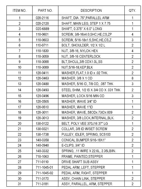
34 Part Assemblies - Frame Assembly Parts list 32
35 Part Assemblies - Frame Assembly See page 35 for parts list 33
36 Part Assemblies - Frame Assembly See page 35 for parts list 34
37 35
38 Maintenance Log Model Serial Number Mfg Date Date Cleaning Problem/Adjustment Part Replaced Service performed by Comments: 36
39

40
Pro Bike 6000 Series
 Pro Bike 6000 Series Preliminary Service Manual June 28, 2004 Pro Bike (6000 Series) Service Manual Table of Contents 1. Preventative Maintenance 2. Display Settings 3. Diagnostic Lights 4. Parts & Diagrams
Pro CrossTrainer Elite CrossTrainer
 Pro CrossTrainer Elite CrossTrainer Service Manual Table of Contents Table of Contents... 1 Preventive Maintenance... 2 Settings - Maintenance Mode... 3 Diagnostics - Display Codes... 5 Diagnostics - LED
2013 Elite T4000 (TM461C) Service Manual
 Service Manual") 2013 Elite T4000 (TM461C) Service Manual 1 TABLE OF CONTENTS CHAPTER 1: SERIAL NUMBER LOCATION...3 CHAPTER 2: PREVENTATIVE MAINTENANCE 2.1 Preventative Maintenance. 4 2.2 Tension and Centering the Running
2013 Elite T4000 (TM461C) Service Manual 1 TABLE OF CONTENTS CHAPTER 1: SERIAL NUMBER LOCATION...3 CHAPTER 2: PREVENTATIVE MAINTENANCE 2.1 Preventative Maintenance. 4 2.2 Tension and Centering the Running
Troubleshooting No UB Movement / Actuator Movement
 Troubleshooting UB Movement / Actuator Movement SOLUTIONS: A1 Recalibrate UB Arms te: If problem still exist refer to A7 solution A2 Replace Replace Actuator Start Stride on unit to power up display Press
LS8.0T Service Manual
 LS8.0T Service Manual 1 TABLE OF CONTENTS CHAPTER 1: SERIAL NUMBER LOCATION...3 CHAPTER 2: PREVENTATIVE MAINTENANCE 2.1 Preventative Maintenance. 4 2.2 Tension and Centering the Running Belt....6 CHAPTER
C554i Elliptical Fitness Crosstrainer
 C554i Elliptical Fitness Crosstrainer Warning: This service manual is for use by Precor trained service providers only. If you are not a Precor Trained Servicer, you must not attempt to service any Precor
RBK 815 Recumbent Cycle. RBK 815 Bicycle
 RBK 815 Bicycle Warning: This service manual is for use by Precor trained service providers only. If you are not a Precor Trained Servicer, you must not attempt to service any Precor Product; Call your
Cybex Arc Trainer Owner s & Service Manual. 7 - Service
 7 - Service Table of Contents......... iii Warnings/Cautions All warnings and cautions listed in this chapter are as follows:! WARNING: All maintenance activities shall be performed by qualified personnel.
Preventative Maintenance and Diagnostics
 Preventative Maintenance and Diagnostics JUNE 2016 Please Read Before You Begin IMPORTANT Before working on any Octane Fitness product, please take the time to look through the product specific manuals.
T & T Service Manual
 T101-04 & T202-03 Service Manual 1 2 3 Contents CHAPTER 1: SERIAL NUMBER LOCATION... 6 CHAPTER 2: PREVENTATIVE MAINTENANCE 2.1 Preventative Maintenance... 8 2.2 Tension and Centering the Running Belt...
E3x-01 elliptical Trainer
 E3x-01 elliptical Trainer SERVICE MANUAl chapter 1: Serial Number Location CHAPTER 1: Serial number location... 1 CHAPTER 2: Important Safety instructions 2.1 Read and Save These Instructions... 2 2.2
E5x-02 elliptical Trainer
 E5x-02 elliptical Trainer SERVICE MANUAl table of contents CHAPTER 1: Serial number location... 1 CHAPTER 2: Important Safety instructions 2.1 Read and Save These Instructions... 3 2.2 Electrical Requirements...
Pro4500 Service Manual Table of Contents
 Pro4500 Pro4500 Service Manual Table of Contents SECTION I: General Service Tips 1.1 Part Locations... 3 1.2 Diagnostic Mode Settings and Error Codes... 4 1.3 Suggested Dealer Stock List... 7 SECTION II:
LS10.0T Service Manual
 LS10.0T Service Manual 1 TABLE OF CONTENTS CHAPTER 1: SERIAL NUMBER LOCATION...3 CHAPTER 2: PREVENTATIVE MAINTENANCE 2.1 Preventative Maintenance. 4 2.2 Tension and Centering the Running Belt....6 CHAPTER
CALIFORNIA TRIMMER MOWER MAINTENANCE MANUAL
 CALIFORNIA TRIMMER MOWER MAINTENANCE MANUAL 2 Table of Contents Section 1: General Information Page Handle Assembly Instructions 4 Maintenance All Models 6 Oil Change Procedures All Models 9 Height Adjustment
Introduction. Contents. How to Use the Manual 1.2 Precautions 1.3 Product Support Assistance 1.4 Tools and Materials 1.5 Elliptical Edge Overview 1.
 Section 1.m-m..SYUNISEN"NC._ lwlc Introduction Welcome to the world of STAR TRAC. In your hands is the STAR TRAC Elliptical Edge Service Manual. This manual is designed to be easy to use, providing detailed
PREVENTIVE MAINTENANCE
 PREVENTIVE MAINTENANCE Overview Preventive maintenance (PM) is a schedule of planned maintenance actions aimed at the prevention of failures. PM is the best way to preserve and enhance equipment reliability
E7xE-01 elliptical Trainer
 E7xE-01 elliptical Trainer SERVICE MANUAl Table of contents CHAPTER 1: Serial number location... 1 CHAPTER 2: Important Safety instructions 2.1 Read and Save These Instructions... 3 2.2 Electrical Requirements...
R 3 x B i k e S e R V i C e M A N U A l
 R3x-01 Bike SERVICE MANUAl table of contents CHAPTER 1: Serial number location... 1 CHAPTER 2: Important Safety instructions 2.1 Read and Save These Instructions... 2 2.2 Electrical Requirements... 2
C 5 X C L I M B M I L L S E R V I C E M A N U A L
 C 5 X - 0 1 C L I M B M I L L S E R V I C E M A N U A L TABLE OF CONTENTS CHAPTER 1: SERIAL NUMBER LOCATION... 1 CHAPTER 2: IMPORTANT SAFETY INSTRUCTIONS 2.1 Read and Save These Instructions... 3 2.2 Electrical
R 3 X B I K E S E R V I C E M A N U A L
 R 3 X - 0 2 B I K E S E R V I C E M A N U A L TABLE OF CONTENTS CHAPTER 1: SERIAL NUMBER LOCATION... 1 CHAPTER 2: IMPORTANT SAFETY INSTRUCTIONS 2.1 Read and Save These Instructions... 2 2.2 Electrical
S-Drive Performance Trainer
 S-Drive Performance Trainer SERVICE MANUAl Table of contents CHAPTER 1: Serial number location... 1 CHAPTER 2: Important Safety instructions 2.1 Read and Save These Instructions... 2 2.2 Before Getting
IT ALL STARTS WITH A VISION IT ALL STARTS WITH A VISION FITNESS U 6 0 B I K E S E R V I C E M A N U A L
 IT ALL STARTS WITH A VISION IT ALL STARTS WITH A VISION FITNESS U 6 0 B I K E S E R V I C E M A N U A L TABLE OF CONTENTS CHAPTER 1: SERIAL NUMBER LOCATION... 1 CHAPTER 2: IMPORTANT SAFETY INSTRUCTIONS
C556, C556i Navy Elliptical Fitness Crosstrainer
 C556, C556i Navy Elliptical Fitness Crosstrainer Warning: This service manual is for use by Precor trained service providers only. If you are not a Precor Trained Servicer, you must not attempt to service
ONE YEAR LIMITED WARRANTY
 TABLE OF CONTENTS ONE YEAR LIMITED WARRANTY Warranty 1 Overview Drawing 3 Parts List 4 Hardware List 7 Assembly Instructions 9 How to Fold-Up the Extrusion 14 How to Fold-Down the Extrusion 15 Adjustment
SX1000 Service Manual SALES: CUSTOMER SERVICE:
 SX1000 Service Manual SALES: 800-278-3933 CUSTOMER SERVICE: 800-745-1373 Revision: August 1999 Table of Contents Section Page I. Overview 2 II. Troubleshooting Tables 3 III. Maintenance Procedures Procedure
TC1000 Service Manual SALES: CUSTOMER SERVICE:
 TC1000 Service Manual SALES: 800-278-3933 CUSTOMER SERVICE: 800-745-1373 Table of Contents Section Page I. Overview 2 II. Troubleshooting Tables 3 III. Maintenance Procedures Procedure 1 Removal and Reinstallation
Magnetic Elliptical Trainer
 Magnetic Elliptical Trainer ITEM NO.: 400 OWNER S MANUAL IMPORTANT: Read all instructions carefully before using this product. Retain this owner s manual for future reference. The specifications of this
WALKING TREADMILL SF-T1407M USER MANUAL
 WALKING TREADMILL SF-T1407M USER MANUAL IMPORTANT! Please retain owner s manual for maintenance and adjustment instructions. Your satisfaction is very important to us, PLEASE DO NOT RETURN UNTIL YOU HAVE
Customer Name: Serial Number: Y-Axis Stall
 Technician Name: Date: Technician Name: Date: Customer Name: Serial Number: Y-Axis Stall Issue Explanation and Background Each drive motor on the machine (the x, y and z axes motors) has a sensor called
Service Manual ISO7000R Recumbent Bike
 Service Manual ISO7000R Recumbent Bike Before Using this product, read this manual and follow all safety rules and operating instructions. Maintenance The ISO7000R is virtually maintenance free. After
C542i Elliptical Fitness Crosstrainer
 C542i Elliptical Fitness Crosstrainer Warning: This service manual is for use by Precor trained service providers only. If you are not a Precor Trained Servicer, you must not attempt to service any Precor
C524, C524i Elliptical Fitness Crosstrainer
 C524, C524i Elliptical Fitness Crosstrainer Warning: This service manual is for use by Precor trained service providers only. If you are not a Precor Trained Servicer, you must not attempt to service any
2.1 Read and Save These Instructions Electrical Requirements... 4
 E5x-03 Suspension elliptical SERVICE MANUAl E5X-04 SUSPENSION ELLIPTICAL SERVICE MANUAl Table of contents CHAPTER 1: Serial number location... 1 CHAPTER 2: Important Safety instructions 2.1 Read and Save
ESSENTIAL TIPS. Official Guide MAINTENANCE GUIDE XM-PRO II & XM-PRO III XM-PRO II & III. LIVE LONGER! LOOK AFTER YOUR TREADMILL & SAVE s
 TREADMILL MAINTENANCE GUIDE ESSENTIAL TIPS XM-PRO II & XM-PRO III Official Guide TREADMILL COMPONENTS? UNDERSTAND YOUR TREADMILL XM-PRO II & III MAINTENANCE SCHEDULE LIVE LONGER! LOOK AFTER YOUR TREADMILL
Service Manual. Model L500 and L600 Smart Lift. WARNING: Cancer and Reproductive Harm - Form #1-144 Rev.
 Service Manual Model L500 and L600 Smart Lift WARNING: Cancer and Reproductive Harm - www.p65warnings.ca.gov. Form #1-144 Rev. 2/5/19 Table of Contents Parts Breakdown 3 Monthly Maintenance Checklist 5
Service Manual Model L1000 Smart Lift
 Service Manual Model L1000 Smart Lift Form #1-147 Rev. 10/1/13 Table of Contents Parts Breakdown 3 Monthly Maintenance Checklist 5 Smart Lift Operating Instructions 7 Scale Calibration 8 Advanced Smart
PRO INDOOR CYCLING BIKE
 PRO INDOOR CYCLING BIKE SF-B901 USER MANUAL IMPORTANT! Please retain owner s manual for maintenance and adjustment instructions. Your satisfaction is very important to us, PLEASE DO NOT RETURN UNTIL YOU
TL4076 Top 5 Tips Get to know your TL4076
 TL4076 Top 5 Tips Get to know your TL4076 Thermal Break with Teflon liner (behind fan) Hot End Assembly Fan Heat Block Extruder with toothed gear(brass) and idler (steel) Filament Guide Tube Nozzle Cable
Maintenance and Repair
 Maintenance and Repair WARNING ALWAYS shut off the engine, remove key from ignition, make sure the engine is cool, and disconnect the spark plug and positive battery terminal from the battery before cleaning,
RECUMBENT BIKE IMPORTANT: Read all instructions carefully before using this product. Retain this
 RECUMBENT BIKE IMPORTANT: Read all instructions carefully before using this product. Retain this owner s manual for future reference. The specifications of this product may vary from this photo, subject
A5x-02 Ascent Trainer
 A5x-02 Ascent Trainer SERVICE MANUAl table of contents CHAPTER 1: Serial number location... 1 CHAPTER 2: Important Safety instructions 2.1 Moving the Unit... 3 2.2 Read and Save These Instructions...
BELT DRIVE PRO INDOOR CYCLING BIKE SF-B901B USER MANUAL
 BELT DRIVE PRO INDOOR CYCLING BIKE SF-B901B USER MANUAL IMPORTANT! Please retain owner s manual for maintenance and adjustment instructions. Your satisfaction is very important to us, PLEASE DO NOT RETURN
MAGNETIC RECUMBENT BIKE
 MAGNETIC RECUMBENT BIKE SF-RB4417 USER MANUAL IMPORTANT: Please read this manual carefully before using the product. Retain owner s manual for future reference. For Customer Service, please contact: support@sunnyhealthfitness.com
R o w e R ( A R 1 1 ) S e R V I C e M A N U A l
 S e R V I C e M A N U A l") Rower-02 (AR11) SERVICE MANUAl Table of contents CHAPTER 1: Serial number location... 1 CHAPTER 2: Important Safety instructions 2.1 Read and Save These Instructions... 2 2.2 Locating the Unit... 2 2.3
Rower-02 (AR11) SERVICE MANUAl Table of contents CHAPTER 1: Serial number location... 1 CHAPTER 2: Important Safety instructions 2.1 Read and Save These Instructions... 2 2.2 Locating the Unit... 2 2.3
U 3 X B I K E S E R V I C E M A N U A L
 U 3 X - 0 2 B I K E S E R V I C E M A N U A L TABLE OF CONTENTS CHAPTER 1: SERIAL NUMBER LOCATION... 1 CHAPTER 2: IMPORTANT SAFETY INSTRUCTIONS 2.1 Read and Save These Instructions... 3 2.2 Electrical
Procedure Replacing a Cover
 Procedure 7.1 - Replacing a Cover Cover Removal 1. Remove two screws, one each side, from the front of the top cover. Remove the top cover. See Diagram 7.1. Diagram 7.1 - RBK 815 Covers Top Cover Left
Dealer4 Maintenance, Adjusting and Cleaning Manual ver: 1.0
 Dealer4 Maintenance, Adjusting and Cleaning Manual ver: 1.0 Version information: Ver 1.0: First issue : 14/04/2008 - use word Board instead of Card Box - combine with Delaer4 Adjusting Manual 1V0 1 1 Dealer4
ACCORD ELLIPTICAL TRAINER ITEM NO: 93470
 ACCORD ELLIPTICAL TRAINER ITEM NO: 93470 OWNER S MANUAL IMPORTANT: Read all instructions carefully before using this product. Retain this owner s manual for future reference. The specifications of this
C960, C962, C964 Treadmill
 C960, C962, C964 Treadmill Warning: This service manual is for use by Precor trained service providers only. If you are not a Precor Trained Servicer, you must not attempt to service any Precor Product;
SUNNY PRO INDOOR CYCLING BIKE
 SUNNY PRO INDOOR CYCLING BIKE SF-B901 USER MANUAL IMPORTANT! Please retain owner s manual for maintenance and adjustment instructions. Your satisfaction is very important to us, PLEASE DO NOT RETURN UNTIL
ASSEMBLY INSTRUCTIONS / OWNERS MANUAL AIR BIKE AB-1
 AIR BIKE AB- ASSEMBLY INSTRUCTIONS / OWNERS MANUAL IMPORTANT : READ ALL ASSEMBLY INSTRUCTIONS AND SAFETY PRECAUTIONS BEFORE USING THIS PRODUCT. REFERENCE ALL SAFETY GUIDELINES AND WARNING LABELS. RETAIN
CARE AND MAINTENANCE INSTRUCTIONS
 STRONG. SMART. BEAUTIFUL. CARE AND MAINTENANCE INSTRUCTIONS In order to maximize life span, and minimize down time, all MATRIX equipment requires regular cleaning, and maintenance items performed on a
CLUB SERIES HIP AB/ADDUCTOR
 CLUB SERIES HIP AB/ADDUCTOR ASSEMBLY INSTRUCTIONS Part # 718601 Rev E 1 Revision: 1/2/03 KEY PART # DESCRIPTION QTY KEY PART # DESCRIPTION QT Y 1 71710xx TOWER 1 22 3102915 3/8 X 3-1/ BOLT 2 1A 6692601
RECUMBENT BIKE WITH ARM EXERCISER
 RECUMBENT BIKE WITH ARM EXERCISER SF-RB4631 USER MANUAL IMPORTANT! Please retain owner s manual for maintenance and adjustment instructions. Your satisfaction is very important to us, PLEASE DO NOT RETURN
FlexJet Carriage Circuit Board (PCB) Replacement
 Replacement") P/N: 111484 R0 14140 NE 200th St. Woodinville, WA. 98072 PH: (425) 398-8282 FX: (425) 398-8383 ioline.com FlexJet Carriage Circuit Board (PCB) Replacement Notices: Warning! Ensure that all AC power cables
P/N: 111484 R0 14140 NE 200th St. Woodinville, WA. 98072 PH: (425) 398-8282 FX: (425) 398-8383 ioline.com FlexJet Carriage Circuit Board (PCB) Replacement Notices: Warning! Ensure that all AC power cables
1 Green Pressure Regulator Spring Automatic transmissions operate at temperatures between 150ºF and
 Installation Instructions for 603107 Valve Body Kit C-4 1970 & Later Tools Required Speed Handle or Ratchet 3/8 Drive 1/2 Socket 3/8 Drive 7/16 Socket 3/8 Drive 5/16 Socket 3/8 Drive Small Screwdriver
Crestline Dampening System. Installation Instructions. Hamada RS34 & VS34 Satellite Unit. For Presses Originally Equipped With. Integrated Dampeners
 Crestline Dampening System Installation Instructions Hamada RS34 & VS34 Satellite Unit For Presses Originally Equipped With Integrated Dampeners X88-113 01/2001 Rev-A GENERAL INFORMATION ATTENTION CRESTLINE
Marsh Shipping Supply Co. LLC. Marsh TD2100 Electric Taper Technical Manual
 Marsh Shipping Supply Co. LLC Marsh TD2100 Electric Taper Technical Manual 2 A wall-socket must be close to the product and readily accessible. The overall system is protected against overload by the branch
To increase the height of the trailer increase the length, to reduce the height, decrease the length of the link.
 RIDE HEIGHT (CONTINUED) 8.8.2. Trailer Suspension The trailer suspension is set at the factory and should always return to this setting when the height control valve is returned to the central position,
Subject Underhood G System Error Codes and Symptoms System or Parts affected
 System or Parts affected Index Underhood70G (V90Gxxx) System or Parts affected... 1 Overview... 1 Identifying your System... 1 Retrieving Logged Error Messages... 1 Error Messages... 3 Error Message Table...
C842i, C846i Bicycle
 C842i, C846i Bicycle Warning: This service manual is for use by Precor trained service providers only. If you are not a Precor Trained Servicer, you must not attempt to service any Precor Product; Call
GT-200 GATE VALVES PN16, Screwed end
 Document No. : MD-QO-04-281 Date : 2009/07 /17 Version : 1.0 GT-200 GATE VALVES PN16, Screwed end USER MANUAL Modentic Industrial Corporation 14F-1,No.57Taya Rd.,Taichung,Taiwan,R.O.C. Email:modentic@ms9.hinet.net
Service Manual Model S800 Smart Stand
 Service Manual Model S800 Smart Stand Form #1-146 Rev. 10/3/13 Table of Contents Parts Breakdown 3 Monthly Maintenance Checklist 7 Smart Stand Operating Instructions 9 Scale Calibration 10 Advanced Smart
Not for Reproduction. BILLY GOAT AERATOR Owner's Manual AE401, AE401H, AE401H5T Replacement Parts. AE Owner s Manual TINE ROW KIT TINE KIT P/N
 BILLY GOAT AERATOR Owner's Manual AE401, AE401H, AE401H5T Replacement Parts TINE ROW KIT Complete tine row set for replacement of one complete row of tines. Includes mounting plates, spacer, and all hardware.
M661 Instruction Manual
 M661 Instruction Manual Please inspect your machine carefully upon receipt. Let us know immediately if you note any damage. -IMPORTANT NOTICE- THIS MACHINE IS NOT TO BE OPERATED BY ANYONE UNTIL HAVING
MX-T3x(TM94E) AC SYSTEM SERVICE MANUAL
 AC SYSTEM SERVICE MANUAL") MX-T3x(TM94E) AC SYSTEM SERVICE MANUAL 1 TABLE OF CONTENTS SECTION 1:SERIAL NUMBER LOCATION SECTION 2:MOVING THE UNIT SECTION 3:IMPORTANT SAFETY INSTRUCTIONS SECTION 4:PREVENTATIVE MAINTENANCE 4.1 Maintenance
MX-T3x(TM94E) AC SYSTEM SERVICE MANUAL 1 TABLE OF CONTENTS SECTION 1:SERIAL NUMBER LOCATION SECTION 2:MOVING THE UNIT SECTION 3:IMPORTANT SAFETY INSTRUCTIONS SECTION 4:PREVENTATIVE MAINTENANCE 4.1 Maintenance
BELT DRIVE INDOOR CYCLING BIKE
 BELT DRIVE INDOOR CYCLING BIKE SF-B1002 USER MANUAL IMPORTANT: Read all instructions carefully before using this product. Retain owner s manual for future reference. For customer service, please contact:
Table of Contents. Assembly Instructions 1. Assembly Figure. 4
 Table of Contents Assembly Instructions 1 Assembly Figure. 4 Maintenance Instructions.. 5 Daily. 5 Weekly.. 5 Lubricating the Chain... 5 Check Friction Belt... 6 Clean Bike.6 Monthly.... 6 Chain Guard
Service Manual Model S400 and S500 Smart Stand
 Service Manual Model S400 and S500 Smart Stand Form #1-145 Rev. 10/3/13 Table of Contents Parts Breakdown 3 Monthly Maintenance Checklist 7 Smart Stand Operating Instructions 9 Scale Calibration 10 Advanced
C546i Self Powered Elliptical Fitness Crosstrainer (version 2, serial codes AA32, AAAJ, ADEE)
") C546i Self Powered Elliptical Fitness Crosstrainer (version 2, serial codes AA32, AAAJ, ADEE) Warning: This service manual is for use by Precor trained service providers only. If you are not a Precor Trained
C546i Self Powered Elliptical Fitness Crosstrainer (version 2, serial codes AA32, AAAJ, ADEE) Warning: This service manual is for use by Precor trained service providers only. If you are not a Precor Trained
NOTE: DISCONNECT MAIN POWER LOCK OUT AND TAG BEFORE PERFORMING ANY PROCEDURES IN THIS SECTION.
 M E C H A N I C A L S E T U P & A D J U S T M E N T S NOTE: DISCONNECT MAIN POWER LOCK OUT AND TAG BEFORE PERFORMING ANY PROCEDURES IN THIS SECTION. NOTE: All adjustments should be made with the sealer
CROSS TRAINING MAGNETIC RECUMBENT BIKE
 CROSS TRAINING MAGNETIC RECUMBENT BIKE SF-RB4708 USER MANUAL IMPORTANT! Please retain owner s manual for maintenance and adjustment instructions. Your satisfaction is very important to us, PLEASE DO NOT
CRESTLINE DAMPENING SYSTEM INSTALLATION INSTRUCTIONS. Ryobi 3302M Itek 3985 A.B. Dick 9985 X /99
 CRESTLINE DAMPENING SYSTEM INSTALLATION INSTRUCTIONS Ryobi 3302M Itek 3985 A.B. Dick 9985 X88-32 3/99 GENERAL INFORMATION ATTENTION CRESTLINE DAMPENER OWNER Accel Graphic Systems provides parts and service
INSTALLATION GUIDE. Doc ID: A Doc Rev:
 REKLUSE MOTOR SPORTS EXP Kit for Harley-Davidson Big Twin Hydraulic-Actuated OVERVIEW INSTALLATION GUIDE Doc ID: 191-6200A Doc Rev: 061215 This kit replaces the OEM clutch pack (friction disks and drive
Lifecycle 9500HR/9100 Series Recumbent Exercise Bikes Customer Support Services SERVICE MANUAL
 Lifecycle 9500HR/9100 Series Recumbent Exercise Bikes Customer Support Services SERVICE MANUAL INTRODUCTION HOW TO USE SERVICE MANUAL AND CONTACT CUSTOMER SUPPORT SERVICES This service manual is applicable
8G Brake Assembly Alignment
 8G Brake Assembly Alignment 8G (9-5250) This document explains how to do the 8G (9-5250) brake assembly alignment in order to eliminate noise in the drive system coming from the mis-aligned brake plates.
Owners Manual 1 E720
 Owners Manual 1 E720 Training with E720 2 Contents 1. Contents of E720 Box. 2. E720 assembly instructions. 3. Tank filling and water treatment. 4. Long term water treatment and basic operation. As with
RolsplicerTM. Maintenance Manual And Illustrated Parts List
 RolsplicerTM Maintenance Manual And Illustrated Parts List List of Illustrations Figure Page. Rolsplicer 3 2. Roller Adjustment 4 3. Rolsplicer 6 4. Lid Hold Down Assembly 8 5. Automatic Lid Speed Adjustment
GENERAL INFO TROUBLE SHOOTING. Version 1.1
 GENERAL INFO TROUBLE SHOOTING Version 1.1 GENERAL INFO Before beginning any exercise, please consult your physician Wipe off the cycle after EVERY use. If necessary, use water in a spray bottle and a tissue
XINGGUI Elliptical Cross Trainer
 XINGGUI Elliptical Cross Trainer ITEM NO.: 93040 OWNER S MANUAL IMPORTANT: Read all instructions carefully before using this product. Retain this owner s manual for future reference. The specifications
TROUBLESHOOTING TROUBLESHOOTING
 FOR 2007 TREADMILLS: (T9200 SIMPLE, T9500 SIMPLE, T9600 SIMPLE, T9250 SIMPLE, T9450 SIMPLE) (T9200 DELUXE, T9500 DELUXE, T9600 DELUXE, T9250 DELUXE, T9450 DELUXE) (T9200 PREMIER, T9500 PREMIER, T9600 PREMIER,
Section 5: Parts Replacement
 Section 5: Parts Replacement Should the STAR TRAC 4500 Treadmill experience a problem requiring replacement of a specific part, the following procedures will help and instruct in the replacement of major
Thermo-Bob 3 Installation Manual: KLR650E (2008 and newer)
") Thermo-Bob 3 Installation Manual: KLR650E (2008 and newer) Thank you for purchasing the Thermo-Bob 3 radiator bypass system for the KLR650. Since the KLR already has a doohickey, it seemed that this thingamabob
Thermo-Bob 3 Installation Manual: KLR650E (2008 and newer) Thank you for purchasing the Thermo-Bob 3 radiator bypass system for the KLR650. Since the KLR already has a doohickey, it seemed that this thingamabob
PLEASE BE SAFE WHEN RIDING ALWAYS WEAR A HELMET AND OBEY ALL LAWS!
 X-Treme TM Electric Scooters X-10 Electric Scooter Owner s Manual PLEASE BE SAFE WHEN RIDING ALWAYS WEAR A HELMET AND OBEY ALL LAWS! Page1 IMPORTANT BATTERY MAINTENANCE and CHARGING INSTRUCTIONS 1. You
SPACE SAVING FOLDING TREADMILL SF-T7632 USER MANUAL
 SPACE SAVING FOLDING TREADMILL SF-T7632 USER MANUAL IMPORTANT: Read all instructions carefully before using this product. Retain owner s manual for future reference. For customer service, please contact:
SOP Instructions & Check Sheet for MATRIX X Bike Installation
 1000390 Rev 2 SOP Instructions & Check Sheet for MATRIX X Bike Installation Tools Needed 1. 13mm, 15mm (for pedals) and 17mm wrenches 2. Metric Hex Keys (long) set including 3mm, 4mm, 5mm, and 6mm. 3.
Thermo-Bob Installation Manual: KLR650A ( )
") Thermo-Bob Installation Manual: KLR650A (1987-2007) Thank you for purchasing the Thermo-Bob radiator bypass system for the KLR650. Since the KLR already has a doohickey, it seemed that this thingamabob
Thermo-Bob Installation Manual: KLR650A (1987-2007) Thank you for purchasing the Thermo-Bob radiator bypass system for the KLR650. Since the KLR already has a doohickey, it seemed that this thingamabob
M52tu-M54 VANOS Assembly & Timing Using G.A.S. Professional Cam Tool Kit
 Home BMW Solutions Porsche Solutions DIY Tech Engine Services Dyno Services Machining About Contact Store Tool Rental M52tu-M54 VANOS Assembly & Timing Using G.A.S. Professional Cam Tool Kit This procedure
Super T QR20 INSTRUCTIONS GENERAL RULES
 INSTRUCTIONS GENERAL RULES 1. Where specified, assemble and disassemble the shock absorption system using the MARZOCCHI special tools only. 2. On reassembling the suspension system, always use new seals.
INSTALLATION & USER S GUIDE
 REKLUSE MOTOR SPORTS The Rekluse Core EXP Kit with Adjustable Slave Cylinder INSTALLATION & USER S GUIDE Doc ID: 191-7704A Doc Rev: 102915 OVERVIEW This kit replaces the OEM core clutch components including
FlexJet - Flex Cable Replacement
 P/N: 109515R0 14140 NE 200th St. Woodinville, WA. 98072 PH: (425) 398-8282 FX: (425) 398-8383 FlexJet - Flex Cable Replacement Notices: Warning! Ensure that all AC power cables are removed from the printer
PRODUCT INFORMATION BULLETIN #3365 DIGITAL MOTOR CONTROL PLATTER SYSTEMS For Serial Number and After
 PRODUCT INFORMATION BULLETIN #3365 DIGITAL MOTOR CONTROL PLATTER SYSTEMS For Serial Number 28640996 and After Record Platter System Identification Numbers Here: Model # Serial # Table of Contents Program
SCIFIT Service Manual 4000 Series Stepper
 SCIFIT Service Manual 4000 Series Stepper SCIFIT Service Center 5616 A, S. 122 E. AVE. TULSA, OK 74146 800-745-1373 ext 21 scifit@busprod.com TABLE OF CONTENTS Replacement Parts List For Stepper... 3 Replacement
ISO1000R Service Manual SALES: CUSTOMER SERVICE:
 ISO1000R Service Manual SALES: 800-278-3933 CUSTOMER SERVICE: 800-745-1373 Revision: August 1999 Table of Contents Section Page I. Overview 2 II. Troubleshooting Tables 3 III. Maintenance Procedures Procedure
WARNING: ALWAYS UNPLUG THE TREADMILL FROM THE ELECTRICAL OUTLET BEFORE SERVICING THE UNIT.
 Z700-A82 / 120V Treadmill WARNING: ALWAYS UNPLUG THE TREADMILL FROM THE ELECTRICAL OUTLET BEFORE SERVICING THE UNIT. Table of Contents TABLE OF CONTENTS Table of Contents...1 Table of Figures...3 Description...4
Owners Manual E820/E920
 Owners Manual E820/E920 Wheelchair Accessible Training with E820/E920 2 Contents 1. Contents of E820/920 Box. 2. E820/E920 assembly instructions. 3. E820/E920 Control arm. 4. E920 Adjustable crank arms.
Oreck Magnesium Series Service Manual. The Oreck Manufacturing Company
 Oreck Magnesium Series Service Manual The Oreck Manufacturing Company 08/2012 10/2011 The Oreck Manufacturing Company Contents Covering all Magnesium Upright Models Including: LW100, LW125, LW1000, AND
Auto Sentry-eXP Maintenance. Revised 12/21/07
 Auto Sentry-eXP Maintenance Revised 12/21/07 Maintenance Procedures for Auto Sentry exp Bill Dispenser Credit Card Reader Bill Acceptor Bill Dispenser Maintenance Bill Dispenser Problem / Cause Bill Dispenser
EASY ADJUSTABLE SEAT RECUMBENT BIKE
 EASY ADJUSTABLE SEAT RECUMBENT BIKE SF-RB4616 USER MANUAL IMPORTANT! Please retain owner s manual for maintenance and adjustment instructions. Your satisfaction is very important to us, PLEASE DO NOT RETURN