R 3 x B i k e S e R V i C e M A N U A l
|
|
|
- Gerald Gilbert
- 5 years ago
- Views:
Transcription
1 R3x-01 Bike SERVICE MANUAl
2
3 table of contents CHAPTER 1: Serial number location... 1 CHAPTER 2: Important Safety instructions 2.1 Read and Save These Instructions Electrical Requirements... 2 CHAPTER 3: Preventative Maintenance 3.1 Recommended Cleaning Tips Check for Damaged Parts Care and Maintenance Instructions... 4 CHAPTER 4: CONSOLE OVERLAY AND WORKOUT DESCRIPTION 4.1 Console Description Workout Setup Steps - Manual Workout Setup Steps - Fat Burn Workout Setup Steps - Level Based Workout Setup Steps - Fitness Test Workout Setup Steps - Target Heart Rate Workout Setup Steps - Constant Watts... 8 CHAPTER 5: Manager MODE 5.1 Using Manager Mode Manager Mode Overview CHAPTER 6: ENGINEERING / SERVICE MODE 6.1 Engineering / Service Mode Overview CHAPTER 7: Troubleshooting 7.1 Electrical Diagrams Troubleshooting - Keypad Issues Troubleshooting - Resistance Issues Troubleshooting - Pedal Slipping Troubleshooting - Noise Issues Troubleshooting - Console Issues Troubleshooting - NO RPM Reading Troubleshooting - Heart Rate Issues Troubleshooting - Seat Issues CHAPTER 8: PART REPLACEMENT GUIDE 8.1 Console Replacement Handlebar Replacement Cup Holder Replacement Console Keypad / Overlay Replacement Console Mast Replacement Seat Pad Replacement Back Pad Replacement i
4 table of contents 8.8 HR Handlebar Replacement HR Grips Replacement Upper Seat Frame Replacement Lower Seat Frame Replacement Seat Adjustment Handle Replacement Rear Shrouds Removal Pedal Replacement Front Shroud Removal Lower Control Board Replacement Drive Belt Replacement Generator Belt Replacement Generator Replacement Pulley Axle Set Replacement Crank Axle Set Replacement Testing the Bike CHAPTER 9: Bike specifications and assembly guide 9.1 R3x-01 Bike Specifications Fasteners and Assembly Tools Assembly Instructions Adjusting the Pedal Straps and Seat Leveling the Bike TV Bracket Installation ii iv
5 Chapter 1: Serial number location 1.1 Serial Number Location A serial number plate is located below the bottom of the console mast beneath a rubber boot. There is also a serial number tag on the middle of the main frame pointed towards the floor. 1
6 Chapter 2: Important Safety Instructions 2.1 Read and Save these instructions To ensure your safety and protect the equipment, read all instructions before operating the MATRIX R3x-01 Bike. Remind the users that before undertaking any fitness program, they should obtain complete physical examinations from their physicians. If, at any time while exercising, the user experiences dizziness, pain, or shortness of breath, nausea or feels faint, he or she must stop immediately. CAUTION! If you experience chest pains, nausea, dizziness, or shortness of breath, stop exercising immediately and consult your physician before continuing. CAUTION! Any changes or modifications to this equipment could void the product warranty. * This bike is only to be used for its intended purpose described in this manual. Do not use attachments that have not been recommended by Matrix. * Never drop or insert objects into any opening. Keep hands away from moving parts. If the item cannot be reached, contact a Matrix authorized dealer for assistance. * Never operate the unit if it is damaged, not working properly, when it has been dropped, or has been dropped in water. * Keep hands and feet clear at all times from moving parts to avoid injury. * Do not use this product outdoors, near swimming pools or in areas of high humidity. * Do not operate where aerosol (spray) products are being used or when oxygen is being administered. 2.2 electrical requirements The Matrix R3x-01 Bike is designed to be self powered and does not require an external power supply source to operate. The battery in the console needs to be charged for 3-4 hours when first installed. Until the battery is fully charged, the 30 second pause feature may not function fully. The charging does not need to be continuous for 3-4 hours, but over combined workouts equaling 3-4 hours. * Do not use this product in bare feet. Do not wear shoes with heels, leather soles, cleats, or spikes while exercising. * Do not remove the side covers. Service should only be done by an authorized service technician. * Close supervision is necessary when used near children, invalids, or disabled people. * When the bike is in use, young children and pets should be kept at least 3 meters / 10 feet away. * Assemble and operate the bike on a solid, level surface. * Never face backward while using the Matrix R3x-01 Bike. * Use the stationary handlebars when mounting or dismounting the bike. * Do not wear clothing that might catch on any moving parts of this bike. 2
7 Chapter 3: PREVENTATIVE MAINTENANCE 3.1 recommended cleaning tips Preventative maintenance and daily cleaning will prolong the life and look of your MATRIX R3x-01 Bike Please read and follow these tips. * Position the equipment away from direct sunlight. The intense UV light can cause discoloration on plastics. * Locate your equipment in an area with cool temperatures and low humidity. * Clean with a soft 100% cotton cloth. * Clean with soap and water or other non-ammonia based all purpose cleaners. * Wipe seats, pedals, console, heart rate grips, and the handlebar clean after each use. 3.2 Check for damaged parts DO NOT use any equipment that is damaged or has worn or broken parts. Use only replacement parts supplied by Matrix Fitness Systems. MAINTAIN LABELS AND NAMEPLATES. Do not remove labels for any reason. They contain important information. If unreadable or missing, contact Matrix Fitness Systems for a replacement at or MAINTAIN ALL EQUIPMENT. Preventative maintenance is the key to smoothly operating equipment. Equipment needs to be inspected at regular intervals. Defective components must be kept out of use until they are repaired. Ensure that any person(s) making adjustments or performing maintenance or repair of any kind is qualified to do so. Matrix Fitness Systems will provide service and maintenance training at our corporate facility upon request or in the field if proper arrangements are made. * Do not pour liquids directly onto your equipment. This can cause damage to the equipment and in some cases electrocution. * Check pedal straps weekly for wear. * Adjust leveling feet when equipment wobbles or rocks. * Maintain a clean area around the equipment, free from dust and dirt. 3
8 Chapter 3: PREVENTATIVE MAINTENANCE 3.3 Care and maintenance instructions In order to maximize life span, and minimize down time, all MATRIX equipment requires regular cleaning, and maintenance items performed on a scheduled basis. This section contains detailed instructions on how to perform these items and the frequency of which they should be done. Some basic tools and supplies will be necessary to perform these tasks which include (but may not be limited to): * Metric Allen wrenches * #2 Phillips head screwdriver * Adjustable wrench * Torque wrench (capability to read foot lbs and inch lbs) * Lint free cleaning cloths * Teflon based spray lubricant such as "Super Lube" or other Matrix approved products. * Mild water soluble detergent such as "Simple Green" or other Matrix approved products * Vacuum cleaner with an extendable hose and crevasse tool attachment. You may periodically see addendums to this document, as the Matrix Technical Support Team identifies items that require specific attention, the latest version will always be available on the Matrix web site at DAILY MAINTENANCE ITEMS 1) Look and listen for loose fasteners, unusual noises, and any other indications that the equipment may be in need of service. 2) Clean the bike before and after each use, including: a. Use a damp, soft cloth with water or mild liquid detergent to clean all exposed surfaces. DO NOT use ammonia, chlorine, or any acid based cleaners. b. Keep the console display free of fingerprints and salt build up caused by sweat. WEEKLY MAINTENANCE ITEMS 1) Frequently vacuum the floor beneath the unit to prevent the accumulation of dust and dirt which can affect the smooth operation of the unit. 2) Check the pedal straps for damage. 3) Clean the grooves on the foot pedals. MONTHLY MAINTENANCE ITEMS 1) Inspect the console, seat, pedals, and shrouds for damage. 2) Tighten the pedals onto their respective cranks using a 15 mm wrench. 3) Adjust the leveling feet if equipment rocks or wobbles. 4) Adjust and tighten the seat rollers as needed as outlined in Section 7.9. QuARTERLY MAINTENANCE ITEMS 1) Remove the front shrouds and check the belt for damage, alignment, and proper tension. 4

9 Chapter 4: Console Overlay and workout description 4.1 Console Description PROGRAM KEYS: Simple program selection buttons make Matrix bikes easy to use. The bike features eight programs. START / QUICK START: One touch Quick Start and Start any time during preference selection. UP / DOWN LEVEL: Easy information and level selection. SELECT / SELECT SCREEN / RESET: This multi-function button enters information when setting up programming options, toggles information displayed and if held down for 5 seconds, resets the bike to Start-up Mode. 5
10 chapter 4: console overlay and workout description 4.2 workout setup steps - manual 4.4 workout setup steps - level based QUICK START - Press to immediately begin a workout. Workout, resistance level, and time will automatically go to default settings. Pressing QUICK START will not prompt user for age, weight, or level settings. MANUAL - Manual allows the user to input more information while defining their own workout. Calorie expenditure will be more accurate when inputting information in Manual than by pressing QUICK START. 1) Start pedaling, press the MANUAL key. 2) Select Level by using the UP or DOWN LEVEL keys and press SELECT. 3) Select Time by using the UP or DOWN LEVEL keys and press SELECT. 4) Select Weight by using the UP or DOWN LEVEL keys and press SELECT. 5) The display will read Starting 3, Starting 2, Starting 1, and then the program will begin. 4.3 workout setup steps - fat burn FAT BURN - Fat burn is a level based program that is designed to help users burn fat through various resistance level changes. 1) Start pedaling and press the FAT BURN key. 2) Select Level by using the UP or DOWN LEVEL keys and press SELECT. 3) Select Time by using the UP or DOWN LEVEL keys and press SELECT. 4) Select Weight by using the UP or DOWN LEVEL keys and press SELECT. 5) The display will read Starting 3, Starting 2, Starting 1, and then the program will begin. ROLLING HILLS - The Rolling Hills program is a level based program that automatically adjusts the resistance level to simulate real terrain. 1) Start pedaling and press the ROLLING HILLS key. 2) Select Level by using the UP or DOWN LEVEL keys and press SELECT. 3) Select Time by using the UP or DOWN LEVEL keys and press SELECT. 4) Select Weight by using the UP or DOWN LEVEL keys and press SELECT. 5) The display will read Starting 3, Starting 2, Starting 1, and then the program will begin. INTERVAL TRAINING - The Interval Training program is a level based program that automatically adjusts the resistance of the machine from low to high intensity settings at regular intervals. 1) Start pedaling and press the INTERVAL TRAINING key. 2) Select Level by using the UP or DOWN LEVEL keys and press SELECT. 3) Select Time by using the UP or DOWN LEVEL keys and press SELECT. 4) Select Weight by using the UP or DOWN LEVEL keys and press SELECT. 5) The display will read Starting 3, Starting 2, Starting 1, and then the program will begin. RANDOM - Random is a level based workout that randomly adjusts the resistance of the machine. 1) Start pedaling and press the key next to RANDOM key. 2) Select Level by using the UP or DOWN LEVEL keys and press SELECT. 3) Select Time by using the UP or DOWN LEVEL keys and press SELECT. 4) Select Weight by using the UP or DOWN LEVEL keys and press SELECT. 5) The display will read Starting 3, Starting 2, Starting 1, and then the program will begin. 6
11 Chapter 4: Console overlay and workout description 4.5 WORKOUT SETUP STEPS - Fitness test FITNESS TEST -The Cooper Fitness Test measures cardiovascular fitness and proves an estimated sub-maximal VO2 result. It is based on power output according to ACSM standards and was developed by the Cooper Institute ( User RPMs must remain between RPM during the test. The test will end when the user can no longer maintain this speed. Use of a heart rate strap is optional but provides more data. The test starts at a low intensity level and gradually increases in intensity (difficulty) every 2 minutes. As it increases, the user must maintain RPM to advance to the next level. The test could take upwards of 30+ minutes for very fit individuals. Once the test ends a recovery period (cool down) will begin and the user's results are calculated and displayed. Results are based on the number of stages completed. 1) Start pedaling and press the FITNESS TEST key. 2) Select Age by using the UP or DOWN LEVEL keys and press SELECT. 3) Select Gender by using the UP or DOWN LEVEL keys and press SELECT. 4) Select Weight by using the UP or DOWN LEVEL keys and press SELECT. 5) The display will read Starting 3, Starting 2, Starting 1, and then the program will begin. 6) Once the workout is complete, the display will read the results of the Fitness Test. Percentile values for maximal Aerobic Power Age Percentile Men Women

12 Chapter 4: Console overlay and workout description 4.6 Workout Setup steps - TARGET heart rate TARGET HEART RATE - The Matrix R3x-01 Bike comes with standard digital contact heart rate sensors and are POLAR telemetry compatible. The heart rate control workout mode allows the user to program their desired heart rate zone, and the bike will automatically adjust the level based upon the user's heart rate. The heart rate zone is calculated using the following equation: (220-Age)8%=target heart rate zone. The user must wear a POLAR telemetric strap or continually hold onto the contact heart rate grips for this workout. Locate the metal sensors on the handlebars of the bike. Notice that there are two separate pieces of metal on each grip. You must be making contact with both pieces of each grip to get an accurate heart rate reading. You can grab these sensors in any program to view your current heart rate. 4.7 workout setup steps - CONSTANT watts CONSTANT WATTS - Constant Watts is a unique program that allows you to vary your cadence or RPM and the bike's resistance level will adjust accordingly to your selected goal. The quicker you pedal, the less resistance for the goal selected. 1) Start pedaling and press the CONSTANT WATTS key. 2) Select Watts by using the UP or DOWN LEVEL keys and press SELECT. 3) Select Time by using the UP or DOWN LEVEL keys and press SELECT. 4) Select Weight by using the UP or DOWN LEVEL keys and press SELECT. 5) The display will read Starting 3, Starting 2, Starting 1, and the program will begin. 1) Start pedaling and press the HEART RATE key. 2) Select Age by using the UP or DOWN LEVEL keys and press SELECT. 3) Select Target HR Percentage by using the UP or DOWN LEVEL keys and press SELECT. 4) Select Time by using the UP or DOWN LEVEL keys and press SELECT. 5) Select Weight by using the UP or DOWN LEVEL keys and press SELECT. 6) The display will read Starting 3, Starting 2, Starting 1, and the program will begin. 8
13 Chapter 5: MANAGER MODE 5.1 Using Manager Mode The Manager's Custom Mode allows the club owner to customize the bike for the club. 1) To enter Manager Mode, press and hold down the UP and DOWN LEVEL keys. Continue to hold down these two keys until the display reads Manager Mode and hit SELECT (Figure A). 2) To scroll through the list of options in Manager Mode, use the UP and DOWN LEVEL keys. Each of the custom settings will show on the display. 3) To select a custom setting, press the SELECT key when the desired setting is shown. 4) To change the value of the setting, use the UP and DOWN LEVEL keys. 5) To confirm and save the value of the setting, press the START key. 6) Press the START key 2 times to return to normal operation. 9
14 Chapter 5: MANAGER MODE 5.2 Manager mode overview CUSTOM SETTING DEFAULT MINIMUM MAXIMUM Description Maximum Time 95 min 10 min 95 min Sets the total run time of any program. Default Time 20 min 10 min Maximum Time Setting Workout time when GO is pressed or when no time is selected during program set up. Default Level Starting resistance when GO is pressed or when no resistance is selected during program set up. Default Weight 150 lbs / 75 kg 80 lbs / 36 kg 400 lbs / 181 kg Weight used for program calorie expenditure calculations. Speed / Distance Mode Mile Mile Kilometer Displays distance in miles or kilometers. Machine Bike (BI) Elliptical (EL) Bike (BI) This should be set for bike (BI) at all times. Cardio On Off On This turns the cardio port on or off. Accumulated Distance N/A 0 65,000 Miles Accumulated Time N/A 0 65,000 hours Total distance for all programs. Total time for all programs displayed in hours. Language English English English Sets the language for the console. Select between English, German, Dutch, Italian, French, Spanish, and Portuguese. Software Version N/A N/A N/A Current version of console software. 10
15 chapter 6: engineering / service mode 6.1 engineering / service mode overview To enter Engineering or Service Mode, hold the UP and DOWN LEVEL keys for 3 seconds until Manager Mode appears on the middle LED display. Press the UP or DOWN LEVEL key to scroll between the different Engineering and Service Modes. This mode is for factory settings only. ENGINEERING MODE SERVICE MODE SERVICE 1: Display Test. SERVICE 2: RPM Reading. SERVICE 3: Accumulated Distance and Time. SERVICE 4: Heart Rate Test. 11
16 Chapter 7: TROUBLESHOOTING 7.1 Electrical Diagrams 12
17 Chapter 7: Troubleshooting 7.1 Electrical Diagrams 13
18 Chapter 7: TROUBLESHOOTING 7.1 Electrical Diagrams P01 Console Cable P03 Pulse Sensor Wire 14
19 Chapter 7: Troubleshooting 7.2 troubleshooting - keypad issues all or some of the function keys do not respond possible causes: 1) The keypad connection ribbon cable has not been plugged in correctly. 2) The keypad is damaged. 3) The console is damaged. SOLUTION: 1) Check the connections of the keypad at the UCB. a. Remove the console from the console mast. b. Remove the 6 screws holding the back of the console to the front (Figure A). c. Inspect the keypad ribbon cable connection at the UCB (Figure B). d. Even if the keypad ribbon cable appears to be connected correctly, unplug and re-seat the cable, then retest. 2) Replace the affected keypad. 3) Replace the console. figure a figure b 15
 The Upper Control Board is damaged. 3) The Generator is damaged. 4) The Lower Control Board is damaged. SOLUTION: 1) Check the console cable connections at the UCB and LCB.")
20 Chapter 7: Troubleshooting 7.3 troubleshooting - resistance issues High or no resistance possible causes: 1) The console cable is damaged or not properly plugged in. 2) The Upper Control Board is damaged. 3) The Generator is damaged. 4) The Lower Control Board is damaged. SOLUTION: 1) Check the console cable connections at the UCB and LCB. 2) Check if the generator is outputting variable power: a. Insert the probes from a multi-meter into the black and red wires on the generator wire harness connector (Figure A). b. When pedaling, the output voltage from the generator should vary depending on the RPM. The generator should output 120 VAC at 94 RPM. 3) If the generator does not have variable power, replace the generator. 4) If the generator does have variable power, replace the LCB. 5) If both the generator and LCB have been replaced and the issue is still present, replace the console. figure a 16
21 Chapter 7: Troubleshooting 7.4 troubleshooting - pedals slipping pedals slipping Possible causes: 1) The belt tension is not enough. 2) The one way bearing is damaged. SOLUTION: 1) Remove the covers and check the belt tension. a. Tighten the drive belt tension if needed by moving the spring tension clip to another hole. b. The Generator belt should be tightened to 85 ft / lbs. 2) If the belts are tensioned correctly, the one way bearing is damaged, replace the drive assembly. 7.5 Troubleshooting - noise issues Knocking or creaking noise Possible causes: 1) The pedal is on the crank too loosely. 2) The crank or axle is worn out. 3) The belt tension is not enough, or the belts are too dirty. SOLUTION: 1) Retighten the pedal on the crank. 2) Replace the crank or axle as needed. 3) Remove the covers and check the belt tension. a. Tighten the drive belt tension if needed by moving the spring tension clip to another hole. b. The Generator belt should be tightened to 85 ft / lbs. 4) Clean the belts. If they are worn or will not clean, replace the belts. 17
 Poor connection to the terminals on the console. 3) The console is damaged. 4) The generator is damaged.")
22 Chapter 7: Troubleshooting 7.6 Troubleshooting - Console issues POSSible causes: no display on the console or the console is dim 1) The console cable is damaged or not properly connected. 2) Poor connection to the terminals on the console. 3) The console is damaged. 4) The generator is damaged. SOLUTION: 1) Unplug the console cable at the console and use a multi-meter to check if the voltage between pin 7 (Vcc) and pin 4 (Ground) of the console cable is greater than 5.5 Volts DC. If it is, replace the console. 2) If no voltage is present in Step 1, check the console cable connection at the lower control board. Also check for any pinches or cuts in the console cable. 3) Check if the generator is outputting variable power: a. Insert the probes from a multi-meter into the black and red. wires on the generator wire harness connector (Figure A). b. When pedaling, the output voltage from the generator. should vary depending on the RPM. The generator should. output 120 VAC at 94 RPM. c. If the generator is not outputting variable power, replace the. generator. d. If the generator is outputting variable power, replace the... lower control board. Figure A 18
23 Chapter 7: Troubleshooting 7.7 Troubleshooting - No RPM Reading Possible causes: 1) The console cable is damaged or not properly connected. 2) The console is damaged. 3) The lower control board is damaged. NO RPM is displayed during exercise SOLUTION: 1) Remove the console and check to see if the console cable is connected properly. 2) Check to see if the console cable is pinched or cut, replace as needed. 3) Replace the console. 4) Replace the lower control board. 19
24 Chapter 7: Troubleshooting 7.8 troubleshooting - heart rate issues heart rate function does not work or is reading incorrectly possible causes: 1) The chest strap being used is not making good contact with the user's chest. 2) The chest strap is at a low battery status. 3) The chest strap is damaged. 4) The HR grips are damaged. 5) The HR board is damaged. 6) The UCB is damaged. SOLUTION: 1) Re-center the chest strap below the user's pectoral muscle (Figure A) and check again. 2) Replace the battery in the chest strap. 3) Replace the chest strap. 4) If there is no HR present, replace the HR grips. 5) If there is a HR present but it is much higher than normal, replace the HR board. 6) If replacing the HR grips and board does not resolve the issues, replace the console. figure a 20


25 Chapter 7: Troubleshooting 7.9 troubleshooting - seat issues SEAT WOBBLY OR LOOSE 1) See if the seat rollers are loose or mis-positioned. To adjust the roller to tighten the seat: a. Loosen the nylok nuts putting tension on the roller brackets (Figure A). b. Starting at the front set of brackets, use a screwdriver to leverage the roller bracket tightly so the chamfered roller is pushed toward the bottom of the running track, and the flat roller is pushed towards the top of the running track (Figure B). c. While holding pressure with the screwdriver, fully tighten the nylok nut to hold the roller bracket in place (Figure C). d. Once the front roller brackets are tight, repeat procedure with the rear roller brackets. e. Once the roller brackets are tightened, test the seat movement for smooth travel. NOTE: If the seat sticks or is hard to move, the pressure on the roller brackets may need to be loosened. If the seat is still wobbly or loose, the pressure on the roller brackets may need to be further tightened. 2) If seat is still wobbly or loose once the roller brackets are tightened, replace the roller brackets. figure a figure b figure c 21
 Disconnect the console cable, HR connections, and the ground wire from the defective console and remove the console (Figure B).")
 Carefully push the wires into the console and mast until they are clear of the console / mast connection and attach the console to the mast")
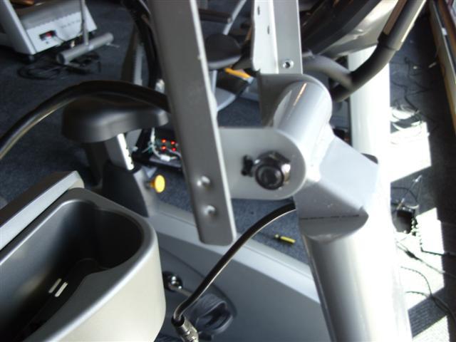
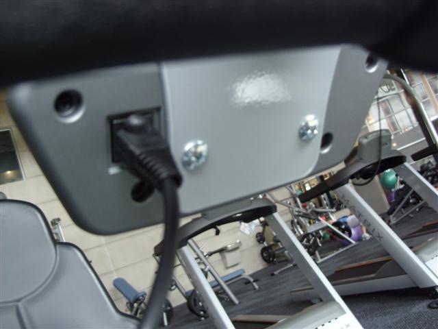
26 chapter 8: part replacement guide 8.1 CONSOLE REPLACEMENT 1) Remove the 4 screws holding the console to the frame (Figure A). 2) Disconnect the console cable, HR connections, and the ground wire from the defective console and remove the console (Figure B). 3) Reinstall the wire connections to the new console. 4) Carefully push the wires into the console and mast until they are clear of the console / mast connection and attach the console to the mast using the 4 screws removed in Step 1. 5) Test the bike for function as outlined in Section Figure A Figure B 22
 Remove the 2 screws")
 Remove the 4 screws holding the heart rate")
.")
 Reverse Steps 1-3 to install a new handlebar.")
27 Chapter 8: Part Replacement Guide 8.2 HANDLEBAR REPLACEMENT 1) Remove the 2 screws holding on the handlebar cover (Figures A & B). 2) Remove the 4 screws holding the heart rate handlebar to the console mast being careful to support the handlebar (Figure C). 3) Remove the defective handlebar (Figure D). 4) Reverse Steps 1-3 to install a new handlebar. Figure A Figure B Figure c figure d 23
 Remove the 2 screws holding the")
 Remove the cup holder (Figure B).")
28 Chapter 8: Part Replacement Guide 8.3 CUP HOLDER REPLACEMENT 1) Remove the 2 screws holding the cup holder to the frame (Figure A). 2) Remove the cup holder (Figure B). 3) Reverse Steps 1-2 to install a new cup holder. Figure A Figure B 24
 Unplug and remove the faulty overlay (Figure B). 4) Clean the console area with alcohol to remove any left over adhesive (Figure C).")
 Push the overlay ribbon cable through the hole in the console and plug it in (Figure F). 8) Match the overlay to the cutout on the console (Figure G).")
29 Chapter 8: Part Replacement Guide 8.4 CONSOLE KEYPAD / OVERLAY REPLACEMENT 1) Remove the console as outlined in Section ) Remove the back cover of the console (Figure A). 3) Unplug and remove the faulty overlay (Figure B). 4) Clean the console area with alcohol to remove any left over adhesive (Figure C). 5) Remove the protective film over the display window of the overlay (Figure D). 6) Peel part of the protective film from the back of the overlay (Figure E). 7) Push the overlay ribbon cable through the hole in the console and plug it in (Figure F). 8) Match the overlay to the cutout on the console (Figure G). 9) Press down on the corners of the overlay to keep it in place, then remove the protective film (Figure H & I). 10) Once the overlay is in the correct position, press down on the overlay with a cloth to adhere it to the console plastic (Figure J). 11) Use the same procedure to replace any additional faulty overlays. NOTE: Overlays can not be reused. 12) Test the Bike for function as outlined in Section Figure A Figure B Figure C Figure D 25


30 Chapter 8: Part Replacement Guide 8.4 CONSOLE KEYPAD / OVERLAY REPLACEMENT - CONTINUED Figure E Figure F Figure G Figure H figure i figure j 26
 Lift up the rubber boot at the bottom of the console mast (Figure A), and remove the 4 screws holding the console mast to the frame (Figure B).")
 When installing a new console mast, be sure to pull the console wires up through the new mast prior to installing the 4 screws into the frame.")
31 Chapter 8: Part Replacement Guide 8.5 console mast removal 1) Remove the console as outlined in Section ) Remove the HR handlebars as outlined in Section ) Lift up the rubber boot at the bottom of the console mast (Figure A), and remove the 4 screws holding the console mast to the frame (Figure B). 4) Pull the wires out the bottom of the console mast and remove the mast (Figure C). 5) When installing a new console mast, be sure to pull the console wires up through the new mast prior to installing the 4 screws into the frame. 6) Test the bike for function as outlined in Section Figure A Figure B 27
 Remove the 4 screws holding the seat")
 Lift the seat pad away from the seat frame (Figure B).")
32 Chapter 8: Part Replacement Guide 8.6 seat pad replacement 1) Remove the 4 screws holding the seat pad to the seat frame (Figure A). 2) Lift the seat pad away from the seat frame (Figure B). 3) Reverse Steps 1-2 to install a new seat pad. Figure A Figure B 28
 Remove the 8 screws holding the")
.")
. 3) Remove the back pad (Figure C).")
33 Chapter 8: Part Replacement Guide 8.7 back pad Replacement 1) Remove the 8 screws holding the plastic cover onto the back of the seat pad and remove it (Figure A). 2) Remove the 4 screws holding the back pad onto the seat frame (Figure B). 3) Remove the back pad (Figure C). 4) Reverse Steps 1-3 to install a new back pad. Figure A Figure B Figure C 29
 Remove the back pad as outlined in Section 8.7. 3) Disconnect the heart rate wiring exposed when the seat pad is removed (Figure A).")
 Remove the heart rate handlebars from the frame (Figure C). 6) Reverse Steps 1-5 to install a new heart rate handlebar.")
34 Chapter 8: Part Replacement Guide 8.8 Heart rate handlebar replacement 1) Remove the seat pad as outlined in Section ) Remove the back pad as outlined in Section ) Disconnect the heart rate wiring exposed when the seat pad is removed (Figure A). 4) Remove the 3 screws holding the heart rate handlebars to the seat frame (Figure B). 5) Remove the heart rate handlebars from the frame (Figure C). 6) Reverse Steps 1-5 to install a new heart rate handlebar. 7) Test the bike for function as outlined in Section figure a figure b figure c 30
 Remove the 3 screws holding")
 Pull the 2 halves of the HR grip apart (Figure B).")
.")
.")
35 Chapter 8: Part Replacement Guide 8.9 heart Rate Grips Replacement 1) Remove the 3 screws holding the HR grip together (Figure A). 2) Pull the 2 halves of the HR grip apart (Figure B). 3) Disconnect the black wire and remove the lower portion of the HR grip (Figure C). 4) Disconnect the red wire and level button and remove the upper portion of the HR grip (Figure D). 5) Reverse Steps 1-4 to install new HR grips. 6) Test the bike for function as outlined in Section figure a figure b figure c figure d 31
36 Chapter 8: Part Replacement Guide 8.10 UPper seat frame replacement 1) Remove the seat pad as outlined in Section ) Remove the back pad as outlined in Section ) Disconnect and remove the HR handlebar as outlined in Section ) Remove the 4 screws holding the upper seat frame to the lower seat frame (Figure A). 5) Remove the upper seat frame from the lower seat frame (Figure B). 6) Reverse Steps 1-5 to install a new seat frame. 7) Test the bike for function as outlined in Section figure a figure b 32
 Remove the 2 screws holding the seat position plate onto the seat frame and remove the seat position plate (Figures A & B).")
 Remove the 4 screws holding the upper seat frame onto the lower seat frame and remove the upper seat frame (Figures E & F).")
 Remove the 2 screws holding the rear end cap onto the seat track and remove the end cap (Figures H & I).")
37 Chapter 8: Part Replacement Guide 8.11 lower seat frame replacement 1) Remove the seat pad as outlined in Section ) Remove the back pad as outlined in Section ) Remove the 2 screws holding the seat position plate onto the seat frame and remove the seat position plate (Figures A & B). 4) Disconnect the HR wiring that is exposed when the seat pad is removed and slide it out the hole in the frame so it does not restrict the seat movement (Figures C & D). 5) Remove the 4 screws holding the upper seat frame onto the lower seat frame and remove the upper seat frame (Figures E & F). 6) Remove the screw holding the rear seat roller to the seat track and remove the roller (Figure G). 7) Remove the 2 screws holding the rear end cap onto the seat track and remove the end cap (Figures H & I). 8) Depress the seat position lever and pull the lower seat frame off of the seat track (Figure J). 9) Reverse Steps 1-8 to install a new lower seat frame. 10) Test the bike for function as outlined in Section figure a figure b figure c figure d 33


38 Chapter 8: Part Replacement Guide 8.11 lower seat frame replacement - continued figure e figure f figure g figure h figure i figure j 34
 Remove the 2 screws holding the seat")
 Remove the seat adjustment handle (Figure B).")
39 Chapter 8: Part Replacement Guide 8.12 seat adjustment handle replacement 1) Remove the 2 screws holding the seat adjustment handle to the seat frame (Figure A). 2) Remove the seat adjustment handle (Figure B). 3) Reverse Steps 1-2 to install a new seat adjustment handle. 4) Test the bike for function as outlined in Section figure a figure b 35
 Remove the 8 screws holding the")
.")
.")
40 Chapter 8: Part Replacement Guide 8.13 rear shroud removal 1) Remove the 8 screws holding the right side shroud to the frame and left shroud and remove it (Figure A). 2) Remove the 6 screws holding the left side shroud to the frame and remove it (Figure B). 3) Figure C shows the bike with both rear shrouds removed. Figure A Figure B Figure C 36
 Use a 15 mm wrench to remove the pedal from the crank (Figure A).")
.")
41 Chapter 8: Part Replacement Guide 8.14 Pedal replacement 1) Use a 15 mm wrench to remove the pedal from the crank (Figure A). NOTE: For the right side pedal, the threads are normal. For the left side pedal, the threads are reversed (the pedal turns off counterclockwise). 2) Remove the pedal (Figure B). 3) Reverse Steps 1-2 to install a new pedal. Figure A Figure B 37
 Remove the 9 screws holding the right side front shroud to the frame and the left shroud and remove it")
 Remove the 5 screws holding the left side front shroud to the frame and remove it (Figure B).")
42 Chapter 8: Part Replacement Guide 8.15 front Shroud removal 1) Remove the pedals as outlined in Section ) Remove the 9 screws holding the right side front shroud to the frame and the left shroud and remove it (Figure A). NOTE: You will need to angle the shrouds so that the crank passes through the hole in the shroud. 3) Remove the 5 screws holding the left side front shroud to the frame and remove it (Figure B). figure a figure b 38
 Remove the rear shrouds as outlined in Section 8.13.")
 Remove the 2 screws holding the lower board to the frame (Figure B), and remove the lower board.")
43 Chapter 8: Part Replacement Guide 8.16 LOWER CONTROL BOARD REPLACEMENT 1) Remove the rear shrouds as outlined in Section ) Disconnect the 3 wire connections to the lower board (Figure A). 3) Remove the 2 screws holding the lower board to the frame (Figure B), and remove the lower board. 4) Reverse Steps 1-3 to install a new lower board. 5) Test the bike for function as outlined in Section figure a figure b 39
 Remove the right side front shroud as outlined")
 Remove the screw that applies tension to the belt (Figure A).")
. 4) Remove the belt (Figure C).")

44 Chapter 8: Part Replacement Guide 8.17 DRIVE BELT REPLACEMENT 1) Remove the right side front shroud as outlined in Section ) Remove the screw that applies tension to the belt (Figure A). 3) Rotate the tension assembly to remove the tension from the belt (Figure B). 4) Remove the belt (Figure C). 5) Reverse Steps 1-4 to install a new drive belt. NOTE: Be sure to reattach the tension spring. If more tension is needed on the drive belt, multiple holes are available for the spring attachment (Figure D). 6) Test the bike for function as outlined in Section figure a figure b figure c figure d 40
45 Chapter 8: Part Replacement Guide 8.18 GENERATOR BELT REPLACEMENT 1) Remove the front shrouds as outlined in Section ) Loosen the nuts holding the Generator to the frame (Figure A), and remove the nuts putting tension on the Generator belt (Figure B). 3) Once the tension has been removed, the Generator belt can be walked off of the pulley (Figure C). 4) Pull the Generator out of the frame towards the front of the unit, and remove the Generator belt (Figure D). 5) Reverse Steps 1-4 to install a new Generator belt. NOTE: Re-tension the new Generator belt to 85 ft / lbs. 6) Test the bike for function as outlined in Section figure a figure b figure c figure d 41
 Remove the nuts holding the Generator to the frame (Figure A), and remove the nuts putting tension on the Generator belt (Figure B).")
46 Chapter 8: part replacement guide 8.19 Generator replacement 1) Remove the front shrouds as outlined in Section ) Remove the nuts holding the Generator to the frame (Figure A), and remove the nuts putting tension on the Generator belt (Figure B). 3) Once the tension has been removed, the Generator belt can be walked off of the pulley (Figure C). 4) Pull the Generator out of the frame towards the front of the unit, and remove the Generator belt (Figure D). 5) Reverse Steps 1-4 to install a new Generator. 6) Test the bike for function as outlined in Section figure a figure b figure c figure d 42
47 Chapter 8: part replacement guide 8.20 pulley axle set replacement 1) Remove the front shrouds as outlined in Section ) Remove the drive belt as outlined in Section ) Loosen the nuts holding the Generator to the frame (Figure A), and remove the nuts putting tension on the Generator belt (Figure B). 4) Once the tension has been removed, walk the Generator belt off of the pulley (Figure C). 5) Remove the C-clip holding the bearing in place on the right side of the frame (Figure D). 6) Remove the bearing (Figure E). 7) Remove the large nut holding in the pulley axle assembly with a large channel lock pliers or a pipe wrench (Figure F). 8) Once the large nut is removed, the pulley axle set can be removed from the left side of the frame (Figure G). 9) Reverse Steps 1-8 to install a new pulley axle set. 10) Test the bike for function as outlined in Section figure a figure b figure c 43


48 Chapter 8: part replacement guide 8.20 pulley axle set Replacement - continued figure D Figure E Figure F FIgure G 44
 Remove the front shrouds as outlined in Section 8.15.")
 Remove the 3 screws holding the crank axle bearings in place on both sides (Figure A).")
 Use a 32 mm wrench to remove the crank axle nuts (Figure C). NOTE: This nut is reverse threaded.")
49 Chapter 8: Part Replacement Guide 8.21 crank axle set replacement 1) Remove the front shrouds as outlined in Section ) Remove the drive belt as outlined in Section ) Remove the 3 screws holding the crank axle bearings in place on both sides (Figure A). 5) Bend the tabs of the nut on the left side of the frame so that this nut will turn (Figure B). 6) Use a 32 mm wrench to remove the crank axle nuts (Figure C). NOTE: This nut is reverse threaded. 7) Once the nuts are removed, the crank axle can be removed from the right side of the frame. 8) Reverse Steps 1-7 to install a new crank axle set. 9) Test the bike as outlined in Section Figure A Figure B figure c 45
50 Chapter 8: Part Replacement Guide 8.22 Testing the BIKE Once the unit or replacement part is fully installed and assembled and properly placed on the floor, use the following instructions to setup and test the machine: 1) Check that the console is set for bike. a. Press and hold both LEVEL keys until Manager Mode appears on the display and press SELECT. b. Use the UP or DOWN LEVEL keys to scroll to Machine. c. Press SELECT when the display says Machine and make sure it is set for Bike (BI). d. If Machine is not set for Bike (BI), change to BI using the UP or DOWN LEVEL key and press START to save. e. Press the START key twice to return to normal function. 2) Without hitting start or entering any program modes, sit on the bike and hold the handlebars while pedaling to simulate exercising. While moving, listen for any odd noises or squeaks. 3) After stopping movement, press the START key and begin pedaling. 4) Grasp the hand grips to check for proper heart rate response. 5) Press the level up and down buttons on the console and hand grips to make sure resistance is fully functional. 6) If everything functions properly, stop pedaling and the unit will reset to normal operation within 30 seconds. 46
51 Chapter 9: bike Specifications and Assembly Guide 9.1 R3x-01 BIKE SPECIFICATIONS Specifications Display Type Programs Resistance Levels 25 Coaxial Cable Connection AC TV Power Connection Monitor Mount Resistance Type Power Requirements0 Overall Dimensions (L x W x H) Maximum User Weight Unit Weight Transport Wheel Dot-Matrix LED Manual, Rolling, Intervals, Fat Burn, Random, Fitness Test, Target HR, Constant Watts Yes Yes Yes Generator Self Powered 64" x 29" x 51" / x 73.5 x cm 400 lbs / kg 170 lbs / 77 kg Yes 47
52 Chapter 9: bike Specifications and assembly guide 9.2 Fasteners and Assembly Tools quantity part # sketch description notes 1 z05 4 mm allen wrench purple 1 z04 5mm allen wrench purple 1 z01 6 mm allen wrench purple 1 z03 open wrench (15 & 17 mm) purple 1 z02 #2 phillips screwdriver purple 4 Z11 hex head screw (M8 x 25L) white 4 Z12 spring washer white 2 Z13 button head screw (m5 x 10L) white 8 Z21 hex head screw (M5 x 20l) black 8 Z22 flat washer black 8 z23 See sketch of part Z12 spring washer black 4 z31 button head screw (M8 x 15L) yellow 4 z32 See sketch of part Z22 flat washer yellow 4 z33 See sketch of part Z12 spring washer yellow 2 z34 See sketch of part Z11 hex head screw (M8 x 25L) yellow 3 Z41 See sketch of part Z31 button head screw (M8 x 15l) red 4 Z42 see sketch of part Z31 button head screw (m8 x 50L) red 4 Z43 See sketch of part Z22 arc washer red 4 Z44 See sketch of part Z12 spring washer red 3 Z45 See sketch of part Z31 button head screw (m8 x 15l) red 1 Z51 adjustment foot 48
53 Chapter 9: bike SPECIFICATIONS AND ASSEMBLY GUIDE 9.3 ASSEMBLY INSTRUCTIONS after these assembly steps are complete, be sure to setup and test the unit as outlined in section step 1 49
54 Chapter 9: bike SPECIFICATIONS AND ASSEMBLY GUIDE 9.3 Assembly Instructions - Continued step 2 50
55 Chapter 9: bike SPECIFICATIONS AND ASSEMBLY GUIDE 9.3 Assembly Instructions - Continued step 3 51
56 Chapter 9: bike SPECIFICATIONS AND ASSEMBLY GUIDE 9.3 Assembly Instructions - Continued step 4 52
57 Chapter 9: bike specifications and assembly guide 9.3 ASSEMBLY INSTRUCTIONS - CONTINUED Step 5 53
58 Chapter 9: bike SPECIFICATIONS AND ASSEMBLY GUIDE 9.3 assembly instructions - continued final assembly 54

59 Chapter 9: Bike specifications and assembly guide 9.4 Adjusting the pedal straps and SEAT Adjusting the pedal straps The straps are designed to fit your individual foot size and should be adjusted tight enough to keep your foot from slipping. The pedals include spring loaded clips for easy adjustment. To tighten the strap, pull down the open end of the strap. To loosen the strap, push down on the top of the clip and pull the strap up. Release the clip to lock the strap in place. ADJUSTING THE R3x-01 SEAT While seated on the Matrix R3x-01 Bike, an optimum position will allow movement through the bottom of the stroke without locking the knees or shifting in the seat. The knees should have a slight bend at the point of fullest leg extension. If the seat needs to be adjusted, lift the spring loaded seat lever on the right side of the seat to make adjustments. Slide the seat forward or backward to its desired location. Release the spring loaded seat lever and gently attempt to rock forward and backward to assure it is locked in place. Check the seat distance again and re-adjust it if necessary. If the seat is wobbly or loose, tighten the seat roller brackets using the procedure outlined in Section
60 Chapter 9: bike specifications and assembly guide 9.5 LEVELING THE BIKE STABILIZING the MATRIX R3x-01 BIKE After positioning the bike in its intended location, check its stability by attempting to shake it side to side. Shaking or wobbling indicates that your bike needs to be leveled. Determine which leveler is not resting completely on the floor. Loosen the nut with one hand to allow the leveler to rotate. Rotate the left or right leveler, and repeat the adjustment as necessary until the bike is stable. Lock the adjustment by tightening the nut against the rear foot support. 56
 Pound the spring pin (found in the hardware bag) into the small hole in the TV bracket (Figure A). This is much easier to do before the bracket is installed on the bike.")

61 Chapter 9: bike specifications and assembly guide 9.6 TV Bracket installation 1) Remove the bracket, hardware, and TV from their boxes. 2) Pound the spring pin (found in the hardware bag) into the small hole in the TV bracket (Figure A). This is much easier to do before the bracket is installed on the bike. 3) Remove the Matrix Logo plate from the front of the console mast (Figure B). 4) Pull the coax and TV power wires through the hole in the front of the console mast. NOTE: You may need to remove the console to get these wires fished through the hole in the front of the console mast. 5) Attach the coax and TV power wires to the wiring running inside of the TV bracket (Figure C). You will need to use the male to male coax connector shipped in the hardware bag (Figure D). 6) Attach the TV bracket to the console mast using the 4 screws removed in Step 3 (Figure E). 7) Attach both of the long metal pieces (called rabbit ears) to the TV bracket using the long screw and nut found in the hardware bag (Figure F). The user's right side rabbit ear should be installed so that the spring pin lines up with a hole in the rabbit ear to limit the angle of adjustment of the TV (Figure G). 8) Attach the TV to the rabbit ears using 4 screws from the hardware bag (Figure H). 9) Attach the TV controller bracket to the front of the console. The TV controller bracket will mount using the 2 bottom screws holding the console to the console mast (Figure I). 10) Attach the TV controller to the TV controller bracket (Figure J). 11) Connect the TV power wire (Figure K), coax cable signal wire (Figure L), and controller wire (Figure M) to the back of the TV. NOTE: The controller wire will have a tag on both ends, one labeled controller, the other TV. 12) Connect the controller wire to the back of the TV controller (Figure N). 13) Install the cover onto the back of the TV (Figure O). NOTE: There is an extra cover shipped with the TV. 13) Run a coax cable to the base of the bike and plug it into the entertainment port (Figure P). 14) Plug in the TV power adaptor to a wall plug and into the entertainment port at the base of the bike (Figure Q). 15) Use the remote control sent with the TV to perform a channel search to program the TV (Figure R). 16) To perform a channel search, hit MENU, the right arrow once, hit the down arrow to Auto CH Search, and then ENTER. The TV will automatically search for both Analog and Digital channels. Figure A Figure B 57


62 Chapter 9: bike specifications and assembly guide 9.6 TV Bracket installation - continued Figure C Figure D Figure E Figure F Figure G Figure H 58


63 Chapter 9: bike specifications and assembly guide 9.6 TV Bracket installation - continued Figure I Figure J Figure K Figure L Figure M Figure N 59


64 Chapter 9: bike specifications and assembly guide 9.6 TV Bracket installation - continued Figure O Figure P Figure Q Figure R 60
65 NOTES 61
66 MATrix Fitness systems corp Landmark Drive Cottage Grove wi USA TOLL FREE FAX KO REV. 1 62
E3x-01 elliptical Trainer
 E3x-01 elliptical Trainer SERVICE MANUAl chapter 1: Serial Number Location CHAPTER 1: Serial number location... 1 CHAPTER 2: Important Safety instructions 2.1 Read and Save These Instructions... 2 2.2
E5x-02 elliptical Trainer
 E5x-02 elliptical Trainer SERVICE MANUAl table of contents CHAPTER 1: Serial number location... 1 CHAPTER 2: Important Safety instructions 2.1 Read and Save These Instructions... 3 2.2 Electrical Requirements...
IT ALL STARTS WITH A VISION IT ALL STARTS WITH A VISION FITNESS U 6 0 B I K E S E R V I C E M A N U A L
 IT ALL STARTS WITH A VISION IT ALL STARTS WITH A VISION FITNESS U 6 0 B I K E S E R V I C E M A N U A L TABLE OF CONTENTS CHAPTER 1: SERIAL NUMBER LOCATION... 1 CHAPTER 2: IMPORTANT SAFETY INSTRUCTIONS
R 3 X B I K E S E R V I C E M A N U A L
 R 3 X - 0 2 B I K E S E R V I C E M A N U A L TABLE OF CONTENTS CHAPTER 1: SERIAL NUMBER LOCATION... 1 CHAPTER 2: IMPORTANT SAFETY INSTRUCTIONS 2.1 Read and Save These Instructions... 2 2.2 Electrical
E7xE-01 elliptical Trainer
 E7xE-01 elliptical Trainer SERVICE MANUAl Table of contents CHAPTER 1: Serial number location... 1 CHAPTER 2: Important Safety instructions 2.1 Read and Save These Instructions... 3 2.2 Electrical Requirements...
U 3 X B I K E S E R V I C E M A N U A L
 U 3 X - 0 2 B I K E S E R V I C E M A N U A L TABLE OF CONTENTS CHAPTER 1: SERIAL NUMBER LOCATION... 1 CHAPTER 2: IMPORTANT SAFETY INSTRUCTIONS 2.1 Read and Save These Instructions... 3 2.2 Electrical
S-Drive Performance Trainer
 S-Drive Performance Trainer SERVICE MANUAl Table of contents CHAPTER 1: Serial number location... 1 CHAPTER 2: Important Safety instructions 2.1 Read and Save These Instructions... 2 2.2 Before Getting
2.1 Read and Save These Instructions Electrical Requirements... 4
 E5x-03 Suspension elliptical SERVICE MANUAl E5X-04 SUSPENSION ELLIPTICAL SERVICE MANUAl Table of contents CHAPTER 1: Serial number location... 1 CHAPTER 2: Important Safety instructions 2.1 Read and Save
R o w e R ( A R 1 1 ) S e R V I C e M A N U A l
 S e R V I C e M A N U A l") Rower-02 (AR11) SERVICE MANUAl Table of contents CHAPTER 1: Serial number location... 1 CHAPTER 2: Important Safety instructions 2.1 Read and Save These Instructions... 2 2.2 Locating the Unit... 2 2.3
Rower-02 (AR11) SERVICE MANUAl Table of contents CHAPTER 1: Serial number location... 1 CHAPTER 2: Important Safety instructions 2.1 Read and Save These Instructions... 2 2.2 Locating the Unit... 2 2.3
C 5 X C L I M B M I L L S E R V I C E M A N U A L
 C 5 X - 0 1 C L I M B M I L L S E R V I C E M A N U A L TABLE OF CONTENTS CHAPTER 1: SERIAL NUMBER LOCATION... 1 CHAPTER 2: IMPORTANT SAFETY INSTRUCTIONS 2.1 Read and Save These Instructions... 3 2.2 Electrical
A5x-02 Ascent Trainer
 A5x-02 Ascent Trainer SERVICE MANUAl table of contents CHAPTER 1: Serial number location... 1 CHAPTER 2: Important Safety instructions 2.1 Moving the Unit... 3 2.2 Read and Save These Instructions...
Magnetic Elliptical Trainer
 Magnetic Elliptical Trainer ITEM NO.: 400 OWNER S MANUAL IMPORTANT: Read all instructions carefully before using this product. Retain this owner s manual for future reference. The specifications of this
MX-T3x(TM94E) AC SYSTEM SERVICE MANUAL
 AC SYSTEM SERVICE MANUAL") MX-T3x(TM94E) AC SYSTEM SERVICE MANUAL 1 TABLE OF CONTENTS SECTION 1:SERIAL NUMBER LOCATION SECTION 2:MOVING THE UNIT SECTION 3:IMPORTANT SAFETY INSTRUCTIONS SECTION 4:PREVENTATIVE MAINTENANCE 4.1 Maintenance
MX-T3x(TM94E) AC SYSTEM SERVICE MANUAL 1 TABLE OF CONTENTS SECTION 1:SERIAL NUMBER LOCATION SECTION 2:MOVING THE UNIT SECTION 3:IMPORTANT SAFETY INSTRUCTIONS SECTION 4:PREVENTATIVE MAINTENANCE 4.1 Maintenance
ACCORD ELLIPTICAL TRAINER ITEM NO: 93470
 ACCORD ELLIPTICAL TRAINER ITEM NO: 93470 OWNER S MANUAL IMPORTANT: Read all instructions carefully before using this product. Retain this owner s manual for future reference. The specifications of this
T 1 x T r e a d m i l l S e r V i C e m a N U a l
 T1x-04 Treadmill SERVICE MANUAl Table of contents CHAPTER 1: Serial number location... 1 CHAPTER 2: Important Safety instructions 2.1 Before Getting Started... 2 2.2 Read and Save These Instructions...
CARE AND MAINTENANCE INSTRUCTIONS
 STRONG. SMART. BEAUTIFUL. CARE AND MAINTENANCE INSTRUCTIONS In order to maximize life span, and minimize down time, all MATRIX equipment requires regular cleaning, and maintenance items performed on a
T 3 x T r e a d m i l l S e r V i C e m a N U a l
 T3x-05 Treadmill SERVICE MANUAl Table of Contents CHAPTER 1: Serial number location... 1 CHAPTER 2: Important Safety instructions 2.1 Before Getting Started... 2 2.2 Read and Save These Instructions...
OWNERS MANUAL. ULTRA Single-Station Strength G7-S42 Triceps Press
 OWNERS MANUAL ULTRA Single-Station Strength G7-S42 Triceps Press Table Of Contents Safety, General Care & Maintenence... 3 Getting Started (Product Specifications)... 5 Assembly Information... 6 Parts
OWNERS MANUAL. ULTRA Single-Station Strength G7-S34 Seated Row
 OWNERS MANUAL ULTRA Single-Station Strength G7-S34 Seated Row Table Of Contents Safety, General Care & Maintenence...3 Getting Started (Product Specifications)...5 Assembly Information...6 Markings...7
OWNERS MANUAL. ULTRA Single-Station Strength G7-S13 Chest Press
 OWNERS MANUAL ULTRA Single-Station Strength G7-S13 Chest Press Table Of Contents Safety, General Care & Maintenence...3 Getting Started (Product Specifications)...5 Assembly Information...6 Markings...7
Pro Bike 6000 Series
 Pro Bike 6000 Series Preliminary Service Manual June 28, 2004 Pro Bike (6000 Series) Service Manual Table of Contents 1. Preventative Maintenance 2. Display Settings 3. Diagnostic Lights 4. Parts & Diagrams
TABLE OF CONTENTS CHAPTER 1: SAFETY PRECAUTIONS. 2.3 COMPONENTS in the Hardwars Kit COMPONENTS on the Product SETP SETP2...
 TABLE OF CONTENTS CHAPTER : SAFETY PRECAUTIONS. SAFETY PRECAUTIONS... CHAPTER 2: INSTRUCTIONS 2. DIMENSIONS... 2.2 LIST OF PARTS... 2.3 COMPONENTS in the Hardwars Kit.... 2.4 COMPONENTS on the Product...
XINGGUI Elliptical Cross Trainer
 XINGGUI Elliptical Cross Trainer ITEM NO.: 93040 OWNER S MANUAL IMPORTANT: Read all instructions carefully before using this product. Retain this owner s manual for future reference. The specifications
2013 Elite T4000 (TM461C) Service Manual
 Service Manual") 2013 Elite T4000 (TM461C) Service Manual 1 TABLE OF CONTENTS CHAPTER 1: SERIAL NUMBER LOCATION...3 CHAPTER 2: PREVENTATIVE MAINTENANCE 2.1 Preventative Maintenance. 4 2.2 Tension and Centering the Running
2013 Elite T4000 (TM461C) Service Manual 1 TABLE OF CONTENTS CHAPTER 1: SERIAL NUMBER LOCATION...3 CHAPTER 2: PREVENTATIVE MAINTENANCE 2.1 Preventative Maintenance. 4 2.2 Tension and Centering the Running
ASSEMBLY MANUAL 9GU - COMMERCIAL UPRIGHT BIKE
 ASSEMBLY MANUAL 9GU - COMMERCIAL UPRIGHT BIKE IMPORTANT SAFETY INSTRUCTIONS Read this Owner s Manual and follow it s instructions carefully before using the machine. Make sure that it is properly assembled
A935 OWNER'S MANUAL ASSEMBLY INSTRUCTIONS
 2013.02 A935 OWNER'S MANUAL ASSEMBLY INSTRUCTIONS A. SAFETY INSTRUCTIONS Read all cautions/warnings and obtain proper instruction on use of the machines prior to using. Use appropriate positioning and
table of contents 3.1 Legal Disclaimer Training Notice Read and Save These Instructions Electrical Requirements...
 Ascent Trainer SERVICE MANUAl table of contents CHAPTER 1: Serial number location... 1 CHAPTER 2: Moving the unit... 2 CHAPTER 3: Important Safety instructions 3.1 Legal Disclaimer... 3 3.2 Training Notice...
OWNERS MANUAL MODEL ECT-2100 ELLIPTICAL CROSSTRAINER
 OWNERS MANUAL MODEL ECT-00 ELLIPTICAL CROSSTRAINER QUESTION? As a quality home gym supplier we are committed to your complete satisfaction. If you have questions, or find missing or damaged parts, we will
ASSEMBLY INSTRUCTIONS / OWNERS MANUAL AIR BIKE AB-1
 AIR BIKE AB- ASSEMBLY INSTRUCTIONS / OWNERS MANUAL IMPORTANT : READ ALL ASSEMBLY INSTRUCTIONS AND SAFETY PRECAUTIONS BEFORE USING THIS PRODUCT. REFERENCE ALL SAFETY GUIDELINES AND WARNING LABELS. RETAIN
T & T Service Manual
 T101-04 & T202-03 Service Manual 1 2 3 Contents CHAPTER 1: SERIAL NUMBER LOCATION... 6 CHAPTER 2: PREVENTATIVE MAINTENANCE 2.1 Preventative Maintenance... 8 2.2 Tension and Centering the Running Belt...
OWNERS MANUAL. Versa Single-Station Strength VS-S33 Lat Pulldown
 OWNERS MANUAL Versa Single-Station Strength VS-S33 Lat Pulldown Table Of Contents Safety, General Care & Maintenence...3 Getting Started (Product Specifications)...5 Assembly Information...6 Parts List...7
OWNERS MANUAL. Versa Single-Station Strength VS-S53 Abdominal
 OWNERS MANUAL Versa Single-Station Strength VS-S53 Abdominal Table Of Contents Safety, General Care & Maintenence... 3 Getting Started (Product Specifications)... 5 Assembly Information... 6 Markings...
LS10.0T Service Manual
 LS10.0T Service Manual 1 TABLE OF CONTENTS CHAPTER 1: SERIAL NUMBER LOCATION...3 CHAPTER 2: PREVENTATIVE MAINTENANCE 2.1 Preventative Maintenance. 4 2.2 Tension and Centering the Running Belt....6 CHAPTER
EASY ADJUSTABLE SEAT RECUMBENT BIKE
 EASY ADJUSTABLE SEAT RECUMBENT BIKE SF-RB4616 USER MANUAL IMPORTANT! Please retain owner s manual for maintenance and adjustment instructions. Your satisfaction is very important to us, PLEASE DO NOT RETURN
SPACE SAVING FOLDING TREADMILL SF-T7632 USER MANUAL
 SPACE SAVING FOLDING TREADMILL SF-T7632 USER MANUAL IMPORTANT: Read all instructions carefully before using this product. Retain owner s manual for future reference. For customer service, please contact:
LS8.0T Service Manual
 LS8.0T Service Manual 1 TABLE OF CONTENTS CHAPTER 1: SERIAL NUMBER LOCATION...3 CHAPTER 2: PREVENTATIVE MAINTENANCE 2.1 Preventative Maintenance. 4 2.2 Tension and Centering the Running Belt....6 CHAPTER
PaceMaster Bronze XRC
 PaceMaster Bronze XRC OWNER S MANUAL Aerobics Inc., 34 Fairfield Place West Caldwell, NJ 07006, (973) 276-9700 www.pacemaster.com Part # BRONZE XRC Rev. 11/13/07 1 TABLE OF CONTENTS INTRODUCTION 3 IMPORTANT
G3-MS20 G3-MS40 G3-MS24 G3-MS51 G3-MS52 G3-MS53 G3-MS50 G3-MS80 AURA SERIES
 AURA SERIES G3-MS G3-MS5 G3-MS5 G3-MS53 G3-MS0 G3-MS0 G3-MS50 G3-MS80 IMPORTANT SAFETY INFORMATION It is the sole responsibility of the purchaser of MATRIX products to instruct all individuals, whether
SF-T7610 TREADMILL USER MANUAL
 SF-T7610 TREADMILL USER MANUAL IMPORTANT: Read all instructions carefully before using this product. Retain owner s manual for future reference. For customer service, please contact: support@sunnyhealthfitness.com
RECUMBENT BIKE IMPORTANT: Read all instructions carefully before using this product. Retain this
 RECUMBENT BIKE IMPORTANT: Read all instructions carefully before using this product. Retain this owner s manual for future reference. The specifications of this product may vary from this photo, subject
EASY ASSEMBLY FOLDING TREADMILL SF-T7610 USER MANUAL
 EASY ASSEMBLY FOLDING TREADMILL SF-T7610 USER MANUAL IMPORTANT! Please retain owner s manual for maintenance and adjustment instructions. Your satisfaction is very important to us, PLEASE DO NOT RETURN
MARCY Elliptical Machine PL-21930
 NOTE: Please read all instructions carefully before using this product Table of Contents Safety Notice Hardware Identifier MARCY Elliptical Machine PL-21930 Assembly Instruction Parts List Computer Warranty
TABLE OF CONTENTS 1. IMPORTANT SAFETY INSTRUCTIONS 3 2. CARE INSTRUCTIONS 4 3. ASSEMBLY INSTRUCTIONS 5 4. COMPUTER OPERATION 12 5.
 E-1 OWNER S MANUAL Product may vary slightly from the item pictured due to model upgrades Read all instructions carefully before using this product. Retain this owner s manual for future reference. NOTE:
USER MANUAL - EN IN 8244 Recumbent insportline Varis
 USER MANUAL - EN IN 8244 Recumbent insportline Varis 1 CONTENTS IMPORTANT SAFETY INSTRUCTIONS... 3 OVERVIEW DRAWING... 4 PARTS LIST... 5 HARDWARE PACKING LIST... 7 TOOLS... 7 ASSEMBLY INSTRUCTIONS... 8
Pro Stepper Service Manual
 Pro Stepper Service Manual Table of Contents Table of Contents... 0 Display Panel... 1 Preventive Maintenance... 2 Preventive Maintenance Cont d... 3 Settings - Maintenance Mode... 4 Settings - Maintenance
WALKING TREADMILL SF-T1407M USER MANUAL
 WALKING TREADMILL SF-T1407M USER MANUAL IMPORTANT! Please retain owner s manual for maintenance and adjustment instructions. Your satisfaction is very important to us, PLEASE DO NOT RETURN UNTIL YOU HAVE
202 Schwinn Recumbent Exercise Bike
 202 Schwinn Recumbent Exercise Bike Parts List Full Size Hardware Chart Product Illustration Assembly Instructions 202 Recumbent Exercise Bike IMPORTANT PRECAUTIONS WARNING: To reduce the risk of serious
Foldable Semi-Recumbent Bike
 Foldable Semi-Recumbent Bike IMPORTANT: Read all instructions carefully before using this product. Retain this owner s manual for future reference. The specifications of this product may vary from this
FitBike 1 DBT. Instructions / Manual / Maintenance
 FitBike 1 DBT Instructions / Manual / Maintenance SAFETY PRECAUTIONS Please read all instructions carefully before using this product. Retain this manual for future reference. The specifications of this
PRO INDOOR CYCLING BIKE
 PRO INDOOR CYCLING BIKE SF-B901 USER MANUAL IMPORTANT! Please retain owner s manual for maintenance and adjustment instructions. Your satisfaction is very important to us, PLEASE DO NOT RETURN UNTIL YOU
AIR ELLIPTICAL OWNER S MANUAL. Item #1308
 AIR ELLIPTICAL IMPORTANT: Read all instructions carefully before using this product. Retain this owner s manual for future reference. The specifications of this product may vary from this photo and, subject
MARCY Recumbent Bike PL-960
 NOTE: Please read all instructions carefully before using this product Table of Contents Safety Notice Hardware Identifier MARCY Recumbent Bike PL-960 Assembly Instruction Parts List Computer Warranty
Air Elliptical OWNER S MANUAL. Item #1301
 Air Elliptical IMPORTANT: Read all instructions carefully before using this product. Retain this owner s manual for future reference. The specifications of this product may vary from this photo, subject
Performance Tech Support 1(800)
") 05_MillenniumFluidForce/INS.qk 7/19/05 1:5 PM Page 1 Performance Tech Support 1(800)553-834 Performance, Inc. One Performance Way Chapel Hill, N.C. 7514 1-800-77-453 Made in China www.performancebike.com
05_MillenniumFluidForce/INS.qk 7/19/05 1:5 PM Page 1 Performance Tech Support 1(800)553-834 Performance, Inc. One Performance Way Chapel Hill, N.C. 7514 1-800-77-453 Made in China www.performancebike.com
SX1000 Service Manual SALES: CUSTOMER SERVICE:
 SX1000 Service Manual SALES: 800-278-3933 CUSTOMER SERVICE: 800-745-1373 Revision: August 1999 Table of Contents Section Page I. Overview 2 II. Troubleshooting Tables 3 III. Maintenance Procedures Procedure
BRF 700 BRF 701. Fan Bike OWNER S MANUAL. * This item is for consumer use only and it is not meant for commercial use.
 BRF 700 Fan Bike BRF 701 * This item is for consumer use only and it is not meant for commercial use. OWNER S MANUAL General Information Safety Before you undertake any exercise program, please be sure
SUNNY PRO INDOOR CYCLING BIKE
 SUNNY PRO INDOOR CYCLING BIKE SF-B901 USER MANUAL IMPORTANT! Please retain owner s manual for maintenance and adjustment instructions. Your satisfaction is very important to us, PLEASE DO NOT RETURN UNTIL
GFTMB GFTVRT GFTFS GFTWM GFTEXP GFTLM GFTCB GFTHB CONNEXUS
 CONNEXUS GFTFS GFTWM GFTEXP GFTLM GFTMB GFTVRT GFTCB GFTHB IMPORTANT SAFETY INFORMATION It is the sole responsibility of the purchaser of MATRIX products to instruct all individuals, whether they are the
BELT DRIVE PRO INDOOR CYCLING BIKE SF-B901B USER MANUAL
 BELT DRIVE PRO INDOOR CYCLING BIKE SF-B901B USER MANUAL IMPORTANT! Please retain owner s manual for maintenance and adjustment instructions. Your satisfaction is very important to us, PLEASE DO NOT RETURN
Group Exercise Elliptical OWNER S MANUAL. Please carefully read this entire manual before operating your group exercise elliptical!
 Group Exercise Elliptical OWNER S MANUAL Please carefully read this entire manual before operating your group exercise elliptical! TABLE OF CONTENTS Important Safety Instructions.. 2 Features.... 3 Assembly
ONE YEAR LIMITED WARRANTY
 TABLE OF CONTENTS ONE YEAR LIMITED WARRANTY Warranty 1 Overview Drawing 3 Parts List 4 Hardware List 7 Assembly Instructions 9 How to Fold-Up the Extrusion 14 How to Fold-Down the Extrusion 15 Adjustment
RECUMBENT BIKE WITH ARM EXERCISER
 RECUMBENT BIKE WITH ARM EXERCISER SF-RB4631 USER MANUAL IMPORTANT! Please retain owner s manual for maintenance and adjustment instructions. Your satisfaction is very important to us, PLEASE DO NOT RETURN
EXERPEUTIC TF2000 Fitness Walking and Rehab Treadmill
 hh EXERPEUTIC TF2000 Fitness Walking and Rehab Treadmill IMPORTANT: Read all instructions carefully before assembling and/or using this product. Retain this owner s manual for future reference. The specifications
MAGNETIC RECUMBENT BIKE
 MAGNETIC RECUMBENT BIKE SF-RB4417 USER MANUAL IMPORTANT: Please read this manual carefully before using the product. Retain owner s manual for future reference. For Customer Service, please contact: support@sunnyhealthfitness.com
10 Series Exercise Bike
 10 Series Exercise Bike Nautilus Bowflex Schwinn Fitness StairMaster Universal Nautilus Institute 001-7213-112008B Table of Contents Product Specifications...2 Safety Warnings...3 Exploded Drawing...4
TC1000 Service Manual SALES: CUSTOMER SERVICE:
 TC1000 Service Manual SALES: 800-278-3933 CUSTOMER SERVICE: 800-745-1373 Table of Contents Section Page I. Overview 2 II. Troubleshooting Tables 3 III. Maintenance Procedures Procedure 1 Removal and Reinstallation
G1 STRENGTH 3-STACK MULTI-GYM
 G STRENGTH 3-STACK MULTI-GYM IMPORTANT SAFETY INFORMATION It is the sole responsibility of the purchaser of MATRIX Fitness Systems products to instruct all individuals, whether they are the end user or
CLUB SERIES HIP AB/ADDUCTOR
 CLUB SERIES HIP AB/ADDUCTOR ASSEMBLY INSTRUCTIONS Part # 718601 Rev E 1 Revision: 1/2/03 KEY PART # DESCRIPTION QTY KEY PART # DESCRIPTION QT Y 1 71710xx TOWER 1 22 3102915 3/8 X 3-1/ BOLT 2 1A 6692601
BELT DRIVE INDOOR CYCLING BIKE
 BELT DRIVE INDOOR CYCLING BIKE SF-B1002 USER MANUAL IMPORTANT: Read all instructions carefully before using this product. Retain owner s manual for future reference. For customer service, please contact:
Magnetic Rowing Machine with Aluminum Slide Rail User Manual RW026 USER MANUAL
 Magnetic Rowing Machine with Aluminum Slide Rail User Manual MODEL NO.: RW026 IMPORTANT! Read all instructions carefully before using this product. Save this manual for future reference. EXERCISE EQUIPMENT
Preventative Maintenance and Diagnostics
 Preventative Maintenance and Diagnostics JUNE 2016 Please Read Before You Begin IMPORTANT Before working on any Octane Fitness product, please take the time to look through the product specific manuals.
Cybex Arc Trainer Owner s & Service Manual. 7 - Service
 7 - Service Table of Contents......... iii Warnings/Cautions All warnings and cautions listed in this chapter are as follows:! WARNING: All maintenance activities shall be performed by qualified personnel.
Marsh Shipping Supply Co. LLC. Marsh TD2100 Electric Taper Technical Manual
 Marsh Shipping Supply Co. LLC Marsh TD2100 Electric Taper Technical Manual 2 A wall-socket must be close to the product and readily accessible. The overall system is protected against overload by the branch
AIR MAGNETIC ROWER SF-RW5623 USER MANUAL
 AIR MAGNETIC ROWER SF-RW5623 USER MANUAL IMPORTANT: Read all instructions carefully before using this product. Retain owner s manual for future reference. For customer service, please contact: support@sunnyhealthfitness.com
FULL MOTION ROWING MACHINE SF-RW5639 USER MANUAL
 FULL MOTION ROWING MACHINE SF-RW5639 USER MANUAL IMPORTANT! Please retain owner s manual for maintenance and adjustment instructions. Your satisfaction is very important to us, PLEASE DO NOT RETURN UNTIL
Manual Treadmill with Pulse
 Manual Treadmill with Pulse V1.0-082715 OWNER S MANUAL Item #1005 TABLE OF CONTENTS SERVICE ------------------------------------------------------------------------ 2 IMPORTANT LABELS --------------------------------------------------------
Check the wires going to the back of the computer, if the wires are secure and console will not start see step b.
 ELECTRONIC TROUBLESHOOTING 1. PROBLEM: Console LED's will not light, console will not power up The bike must be pedaled at greater than 50 RPM while Check the wires going to the back of the computer, if
Service Manual ISO7000R Recumbent Bike
 Service Manual ISO7000R Recumbent Bike Before Using this product, read this manual and follow all safety rules and operating instructions. Maintenance The ISO7000R is virtually maintenance free. After
Bowflex Max Trainer M8 / M8i. Service Manual
 Table of Contents Bowflex Max Trainer M8 / M8i Service Manual Section Code Section Page Number 1 Important Safety Instructions 2 1 Safety Warning Labels and Serial Number 3 1 Specifications 4 1 Moving
Matrix IC3. model no.: IC-MXIC3B-01 ENG ESP
 Matrix IC3 model no.: IC-MXIC3B-01 Manufactured by: Indoorcycling Group GmbH Happurger Str. 86 90482 Nuremberg Germany www.indoorcycling.com info@indoorcycling.com MATRIX Fitness Systems Corp. 1610 Landmark
C554i Elliptical Fitness Crosstrainer
 C554i Elliptical Fitness Crosstrainer Warning: This service manual is for use by Precor trained service providers only. If you are not a Precor Trained Servicer, you must not attempt to service any Precor
T611 Repair Manual (Electronics)
") T611 Repair Manual (Electronics) Table of Contents 1-1-1. Product Picture T611 1-2-1. Overlay T611 1-3-1. Component Placement T611 Display Board 1-3-2. Component Placement T611 Lower Compartment 1-4-1.
T611 Repair Manual (Electronics) Table of Contents 1-1-1. Product Picture T611 1-2-1. Overlay T611 1-3-1. Component Placement T611 Display Board 1-3-2. Component Placement T611 Lower Compartment 1-4-1.
Large Tricycle (Wrangler) R140 Product Manual
 R140 Product Manual") Large Tricycle (Wrangler) R140 Product Manual Contents Warnings and Important Information 3 Recommended Use 4 User and Item Dimensions 4 Checking Your Order 4 The Frame 5 The Handlebar and Handbrake 6
Large Tricycle (Wrangler) R140 Product Manual Contents Warnings and Important Information 3 Recommended Use 4 User and Item Dimensions 4 Checking Your Order 4 The Frame 5 The Handlebar and Handbrake 6
Owner s Manual. 4 Functional Trainer. Serial Number Here. Date of Purchase
 Revision 2 June 2014 Functional Trainer Owner s Manual Serial Number Here Date of Purchase www.batcafitness.com 1207 New Hope Road, Raleigh, NC - 919.255.1233 Fusion - www.batcafitness.com 4 Functional
C542i Elliptical Fitness Crosstrainer
 C542i Elliptical Fitness Crosstrainer Warning: This service manual is for use by Precor trained service providers only. If you are not a Precor Trained Servicer, you must not attempt to service any Precor
C524, C524i Elliptical Fitness Crosstrainer
 C524, C524i Elliptical Fitness Crosstrainer Warning: This service manual is for use by Precor trained service providers only. If you are not a Precor Trained Servicer, you must not attempt to service any
Air Elliptical equipment
 Air Elliptical equipment IMPORTANT: Read all the instructions carefully before using this product. Retain this owner s manual for future reference. The specifications of this product may vary from this
CROSS TRAINING MAGNETIC RECUMBENT BIKE
 CROSS TRAINING MAGNETIC RECUMBENT BIKE SF-RB4708 USER MANUAL IMPORTANT! Please retain owner s manual for maintenance and adjustment instructions. Your satisfaction is very important to us, PLEASE DO NOT
FIT SERIES FIT-3 W/ LEG PRESS
 FIT SERIES FIT-3 W/ LEG PRESS ASSEMBLY INSTRUCTIONS Part # 734820 Rev C. Revision:4/04/03 KEY 2 3 4 5 6 7 8 9 0 2 3 4 5 6 7 8 9 20 2 22 23 24 25 26 27 28 29 30 3 32 33 34 35 36 37 38 39 40 4 42 PART #
RBK 815 Recumbent Cycle. RBK 815 Bicycle
 RBK 815 Bicycle Warning: This service manual is for use by Precor trained service providers only. If you are not a Precor Trained Servicer, you must not attempt to service any Precor Product; Call your
C556, C556i Navy Elliptical Fitness Crosstrainer
 C556, C556i Navy Elliptical Fitness Crosstrainer Warning: This service manual is for use by Precor trained service providers only. If you are not a Precor Trained Servicer, you must not attempt to service
Lifecycle 9500HR/9100 Series Recumbent Exercise Bikes Customer Support Services SERVICE MANUAL
 Lifecycle 9500HR/9100 Series Recumbent Exercise Bikes Customer Support Services SERVICE MANUAL INTRODUCTION HOW TO USE SERVICE MANUAL AND CONTACT CUSTOMER SUPPORT SERVICES This service manual is applicable
ISO1000R Service Manual SALES: CUSTOMER SERVICE:
 ISO1000R Service Manual SALES: 800-278-3933 CUSTOMER SERVICE: 800-745-1373 Revision: August 1999 Table of Contents Section Page I. Overview 2 II. Troubleshooting Tables 3 III. Maintenance Procedures Procedure
Pro4500 Service Manual Table of Contents
 Pro4500 Pro4500 Service Manual Table of Contents SECTION I: General Service Tips 1.1 Part Locations... 3 1.2 Diagnostic Mode Settings and Error Codes... 4 1.3 Suggested Dealer Stock List... 7 SECTION II:
USER S MANUAL CAUTION. Visit our website at. new products, prizes, fitness tips, and much more!
 Patent Pending Model No. 831.159730 Serial No. The serial number is found in the location shown below. Write the serial number in the space above. USER S MANUAL Serial Number Decal SEARS, ROEBUCK AND CO.
CLUB SERIES GLUTE MACHINE
 CLUB SERIES GLUTE MACHINE ASSEMBLY INSTRUCTIONS Part # 7109801 Rev D. 1 Revision:11/12/01 PARTS LIST KEY PART # DESCRIPTION QTY KEY PART # DESCRIPTION QTY 1 71086xx TOWER 1 11 3102901 3/8 X 1-1/4 BOLT
SPM MAGNETIC ROWING MACHINE
 SPM MAGNETIC ROWING MACHINE SF-RW5801 USER MANUAL IMPORTANT! Please retain owner s manual for maintenance and adjustment instructions. Your satisfaction is very important to us, PLEASE DO NOT RETURN UNTIL
Cybex Arc Trainer 600A Owner s & Service Manual Cardiovascular Systems Part Number LT
 Cybex Arc Trainer 600A Owner s & Service Manual Cardiovascular Systems Part Number LT-17070-4 Cybex and the Cybex logo are registered trademarks of Cybex International, Inc. Polar is a registered trademark
Z100 / Z300 Z500 Z700 OWNER S MANUAL PLEASE CAREFULLY READ THIS ENTIRE MANUAL BEFORE OPERATING YOUR NEW ELLIPTICAL!
 Z100 / Z300 Z500 Z700 OWNER S MANUAL PLEASE CAREFULLY READ THIS ENTIRE MANUAL BEFORE OPERATING YOUR NEW ELLIPTICAL! Table of Contents Product Registration..2 Important Safety Instructions 3 Important Electrical
Manual en Español Latino Americano: ASSEMBLY MANUAL / OWNER S MANUAL
 Manual en Español Latino Americano: http://www.schwinnfitness.com ASSEMBLY MANUAL / OWNER S MANUAL TABLE OF CONTENTS Important Safety Instructions 3 Safety Warning Labels / Serial Number 5 Specifications