Fluid Power. Basic Principles:
|
|
|
- Claribel Rogers
- 5 years ago
- Views:
Transcription

1 FLUID POWER


2 Fluid Power Basic Principles: Liquids have no shape of their own Liquids (hydraulic fluid) will flow in any direction and into a passage of any size or shape. Liquids are practically incompressible. Pressure is exerted equally in all directions
3 Force Transmission Through A Fluid Pascal s law allows forces to be multiplied. In the illustration above, the cylinder on the left shows a cross section area of 1square inch, while the cylinder on the right shows a cross section area of 10 square inches. The cylinder on the left has a weight (force) of 1 pound acting downward on the piston, which lowers the fluid 10 inches. As a result of this force, the piston on the right lifts a 10 pound weight a distance of 1 inch. The 1 pound load on the 1 square inch area causes an increase in pressure on the fluid in the system. The pressure is distributed equally throughout and acts on every square inch of the 10 square inch area of the large piston. As a result, the larger the cross section area of the second piston, the larger the mechanical advantage and the more weight it lifts. The basic relationship formulae: Solve for pressure Solve for force Solve for area
4 Pressure: Pressure = force (in pounds)/area (in square inches) Further to the example on the previous page, we describe pressure as: X amount of PSI, Example: A round rod 1 1/8 inches in diameter has about 1 square inch of surface if stood on one end. Pushing with a force of 10 lbs downward, we would be exerting a pressure of 10 lbs per square inch (10 PSI). Now suppose we exerted the same downward 10 lb force on a round rod with a diameter of.18 inches, now we have 400 PSI. Let's do the math. A=R² x? (Area of a circle in square inches equals: radius of the circle squared, times TT), TT=3.14. Example: =.562 x.562 x 3.14 =.99 or almost 1 sq. inch. Continuing with the rod which is about 3/16 in diameter, 3/16 = =. 094 x.094 x 3.14 =.025 Square inches. Pounds Square Inches = PSI; in this case: = 400 PSI. Putting pressure to practical use: One of the simplest hydraulic systems is the common hydraulic car jack. It contains a reservoir, a pump, a linear actuator and a valve; it does not however contain a prime mover (a motor or engine), our arms and hands become the power by which we "jack up our car." How does this happen? You can see by the drawing that when we push the small 3/16 plunger down we are creating 400 PSI of pressure under the linear actuator (piston and push rod). In the example above, we showed that 1 1/8 piston has an area of about 1 square inch. One square inch x 400 PSI = 400 pounds of lift. Now push the 3/16 plunger down with a force of 50 pounds and we have the capacity to lift a weight equal to 2,000 pounds. However, we must be patient with the process as the 3/16 inch plunger will not displace very much oil with each stroke and therefore many strokes are required to lift the weight up, but we are able to do so because of the mechanical advantage the jack provides for us. Volume is a function of area x distance traveled for linear actuators. Example: the area in square inches for the 3/16 plunger is.025 sq. inches x.5 inches of stroke, that equals.125 cubic inches of oil pumped per stroke of the jack handle.

5 Our 3/16 plunger is a fraction of the size of the 1 1/8 piston in square inch area and therefore the piston will only move a fraction of the distance that the 3/16 plunger strokes. That explains why we must operate the jack handle fast and furious if we are in a hurry to raise the car. Let's get to a pump example. A pump is sized by how much oil is moved from the intake port to the outlet port per revolution. This size is described as CIR. (Cubic Inches per Revolution). Also, the size of a pump can be described in terms of GPM (Gallons Per Minute) at so many RPM (Revolutions Per Minute). The style of pump depicted to the right moves hydraulic oil around the outside of the gears from the inlet port to the outlet port. Rotation is accomplished by a prime mover, usually an electric motor or engine. The pump moves a very small amount of oil per 1 revolution, similar to the small plunger on the car jack, but it makes a lot of revolutions per minute. Let's say the pump is rated at.2 CIR and will be driven by an electric motor rotating at 1750 RPM, then the pump will flow.2 x 1750 = 350 cubic inches of oil per minute, but we want to know how many gallons per minute that is equal to. We need to divide 350 by 231 cubic inches (231 cubic inches = 1 gallon) and now we know that the pump output is approximately 1 1/2 GPM at 1750 RPM. If we were to connect the same pump to a gasoline engine and rotate the pump at 3,500 RPM, then it would flow 3 GPM. Keep this in mind: Flow or volume (measured in GPM) determines the speed of any actuator. Pressure is what forces the volume of oil through to the actuator and is responsible for doing the work, (overcoming resistance). Basic Hydraulics To help understand some basic concepts of hydraulics in relation to our use of machines using hydraulics to do work, we will do a series on basic hydraulics and understanding of principles and terms using graphics and text to help us see the principles applied. Machines were invented to help man do work. One can easily relate to a machine that has helped man produce food. Take for example the ox drawn plow and how it has evolved over time to be replaced by tractors with air conditioned cabs pulling hardened steel implements tilling the soil so that we can grow food. Or how about the bulldozer or
6 some variance of it with a piece of steel mounted on the front to push and move dirt about so we can have nice flat highways. Most all modern machinery today uses hydraulics to do work so as to make our lives easier. One more example and we will move on. The ease with which we drive and steer our cars today is because of hydraulics. The automatic transmission is a hydrostatic transmission and power steering is hydraulically assisted steering. Hopefully we are more connected to "hydraulics" now that we have some examples of the subject. We will need to define some terms so that our understanding of hydraulics is not hampered. Force: Capable of producing a change in the motion of mass. It can cause a body (mass) to move or is also capable of retarding or stopping a body. Pound: One typical unit for measuring force. Resistance: A force which retards or stops movement. Friction and inertia are examples of resistance. Energy: A force which can cause a mass to move. Inertia: Being the reluctance of a body to change its motion. Forms of Energy: Mechanical, heat, electrical, light, chemical and sound. Conservation of Energy: The Law of Conservation of Energy states that, "Energy cannot be created, or destroyed." However, energy may change form. Example: Electrical energy changes when a light bulb is plugged into an outlet to become light and heat. An electrical fan plugged into the same source of power is now changed into mechanical energy, which propels our unseen air to heat or cool us. Kinetic Energy: Energy that is moving, as in a flywheel. Not all, but most forms of energy must be in a state of kinetic energy before work can be done. Potential Energy: Is stored energy such as a dam full of water waiting to be released so it can turn turbines which will produce mechanical energy which will produce electrical energy. Example: A 12 volt battery is said to have a 12 volt potential, potential energy that is stored until the circuit is completed and energy flows from the battery. Work: is moving a mass or body of weight through a distance. Hence, machines that do work for us. Example, a backhoe that lifts a bucket of dirt up and out of a hole. Foot-Pound: is the unit of measurement for work. Pound: = lb., pounds = lbs., abbreviated Description of Work: Work (ft-lb.) = distance moved (ft.) x force exerted (lbs.) Example of work: A backhoe bucket filled with 2,000 lbs. of dirt is lifted 5 feet, then 10,000 ft-lb. of work has been done.
7 Description of Power: Power = distance moved (ft) x force exerted (lbs). time (seconds) Backhoe example: if the backhoe lifted 2,000 lbs. 5 feet in 5 seconds, then 10,000 ft. lbs. = 2,000 ft. lbs. of work was done per second. 5 seconds Horsepower: James Watt discovered that a horse could lift 550 pounds one foot in one second. Thus the term horsepower, in this case; 1hp. (horsepower) Description of Horsepower: HP = distance moved (ft.) x force exerted (lbs.) 550 Time (seconds) Following through with our backhoe example: 5 ft. x 2000 lbs. 550 =3.636 HP 5 seconds Fluid Power System Symbols Hydraulic Tank (fluid reservoir) All hydraulic systems must have some form of a reservoir to hold the fluid in the system. Most systems have vented tanks, however aircraft are one application where a closed tank is appropriate. The symbol shown here is a vented tank, a box with the line in the center would indicate a closed system. The line could also not go to the bottom of the tank, that would mean that the line stops above the fluid level in the tank and the fluid falls in. It is better to stop the line below the fluid level, otherwise the falling fluid may cause bubbles in the fluid. Hydraulic Pump A pump displaces fluid which creates flow. There are fixed displacement pumps and variable displacement pumps. The pump symbol is very similar to a hydraulic motor symbol, the difference is that the pump has the small triangle pointing out and a motor has the small triangle pointing in to the center. An angled arrow typically indicates that a device is variable, thus this is a variable volume pump. Fixed displacement pumps provide the same output volume with the same input RPM. Variable displacement pumps can change the output volume while maintaining the same input RPM. Hydraulic pumps are precision components and have very close tolerances, they must be treated with care.
8 Hydraulic Line Hydraulic lines carry the fluid from the pump throughout the system. There are two basic types, rigid and flexible. Rigid lines are used to connect items that will not move in relation to each other. Manifolds connected with rigid lines are the most reliable transfer method. The dots at the end of the line show a connection point, if two lines cross and this dot isn't shown then the lines are not connected. Hydraulic Hose (flexible line) A flexible line is used to carry fluid to items that have a lot of vibration or movement in relation to each other. Some examples where flexible lines are used, the pump unit (vibration) or blades on a tractor, due to the movement. Pressure Relief Valve Hydraulic fluid is virtually non compressible, if the fluid can't go anywhere the pump will stall, and damage to the pump and motor can result. All hydraulic systems must have a pressure relief valve in line with the pump. The pressure relief will drain into the tank. The dashed line indicates a pilot line, this is a small line that only flows enough fluid to control other valves. The pressure of this pilot line acts against the spring on the other side of this valve. When the pilot pressure exceeds the spring force then the valve spool shifts over and opens the valve, this allows flow to the tank. This causes a drop in the pressure on the pump side, which also reduces the pilot pressure. When the pilot pressure is less than the spring force the spring closes the valve. The relief valve in the position described above will control the maximum pressure in the hydraulic system. Directional Valves A directional valve will control which device the fluid will flow to. These valves are the primary devices used to sequence the motion of equipment. There are many different types of directional control valves. The valve is generally specified by number of positions and number of ways (ports). The valve is made up of two parts, the body and the spool. When valves shift the spool is moved in relation to the body, this opens and closes passages that the fluid flows through. Remember that the valve actuator always pushes the spool, this will help you read the drawings. You read the operation of a valve in a circuit in the following manner. The box(s) with arrows in it show the flow of fluid when the valve is shifted. The box without arrows and/or away from the actuator
9 shows the flow, if any, in the neutral position. This is also the box you use to count the number of ports the valve has. Two(2) Position, Two(2) way This valve has two positions (2 boxes) and 2 ways (ports); thus 2 position, 2 way. It is shown with a manual actuator (on the right) and has a spring return to neutral. This valve is called normally closed because both ports are blocked when in neutral. It could be used on a safety device like a safety gate, if the gate isn't closed, actuating the valve, then the flow will be stopped, preventing movement of the connected device. Three(3) Position, Four(4) way This valve has three positions (3 boxes) and 4 ways (ports); thus 3 position, 4 way. It is shown with a closed center, when the valve is neutral all ports are blocked. The small boxes on each end with diagonal lines through them, C1 and C2, are electrical coils, this is an electrically actuated valve. The port marked P is Pressure and the port marked T drains to tank. The ports marked A and B connect to an external device, like a cylinder. When C1 is energized the valve will shift, putting pressure to the B port and draining the A port to the tank. Likewise when C2 is energized the pressure port connects to the A port and the B port drains to the tank. Three(3) Position, Four(4) Way This valve has three positions (3 boxes) and 4 ways (ports); thus 3 position, 4 way. It also is electrically actuated. The jagged lines next to the coil indicates springs, when the coil is de-energized the opposite spring will force the spool back to the center position. This valve also drains to tank when in neutral, this is a standard valve on molding machines. They drain to tank when de-energized for safety. Cylinder A cylinder is one of the devices that creates movement. When pressure is applied to a port it causes that side of the cylinder to fill with fluid. If the fluid pressure and area of the cylinder are greater than the load that is attached then the load will move. Cylinders are generally specified by bore and stroke, they can also have options like cushions

10 installed. Cushions slow down the cylinder at the end of the stroke to prevent slamming. If the pressure remains constant a larger diameter cylinder will provide more force because it has more surface area for the pressure to act on. A simple complete hydraulic circuit Hydraulic & Fluid Transfer Pumps and Controls Converting mechanical energy to fluid form provides the "muscle" in a fluid-power system. The power source is the key element in a fluid-power system. In a pneumatic system the power source is an air compressor, while in fluid-power systems it is a pump. These normally are driven by an electric motor or internal combustion engine. Various concepts are applied to convert the mechanical energy from a motor or engine to fluid energy in the system. Most hydraulic pumps receive fluid from a reservoir and pump it to a loaded actuator in such a fashion that the actuator can perform work. The pumps may deliver flows of less than one to as much as 600 gpm. They are capable of withstanding output pressures in the range of 500 to about 15,000 psi. Pressure: Pump pressure rating is one of the major considerations in determining whether it can do the job. Nearly all hydraulic pumps work in rotary fashion. As a pump rotates, it develops a partial vacuum on the inlet ("suction") side, permitting fluid under atmospheric pressure in the reservoir to flow into the pump inlet. Then the pump ejects this fluid, usually at a pressure higher than atmospheric. It is worth noting that a pump does not create pressure. It merely moves fluid, causing the flow. Pressure is created by the load on the fluid; if no load exists, the fluid has very little pressure. As the load is placed on the fluid, the pressure at the outlet side of the pump increases to a value that is normally indicated as the pump maximum. Therefore, a 3,000-psi pump is a unit that can maintain flow against a load of 3,000 psi.
11 Pump pressure rating is generally limited by the capability of the pump to withstand pressure without undesirable increase in internal leakage, and without damage to the pump parts. Although many pumps can withstand pressures within the very wide range of 500 to 15,000 psi, ratings for maximum continuous service are often clustered in the 2,000 to 4,000-psi range. Typically, maximum pressure for external gear and vane pumps are from 2,000 to 4,000 psi. Internal-gear units run somewhat lower, with maximums in the range of 1,500 to 2,000 psi. Most piston pumps are designed for a maximum rating of 3,000 psi, although some are suitable for 5,000-psi service. A few permit higher pressures for intermittent peak loads Flow: The second most important consideration in selecting a pump is its size and delivery. Size is usually expressed as volumetric flow output (gpm). Other words with the same meaning are flow, size, capacity, or delivery rate. Flow rating of a pump is based on performance under a specific set of conditions. For example, pumps used in mobile applications are generally tested at 1,200 rpm, at an outlet pressure of 100 psi and atmospheric inlet pressure. Typically, manufacturer's literature states the conditions under which the rating is made. Speed: A third consideration is the speed rating, which may be limited by the ability of the pump to fill without cavitating or by other mechanical considerations. The permissible speed range and inlet pressure requirements for any design are usually clearly defined. Most systems can be made to work more efficiently when something is installed in the system to allow storage of temporarily unneeded fluid delivered from the pump or compressor. In hydraulic systems, the storage device, of course, is an accumulator; in pneumatic systems, it is a tank or receiver. However, most pneumatic systems are used with a receiver. The decision to use an accumulator in a hydraulic system is less clearcut, but that decision can affect the choice and application of a hydraulic pump. In some hydraulic systems, intensifiers or "boosters" replace pumps or compressors. They are most often used when one form of fluid energy is available, but a specific system must use another form. Most commonly, such need exists in a plant in which compressed air is readily available, and a hydraulic system is required for a specific small job. In that kind of task, an air-powered intensifier lets the pneumatic system power the hydraulic circuit, without requiring a new prime mover. Because these devices are directly competitive with pumps on some jobs, and complementary on others, they are included in this section. Efficiency: Pump quality is rated in efficiency, with three efficiency ratings commonly given. Volumetric efficiency is the ratio of actual to theoretical delivery. Difference between actual and theoretical delivery is normally due to internal leakage necessary to lubricate the pump (called "slippage") and other factors. Volumetric efficiency is typically very high, often in the mid to high 90s.
12 Overall efficiency is the ratio of hydraulic power output to mechanical power input. Mechanical efficiency is the ratio of overall efficiency to volumetric efficiency. Mechanical losses are due principally to internal friction, and fluid compression. Fluid compatibility: For years, petroleum oils have been the "standard" hydraulic fluid used in power circuits. This situation remains today, but is changing as safety considerations and government compliance agencies force greater acceptance of fireresistant hydraulic fluids. Most pumps used today were designed for petroleum fluids -- oil -- and nearly all worked well with them. When other fluids are used in these pumps, some suffer. Accordingly, a pump must be specially selected to operate with special fluids. Certain types of pumps do not work well with some hydraulic fluids. Even when pump and fluid are basically compatible, pump seals must often be changed for compatibility with the other fluid. In addition, stability characteristics of fire-resistant fluids are often different than those of hydraulic oils. Different system operating temperatures and drain periods may be required for optimum performance. Maximum speed and pressure permitted may also be reduced, with pump life cut up to 50% with some fluids. Wear of hydraulic pumps, motors, and valves is relatively low during full-film lubrication, but high during boundary lubrication. The simplest way to guard against excessive wear is to maintain reasonably high viscosity. Some manufacturers recommend that fluids have an adequate concentration of antiwear additives that can protect against wear, even during boundary lubrication. While no all-encompassing standard for rating hydraulic fluid performance exists today, some component manufacturers and users have developed widely recognized specifications for fluids. The guidelines evolved to meet the needs of the particular manufacturer, and overcome deficiencies each saw when certain fluids were used in their equipment. Most premium hydraulic fluids used today meet the requirements of these rating systems. The design engineer, in general, should not be concerned with the exact nature of the tests, but merely that the fluid meets the recommendations for a particular type of pump and application. Test data on "typical" pumps is readily available from most fluid suppliers, but there are some instances where field and bench experience do not correlate well. Subtle differences in pump design and conditions of use can drastically change wear rates. Size and weight: Straightforward comparison of size and weight characteristics by basic pump type is prevented by the overlap of individual designs. For instance, the axialpiston design that is widely used in industrial, marine, and aircraft applications can have many power/weight ratios, depending on the applications for which it is built. One common type of mobile pump has a ratio around 0.75 hp/lb; others may be 2.5 hp/lb. The additional expense of a highly refined piston pump capable of delivering 4 hp/lb is
, the same basic mechanism may deliver 8 hp/lb.")

13 warranted for aircraft use, where every pound carries a double penalty. When reduced to miniature size for missile use (and when life is sacrificed for power), the same basic mechanism may deliver 8 hp/lb. Environment: Usually, effect of ambient temperature and altitude on performance is independent of the type of pump. Limits for satisfactory operation are established primarily by the effect of the environment on the fluid rather than by the type of pumping action. Humidity only affects requirements for the exterior casing. When minimum or maximum temperatures are specified for a hydraulic system, the operating temperature of the fluid, not ambient temperature, is the critical factor. In most cases, it is possible to compensate for extremes of ambient temperature and to control fluid temperatures within a satisfactory range. Minimum operating temperature is generally set by the increase in fluid viscosity as temperature falls. When fluid thickens to the point where inlet conditions can no longer keep the pump completely full, cavitation -- with possible pump damage -- occurs. Fireresistant fluids have a higher specific gravity than petroleum oils, accompanied in some cases by higher viscosities at low temperatures. Many fire-resistant fluids contain water, which can vaporize if pressures are low or temperatures high. Thus, pump-inlet conditions are more sensitive when these fluids are used. High altitudes can produce a somewhat similar effect when the fluid reservoir is not pressurized. The usual solution is to supercharge the main pump with an auxiliary pump, or to flood the inlet by locating it below the fluid level in the reservoir. Maximum allowable operating temperature depends on the properties of the fluid seals being used. Above allowable temperatures, many oils will be too thin to maintain proper lubrication at high-load points, and may progressively deteriorate as a result of oxidation. Under elevated temperatures, some seals may harden.
14 Positive Displacement Hydraulic Pumps Gear Vane Piston External Internal Balanced Unbalanced Radial Axial Crescent Gerotor Rotating Cylinder Block Rotating Cam Or Eccentric Swash Plate Bent Axis Wobble Plate


.")
15 Pump Illustrations Non Positive Displacement Pumps The illustration shows a non positive displacement pump on the left hand side of the panel. The flow from this style of pump will vary or even stop depending on restriction to flow. A Volute Or Centrifugal Pump This illustration depicts the flow through a centrifugal style of pump. A common application of this type of pump is the coolant pump used on most engines. The fluid enters the centre, or eye of the pump and the rotation of the impellor blades cause the fluid to move through centrifugal force.. To be effective, the fluid needs to flood the eye of the impellor (fluid reservoir higher than intake). Positive Displacement Pumps Gear Pumps This illustration depicts a simple external gear pump. The two gears in mesh, carry the hydraulic fluid in the tooth cavity from the inlet chamber to the outlet chamber. This style of pump is considered a fixed displacement style.


 used on a two cycle Detroit Diesel is an example of this style")

16 This illustration also depicts an style of internal gear pump referred to as crescent style of pump. Again, the hydraulic fluid is carried in the tooth cavity from the inlet port to the outlet port. This is an illustration of a gerotor style of pump, This style of pump uses rounded lobes instead of teeth and no separator is used. This is a variation of gear pump, using rounded lobes to carry the product from the inlet to the outlet. Unlike the external gear pump illustrated on the previous page, the lobes do not make contact with each other and are kept in mesh by external timing gears. You will find this style of pump used in both liquid and pneumatic applications. The supercharger (blower) used on a two cycle Detroit Diesel is an example of this style of pump in use. Vane Pumps The illustration on the left shows the fluid flow through a simple unbalanced vane style of pump. The pressure on the outlet side pushes the rotating assembly towards the inlet side causing heavy shaft and bearing loads. This diagram illustrates a balanced style of vane pump. The definitive aspect of this style is the opposed inlet and outlet ports, balancing the flow through the pump and thereby reducing stress and wear on the pump shaft


.")

17 Piston Pumps Piston pumps are among the most sophisticated pumps. They are capable of high pressures, high volumes, high speeds and variable displacement. For these reasons, they are becoming more popular on modern hydraulic systems. Piston style of pumps are also used for vehicle air brake systems and are generally referred to as compressors. To function, the reciprocating piston requires a method of valving to establish product flow Radial Style These are two views of radial piston style of pump. On some models, the pistons and external housing rotates On the rest, the body (external housing) is fixed and the drive shaft rotates (similar to other pump styles). This style of pump is referred to as the rotating cam or eccentric style. The piston reciprocal action is created by a cam or eccentric. Axial Style On the axial style of piston pump, the pistons are positioned in line with the drive shaft. Again, the action of the pistons against a cam or eccentric create the pumping action.


18 This illustration represents a swash plate style of axial pump. A cam or eccentric is attached to the pump input shaft which creates the piston motion. A variation of the axial pump is the bent axis style. In this model of pump, both the cylinder block and driving member rotate and the piston action is created by the angle of the pump housing. A stroke control mechanism, is a method of controlling the flow of an axial piston pump. The illustration to the left depicts how the cam plate s angle can be changed to vary the piston stroke. Pump Installation and Operating Instructions The number one enemy of hydraulic systems is contamination. When replacing a pump, all filters should be replaced or cleaned and the system oil checked for cleanliness. Replace dirty or contaminated oil. To not do so will increase wear on all components of the system including hydraulic motors! Pump rotation is extremely important. Pump damage will occur if the rotation is in the wrong direction. Rotation is designated by looking at the pump shaft end. EXAMPLE: With the shaft facing you and the gear drive on the top, the right side is the HIGH pressure side with CLOCKWISE ROTATION. After filling the reservoir with clean oil and checking all fittings and connections, be sure the gate valve is open to the pump if the system has a valve. Many pumps have been ruined because someone forgot to open the suction side valve to the pump. NOTE: Pump inlet oil temperature should not exceed 180 degrees Fahrenheit. The system also needs a 10 micron or finer return line filter to keep it clean. Line size to the pump inlet (suction line) should not be smaller than the high pressure pump port size.
19 If the relief valve adjustment is part of pump, DO NOT adjust it, as it is preset at the factory. If the relief valve is separate from the pump, back off the main relief valve until the spring tension of the adjusting screw is relieved. This procedure will avoid the possibility of immediate damage to the new pump in the event that the relief valve setting has been increased beyond recommended operating pressure prior to removing the old pump. After installation the pump must be run at the lowest RPM for 5 minutes. The pump should run free and not leak, develop heat or excess noise. Operate for 5 minutes with all valves in the open (neutral) position and then increase speed and pressure to the desired settings. A pressure gauge should always be used at the pressure port to reset the external relief valve to its proper operating pressure. Hydraulic Fluids Hydraulic fluids are a large group of liquids made of many kinds of chemicals. They are used in automobile automatic transmissions, brakes, and power steering; fork lift trucks; tractors; bulldozers; industrial machinery; and airplanes. The three most common types of hydraulic fluids are mineral oil, organophosphate ester, and polyalphaolefin. Some hydraulic fluids have a bland, oily smell and others have no smell; some will burn and some will not burn. Certain hydraulic fluids are produced from crude oil and others are manufactured. Most hydraulic systems will operate satisfactorily using a variety of fluids, including multi-grade engine oil and automatic transmission fluid (ATF), in addition to the more conventional anti-wear (AW) hydraulic fluid - provided the viscosity is correct. Viscosity is the single most important factor when selecting a hydraulic fluid. It doesn't matter how good the anti-wear, anti-oxidization or anti-corrosion properties of the fluid are, if the viscosity grade is not correctly matched to the operating temperature range of the hydraulic system, maximum component life will not be achieved. Defining the correct fluid viscosity grade for a particular hydraulic system involves consideration of several interdependent variables. These are: starting viscosity at minimum ambient temperature; maximum expected operating temperature, which is influenced by maximum ambient temperature; and permissible and optimum viscosity range for the system's components. Once these parameters are known, the correct viscosity grade can be determined using the viscosity/temperature curve of a suitable type of fluid - commonly AW hydraulic fluid defined according to ISO viscosity grade (VG) numbers. Automatic transmission fluid, multi-grade engine oil and anti-wear, high VI (AWH) hydraulic fluid are commonly used in hydraulic systems that experience a wide operating temperature range. These fluids have a higher Viscosity Index (VI) than AW hydraulic fluids due to the addition of VI improvers. The higher the VI a fluid has, the smaller the variation in viscosity as temperature changes.
20 In simple terms, this means that if you are running ATF(46) in your skid-steer loader, you can operate the hydraulics with a higher fluid temperature before viscosity falls below optimum, than you could if you were running ISO VG46 AW hydraulic fluid. When selecting a high VI fluid, the component manufacturer's minimum permissible viscosity value should be increased by 30% to compensate for possible loss of viscosity as a result of VI improver sheardown. VI improvers can have a negative effect on the demulsification and air separation properties of the fluid and for this reason some hydraulic component manufacturers recommend that these types of fluids only be used when operating conditions demand. As far as fluid recommendations go, for commercial reasons relating to warranty etc, I always advise following the machine manufacturer's recommendation. But in equipment that has a history of satisfactory performance and component life, there is usually no compelling reason to change the type of fluid being used. Particle contamination accelerates wear of hydraulic components. The rate at which damage occurs is dependent on the internal clearance of the components within the system, the size and quantity of particles present in the fluid, and system pressure. Contaminants of hydraulic fluid include solid particles, air, water or any other matter that impairs the function of the fluid. Particles larger than the component's internal clearances are not necessarily dangerous. Particles the same size as the internal clearances cause damage through friction. However, the most dangerous particles in the long term are those that are smaller than the component's internal clearances. Particles smaller than 5 microns are highly abrasive. If present in sufficient quantities, these invisible 'silt' particles cause rapid wear, destroying hydraulic pumps and other components. If you have worked with hydraulic equipment for any length of time, it's likely that you've come across a hydraulic system with cloudy oil. Oil becomes cloudy when it is contaminated with water above its saturation level. The saturation level is the amount of water that can dissolve in the oil's molecular chemistry and is typically ppm at 68 F (20 C) for mineral hydraulic oil. Note that if hydraulic oil is cloudy it indicates that a minimum of ppm of water is present. Water in hydraulic fluid: Depletes some additives and reacts with others to form corrosive by-products which attack some metals. Reduces lubricant film-strength, which leaves critical surfaces vulnerable to wear and corrosion. Reduces filterability and clogs filters. Increases air entrainment ability. Increases the likelihood of cavitation occurring. A number of factors need to be considered when selecting water contamination targets, including the type of hydraulic system and reliability objectives for the equipment. It's
21 always wise to control water contamination at the lowest levels that can reasonably be achieved, ideally below the oil's saturation point at operating temperature. Methods for removing free (unstable suspension) and emulsified (stable suspension) water include: polymeric filters vacuum distillation; and headspace dehumidification. Vacuum distillation and headspace dehumidification also remove dissolved water. Polymeric filters - These look like conventional particulate filters, however the media is impregnated with a super-absorbent polymer. Water causes the polymer to swell, which traps the water within the media. Polymeric filters are best suited for removing small volumes of water and/or maintaining water contamination within pre-determined limits. Vacuum distillation - This technique employs a combination of heat and vacuum. At 25 inches Hg, water boils at 133 F (56 C). This enables water to be removed at a temperature that does not damage the oil or its additives. Headspace dehumidification - This method involves circulating and dehumidifying air from the reservoir headspace. Water in the oil migrates to the dry air in the headspace and is eventually removed by the dehumidifier. In the case of small systems with high levels of water contamination, changing the oil may be more cost-effective than using any of the above methods of water removal. Like all other forms of contamination, preventing water ingress is cheaper than removing it from the oil. A major point of water ingression is through the reservoir headspace. Many hydraulic system reservoirs are fitted with breather caps that allow moisture (and particles) to enter the reservoir as the fluid volume changes through either thermal expansion and contraction, or the actuation of cylinders. Replacing the standard breather cap with a hygroscopic breather will eliminate the ingression of moisture and particles through the reservoir's vent. These breathers combine a woven-polyester media that filters particles as small as 3 microns, with silica gel desiccant to remove water vapor from incoming air. The result is relative humidity levels within the reservoir headspace that make condensation unlikely, therefore reducing water contamination of the oil. Over the past 30 years, the performance, sophistication and operating pressures of hydraulic equipment have increased significantly. This is particularly true in the case of mobile hydraulic equipment. As a result, modern hydraulic equipment is not only more expensive to fix when it breaks, proactive maintenance is imperative to maximize service life and minimize operating costs. It's not realistic to expect (as many equipment owners do) to run a hydraulic machine for 10,000 hours, without checking anything more than the fluid level, and not have any problems. Six routines must be followed in order to minimize the chances of your hydraulic equipment suffering costly, premature component failures and unscheduled downtime:
22 Maintain fluid cleanliness; Maintain fluid temperature and viscosity within optimum limits; Maintain hydraulic system settings to manufacturers' specifications; Schedule component change-outs before they fail; Follow correct commissioning procedures; and Conduct failure analysis. An effective, proactive maintenance program requires time, effort and some expense to implement. But it is cost-effective. The investment is quickly recovered through savings as a result of improved machine performance, increased component life, increased fluid life, reduced downtime and fewer repairs. Directional Control Valves Hydraulic valves contain and transfer the flow and pressure of hydraulic fluid in hydraulic power systems. They range from simple shutoff valves to precision control valves. Common types of hydraulic valves include angle, ball, block and bleed, check, control, cartridge, directional, drain, needle, poppet, pressure relief, safety, shut off, solenoid, spool, and stack mounted valves. In their unpowered state, hydraulic valves can be normally open (open center) or normally closed (closed center). Hydraulic valves with a tandem center connect the pressure and tank ports, but block the service ports to allow system unloading and isolation of the service lines. Devices with a float center allow the supply to be shut off and enable the load to move to other services. There are many types of hydraulic valves. Angle valves admit media at an angle and permit maximum flow. Ball valves provide tight shut-off and reliable control. Block and bleed valves use a small port to depressurize the space between the inlet and outlet. Check valves prevent flow reversal. Control valves modify fluid flow. Directional valves steer process media through selected passages. Drain valves are used to remove surplus fluid from a system or container. Needle valves have a slender, tapered point at the end of a valve stem. Poppet valves open and close ports with a sealing device that includes a disk, cone, or sphere. Pressure relief valves remove excess upstream pressure. By contrast, regulators maintain a constant outlet pressure. Safety valves contain a thermal sensing component that opens or closes in response to temperature changes. Spool valves are actuated by a rotary or piston-like spool that slides back and forth to cover and uncover ports in the housing. Shut off valves close a line to stop flow when a pre-set condition occurs. Stack mounted, sandwich, or modular valves can be assembled to create a valve block. Performance specifications for hydraulic valves include valve size, pressure rating, ports, media temperature, flow coefficient, and connection type. Valve sizes are typically measured in inches (in) while pressure ratings are usually measured in pounds per square inch (psi). Both double-port and multi-port hydraulic valves are available. Media temperature is a maximum amount expressed in degrees Fahrenheit. The flow coefficient equals the number of gallons of 60 F water that flow through a valve at a specified opening with a pressure drop of 1 psi across the valve. There are several connection types for hydraulic valves. Some devices have internal or external threads for inlet or outlet connections. Others use a bolt flange, clamp flange, union connection, tube fitting, butt weld, or socket weld. With compression fittings, tightening a nut on one fitting compresses a washer around the other. With metal face seals, a gasket is sandwiched between two fittings.
23 Direct ional Control Valves Directional-control valves may also be classified according to the method used to actuate the valve element. A poppet-type valve is usually hydraulically operated. A rotary-spool type may be manually (lever or plunger action), mechanically (cam or trip action), or electrically (solenoid action) operated. A sliding-spool type may be manually, mechanically, electrically, or hydraulically operated, or it may be operated in combination. Directional-control valves may also be classified according to the number of positions of the valve elements or the total number of flow paths provided in the extreme position. For example, a three-position, four-way valve has two extreme positions and a center or neutral position. In each of the two extreme positions, there are two flow paths, making a total of four flow paths. Spool valves are popular on modern hydraulic systems because they- Can be precision-ground for fine-oil metering. Can be made to handle flows in many directions by adding extra lands and oil ports. Stack easily into one compact control package, which is important on mobile systems. Spool valves, however, require good maintenance. Dirty oil will damage the mating surfaces of the valve lands, causing them to lose their accuracy. Dirt will cause these valves to stick or work erratically. Also, spool valves must be accurately machined and fitted to their bores. A Poppet Valve consists primarily of a movable poppet that closes against a valve seat. Pressure from the inlet tends to hold the valve tightly closed. A slight force applied to the poppet stem opens the poppet. The action is similar to the valves of an automobile engine. The poppet stem usually has an O-ring seal to prevent leakage. In some valves, the poppets are held in the seated position by springs. The number of poppets in a valve depends on the purpose of the valve. Sliding-Spool Valve slides back and forth to block and uncover ports in the housing. Sometimes called a piston type, the sliding-spool valve has a piston of which the inner areas are equal. Pressure from the inlet ports acts equally on both inner piston areas regardless of the position of the spool. Sealing is done by a machine fit between the spool and valve body or sleeve. Check valves are the most commonly used in fluid-powered systems. They allow flow in one direction and prevent flow in the other direction. They may be installed independently in a line, or they may be incorporated as an integral part of a sequence, counterbalance, or pressure-reducing valve. The valve element may be a sleeve, cone, ball, poppet, piston, spool, or disc. Force of the moving fluid opens a check valve; backflow, a spring, or gravity closes the valve.


24 A two-way valve is generally used to control the direction of fluid flow in a hydraulic circuit and is a sliding-spool type. As the spool moves back and forth, it either allows or prevents fluid flow through the valve. In either shifted position in a two-way valve, a pressure port is open to one cylinder port, but the opposite cylinder port is not open to a tank. A tank port on this valve is used primarily for draining. Four-way, directional-control valves are used to control the direction of fluid flow in a hydraulic circuit, which controls the direction of movement of a work cylinder or the rotation of a fluid motor. These valves are usually the sliding-spool type. A typical fourway, directional-control valve has four ports: One pressure port is connected to a pressure line. One return or exhaust port is connected to a reservoir. Two working ports are connected, by lines, to an actuating unit.


25 Four-way valves consist of a rectangular cast body, a sliding spool, and a way to position a spool. A spool is precision-fitted to a bore through the longitudinal axis of a valve's body. The lands of a spool divide this bore into a series of separate chambers. Ports in a valve's body lead into a chamber so that a spool's position determines which ports are open to each other and which ones are sealed off from each other. Ports that are sealed off from each other in one position may be interconnected in another position. Spool positioning is accomplished manually, mechanically, electrically, or hydraulically or by combing any of the four. The next illustration shows how the spool position determines the possible flow conditions in the circuit. The four ports are marked P, T, A, and B: P is connected to the flow source; T to the tank; and A and B to the respective ports of the work cylinder, hydraulic motor, or some other valve in the circuit. In diagram A, the spool is in such a position that port P is open to port A, and port B is open to port T. Ports A and B are connected to the ports of the cylinder, flow through port P, and cause the piston of the cylinder to move to the right. Return flow from the cylinder passes through ports B and T. In diagram B, port P is open to port B, and the piston moves to the left. Return flow from the cylinder passes through ports A and T. Directional-control valves could be identified according to the- Number of spool positions. Number of flow paths in the extreme positions. Flow pattern in the center or crossover position. Method of shifting a spool. Method of providing spool return.
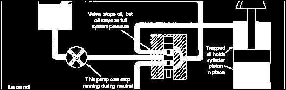
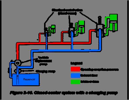
26 Path-offlow type Control type Position type Spring type Spool type Classification Two way Four way Manual operated Pilot operated Solenoid operated Solenoid controlled, pilot operated Two position Three position Spring offset No spring Spring centered Open center Closed center Tandem center Partially closed center Semi-open center Description Allows a total of two possible flow paths in two extreme spool positions Allows a total of four possible flow paths in two extreme spool positions Hand lever is used to shift the spool. Hydraulic pressure is used to shift the spool. Solenoid action is used to shift the spool. Solenoid action is used to shift the integral pilot spool, which directs the pilot flow to shift the main spool. Spool has two extreme positions of dwell. Spool has two extreme positions plus one intermediate or center position. Spring action automatically returns the spool to the normal offset position as soon as shifter force is released. (Spring offset is always a two-way valve.) Spool is not spring-loaded; it is moved only by shifter force, and it remains where it is shifted (may be twoor three-position type, but three-position type uses detent). Spring action automatically returns the spool to the center position as soon as the shifter force is released. (Spring-centered is always a three-position valve.) These are five of the more common spool types. They refer to the flow pattern allowed when the spool is in the center position (three-position valves) or in the cross-over position (two-position valves). In a closed-center spool valve, a piston is solid, and all passages through a valve are blocked when a piston is centered in its cylinder. A closed-center valve is used when a single pump or an accumulator performs more than one operation and where there must be no pressure loss in shifting a stroke direction at a work point. In an open-center spool valve, the spools on a piston are slotted or channeled so that all passages are open to each other when a piston is centered. In some open-center valves, passages to a cylinder port are blocked when a valve is centered and liquid from a pump is carried through a piston and out the other side of a valve to a reservoir. Liquid must be carried to both ends of a piston of a directional valve to keep it balanced. Instead of discharging into a reservoir when a valve is centered, liquid may be directed to other valves so that a set of operations is performed in sequence.


27 Open-center valves are used when a work cylinder does not have to be held in position by pressure and where power is used to perform a single operation. These valves also avoid shock to a system when a valve spool is moved from one position to another, since in the intermediate position, pressure is temporarily relieved by liquid passing from a pump directly to the reservoir. Basic Hydraulic Circuit Illustrations


28
Describe the function of a hydraulic power unit
 Chapter 7 Source of Hydraulic Power Power Units and Pumps 1 Objectives Describe the function of a hydraulic power unit and identify its primary components. Explain the purpose of a pump in a hydraulic
Test Which component has the highest Energy Density? A. Accumulator. B. Battery. C. Capacitor. D. Spring.
 Test 1 1. Which statement is True? A. Pneumatic systems are more suitable than hydraulic systems to drive powerful machines. B. Mechanical systems transfer energy for longer distances than hydraulic systems.
CH.4 Basic Components of Hydraulic and Pneumatic System/16 M HAP/17522/AE5G
 Content : 4.1 Hydraulic and Pneumatic actuators. 10 Marks Hydraulic Actuators - Hydraulic cylinders (single, double acting and telescopic) construction and working, Hydraulic motors (gear and piston type)
Hydraulic Pumps Classification of Pumps
 Fluidsys Training Centre, Bangalore offers an extensive range of skill-based and industry-relevant courses in the field of Pneumatics and Hydraulics. For more details, please visit the website: https://fluidsys.org
Topic 1. Basics of Oil Hydraulic Systems
 Topic 1. Basics of Oil Hydraulic Systems Fluid power Fluid power is the technology that deals with the generation, control and transmission of forces and movement of mechanical element or system with the
2. Hydraulic Valves, Actuators and Accessories. 24 Marks
 2. Hydraulic Valves, Actuators and Accessories 24 Marks Co related to chapter 602.2 Describe working principle of various components used in hydraulic & pneumatic systems. 602.3 Choose valves, actuators
Marine Engineering Exam Resource Review of Hydraulics
 1. What is Pascal s law? Pressure confined on a confined fluid will transmit the pressure in all directions and act with equal force on all areas at right angles. 2. How does the law pertain to hydraulics?
A pump is a machine used to move liquid through a piping system and to raise the pressure of the liquid.
 What is a pump A pump is a machine used to move liquid through a piping system and to raise the pressure of the liquid. Why increase a liquid s pressure? Static elevation a liquid s pressure must be increased
Lesson 5: Directional Control Valves
 : Directional Control Valves Basic Hydraulic Systems Hydraulic Fluids Hydraulic Tank Hydraulic Pumps and Motors Pressure Control Valves Directional Control Valves Flow Control Valves Cylinders : Directional
Definitions of Technical Terms
 Definitions of Technical Terms ABSOLUTE A measure having as it s zero point of base the complete absence of the entity being measured. ABSOLUTE PRESSURE A pressure scale with zero point at a perfect vacuum.
Module 5: Valves. CDX Diesel Hydraulics. Terms and Definitions. Categories of Valves. Types of Pressure Control Valves
 Terms and Definitions Categories of Valves Types of Pressure Control Valves Types and Operation of Pressure Relief Valves Operation of an Unloading Valve Operation of a Sequencing Valve Operation of a
CLOSED CIRCUIT HYDROSTATIC TRANSMISSION
 Energy conservation and other advantages in Mobile Equipment Through CLOSED CIRCUIT HYDROSTATIC TRANSMISSION C. Ramakantha Murthy Technical Consultant Various features/advantages of HST Hydrostatic transmissions
Section 6.1. Implement Circuit - General System. General: TF Configuration TB Configurations Implement Control Valve:
 Section 6.1 Implement Circuit - General System General: TF Configuration... 6.1.3 TB Configurations... 6.1.5 Implement Pump Breakdown... 6.1.6 Operational Description: General... 6.1.7 Compensator Control...
INTRODUCTION: Rotary pumps are positive displacement pumps. The rate of flow (discharge) of rotary pump remains constant irrespective of the
 of rotary pump remains constant irrespective of the") INTRODUCTION: Rotary pumps are positive displacement pumps. The rate of flow (discharge) of rotary pump remains constant irrespective of the pressure. That is, even at very high pressure, these pumps can
INTRODUCTION: Rotary pumps are positive displacement pumps. The rate of flow (discharge) of rotary pump remains constant irrespective of the pressure. That is, even at very high pressure, these pumps can
VB VALVES & AUTOMATION
 Introduction to Valve What are Valves? Valves are mechanical device that controls the flow and pressure within a system or process. They are essential components of a piping system that conveys liquids,
speed hydraulic motors. Permission granted to reproduce for educational use only. Contrast the operation of fixed- and variable-
 Chapter 9 Actuators Workhorses of the System 1 Objectives Describe the construction and operation of basic hydraulic cylinders, limited-rotation actuators, and motors. Compare the design and operation
Lecture 6. Systems review exercise To be posted this weekend Due next Friday (3/6)
") 150 Systems review exercise To be posted this weekend Due next Friday (3/6) Lecture 6 Coming week: Lab 13: Hydraulic Power Steering Lab 14: Integrated Lab (Hydraulic test bench) Topics today: Pumps and
150 Systems review exercise To be posted this weekend Due next Friday (3/6) Lecture 6 Coming week: Lab 13: Hydraulic Power Steering Lab 14: Integrated Lab (Hydraulic test bench) Topics today: Pumps and
INDIAN INSTITUTE OF TECHNOLOGY KHARAGPUR NPTEL ONLINE CERTIFICATION COURSE. On Industrial Automation and Control
 INDIAN INSTITUTE OF TECHNOLOGY KHARAGPUR NPTEL ONLINE CERTIFICATION COURSE On Industrial Automation and Control By Prof. S. Mukhopadhyay Department of Electrical Engineering IIT Kharagpur Topic Lecture
Nomenclature... xi Hydraulic Laws, Theorems, and Equations...xii
 Nomenclature... xi Hydraulic Laws, Theorems, and Equations...xii 1 Introduction 1.1 Component Design Perspective...1 1.2 Hydraulic Power Evolution...2 1.3 Hydraulic Applications...6 1.4 Component Design
ESCONDIDO FIRE DEPT TRAINING MANUAL Section DRIVER OPERATOR Page 1 of 13 Pumps and Accessory Equipment Revised
 DRIVER OPERATOR Page 1 of 13 PUMPS AND ACCESSORY EQUIPMENT Pumps are designed for many different purposes. In order to understand the proper application and operation of a pump in a given situation, firefighters
Input, Control and Processing elements
 PNEUMATIC & HYDRAULIC SYSTEMS CHAPTER FIVE Input, Control and Processing elements Dr. Ibrahim Naimi Valves The function of valves is to control the fluid path or the pressure or the flow rate. Depending
FLUID POWER TUTORIAL HYDRAULIC PUMPS APPLIED PNEUMATICS AND HYDRAULICS H1
 FLUID POWER TUTORIAL HYDRAULIC PUMPS This work covers outcome 2 of the Edexcel standard module: APPLIED PNEUMATICS AND HYDRAULICS H1 The material needed for outcome 2 is very extensive so the tutorial
three different ways, so it is important to be aware of how flow is to be specified
 Flow-control valves Flow-control valves include simple s to sophisticated closed-loop electrohydraulic valves that automatically adjust to variations in pressure and temperature. The purpose of flow control
LogSplitterPlans.Com
 Hydraulic Pump Basics LogSplitterPlans.Com Hydraulic Pump Purpose : Provide the Flow needed to transmit power from a prime mover to a hydraulic actuator. Hydraulic Pump Basics Types of Hydraulic Pumps
Chapter 6. Supercharging
 SHROFF S. R. ROTARY INSTITUTE OF CHEMICAL TECHNOLOGY (SRICT) DEPARTMENT OF MECHANICAL ENGINEERING. Chapter 6. Supercharging Subject: Internal Combustion Engine 1 Outline Chapter 6. Supercharging 6.1 Need
VALVE TIMING DIAGRAM FOR SI ENGINE VALVE TIMING DIAGRAM FOR CI ENGINE
 VALVE TIMING DIAGRAM FOR SI ENGINE VALVE TIMING DIAGRAM FOR CI ENGINE Page 1 of 13 EFFECT OF VALVE TIMING DIAGRAM ON VOLUMETRIC EFFICIENCY: Qu. 1:Why Inlet valve is closed after the Bottom Dead Centre
Water Treatment Plant Maintenance Considerations. Operation and Maintenance. Types of Maintenance 5/1/15
 Water Treatment Plant Maintenance 1 Operation and Maintenance Purpose of O&M maintain design functionality (capacity) restore the system components to their original condition and thus functionality. Effective
HYDRAULIC VARIABLE PUMPS
 HYDRAULIC VARIABLE S EFFICIENT VARIABLE DELIVERY Checkball pump delivery is controlled by variable inlet ports in each piston pumping chamber. In these hydraulic variable models, output is regulated by
TPV Variable Displacement Closed Loop System Axial Piston Pump THE PRODUCTION LINE OF HANSA-TMP HT 16 / M / 852 / 0815 / E
 HYDRAULIC COMPONENTS HYDROSTATIC TRANSMISSIONS GEARBOXES - ACCESSORIES Certified Company ISO 9001-14001 ISO 9001 Via M. L. King, 6-41122 MODENA (ITALY) Tel: +39 059 415 711 Fax: +39 059 415 729 / 059 415
The Cement Industry. How can Kinetrol help your business? Cement Manufacturing Process. Pneumatic Vehicle Unloading. Silo Discharge.
 The Cement Industry How can Kinetrol help your business? In today's working environment, especially in the Cement Industry, it is essential that all economic and safety issues are addressed. Poor quality
Chapter 2. The Vehicle-Tank Metering System
 Chapter 2 The Vehicle-Tank Metering System Chapter Objectives Upon completion of this chapter, you should be able to: 1. Describe the vehicle-tank metering system, its uses, and its relation to other liquid-volume
INTERNAL COMBUSTION ENGINE (SKMM 4413)
") INTERNAL COMBUSTION ENGINE (SKMM 4413) Dr. Mohd Farid bin Muhamad Said Room : Block P21, Level 1, Automotive Development Centre (ADC) Tel : 07-5535449 Email: mfarid@fkm.utm.my HISTORY OF ICE History of
INTERNAL COMBUSTION ENGINE (SKMM 4413) Dr. Mohd Farid bin Muhamad Said Room : Block P21, Level 1, Automotive Development Centre (ADC) Tel : 07-5535449 Email: mfarid@fkm.utm.my HISTORY OF ICE History of
AN EXPLANATION OF CIRCUITS CARTER YH HORIZONTAL CLIMATIC CONTROL CARBURETER
 AN EXPLANATION OF CIRCUITS CARTER YH HORIZONTAL CLIMATIC CONTROL CARBURETER The Carter Model YH carbureter may be compared with a Carter YF downdraft carbureter with the circuits rearranged to operate
What is Wear? Abrasive wear
 What is Wear? Written by: Steffen D. Nyman, Education Coordinator, C.C.JENSEN A/S It is generally recognized that contamination of lubricating and hydraulic oils are the primary cause of wear and component
To ensure proper installation, digital pictures with contact information to before startup.
 Check List for Optimal Filter Performance? There should be no back-pressure on the flush line. A 1 valve should have a 2 waste line, and 2 valve should have a 3 waste line. Do not use rubber hosing or
NECO Pumping Systems
 INSTALLATION OPERATION & MAINTENANCE INSTRUCTIONS For Your NECO Pumping Systems Fuel Oil Transfer System THIS COMPLETELY ASSEMBLED, TESTED, PACKAGED SYSTEM IS OF THE HIGHEST QUALITY AND DESIGN. TO OBTAIN
LACT MEASUREMENT. Total Head = Or PSI = S.G. 2.31
 LACT MEASUREMENT Prepared By: Ken A. Steward. P.E. Linco-Electromatic, Inc. 4580 West Wall Street Midland, Texas 79703 The Operation of L.A.C.T. Units The simplest approach to the understanding of the
EXPANSION JOINT SELECTION GUIDE
 EXPANSION JOINT SELECTION GUIDE The proper selection and application of an expansion joint is the determining factor in its operation and life. Improper selection and application will lead to problems
TPV Variable Displacement Closed Loop System Axial Piston Pump THE PRODUCTION LINE OF HANSA-TMP HT 16 / M / 851 / 0813 / E
 HYDRAULIC COMPONENTS HYDROSTATIC TRANSMISSIONS GEARBOXES - ACCESSORIES THE PRODUCTION LINE OF HANSA-TMP Variable Displacement Closed Loop System CONTENTS General Information... Order Code... Manual Control
TECHNICAL PAPER 1002 FT. WORTH, TEXAS REPORT X ORDER
 I. REFERENCE: 1 30 [1] Snow Engineering Co. Drawing 80504 Sheet 21, Hydraulic Schematic [2] Snow Engineering Co. Drawing 60445, Sheet 21 Control Logic Flow Chart [3] Snow Engineering Co. Drawing 80577,
Driver Driven. InputSpeed. Gears
 Gears Gears are toothed wheels designed to transmit rotary motion and power from one part of a mechanism to another. They are fitted to shafts with special devices called keys (or splines) that ensure
Lecture 6. Systems review exercise To be posted this afternoon Due in class (10/23/15)
") 153 Systems review exercise To be posted this afternoon Due in class (10/23/15) Lecture 6 Coming week: Lab 13: Hydraulic Power Steering Lab 14: Integrated Lab (Hydraulic test bench) Topics today: 2 min
153 Systems review exercise To be posted this afternoon Due in class (10/23/15) Lecture 6 Coming week: Lab 13: Hydraulic Power Steering Lab 14: Integrated Lab (Hydraulic test bench) Topics today: 2 min
RV1P /118 ED VARIABLE DISPLACEMENT VANE PUMPS SERIES 10 OPERATING PRINCIPLE TECHNICAL SPECIFICATIONS HYDRAULIC SYMBOL
 14 201/118 ED RV1P VARIABLE DISPLACEMENT VANE PUMPS OPERATING PRINCIPLE TECHNICAL SPECIFICATIONS (measured with mineral oil with viscosity of 46 cst at 40 C) RV1P are variable displacement vane pumps with
RELEASING PRESSURE IN THE HYDRAULIC SYSTEM,
 Testing And Adjusting Introduction NOTE: For Specifications with illustrations, make reference to SPECIFICATIONS for 225 EXCAVATOR HYDRAULIC SYSTEM, Form No. SENR7734. If the Specifications are not the
Job Sheet 1 Introduction to Fluid Power
 Job Sheet 1 Introduction to Fluid Power Fluid Power Basics Fluid power relies on a hydraulic system to transfer energy from a prime mover, or input power source, to an actuator, or output device (Figure
LECTURE 30 to 31 ACCESSORIES USED IN FLUID POWER SYSTEMS FREQUENTLY ASKED QUESTIONS
 LECTURE 30 to 31 ACCESSORIES USED IN FLUID POWER SYSTEMS FREQUENTLY ASKED QUESTIONS 1. Explain the two types of the leakages in hydraulic system. In what way do they affect the performance of a fluid system?
Module 4: Actuators. CDX Diesel Hydraulics. Terms and Definitions. Cylinder Actuators
 Terms and Definitions Cylinder Actuators Symbols for Actuators Terms and Definitions II Cylinders Providing Linear Motion Cylinders Providing Angular Motion Parts of Actuators Mounting of Actuators Seals
CONCEPTUAL DESIGN OF A NEW TYPE OF ENGINE FOR VARIOUS APPLICATIONS WITH EXPECTED 10% HIGHER OVERALL EFFICIENCY
 International Journal of Mechanical and Production Engineering Research and Development (IJMPERD ) Vol.1, Issue 2 Dec 2011 58-65 TJPRC Pvt. Ltd., CONCEPTUAL DESIGN OF A NEW TYPE OF ENGINE FOR VARIOUS APPLICATIONS
DESIGN CONSIDERATIONS FOR ROTATING UNIONS SEALING TECHNOLOGIES
 DESIGN CONSIDERATIONS FOR ROTATING UNIONS SEALING TECHNOLOGIES Rotating unions convey fluid from a stationary supply line to equipment or a rotating tool. They are critical elements in a variety of applications
Glossary. Visit Us Online: ABSOLUTE A measure having as its zero point or base the complete absence of the entity being measured.
 ABSOLUTE A measure having as its zero point or base the complete absence of the entity being measured. ABSOLUTE PRESSURE (psia) The pressure above absolute zero, the sum of atmospheric and gauge pressure.
Technical Information for PVX Series Pumps
 Technical Information for PVX Series Pumps TM 604 PROGRESS DRIVE, HARTLAND, WI 53029 USA Phone: (262) 367-4299 FAX: (262) 367-5645 URL: www.hartmanncontrols.com E-mail: sales@hartmanncontrols.com PVX pumps
AGN 076 Alternator Bearings
 Application Guidance Notes: Technical Information from Cummins Generator Technologies AGN 076 Alternator Bearings BEARING TYPES In the design of STAMFORD and AvK alternators, the expected types of rotor
FLUID POWER FLUID POWER EQUIPMENT TUTORIAL HYDRAULIC AND PNEUMATIC MOTORS. This work covers part of outcome 2 of the Edexcel standard module:
 FLUID POWER FLUID POWER EQUIPMENT TUTORIAL HYDRAULIC AND PNEUMATIC MOTORS This work covers part of outcome 2 of the Edexcel standard module: UNIT 21746P APPLIED PNEUMATICS AND HYDRAULICS The material needed
Section 6.1. Implement Circuit - General System. General: Implement Control Valve:
 Section 6.1 Implement Circuit - General System General: Implement Circuit... 6.1.3 Implement Pump Breakdown... 6.1.4 Operational Description: General... 6.1.5 Compensator Control... 6.1.6 Standby Condition...
HE Stewart Vacuum Gasoline System employs a small tank, installed under the hood. This tank is connected by brass tubing to the intake manifold, also
 T HE Stewart Vacuum Gasoline System employs a small tank, installed under the hood. This tank is connected by brass tubing to the intake manifold, also to gasoline supply tank, and to carburetor. Every
Design and Fabrication of Sequencing Circuit with Single Double Acting Cylinder
 Design and Fabrication of Sequencing Circuit with Single Double Acting Cylinder V.G.Vijaya Department of Mechatronics Engineering, Bharath University, Chennai 600073, India ABSTRACT: This project deals
#9040 FUEL TANK SWEEPER
 #9040 FUEL TANK SWEEPER INSTRUCTION MANUAL FILTERS AND REMOVES FINE BIO-CONTAMINANTS, ALGAE, ETC. SWEEPING PROCESS REMOVES LARGE CONTAMINANTS FROM OIL TANKS SUCH AS RUST, WATER, CRUDE AND DIRT CIRCULATES
Turbine, Generator & Auxiliaries - Course 234
 Turbine, Generator & Auxiliaries - Course 234 STEAM VALVE HYDRAULIC CONTROL The movement of large control valves to regulate the steam supply to modern steam turbines, requires amplification of the control
Name Date. True-False. Multiple Choice
 Name Date True-False T F 1. Oil film thickness increases with an increase in oil temperature. T F 2. Displacement is the volume that a piston displaces in an engine when it travels from top dead center
LECTURE-23: Basic concept of Hydro-Static Transmission (HST) Systems
 Systems") MODULE-6 : HYDROSTATIC TRANSMISSION SYSTEMS LECTURE-23: Basic concept of Hydro-Static Transmission (HST) Systems 1. INTRODUCTION The need for large power transmissions in tight space and their control
MODULE-6 : HYDROSTATIC TRANSMISSION SYSTEMS LECTURE-23: Basic concept of Hydro-Static Transmission (HST) Systems 1. INTRODUCTION The need for large power transmissions in tight space and their control
PCP Series Piston Pumps - Industrial
 Compensated, Variable Volume Features Variable Volume, Compensated Design: Reduces heat, noise and horsepower requirements. ump maintains constant pressure while matching system flow demands. Super Quiet
Section 6.1. Implement Circuit - General System. General: TF Configuration TB Configurations Implement Control Valve:
 Section 6.1 Implement Circuit - General System General: TF Configuration... 6.1.3 TB Configurations... 6.1.5 Implement Pump Breakdown... 6.1.6 Operational Description: General... 6.1.7 Compensator Control...
Penn Valley Pump Company Design Information for Double Disc Pumps
 Penn Valley Pump Company Design Information for Double Disc Pumps INTRODUCTION The Penn Valley Double Disc Pump utilizes a unique principle of operation whereby the discs perform the duties of pumping
Hydraulic Power Supply and Motors Concept and Theory
 Hydraulic Power Supply and Motors Concept and Theory Graco, Inc. P.O. Box 1441 Minneapolis, MN 55440-1441 1996 Graco Inc. Form No. 321-046 1/96 Rev 2 SL Training 11/14 Hydraulic Systems Component Identification
Check Valves Check Valves are the simplest form of directional control valves, but they can also be used as pressure controls.
 Check Valves Check Valves are the simplest form of directional control valves, but they can also be used as pressure controls. Standard Check Valve The standard check valve permits free flow in one direction
Section 6.1. Implement Circuit - General System. General: Implement Control Valve: Implement Circuit
 Section 6.1 Implement Circuit - General System General: Implement Circuit... 6.1.3 Implement Pump Breakdown... 6.1.4 Operational Description: General... 6.1.5 Compensator Control... 6.1.6 Standby Condition...
I) Clamping the work piece II) Drilling the work piece. III) Unclamping the work piece. 10
 Clamping the work piece II) Drilling the work piece. III) Unclamping the work piece. 10") Seventh Semester B.E. III IA Test, 2014 USN 1 P E M E PES INSTITUTE OF TECHNOLOGY (Bangalore South Campus) (Hosur Road, 1KM before Electronic City, Bangalore-560 100) Department of Mechanical Engineering
Seventh Semester B.E. III IA Test, 2014 USN 1 P E M E PES INSTITUTE OF TECHNOLOGY (Bangalore South Campus) (Hosur Road, 1KM before Electronic City, Bangalore-560 100) Department of Mechanical Engineering
ISO Certificate N 12-E TIC. ISO 9001 Certificate N 12-Q TIC
 HYDRAULIC COMPONENTS HYDROSTATIC TRANSMISSIONS GEARBOXES - ACCESSORIES Certified Company ISO 9001-14001 ISO 9001 Certificate N 12-Q-0200545-TIC ISO 14001 Certificate N 12-E-0200545-TIC Via M. L. King,
NECO Pumping Systems
 INSTALLATION OPERATION & MAINTENANCE INSTRUCTIONS For Your NECO Pumping Systems PACKAGED CIRCULATING SYSTEM THIS COMPLETELY ASSEMBLED, TESTED, PACKAGED CIRCULATING SYSTEM IS OF THE HIGHEST QUALITY AND
Internal combustion engines can be classified in a number of different ways: 1. Types of Ignition
 Chapter 1 Introduction 1-3 ENGINE CLASSIFICATIONS Internal combustion engines can be classified in a number of different ways: 1. Types of Ignition 1 (a) Spark Ignition (SI). An SI engine starts the combustion
Table 6-1. Problems and solutions with pump operations. No Fluid Delivery
 Table 6-1. and solutions with pump operations No Fluid Delivery Fluid level in the reservoir is low. Oil intake pipe or inlet filter is plugged. Air leak in the inlet line prevents priming or causes noise
CHAPTER 11 BASIC ACTUATING SYSTEMS
 INTRODUCTION CHAPTER 11 BASIC ACTUATING SYSTEMS The actuating systems consist of the hydraulic components used to direct and control the flow of pressurized fluid as well as the components used to perform
FRL unit consist of Filterations, Regulators and Lubricator unit.
 4.1 AIR CONTROL 4.1.1 Fluid Conditioner FRL unit consist of Filterations, Regulators and Lubricator unit. It is also known as Air Service Unit. Primary function is to provide clean air at optimal pressure
SAMPLE STUDY MATERIAL
 IC Engine - ME GATE, IES, PSU 1 SAMPLE STUDY MATERIAL Mechanical Engineering ME Postal Correspondence Course Internal Combustion Engine GATE, IES & PSUs IC Engine - ME GATE, IES, PSU 2 C O N T E N T 1.
Instructor Training Manual. Chapter 6 HYDRAULICS & PNEUMATICS
 Instructor Training Manual Chapter 6 HYDRAULICS & PNEUMATICS Learning Objectives 1. The purpose of this chapter is to provide a basic introduction to the principles of hydraulics & pneumatics and their
TROUBLESHOOTING TABLE
 TROUBLESHOOTING TABLE TROUBLESHOOTING GUIDE GLOSARY OF TERMS VANE PUMPS NO FLOW, NO PRESSURE A) Is the pump rotating? a-1) Check if the coupling is rotating. If not, check the rotation of the electric
2. Power Steering System
 2. Power Steering System A: HYDRAULIC SYSTEM POWER STEERING SYSTEM The fluid pump is directly driven by the engine through a belt. The fluid flow is maintained almost constant regardless of change in the
Internal Combustion Engines
 Internal Combustion Engines The internal combustion engine is an engine in which the burning of a fuel occurs in a confined space called a combustion chamber. This exothermic reaction of a fuel with an
FIXED DISPLACEMENT HYDRAULIC VANE PUMPS SERIE BQ
 FIXED DISPLACEMENT HYDRAULIC VANE PUMPS SERIE BQ BQ FIXED DISPLACEMENT HYDRAULIC VANE PUMPS BQ SERIES Versatility, power, compactness and low running costs are the main characteristics of B&C vane pumps.
DESIGN, OPERATION & MAINTENANCE OF L.A.C.T. UNITS
 DESIGN, OPERATION & MAINTENANCE OF L.A.C.T. UNITS INTRODUCTION The two most common methods of measuring the volume of petroleum liquids are tank gauging and liquid metering. The problems associated with
Operating instructions Form no safety definitions
 Operating instructions Form no. 1000437 safety definitions safety symbols are used to identify any action or lack of action that can cause personal injury. Your reading and understanding of these safety
In order to discuss powerplants in any depth, it is essential to understand the concepts of POWER and TORQUE.
 -Power and Torque - ESSENTIAL CONCEPTS: Torque is measured; Power is calculated In order to discuss powerplants in any depth, it is essential to understand the concepts of POWER and TORQUE. HOWEVER, in
(Refer Slide Time: 1:13)
") Fluid Dynamics And Turbo Machines. Professor Dr Dhiman Chatterjee. Department Of Mechanical Engineering. Indian Institute Of Technology Madras. Part A. Module-2. Lecture-2. Turbomachines: Definition and
Fluid Dynamics And Turbo Machines. Professor Dr Dhiman Chatterjee. Department Of Mechanical Engineering. Indian Institute Of Technology Madras. Part A. Module-2. Lecture-2. Turbomachines: Definition and
FIXED DISPLACEMENT HYDRAULIC VANE PUMPS SERIE BQ
 FIXED DISPLACEMENT HYDRAULIC VANE PUMPS SERIE BQ BQ FIXED DISPLACEMENT HYDRAULIC VANE PUMPS BQ SERIES Versatility, power, compactness and low running costs are the main characteristics of B&C vane pumps.
SHAFT ALIGNMENT FORWARD
 Service Application Manual SAM Chapter 630-76 Section 24 SHAFT ALIGNMENT FORWARD One of the basic problems of any installation is aligning couplings or shafts. Therefore, this section will endeavor to
Chapter B-3. Chapter 3. Actuators and output devices. Festo Didactic TP101
 155 Chapter 3 Actuators and output devices Festo Didactic TP101 156 An actuator is an output device for the conversion of supply energy into useful work. The output signal is controlled by the control
Troubleshooting the Transmission Hydraulic System
 Testing and Adjusting IT28F INTEGRATED TOOLCARRIER POWER TRAIN Testing And Adjusting Introduction Reference: For Specifications with illustrations, refer to SENR5974, IT28F Integrated Toolcarrier Power
Section 35 Chapter 2 HYDRAULIC SYSTEM HOW IT WORKS AND TROUBLESHOOTING NH
 Section 35 Chapter HYDRAULIC SYSTEM HOW IT WORKS AND TROUBLESHOOTING 6-80NH TABLE OF CONTENTS GENERAL INTRODUCTION... 35-3 Hydraulic Pumps... 35-3 Standard Flow PFC Pump Layout... 35-5 MegaFlow PFC Pump
TABLE 1: COMPARISON OF GREASE AND OIL LUBRICATION. housing structure and sealing method. speed. cooling effect. removal of foreign matter
 TECHNICAL INSIGHT PRODUCT AND APPLICATION ENGINEERING INFORMATION A PUBLICATION OF NSK AMERICAS LUBRICATION - OPTIMIZING BEARING LIFE Lubrication is a critical component to extending bearing life. Without
CHAPTER 6 GEARS CHAPTER LEARNING OBJECTIVES
 CHAPTER 6 GEARS CHAPTER LEARNING OBJECTIVES Upon completion of this chapter, you should be able to do the following: Compare the types of gears and their advantages. Did you ever take a clock apart to
Denison GOLD CUP Product Catalog Piston Pumps & Motors For Open & Closed Circuits
 aerospace climate control electromechanical filtration fluid & gas handling hydraulics pneumatics process control sealing & shielding Denison GOLD CUP Product Catalog Piston Pumps & Motors For Open & Closed
Hydraulic Maintenance & Troubleshooting. Content - Norman Kronowitz Presenter Jim Trinkle
 Hydraulic Maintenance & Troubleshooting Content - Norman Kronowitz Presenter Jim Trinkle Introduction Welcome to the CMA/Flodyne/Hydradyne s Hydraulic Troubleshooting presentation. We will introduce many
Pneumatic High-Viscosity Filtration System Instruction Manual
 Pneumatic High-Viscosity Filtration System Instruction Manual P/N: 61512 05/17 1 2 Pneumatic High Viscosity Filtration Systems PN: 61512 14 April, 2009 rev A 36933 Pneumatic Hand Cart HV Filtration System
VIS (Valve-In-Star) Hydraulic Motor
 Hydraulic Motor") VIS (Valve-In-Star) Hydraulic Motor VIS 30 Series VIS 40 Series VIS 45 Series The next step in the evolution of low speed high torque (LSHT) hydraulic motors. EATON Low Speed High Torque Motors E-MOLO-MC001-E5
VIS (Valve-In-Star) Hydraulic Motor VIS 30 Series VIS 40 Series VIS 45 Series The next step in the evolution of low speed high torque (LSHT) hydraulic motors. EATON Low Speed High Torque Motors E-MOLO-MC001-E5
Best Practice Variable Speed Pump Systems
 Best Practice Variable Speed Pump Systems Contents 1 Introduction 3 General Recommendations 4 2 Pumping Systems 6 3 Effects of Speed Variation 8 4 Variable Speed Drives 9 5 Financial Savings 11 Introduction
Fixed Displacement Gear Pumps
 Fixed Displacement Gear Pumps D/H/HD Series Introduction Series D/H/HD Features Pressure-loaded design Efficient, simple design - few moving parts Exceptionally compact and lightweight for their capacity
ENGINE & WORKING PRINCIPLES
 ENGINE & WORKING PRINCIPLES A heat engine is a machine, which converts heat energy into mechanical energy. The combustion of fuel such as coal, petrol, diesel generates heat. This heat is supplied to a
FUNDAMENTAL PRINCIPLES
 FUNDAMENTAL PRINCIPLES Fundamental Principles The most important safety feature of an automobile is its brake system. The ability of a braking system to provide safe, repeatable stopping is the key to
APCO SLANTING DISC CHECK VALVES
 BULLETIN 800 JULY 2011 APCO SLANTING DISC CHECK VALVES Series 800, 800B, 800T APCO Slanting Disc Check Valve With decades of experience to guarantee reliability and outstanding performance, our Slanting
Industrial Mechanic (Millwright) Level 3
 Level 3") Industrial Mechanic (Millwright) Level 3 Rev. September 2005 Industrial Mechanic (Millwright) Unit: G5 Prime Movers I Diesel 1 Level: Duration: Three 60 hours Theory: 20 hours Practical: 40 hours Overview:
Industrial Mechanic (Millwright) Level 3 Rev. September 2005 Industrial Mechanic (Millwright) Unit: G5 Prime Movers I Diesel 1 Level: Duration: Three 60 hours Theory: 20 hours Practical: 40 hours Overview: