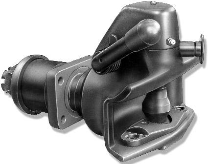
RINGFEDER. Automatic Trailer Couplings for connecting to 40 mm drawbar eyes according to DIN Type 604/ 605/ 6041/ 6051/ 6061.
|
|
|
- Briana Reynolds
- 5 years ago
- Views:
Transcription

1 RINGFEDER DE Prospekt Prospect Automatic Trailer Couplings for connecting to 40 mm drawbar eyes according to DIN Type 604/ 605/ 6041/ 6051/ 6061 Type 6051
2 Automatic Trailer Couplings Type 604, Type 605, Type 6041, Type 6051, Type 6061 for 40 mm drawbar eyes according to DIN (41) , 4, 6 only applicable to types 604, 605 7


3 Parts List for replacement and maintenance Item Order No. Description Type safety catch assembly, cpl. 604, 605, 6041,6051, guide bush 604, guide bush 6041, 6051, plastic wearing plate, cpl. 604, a handle 604, 605, 6041, 6051, b handle, right 604, locking lever 604, 605, 6041,6051, coupling pin, cpl. 604, 605, 6041,6051, a return spring, left 604, 605, 6041,6051, b return spring, right 604, cover, complete 604, cover, complete 6041, 6051, hexagonal screw M 8 x 65, cpl. 604, 605, 6041,6051, rubber spring (2 pcs.) rubber spring (2 pcs.) rubber spring (2 pcs.) 6041,6051, thrust washer thrust washer thrust washer 6041, bar guide, complete bar guide, complete 605 Item Order No. Description Type bar guide, complete bar guide, complete bar guide, complete 6061 a (on request) bearing bush (2 pcs.) bearing bush (2 pcs.) bearing bush (2 pcs.) 6041, 6051, (cupped) tension washer tension washer tension washer 6041, 6051, spring washer B 30, DIN spring washer B 36, DIN spring washer B 45, DIN , 6051, castellated nut M 30, complete castellated nut M 36 x 3, complete castellated nut M 45 x 3, complete 6041, 6051, cotter pin 6.3 x 50, DIN 94, St, A3C cotter pin 6.3 x 63, DIN 94, St, A3C cotter pin 8 x 80, DIN 94, St, A3C 6041, 6051, protecting cap protecting cap 6041, 6051, 6061 Installation Instructions Fitting: Remove castellated nut (42). Pull off spring washer (41), tension washer (40), rubber spring (36) and bar guide (38) (including the support plate (47)) from the drawbar (1). Caution: The support plate (47) is not included in all coupling types. The assembly sequence for coupling types without support plate is the same, except the support plate does not apply. Remove support plate (47) from the bar guide (38). Fit bar guide (38) contrary to the driving direction to the inner face of the rear cross member. Fit support plate (47) in driving direction to the outer face of the cross member and onto the bar guide shank. Tighten the bar guide (38) (including support plate) together with the cross member using 4 fastening bolts quality 8.8 and 4 hexagonal nuts quality 8. On the cross member washers DIN 125, hardness HV have to be added. Fit coupling head assembly including the front rubber Bolt length: bolt shank + washer thickness + nut length + at least 2 threads projection spring (36) and thrust washer (37) to the bar guide (38). If required, regrease drawbar (1). Fit the rear rubber spring (36), tension washer (40) and spring washer (41). Screw on and tighten the castellated nut (42) and secure using a cotter pin. To reach the next hole position for the cotter pin even higher tightening torques may be required. Min. Tightening Torques Fit protective plastic cap (44). Straighten the coupling. For a retro-fit please refer to the relevant statutory regulations. Fitting of this coupling may only be effected on those vehicles which due to their construction prevent the trailer from running up in case the drawbar eye misses the coupling mouth, and the rear end design of which does not allow a horizontal articulation of the trailer tow bar exceeding 80. On this assumption the trailer coupling types are approved for: a) motor vehicles according to DIN 74051, footnote 3, e.g. motor vehicles type UNIMOG from Daimler Benz AG, b) towing vehicles according to StVZO 43, paragraph 4, fig. 2, c) multiple axle trailers. Operation: Wrench Size M Nm = 46 mm M 36 x Nm = 55 mm M 45 x Nm = 70 mm Pull out and hold the button-type safety device (4), move handle (15) upwards until the coupling bolt locks into place. Insert the towing eye. While the coupling bolt (23) is being lifted the catch is released and the coupling bolt slides into position. Simultaneously the button-type safety device (4) is released that is to say the safety bar locates over the coupling bolt and thus locking it automatically. The towing eye is now engaged. Check that after each coupling process the button-type safety device (4) is fully engaged so that the securing knob is in its internal engaged position. If this is not the case the trailer coupling is unsecured and the whole coupling procedure must be repeated. To uncouple and open the trailer coupling proceed as described. The towing eye is extended by moving forward the towing vehicle. Due to the extension of the towing eye the coupling mechanism is again released and thus the coupling repeatedly closed and secured. Maintenance: The coupling bolt and towing eye will be subject to less wear and tear if they are always kept clean and well lubricated. Should the wear limit of 36.5 mm of the coupling bolt in the bulged area (outside diameter) be reached the coupling bolt has to be replaced by a new one. Fig. 1 The handle can be fitted on the right or left-hand side if only the return spring is chosen correspondingly (please refer to fig. 1 and fig. 2). e 1 x e 2 d 2 Thread Torque Moment Wrench Type (mm) (mm) (Standard Thread) Size (mm) 83 x 56 ø 10,5 M Nm 17(16) x 55 ø15 M Nm x 80 ø17 M Nm x 100 ø21 M Nm Fig. 2


4 Type 604 Type 605 Type 6041/ Type 6051 Type 6061


5 Technical drawing: Type 605 Flange Design d 2 e 2 g l 3 l 2 l 1 e 1 f c d 1 t Technical Data: Order- Type Gen. Type D- Admiss. Admiss. Trailer Weight No. Approval Value StaticSup- Load for Rigid c d 1 d 2 e 1 x e 2 f g l 1 l 2 l 3 t porting Drawbar Trailers kn Load kg kg kg F , ø54 ø11 83 x , F , ø74 ø x F ø84 ø x , F ø94 ø x F A certified company in accordance with DIN EN ISO 9001 and VDA 6.1 RINGFEDER VBG GMBH Oberschlesienstr. 15 D Krefeld P.O. Box Krefeld Phone +49 (0) Fax +49 (0) / zentrale@ringfeder.de
Installation and Operating Instructions
 204-07_Aus_Type 101 04.18.2007 16:12 Uhr Seite 1 Trailer Couplings Installation and Operating Instructions Fitting / Operation / Maintenance / Repair Automatic Trailer Coupling Type 101 AUS Range of application:
RINGFEDER 5055-NZ. Automatic Trailer Coupling
 Automatic Trailer Coupling RINGFEDER 5055-NZ also with distance control and remote indicator for heavy duty centre axle trailers using 50 mm drawbar eyes EC type approval according to class C 50-X in compliance
Installation and Operation Instructions RINGFEDER Type 2050 AM RINGFEDER Type 2050 AP
 Installation and Operation Instructions RINGFEDER Type 2050 AM RINGFEDER Type 2050 AP 22.10.2003 10069125 Type 2050 AM General RINGFEDER Type 2050 AM, part no.: 14994532 RINGFEDER Type 2050 AP, part no.:
Series Type ROi400 DE EN FR. Montage- und Betriebsanleitung Installation and operating instructions Instructions de montage et d utilisation
 Montage- und Betriebsanleitung Installation and operating instructions Instructions de montage et d utilisation DE EN FR Member of JOST-World Modellreihe Series Type ROi400 Vollautomatische Anhängekupplung
Series Type Модельный ряд ROi500
 Montage- und Betriebsanleitung Installation and operating instructions Instructions de montage et d utilisation Инструкция по монтажу и эксплуатации Member of JOST-World DE EN FR Рус Modellreihe Series
Hook coupling UN 76 Installation,operating and maintenance instructions
 Hook coupling UN 76 Installation,operating and maintenance instructions E S ORL DI I S T E M I D I T R A I N O Registration of the installation and the maintenance operations Vehicle data: Type: Registration
WAP disc brake technology. Assembly, operating and maintenance instructions
 WAP disc brake technology Assembly, operating and maintenance instructions Number MA-025 Date 22.07.2010 1 Please read this operating and service manual before starting the vehicle. It forms part of the
Manuelle Kugelkupplung Non-automatic ball coupling Attelage à boule verrouillage manuel
 Montage- und Betriebsanleitung Installation and operating instructions Instructions de montage et d utilisation D F Member of JOST-World Für Modellreihen for Series pour les séries RO i825 B Manuelle Kugelkupplung
Montage- und Betriebsanleitung Installation and operating instructions Instructions de montage et d utilisation. Member of JOST-World
 Montage- und Betriebsanleitung Installation and operating instructions Instructions de montage et d utilisation D F Member of JOST-World Modellreihe / Series / Type RO i59339 / RO i59343 RO i59344 / RO
RINGFEDER Locking Assemblies. Catalogue. RfN For high torques & axial loads
 RINGFEDER Locking Assemblies GB 03 04 Catalogue RfN 7014 For high torques & axial loads RINGFEDER Locking Assemblies RfN 7014 Please note that our guarantee refers to our products only. Because of the
Für Modellreihen / for Series / pour les séries
 Montage- und Betriebsanleitung Installation and operating instructions Instructions de montage et d utilisation D F Member of JOST-World Für Modellreihen / for Series / pour les séries RO i850 B RO i860
Safety check e Safety and function test...to be kept in the cab
 Safety check 38-123305e 2008-12-15 Safety and function test...to be kept in the cab Warning! Never put your fingers into the coupling mouth due to the danger of them being crushed. An open coupling always
Автоматическое тягово-сцепное устройство
 Montage- und Betriebsanleitung Installation and operating instructions Monterings- och driftanvisning Monterings- og bruksanvisningen Инструкция по монтажу и эксплуатации DE SV NO RU Modellreihe Series
We make life easier for users through
 SPARE PARTS 00 We make life easier for users through the constant development of better systems with high operational reliability and long service life. Couplings, manual, automatic and power-assisted,
2006 Saturn Ion ACCESSORIES & EQUIPMENT Doors - Ion
 POWER DOOR LOCK SWITCH REPLACEMENT Removal Procedure Fig. 28: View Of Power Door Lock Switch 1. Using a flat-bladed tool, pry the switch from the door trim panel enough to expose the locking tabs. 2. Press
We make life easier for users through
 SPARE PARTS 0 We make life easier for users through the constant development of better systems with high operational reliability and long service life. Couplings, manual, automatic and power-assisted,
RUwg K0 D / K0 E. Technische Daten M Technical data. Für Ringzugösen M For toroidal drawbar eyes Ø 76 VG 74059, ECE 55-01, Klasse L M Class L
 Typ / Type RUwg K0 D / K0 E Für Ringzugösen M For toroidal drawbar eyes Ø 7 VG 70, ECE -01, Klasse L M Class L 0 10 12 0 80 100 23 110± 83±0, n10, +1,00-0,30 K0 E Sicherung M K0 E Safety device ø d 2 K
3 Axles and brakes. 3.1 Function and construction of the axles Construction Function
 3 Axles and brakes 3.1 Function and construction of the axles 3.1.1 Function Each wheel has an independent suspension system in the axle body (1), so that individual wheel suspension is provided. The swinging
Section 21 - Ringfeder 101 AUS Coupling
 Section 21 - Ringfeder 101 AUS Coupling Item: Part No: Description: Item: Part No: Description: 2 14991384 TOP GUIDE BUSH 43 12991533 SPLIT PIN 3 14991760 COUPLING BODY 44 14994455 PROTECTOR CAP 4 14991073
BALL RACES SINGLE-ROW AND DOUBLE-ROW
 EN BALL RACES SINGLE-ROW AND DOUBLE-ROW SAF BALLRACES FOR TURNTABLE DRAWBAR TRAILERS Single-row ball races Type Drill template Axial load (kn) A B C D E F d h H Weight kg Part No. Replaces BR-W-8-10-U-1-00
LIMITED SLIP DIFFERENTIAL INSTALLATION
 Installation of the limited slip gear can be done with axle out of car or with car lifted to gain access from underneath. Refer to repair manual for proper lifting instructions if car is to be lifted.
Rear end adaptations. Adapted length of rear overhang. Variant codes for some commonly occurring dimensions
 Adapted length of rear overhang Adapted length of rear overhang The rear overhang can be ordered from the factory in length increments of 10 mm between the limit values 780 mm and 5,200 mm (see illustration).
Force Measurements in a Small Space. Dynamometers
 Force Measurements in a Small Space Dynamometers Ring Dynamometers Measurement of Tensile and Compressive Forces Tiedemann dynamometers, manufactured for more than 60 years, offers high precision instruments
THE GIANT-VAC PTO BLOWER MODELS 2000*/3200**/4000***
 THE GIANT-VAC PTO BLOWER MODELS 2000*/3200**/4000*** Congratulations! ASSEMBLY INSTRUCTIONS AND OPERATOR S MANUAL You have just purchased one of the finest pieces of outdoor power equipment on the market
MAINTENANCE MANUAL DP-265
 MAINTENANCE MANUAL DP-265 Drive Gears Sisu Axles, Inc. Autotehtaantie 1 P.O. Box 189 FIN-13101 Hämeenlinna Finland Phone int + 358 204 55 2999 Fax int + 358 204 55 2900 DP265DG.PDF (2/2003) k Table of
Toyota PRIUS Sway Bar, Rear Preparation
 Toyota PRIUS 010- Sway Bar, Rear Preparation Part Number: PTR11-47010 Kit Contents: 1 1 PLUS Rear Sway Bar 1 Hardware Kit 3 Hardware Box Contents 1 1 Left - Sway Bar End Link with () M10 nuts 1 Right Sway
57-1. Front door. Tools. Special tools and equipment. T Socket 3320/2 Bit insert for Socket T Assembly tool
 57-1 Front door Tools Special tools and equipment T 10011 Socket 3320/2 Bit insert for 3320 3410 Socket T 10034 Assembly tool 57-2 Front door, assembly overview Note: The instrument panel must be removed
Corrosponding table for picture #1
 Picture #1 Corrosponding table for picture #1 Pos. PART # Description 4 P027 Washer 21 P058 Hexagonal socket head screw 22 P055 Belt guard, complete 23 P173 Toothed lock washer 24 P062 Hexagonal head screw
Transmission, disassembling and assembling
 Page 1 of 27 34-43 Transmission, disassembling and assembling Disassembly sequence Page 34-55. Transmission overview 1-1st gear 2-2nd gear 3-3rd gear 4-4th gear 5-5th gear 6 - Reverse gear Removing and
Locking Assemblies & Locking Elements
 US 01 2016 Locking Assemblies & Locking Elements Partner for Performance www.ringfeder.com Welcome to your system supplier for every aspect of power transmission Today s RINGFEDER POWER TRANSMISSION GMBH
E/ECE/324/Rev.1/Add.54/Rev.2/Amend.1 E/ECE/TRANS/505/Rev.1/Add.54/Rev.2/Amend.1
 28 October 2016 Agreement Concerning the Adoption of Uniform Technical Prescriptions for Wheeled Vehicles, Equipment and Parts which can be Fitted and/or be Used on Wheeled Vehicles and the Conditions
Workshop Manual. Chapter 1 Towball couplings
 Workshop Manual Chapter 1 Towball couplings Workshop Manual Chapter 2 Overrun Devices Workshop Manual Chapter 3 Axles and Brakes Workshop Manual Chapter 4 Height Adjustable Overrun Devices and Hitches
Technical Description Edition 2007 Mounting, maintenance and repair of propshafts with flanged universal joints
 Technical Description Edition 2007 Mounting, maintenance and repair of propshafts with flanged universal joints 1. Recommendations Assembly, disassembly, maintenance and repair of propshafts should be
2007 Pontiac G BRAKES Disc Brakes - G6
 REAR DISC BRAKE PADS REPLACEMENT Removal Procedure CAUTION: Refer to Brake Dust Caution. 1. Inspect the fluid level in the brake master cylinder reservoir. 2. If the brake fluid level is midway between
Instruction and Installation Manual
 Instruction and Installation Manual ROSTA Tensioner Devices Tensioners Accessories -G -W -R Sprocket wheel N Chain rider P Oil resistant Up to + 120 C Reinforced Sprocket wheel set Chain rider set -I -F
Rear seat. Rear seat, removing and installing. - Using screwdriver -2-, carefully lift headrest guides -3- out of rear backrest -1-.
 Page 1 of 19 72-57 Rear seat Rear seat, removing and installing - Using screwdriver -2-, carefully lift headrest guides -3- out of rear backrest -1-. - Detach rear seat -2- upward out of mounting -3-.
Final drive gear set, recommended sequence for adjusting
 Page 1 of 31 39-148 Final drive gear set, recommended sequence for adjusting If the pinion shaft and ring gear have to be readjusted, the following sequence is recommended for maximum efficiency: 1.) Determine
BPW Trailer axle HZF ECO Plus
 BPW Trailer axle HZF 900-5 ECO Plus L ( form closure ( square ) ) Brake SN 428 for ABS, with sensors Track 840 mm, Spring centre 950 mm, Booster bracket centre 4 mm for diaphragm cylinder, AGS ECO-Master,
CAMOPLAST MOUNTING KIT, RANGER 900 P/N
 CAMOPLAST MOUNTING KIT, RANGER 900 P/N 2879621 Application RANGER 900 XP MY13 AND NEWER Before you begin, read these instructions and check to be sure all parts and tools are accounted for. Please retain
Precise Measurements in a Small Space. Dynamometers
 Precise Measurements in a Small Space Dynamometers Ring Dynamometers Analogue and Digital Force Measurements Tiedemann dynamometers, manufactured for more than 60 years, offers high precision instruments
SISU DP-330 DRIVE GEAR. Maintenance Manual
 SISU DP-330 DRIVE GEAR Maintenance Manual Sisu Axles, Inc. Autotehtaantie 1 PO Box 189 Fin-13101 Hameenlinna Finland Phone +358 204 55 2999 Fax +358 204 55 2900 DP330DG.PDF (3/2007) TABLE OF CONTENTS
You must read and understand the instructions in this manual before operating your fifth wheel.
 FWOE70-0 FW0E70-0 Fifth Wheel Operating Manual You must read and understand the instructions in this manual before operating your fifth wheel. Failure to follow all of the important operating procedures
Common position by FR and CEMA on mechanical couplings for towed vehicles 28/9/2015
 Common position by FR and CEMA on mechanical couplings for towed vehicles 28/9/2015 ANNEX XXXIV Requirements on mechanical couplings 1. Definitions For the purposes of this Annex: 1.1. Mechanical coupling
JSK 34. Installation and operating instructions
 JSK 34 EN Installation and operating instructions Table of contents 1 Explanation of symbols... 3 2 Safety information... 4 2.1 Safety information for operation... 4 2.2 Safety information for installation...
DATA PD BS7... Spring Brakes (Disc), diaphragm/diaphragm. Product. Function. Technical Features
, diaphragm/diaphragm. Product. Function. Technical Features") Commercial Vehicle Systems Product DATA PD-415-200 Function This range of Spring Brakes is used on axles fitted with air disc brakes and provides the service and parking brake functions. The internal wind
Commercial Vehicle Systems Product DATA PD-415-200 Function This range of Spring Brakes is used on axles fitted with air disc brakes and provides the service and parking brake functions. The internal wind
Service manual. English. F5 Corpus
 Service manual English F5 Corpus Introduction The Service Manual is intended for technical personnel who maintain and repair power wheelchairs. It is important that anyone who performs maintenance and
Parts Manual x x85. Models
 Parts Manual Models 6271270x85 1741581 6271270x85 Auger Housing NOTE: Unless noted otherwise, use the standard hardware torque specification chart. 0011 4 Auger Housing REF NO PART NO. 480 1501211MA
MT (10/19/07) Rev. 02 PARTS MANUAL
 Rev. 02 PARTS MANUAL") MT1741210 (10/19/07) Rev. 02 PARTS MANUAL Table Of Contents PRODUCT COMPONENTS PAGES Engine... 4 Frame... 6 Drive... 8 Auger Housing... 10 Discharge Chute... 12 Handle Assembly... 14 Shift Yoke... 16
MT1741210 (10/19/07) Rev. 02 PARTS MANUAL Table Of Contents PRODUCT COMPONENTS PAGES Engine... 4 Frame... 6 Drive... 8 Auger Housing... 10 Discharge Chute... 12 Handle Assembly... 14 Shift Yoke... 16
HGM-E LSHT Wheel Motor Service and Repair Manual
 HGM-E LSHT Wheel Motor Service and Repair Manual BLN-52198 January 2018 Table Of Contents Foreword... 1 How to use this manual... 2 General Instructions... 2 General Description... 2 Tools... 3 Torques...
Owner s Manual. DB Bolt-On Drawbar. XL-DB20014UM-en-US Rev
 Owner s Manual DB-1249-49 Bolt-On Drawbar Installation, Operation and Maintenance Procedures For on/off-road applications Weight: (approx.) 24 lbs. (10.8 kg) For Load Ratings, Refer to Section 3 XL-DB20014UM-en-US
Shaft-Hub-Connections
 Stand: 14.01.2010 Shaft-Hub-Connections Shrink Discs Cone Clamping Elements Star Discs 36 Edition 2012/2013 RINGSPANN Eingetragenes Warenzeichen der RINGSPANN GmbH, Bad Homburg Table of Contents Introduction
Operating Instructions ROCO Butterfly Valve with SKG Slider-crank Mechanism, with Electric Multi-turn Actuator
 Operating Instructions ROCO Butterfly Valve with SKG Slider-crank Mechanism, with Electric Multi-turn Actuator 1 Product and Performance Description 2 Design Features of ROCO Butterfly Valve 3 Installation
ASSEMBLY & OPERATION INSTRUCTION MANUAL
 Sliding Bridge Jack 3,500 lbs. Capacity ASSEMBLY & OPERATION INSTRUCTION MANUAL TABLE OF CONTENTS Specifications... 2 Description & Features... 3 Installation Instructions... 4 Safety Instructions... 4
Addendum to the Assembly and Operating Instructions
 Drive Technology \ Drive Automation \ System Integration \ Services *22866868_0416* Addendum to the Assembly and Operating Instructions SEW-EURODRIVE GmbH & Co KG P.O. Box 3023 76642 Bruchsal/Germany Phone
INSTRUCTION MANUAL. with ILLUSTRATED PARTS LIST. for TRAILER AND ACCESSORIES. Part Number (10,000 Pound Capacity)
") TO-37 0079 0884 07586 INSTRUCTION MANUAL with ILLUSTRATED PARTS LIST for TRAILER AND ACCESSORIES Part Number 48388- (0,000 Pound Capacity) manufactured by HOBART BROTHERS COMPANY POWER SYSTEMS DIVISION
TO-37 0079 0884 07586 INSTRUCTION MANUAL with ILLUSTRATED PARTS LIST for TRAILER AND ACCESSORIES Part Number 48388- (0,000 Pound Capacity) manufactured by HOBART BROTHERS COMPANY POWER SYSTEMS DIVISION
2003 Saturn Vue. SATURN 3.0L V6 DOHC - L-Series After VIN & Vue
 TIMING BELT Removal 1. Disconnect negative battery cable. Remove air cleaner assembly. 2. Raise and support vehicle. Remove right front wheel. Remove lower front splash shield. 3. Lower vehicle. Loosen,
FRICTIONAL CONNECTIONS CATALOGUE
 FRICTIONAL CONNECTIONS CATALOGUE Reprinting and all other forms of copying, not even partially, is prohibited without permission from Stüwe. Maschinenfabrik GmbH & Co. KG Production: Studio Salewski GmbH,
Spare Parts List. Front sweeper SWE-SD 140 E SWE-SD 140/160 S. Implement type: Order number: / 5011
 matev GmbH Nürnberger Str. 50 90579 Langenzenn T +49 (0) 9101 9087-0 F +49 (0) 9101 9087-20 info@matev.eu www.matev.eu Spare Parts List Implement type: Front sweeper SWE-SD 140 E SWE-SD 140/160 S Order
40 Plug Aerator Model# AE-40T
 40 Plug Aerator Model# AE-40T 11122010 Pre-assembly Instructions: For best results, follow all directions step by step. Read entire step instructions first, and then proceed with the set up. Open all boxes
1988 Chevrolet Pickup V SUSPENSION - FRONT (4WD)' 'Front Suspension - "V" Series 1988 SUSPENSION - FRONT (4WD) Front Suspension - "V" Series
' 'Front Suspension - V Series 1988 SUSPENSION - FRONT (4WD) Front Suspension - V Series") 1988 SUSPENSION - FRONT (4WD) Front Suspension - "V" Series DESCRIPTION NOTE: Vehicle serial numbers used in this article has been abbreviated for common reference to Chevrolet and GMC models. Chevrolet
1988 SUSPENSION - FRONT (4WD) Front Suspension - "V" Series DESCRIPTION NOTE: Vehicle serial numbers used in this article has been abbreviated for common reference to Chevrolet and GMC models. Chevrolet
Standard with cone bushing. Backlash-free Safety Clutch
 EAS -Compact ratchetting clutch/synchronous clutch The Backlash-free Safety Clutch for Standard with cone bushing Packaging Machinery Machine Tools Paper Machinery Indexing Drives Servo Motors EAS -NC
Repair kits BPW BERGISCHE ACHSEN. BPW repair kits
 Repair kits BPW BERGISCHE ACHSEN BPW repair kits BPW repair kits for axles of 6.5 t and up Subject to change without notice! Contents 1 BPW repair kits for axles of 6.5 t and over Page 1.1 Drum brake 1.1.1
BPW height-adjustable drawbars
 Maintenance instructions ZAV BPW BERGISCHE ACHSEN BPW height-adjustable drawbars Series ZAV REPAIR, MAINTENANCE AND OPERATING INSTRUCTIONS Maintenance and Operating Instructions ZAV Table of contents:
ULTRA WEIGHT DISTRIBUTING HITCH SYSTEM INSTALLATION/OPERATION INSTRUCTIONS
 ULTRA-FAB PRODUCTS, INC. 57985 St. Rd. 19 South, Elkhart, Indiana 46517 ULTRA WEIGHT DISTRIBUTING HITCH SYSTEM ULTRA WEIGHT DISTRIBUTING HITCH SYSTEM INSTALLATION/OPERATION INSTRUCTIONS ITEM # 1 EXPLODED
Release the electrical wire from the bracket -2- toward the left -A- and remove.
 Page 1 of 8 Front Brake Pads, FBC-60, Removing and Installing Always replace on both axles. Special tools and workshop equipment required t Torque Wrench 5 50 Nm -V.A.G 1331- t Reversible Ratchet -V.A.G.
TMC TRAILER AXLE SERVICE MANUAL DRUM BRAKE AXLES
 8 8 TMC Australia a Pty Ltd TMC TRAILER AXLE SERVICE MANUAL DRUM BRAKE AXLES TMC 0 59 TMC TRAILER AXLE TMC TRAILER AXLE TMC TRAILER AXLE TM 0 5 9 TMC Australia Pty Ltd Telephone: + 6 3 8786 3688 78 Star
2006 MINI Cooper SUSPENSION Wheels & Tires - Repair Instructions - Cooper (1.6L) R50/W10 & Cooper S
 R50/W10 & Cooper S") WHEELS 2002-05 SUSPENSION Wheels & Tires - Repair Instructions - Cooper (1.6L) R50/W10 & Cooper S 36 10 300 REMOVING OR INSTALLING FRONT OR REAR WHEEL NOTE: For Special Tool identification, see WHEEL AND
WHEELS 2002-05 SUSPENSION Wheels & Tires - Repair Instructions - Cooper (1.6L) R50/W10 & Cooper S 36 10 300 REMOVING OR INSTALLING FRONT OR REAR WHEEL NOTE: For Special Tool identification, see WHEEL AND
Repair Manual. General Pump is a member of the Interpump Group. Ref Rev.A 09-13
 Repair Manual General Pump is a member of the Interpump Group 8 INDEX 1. INTRODUCTION..................................................Page 3 2. REPAIR GUIDELINES..............................................Page
MULTI-MONTI -plus THE NEW MULTI-MONTI WITH THE BIG PLUS
 MULTI-MONTI -plus THE NEW MULTI-MONTI WITH THE BIG PLUS MMS-plus MULTI-MONTI -plus PRODUCT INFORMATION New Standard: hexagon head with combined washer Optimized concrete thread for higher efficiency More
Recommended Installation Procedure ATech Timing Belt Tensioner DaimlerChrysler PL, PT, JR 2.0L 4-Cyl. Engine (10/27/2003)
") Initial Preparation: Caution: The procedure to access the timing belt tensioner and all other timing driven components must be done according to DAIMLERCHRYSLER PL s guidelines. The mounting of the TBT
Initial Preparation: Caution: The procedure to access the timing belt tensioner and all other timing driven components must be done according to DAIMLERCHRYSLER PL s guidelines. The mounting of the TBT
2003 Cadillac DeVille DTS
 TRIM PANEL REPLACEMENT - SIDE FRONT DOOR Tools Required J 36796 Clip Zip Clip Removal Tool, or J 38778 Door Trim Pad Clip Remover Removal Procedure 1. Position the window fully downward. 2. Ensure the
ARTICLE BEGINNING DESCRIPTION ADJUSTMENTS & INSPECTION SUSPENSION Rear. Golf III
 Article Text ARTICLE BEGINNING 1995-96 SUSPENSION Rear Golf III DESCRIPTION Suspension uses control arms and axle beam for stabilization. Control arms and axle beam are combined as one unit. Brake drums
CLAMP AND FLANGE COUPLINGS
 POWER TRANSMISSION RIGID COUPLINGS CLAMP AND FLANGE COUPLINGS 2 CLAMP AND FLANGE COUPLINGS RIGID COUPLINGS CLAMP AND FLANGE COUPLINGS FLANGE COUPLINGS DIN 116 Flange couplings are torsionally stiff, particularly
TRUCKMATE OPERATING INSTRUCTIONS FOR
 TRUCKMATE OPERATING INSTRUCTIONS FOR TRI-AXLE CONTAINER TRAILER with Retractable Drawbar Hydraulic Sliding Container-Clamps Hydraulic Landing Legs 24 Tonne TRI-AXLE TRUCKMATE CONTAINER TRAILER (with retractable
Section 4 GOV. CONTROLS & GOVERNOR
 Section 4 GOV. CONTROLS & Page GENERAL INFORMATION................................................................ 1 REMOTE CONTROLS Section Contents Speed Regulation.................................................................
UNITED PARCEL SERVICE
 VAST-20NU CONVERTER DOLLY PARTS AND SERVICE MANUAL As Built for UNITED PARCEL SERVICE Silver Eagle Model 2006 VAST-20NU - 1800 Galvanized Dollies Appropriation Number: 05-45 Car Numbers: 894800-896599
ARI-PACO 2G 1,6 D/Y. Electric thrust actuator. Electric thrust actuator ARI-PACO 2G 1,6 D/Y. Electric thrust actuator. ARI-PACO 2G 1,6 D 1,6 kn
 ARI-PACO 2G 1,6 D/Y Electric thrust actuator Electric thrust actuator ARI-PACO 2G 1,6 D/Y Electric thrust actuator ARI-PACO 2G 1,6 D 1,6 kn Input signal: 3-point Optional: Potentiometer Additional limit
Spare parts a
 -0a Spare parts Coupling equipment 00 We make life easier for users through the constant development of better systems with high operational reliability and long service life. Couplings, manual, automatic
FRONT SUSPENSION LOCATION INDEX
 1. Remove the front suspension tower bar. (See FRONT SUSPENSION TOWER BAR REMOVAL/INSTALLATION.) 2007 Mazda MX-5 Miata Sport 2007 SUSPENSION Front Suspension - MX-5 Miata FRONT SUSPENSION LOCATION INDEX
Pull out clutch E snap ring and withdraw complete clutch pack of clutch E. 6 HP 26 ZF Getriebe GmbH Saarbrücken CD
 Press down cup spring in the mandrel press with assembly bracket 5x46 002 566 and remove snap ring with suitable pliers. Take out planet carrier and cup spring. Take the O-ring seal off the planet carrier.
Recommended Installation Procedure (25 MAY 07) ATech Timing Belt Tensioner (979778) FIAT FIRE 8-valve 1.2/1.4L Engine
 ATech Timing Belt Tensioner (979778) FIAT FIRE 8-valve 1.2/1.4L Engine") Caution: The procedure to access the timing belt tensioner and all other timing driven components must be done according to the car manufacturer s guidelines. Engine temperature: 1. The tensioner must
Caution: The procedure to access the timing belt tensioner and all other timing driven components must be done according to the car manufacturer s guidelines. Engine temperature: 1. The tensioner must
Installation and Operational Instructions for EAS - HTL housed overload clutch Sizes 01 3 Type 490._24.0
 Please read these Operational Instructions carefully and follow them accordingly! Ignoring these Instructions may lead to malfunctions or to clutch failure, resulting in damage to other parts. Contents:
EXTRACT of chapter XXXIV coupling devices (version of ) ANNEX XXXIV Requirements on mechanical couplings
 ANNEX XXXIV Requirements on mechanical couplings") EXTRACT of chapter XXXIV coupling devices (version of 18.09.2013) ANNEX XXXIV Requirements on mechanical couplings Definitions specific to this Annex Mechanical coupling between tractor and towed vehicle
EXTRACT of chapter XXXIV coupling devices (version of 18.09.2013) ANNEX XXXIV Requirements on mechanical couplings Definitions specific to this Annex Mechanical coupling between tractor and towed vehicle
Locking Assemblies & Locking Elements
 US 12 2010 Locking Assemblies & Locking Elements Partner for performance www.ringfeder.com A Global Presence For You The RINGFEDER POWER TRANSMISSION GMBH was founded in 1922 in Krefeld, Germany to fabricate
BPW THE QUALITY FACTOR. BPW drawbar assemblies for centre axle drawbar trailers and turntable drawbar trailers
 BPW THE QUAITY FACTOR BPW drawbar assemblies for centre axle drawbar trailers and turntable drawbar trailers 2 Übersicht 4 General information 4 BPW drawbar assemblies 6 Surface coating with cataphoretic
Parts List. Model Reproduction. Not for Revision B
 Parts List Model 1695539 1737492 Revision B Rev. Date 10/2009 Table Of Contents PRODUCT COMPONENTS PAGES Engine... 4 Frame... 6 Drive... 8 Auger Housing... 10 Discharge Chute... 12 Handle Assembly...
Cable Pulling Winches kn KW 1002 KW 2002 KW 3002
 Winches Chapter 1 Cable Pulling Winches 10-30 kn KW 1002 KW 2002 KW 3002 Cable Laying Machinery Pipe Renewal Winches Asphalt Recycler Accessories The winches of this series are ideal for seasonal contracts
SAE STANDARD BOLT ASSEMBLY NUMBER 60020_IR4 INSTALLATION AND OPERATIONS MANUAL
 SAE STANDARD BOLT ASSEMBLY NUMBER 60020_IR4 INSTALLATION AND OPERATIONS MANUAL CONTENTS Important! Read Carefully... 1 Safety and Warnings... 2 Warning Rotating Equipment Hazard... 2 Warning Pinch Point
VBG 795V. 9a 9b k
 VBG 795V 005-04-9 38-34800k General VBG 795 V, part no.: 09-05000 The VBG 795V coupling is designed for centre axle trailers, full trailers with boggiefront axles and dollys that use a Ø 57.5 mm drawbar
SUSPENSION - REAR Toyota Celica DESCRIPTION ADJUSTMENTS & INSPECTION WHEEL ALIGNMENT SPECIFICATIONS & PROCEDURES WHEEL BEARING
 SUSPENSION - REAR 1988 Toyota Celica REAR SUSPENSION Toyota IRS DESCRIPTION The Toyota Independent Rear Suspension (IRS) system utilizes MacPherson struts, which fasten to axle carrier and wheel housing.
Repair manual for. JSK 26 D fifth wheel coupling
 Repair manual for JSK 26 D fifth wheel coupling ZDE 199 7 17 6/213 1 Foreword Table of contents Page Fifth wheel couplings are vehicle-connecting parts that must comply with very high safety requirements
PARTS MANUAL. RGD5000 Generator. Model. PUB-GP1204 Rev. 7/98
 PARTS MANUAL Model RGD5000 Generator PUB-GP1204 Rev. 7/98 GROUP INDEX Group Name Page GENERATOR GROUP... 4 FRAME and FUEL TANK GROUP... 6 CONTROL BOX GROUP... 8 CRANKCASE GROUP... 12 CYLINDER and CYLINDER
SUSPENSION - FRONT Toyota Celica DESCRIPTION ADJUSTMENTS & INSPECTION WHEEL ALIGNMENT SPECIFICATIONS & PROCEDURES WHEEL BEARING
 SUSPENSION - FRONT 1988 Toyota Celica FRONT SUSPENSION Toyota DESCRIPTION Vehicles are equipped with front wheel drive and independent MacPherson strut front suspension. Suspension consists of vertically
MULTI CROSS RILLO. Highly flexible tyre coupling with taper bushings
 MULTI CROSS RILLO Highly flexible tyre coupling with taper bushings Maschinenfabrik Dipl.-Ing. Herwarth Reich GmbH Vierhausstr. 53 D-44807 Bochum P.O. Box 10 20 66 D-44720 Bochum Tel.: +49 / (0)234 / 959
Maintenance Manual FP-330 Drive Gear
 Maintenance Manual FP-330 Drive Gear Sisu Axles, Inc. Autotehtaantie 1 P.O. Box 189 FIN-13101 Hämeenlinna Finland Phone int + 358 204 55 2999 Fax int + 358 204 55 2900 FP330DG 2/2008 Maintenance Manual
PLOW MOUNT GLACIER PRO KIT
 PLOW MOUNT GLACIER PRO KIT P/N 2880262 APPLICATION FOR USE WITH THE GLACIER PRO MID-SIZE PLOW SYSTEM (P/N 2880260) ON 2015 AND NEWER RZR 00 MODELS BEFORE YOU BEGIN Read these instructions thoroughly and
TMC LMV & LMXp series
 TMC LMV & LMXp series AIR SUSPENSION SERVICE MANUAL TMC Australia Pty Ltd Telephone: + 61 3 8786 3688 78 Star Crescent Facsimile: + 61 3 8786 3699 Hallam E-Mail: info@tmcaus.com.au Victoria 3803 Australia
Reproduction. Not for. Walk Behind Mowers 19" & 21" Parts Manual. Attachments
 Parts Manual Attachments Walk Behind Mowers 19" & 21" Mfg. No. Description 881633 ESPV19875EXAL, 19" Self Propelled Walk Mower (Export) 881634 ESPV21875EXAL, 21" Self Propelled Walk Mower (Export) Manual
For advanced drive technology CLAMPEX. Shaft-hub-connection. KTR Precision joints CLAMPEX
 technology CLAMPEX Shaft-hub-connection CLAMPEX KTR Precision joints 227 technology Table of contents Page Brief information 228 Selection and calculation 25-255 CLAMPEX -Selection Shaft diameter = d 0
- 1/7 - Copyright Litens Automotive Group All rights reserved.
 Caution: The procedure to access the timing belt tensioner and all other timing driven components must be done according to the car manufacturer s guidelines. Engine temperature: 1. The tensioner must