SAE STANDARD BOLT ASSEMBLY NUMBER 60020_IR4 INSTALLATION AND OPERATIONS MANUAL
|
|
|
- Tyler Gordon
- 5 years ago
- Views:
Transcription
1 SAE STANDARD BOLT ASSEMBLY NUMBER 60020_IR4 INSTALLATION AND OPERATIONS MANUAL
2 CONTENTS Important! Read Carefully... 1 Safety and Warnings... 2 Warning Rotating Equipment Hazard... 2 Warning Pinch Point Present... 2 Warning Contents Under Pressure... 2 Warning Fall / Trip Hazard... 2 Warning Read Operator s Manual... 2 Warning Remote Operation... 2 Installation/Assembly Overview... 3 Installation Guide Retro Fitting Preparation... 4 Bolt Length Application... 4 Flange Position... 5 Base Flange and Cover Hinge Pin Connection... 7 Cylinder Installation... 8 Air-Line Routing Control Box Mounting Driver Training Airline Color Coding Pneumatic Cover Operation Instructions Inner Box Decal Valve Operating Instructions General Maintenance Servicing the Pivotal Edge Cover Troubleshooting Cleaning Preventative Maintenance Pivotal Edge - Pneumatic Hatch (Assembly #60020) Replacement Parts List Bill of Materials Exploded View Factory Testing Setup and Pressure Test Procedure... 20

3 IMPORTANT! READ CAREFULLY The Pivotal Edge is simple to operate. However, as with any powered equipment, it must be operated properly to be safe. Before using the Pivotal Edge, read this Operator s Manual carefully. It contains valuable information that is necessary for safe operation. Observe all safety rules and become completely familiar with the controls. For warranty service, parts and repairs or to answer any questions you may have contact us at: Pivotal Edge, Inc. P.O. Box 2636 Bismarck, ND (701) Office 1 (701) Jay s Cell 1 (701) Roger s Cell


4 SAFETY AND WARNINGS Note: Improper operation of powered equipment can cause serious injury or death. Pictured below are operations and actions that require attention by the Pivotal Edge operator. Please read and understand the manual to avoid injuries. Warning Rotating Equipment Hazard The operator should be aware that the Pivotal Edge is designed to rotate when opening and closing. Under no circumstances should a person be near the manhole when it is being opening or closing. Warning Pinch Point Present During the opening and closing of the manhole cover, pinch points exist near the actuator and cover of the Pivotal Edge. The operator must make sure that no one is near the manhole during operation. Warning Compressed Air All persons working near the Pivotal Edge should be aware that opening the cover while contents are under pressure will cause a sudden release of pressure. Tank must be depressurized before opening. Warning Fall/Trip Hazard Care should be taken when servicing the Pivotal Edge that appropriate fall protection in place. Warning Read Operator s Manual Before operating the Pivotal Edge, read and understand the safety and operating instructions. Warning Remote Operation All persons working near the Pivotal Edge should be aware that operation is controlled remotely. Under no circumstances should the operator activate the manhole when someone is on top of the trailer.

5 INSTALLATION / ASSEMBLY OVERVIEW INSTALLATION OVERVIEW 1. MANWAY PREPARATION 2. CROSS PIN MEASUREMENT AND BOLT SELECTION 3. CLEVIS NUT INSTALLATION 4. FLANGE POSITIONING 5. FLANGE BOLT TIGHTENING 6. COVER PLACEMENT AND PIVOT PIN INSTALL 7. ACTUATOR CYLINDER INSTALLATION 8. CONTROL BOX MOUNTING 9. AIRLINE ROUTING 10. SYSTEM TEST


6 INSTALLATION GUIDE RETRO FITTING PREPARATION Remove existing cover Remove existing latch and hardware. Clean top mating surface (ring) Refer to picture below and measure distance from top of pin to top of ring to determine if the 2 bolts supplied will work or if a different length is needed. The bolts are ½ - 20 fine thread. Make sure the pin is raised up to the top of the tab holes when measuring. BOLT LENGTH APPLICATION PROPER BOLT LENGTH IS CRITICAL FOR PROPER INSTALLATION!

7 INSTALLATION GUIDE FLANGE POSITION BASE FLANGE AND COVER Align hole 6 to the front of trailer, centering flange over the ring. Install clevis nut, cross pin and hair pin. NOTE: Once hardware is properly tightened, rotating the pins SHOULD NOT BE POSSIBLE. Envelope Measurement
.")
8 INSTALLATION GUIDE Using a torque wrench, tighten the bolts beginning with 5 ft/lbs or 6.77Nm. Increase by increments of 5 ft/lbs or 6.7Nm until a torque setting of between 15 ft/lbs - 25 ft/lbs or 20.33Nm Nm is achieved. When tightening the hardware, always use a star pattern sequence (Fig. 2). Typically the inside edge of the gasket will be flush with the inside of the flange opening. Fig. 2 Fig. 3


9 INSTALLATION GUIDE HINGE PIN CONNECTION Fit the pivot bracket (PN# 60003) to the flange. Insert the hinge-pin with one thrust washer on the bottom of the flange and one on the top of the cover. Apply anti-seize on the threads of the hinge-pin. Hand tighten the castle nut and insert the lock pin to hold the hinge pin. (If necessary loosen to the first available hole.) Check the cover for smooth operation.

10 INSTALLATION GUIDE CYLINDER INSTALLATION


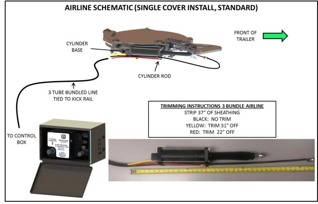
11 INSTALLATION GUIDE AIR-LINE ROUTING From the trailer air reservoir or the air line supplying air to the air ride suspension, connect the supply air to the control box using the supplied equal tee. (Fig. 8). We recommend a trailer protection valve be used. Typical connection is after the trailer protection valve that supplies air to the air ride suspension. There must be constant air to the control box for proper operation of the seal. Fig.8
12 INSTALLATION GUIDE


13 INSTALLATION GUIDE CONTROL BOX MOUNTING The control box has 4 holes with 1/4-20 thread in the rear of the box.


14 INSTALLATION GUIDE DRIVER TRAINING PIVOTAL EDGE VALVE AND OPERATION FLANGE CLEANING VIA AIR PURGE PERFORM EVERY TIME AFTER UNLOADING! A FAST AND EASY WAY TO KEEP YOUR LID OPERATING WELL DAY IN AND OUT! INSTRUCTIONS: 1. AFTER UNLOAD IS COMPLETE, DECREASE TANK PRESSURE TO 2-3psi 2. PULL PIVOTAL EDGE CONTROL BOX KNOB TO DEFLATE SEAL THIS WILL ALLOW THE PRESSURE TO PURGE BETWEEN THE COVER AND THE FLANGE CLEARING EXCESS MATERIAL FROM THE OPENING 3. OPEN TRAILER SAFETY BLOW DOWN VALVE 4. RESEAL COVER BY PUSHING IN THE PIVOTAL EDGE CONTROL KNOB


15 INSTALLATION GUIDE AIRLINE COLOR CODING Red=Rod-end of cylinder Yellow (or green for metric)=base-end of cylinder 3/8 or 10mm black is supply and seal. INNER BOX DECAL/VALVE OPERATING INSTRUCTIONS

16 GENERAL MAINTENANCE SERVICING THE PIVOTAL EDGE COVER Open the cover then close the supply air ball valve. Cycle the switches several times to relieve all accumulated pressure on the system. Disconnect the seal air line at the quick-connect by the cover. Lift the cover up using equal pressure. Remove the 3/8 fitting and hose clamp on the end of the seal inflation tube. Loosen the two slider screws on either side of the seal inflation tube. Remove the seal. Clean all surfaces, check and replace any visibly worn parts paying attention to the seal groove. Reassemble the seal and connections. Tighten the two slider screws. Connect air line and check for clearance. The hinge pin assembly should be checked for smooth operation. Remove the cylinder rod eye bolt (2 3/4 wrenches) Note: Seal Installation: The ring that the seal seats into needs to be clean. Start by feeding the inflation tube through the hole. A small amount of soapy water on the tube and seal will help this process. Press the seal into the groove at four equal points around the seal. Work the seal into the groove using your fingers and thrust washer. TROUBLESHOOTING 1. The operation of the cover should be smooth and easy. a. If not clean buildup on and around the flange and cover. Pay attention to under the ears also. 2. Leaks when starting to pressurize the tank. a. Deflate the seal by pulling the control valve knob to deflate the seal, thereby purging the tank pressure, wait a few seconds and push the knob back in to inflate the seal no more than 4psi. b. Reduce unloading pressure. Check seal integrity when possible. 3. Tanker Operating Pressure Required Seal Operating Pressure 2.0 Bar (29.0 PSI) 3.3 Bar or (48 PSI) 2.5 Bar (36.3 PSI) 3.7 Bar (54 PSI)
17 GENERAL MAINTENANCE (continued) CLEANING Moisture will result in product bonding between the cover and flange. Purging will not remove this hardened material and it will continue to build up over time. We recommend opening the lid and inspecting the entire surface of the flange for product buildup that needs to be scraped away. This should be done weekly at first. Then adjust accordingly to what is necessary based on your loading conditions. An air operated needle scaler is the best tool to use for cleaning product buildup.
, needle scaler.")
18 PREVENTIVE MAINTENANCE PIVOTAL EDGE PNEUMATIC HATCH (ASSEMBLY TOOLS AND MATERIALS THAT MY BE REQUIRED 2 x Channel lock pliers, rubber or plastic hammer, anti-seize, dry lubricant, wire brush, emery cloth, small pry bar, 3/4 socket, scraper (putty knife), needle scaler. MAINTENANCE PROCEDURE REMOVE & INSPECT COVER Close the supply air ball valve and deflate the seal by pulling the control box button out. Cycle the switches several times to relieve all accumulated pressure on the system. Disconnect the airline at the control box for the rod, and base line. Disconnect the seal airline at the quick-connect by the cover. Remove the nut at the rod end of the cylinder (two 3/4 wrenches). Remove the hinge pin D ring, plastic cover and 1.5 castle nut. Lift the cover up using equal pressure. Remove the 3/8 fitting and hose clamp on the end of the seal inflation tube. Loosen the two slider screws on either side of the seal inflation tube. Remove the seal. Clean all surfaces, check and replace any visibly worn parts paying attention to the seal groove. Reassemble: the seal (see note 1) and connections, hinge pin, use anti-seize on threads, set tension hand tight loosen to closest hole if necessary, check for smooth operation prior to connecting actuator. Connect airline and check for clearance. Connect the cylinder. Open and close the cover by hand checking for smooth operation. Connect the airlines, turn on air supply and cycle the cover. NOTE 1 Seal installation: The ring that the seal seats into needs to be clean. It is helpful to use an air powered needle scaler. Start by feeding the inflation tube through the hole, a small amount of soapy water on the tube and seal will help this process. Press the seal into the groove at four equal points around the seal. Work the seal into the groove using your fingers and thrust washer. Upon completion the seal should be flush or slightly recessed with the cover edge.

19 PREVENTIVE MAINTENANCE SAE STANDARD BOLT, P/N Rev IR-4

20 Bill of Materials SAE STANDARD BOLT, P/N Rev IR-4 ITEM NO. PART NUMBER Rev DESCRIPTION QTY B SEAL, INFLATABLE NA HOSE CLAMP, INFLATION TUBE A NUT, CLEVIS 1/2" DIA NA HINGE PIN THRUST WASHER NA WASHER, FLAT 14MM NA HINGE PIN D-RING NA SCREW, CS 1/4-20 X 1/ NA 1/4 NPT X 3/8 TUBE STRAIGHT NA NUT, NYLOC 5/ NA 1/2-20 X 2 HEX BOLT NA 1/2-20 NYLOK NUT NA 5/8" SAE Galvanized Washer NA CLEVIS PIN, 1/2 x 2-1/ NA HAIR PIN A HINGE PIN NA RETAINING RING, 1.5" NA HOSE BARB TO 1/4 NPT FEM NA HINGE PIN CAP ROUND B CUSTOM CASTLE NUT C 3 X 6 COMPOSITE CYLINDER NA BUSHING, NYLON HINGE PIN NA HEX BOLT, 1/2-20 X 1.25" WASHER, 5/8 x 2.25 x 1/ NA HEX BOLT, 5/8-11 x 4.5" NA SHCS 3/8-16 x 1.25" NA CLEVIS PIN, 6" NA BOLT 5/8-11X2.0 GR NA 1/2-13 X 1.0 HEX BOLT IR-1 MACHINED COVER, 6 BOLT IR-1 PIVOT BRACKET IR-1 PIVOT ATTACHMENT IR-2 COVER ATTACHMENT B COVER STANDOFF IR-1 SLIDER, OUTER IR-1 SLIDER, INNER IR-1 LOCK BAR STANDOFF IR-2 MACHINED FLANGE, 6 BOLT IR-2 CYLINDER MOUNT BRACKET IR-2 LOCK BAR 1
21 Exploded View SAE STANDARD BOLT, P/N Rev IR-4
22 FACTORY TESTING SETUP AND PRESSURE TEST PROCEDURE Covers are visually inspected for shipping damage. The hinge pin bushing and slide are installed. The lower flange is bolted to the test stand following the star pattern. The flange is mounted to the test stand and the mounting bolts are torqued in 5lbs increments to a torque of 15ft/lbs. Cover setup The seal retainer is installed and the hinge pin bushing is installed. The cover slider is mounted. The inflatable seal is installed and condition of the seal groove and seal are checked. The cover is mated to the lower flange on the test stand and hinge pin is installed. Operation check The cover is checked for smooth operation and clearance. Actuation is installed and connections are made to the control box. A minimum of 15 cycles are run. The cover is closed with the seal inflated to a pressure of 65 psi. Pressure is applied to the test chamber to 50 psi and the supply line is shut off. The cover is disassembled and stamped with a serial number and put into inventory or prepared for shipping. If you have any questions our website will generally provide your answer. 1(701) Office 1(701) Jay s Cell 1(701) Roger s Cell AN ISO 9001 COMPANY
Installation Notes: #86000-R Race Series +3.5 L/T Kit
 159 North Maple St. Unit J, CORONA CA 92880 P. 951-737-9682 F. 951-737-9006 WWW.CHAOSFAB.COM Installation Notes: #86000-R Race Series +3.5 L/T Kit Factory manual is recommended for removal and re-installation
Collection System. Please read the operator s manual carefully and make sure you understand the instructions before using the machine.
 Collection System 967004601 Please read the operator s manual carefully and make sure you understand the instructions before using the machine. 2012 All rights reserved. Swainsboro, GA. Printed in U.S.A.
INSTALL MANUAL. FOR ON LINE ORDERING- E Commerce Visit Our Website
 INSTALL MANUAL FOR ON LINE ORDERING- E Commerce Visit Our Website WWW.PRESSUREGUARD.COM Contact Information Technical Support: Chris@pressureguard.com Sales Support: Sales@pressureguard.com By Phone: 615-227-6024
NOTE: Visit our website at for video repair procedures, under the Tools section.
 Repair Instructions Hypro Repair Tools: Tool Box No. 3010-0168 1/4" Allen Wrench No. 3020-0008 Support Bars (2) No. 3010-0064 Port Brush No. 3010-0066 1/16" Allen Wrench No. 3020-0009 Brush Holder No.
69-74 VW Beetle IRS Rear Kit Part No
 www.airliftcompany.com 69-74 VW Beetle IRS Rear Kit Part No. 75615 MN-476 (01102) ECN 3455 Please read these instructions completely before proceeding with installation A C B E D AA F F ITEM QTY. PART
POWER STEERING PUMP REBUILDING SPK101 Read instructions completely before removal & disassembly
 POWER STEERING PUMP REBUILDING SPK101 Read instructions completely before removal & disassembly DISASSEMBLY: 1. Remove pump from car and allow to drain. 2. Remove pulley from front of pump. This requires
AVK SERIES 41 SWING CHECK VALVE FIELD MAINTENANCE AND INSTRUCTION MANUAL FOR SWING CHECK VALVES 3" - 12"
 AMERICAN AVK COMPANY AVK SERIES 41 SWING CHECK VALVE FIELD MAINTENANCE AND INSTRUCTION MANUAL FOR SWING CHECK VALVES 3" - 12" TABLE OF CONTENTS EXPLODED ASSEMBLY / PARTS LIST INTRODUCTION / DESCRIPTION
Maintenance Information
 80234313 Edition 1 June 2006 Air Grinder, Die Grinder, Sander and Belt Sander Series G1 (Angle) Maintenance Information Save These Instructions WARNING Always wear eye protection when operating or performing
 9000 LB Rolling Air Jack Installation, Operation and Repair Parts Information NOTICE - AIR SUPPLY MUST HAVE IN-LINE FILTER/REGULATOR/LUBRICATOR (NOT INCLUDED) TO VALIDATE THE ROLLING AIR JACK WARRANTY
Maintenance Information
 80234313 Edition 2 May 2014 Air Grinder, Die Grinder, Sander and Belt Sander Series G1 (Angle) Maintenance Information Save These Instructions Product Safety Information WARNING Failure to observe the
HIGH PRESSURE CONTROL VALVE PISTON BALANCED
 PISTON BALANCED All Rights Reserved. All contents of this publication including illustrations are believed to be reliable. And while efforts have been made to ensure their accuracy, they are not to be
FOR FUTURE REFERENCE SERIES 93HPS
 Hypro Series 93HPS Hydraulically Driven Wetseal Multistage Pumps Repair Manual KEEP FOR FUTURE REFERENCE Form L-1578R Rev. A SERIES 93HPS Hydraulically Driven Stainless Steel Multistage Centrifugal Pumps
AVK SERIES 41 SWING CHECK VALVE FIELD MAINTENANCE AND INSTRUCTION MANUAL FOR SWING CHECK VALVES 3" - 12"
 AMERICAN AVK COMPANY AVK SERIES 41 SWING CHECK VALVE FIELD MAINTENANCE AND INSTRUCTION MANUAL FOR SWING CHECK VALVES 3" - 12" TABLE OF CONTENTS EXPLODED ASSEMBLY / PARTS LIST INTRODUCTION / DESCRIPTION
82-01 Chevy S-10/ GMC Sonoma Front Kit Part No B
 www.airliftcompany.com 82-01 Chevy S-10/ GMC Sonoma Front Kit Part No. 75512B MN-481 (02105) ECN 3549 Please read these instructions completely before proceeding with installation Left Side Upper Shock
PV4 - Compact Shut Off Style Pig Valve IOM - Installation, Operation & Maintenance
 ACECO Valve P.O. Box 9 Mounds, Oklahoma 74047 PV4 - Compact Shut Off Style Pig Valve IOM - Installation, Operation & Maintenance Doc. No.: IOM-PV4-.0 Date: 6/0-00 Revision: A Contents: Installation Operation
ALL AMERICAN BILLET. Front Drive System - Small Block Ford Installation Instructions
 ALL AMERICAN BILLET Front Drive System - Small Block Ford Installation Instructions Small Block Ford with AC & PS All American Billet Store (800) 764-0926 www.allamericanbilletstore.com Items needed for
INSTALLATION INSTRUCTIONS Part# , , ,
 INSTALLATION INSTRUCTIONS Part# 20-0218, 22-0318, 20-0118, 22-0219 20-0218 - 4 Tire On Board Air Delivery System and Dual Compressed Air System Includes ARB CKMTA12 Compressor 20-0118 - 2017 FORD RAPTOR
OWNERS MANUAL. GMC C K AND 19K GVW CHASSIS CAB 2004-NEWER MODELS (Link Part No. 8M000050) PROUDLY INSTALLED BY : COMPANY : INSTALLER SIGNATURE :
 PROUDLY INSTALLED BY : COMPANY : INSTALLER SIGNATURE :") OWNERS MANUAL GMC C5500 15K AND 19K GVW CHASSIS CAB 2004-NEWER MODELS (Link Part No. 8M000050) Link Mfg. Ltd. 223 15th St. N.E. Sioux Center, IA USA 51250-2120 (712) 722-4868 Fax (712) 722-4779 QUESTIONS?
OWNERS MANUAL GMC C5500 15K AND 19K GVW CHASSIS CAB 2004-NEWER MODELS (Link Part No. 8M000050) Link Mfg. Ltd. 223 15th St. N.E. Sioux Center, IA USA 51250-2120 (712) 722-4868 Fax (712) 722-4779 QUESTIONS?
<THESE INSTRUCTIONS MUST BE GIVEN TO THE END USER> B&W Trailer Hitches 1216 Hawaii Road / PO Box 186 Humboldt, KS P: F:
 B&W Trailer Hitches 26 Hawaii Road / PO Box 86 Humboldt, KS 66748 P:620.473.3664 F:620.869.903 Ford OEM Mount System Installation Instructions 20,000
Model ES-660-HF High Flow Spring-Loaded Hatch
 Instruction Manual Model ES-660-HF February 2015 Model ES-660-HF High Flow Spring-Loaded Hatch Table of Contents Introduction...1 Specifications...2 Principle of Operation...2 Tagging Information...2 Installation
METERING VALVE 2" STEM GUIDED
 2" STEM GUIDED All Rights Reserved. All contents of this publication including illustrations are believed to be reliable. And while efforts have been made to ensure their accuracy, they are not to be construed
OWNERS MANUAL GM C4500/C5500 DANA MODEL S135 REAR AXLE 2003-NEWER MODELS LINK MFG. PART NO. 8M PROUDLY INSTALLED BY : COMPANY :
 OWNERS MANUAL GM C4500/C5500 DANA MODEL S135 REAR AXLE 2003-NEWER MODELS LINK MFG. PART NO. 8M000030 Link Mfg. Ltd. 223 15th St. N.E. Sioux Center, IA USA 51250-2120 (712) 722-4874 Fax (712) 722-4876 QUESTIONS?
ATLAS TRANSFER CASES CABLE SHIFTER units built after 5/1/12
 KIT CONSISTS OF: No. Qty Part No. Description P.O. Box 247, 4320 Aerotech Center Way PAGE 1 OF 6 Page Rev. Date: 08-01-17 1 1 302051 BASE- TWIN STICK MOUNT 2 1 302060 BOOT- TWIN STICK 3 1 302063 BOOT RING-
MODEL 5120 Tire Repair Station
 MODEL 5120 Tire Repair Station 00-0049 Installation, Operation & Repair Parts Information Branick Industries, Inc. 4245 Main Avenue P.O. Box 1937 Fargo, North Dakota 58103 REV01182017 P/N: 81-0058G CAUTION
DeZURIK " BAW AWWA BUTTERFLY VALVES WITH EPOXY-RETAINED SEAT
 DeZURIK 20 144" BAW AWWA BUTTERFLY VALVES WITH EPOXY-RETAINED SEAT Instruction D10373 April 2017 Instructions These instructions provide information about the 20 (250 F2 model only) and the 24-144 BAW
DESCRIPTION Acura TSX SUSPENSION Front - TSX. NOTE: For system description and component location, see Fig. 1.
 2004 SUSPENSION Front - TSX DESCRIPTION NOTE: For system description and component location, see Fig. 1. Fig. 1: Identifying Front Suspension Components Wednesday, March 12, 2008 8:30:45 8:30:55 PM Page
H Low Torque Impact Wrench
 SERVICE MANUAL H8508-3 Low Torque Impact Wrench Serial Code AKW Read and understand all of the instructions and safety information in this manual before operating or servicing this tool. Register this
MODEL EF Full Circle Tire Spreader
 MODEL EF Full Circle Tire Spreader Installation, Operation & Repair Parts Information Branick Industries, Inc. 4245 Main Avenue P.O. Box 1937 Fargo, North Dakota 58103 REV. 062917 P/N: 81-0050C CAUTION
INSTALLATION, OPERATING AND MAINTENANCE INSTRUCTIONS D SERIES TABLE OF CONTENTS
 INSTALLATION, OPERATING AND MAINTENANCE INSTRUCTIONS D SERIES GENERAL INFORMATION TERMS CONCERNING SAFETY UNPACKING INSTALLATIONS VALVE MAINTENANCE TABLE OF CONTENTS VALVE DISASSEMBLY AND REASSEMBLY PLUG
Hydraulic Motors Repair Instructions
 Hydraulic Motors Repair Instructions Motors for Global External Hydraulic Vibrators Models 2HC - pn #251020 5HC - pn #251050 Global Manufacturing, Inc. 101 E 22nd St Little Rock, Arkansas 2206 V I B R
Kits 75559, & Universal Air Spring-Over-Strut
 Kits 75559, 75561 & 75562 Universal Air Spring-Over-Strut MN-723 (061901) ECR 8657 NOTE: THIS KIT IS SOLD WITHOUT A WARRANTY. INSTALLATION GUIDE For maximum effectiveness and safety, please read these
FRONT STABILIZER BAR KIT
 FRONT STABILIZER BAR KIT P/N 2881205 APPLICATION RZR XP 1000 MY16 and Newer, RZR XP 4 1000 MY16 and Newer BEFORE YOU BEGIN Read these instructions and check to be sure all parts and tools are accounted
Maintenance Information
 04581245 Edition 2 May 2014 Air Grinder, Die Grinder and Sander Series G2 (Angle) Maintenance Information Save These Instructions Product Safety Information WARNING Failure to observe the following warnings,
P/N Figure 1. Figure 2. 3 Valve Stem
 P/N 80523 BY MN-75 (12612) ECN1965 ECR 8167 3 Valve Stem 2 1 Figure 1 1 1. Jack up front end of vehicle and place safety stands under axle. Remove front wheels and lower shock absorber attaching bolts.
PLOW MOUNT GLACIER PRO KIT
 PLOW MOUNT GLACIER PRO KIT P/N 2880262 APPLICATION FOR USE WITH THE GLACIER PRO MID-SIZE PLOW SYSTEM (P/N 2880260) ON 2015 AND NEWER RZR 00 MODELS BEFORE YOU BEGIN Read these instructions thoroughly and
Model DFR 070/156/220 Rotary Actuator
 Figure 1 DFR 156 TABLE OF CONTENTS General 2 Actuator Assembly 18 Scope 2 Bushing / Yoke Assembly 18 Principles of Operation 2 Spring Barrel Assembly 18 Safety Caution 2 Diaphragm Plate Assembly 20 Specifications
Kinze 3000 Series Row Unit. Hydraulic Actuator Installation Instructions PN: ENG REV. A
 Kinze 3000 Series Row Unit Hydraulic Actuator PN: 2006428-ENG REV. A Installation Overview Required Parts Part Number Qty * Description 4003011 1 HYDRAULIC ACTUATOR ASSY. (INCLUDES MOUNTING HARDWARE) 4003458
THE GLIDER 5th Wheel Attachment
 April 2007 APPLICATION: INSTALLATION INSTRUCTIONS MODEL NO. 70460 70046 THE GLIDER 5th Wheel Attachment For use on short bed pickup applications US Patent No. 6247720 COMPLETE PARTS LIST Part Description
Installation Instructions COMPETITION/PLUS SHIFTER Ford Mustang MT82 6-Speed Manual Transmission Catalog#
 Installation Instructions COMPETITION/PLUS SHIFTER 2015-2017 Ford Mustang MT82 6-Speed Manual Transmission Catalog# 3916037 Rev. 00 WORK SAFELY! For maximum safety, perform this installation on a clean,
H2O-C14 AAA FINE FINISH SERIES PUMP OUTFIT
 PRODUCT INFORMATION H2O-C14 AAA FINE FINISH SERIES PUMP OUTFIT The H2O-C14 AAA pump system is an air assisted airless unit which combines airless and conventional or HVLP air atomization technologies to
1988 Chevrolet Pickup V SUSPENSION - FRONT (4WD)' 'Front Suspension - "V" Series 1988 SUSPENSION - FRONT (4WD) Front Suspension - "V" Series
' 'Front Suspension - V Series 1988 SUSPENSION - FRONT (4WD) Front Suspension - V Series") 1988 SUSPENSION - FRONT (4WD) Front Suspension - "V" Series DESCRIPTION NOTE: Vehicle serial numbers used in this article has been abbreviated for common reference to Chevrolet and GMC models. Chevrolet
1988 SUSPENSION - FRONT (4WD) Front Suspension - "V" Series DESCRIPTION NOTE: Vehicle serial numbers used in this article has been abbreviated for common reference to Chevrolet and GMC models. Chevrolet
Maintenance Information
 16572679 Edition 2 May 2014 Air Drill QP Series Maintenance Information Save These Instructions Product Safety Information WARNING Failure to observe the following warnings, and to avoid these potentially
Instalation, Operation and Maintenance Manual
 POWER BALL VALVE Instalation, Operation and Maintenance Manual Rev. 1 1 of 23 INDEX PAGE 1.0 INTRODUCTION-----------------------------------------------------------------------------4 2.0 RECEIVING & PREPARATION
Part # Chevy Level 2 Air Suspension Package One Piece Frame
 350 S. St. Charles St. Jasper, In. 47546 Ph. 812.482.2932 Fax 812.634.6632 www.ridetech.com Part # 11020299 55-57 Chevy Level 2 Air Suspension Package One Piece Frame Front Components: 1 11013001 Master
DISPLACEMENT PUMP INSTRUCTIONS-PARTS LIST Rev. K. Model , Series A Model , Series B Model , Series A
 INSTRUCTIONS-PARTS LIST INSTRUCTIONS This manual contains important warnings and information. READ AND KEEP FOR REFERENCE. DISPLACEMENT PUMP 308190 Rev. K 3000 psi (210 bar) MAXIMUM WORKING PRESSURE Model
CP-1, CP-2, CP-2L & CPD-2 Series Overhaul
 Replacement of Mechanical Seals for CM, CMU, CS and CSU Series Pumps Installation Instructions Form No. F-1031 Section 5013 Issue Date 03/01/85 Rev. Date 02/08/11 CP-1, CP-2, CP-2L & CPD-2 Series Overhaul
Maintenance Information
 16573370 Edition 2 February 2014 Air Grinder 99V Series Maintenance Information Save These Instructions Product Safety Information WARNING Failure to observe the following warnings, and to avoid these
<THESE INSTRUCTIONS MUST BE GIVEN TO THE END USER> B&W Trailer Hitches 1216 Hawaii Road / PO Box 186 Humboldt, KS P: F:
 B&W Trailer Hitches 26 Hawaii Road / PO Box 86 Humboldt, KS 6678 P:620.73.366 F:620.869.903 Ford OEM Mount System Installation Instructions 20,000 LBS.
INSTALLATION INSTRUCTIONS
 INSTALLATION INSTRUCTIONS GMT 560 (4500/5500) CREW CAB (2351A000) Link Mfg. Ltd. 223 15th St. N.E. Sioux Center, IA USA 51250-2120 The CABMATE MODEL 2351A000 fits the 2003 and later GM 4500 / 5500 crew
HIGH RISE POWER ANGLE KIT
 HIGH RISE POWER ANGLE KIT P/N 33-0100 OWNER S MANUAL Application HIGH RISE PUSH TUBE 33-0000 & 34-0000 ATTENTION DEALER: CUSTOMER MUST RECEIVE A COPY OF THIS MANUAL AT THE TIME OF SALE. Before you begin,
FRP Ball Valves INSTALLATION & MAINTENANCE MANUAL
 FRP Ball Valves INSTALLATION & MAINTENANCE MANUAL FRP BALL VALVES TABLE OF CONTENTS MAINTENANCE AND INSTALLATION INSTRUCTIONS 1. 2. 2.1 2.2 2.3 2.4 GENERAL...Page 1 HANDLING...1 Receiving and Storing...1
INSTALLATION INSTRUCTIONS
 PZ 60 inch Side Discharge Deck Kit - 966555302 Tools Required ½" socket or wrench (battery terminals, strut shaft). ½" breaker bar with 2-3" extension (relieve tension on idler arms). Refer to Operators
B14 AAA FINE FINISH SERIES PUMP OUTFIT
 PRODUCT INFORMATION B14 AAA FINE FINISH SERIES PUMP OUTFIT The B14 AAA pump system is an air assisted airless unit which combines airless and conventional or HVLP air atomization technologies to produce
RYOBI 10 INCH COMPOUND MITER SAW MODEL NO. TS1350 REPAIR SHEET
 RYOBI 10 INCH COMPOUND MITER SAW MODEL NO. TS1350 REPAIR SHEET 1 FIGURE A 36 26 25 24 SEE FIGURE B 23 27 20 28 29 30 35 31 37 33 2 10 22 11 12 9 21 13 14 17 16 15 32 18 31 19 34 SEE FIGURE D 8 6 5 4 2
1984 Dodge W250 PICKUP
 1984 Dodge W250 PICKUP Submodel: Engine Type: V8 Liters: 5.2 Fuel Delivery: CARB Fuel: GAS Dana 44 MODELS THROUGH 1984 2. Raise and safely support the vehicle, then remove the wheel hub and bearings as
! Williams Machine & Tool 204 Plastic Lane Pump Serial No. Monticello, IA USA
 NOTICE: This manual is to remain with truck after pump unit is installed. MACHINE & TOOL Hydraulic Piston Pump Units Operating, Mounting and Safety Instructions for: Model 20 Pump Model 40 Pump Model F98
Installation Instructions Capacity 10,000 lbs. (100 Series Lift)
") Installation Instructions Capacity 10,000 lbs. (100 Series Lift) IMPORTANT Reference ANSI/ALI ALIS, Safety Requirements for Installation and Service of Automotive Lifts before installing lift. OPERATING
Installation Instructions Capacity 10,000 lbs. (100 Series Lift) IMPORTANT Reference ANSI/ALI ALIS, Safety Requirements for Installation and Service of Automotive Lifts before installing lift. OPERATING
HYDRAULICS. TX420 & & lower. Hydraulic Tandem Pump Removal. 4. Remove the LH side panel (Fig. 0388).
.") TX420 & 425 240000299 & lower 4. Remove the LH side panel (Fig. 0388). Hydraulic Tandem Pump Removal Note: Cleanliness is a key factor in a successful repair of any hydraulic system. Thoroughly clean all
TX420 & 425 240000299 & lower 4. Remove the LH side panel (Fig. 0388). Hydraulic Tandem Pump Removal Note: Cleanliness is a key factor in a successful repair of any hydraulic system. Thoroughly clean all
Front Suspension 2015 E-Series REMOVAL AND INSTALLATION Procedure revision date: 08/11/2014. Axle
 204-01 Front Suspension 2015 E-Series REMOVAL AND INSTALLATION Procedure revision date: 08/11/2014 Axle 1 N620604 Axle pivot nut 2 N806859 Axle pivot bolt 3 3007 LH/ 3006 RH LH/ 3006 RH Axle Removal NOTICE:
KHR Series Regulators
 KHR Series Regulators Maintenance Instructions Kit Contents retainer Poppet Poppet spring Poppet damper Outer body seal Inner body seal Upper piston seal seal backup ring Main piston seal vent seal Self-vent
B&W Trailer Hitches 1216 Hawaii Road / PO Box 186 Humboldt, KS P: F:
 B&W Trailer Hitches 1216 Hawaii Road / PO Box 186 Humboldt, KS 66748 P:620.473.3664 F:620.473.3766 NOTE: We recommend reading instructions before beginning the installation. GM OEM Mount System Slider
Service Manual Air Tech Second Stage
 Service Manual Air Tech Second Stage Copyright 2002, Cressi-sub Revised 3/2002 2 Air Tech Second Stage Service Manual Contents BEFORE STARTING... 3 DISASSEMBLY... 3 PARTS CLEANING AND LUBRICATION... 9
CHAMBER CUSTOMIZATION GUIDE TSE
 Revision Date: May 6, 2011 Revision: 3 Page: 1 of10 CONTENTS Brake Chamber Clamp Repositioning Instructions...2-3 Mechanical Release of Spring Brakes (Caging)...4-6 Determine The Correct Push Rod Length...7-9
INSTALLATION - MAINTENANCE MANUAL Severe Service Series M4 Ball Valve
 INSTALLATION - MAINTENANCE MANUAL Severe Service Series M4 Ball Valve Date: May 2016/ Page 2 of 12 Table of Contents 1. Safety Information - Definition of Terms..........................2 2. Bill of Materials....................................
LIMITED SLIP DIFFERENTIAL INSTALLATION
 Installation of the limited slip gear can be done with axle out of car or with car lifted to gain access from underneath. Refer to repair manual for proper lifting instructions if car is to be lifted.
LOW PRESSURE BALANCED VALVE DIAPHRAGM BALANCED
 DIAPHRAGM BALANCED All Rights Reserved. All contents of this publication including illustrations are believed to be reliable. And while efforts have been made to ensure their accuracy, they are not to
INSTALLATION, OPERATION & MAINTENANCE INSTRUCTIONS
 June 2004 INSTALLATION, OPERATION & MAINTENANCE INSTRUCTIONS Please be sure that this document is given to the end user of this product. It contains many important items relating to the proper usage of
Post Driver Attachment
 Attachment (Shown with Optional Power Cell Rotator) Models - 600, 850 Safety Instructions This safety alert symbol indicates important safety messages in this manual. When you see this symbol, carefully
Please read these instructions completely before proceeding with installation. Read all maintenance guidelines on page 7 before operating the vehicle.
 MN-643 (02511) ECR 5461 Kit No. 39205 Please read these instructions completely before proceeding with installation Item P/N Description Quantity A 26391 Driver-Side Beam Assembly 1 B 26414 Passenger-Side
Miniature Soft Seat Fluid Pressure Regulator
 Instruction Sheet P/N 1. Description The Nordson miniature soft seat fluid pressure regulator is designed for use with hydraulic and pneumatic medias. The regulator body and wetted parts are constructed
StarTrac E-SM StairMill Install Guide
 StarTrac E-SM StairMill Install Guide ASSEMBLY AND SETUP TOOLS REQUIRED Most STAR TRAC E-SM StairMill can be assembled using the following tools (not included): Metric Hex Key Wrenches Metric Open-End
Model 3770 WARNING. Failure to comply with the safety information in these instructions could result in serious injury or death.
 B&W Trailer Hitches 1216 Hawaii Road / PO Box 186 Humboldt, KS 66748 P:620.473.3664 See Limited Lifetime Warranty at F:620.869.9031 bwtrailerhitches.com/warranty NOTE: We recommend reading instructions
<THESE INSTRUCTIONS MUST BE GIVEN TO THE END USER> B&W
 B&W Trailer Hitches 26 Hawaii Road / PO Box 86 Humboldt, KS 6678 P:620.73.366 F:620.869.903 GM Puck Mount System Installation Instructions 20,000 LBS.
SERVICE INSTRUCTIONS FOR SEAL REPLACEMENT OF POWER GEAR HYDRAULIC LEVELING LEGS
 SERVICE INSTRUCTIONS FOR SEAL REPLACEMENT OF POWER GEAR HYDRAULIC LEVELING LEGS 82-L0352 REV 8 4-27-2011 WARNING! HYDRAULIC COMPONENTS CAN CAUSE SERIOUS INJURY OR DEATH IF PROPER SAFETY PRECAUTIONS ARE
Hose Reel Kit for Multi-Pro 1200 and 1250 Sprayers. Installation Instructions. Form No Model No Serial No.
 Hose Reel Kit for Multi-Pro 00 and 50 Sprayers Model No. Serial No. 000000 and Up Form No. 9-8 Installation Instructions Installation Important You will need to purchase Teflon tape before installing this
Front Drive System - Big Block Chevy Installation Instructions Big Block Chevy with AC & with PS
 Front Drive System - Big Block Chevy Installation Instructions Big Block Chevy with AC & with PS All American Billet Store (800) 764-0926 www.allamericanbilletstore.com Items needed for install Jack Jack
Sachs shock manual. ( ) 2 & 4 Stroke RR Enduro. ( ) RS Dual Sport
 2 & 4 Stroke RR Enduro. ( ) RS Dual Sport") Sachs shock manual (2013 2015) 2 & 4 Stroke RR Enduro (2014-2015) RS Dual Sport 1 Introduction The procedures in this manual must take place in a clean environment using professional tools and some specific,
Sachs shock manual (2013 2015) 2 & 4 Stroke RR Enduro (2014-2015) RS Dual Sport 1 Introduction The procedures in this manual must take place in a clean environment using professional tools and some specific,
Maintenance Information
 16606022 Edition 3 May 2014 Air Drill 728 Series Maintenance Information Save These Instructions Product Safety Information WARNING Failure to observe the following warnings, and to avoid these potentially
ST 93 RIPPER INSTALL KIT
 ST 93 RIPPER INSTALL KIT P/N 2883777;2883778;2883779 APPLICATION The Timbersled Ripper ST93 Install Kit is designed to fit all Timbersled ST90 and ST93 Ripper models. This includes; Timbersled Model No.
PERFORMANCE SUSPENSION PARTS
 PERFORMANCE SUSPENSION PARTS Introduction Air Lift Performance The purpose of this publication is to assist with the installation, maintenance and troubleshooting of this Chrysler LX, LD, LC Platform 300C,
Kit No Please read these instructions completely before proceeding with installation. Parts List G J I K L H CC FF DD MN-505 (01201) NPR 3733
 NPR 3733") Kit No. 57154 MN-505 (01201) NPR 3733 Please read these instructions completely before proceeding with installation Parts List by www.airliftcompany.com Item P/N Description Quantity A 58407 Air Spring
Kit No. 57154 MN-505 (01201) NPR 3733 Please read these instructions completely before proceeding with installation Parts List by www.airliftcompany.com Item P/N Description Quantity A 58407 Air Spring
B&W Trailer Hitches 1216 Hawaii Road / PO Box 186 Humboldt, KS P: F:
 B&W Trailer Hitches 1216 Hawaii Road / PO Box 186 Humboldt, KS 66748 P:620.473.3664 F:620.869.9031 NOTE: We recommend reading instructions before beginning the installation. Ford OEM Mount System Slider
OWNERS MANUAL GM C4500/C5500 4X4 DANA MODEL S135 REAR AXLE 2005-NEWER MODELS LINK MFG. PART NO. 8M PROUDLY INSTALLED BY : COMPANY :
 OWNERS MANUAL GM C4500/C5500 4X4 DANA MODEL S135 REAR AXLE 2005-NEWER MODELS LINK MFG. PART NO. 8M000060 Link Mfg. Ltd. 223 15th St. N.E. Sioux Center, IA USA 51250-2120 (712) 722-4874 Fax (712) 722-4876
MT (10/19/07) Rev. 02 PARTS MANUAL
 Rev. 02 PARTS MANUAL") MT1741210 (10/19/07) Rev. 02 PARTS MANUAL Table Of Contents PRODUCT COMPONENTS PAGES Engine... 4 Frame... 6 Drive... 8 Auger Housing... 10 Discharge Chute... 12 Handle Assembly... 14 Shift Yoke... 16
MT1741210 (10/19/07) Rev. 02 PARTS MANUAL Table Of Contents PRODUCT COMPONENTS PAGES Engine... 4 Frame... 6 Drive... 8 Auger Housing... 10 Discharge Chute... 12 Handle Assembly... 14 Shift Yoke... 16
<THESE INSTRUCTIONS MUST BE GIVEN TO THE END USER> B&W Trailer Hitches 1216 Hawaii Road / PO Box 186 Humboldt, KS P: F:
 B&W Trailer Hitches 26 Hawaii Road / PO Box 86 Humboldt, KS 6678 P:620.73.366 F:620.869.903 RAM OEM Mount System Installation Instructions 25,000 LBS.
Model ET 5000W Operation and Service Manual
 Model ET 5000W Operation and Service Manual Patented 5/16 BALL Load Capacity: 5000 lbs The ET 5000W ESCALATE TRAILER offers ground level roll-on loading and roll-off unloading of equipment with non-tilting
Industrial Turbo Meters, Sizes 2" through 6"
 Industrial Turbo Meters Sizes 2" through 6" TUR-UM-00530-EN-19 (October 2014) User Manual Industrial Turbo Meters, Sizes 2" through 6" User Manual CONTENTS Scope of the Manual 5 Specifications 5 Product
BASEPLATE Ford F-150
 , Rev 0 02/18 BASEPLATE 9519318 Ford F-150 Pin Height- 15-1/2 Center- 34 ITEM PART # QTY DESCRIPTION 1 00057 2 WASHER,.25 SPRING LOCK 2 00059 4 WASHER, FLAT.375 3 00062 2 NUT.25NC HEX 4 00084 2.50 LOCKWASHER
B14 AAA FINE FINISH SERIES PUMP OUTFIT
 PRODUCT INFORMATION B14 AAA FINE FINISH SERIES PUMP OUTFIT The B14 AAA pump system is an air assisted airless unit which combines airless and conventional or HVLP air atomization technologies to produce
Technical Support Line: (952) Hanover Ave. Lakeville, MN
 Hanover Ave. Lakeville, MN") Technical Support Line: (952) 985-5675 Email: Sales@QA1.net 21730 Hanover Ave. Lakeville, MN 55044 www.qa1.net INSTALLATION INSTRUCTIONS QA1 1967-1979 Mopar A-Body Rear 6 link Conversion System QA1 p/n
Technical Support Line: (952) 985-5675 Email: Sales@QA1.net 21730 Hanover Ave. Lakeville, MN 55044 www.qa1.net INSTALLATION INSTRUCTIONS QA1 1967-1979 Mopar A-Body Rear 6 link Conversion System QA1 p/n
Frame. Axle. Kit No Please read these instructions completely before proceeding with installation. Figure 1. Kit Parts List FORWARD B J
 Kit No. 70 Please read these instructions completely before proceeding with installation by www.airliftcompany.com MN-7 (008) ECN 08 Item P/N Description Qty. A B C D E F H I 807 0770 0006 88 70 87 8 8
Part # WD & 2WD Jeep XJ Cherokee 3 Lift Now Manufactured With Chromolly Arms PRO COMP SUSPENSION. Suspension Systems that Work!
 PRO COMP SUSPENSION Suspension Systems that Work! Part # 55590 84-01 4WD & 2WD Jeep XJ Cherokee 3 Lift Now Manufactured With Chromolly Arms This document contains very important information that includes
'99-03 CHEVROLET/GMC IFS 4WD 6" SUSPENSION SYSTEM P/N INSTALLATION INSTRUCTIONS
 1/16/04 '99-03 CHEVROLET/GMC IFS 4WD 6" SUSPENSION SYSTEM P/N. 10-41099 INSTALLATION INSTRUCTIONS NOTE: Each Lift Kit and options to Lift Kits are packaged separately. Therefore, installation procedures
WD DODGE SUSPENSION LIFT KIT P/N
 4/03/03 94-01 4WD DODGE 1500 3 SUSPENSION LIFT KIT P/N 10-46094 NOTE: Each lift kit, and options to lift kits, are packaged separately. Therefore installation procedures are covered in separate instructions.
SHIMLESS INDUSTRIAL LINEAR BEARINGS
 08 LINEAR MOTION SHIMLESS INDUSTRIAL LINEAR BEARINGS Shimless Industrial Linear Bearings are designed to be used in both low and high acceleration/deceleration applications. The Shimless Industrial Linear
INSTALLATION INSTRUCTIONS FOR THE MOTOR TRIKE GL1500 RAKE KIT
 INSTALLATION INSTRUCTIONS FOR THE MOTOR TRIKE GL1500 RAKE KIT Thank you for choosing the Motor Trike GL1500 Rake Kit. We ask that you read the directions before you start and follow them very closely.
3.2 DRIVE TORQUE HUB. Roll, Leak and Brake Testing SECTION 3 - CHASSIS & TURNTABLE. 3-2 JLG Lift
 3.2 DRIVE TORQUE HUB Roll, Leak and Brake Testing 10 LUG PATTERN Torque-Hub units should always be roll and leak tested before disassembly and after assembly to make sure that the unit's gears, bearings
KIT No , and 80590
 KIT No. 80531, 80545 and 80590 by MN-354 (05603) ECR 5593 Please read these instructions completely before proceeding with installation Air Spring Kit Parts List Item Description Quantity A Air Spring
HPB45 and HPB55 Series Hydraulic Paving Breakers
 SERVICE MANUAL HPB45 and HPB55 Series Hydraulic Paving Breakers Serial Codes GMN, GMP, GMR, and GMT Read and understand all of the instructions and safety information in this manual before operating or
baseplate Chevrolet Equinox
 , Rev 3 06/16 baseplate 9518316 Chevrolet Equinox Pin height - 14-3/4 Centers - 24-1/4 25. ITEM PART # QTY DESCRIPTION 1 00057 2.25 LOCKWASHER 2 00059 8.375 FLATWASHER 3 00060 24.375 LOCKWASHER 4 00061