DigiDL Installation Guide Page - 2 DigiDL Installation Guide Page - 3
|
|
|
- Janice Williamson
- 6 years ago
- Views:
Transcription


1
2 Table of contents Checking compatibility of vehicles 4-5 Special Vehicle manufacturer considerations When to use DDL-DP - double plug adapter 6 Y Cable Secondary CAN-Bus adapter - DDL-CY 6 CAN-Bus termination plug for onboard systems DDL-TM 7 VDO and Secondary CAN-Bus enabling 8 CAN_Bus Baud Rates 8 Rear Security Seal 8 digidl connections 9-10 digidl Indicator Lights 11 digidl-e Model - Front Port download on VDO Tachographs. Plus unlocking the Front Port Installing digidl Configuration Windows software 16 Connecting the digidl to your PC 17 digidl Configuration - Device Window 18 digidl Configuration - Configuration Window - WIFI 19 Setting up a new SSID 19 digidl Configuration - Configuration Window - GPRS 20 digidl Configuration Options 21 digidl Configuration - Status Window 22 digidl Configuration - Files 23 Authentication of the Company Card 24 The role of digicentral 24 Troubleshooting 25 Overview of digicentral Web 26 DigiDL Installation Guide Page - 2 DigiDL Installation Guide Page - 3


3 DigiDL Checking compatibility Checking compatibility of vehicles: Remote Download was introduced in Many vehicles from 2010 will have compatible Digital Tachographs however it can be a mixed picture depending on the vehicle and Tachograph manufacturer and how much stock of old Tachographs were around. You can access a printed version of the tachograph model number in the printer tray area of most Tachographs. Checking Stoneridge Tachograph Model Numbers using Tacho File Viewer Stoneridge Compatibility: All revision 7.0 Tachographs onwards. VDO Compatibility: V1.3 onwards with significant exceptions and caveats. In the case of VDO a Secondary CAN-Bus, required for Remote Download, was not included on every one of their models. The deletion of the Secondary CAN mostly affects 12 volt models however there are many Volvo and some Renault that are affected. Tachosys supply a product called digidl-e that allows the use of the Tachograph Front Port for Remote download. You will also need the K-Line cable (DDL-Kline) with this solution. Technical Printout Tachosys Tachofileviewer If you need to use the front port for remote download on a VDO Tachograph you will need a VDO Front Interface Update Card. See Pages for further information. Checking VDO Tachograph Model Numbers Tachosys Compatibility Checking tools Tachosys are the most experienced manufacturer in this market and we have developed several methods to check Tachograph compatibility. 1) Tachosys TachoFile Viewer: you can download this tool from our website, Tachosys.com, free of charge and use it to view a file downloaded from the customers vehicle. The Identification section will reveal the model number of the Tacho. 2) Tacho Lookup is an online tool where you can lookup individual Tachograph model numbers and check compatibility. (lookup.tachosys.com) 3) Tacho-Lookup- Online: This is a fantastic batch checker. Simply place all of the customers vehicle download files in a single directory and this tool will provide a spreadsheet indicating compatibility of each vehicle. Contact Tachosys for the appropriate URL to download this tool. DigiDL Installation Guide Page - 4 DigiDL Installation Guide Page - 5


.")
 seem to have systems which are tapping into data from the CAN2 even though they are not doing remote download.")
 and our latest digidl configuration software we allow you to change the CAN2 address.")
4 digidl - Installation Specific Vehicle Manufacturer Considerations: Double Plug Adapter - DDL-DP Works in conjunction with DDL-TC (standard loom) for vehicles with a conjoined A and B plug at the rear of the Tachograph. Vehicles affected: Mercedes and Volvo Y Cable Secondary CAN-Bus adapter - DDL-CY Cont:- The standard CAN bus address for remote download is FB. This can be found in digidl Configuration under Features. (See image below). We suggest you change our device address to FA or FC. For shared devices use DDL-CY and if the third party device is not required use DDL-TM below. Vehicles most affected: Iveco, MAN, Mercedes, Scania and Volvo Volvo / Mercedes Plug Y Cable Secondary CAN-Bus adapter - DDL-CY In some cases a RED plug may already be inserted in the C Connector of the Tachograph for manufacturer or third party services. In most cases this can be removed and terminated (see DDL-TM connector Page 7). If information is required from the Tachograph for a third party service we provide a Y Connector which allows you to plug both devices into CAN C. Some 2015 onwards, vehicles (Scania and Volvo to date) seem to have systems which are tapping into data from the CAN2 even though they are not doing remote download. Both devices cannot share the same CAN address and the truck manufacturers do not provide a way to change their address. If you are running V1.33 firmware or later on your digidl (E, EX) and our latest digidl configuration software we allow you to change the CAN2 address. DigiDL Installation Guide Page - 6 CAN-Bus Termination plug DDL-TM for Onboard Systems 2012 onwards Some manufacturers fit a telematics unit as standard even if the operator does not subscribe to any services. This telematics unit may use the Tachograph to terminate their own CAN-Bus. If the Red Plug is removed from the Tacho errors may occur which are shown on the vehicle dashboard. Remove the manufacturer s or third party s Red plug and terminate it with our DDL-TM 120 Ohm resistor. To check for an active third party device, check voltage between GROUND and PIN 5 of their RED plug with the vehicle s ignition ON. It will read +/- 3V if active. Vehicles most affected: Iveco, MAN, Mercedes, Scania and Volvo DigiDL Installation Guide Page - 7

 and TCO Parameters CANBus CAN2 (ON).")
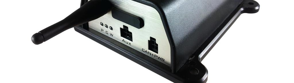
5 digidl - Installation VDO and secondary CAN-Bus enabling digidl Connections Some VDO Tachograph may be configured with the Secondary CAN-Bus disabled by default. In this case the function will need to be enabled with a CTC II programmer with 2.6 firmware or later or Stoneridge Optimo. digidl connections If the CAN LED (GREEN) LED does not illuminate on the digidl and the Tachograph has a Secondary CAN-Bus this is the likely cause. Fig 1. The VDO programmer settings as we know them are; Programming TCO Parameters CANBus Remote Download (ON) and TCO Parameters CANBus CAN2 (ON). This work although not classed as a full calibration will need to be done with a Workshop card installed. Vehicles most affected: DAF, Renault CAN-Bus Baud rates From 2012 onwards Mercedes upped the Baud Rate of their CAN-Bus and in turn the Tachograph s Secondary CAN. The digidl firmware was updated in version 1.18s to cope with this change. You must upgrade earlier versions of the firmware. Activity LED Indicators 1) Configuration Port or Auxiliary 2) VU Rear Connection (C) Vehicles most affected: Mercedes Rear security seal Vehicle Unit Rear Connections In circumstances where a rear security seal is fitted to the Tachograph, normally where the speed is being taken from the Tachograph, this must be refitted and resealed. Resealing can only be performed by a calibration station. The seal is not required by law in the UK if the speed is being taken from a separate source. UK after market Tachograph are supplied by default without a seal. A secondary seal box can be used if the installer wishes to use the Tachosys plug and play cable and make tamperproof the A connection. Our current understanding is that a seal must always be fitted in Denmark and Spain. Fig 2. A B C D CAN-Bus - A Speed Sender CAN-Bus - C. For use with digidl. Serial Outputs. Not used in this context. DigiDL Installation Guide Page - 8 DigiDL Installation Guide Page - 9


 each of which has one of three statuses; ON / OFF or Flashing. See the table below for details on the meaning of each light status.")
6 digidl - Installation Cable form supplied with digidl digidl Indicator Lights Fig 3. digidl CAN + PWR; Place in digidl Fig 5. CAN-Bus C; Place in socket C of Tachograph. digidl with cable form in place New socket for manufacturers White plug. CAN-Bus A plug which replaces the manufacturers white plug. Which is then plugged into the female plug provided. P: Power Status C: CAN-Bus C Status W: WIFI or GPRS Status Please Note: The Speed sensor connection remains in the Tachograph Socket B, New Socket A for the original plug A at the rear of the Tachograph. this is not Fig 4. shown. You have to remove the existing plug A from socket A of the Tachograph. The plug you removed from socket A must be placed in the new socket clearly visible at the top of Fig 4.. The digidl has three indicator LEDs (see Fig 5.) each of which has one of three statuses; ON / OFF or Flashing. See the table below for details on the meaning of each light status. LED ON OFF Flash P Power Okay No Power Power okay and a Task is in progress C CAN okay No CAN Infers intermittent CAN connection W Comms okay No Comms Initiating Comms with GPRS or WIFI Please note that when the power LED (Red) is on and the CAN-Bus LED (Green) is off it would suggest that either the CAN-Bus C connector is not connected correctly or the vehicle ignition is off. If the GREEN LED is not illuminated the Tachograph may not be of the correct type (see page 4-5) or the manufacturer may not have enabled the Secondary CAN-Bus (CAN2) on the Tachograph (see Page 8). DigiDL Installation Guide Page - 10 DigiDL Installation Guide Page - 11
. These are predominantly 12 Volt vehicles such as large vans however there are several 24 volt Volvo and Renault model tachographs which will only download via the front port.")


7 digidl-e for Front Port Download Only - Installation Using digidl-e Model for Front Port download on VDO Tachographs Quite a number of VDO model tachographs will not support remote download via the rear port (CAN-C). These are predominantly 12 Volt vehicles such as large vans however there are several 24 volt Volvo and Renault model tachographs which will only download via the front port. You should always check the model of your Tachograph with your provider before endeavouring to fit a digidl, digidl-e or EX. You can check your tachograph model number at as part of a recommended vehicle audit. digidl-e Rear Connections - Front Port Download on VDO Tachographs only GPS and other functionality on the digidl-e version is optional. GPS logging requires the purchase of our GPS antenna (DGPS01) and may require subscription to a tracking service. Check with your reseller for further information. See digidl-e and digidl-ex User Guide if you wish to learn the full features of these devices. digidl-e for Front Port Download Only - Installation Unlocking the front port of a VDO Tachograph for use with DDL-KLINE You are required to software unlock the front port of the tachograph using a VDO Front Interface Update Card. The product codes are as follows; Code: A2C unlock Code: A2C unlock NOTE: if you need to use K-Line for remote download, please ensure all of the following: 1. You are using the digidl-e or EX. The digidl does not have a K-Line socket. 2. You have purchased a VDO font port unlocking card from VDO one per vehicle. These need to be put into each tachograph BEFORE fitting the digidl-e or EX to enable front port remote download. 3. You have configured the digidl-e or EX to use K-Line as its source of Tachograph Download, Tachograph Mode and Driver Decision Support. This can be found in digidl Configuration under Sources. (See page 14). 4. DO NOT connect the Red plug of the Standard digidl Cable this plug is for the CAN-Bus, which you are not using. Connect the white plug of the Standard digidl Cable as per normal. 5. When the digidl-e or EX has been fitted, ensure that the K LED on the digidl-e or EX is illuminated to indicate the K-Line connection is active. Take care when using the multiple licence unlock card. There are no visible or audible confirmations that a token has been taken from the card. LED ON OFF Flash GPS GPS okay No GPS Obtaining GPS positional lock K-Line K-Line okay No K-Line K-Line is working You will need a Kline cable (DDL- KLINE) which fits between the digidl -E and the front port of the Tacho. It is not necessary to place the RED plug from the standard loom in the Tachograph (digidl-ex pictured but socket is the same on digidl-e). DigiDL Installation Guide Page - 12 DigiDL Installation Guide Page - 13


8 digidl-e for Front Port Download Only - Installation digidl-e for Use in Front Port Download - VDO Tachographs Only When you connect a digidl-e to digidl Configuration Software or digiconnect in order to setup the device the settings are broader than for the standard digdl. Please use digidl Configuration or digiconnect to set the Sources to K-Line for front port download as below. See page 16 onwards for all other software settings for both the digidl and the digidl-e versions. N.B. the settings screen below is specific to the digidl-e version and will not appear when you configure a standard digidl. digidl-e for Front Port Download Only - Installation digidl-e for Use in Front Port Download - VDO Tachographs Only The configuration software view for the digidl-e is slightly different to the standard digidl as there is additional functionality. If you are using the digidl-e for Front Port download on a VDO Tachograph then you need only be concerned with the additional Sources section (see below and Page 14). Please ensure that the K-Line option is Ticked ON under Features. If you are interested in the other features of the digidl-e then refer to the digidl-e and digidl-ex User Guide or visit DigiDL Installation Guide Page - 14 DigiDL Installation Guide Page - 15

9 DigiDL Configuration Windows Software digidl Configuration Windows Software v2.05 Minimum Recommended PC Specification Processor: Intel P4 1.4GHz, AMD Athlon 1.4 GHz Memory: 512Mbytes Hard disk: 40 Gbytes Video Resolution: 1024 x 768 Operating Systems: Vista /Windows 7 / Windows 10 In order to load the supplied software you must have a CD or DVD Drive. In order to connect the digidock to your PC you must have an available USB connection. Please note: You will need a digidl Configuration Kit with Tachosys product code DDLCK. Important: do not connect any of the cabling provided in the digidl Configuration kit with the digidl before commencing the software installation. Installing the digidl Configuration Windows Software 1. Insert the CD provided into your optical disk drive. It will run automatically and a dialog box will appear. If the auto-run feature is disabled on your system the program will fail to load automatically. Please browse to the disk using Windows Explorer and double-click Setup.exe. 2. You will receive a welcome message, simply click next. 3. Read the terms of the Licence Agreement then click on the I accept the terms in the Licence agreement option and then click next. If you choose to not accept the terms the installation will be terminated. 4. Choose the folder in which you wish the software program files to be installed. The default folder is the standard location for Windows programs. Click next. 5. Click Install to begin the actual installation. This may take several minutes. 6. Finally leave the box labelled Launch digidl Configuration ticked and click Finish. 7. The application will try and find a digidl and fail if one is not connected. A dialogue box will ask you to connect your digidock. 8. Now follow the instructions for Connecting the digidl to your PC on page 17. Connecting the digidl to your PC 1. Connect the standard USB cable supplied, to a free USB socket on your PC. The end of the USB cable as shown in Fig 6. should be connected to the socket on the back of the USB digidock shown in Fig 7. Fig 1. Fig 6. Fig Insert the oval connector of the digidl configuration cable provided, into the top of the digidock. Connect the opposite end to the AUX socket (1) of the digidl (see Fig 1.). There is only one way the cable can be connected. 3. Your digidl must be powered for configuration purposes. Please use the power supply provided or power via the Tachograph and the supplied loom cable. 4. Once all connections are made you may either re-open the digidl Configuration application, click the Retry button displayed or follow the on screen instructions provided, depending on the stage you were at in the connection process. If you are having problems connecting to your digidl then repeat the steps above. Please note that if you are configuring a digidl-e model for front port download on the VDO Tachograph then you can connect using a standard Mini USB Cable. DigiDL Installation Guide Page - 16 DigiDL Installation Guide Page - 17

 is a unique string which is used by your service provider or on your own digicentral for initial registration of the device.")
10 DigiDL Configuration Windows Software digidl Configuration - Device Window digidl Configuration - Network - WIFI Device Fig 8. Fig Serial Number PWD Connectivity Registration Date of last authentication unique to each device. used as a means of security between the device and the digicentral server. WIFI or GPRS Vehicle registration as read from the currently connected vehicle Last time this unit was able to communicate and authenticate against a Company Card. Please note that the PWD entry (password) is a unique string which is used by your service provider or on your own digicentral for initial registration of the device. It avoids communication by random devices with digicentral. Coupled with our encryption it provides added security. The WIFI version of the digidl requires connection to a WIFI router. If the WIFI router is in range of the device you can scan for the router s SSID. If it is not in range or you wish to add multiple routers then you will need all of the relevant settings to hand. Bear in mind that settings are case sensitive. Setting up a new SSID 1. Click the +New button (see Fig 9.). Scan for the SSID (if the router is in range) by clicking the drop down arrow or manually enter the SSID. 2. Choose the Security Mode which matches the router. 3. Click the Network Tab and enter a fixed IP if required. Most routers will provide DHCP which is the default. 4. Click the digicentral Tab. Enter the Host name or IP address of your digicentral server. This will either be provided by your analysis provider or will match your own digicentral server settings. The Port Number should be left as 4616 unless you are hosting your own digicentral server. By default Proxy Server is turned OFF but can be used if required by your network. 5. Repeat the steps above to add up to ten different SSID. 6. Click the Save to Device button in the bottom right corner. 7. If you are in range of your WIFI network the W LED should shine solid BLUE on the digidl. Please note that you can save your preferred settings to a file for later use against another device. Click Save Settings File at the top of the window. DigiDL Installation Guide Page - 18 DigiDL Installation Guide Page - 19

11 DigiDL Configuration Windows Software digidl Configuration - Network - GPRS Device digidl Configuration - configuration options Fig 10. Fig 11. Fig 10. shows the GPRS settings for digidl. 1. Enter the Host name or IP address of your digicentral server. This will either be provided by your analysis provider or will match your own digicentral server settings. The Port Number should be left as 4616 unless you are hosting your own digicentral server. 2. For the GPRS network settings start with the Auto Fill button which will try and lookup the details against a known list in the digidl installation directory (NetworkSettings.XML). Our internal list is not totally comprehensive so you may have to lookup your operator details particularly if it is a specialist provider. If you send your SIM provider a list of the information required they should be able to provide you with the answers. There are also listings for network providers on the Internet. 3. If your SIM has a PIN enter it in the PIN field. 4. Click the Save to Device button. 5. If your GPRS settings are correct the W BLUE LED should shine solid blue on the digidl. Please note that if the BLUE LED is not solid then you do not have connection to the server and you should call the provider you are trying to connect to. Collect Tachograph Mode Data: refers to real time data on every change of mode that can be sent back to the server to calculate driving and rest times. By default this is turned OFF as it will use more data if it is not specifically required. Collect Driver Decision Support data: again by default this option is OFF however if the customer has Tachograph that will provide Driver Decision Support data or Counter data and their analysis provider presents this data then it should be turned ON. Check for tasks every: this is how often the unit connects to the server with ignition ON. The default is every 3 minutes. If the customer wants to reduce airtime and they are not worried about instant downloads then this period can be increased. Wake from sleep every: When the ignition is OFF the unit will check in with the server and can pick up tasks and updates ready for the next shift. Send data bundles after at most: this the period the unit waits before sending downloaded data to the server. The default is 60 seconds. CAN Address: this should be changed only if there is a conflicting CAN device attaching to the CANC (Secondary CAN) see Page 6. DigiDL Installation Guide Page - 20 DigiDL Installation Guide Page - 21

12 digidl Configuration - Status Window Status Item WIFI GPRS Ignition DigiDL Configuration Windows Software Description Indicates whether CAN-Bus C, required for remote download, is available digidl Configuration - Files Authentication Download Upload Indicates a valid Authentication with a Company Card or the progress of the Authentication. Shows whether a download is in progress Shows whether an upload is in progress Task Maintenance VU CAN Indicates when a task is requested from digicentral and shows the type returned. Indicates when the digidl is maintaining its own files and memory Indicates activity over CAN-Bus C Connectivity Indicates activity over WIFI or GPRS Network Index Currently chosen WIFI network index Download Button VU Error Instruction Only relevant if the optional remote button is connected and is used for Driver Card download requests The most recent request made by digidl resulting in an error. Codes from Annex 1B. VU Error Code Last error code from Vehicle Unit. Codes as defined in Annex 1B. Data Log Default is OFF. Can be turned on remotely for debugging by manufacturer. Fig 12. The digidl stores the files it downloads from the Vehicle Unit. As the unit nears its memory capacity it overwrites the oldest files. Whilst this storage provides some level of backup it is simply designed to deal with situations where the unit is offline for whatever reason. It also allows the unit to independently download and store files whether the vehicle is connected to the network or not provided it has received an authentication in the last 24 hours. During installation testing or on retrieval of a unit from a vehicle you can view the current files on the digidl (see Fig 12.). These files can be downloaded to your PC using the Download button. You can also Delete files from the device should you be installing in another vehicle for instance. DigiDL Installation Guide Page - 22 DigiDL Installation Guide Page - 23
13 Authentication of the Company Card Troubleshooting Authentication The introduction of Remote Download makes it possible for the Tachograph to communicate remotely with a Company Card, in this case by using digidl as a gateway. digidl will try and authenticate every 12 hours and the status of authentication is shown in the digidl Configuration Device Window (see page 20). Please note that the Company Card being used remotely, or one in the same series, must have been inserted into the Vehicle Unit at some time, if not then the Vehicle Unit cannot use this Company Card. The role of digicentral digicentral is a Tachosys product which runs on Windows servers to provide a communications platform for our devices. All of the UK online Tachograph analysis providers have a digicentral server in operation. digidl needs to communicate with a designated digicentral server in order to open a dialogue with the appropriate Company Card, to pass data and to receive schedules and tasks. The Company Card can be placed in a card reader attached to any Windows PC which runs our digicentral Authenticate software and in turn communicates with digicentral, the card s whereabouts is managed by digicentral. Your designated digicentral server will have access to a relationship created between the Vehicle and the Company Card(s). This would be set up in one of three ways; by the service provider, via a web interface provided by your service provider, via your own server. In summary the essential elements for the Authentication process are; 1. A valid company card which the vehicle has seen and is available online via digicentral Authenticate. 2. A relationship between the company card and the vehicle created on digicentral. 3. A digidl able to communicate via WIFI or GPRS to the appropriate digicentral via the Internet. DigiDL Installation Guide Page - 24 WIFI connectivity issues The Blue LED will shine constantly if you have a solid connection to WIFI. Please bear in mind that WIFI settings are generally case sensitive this certainly applies to the SSID and Password in particular. In order to have WIFI connection you must be in range of your WIFI router, in line of sight preferably. Signal issues may be resolved by fitting a more powerful aerial to the router and/or the digidl. GPRS connectivity issues If the Blue LED is flashing it means that a SIM card is present however the unit is unable to initiate communication with the GPRS network. Initially check all of your GPRS settings (see Page 18). If the unit still fails to connect first try repowering the unit. If the unit still fails then you can view the status of connectivity in the digidl Configuration Status window. The code displayed will show the stage of connection. You must make sure that the SIM card is not PIN locked and that the contract allows you to pass Internet data. This is often termed data enabled SIM. Green LED flashing or OFF You may not have a connection to CAN2. This could be caused by one of the following; 1. Ignition is OFF. 2. The secondary CAN is not enabled (see page 8). 3. The Tachograph is too old or of the wrong type (see page 4). 4. The cabling is faulty. Try another loom. Blue LED Flashing or OFF with ignition ON OFF = SIM card not enabled or unit mounted too close to another radio signal. First try moving the unit. Flashing; not registered on destination server or unable to connect to 3G network. DigiDL Installation Guide Page - 25


14 Digicentral Web Overview of digicentral Web All of the key UK online providers have their own digicentral servers. Each will have a different web address. Digicentral is not just used for digidl it can receive data from any Tachosys product using different communication methods. The great thing about digicentral is that it can integrated with other systems and it therefore means that the customer s data goes straight from the truck and then onwards to their chosen analysis system. For companies with stand alone solutions who do their own analysis in house Stoneridge provide a central server which can be used for any solution and can forward to any third party system. Whilst fitters should receive digidl units that are already setup for the appropriate server it is worth understanding the process and what needs to be in place for digidl to function. DigiDL Installation Guide Page - 26 DigiDL Installation Guide Page - 27
 208 687 3919 E-mail: info@tachosys.")
15 Albion House 48 Albert Road North Reigate, Surrey, RH2 9EL United Kingdom Phone: +44 (0) Fax: +44 (0) Copyright Prosys Development Services 2016
DigiDL Installation Guide Page - 2
 DigiDL Installation Guide Page - 2 Table of contents Checking compatibility of vehicles 4-5 Vehicle manufacturer considerations 6-7 Onboard Systems 8 Rear security seal 9 digidl connections and indicators
DigiDL-E and EX Installation Guide Page - 2 DigiDL-E and EX Installation Guide Page - 3
 Table of contents Checking Compatibility 4 Hardware and Connections digidl-ex 6-7 Hardware and Connections digidl-e 8 Standard Loom Cable DDL-TC 9-10 Double Plug Adapter DDL-CY 11 Y Cable CAN-Bus adapter
Guide to Driver Decision Support Compatibility
 Guide to Driver Decision Support Compatibility Document Change Record Revision Date Owner Details 0.1 11 th Feb 2015 James Scott-Evans Initial Draft 0.2 25 th Apr 2016 James Scott-Evans VDO 2.2 released
Ruptela Tachograph solution: installation and configuration
 2014/05 Ruptela Tachograph solution: installation and configuration Tachograph Solution Tachograph solution offers fast and reliable way to read driver card information. This functionality is available
Issue 2.0 December EPAS Midi User Manual EPAS35
 Issue 2.0 December 2017 EPAS Midi EPAS35 CONTENTS 1 Introduction 4 1.1 What is EPAS Desktop Pro? 4 1.2 About This Manual 4 1.3 Typographical Conventions 5 1.4 Getting Technical Support 5 2 Getting Started
EPAS Desktop Pro Software User Manual
 Software User Manual Issue 1.10 Contents 1 Introduction 4 1.1 What is EPAS Desktop Pro? 4 1.2 About This Manual 4 1.3 Typographical Conventions 5 1.4 Getting Technical Support 5 2 Getting Started 6 2.1
CONNECTED SERVICEs TACHOGRAPH SOLUTIONS
 CONNECTED SERVICEs TACHOGRAPH SOLUTIONS COMPLIANCE MADE EASY Knowing how your drivers are working and how your trucks are being utilised is not just good business practice; it is the law. Vehicle and driver
TachoReader Combo Plus
 TachoReader Combo Plus Manual Version: 10 TachoReader Combo Plus Manual 2002-2016 INELO All rights reserved All rights reserved No parts of this work may be reproduced in any form or by any means - graphic,
TachoDrive key + TachoDrive Express software
 TachoDrive key + TachoDrive Express software Instruction manual November 2007 v 1.01 MATT 2007 All rights reserved Table of contents 0. Introduction...4 1. TachoDrive device...5 1.1 General description...5
GloboFleet. User Manual EAN / GTIN GloboFleet Downloadkey II
 GloboFleet GloboFleet Downloadkey II User Manual EAN / GTIN 4260179020391 Inhalt Content / Overview...2 Read out tachograph data...3 Read out tachograph data and driver card...4 Transfer data to a computer...5
Huf Group. Your Preferred Partner for Tire Pressure Monitoring Systems. IntelliSens App
 IntelliSens App For Android & ios devices Revision 2.0 17.10.2016 Overview Function flow... 3 HC1000... 4 First Steps... 5 How to Read a Sensor... 7 How to Program a Sensor... 10 Program a Single Universal
Network Installation. July 2008 CONTENTS
 Network Installation CONTENTS General Software Hard Lock System Requirements Installation on Server Installation on Each Work Station Directory Structure July 2008 Require PowerCad-5 Ver 5.0.72.0 PowerCad-5
Wallbox Commander. User Guide WBCM-UG-002-EN 1/11
 Wallbox Commander User Guide 1/11 Welcome to Wallbox Congratulations on your purchase of the revolutionary electric vehicle charging system designed with cuttingedge technology to satisfy your daily needs.
CurveMaker HD v1.0 2Ki Programmable Ignition programming software
 Contents CurveMaker HD v1.0 2Ki Programmable Ignition programming software Dynatek 164 S. Valencia St. Glendora, CA 91741 phone (626)963-1669 fax (626)963-7399 page 1) Installation 1 2) Overview 1 3) Programming
RS232. CAN. Integration with Tachograph Continental VDO DTCO
 RS232. CAN. Integration with Tachograph Continental VDO DTCO User Manual www.galileosky.com Contents Necessary Tools, Equipment and Materials... 3 General Information... 4 Connecting tachograph to the
NO PART OF THIS DOCUMENT MAY BE REPRODUCED WITHOUT PRIOR AGREEMENT AND WRITTEN PERMISSION OF FORD PERFORMANCE PARTS.
 Table of Contents Table of Contents... 1 Getting Started... 2 ProCal Flash Tool... 2 Verify Package Contents... 2 Getting to Know the ProCal 3 Software... 3 Prepare Vehicle for Flashing... 7 Download Calibration
TomTom WEBFLEET Contents. Let s drive business TM. Release note
 TomTom WEBFLEET 2.17 Release note Contents Extended WEBFLEET Reporting 2 Reporting Diagnostic Trouble Codes 3 Security features 5 Invoice only interface 7 Default trip mode 8 Navigation map information
SUBARU STARLINK YOUR SUBARU CONNECTED Safety & Security OWNER S MANUAL. Love. It s what makes a Subaru, a Subaru. MY16StarlinkS&S_OMportrait.
 SUBARU STARLINK YOUR SUBARU CONNECTED Safety & Security OWNER S MANUAL 2016 Love. It s what makes a Subaru, a Subaru. MY16StarlinkS&S_OMportrait.indd 1 5/11/15 3:31 PM TM Foreword... 2 Welcome to SUBARU
Getting Started HONDA
 Getting Started HONDA Product Introduction Congratulations on the purchase of your new AccessPORT handheld programmer. This quick start guide explains how to install the AP on your vehicle. Refer to the
1. Introduction Benefits How it works Tachograph Compatiblity Requirements For End Users
 1. Introduction......................................................................... 2 1.1 Benefits........................................................................ 2 1.2 How it works.....................................................................
ITCEMS950 Idle Timer Controller - Engine Monitor Shutdown Isuzu NPR 6.0L Gasoline Engine
 Introduction An ISO 9001:2008 Registered Company ITCEMS950 Idle Timer Controller - Engine Monitor Shutdown 2014-2016 Isuzu NPR 6.0L Gasoline Engine Contact InterMotive for additional vehicle applications
Installation and Programming Manual Part: Building Network Interface Card Product: 4100ES
 Installation and Programming Manual Part: Building Network Interface Card 4100-6047 Product: 4100ES Cautions and Warnings READ AND SAVE THESE INSTRUCTIONS- Follow the instructions in this installation
SNMP dedicated to ORVALDI Solar Infini
 SNMP dedicated to ORVALDI Solar Infini User s Manual Management Software for Solar Inverter Table of Contents 1. 2. 3. Overview...1 1.1 Introduction...1 1.2 Features...1 1.3 Overlook...1 1.4 Installation
ZT-USB Series User Manual
 ZT-USB Series User Manual Warranty Warning Copyright All products manufactured by ICP DAS are under warranty regarding defective materials for a period of one year, beginning from the date of delivery
PowerJet Sequential Injection INDEX. 1 Introduction 1.1 Features of the Software. 2- Software installation
 INDEX 1 Introduction 1.1 Features of the Software 2- Software installation 3 Open the program 3.1 Language 3.2 Connection 4 Folder General - F2. 4.1 The sub-folder Error visualization 5 Folder Configuration
UK Product Brochure 2010v3:Layout 1 25/02/ :43 Page 1 PRODUCTS 2010
 PRODUCTS 2010 Autodata Limited Established in 1975, Autodata is Europe s leading publisher and supplier of technical information for automotive professionals. Autodata provides annual subscriptions to
Table of Contents. Preface Introduction Legal notice PDF viewing notes Document change log...
 Table of Contents Preface... 2 1.1 Introduction... 2 1.2 Legal notice... 2 1.3 PDF viewing notes... 2 1.4 Document change log... 2 Device installation... 3 2.1 Device... 3 2.2 Antenna... 3 2.3 FM device
Huf Group. Your Preferred Partner for Tire Pressure Monitoring Systems
 IntelliSens App Interactive Guide For Android & ios devices Revision 2.0 17.10.2016 Overview Function flow... 3 HC1000... 4 First Steps... 5 How to Read a Sensor... 7 How to Program a Sensor... 10 Program
CurveMaker DFS v2.0 Dyna FS Ignition Programming Software
 CurveMaker DFS v2.0 Dyna FS Ignition Programming Software Contents Dynatek 164 S. Valencia St. Glendora, CA 91741 phone (626)963-1669 fax (626)963-7399 page 1) Installation 1 2) Overview 1 3) Introduction
GFX2000. Fuel Management System. User Guide
 R GFX2000 Fuel Management System User Guide Contents Introduction Quick Start 1 1 Setup General Tab 2 Key or Card 2 Fueling Time/MPG Flag Tab 3 Address/Message Tab 3 Pump Configuration 4 View Vehicle Data
T P M S. Multi Wheel Bluetooth. Tire Pressure Monitoring System. User Manual. Model: External
 T P M S Multi Wheel Bluetooth Tire Pressure Monitoring System User Manual Model: External Table of Contents 1. PRODUCT INTRODUCTION... 2 2. NOTICE... 2 3. BLE TPMS SPECIFICATION... 3 4. BLE TPMS PACKAGE...
The Leading UK Manufactured Water-Craft Tracking System USER GUIDE
 www.scorpiontrack.com The Leading UK Manufactured Water-Craft Tracking System USER GUIDE CONTENTS INTRODUCTION...3 CUSTOMER REGISTRATION...3 INSTALLATION...4 PROTECTION MODES...4 ENABLE/DISABLE MODE...
GloboFleet. User manual. GloboFleet Downloadkey EAN / GTIN
 GloboFleet GloboFleet Downloadkey User manual EAN / GTIN 4260179020070 Content Content / Overview...2 Read out tachograph data...3 Read out tachograph data and driver card...4 Transfer data to a computer...5
After opening the printer drawer, the data plate is visible showing 'e1 84'. Any printer paper used must also show on the reverse side "e1 84".
 DRIVERS SHORT OPERATING INSTRUCTIONS DTCO 1381 Display and Operating Elements Display Menu button Tear-off edge Driver 1 keypad Card slot 1 Download interface Driver 2 keypad Card slot 2 Unlock button
TESLA VEHICLES PLUG-IN FOR HOMESEER VERSION 1.0.2
 TESLA VEHICLES PLUG-IN FOR HOMESEER VERSION 1.0.2 RELEASE DATE: 1/15/2019 CONTENTS Terms & Conditions... 2 Overview... 3 Installation... 3 System Requirements... 4 Power Management... 4 Configuration...
Overview of operation modes
 Overview of operation modes There are three main operation modes available. Any of the modes can be selected at any time. The three main modes are: manual, automatic and mappable modes 1 to 4. The MapDCCD
G-0-10, Plaza Damas, Sri Hartamas KL Malaysia Tel: Fax:
 Table of contents: 1- Introduction 2- Remotes manual 3- Important features of CTS (Car Trace System) mobile system 4- Important features of system at CTS website 5- Package contents 6- Different modes
Indian Speedometer and Body Control Module Service Tool Users Guide
 Indian Speedometer and Body Control Module Service Tool Users Guide Installing speedometer software to your computer 1. Go to the Indian Motorcycle Website: WWW. Indianmotorcycle.com 2. Log in to Service
Introduction. E-Trac Xchange is versatile and easy to use, so make the most of your E-Trac with this great new feature. Enjoy!
 User Guide Introduction 2 A significant feature of E-Trac is the inclusion of a USB connection facility, allowing you to connect your E-Trac to a Personal Computer (PC) to download and upload detector
ContiFI - ContiFleetInspection -
 ContiFI - ContiFleetInspection - Service Provider Manual www.contifi.co.uk Conti360 Fleet Services 1 Contents 1. Purpose... 3 2. Login Details... 3 3. Processing... 4 Downloading the App... 4 Android Processing...
INDEX 1 Introduction 2- Software installation 3 Open the program 4 General - F2 5 Configuration - F3 6 - Calibration - F5 7 Model - F6 8 - Map - F7
 SET UP MANUAL INDEX 1 Introduction 1.1 Features of the Software 2- Software installation 3 Open the program 3.1 Language 3.2 Connection 4 General - F2 4.1 The sub-folder Error visualization 5 Configuration
Multi Wheel Bluetooth Tire Pressure Monitoring System User Manual Model: External
 T P M S Multi Wheel Bluetooth Tire Pressure Monitoring System User Manual Model: External Table of Contents 1. PRODUCT INTRODUCTION... 2 2. NOTICE... 2 3. BLE TPMS SPECIFICATION... 3 4. BLE TPMS PACKAGE...
Begin to Use The New ESC: Before use the new ESC please carefully check every connections are correct or not. Yellow motor wire B Blue motor wire A
 HIMOTO ZTW Brushless Electronic Speed Control for car or truck Thank you for purchasing ZTW Brushless Electronic Speed Controller(ESC). The ZTW electronic speed control (ESC) is specifically designed for
TPMS Adapter Instruction Manual. (Tire Pressure Monitoring System)
") TPMS Adapter Instruction Manual (Tire Pressure Monitoring System) Rev 1.1 BEFORE YOU START READ INSTRUCTIONS CAREFULLY BEFORE USE IF YOU HAVE ANY QUESTIONS ABOUT THE USE OF THIS DEVICE, CONTACT YOUR BIMMER
TPMS Adapter Instruction Manual (Tire Pressure Monitoring System) Rev 1.1 BEFORE YOU START READ INSTRUCTIONS CAREFULLY BEFORE USE IF YOU HAVE ANY QUESTIONS ABOUT THE USE OF THIS DEVICE, CONTACT YOUR BIMMER
An ISO 9001:2008 Registered Company
 An ISO 9001:2008 Registered Company Introduction Engine Monitor System 2009-2018 Ford E Series (EMS501-D) 2008-2010 Ford F250-550 6.2L, 6.8L (EMS506-D) 2011-2016 Ford F250-550 6.2L, 6.8L (EMS507-D) 2017
QUICK START GUIDE 199R10546
 QUICK START GUIDE 199R10546 1.0 Overview This contains detailed information on how to use Holley EFI software and perform tuning that is included within the software itself. Once you load the software,
CLA-VAL e-drive-34. User Manual. Motorised Pilots. CLA-VAL Europe LIN072UE - 04/16
 User Manual CLA-VAL Europe www.cla-val.ch cla-val@cla-val.ch 1 - LIN072UE - 04/16 Table of Contents 1 Introduction... 3 1.1 Precautions Before Starting... 3 1.2 Troubleshooting... 3 1.3 General Disclaimer...
JUMO DSM software. PC software for management, configuration, and maintenance of digital sensors. Operating Manual T90Z001K000
 JUMO DSM software PC software for management, configuration, and maintenance of digital sensors Operating Manual 20359900T90Z001K000 V1.00/EN/00661398 Contents 1 Introduction...................................................
USER S GUIDE LandAirSea 7100 Real Time GPS Tracking System
 USER S GUIDE LandAirSea 7100 Real Time GPS Tracking System 1.1 Introduction The LandAirSea 7100 is a web-based real time tracking system that uses GPS technology to accurately determine the exact location
SP PRO ABB Managed AC Coupling
 SP PRO ABB Managed AC Coupling Introduction The SP PRO ABB Managed AC Coupling provides a method of linking the ABB PVI-3.0/3.6/4.2- TL-OUTD and ABB PVI-5000/6000-TL-OUTD string inverters to the SP PRO
OPERATION AND MAINTENANCE
 Table of Contents GENERAL INFORMATION INTRODUCTION... 1 Operating Specifications... 1 FEATURES... 1 SAFETY PRECAUTIONS... 2 SET-UP... 2 OPERATION AND MAINTENANCE TESTING AN IGNITION MODULE OR IGNITION
SPD DEVICE USER MANUAL V1.2.
 USER MANUAL V1.2 contact@sedox.com www.sedox-performance.com 1. Introduction Congratulations! With your new Sedox SPD Device you can now easily reprogram your car in a few minutes. Sedox SPD Device is
QUICK START GUIDE FOR ACCESS CONTROL BOARDS. DX Series Four Door TCP/IP Web Server Controller. Model: ACP-DXEL4
 QUICK START GUIDE FOR ACCESS CONTROL BOARDS DX Series Four Door TCP/IP Web Server Controller Model: ACP-DXEL Table of Contents 0- Introduction 0 - Overview 0. - Package Contents 0. - Installation Requirements
Spray Height Controller
 Spray Height Controller UC5 SERVICE MANUAL 2012 Printed in Canada Copyright 2012 by NORAC Systems International Inc. Reorder P/N: UC5 SERVICE MANUAL 2012 Rev B NOTICE: NORAC Systems International Inc.
MetaXpress PowerCore System Installation and User Guide
 MetaXpress PowerCore System Installation and User Guide Version 1 Part Number: 0112-0183 A December 2008 This document is provided to customers who have purchased MDS Analytical Technologies (US) Inc.
Guardian System Maintenance Procedure
 Guardian System Maintenance Procedure TITLE Guardian System Maintenance Procedure PRODUCT 1. Guardian System NUMBER MP-001 DATE 24 March 17 AUTHORISED BY Erica Collins REVISION # Original PREPARED BY Christian
REX8+ COVERT MAGMOUNT TRACKING UNIT
 REX8+ COVERT MAGMOUNT TRACKING UNIT USERS GUIDE CONTENTS 1. Introduction 2. Getting Started 3. Deploying The Unit 4. Motion Sensor 5. Charging The Unit 6. Trouble Shooting 7. Further Information INTRODUCTION
WEM-MX-333mV. Integrated Meter Installation Guidelines
 WEM-MX-333mV Integrated Meter Installation Guidelines Energy Tracking, LLC Dated: February 8, 2013 By: Support Staff Table of Contents Enclosure Mounting... 2 High Voltage Wiring Type... 4 High Voltage
Vehicle Security / Remote Start / Remote Access System Installation
 2015 F-150 Vehicle Security/Remote Start/Remote Access Vehicle Security / Remote Start / Remote Access System Installation CONTENTS VSS Module Installation Security Indicator LED Mounting RMST Kit Antenna
Cloudprinter.com Integration
 Documentation Cloudprinter.com Integration Page 1/ Cloudprinter.com Integration Description Integrating with a Cloudprinter.com has never been easier. Receiving orders, downloading artwork and signalling
Release notes for Scania Diagnos & Programmer 3, version 1.17
 en-gb 2008-05-02 Release notes for Scania Diagnos & Programmer 3, version 1.17 Version 1.17 replaces version 1.16 of the SDP3 program and supports the earlier systems in P,R,T series and K,N series vehicles
Installation and use. Controller for Rapid Bike Evo and Rapid Bike Racing modules. Issued by: PM approved by DG Rev.00 date 09/01/15 pag.
 Installation and use Controller for Rapid Bike Evo and Rapid Bike Racing modules Issued by: PM approved by DG Rev.00 date 09/01/15 pag. 1/10 Description YOUTUNE is a calibration device showing data relative
INDEX. 1.Safety Precautions and Warnings...3
 INDEX 1.Safety Precautions and Warnings...3 2. General Information...5 2.1 On-Board Diagnostics (OBD) II... 5 2.2 Diagnostic Trouble Codes (DTCs)... 6 2.3 Location of the Data Link Connector (DLC)...7
ELD DRIVER GUIDE June 21, 2018
 ELD DRIVER GUIDE June 21, 2018 Contents Getting Started with PrePass ELD...4 Enroll in the PrePass ELD Program... 4 For a Carrier Enroll in the ELD Service... 4 For a Driver Get Driver Login Information...
EZECU - EzFi Starter ECU Standalone 3D Programmable Fuel Injection Computer for BOSCH Compliant EFI Systems
 EZECU - EzFi Starter ECU Standalone 3D Programmable Fuel Injection Computer for BOSCH Compliant EFI Systems User s Manual January, 2012 Version 2.00 Copyright Copyright IC Leader Technology Corporation,
Vehicle Security / Remote Start / Remote Access System Installation
 2015 Edge Vehicle Security/Remote Start/Remote Access Vehicle Security / Remote Start / Remote Access System Installation CONTENTS VSS Module Installation Security Indicator LED Mounting RMST Kit Antenna
Warning! Before continuing further, please ensure that you have NOT mounted the propellers on the MultiRotor.
 Mission Planner Setup ( optional, do not use if you have already completed the Dashboard set-up ) Warning! Before continuing further, please ensure that you have NOT mounted the propellers on the MultiRotor.
USER GUIDE 1 USER GUIDE
 USER GUIDE 1 USER GUIDE 1 TABLE OF CONTENTS IN THE BOX...3 NAVIGATING THE MENUS...3 MENU LAYOUT...3 UPDATE YOUR PROGRAMMER...4 CONNECT WITH THE MOTORCYCLE...5 TUNE YOUR MOTORCYCLE...6 ADDITIONAL FEATURES...8
CORNERING LIGHTING MODULE CLM02-CAN INSTALLATION MANUAL
 CORNERING LIGHTING MODULE CLM02-CAN INSTALLATION MANUAL QUASAR ELECTRONICS ul. Cieślewskich 2K 03-07 Warszawa tel. (22) 427-3-4..44 http://www.quasarelectronics.pl e-mail: biuro@quasarelectronics.pl OPERATION
Vehicle Security / Remote Start / Remote Access System Installation
 2016-2017 Edge Vehicle Security/Remote Start/Remote Access Vehicle Security / Remote Start / Remote Access System Installation CONTENTS VSS Module Installation Security Indicator LED Mounting RMST Kit
Logbook Selecting logbook mode Private or business mode Administrating logbook records Reporting... 33
 Map display... 4 Zoom and drag... 4 Map types... 4 TomTom map... 5 Full screen map... 5 Searching the Map... 5 Additional filter options in the Map View... 6 Tracking and tracing... 7 Track order status...
Electronic Park Brake, Service & Reset Tool. User Guide
 30662000 Electronic Park Brake, Service & Reset Tool User Guide Produced by the Manufacturer All rights reserved. This publication may not be reproduced, in full or in part, without the express written
ET9500 BEMS Interface Box Configuration Guide
 ET9500 BEMS Interface Box Configuration Guide APPLICABILITY & EFFECTIVITY Explains how to install and configure ET9500 BEMS Interface Box. The instructions are effective for the above as of August, 2015
Smart Wi-Fi Sprinkler Timer and Flow Meters
 Smart Wi-Fi Sprinkler Timer and Flow Meters User s Manual Welcome to H2OPro Thank you for purchasing the H2OPro. The H2OPro is a sprinkler timer with a Wi-Fi interface. The system provides sprinkler valve
Table of Contents 1. INTRODUCTION GENERAL INFORMATION-ABOUT OBDII/EOBD PRODUCT DESCRIPTIONS OPERATIONS...11
 Table of Contents 1. INTRODUCTION...1 2. GENERAL INFORMATION-ABOUT OBDII/EOBD...1 2.1 ON-BOARD DIAGNOSTICS (OBD) II...1 2.2 DIAGNOSTIC TROUBLE CODES (DTCS)...2 2.3 LOCATION OF THE DATA LINK CONNECTOR (DLC)...3
T100 Vector Impedance Analyzer. timestechnology.com.hk. User Manual Ver. 1.1
 T100 Vector Impedance Analyzer timestechnology.com.hk User Manual Ver. 1.1 T100 is a state of the art portable Vector Impedance Analyzer. This powerful yet handy instrument is specifically designed for
Course Code: Bendix Wingman Fusion System Overview Study Guide
 Course Code: 8792 Bendix Wingman Fusion System Overview Study Guide 2015 Navistar, Inc. 2701 Navistar Drive, Lisle, IL 60532. All rights reserved. No part of this publication may be duplicated or stored
Holden VZ 3.6L ECU & Powertrain Interface Module Linking Instructions
 Holden VZ 3.6L 2004-2006 ECU & Powertrain Interface Module Linking Instructions Contents Page In Brief PIM Replacement, ECM Replacement 2 VZ 3.6L System Overview 3 PIM Functions 4 PIM Location 4 ECM Functions
Installing a Programmed Fronius SCERT in a Managed AC Coupled system
 Installing a Programmed Fronius SCERT in INTRODUCTION This document is included with Fronius SCERT PV Inverters that have been programmed. It applies only to units that have been programmed and are ready
Customer User Guide. ComTrac CUSTOMER USER GUIDE VERSION 0.1
 Customer User Guide ComTrac CUSTOMER USER GUIDE VERSION 0.1 Contents 1 How to use this guide... 3 1.1 Confidentiality... 3 1.2 Purpose of this guide... 3 1.3 What s new and what s changed... 3 1.4 User
PikoLoad Product. PikoLoad. Unit for the legal download of the mass memory of the digital tachograph
 PikoLoad Product PikoLoad Unit for the legal download of the mass memory of the digital tachograph Page 1 Present Situation Digital Tachograph New trucks (>3,5 to) are factory fitted with digital tachographs
Note: If anything is damaged or missing, contact your customer representative immediately.
 Package Contents The package includes: 1 Chassis 1-18 leafs according to the amount ordered 18 - X leaf blanks X = the amount ordered 1 leaf fan module 1 spine fan module 9 spines 1-2 management modules
FORD MANUAL CONTENTS APPLICATIONS GENERAL OPERATION SPECIAL FUNCTIONS TIPS & HINTS REMOTE CONTROL PROGRAMMING CODED ACCESS SYSTEMS
 FORD FORD MANUAL CONTENTS APPLICATIONS GENERAL OPERATION SPECIAL FUNCTIONS TIPS & HINTS REMOTE CONTROL PROGRAMMING CODED ACCESS SYSTEMS APPLICATIONS VEHICLE TYPE KEYS YEAR SYSTEM CABLE KA PETROL 3 KEYS
USER S MANUAL TACHOTERMINAL PRO1 TACHOTERMINAL PRO2. Firmware and higher
 USER S MANUAL TACHOTERMINAL PRO1 TACHOTERMINAL PRO2 Firmware 06.01.337 and higher In the Box miniusb-usb cable (1.8 metres) 2GB removable memory card (in the slot) TTCon gurator (pre-installed in TERMINAL
FLASHLINK MANAGER 4 USER GUIDE INCLUDING DCRYPTOR TECHNOLOGY. Document #68731 Version 1.0
 FLASHLINK MANAGER 4 USER GUIDE INCLUDING DCRYPTOR TECHNOLOGY Document #68731 Version 1.0 INTERFACE OVERVIEW...6 SOFTWARE MENU DETAILS... 7 FILE... 7 TOOLS... 7 CONFIGURATION... 8 HELP... 9 USER LOGIN INFORMATION...
AXi-GMBOX1 INSTALLATION MANUAL
 AXi-GMBOX1 INSTALLATION MANUAL PLEASE REVIEW THIS INSTALLATION MANUAL CAREFULLY BEFORE BEGINNING ANY WORK COMPATIBLE PLUG & PLAY WIRING HARNESSES AXI-GM1-C AXI-GMMLX-C AXI-GMQUAD1-C AXI-GMDTS-C AXI-GMSTS-C
INSTALLATION USER MANUAL
 INSTALLATION & USER MANUAL DYNAMIC LOAD MANAGEMENT -PREMIUM- This document is copyrighted, 2016 by Circontrol, S.A. All rights are reserved. Circontrol, S.A. reserves the right to make improvements to
e-track Certified Driver Operating Manual
 e-track Certified Driver Operating Manual Copyright 2016 all rights reserved. Page: Table of Contents System Overview 4 Login 5 Certifying Logs 6 Unidentified Driver Records 8 Requested Edits 9 ECM Link
HDS GEN Software Update. Release Notes
 HDS GEN2 2.1.45.144 Software Update Release Notes AVAILABLE JULY 2013 HDS Gen2 2.1.45.144 Overview Recommended for all HDS Gen2 displays Non-Touch Models only See Gen2T 2.1.45.144 software and release
Contents Getting Started with PrePass ELD...4 Starting a Trip...7 During a Trip Co-Driver Features... 14
 UPDATED February 2, 2018 Contents Getting Started with PrePass ELD...4 Enroll in the PrePass ELD Program... 4 For a Carrier Enroll in the ELD Service... 4 For a Driver Get Driver Login Information... 4
User manual Suppliers evaluation process
 User manual Suppliers evaluation process Document status Version Date Main changes Approved to 6 03/10/2014 Add paragraph 3.12 Status of Documents 5 29/09/2014 Indication document types allowed for upload
UAE Ministry of Interior pilot project for RFID-based SCHOOLBUS/STUDENT TRACKING SYSTEM
 UAE Ministry of Interior pilot project for RFID-based SCHOOLBUS/STUDENT TRACKING SYSTEM Safe, secure and verified school bus transportation TECHNOLOGY School bus route tracking and live data transmission
MAX-FIRE AND E-FIRE ELECTRONIC DISTRIBUTORS
 INSTALLATION INSTRUCTIONS MAX-FIRE AND E-FIRE ELECTRONIC DISTRIBUTORS NOTE: This product is applicable to pre-1966 California and pre-1968 federally certified passenger cars. It is also applicable to non-emission
PF3100 TROUBLESHOOTING SOLUTIONS TO COMMON PROBLEMS. v1.1 Revised Nov 29, 2016
 PF3100 TROUBLESHOOTING SOLUTIONS TO COMMON PROBLEMS v1.1 Revised Table of Contents 1 Common Alarms and Warnings... 1 2 Common Issues... 6 2.1 Communication problems... 6 2.1.1 Controller communication
SP PRO KACO Managed AC Coupling
 SP PRO KACO Managed AC Coupling Introduction The SP PRO KACO Managed AC Coupling provides a method of linking the KACO Powador xx00 and Powador xx02 series grid tie inverters to the SP PRO via the AC Load
WIRELESS BLOCKAGE MONITOR OPERATOR S MANUAL
 WIRELESS BLOCKAGE MONITOR OPERATOR S MANUAL FOR TECHNICAL SUPPORT: TELEPHONE: (701) 356-9222 E-MAIL: support@intelligentag.com Wireless Blockage Monitor Operator s Guide 2011 2012 Intelligent Agricultural
OPER:03. Questions about Operational Analysis. en-gb. Issue Scania CV AB Sweden
 OPER:03 Issue 3 Questions about Operational Analysis FQ en-gb 2018 Scania CV AB Sweden Introduction Introduction The purpose of this document is to facilitate problem solving for Operational analysis 1
Based on the findings, a preventive maintenance strategy can be prepared for the equipment in order to increase reliability and reduce costs.
 What is ABB MACHsense-R? ABB MACHsense-R is a service for monitoring the condition of motors and generators which is provided by ABB Local Service Centers. It is a remote monitoring service using sensors
Advanced User Manual
 Advanced User Manual Banks SpeedBrake For use with Palm Tungsten E2 2004-2005 Chevy/GMC 6.6L (LLY) Turbo-Diesel Pickup THIS MANUAL IS FOR USE WITH KITS 55419 & 55421 Gale Banks Engineering 546 Duggan Avenue
DAF REMOTE VISION DAF TELEMATICS
 DAF REMOTE VISION DAF TELEMATICS TRUCKS PARTS FINANCE WWW.DAF-TELEMATICS.CO.UK A BREAKTHROUGH IN FLEET SAFETY Your new DAF can now be delivered with a Data Logger Box pre-installed - either when you sign