#92 DISC BRAKE ADJUSTMENTS # BRAKE MONITOR
|
|
|
- Amber Joella Adams
- 5 years ago
- Views:
Transcription

1 #92 DISC BRAKE ADJUSTMENTS # BRAKE MONITOR Page 1 of 11

2 HOLLISTER-WHITNEY DISC BRAKE WITH BRAKE MONITOR ADJUSTMENT PROCEDURE Page 2 of 11
3 HOLLISTER-WHITNEY DISC BRAKE WITH MONITOR SWITCH ADJUSTMENTS Read and understand ALL of the following Brake Instructions before starting the adjustment procedure!! The installation crew, mechanic, adjuster, and maintenance personnel should be thoroughly familiar with the proper installation, adjustment, operation, and maintenance of the HOLLISTER-WHITNEY Disc Brake. SAFE ELEVATOR OPERATION DEPENDS ON PROPER BRAKE OPERATION DURING INSTALLATION, AS WELL AS THROUGHOUT THE LIFE OF THE ELEVATOR. The Brake MUST be adjusted to meet all local, city, state and national codes. The A17 and B44 Codes require the Brake to stop and hold a downward moving car loaded at 125% of capacity. It follows that when properly counterbalanced, the Brake will also stop an empty car moving upward. Initial Brake Tension (Spring Pressure) is factory set. During installation, run elevator to assure proper Brake operation, arm alignment, and shoe clearance. Brake tension will eventually be set to stop and hold 125% load on a downward traveling car. This same tension should also stop a fully loaded downward moving car in approximately the same distance as the slow-down. This setting will help prevent the car sliding into the overhead or the pit during an emergency stop. For Safety when setting the Brake, be sure the car is out of service. When adjusting for final brake tension, adjust spring pressure with loaded car at the bottom floor. When checking the stopping power of the Brake, keep car near bottom floor. Object of brake adjustments: 1.) Spring pressure strong enough to stop car under all loading conditions. 2.) Spring pressure equal so both shoes pick up and drop at the same time. 3.) Brake arms parallel and straight up. 4.) Shoes parallel to disc with proper and equal air gap on both sides, before and after setting of centering screws. 5.) Proper setting of centering screws for quiet operation with minimal air gap in plungers. 6.) Proper coil voltage to always energize the Brake, even when the coil heats up. Coil may lose 30% of power when hot. 7.) Proper adjustment of monitor switch to indicate proper Brake Operation. Page 3 of 11
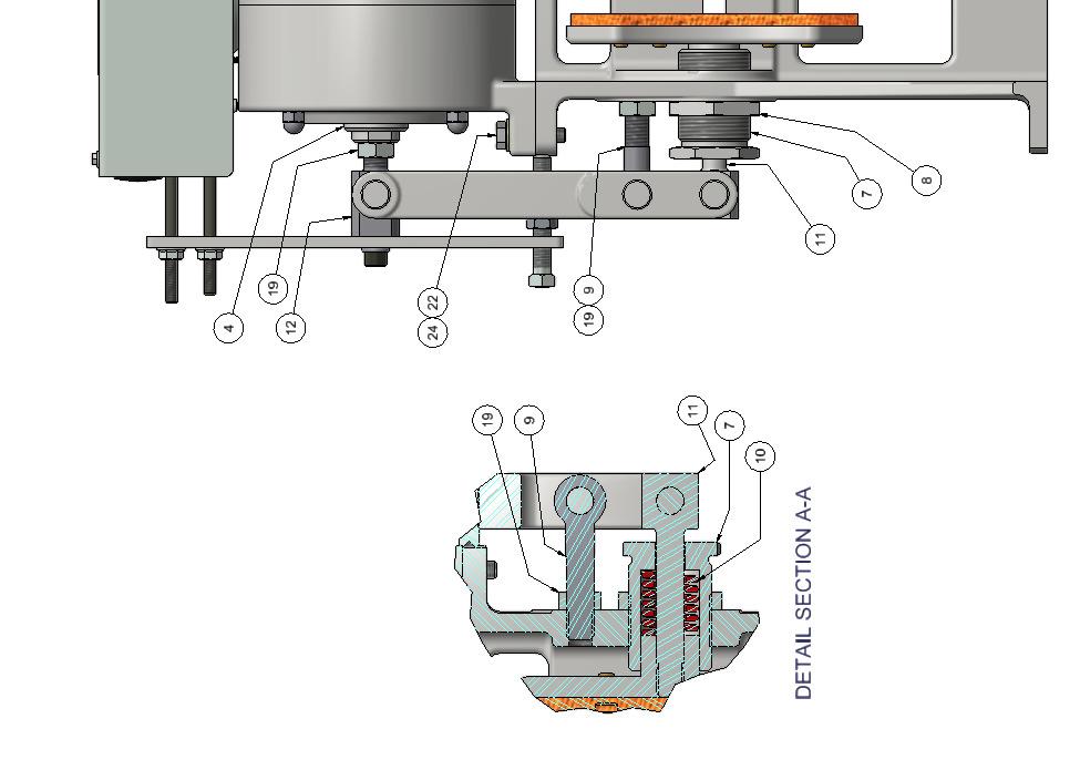
4 NOTE: ALL INITIAL ADJUSTMENTS SHOULD BE DONE WITH EMPTY CAR IN OVERHEAD AND THE COUNTERWEIGHT LANDED A D J U S T M E N T S: 1.) SPRING ADJUSTMENT: With Brake applied (Coil de-energized), adjust spring pressure by loosening Lock Nut (A) and screwing Spring Housing (B) into Brake Housing. Note clearance (C), between Brake Shoe (D) and Spring Housing must be equal on both sides and enough for Brake Shoe to pick up when coil is energized. Initially, adjust clearance (C) to 1/8" and tighten Lock Nut (A). (Note: This may not be the final setting for 125% load. When finally set at 125% load, the spring pressure may be less than above. Check to see that Brake stops 100% load at approximately the slow-down rate.) 2.) CENTERING SCREW INITIAL ADJUSTMENT: With Brake applied, adjust Centering Screws (E) until they are 1/4 away from the Brake Housing. 3.) BRAKE ARM ADJUSTMENT: With Brake applied, check that Brake Arms (F) are vertically parallel or angled slightly in toward the Solenoid Housing. If adjustment is necessary, remove Snap Rings and Pins (G) [3 per side]. Arms (F) can now be lifted out of the way. Adjust Pivot Eye-bolt (Q) for proper alignment. When aligned, grease Pins, re-assemble Pins, and re-tighten Lock Nut (P). 4.) BRAKE COIL VOLTAGE ADJUSTMENT: To set the Brake Coil voltage, momentarily energize the Brake. Set the Brake Coil voltage per the following: 230V Coil 115V Coil If voltage is constant: 230V 115V If dual voltage: 250V Pick Up 125V Pick Up 150V Hold 75V Hold PICK UP voltage should be applied long enough to ensure Solenoid Plungers are touching before dropping to the HOLD voltage. On controls that require a voltage calibration, be sure to adjust calibration. Please note: Coil may lose 30% of power when hot! 5.) BRAKE SHOE GAP ADJUSTMENT: With Brake energized, set gap between the Shoes (D) and the Disc (L) of 0.012". With Brake applied (Coil de-energized), loosen Lock Nut (M) and adjust Solenoid Plungers (N) so that an equal amount of each Plunger shows on each side of the Solenoid Housing. Energize Brake, check the 0.012" gap, re-adjust as necessary. NOTES: Page 4 of 11
5 a.) b.) c.) d.) Moving the Plungers out produces a larger gap between the Shoes and Disc when the Brake Coil is energized. If a Shoe is not parallel to the Disc when the Coil is energized, it may be necessary to tap Pivot Bolt (Q) up or down to affect the parallel gap. If one shoe picks up slower than the other, loosen the spring on that side while tightening the spring on the other side an equal amount. When installing a NEW Brake on an EXISTING MACHINE, it may be necessary to shim the Brake Housing to achieve Shoe-to-Disc parallelism if Shoes are parallel with each other but not with the Disc. 6.) CENTERING SCREW FINAL ADJUSTMENT: With Coil energized, adjust each Centering Screw (E) to just touch Brake Housing, then adjust each Centering Screw out one quarter turn, and tighten Lock Nut. 7.) SEE BRAKE MONITOR SWITCH ADJUSTMENTS. 8.) Run elevator as much as possible to assure proper operation. 9.) CAUTION: Before releasing car to the public, re-check that Brake is operating properly and will stop 125% load. If Brake Tension is ever changed, re-adjust Items 5.), 6.), and 7.) above. Page 5 of 11

6 BRAKE MONITOR SCHEMATIC AND WORKING PROCEDURE: WARNING: IN ORDER TO DETECT A BRAKE FAILURE, THIS BRAKE MONITOR SWITCH MUST BE PROPERLY ADJUSTED & FULLY OPERATIONAL PRIOR TO BEING PLACED INTO SERVICE. IMPORTANT: READ ENTIRE INSTRUCTIONS BEFORE ATTEMPTING ADJUSTMENT!!! SHOCK WARNING: A C T I V E E L E C T R I C C I R C U I T S!! BRAKE MONITOR ADJUSTMENT: 1. Adjust top bolt in until you hear micro switch click. 2. Rotate top bolt in 1 full revolution then tighten jamb nut against extension arm. 3. Adjust bottom bolt in until you hear micro switch click. 4. Rotate bottom bolt out until you hear micro switch click 5. Rotate bottom bolt out 1 full revolution then tighten jamb nut against extension arm. 6. Repeat steps 1 thru 5 on opposite side of monitor. 7. Cycle Brake check for micro switch activation and circuits are performing as designed. 8. Run machine and check adjustment when machine is at operating temperature. 9. Fine tuning may be needed per bolt until proper adjustment is obtained. Page 6 of 11
 If both contacts A & D fail to open with Brake energized, failure indicates improper pick up which can cause lining wear.")
. b.")
7 BRAKE FAILURE: DO NOT RE-ADJUST THE BRAKE MONITOR SWITCH UNTIL THE BRAKE PROBLEM HAS BEEN CORRECTED AND THE BRAKE RE-ADJUSTED. a.) If both contacts A & D fail to open with Brake energized, failure indicates improper pick up which can cause lining wear. Re-check Brake voltages, air gaps, alignment and freedom of arm and plunger movement, etc. To test this failure, place a jumper across terminals BM1 & BM2. The controls should remove the elevator from service in some fashion (See Suggested Operation on Page #8). b.) If contact A or D stays opened when Brake drops, failure indicates improper drop out caused by a bind (find bind and correct) or by excessive worm shaft movement (check thrust bearings etc.). To test, hold open contacts A or D, when elevator stops it should not be able to start (See Suggested Operation on Page #8). c.) If contacts B or C open when Brake drops, this indicates either worm shaft movement (check thrust bearings, etc.) or brake lining wear. If cause is normal lining wear, re-adjust Brake including spring tension, air gap, and centering screws, then re-adjust Brake Monitor Switch. To test open contacts B or C. Elevator should not be able to start (See Suggested Operation on Page #8). NOTE: BRAKES MUST BE INSPECTED DURING NORMAL ELEVATOR MAINTENANCE. IF LININGS INDICATE WEAR, THEN SPRINGS, GAPS AND MONITOR SWITCH MUST BE RE- ADJUSTED ACCORDINGLY. FOR EXAMPLE: IF LININGS WEAR 1/32", TURNING THE SPRING HOUSING EYEBOLT OUT ONE- HALF (1/2) TURN AND TIGHTENING THE SPRING HOUSING IN ONE-THIRD (1/3) TURN WILL COMPENSATE. PLUNGERS AND THE BRAKE MONITOR WILL NEED TO BE SLIGHTLY RE- ADJUSTED. ANY ADJUSTMENT MADE TO THE BRAKE MIGHT AFFECT BRAKE MONITOR ADJUSTMENT. Page 7 of 11
8 SUGGESTED OPERATION OF ELEVATOR CONTROLS USED WITH THE HOLLISTER-WHITNEY MACHINE BRAKE MONITOR NOTE: These are only suggested modes of operation. HOLLISTER-WHITNEY recognizes that each controls manufacturer may have their own circuits and problems designed to deal with potential Brake failures. It is important that Brake failures be dealt with in some fashion. NORMAL OPERATION 1.) With the Machine brake de-energized, contacts A thru D are made. Continuity is read from terminals BM1 and BM2. ACTION: Control circuits and program allow elevator to run. 2.) When the elevator runs, the Machine Brake energizes and contacts A & D open. An open circuit is read from terminals BM1 and BM2. ACTION: Control circuits and programs allow the elevator to continue normal operation. ABNORMAL OPERATION 1.) After energizing the Brake, check for continuity between BM1 and BM2. If continuity is still read from terminals BM1 to BM2 (all of the contacts A thru D are made), this indicates that the Machine Brake has failed to pick up. ACTION: Allow the car to run to the next floor. Control circuits and programs should remove the car from service. Apply the ROPE GRIPPER. 2.) After de-energizing the Brake, check for continuity between BM1 and BM2. If continuity is not read from BM1 to BM2 it indicates improper drop-out of the Machine Brake, Brake Lining wear, or excessive Worm Shaft movement. ACTION: Apply the ROPE GRIPPER. If a ROPE GRIPPER is not available, prevent the car from running. If re-leveling occurs - see below. 3.) A constant re-leveling may indicate a Brake failure. ACTION: Apply ROPE GRIPPER. If a ROPE GRIPPER is not available, allow re-leveling at the floor, run the car to the uppermost floor, open the door during re-leveling, close the doors, and remove the car from service. Page 8 of 11

9 Page 9 of 11
10 Coils for #92 Disc Brake PARTS LIST - DISC BRAKE NO. DESCRIPTION QTY. 92 BRAKE (10" DISC) PART NUMBER 1 DISC BRAKE HOUSING DISC BRAKE LEVER PLUNGER - DISC BRAKE PLUNGER w/ring - DISC BRAKE SOLENOID HOUSING ASSEMBLY - 230V COIL SOLENOID HOUSING ASSEMBLY - 115V COIL DISC BRAKE SHOE ASSEMBLY SPRING HOUSING NUT - SPRING HOUSING PIVOT EYEBOLT SPRING EYEBOLT - SPRING HOUSING EYEBOLT - SLOTTED PLUNGER SHOULDER BOLT BUSHING BRAKE MONITOR ASSEMBLY BRAKE ARM EXTENSION PIN - PIVOT ARM E-RING, NUT - HEX JAM 4 1/2-13 UNC 20 SQUARE HEAD SET SCREW 2 3/8-16 UNC X HEX JAM NUT 2 3/8-16 UNC 22 HEX HEAD CAP SCREW 4 5/16 UNC x SOCKET HEAD CAP SCREW 2 5/16-18 UNC x STANDARD WASHER 4 5/16" WASHER 25 STANDARD LOCK WASHER 2 5/16 WASHER 26 SOCKET HEAD CAP SCREW 4 1/4-20 UNC X WHIZ NUT 4 1/4-20 UNC 28 SOCKET HEAD CAP SCREW 2 #10-24 UNC x STANDARD LOCK WASHER 2 #10 LOCK WASHER 1) Coil (Part # ) 1.66 A, 138 OHM - Constant 230 VDC, or Step Down 250 V Pick, 150 V Hold 2) Coil (Part # ) 3.48 A, 33 OHM - Constant 115 VDC, or Step Down 125 V Pick, 75 V Hold Page 10 of 11

11 Notes Procedures Date Initials Reference documentation can be found at Page 11 of 11
DRUM BRAKE ADJUSTMENTS, MODELS #90, #100, #110 & #120 # BRAKE MONITOR
 DRUM BRAKE ADJUSTMENTS, MODELS #90, #100, #110 & #120 #102-092 BRAKE MONITOR Page 1 of 7 HOLLISTER-WHITNEY DRUM BRAKE WITH MONITOR ADJUSTMENTS IMPORTANT: READ ENTIRE INSTRUCTIONS BEFORE ATTEMPTING ADJUSTMENT!!!
Hollister-Whitney Elevator Corporation
 Hollister-Whitney Elevator Corporation Installation and Service Manual GL101, GL131, GL171, GL130A, GL185 and GL260 AC Permanent Magnet, Gearless Machines Page 1 of 32 Table of Contents I. Introduction
INSTALLATION INSTRUCTIONS AMBASSADOR DRUM OVERHEAD SERIES 100 DUMBWAITER
 INSTALLATION INSTRUCTIONS AMBASSADOR DRUM OVERHEAD SERIES 100 DUMBWAITER The installation of Matot Drum Dumbwaiters should only be performed by qualified, experienced, and trained elevator installers.
Tooling Assistance Center
 Safeguards are designed into this application equipment to protect operators and maintenance personnel from most hazards during equipment operation. However, certain safety precautions must be taken by
Installation Guide VHM Arm Kit for Philips Heartstart MRx and Heartstart XL+
 Installation Guide VHM Arm Kit for Philips Heartstart MRx and Heartstart XL+ The purpose of this guide is to: 1. Describe installation of Arm in channel (page 2). 2. Describe mounting of defibrillator
Synchronous Wired and Electronic Movement Manual
 Synchronous Wired and Electronic Movement Manual Hanson Movement General Synchronous-wired and electronic secondaries are controlled by a Hansen movement. Except for a short correction cycle each hour,
Handy Lift HD Owners Manual WARNING. BURR 500 lb. Capacity Handy Lift HD PN (40 ) PN (45 ) PN (50 )
 PN (45 ) PN (50 )") Installation and Operating Instructions - Service and Parts Information BURR 500 lb. Capacity Handy Lift HD PN 32689 (40 ) PN 33145 (45 ) PN 33056 (50 ) Avoid serious injury, or death, to yourself and
Installation and Operating Instructions - Service and Parts Information BURR 500 lb. Capacity Handy Lift HD PN 32689 (40 ) PN 33145 (45 ) PN 33056 (50 ) Avoid serious injury, or death, to yourself and
Optimal Series. Automatic Transfer Switch. Installation and User Manual for the OPT2225 Automatic Transfer Switch. Full Version
 Optimal Series Automatic Transfer Switch Installation and User Manual for the OPT2225 Automatic Transfer Switch Full Version File: OPT2225 Rev2.5.doc November, 2004 2 Thank You For Purchasing This DynaGen
Installation Guide VHM Wall Mount Kit for Philips MX600/700/800 and MP60/70 IntelliVue
 Installation Guide VHM Wall Mount Kit for Philips MX600/700/800 and MP60/70 IntelliVue The purpose of this guide is to: 1. Describe attachment of Table Top Mount to Mounting Adapter (page 2). 2. Describe
MiTek Machinery Division. Service Bulletin
 MiTek Machinery Division Service Bulletin Machinery Affected: Document: Title: Applies To: Distribution: RoofGlider Press SB198 Redesigned Push Bar Push Bars Manufactured With Gas Spring and Clamp-Style
INSTALLATION & OWNER S MANUAL
 Rev. A, p. 1 of 13 INSTALLATION & OWNER S MANUAL Polaris Ranger (2009-) Straight UTV Steel Plow with Vehicle Mount Kit 6 Wide Snow Plow (p/n: 1POLSP) (fits the 500 H.O., 700 & 800 HD & XP) The contents
GLACIER PRO RANGER MID SIZE MOUNT KIT
 GLACIER PRO RANGER MID SIZE MOUNT KIT P/N 2880261 APPLICATION FOR USE WITH THE GLACIER PRO MID SIZE PLOW SYSTEM (P/N 2880260) ON 2010 AND NEWER RANGER MID SIZE MODELS BEFORE YOU BEGIN Read these instructions
I-317. AWWA Check Valves WARNING INSTALLATION AND MAINTENANCE INSTRUCTIONS SERIES 317 WARNING
 Read and understand all instructions before attempting to install, remove, adjust, or perform maintenance on any Victaulic piping products Wear safety glasses, hardhat, and foot protection. Failure to
Technical Support (707)
") Installation Instructions UNIMATIC SHIFTER Fits: GM, Powerglide, Ford and Chrysler Transmissions See Application Guide for Specific Vehicles Catalog # 80775 WORK SAFELY! For maximum safety, perform this
Installation Instructions UNIMATIC SHIFTER Fits: GM, Powerglide, Ford and Chrysler Transmissions See Application Guide for Specific Vehicles Catalog # 80775 WORK SAFELY! For maximum safety, perform this
Contents. Section 5: Adjustments Ball Detect Adjustment Transport Band Tension Adjustment
 Contents Section 5: Adjustments... 5-3 1. Ball Detect Adjustment... 5-3 2. Transport Band Tension Adjustment... 5-5 3. Transport Band Drive Belt Tension Adjustment... 5-7 4. Ball Cushion Adjustment...
20. Install and tighten the cap screws that hold the end frame and field frame together
 4006-30 19. Fill the oil reservoir in the bearing bore of the end frame with SAE 10 engine oil. Then put the the end frame on the armature shaft. Align the marks on the end frame and field frame and push
Serial Number Range. Jib-Hoist. from SN Part No
 Serial Number Range Jib-Hoist from SN 56306 Part No. 645045 Rev B May 2010 2 Jib-Hoist Part No. 645045 How to Read Your Serial Number Part No. 645045 Jib-Hoist 3 Table of Contents This manual is updated
INSTALLATION OF HOTCHKIS PERFORMANCE DOUBLE ADJUSTABLE TRAILING ARMS
 1215 DOUBLE ADJUSTABLE UPPER TRAILING ARMS 67-70 CHEVROLET B-BODY This installation will require: A hydraulic jack, jack stands The following wrenches or sockets: 15/16 Adjustable wrench (1-1/4 1-9/32
VHM-P (Non-Locking) and VHM-PL (Locking) Variable Height Arm with Slide-In Mounting Plate
 and VHM-PL (Locking) Variable Height Arm with Slide-In Mounting Plate") 3875 Cypress Drive Petaluma, CA 94954 800.228.2555 +1.707.773.1100 Fax 707.773.1180 www.gcx.com VHM-P (Non-Locking) and VHM-PL (Locking) Variable Height Arm with Slide-In Mounting Plate (Refer to qualified
3875 Cypress Drive Petaluma, CA 94954 800.228.2555 +1.707.773.1100 Fax 707.773.1180 www.gcx.com VHM-P (Non-Locking) and VHM-PL (Locking) Variable Height Arm with Slide-In Mounting Plate (Refer to qualified
Caution Improper installation could result in tape failure, mounting hardware, and reader. Please read instructions before installing!
 Elgo Sensor Mounting Motion High Speed Landing/Positioning System The encoded tape used for the landing system is suspended between two mounting brackets that attach to the car rail using forged clips
DISASSEMBLY We suggest the vehicle be allowed to cool for an hour or two before you begin since you will be working around the exhaust system.
 Installation Instructions Short Throw Shifter Fits: 1984-2006 BMW 3 Series E30, E36 & E46 1987-2006 BMW 3 Series M3 & 1996-2002 BMW 5 Series Catalog # 45126 WORK SAFELY! For maximum safety, perform this
Installation Instructions Unimatic Shifter
 Installation Instructions Unimatic Shifter Universal Shifter for Automatic Transmissions Part Number 80775 2010, 2000 by B&M Racing & Performance Products The B&M Unimatic is a universal shifter that will
Installation Instructions Capacity 10,000 lbs. (100 Series Lift)
") Installation Instructions Capacity 10,000 lbs. (100 Series Lift) IMPORTANT Reference ANSI/ALI ALIS, Safety Requirements for Installation and Service of Automotive Lifts before installing lift. OPERATING
Installation Instructions Capacity 10,000 lbs. (100 Series Lift) IMPORTANT Reference ANSI/ALI ALIS, Safety Requirements for Installation and Service of Automotive Lifts before installing lift. OPERATING
ELECTRICAL. Contents - Wiring Diagrams
 Contents - Wiring Diagrams T-Bar (Floating Deck - Hydro)............................................ 8-16 T-Bar (Fixed Deck - Gear)............................................... 8-17 T-Bar (Fixed Deck
20Ja through 100Ja 9020Ja through 9070Ja Balancer Series Service Manual
 AERO-MOTIVE COMPANY A Woodhead Industries, Inc. Subsidiary 20Ja through 00Ja 9020Ja through 9070Ja Balancer Series Service Manual IMPORTANT SAFETY INSTRUCTIONS Please read this manual carefully and follow
TRANSMISSION AND TRANSFER CASE
 DR TRANSMISSION AND TRANSFER CASE 21-1 TRANSMISSION AND TRANSFER CASE TABLE OF CONTENTS page MANUAL TRANSMISSION- G56- SERVICE INFORMATION...1 MANUAL TRANSMISSION- GETRAG 238- SERVICEINFORMATION...69 MANUAL
632 Western Avenue Henniker, New Hampshire Tel. (603) Fax (603) POSITION OF THE ROLLER PLATES
 Fax (603) POSITION OF THE ROLLER PLATES") POSITION OF THE ROLLER PLATES The roller plate must be positioned as shown. The measurement to both of the roller plates is taken from the face of the kingpin shaft to the inside edge of the roller wheel
POSITION OF THE ROLLER PLATES The roller plate must be positioned as shown. The measurement to both of the roller plates is taken from the face of the kingpin shaft to the inside edge of the roller wheel
Assembly & Installation Instructions
 TM P R O D U C T S Assembly & Installation Instructions FOR 28 SERIES SNOWPLOW PIVOT ASSEMBLY AND FLOAT LIMITER 99103000 FOR SERIAL NUMBERS 28D100000 TO 28D100770 97100552A 1. THINK SAFETY, ALWAYS WEAR
BALDOR MN413 Brakes Manual
 BALDOR MN413 Brakes Manual http://www.manuallib.com/baldor/mn413-brakes-manual.html The DODGE D-Series motor brakes are manufactured to NEMA standards for mounting to C-face and double shafted motors.
Installation Instructions Unimatic Shifter
 Installation Instructions Unimatic Shifter Universal Shifter for Automatic Transmissions Part Number 80775 2000 by B&M Racing & Performance Products LLC The B&M Unimatic is a universal shifter that will
Installation Manual For ISL98, ISL03, ISL07, ISC07
 Installation Manual For ISL98, ISL03, ISL07, ISC07 Table of Contents Section 1: Introduction... 3 Housing Identification... 3 Engine Identification... 3 Special Tools... 3 Automatic Transmissions... 3
110KA through 200KA & 9110KA through 9150KA Balancer Series Service Manual
 AERO-MOTIVE COMPANY A Woodhead Industries, Inc. Subsidiary 0KA through 200KA & 90KA through 950KA Balancer Series Service Manual IMPORTANT SAFETY INSTRUCTIONS Please read this manual carefully and follow
OPERATIONS/PARTS MANUAL FOR PATTERSON'S WWP40E P-L/R ELECTRIC WINCH.
 DOC # A0000298 / A0000299 Patterson Company 870 Riversea Road Pittsburgh, PA 15233 Phone: 800-322-2018 FAX: 412-322-2785 OPERATIONS/PARTS MANUAL FOR PATTERSON'S WWP40E-7.5-14-208-P-L/R ELECTRIC WINCH.
NOTE: Skids, springs, center section, and hardware are located in the push tube box.
 72 HYDRAULIC V-PLOW MOUNTING INSTRUCTIONS BLADE P/N: 4501-0190 PUSH TUBE ASSM P/N: 4501-0191 CUSTOMER MUST RECEIVE A COPY OF THIS INSTRUCTION SHEET AT THE TIME OF SALE NOTE: Skids, springs, center section,
TC35160 & TC35270 Operation Manual & Installation Instructions
 Please visit www.blueox.com for the latest version of these installation instructions. TC35160 & TC35270 Operation Manual & Installation Instructions Serial Number Blue OX One Year Limited Warranty 292-6090
MODEL HD-P10000 PLANETARY WINCH
 OPERATING, SERVICE AND MAINTENANCE MANUAL MODEL HD-P10000 PLANETARY WINCH CAUTION: READ AND UNDERSTAND THIS MANUAL BEFORE INSTALLATION AND OPERATION OF WINCH. SEE WARNINGS! TABLE OF CONTENTS INTRODUCTIONS................................................................1
This file is available for free download at
 This file is available for free download at http://www.iluvmyrx7.com This file is fully text-searchable select Edit and Find and type in what you re looking for. This file is intended more for online viewing
SERIES A & AA ROLLER DOORS INSTALLATION GUIDE
 SERIES A & AA ROLLER DOORS INSTALLATION GUIDE THESE INSTRUCTIONS ARE PROVIDED FOR USE BY EXPERIENCED INSTALLERS OF GARAGE DOORS BY UNDER-TAKING THE INSTALLATION OF THIS DOOR, THE INSTALLER UNDERSTANDS
OPERATIONS/PARTS MANUAL FOR PATTERSON'S MODEL # WWP65E ELECTRIC WINCH.
 DOC # 5251-F W. W. Patterson Company 3 Riversea Road Pittsburgh, PA 15233 Phone: 800-322-2018 FAX: 412-322-2785 OPERATIONS/PARTS MANUAL FOR PATTERSON'S MODEL # WWP65E-7.5-14 ELECTRIC WINCH. Please fill
Maintenance Information
 Form 16575334 Edition 1 April 2005 Electric Screwdrivers EL, EP and ET 34V DC Series Maintenance Information Save These Instructions WARNING Maintenance procedures have the potential for severe shock hazard
SERIES B & C ROLLER DOORS INSTALLATION GUIDE
 SERIES B & C ROLLER DOORS INSTALLATION GUIDE THESE INSTRUCTIONS ARE PROVIDED FOR USE BY EXPERIENCED INSTALLERS OF GARAGE DOORS BY UNDERTAKING THE INSTALLATION OF THIS DOOR, THE INSTALLER UNDERSTANDS THE
./#0#. 1"&." 1994 ELECTRICAL Suzuki of America Corp. - Starters. Swift
 !"" #$%!& '()!)((*(+,*)- 1994 ELECTRICAL Suzuki of America Corp. - Starters Swift Two types of starter motors are used, conventional and reduction gear. Both types of starters consist of yoke assembly,
Installation Guide. Philips MP20/30/40/50 IntelliVue VHM Wall Mount Kit
 Installation Guide Philips MP20/30/40/50 IntelliVue VHM Wall Mount Kit The purpose of this guide is to: 1. Describe attachment of Table Top Mount to Mounting Adapter. 2. Describe attachment of Mounting
LIGHT DUTY ROLL UP DOOR
 1-800-225-6729 LIGHT DUTY ROLL UP DOOR CAUTION Use proper lifting equipment and correct lifting procedures to avoid damage or injury. MODEL 150C installation guide A rolling door is a large heavy object
Model MC-35 Impact Press. Operation & Maintenance Instructions
 Model MC-35 Impact Press Operation & Maintenance Instructions Revised 12/05/2007 WARNINGS 1. Safety glasses must always be worn by the machine operator, as well as any co-workers, or any other persons
PAGE 1. 7/18 HJ26141 Rev 12
 PAGE 1 7/18 HJ26141 Rev 12 WARRANTY POLICY, OPERATOR MANUALS & REGISTRATION Go online to www.demco-products.com to review Demco warranty policies, operator manuals and register your Demco product. Please
I-VIC300MS. Vic -300 MasterSeal Butterfly Valves WARNING SERIES 761
 warning Read and understand all instructions before attempting to install, remove, adjust, or perform maintenance on any Victaulic piping products. Depressurize and drain piping systems before attempting
470 Frame Synchronous AC Permanent Magnet Gearless Motors
 470 Frame Synchronous AC Permanent Magnet Gearless Motors AC Gearless Machines Imperial Alternating Current, Permanent Magnet, Gearless Machines are available in three frame sizes to suit a wide range
INSTALLATION INSTRUCTIONS
 INSTALLATION INSTRUCTIONS --1075 North Ave. Sanger, CA 93657-3539 local: 559-875-0222 fax: 559-876-2259 toll free: 800-445-3767-- 2505 Lowering Spindle Assembly Installation Instructions ½ TON SILVERADO
BX7322 Adventurer Tow Bar Operator Manual & Installation Instructions. (5,000 lb) 2 Inch Coupler
 2 Inch Coupler") Operator Manual & Installation Instructions (5,000 lb) 2 Inch Coupler General Information DO NOT INSTALL, OPERATE OR USE THIS EQUIPMENT UNTIL THE FOLLOWING OPERATING AND SAFETY INSTRUCTIONS HAVE BEEN READ
Operator Manual & Installation Instructions (5,000 lb) 2 Inch Coupler General Information DO NOT INSTALL, OPERATE OR USE THIS EQUIPMENT UNTIL THE FOLLOWING OPERATING AND SAFETY INSTRUCTIONS HAVE BEEN READ
Fisher 657 Diaphragm Actuator Sizes and 87
 Instruction Manual 657 Actuator (30-70 and 87) Fisher 657 Diaphragm Actuator Sizes 30 70 and 87 Contents Introduction... 1 Scope of Manual... 1 Description... 2 Specifications... 2 Installation... 3 Mounting
70 Series 8700 End Mount Three Phase Brake Instructions IP43 (NEMA 2) Housing
 Housing") Bulletin No. BK4772S-3 (6/2017) 70 Series 8700 End Mount Three Phase Brake Instructions IP43 (NEMA 2) Housing Read carefully before attempting to assemble, install, operate or maintain the product described.
Bulletin No. BK4772S-3 (6/2017) 70 Series 8700 End Mount Three Phase Brake Instructions IP43 (NEMA 2) Housing Read carefully before attempting to assemble, install, operate or maintain the product described.
Service Jacks. Operating Instructions & Parts Manual. Model Number. Capacity 4 Ton 4 Ton Air/ Manual 10 Ton 10 Ton Air/ Manual HW93657/ HW93660
 Service Jacks Operating Instructions & Parts Manual Model Number HW93657 HW93667 HW93660 HW93662 Capacity 4 Ton 4 Ton Air/ Manual 10 Ton 10 Ton Air/ Manual Made in North America HW93657/ HW93660 HW93667/
Bag 1. Bag 1. Center Pivot. Center Pivot
 8 00734 01901 5 Center Pivot Bag 1 3374 - Center Pivot Socket 4019 - Alum Pivot ball 3254-2-56 Button Head *Note - Sometimes it is helpful to slightly over-tighten the top clamp screws, then work the ball
C. Figure 1. CA-16 Front View Figure 2. CA-16 Rear View
 Figure 1. CA-16 Front View Figure 2. CA-16 Rear View 2 2.1. Restraint Elements Each restraint element consists of an E laminated electromagnet with two primary coils and a secondary coil on its center
Fisher 3024C Diaphragm Actuator
 Instruction Manual 3024C Actuator Fisher 3024C Diaphragm Actuator Contents Introduction... 1 Scope of Manual... 1 Description... 2 Specifications... 3 Installation... 5 Mounting the Actuator on the Valve...
Instruction Sheet. 22 Inch Reels. 18 Inch Reels. 11 Blade L.H G-Plex, E-Plex Eclipse Eclipse 122F
 6 9 6 7 7 - INCLUDES ITEMS - 6 9 0 0000-Rev E Instruction Sheet Inch Reels Blade L.H. 67 - G-Plex, E-Plex 60 - Eclipse 60 - Eclipse F 9 Blade L.H. 676 - G-Plex, E-Plex 607 - Eclipse 7 Blade L.H. 677 -
SL-6 & SL-6A. I UNION SWITCH & SIGNAL l[ml 645 Russell Street Batesburg, SC Service Manual Field and Shop Maintenance
 I UNION SWITCH & SIGNAL l[ml 645 Russell Street Batesburg, SC 29006 Service Manual 3011 SL-6 & SL-6A Outlying Switch Lock Field and Shop Maintenance April, 1979 A-79-500-1496-3 1979, Union Switch & Signal
ProTrip Conversion Kits. For GE Types AK-15, AK-25, and AKU- 25 Low-Voltage Power Circuit Breakers INTRODUCTION. DEH Installation Instructions
 DEH 40026 Installation Instructions g ProTrip Conversion Kits For GE Types AK-15, AK-25, and AKU- 25 Low-Voltage Power Circuit Breakers INTRODUCTION GE Conversion Kits are designed for upgrading existing
Handy Lift LT Owners Manual
 Installation and Operating Instructions - Service and Parts Information BURR 300 lb. Capacity Handy Lift LT PN 33170 (40 ) PN 33171 (45 ) PN 33172 (50 ) Avoid serious injury, or death, to yourself and
GLACIER PRO PLOW FRAME KIT
 GLACIER PRO PLOW FRAME KIT P/N 2883255 APPLICATION All 2009 and newer RANGER XP Full installation of the Glacier Pro plow system requires a winch with an auto-stop fairlead and a synthetic winch rope or
Installation Instructions
 Installation Instructions 2-Post Capacity 12,000 lbs. OPERATING CONDITIONS Lift is not intended for outdoor use and has an operating ambient temperature range of 41-104 F (5-40 C) IMPORTANT Reference ANSI/ALI
Model Torque Multiplier
 Model 8111-8112 Torque Multiplier OPERATING INSTRUCTIONS Page 1 of 6, REV. B The Sweeney 8111 and 8112 Torque Multipliers provide maximum power for breakaway and maximum speed for run-off of large threaded
K Autoslide & K Autoslide
 HJ26077, Rev 16 07/18 5th wheel hitch 6077 18K Autoslide & 6107 21K Autoslide US Pat. 7,506,886 US Pat. 7,753,392 CA Pat. 2,576,427 AS Pat. 2007200421 Important Information WARRANTY POLICY, OPERATOR MANUALS
MODEL RPH 15,000 PLANETARY WINCH
 OPERATING, SERVICE AND MAINTENANCE MANUAL MODEL RPH 15,000 PLANETARY WINCH CAUTION: READ AND UNDERSTAND THIS MANUAL BEFORE INSTALLATION AND OPERATION OF WINCH. SEE SAFEGUARDS AND WARNINGS! TABLE OF CONTENTS
Installation Instructions Capacity 10,000 lbs. DP10 (200 Series Lift)
") Installation Instructions Capacity 10,000 lbs. DP10 (200 Series Lift) IMPORTANT Reference ANSI/ALI ALIS, Safety Requirements for Installation and Service of Automotive Lifts before installing lift. OPERATING
Installation Instructions Capacity 10,000 lbs. DP10 (200 Series Lift) IMPORTANT Reference ANSI/ALI ALIS, Safety Requirements for Installation and Service of Automotive Lifts before installing lift. OPERATING
Installation, Operating & Maintenance Instructions
 Electromechanical Linear Actuators Installation, Operating & Maintenance Instructions with parts list TAC Models with Clutch TAL Models with Limit Switches TAC Models with Limit Switches and Potentiometer
IMPORTANT: If you are experiencing slider issues, it may be due to a period of inactivity and an accumulation of debris in the mechanism.
 IMPORTANT: If you are experiencing slider issues, it may be due to a period of inactivity and an accumulation of debris in the mechanism. Corrosion of vehicle components due to over exposure to very corrosive
Premium wheel-end brake products
 Premium wheel-end brake products Spicer Automatic Slack Adjuster Service Manual Self Adjusting Brake Adjuster The description and specifications contained in this service publication are current at the
COYOTE ENTERPRISES, INC. 9/10 BLAST WHEEL MAINTENANCE & ASSEMBLY MANUAL
 COYOTE ENTERPRISES, INC. 9/10 BLAST WHEEL MAINTENANCE & ASSEMBLY MANUAL Parts & Machinery for the Abrasive Blast Industry 27301 East 121st Street Coweta, Oklahoma 74429 (918) 486-8411 Fax (918) 486-8412
Model 2300DL Installation Guide
 Model 2300DL Installation Guide POWER ACCESS CORPORATION 4 HERSHEY DRIVE, DOCK 4 ANSONIA, CT 06401 800-344-0088 WEBSITE: www.power-access.com EMAIL: salesinfo@power-access.com 1 STANDARD PARTS MODEL 2300DL
GD-1 / GD-2 Sheave Brake
 GD-1 / GD-2 Sheave Brake Every attempt has been made to ensure that this documentation is as accurate and up-to-date as possible. However, Vertical Express assumes no liability for consequences, directly
70 Series 8700 End Mount Three Phase Brake Instructions IP56 (NEMA 4) Housing
 Housing") Bulletin No. BK4773-3 (08/2016) 70 Series 8700 End Mount Three Phase Brake Instructions IP56 (NEMA 4) Housing Read carefully before attempting to assemble, install, operate or maintain the product described.
Bulletin No. BK4773-3 (08/2016) 70 Series 8700 End Mount Three Phase Brake Instructions IP56 (NEMA 4) Housing Read carefully before attempting to assemble, install, operate or maintain the product described.
IMPORTANT: If you are experiencing slider issues, it may be due to a period of inactivity and an accumulation of debris in the mechanism.
 IMPORTANT: If you are experiencing slider issues, it may be due to a period of inactivity and an accumulation of debris in the mechanism. Corrosion of vehicle components due to over exposure to very corrosive
Installation Information 2009 Model 300 Dumbwaiter
 Installation Information 2009 Model 300 Dumbwaiter 3/17/09 Introduction This new model of Matot Dumbwaiter has several features that we hope you find are beneficial. Precision extruded rail sections provide
7/18 HJ26077 Rev 16. US Pat. 7,506,886 US Pat. 7,753,392 CA Pat. 2,576,427 AS Pat PAGE 1
 7/18 HJ26077 Rev 16 US Pat. 7,506,886 US Pat. 7,753,392 CA Pat. 2,576,427 AS Pat. 2007200421 PAGE 1 WARRANTY POLICY, OPERATOR MANUALS & REGISTRATION Go online to www.demco-products.com to review Demco
Z-Gate Universal Shifter
 Installation Instructions Z-Gate Universal Shifter Fits: GM, Ford, Lincoln and Chrysler Transmissions See Application Guide for Specific Applications Part #80681 Rev 06/01/2018 WORK SAFELY! For maximum
INSTALLATION INSTRUCTIONS South Highway 11 Westminster, SC Toll Free (888) (864) FAX (864)
 (864) FAX (864)") 1.0 Purpose: To identify requirements for the replacement of ISS seals, o-ring and installation of gland nut to rod. 2.0 Scope: This instruction applies to the ISS units manufactured at Lift Technologies
1.0 Purpose: To identify requirements for the replacement of ISS seals, o-ring and installation of gland nut to rod. 2.0 Scope: This instruction applies to the ISS units manufactured at Lift Technologies
6/17 HJ26077 Rev 12. US Pat. 7,506,886 US Pat. 7,753,392 CA Pat. 2,576,427 AS Pat PAGE 1
 6/17 HJ26077 Rev 12 US Pat. 7,506,886 US Pat. 7,753,392 CA Pat. 2,576,427 AS Pat. 2007200421 PAGE 1 WARRANTY POLICY, OPERATOR MANUALS & REGISTRATION Go online to www.demco-products.com to review Demco
Installation Guide. Stowe Cargo Management System. Table of Contents
 Installation Guide Stowe Cargo Management System Table of Contents 1. Pre-Installation (Page 2) a. Notes, Installation Kit contents & Tools needed 2. How to Install the Stowe Cargo Management System (Pages
SwayPro. NOTE: A minimum tongue weight of 200 lbs. is required THANK YOU
 SwayPro Owner s Manual & Installation Instructions Serial Number Standard Hitch Head w/ Clamp-On Rotating Latches BXW0350 350 lbs. maximum tongue weight capacity BXW0550 550 lbs. maximum tongue weight
Spring-Engaged/Hydraulically-Released BD Caliper Brake. (i) MTY (81) QRO (442) MEX (55)
 MTY (81) QRO (442) MEX (55)") Spring-Engaged/Hydraulically-Released BD Caliper Brake (i) FORM NO. L-07-E-0300 In accordance with Nexen s established policy of constant product improvement, the specifications contained in this manual
Spring-Engaged/Hydraulically-Released BD Caliper Brake (i) FORM NO. L-07-E-0300 In accordance with Nexen s established policy of constant product improvement, the specifications contained in this manual
OLYMPIAN MODEL 740 Operation and Service Manual
 OLYMPIAN MODEL 740 Operation and Service Manual P/N 133911-102 FCI MANUAL P/N 133865-001 Data herein has been verified and validated and believed adequate for the intended use. If the machine or procedures
Lbs Kgs Ft M
 Installation Instructions for 92600 ATV Winch 3000 lb. Rated Pull SPECIFICATIONS Rated line pull: 3000 lbs. (1360kgs) single line Motor: Permanent magnetic DC 12V with 1.2 hp. /0.9kw output Gear: Differential
I-BFV.KIT Butterfly Valve Gear Operator Replacement
 SERIES 5, 05,, and 0C WARNING Read and understand all instructions before attempting to install, remove, adjust, or maintain any Victaulic piping products. Depressurize and drain the piping system before
CALIFORNIA TRIMMER MOWER MAINTENANCE MANUAL
 CALIFORNIA TRIMMER MOWER MAINTENANCE MANUAL 2 Table of Contents Section 1: General Information Page Handle Assembly Instructions 4 Maintenance All Models 6 Oil Change Procedures All Models 9 Height Adjustment
F O R M. Torq/Gard Installation, Operation and Maintenance Instructions. 8322E Revised March 2016 CAUTION WARNING
 Torq/Gard Installation, Operation and Maintenance Instructions Power Transmission Solutions Regal Beloit America, Inc. 7120 New Buffington Road Florence, KY 41042 Application Engineering: 800 626 2093
Reproduction or other use of this Manual, without the express written consent of Vulcan, is prohibited.
 SERVICE MANUAL ELECTRIC BRAISING PANS (30 & 40 GALLON) VE30 VE40 ML-126849 ML-126850 VE40 SHOWN - NOTICE - This Manual is prepared for the use of trained Vulcan Service Technicians and should not be used
Wheel Angle Sensor Kit Installation
 Wheel Angle Sensor Kit Installation Item Component Part Number Qty 1. Bracket Kit, WAS 200-0540-01 1 2. WAS Assembly 200-0468-01 1 3. Instruction Guide 602-0390-01 1 602-0390-01 REV A 2014-02 Overview
INSTRUCTIONS FOR OVERHAUL OF RAMEY RE SERIES WINCH
 INSTRUCTIONS FOR OVERHAUL OF RAMEY RE 12000 SERIES WINCH DISASSEMBLY 1. Drain oil from gear housing by removing plug # from bottom of gear housing. Remove relief fitting # and reducer # from top of gear
BX4330 Acclaim Tow Bar Operator Manual & Installation Instructions
 Operator Manual & Installation Instructions (5,000 lb) 2 Inch Coupler General Information DO NOT INSTALL, OPERATE OR USE THIS EQUIPMENT UNTIL THE FOLLOWING OPERATING AND SAFETY INSTRUCTIONS HAVE BEEN READ
Installation Instructions TH700-R4 (4L60) Transkit Part No thru 1986 Part No thru 1993 non-electronic models
 Transkit Part No thru 1986 Part No thru 1993 non-electronic models") Installation Instructions TH700-R4 (4L60) Transkit Part No. 70232 1982 thru 1986 Part No. 70233 1987 thru 1993 non-electronic models B&M Racing and Performance Products 2009 Congratulations! You have just
Installation Instructions TH700-R4 (4L60) Transkit Part No. 70232 1982 thru 1986 Part No. 70233 1987 thru 1993 non-electronic models B&M Racing and Performance Products 2009 Congratulations! You have just
S Voltage Regulators GENERAL. Contents. Acceptance and Initial Inspection. Handling and Storage. Standards
 Voltage Regulators QD8 Tap Changer Replacement Procedure Kit 57A63675100A Service Information S225-50-16 Contents General..................................... 1 Parts Supplied...1 Tools Required..............................
ALTRONIC, INC. 712 TRUMBULLAVE. GIRARD, OHIO DIS. IGNITION SYSTEM 500 SERIES IMPORTANT SAFETY NOTICE
 ALTRONIC D.I.S. MEDIUM ENGINES, 4-16 CYLINDERS SERVICE INSTRUCTIONS FORM DIS SI 6-91 ALTRONIC, INC. 712 TRUMBULLAVE. GIRARD, OHIO 44420 DIS. IGNITION SYSTEM 500 SERIES IMPORTANT SAFETY NOTICE PROPER INSTALLATION,
STARTER - HITACHI Isuzu Trooper II DESCRIPTION TESTING STARTER PERFORMANCE TESTS Starters HITACHI. Isuzu
 STARTER - HITACHI 1986 Trooper II 1984 Starters HITACHI DESCRIPTION Starter is a conventional 12-volt, 4-pole brush-type motor, with direct or reduction gear drive. The starter-mounted solenoid shifts
SIDI Camshaft Position Actuator Replacement
 BLOCK AND WEDGE TIMING CHAIN RETAINER USER GUIDE SIDI Camshaft Position Actuator Replacement Removal Procedure 1. Remove the camshaft cover. 2. Remove the camshaft position actuator solenoid valve solenoid
TIN KNOCKER FOURPLEX CLEAT FORMER INSTRUCTIONS & PARTS DIAGRAM
 TIN KNOCKER FOURPLEX CLEAT FORMER INSTRUCTIONS & PARTS DIAGRAM Sheet Metal Equipment Sales Inc. Dean P. O'Connell, President Green Bay, Wisconsin Phone - (90)-66-9966 Fax - (90)-66-9969 Website: www.sheetmetalequip.com
Product Description. Product Numbers. Warning/Caution Notations. Required Tools. Wiring. Prerequisites
 Document No. 155-302N VE 598 Electronic Flowrite Valve Field Assembly Product Description The VE 598 Electronic Valve Assemblies consist of an electronic actuator, linkage kit, and a valve body assembly.
70 Series 8700 Coupler 2-pc Hub & Shaft Three Phase Brake Instructions IP43 & IP56 (NEMA 2 & 4) Housing
 Housing") Bulletin No. BK4775-3 (08/2016) 70 Series 8700 Coupler 2-pc Hub & Shaft Three Phase Brake Instructions IP43 & IP56 (NEMA 2 & 4) Housing Read carefully before attempting to assemble, install, operate or
Bulletin No. BK4775-3 (08/2016) 70 Series 8700 Coupler 2-pc Hub & Shaft Three Phase Brake Instructions IP43 & IP56 (NEMA 2 & 4) Housing Read carefully before attempting to assemble, install, operate or
POWER PINNER RAPID FIRE 7005 RF OPERATOR S MANUAL
 POWER PINNER RAPID FIRE 7005 RF OPERATOR S MANUAL Copyright: February 20, 2007 Revised: 12-11-2015. Gripnail Corporation An Employee Owned Company 97 Dexter Road East Providence, Rhode Island 02914-2045