Hollister-Whitney Elevator Corporation
|
|
|
- Gordon Gilmore
- 6 years ago
- Views:
Transcription


1 Hollister-Whitney Elevator Corporation Installation and Service Manual GL101, GL131, GL171, GL130A, GL185 and GL260 AC Permanent Magnet, Gearless Machines Page 1 of 32
2 Table of Contents I. Introduction II. Machine Specifications a. Duty Tables b. Maximum System Loads c. Brake Specifications d. Machine Properties, Dimensions and Parts Lists III. Receipt, Handling, Storage and Commissioning a. Receipt b. Handling c. Disassembly / Reassembly d. Storage i. Short-Term Storage ii. Long-Term Storage e. Commissioning IV. Installation a. Machine Mounting i. Traditional Overhead and Machine-Room-Less Mounting ii. Traditional Basement Set Mounting b. Electrical Connections i. Machine Wiring ii. Encoder Wiring c. Startup d. Brake Burnishing e. Manual Brake Release (Optional Equipment) V. Basic Service Maintenance Mayr #6 & #8 Brakes a. Brake Air Gap Check Procedure b. Brake Adjustment i. Side-to-Side Adjustments ii. Top-to-Bottom Adjustments c. Manual Brake Release Adjustments (if so equipped) d. Brake Wear Check Procedure Mayr #10 Brakes a. Brake Air Gap Check Procedure b. Brake Adjustment i. Side-to-Side Adjustments ii. Top-to-Bottom Adjustments iii. Guide Bolt Alignment c. Manual Brake Release Adjustments (if so equipped) d. Brake Wear Check Procedure VI. Warranty and Repair Information VII. Support Documentation GL Metric Duty and Max. System Loads Tables GL Machine Selection of Optional Configuration Images GL Machine Prints Encoder Information KEB Encoder Cable Page 2 of 32


 \"H\" models are designed to run at lower currents, but will require higher voltage supplies.")

3 I. Introduction Thank you for choosing a Hollister-Whitney, AC, Permanent Magnet, Gearless Machine! The GL101, GL131, GL171, GL130A, GLl85 and GL260 machines have all been designed for use in machine room applications with VVVF controls. Machines are also designed with 28 or 40 poles to provide smoother, quieter, cooler and longer lasting operation. "L" models are designed to run at lower voltages, but will require higher current supplies. Example: A GL171-20L, with 20 wheel, 2000# capacity, 200 fpm, requires 170V (208V supply) at 32 amps with 40% counter balance weight. Some machines run at speeds up to twice as fast as those listed in Tables 1 & 2 when supplied with 440 volts, all while maintaining the same current. For higher speed machines consult Hollister-Whitney Engineering. (The maximum BTU/Hour output of the machine will be double the value shown in Tables 1, 2 & 3.) "H" models are designed to run at lower currents, but will require higher voltage supplies. Example: A GL171-20H, with 20 wheel, 2000# capacity, 200 fpm, requires 360V (440V supply) at 16 amps with 40% counter balance weight. These machines can also run at speeds down to half as fast as those listed in Tables 1 & 2 when supplied with 230 volts, all while maintaining the same current. (The maximum BTU/Hour output of the machine will be half the value shown in Tables 1, 2 & 3.) Hollister-Whitney machines are designed to perform in a tolerant machine space. The machine space working temperature should be held between 50 F & 100 F, (10 C & 37.8 C) and humidity should be held to an average of 90% non-condensing. II. Machine Specifications Each Hollister-Whitney, GL series machine includes the following standard equipment: Sealed, maintenance-free bearings. De-mountable traction sheave with 105 Undercut "U" grooves standard, with other groove profiles available on request Main disc brakes, capable of holding 125% of the load. (Emergency brake available) Brake switches (wired normally open - standard.) En-dat Encoder & Cable (15 to 75 meter cable lengths available standard) Finishing Base Frame Page 3 of 32
4 a. Duty Tables Model All actual or running voltage is job specific and can be found on the Machine Data Tag. Low voltage machines can achieve greater than charted car speeds consult HW engineering Table 1 shows the maximum capacity for each machine, based on the following specifications: 15" Traction Wheel & 1:1 roping (50,45,& 40% counterbalance - in chart) Line Voltage (AC) Current (Amps) 50%-(lbs) 45%-(lbs) 40%-(lbs) Car Speed (ft/min) Machine RPM Power H.P. Torque Ft-lbs Est. BTU/Hour GL101-15L GL101-15H GL101-20L GL101-20H GL131-20L GL131-20H GL131-35L GL131-35H GL171-20L GL171-20H GL171-40L GL171-35L GL171-35H Table 1 Model Table 2 shows the maximum capacity for each machine, based on the following specifications: 20" Traction Wheel & 1:1 roping (50,45,& 40% counterbalance - in chart) Line Voltage (AC) Current (Amps) 50%-(lbs) 45%-(lbs) 40%-(lbs) Car Speed (ft/min) Machine RPM Power H.P. Torque Ft-lbs Est. BTU/hour GL101-15L GL101-15H GL101-20L GL101-20H GL131-20L GL131-20H GL131-35L GL131-35H GL171-20L GL171-20H GL130A1-20L GL130A1-20H GL171-40L GL130A-40L GL171-35L GL171-35H Table 2 Page 4 of 32
5 Model Table 3 shows the maximum capacity for each machine, based on the following specifications: 25" Traction Wheel & 1:1 roping (50,45,& 40% counterbalance - in chart) Line Voltage (AC) Current (Amps) 50%-(lbs) 45%-(lbs) 40%-(lbs) Car Speed (ft/min) Machine RPM Power H.P. Torque Ft-lbs Page 5 of 32 Est. BTU/hour GL130A-20L GL130A-20H GL185-35L GL185-35H GL260-35L GL260-35H GL130A-40L GL185-50L GL185-50H GL260-50L GL260-50H GL185-70L GL260-70L Table 3 b. Maximum System Loads Car Speed (fpm) The maximum system loads shown in Table 4 are based on 50% counterbalance and 1:1 roping. The overall system load is calculated by adding together the following items: Total empty car weight + Total counterweight + + Total hoist rope weight + Total compensation weight + Total traveling cable weight Consult HW engineering for specific Machine/Speed/ combinations in highlighted boxes Some Speed & combinations not yet available Shaded boxes Represent different Sizes of Motor Windings per Machine Size 15 T.W. 20 T.W. 25 T.W. GL101 GL131 GL171 GL101 GL131 GL171 GL130A GL130A GL185 GL Table 4
 Switches can be wired: Normal Open, - Black & Blue wires - as shipped Normal Closed - Black &")
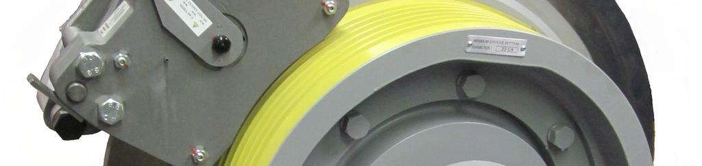
6 Standard Mounting Location #1 c. Brake Specifications 115 VDC model brake is supplied standard from the factory. Refer to Table 5. Brake Switch: Rating 250 VAC, 3A; Recommended Switching Current 24VDC, 10 to 50 ma; (Minimum 12VDC, 10mA) Switches can be wired: Normal Open, - Black & Blue wires - as shipped Normal Closed - Black & Gray wires Brake Model: Mayr 6 GL101 & GL171 Mayr 8 GL131 Mayr 10 GL130A, GL185, & GL260 Pick Voltage (VDC): 104@1.7A 104@2.27A 104@3.6 Pick Power (W): Hold Voltage (VDC): 52@.86A 52@1.14A 52@1.8 Hold Power (W): Resistance (ohms) Table 5 The machine brakes may be mounted in up to 5 locations around the body of the machine to provide flexibility in machine placement and proximity to other equipment or walls. Refer to Figure 1 for the standard and optional brake mounting locations. Optional Mounting Location #3 Standard Mounting Location #2 Optional Mounting Location #1 Optional Mounting Location #2 Figure 1 (4 brakes shown as representation only) Page 6 of 32


7 Top mount - Optional mounting location #3 Only available on some machines Consult Hollister-Whitney Engineering. If brakes are to be mounted using either of the optional mounting locations shown in Figure 1, mounting positions should be requested at the time of ordering. Brakes may be relocated in the field when necessary. Contact Hollister-Whitney for instructions. d. Machine Properties, Dimensions and Parts Lists See attachments in Section VIII Support Documentation at back of manual for machine dimensions and parts lists: GL101 Dimensions & Parts List GL131 Dimensions & Parts List GL171 Dimensions & Parts List GL130A Dimensions & Parts List GL185 Dimensions & Parts List GL260 Dimensions & Parts List III. Receipt, Handling, Storage and Commissioning a. Receipt Upon delivery of the machine, inspect the machine for damage. If any damage due to transportation is noted, contact the carrier and Hollister-Whitney. Check the machine data tag to ensure the machine conforms to your order. (An example data tag is shown in Figure 2.) b. Handling Figure 2 The machine will be delivered on wooden boards. The machine may be left on boards and moved with standard fork truck or pallet jack equipment. Page 7 of 32
8 When the machine is removed from boards, it must be moved by hoisting through holes provided in machine base. Figure 3 When hoisting the machine, mount and use hoisting rigging so that it does not rest against the machine. This will reduce the damage that might be cause during movement and installation. Use Table 6 to determine your specific machine weight. Weights are approx., since other options might be added by customer, (extra brakes, rope gripper, etc.) Machine Weight Model Weight Weight GL lbs. 910 kg GL lbs kg GL lbs kg GL130A 3900 lbs kg GL lbs kg GL lbs kg Table 6 Figure 3 DO NOT USE ANY OTHER MACHINE COMPONENT TO LIFT THE MACHINE! USE ONLY THE MACHINE BASE WHEN LIFTING AND MOVING THE MACHINE! HOISTING THE MACHINE BY ANY OTHER COMPONENT WILL RESULT IN DAMAGE TO THE MACHINE AND POSSIBLE FAILURE RESULTING IN THE MACHINE FALLING FROM THE HOISTING SYSTEM! Follow all the necessary safety precautions to avoid damage to the machine or risk to personnel when moving the machine. Page 8 of 32
 Disassembly of Machine VOIDS Warranty If disassembly must be done to get machine to final position please follow procedure below Step 1: Remove End Caps Use a hex wrench, loosen and remove (6)")
 Figure 4 Figure 5 Slide Outboard Stand off Base Fabrication.")
9 c. Disassembly / Reassembly (Disassembly of Machine is not recommended!) Disassembly of Machine VOIDS Warranty If disassembly must be done to get machine to final position please follow procedure below Step 1: Remove End Caps Use a hex wrench, loosen and remove (6) Outboard Stand End Cap bolts. (See Figure 4) Remove End Cap, slide Bearing End Cap against Traction Sheave Step 2: Remove Outboard Stand Mark front side of Outboard Stand. Loosen and remove Outboard Stand mounting bolts.(see Figure 5) Figure 4 Figure 5 Slide Outboard Stand off Base Fabrication. Do not force or put Outboard Stand in a bind, as this will cause damage to the Outboard Stand Bearing. NOTE: if shims are present under Outboard Stand, note their location and quantity. These shims will have to be placed in same location, to correctly align Outboards Stand to Motor upon reassembly. Step 3: Remove Motor from Base Fabrication Loosen and remove bolts holding Motor Housing to Base Fabrication. Remove plugs from top of Motor Housing, insert Hoisting Eye Bolts, lift Motor using eye bolts and pull straight up with spreader, or other rigging apparatus. (See Figure 6) Use eye bolts to lift only motor, not complete machine assembly If shims are present, note there location and quantity. Page 9 of 32


10 Figure 6 GL171 with 2 lifting eye bolts installed Figure 7 Step 4: Install Machine Follow guidelines below in section IV. Installation Step 5: Reassemble Machine on Base Fabrication Hoist Motor onto Base Fabrication. Remember to install shims where they were located in Step 3. Tighten bolts through Fabricated Base. Hoist Outboard Stand onto Base Fabrication. Remember to install shims where they were located in Step 2. When installing Outboard Stand use extreme care when sliding Stand over Bearing so that you don t bind the Outboard Stand Bearing in any way. Step 6: Check alignment of Outboard Stand to Motor Use a Dial Indicator mounted on a Magnetic Base. Set Magnetic Base on Motor Shaft and rest Indicator against Outboard Stand Bolting rim. Check Outboard Stand is in Alignment with Motor by turning motor by hand. Adjust Outboard stand as necessary and double check final alignment prior to removing indicator. (See Figure 7) Tighten Outboard Stand Bolts. Step 7: Install Caps: Slide Bearing End Cap against back of Outboard Stand. Install Front Bearing End Cap on Front of Outboard Stand. Bolt 2 End Caps together. Page 10 of 32 PUR #673 REV. B - LTL
11 d. Storage i. Short-Term Storage For short-term storage, place the machine in a warm, dry and clean environment. Protect the machine from harsh weather conditions and temperature variations that can lead to condensation. Protect the machine from dust, dirt and metal shavings. Metal dust and shavings can be attracted into the machine by the magnets. ii. Long-Term Storage e. Commissioning IV. Installation For long-term storage, place the machine in a sealed, waterproof enclosure with a dehydrating packet that is sized for the enclosure volume and humidity level. Follow the same instructions as outlined in Section III.d.i - "Short-term storage." Before the machine is installed, and before any voltage is applied, check the machine for condensation or any evidence of condensation or water. If any evidence of wetness is found, contact Hollister-Whitney for drying instructions. If wetness has been found and the machine has been dried, it will be necessary to re-verify the insulation between each coil phase and earth ground. Using an insulation tester (or megohm-meter), check the insulation resistance at 500 VDC. The resistance should be NO LESS than 100 Mohm. If the machine has gotten wet during transportation, contact the carrier and Hollister-Whitney. a. Machine Mounting Before hoisting the machine into place, verify all the hoisting equipment is rated for the weight of the machine. Refer to Table 6. Refer to Section III.b - "Handling" for the proper hoisting and handling procedures. Provide a level, structural support rated for the load on the machine. Ensure there is proper clearance around the machine for maintenance and adjustments. The machine may be mounted in traditional overhead and machine-room-less applications with down-pull on the traction sheave, or in basement set application with up-pull on the traction sheave. Special Machine Base fabrications are available for basement set applications. i. Traditional Overhead Anchor the machine base to the structural support using the mounting hole locations in the base. The bolts and washers required to anchor the machine base to the support, when not provided, should be Grade 5 minimum (Bolts adhering to ASTM A325 are also suitable), and of sufficient size and quantity to secure the machine from movement, with consideration for adherence to all applicable building codes and ASME A17.1. Page 11 of 32
12 Hollister-Whitney does not typically include the machine mounting hardware with the machine due to variations in structural machine support. ii. Basement Set Mounting Basement Set Machines are available, machine base fabrications and mounting plates specially designed for up-pull applications. Mounting plates are available for New Pour applications, and for adapting to Existing Structures. Refer to all applicable building codes and ASME A17.1 when selecting hardware (or other anchoring systems) to anchor the machine mounting plates to the structural supports in an up-pull application. Use the more stringent criteria between the building codes, ASME A17.1 and the minimum bolt grades identified in Section IV.a.i. b. Electrical Connections i. Machine Wiring BEFORE PERFORMING ANY ELECTRICAL CONNECTIONS, MAKE SURE THAT POWER SUPPLY IS TURNED OFF. ONLY THEN PROCEED WITH CONNECTING ELECTRICAL LEEDS TO POWER SUPPLY. NEVER WORK IN MACHINES ELECTRICAL ENCLOSURE WHILE POWER SUPPLY IS ON!!! Thermal Protection Switch (TPS) is wired with leads labeled and supplied into the machine electrical enclosure. Refer to Figure 8. Contacts are Normally Closed, opening if an overheat condition exists, and will close again after the machine has cooled to safe operating temperatures. Consult your controller manufacturer for appropriate TPS connections. Verify the electrical supply from the elevator drive and brake power supplies match the machine data tag. Refer to Figures 2. Connect the U-V-W lines from the drive as they correspond to motor. See Figure 8. Earth Ground connects to the ground lug terminal inside the electrical enclosure. Connect the machine and emergency brakes where shown in Figure 8. The brake switches are wired Normally Open from Hollister-Whitney. To change the switches to function as normally closed, remove the blue wire from the terminal block in the electrical enclosure, and replace it with the spare gray wire coming from the brake switch. NOTE The GL171 machine brakes are to be wired together to function as a single machine brake with the rope gripper (or second set of brakes) acting as the emergency brake. Kits are available for field relocation of the electrical enclosure. The electrical enclosure location can also be relocated at the factory at the time of machine assembly. THE MACHINE AND EMERGENCY BRAKE COILS MUST BE INDEPENDENT! IT IS THE RESPONSIBILITY OF THE USER TO CONNECT THE MOTOR IN ACCORDANCE WITH THE CURRENT LEGISLATION AND REGULATIONS IN THE COUNTRY OF USE. THIS IS PARTICULARLY IMPORTANT IN REGARDS TO WIRE SIZES USED TO CONNECT THE POWER AND EARTH GROUND AND THE TYPE AND SIZE OF FUSES. Page 12 of 32


13 Relocation of electrical box is an available option: Factory Installed Shown, Field Kit Available. Can be located at any open (see Figure 1) Brake Mounting position. Connect Earth Ground Here Attach Controller Wires this side Connect Machine Brake Coil Here THERMAL PROTECTION SWITCH WIRES Connect Machine Brake Switch Here Connect Emergency Brake Switch Here W Connect Emergency Brake Coil Here V U Figure 8 ii. Encoder wiring Connect the supplied encoder cable to the encoder on the back of the machine. When using a KEB drive, the encoder cable can be used "as-is." When using any other manufacturer's drive, consult control manufacturer for cable compatibility and availability. DO NOT modify the KEB cable without first consulting the control manufacturer. Any modification of the KEB cable voids the warranty. There are 2 cable classifications and each has its own color coding per cable. See attachments in Section VIII Support Documentation at end of manual for diagrams. 30m and under 00.F5.0C document 40m and over 00.F5.0C1-L005 document Page 13 of 32
14 c. Startup Verify all the motor related settings in the elevator controller match the information on the machine data tag. Refer to Figures 2. Verify that all the brake parameters match the information on the machine data tag. Refer to Figures 2. Remove any dirt, grease or rust that may have accumulated on the brake rotor during storage or installation. Use fine sandpaper or emery cloth with light pressure to remove rust from the rotor, taking care to keep the rust and metal dust out of the machine. Follow the controller manufacturer's procedure for alignment of the magnets. Briefly run the machine to verify the machine functionality and brake operation. Verify the drive sheave is plumb and aligned with the rope drop locations. Install the hoist ropes, adjust the rope shackles and check the ropes for equal tension. The rope tension must be uniform or it may cause vibration and premature wear on the traction sheave and hoist ropes. Re-verify the traction sheave is plumb once the machine is fully loaded. d. Brake Burnishing BRAKES MUST BE BURNISHED TO ACHIEVE FULL STOPPING TORQUE! Each brake on the machine must be burnished separately. Repeat the following procedure for each brake. Clamp the brake on the rotor. (De-energize the brake circuit.) Run the elevator in the direction of the load at 11 RPM for 1 minute If the overall travel of the elevator will not allow the burnishing time listed to be met on one pass, open (energize) the brake at the bottom of the hoist way, lift the load back to the top and repeat the run until the full burnishing time has been achieved. Stop occasionally to ensure the rotor and brake do not overheat. After burnishing, re-verify the air gap between the brake pads and the rotor. For brake check procedure and service follow Sections V.a. thru V.c. or VI.a. thru VI.c. Air gap should remain at approx inch *** NOTE: Air gap can surpass inch, but must not exceed inch. *** Page 14 of 32


15 e. Manual Brake Release (Optional Equipment) The manual brake release handle and cable is optional equipment that should be specified at the time of ordering. The standard cable length is 8'. Other lengths are available by special order. The brake release handle mounting plate may be mounted in any location that will be easily accessible to maintenance personnel. The manual brake release handle must be removed from the mounting plate prior to normal elevator operation. To remove the handle, loosen jam nut "A" on the handle and unscrew the handle from the brake release system. Figure 9 shows the manual brake release handle in place and Figure 10 shows the handle removed. (Brake handle mounting plate attached to back of machine for display only) A Figure 9 Figure 10 Page 15 of 32
470 Frame Synchronous AC Permanent Magnet Gearless Motors
 470 Frame Synchronous AC Permanent Magnet Gearless Motors AC Gearless Machines Imperial Alternating Current, Permanent Magnet, Gearless Machines are available in three frame sizes to suit a wide range
#92 DISC BRAKE ADJUSTMENTS # BRAKE MONITOR
 #92 DISC BRAKE ADJUSTMENTS #102-091 BRAKE MONITOR Page 1 of 11 HOLLISTER-WHITNEY DISC BRAKE WITH BRAKE MONITOR ADJUSTMENT PROCEDURE Page 2 of 11 HOLLISTER-WHITNEY DISC BRAKE WITH MONITOR SWITCH ADJUSTMENTS
Hollister-Whitney Elevator Corporation
 3/16/16 A 1 of 10 1171 Hollister-Whitney Elevator Corporation Governor Testing Instructions For Use with All 201, 202, 207, 207RS, 208, & 210 Governor Models Table of Contents I. Instructions for Testing
3946 en / a. This manual is to be given to. the end user. HPM x44. A.C. motor. Installation and maintenance
 This manual is to be given to the end user Installation and maintenance To ensure that the LEROY-SOMER motor you have just purchased is entirely satisfactory, it is essential to adhere to the following
INSTALLATION, OPERATION, AND MAINTENANCE MANUAL RBK FRP FAN
 Bulletin 62-January-20-09 ROOF UPBLAST & SIDEWALL CENTRIFUGAL FIBERGLASS EXHAUST FAN INSTALLATION, OPERATION, AND MAINTENANCE MANUAL RBK FRP FAN The M.K. Plastics catalog on the above corrosion resistant
SERVO MOTORS BRUSHLESS SERVO MOTORS OPERATING INSTRUCTIONS 2016
 SERVO MOTORS BRUSHLESS SERVO MOTORS OPERATING INSTRUCTIONS 2016 3009/16 en Ed.02.2016 Read these Operating Instructions before performing any transportation, installation, commissioning, maintenance or
BAH series Use and Maintenance Manual
 Page 1 of 15 BAH 225-280 series Use and Maintenance Manual Page 2 of 15 We would like to thank you for trusting us and buying our product. Field of application Before starting the motor, it s necessary
High Frequency SineWave Guardian TM
 High Frequency SineWave Guardian TM 380V 480V INSTALLATION GUIDE FORM: SHF-IG-E REL. January 2018 REV. 002 2018 MTE Corporation High Voltage! Only a qualified electrician can carry out the electrical installation
CR193 Vacuum Limitamp* Contactors
 GE Electrical Distribution GEH-5306C Maintenance Instructions CR193 Vacuum Limitamp* Contactors Contents Section 1 Introduction... 3 General... 3 Section 2 Description... 4 Principle of Operation... 4
DRUM BRAKE ADJUSTMENTS, MODELS #90, #100, #110 & #120 # BRAKE MONITOR
 DRUM BRAKE ADJUSTMENTS, MODELS #90, #100, #110 & #120 #102-092 BRAKE MONITOR Page 1 of 7 HOLLISTER-WHITNEY DRUM BRAKE WITH MONITOR ADJUSTMENTS IMPORTANT: READ ENTIRE INSTRUCTIONS BEFORE ATTEMPTING ADJUSTMENT!!!
Electric motor testing
 Electric motor testing MOTOR (MODELS EJ4-4001 AND EJ8-4001A) 23 GENERAL INFORMATION The vehicle is equipped with a 48-volt DC, shunt-wound, reversible traction motor. The shunt-wound motor is designed
DOCUMENT Service Manual 520 Frame Synchronous ACPM
 DOCUMENT 520 03162011 Service Manual 520 Frame Synchronous ACPM 520 Frame Synchronous ACPM Guarantee and Limitation of Warranties We guarantee that the apparatus manufactured by us will deliver its rated
Owner s Manual. ELECTRIC WIRE ROPE HOIST and TROLLEY RH SERIES
 EFFECTIVE: September 25, 2007 Owner s Manual ELECTRIC WIRE ROPE HOIST and TROLLEY RH SERIES 2 Ton through 20 Ton Capacity Product Code and Serial Number WARNING This equipment should not be installed,
STARTER - HITACHI Isuzu Trooper II DESCRIPTION TESTING STARTER PERFORMANCE TESTS Starters HITACHI. Isuzu
 STARTER - HITACHI 1986 Trooper II 1984 Starters HITACHI DESCRIPTION Starter is a conventional 12-volt, 4-pole brush-type motor, with direct or reduction gear drive. The starter-mounted solenoid shifts
PO Box 645, Stockton, Missouri, FAX superiorgearbox.com
 I000-7000-D0447-A 4/7/05 1 SAFETY PRECAUTIONS CAUTION Please read this entire document prior to operating the gear drive. Gear drive failure and / or injury to operators may be caused by improper installation,
GD-1 / GD-2 Sheave Brake
 GD-1 / GD-2 Sheave Brake Every attempt has been made to ensure that this documentation is as accurate and up-to-date as possible. However, Vertical Express assumes no liability for consequences, directly
PN: 6410T0022 Rev. 8/18/2014 Revision D Albany RR300 Stainless Mechanical Install & Owner s Manual
 PN: 6410T0022 Rev. 8/18/2014 Revision D Albany RR300 Stainless Mechanical Install & Owner s Manual ASSA ABLOY ENTRANCE SYSTEM. All Rights Reserved 975-A Old Norcross Road, Lawrenceville, Georgia 30046
SineWave Guardian TM 380V 600V INSTALLATION GUIDE. Quick Reference. ❶ How to Install Pages 6 17 ❷ Startup/Troubleshooting Pages WARNING
 SineWave Guardian TM 380V 600V INSTALLATION GUIDE FORM: SWG-IG-E REL. October 2018 REV. 003 2018 MTE Corporation High Voltage! Only a qualified electrician can carry out the electrical installation of
MGV25.X USER GUIDE. Ver. 3.1 INSTALLATION OPERATION AND MAINTENANCE MANUAL OF THE GEARLESS MGV25.X
 MGV25.X USER GUIDE INSTALLATION OPERATION AND MAINTENANCE MANUAL OF THE GEARLESS MGV25.X Ver. 3.1 MONTANARI GIULIO & C. S.r.l. 41100 MODENA (Italy) Via Bulgaria,39 Tel. +39 059 45.36.11 Fax +39 059 31.58.90
UltraSlim Mechanical Install & Owner s Manual
 PN: 6410T0020 Version C Rev: 5/01/2012 UltraSlim Mechanical Install & Owner s Manual Doors are Ultra-Tough, Ultra-Reliable, and Ultra-Affordable. ASSA ABLOY ENTRANCE SYSTEMS All Rights Reserved 975-A Old
Installation Instructions
 Preparing your vehicle to install your brake system upgrade 1. Rack the vehicle. 2. If you don t have a rack, then you must take extra safety precautions. 3. Choose a firmly packed and level ground to
INSTALLATION INSTRUCTIONS South Highway 11 Westminster, SC Toll Free (888) (864) FAX (864)
 (864) FAX (864)") 1.0 Purpose: To identify requirements for the replacement of ISS seals, o-ring and installation of gland nut to rod. 2.0 Scope: This instruction applies to the ISS units manufactured at Lift Technologies
1.0 Purpose: To identify requirements for the replacement of ISS seals, o-ring and installation of gland nut to rod. 2.0 Scope: This instruction applies to the ISS units manufactured at Lift Technologies
Caution Improper installation could result in tape failure, mounting hardware, and reader. Please read instructions before installing!
 Elgo Sensor Mounting Motion High Speed Landing/Positioning System The encoded tape used for the landing system is suspended between two mounting brackets that attach to the car rail using forged clips
RGZESDI Inverter Duty AC Induction Motors
 November 1999 RGZESDI Inverter Duty AC Induction Motors Installation Operation Maintenance Instructions Frames: 143T through S449SS/LS SIGNAL WORDS The signal words Danger, Warning and Caution used in
Derailment Detector Assembly
 Derailment Detector Assembly Every attempt has been made to ensure that this documentation is as accurate and up-to-date as possible. However, Vertical Express assumes no liability for consequences, directly
TubeTrace Tubing Bundles
 for Custom CEMS and Analytical Umbilicals English Units Receiving, Storing and Handling... 1. Inspect materials for damage incurred during shipping. Report damages to carrier for settlement. 2. Identify
INSTALLATION INSTRUCTIONS AMBASSADOR DRUM OVERHEAD SERIES 100 DUMBWAITER
 INSTALLATION INSTRUCTIONS AMBASSADOR DRUM OVERHEAD SERIES 100 DUMBWAITER The installation of Matot Drum Dumbwaiters should only be performed by qualified, experienced, and trained elevator installers.
SECTION ENCLOSED SWITCHES AND CIRCUIT BREAKERS
 SECTION 26 28 16 ENCLOSED SWITCHES AND PART 1 - GENERAL 1.1 SUMMARY A. Section includes the following individually mounted, enclosed switches and circuit breakers rated 600V AC and less: 1. Fusible switches.
SERVO MOTORS BRUSHLESS SERVO MOTORS ATEX ZONE 2-22 OPERATING INSTRUCTIONS 2016
 SERVO MOTORS BRUSHLESS SERVO MOTORS ATEX ZONE 2-22 OPERATING INSTRUCTIONS 2016 3010/16 en Ed.10.2016 Read these Operating Instructions before performing any transportation, installation, commissioning,
PO Box 645, Stockton, Missouri, FAX superiorgearbox.com W D0446-A 4/1/05 1
 W000-7000-D0446-A 4/1/05 1 SAFETY PRECAUTIONS CAUTION Please read this entire document prior to operating the gear drive. Gear drive failure and / or injury to operators may be caused by improper installation,
INSTRUCTION MANUAL. Anchor Darling 1878 Swing Check Valves. Installation Operation Maintenance. Sizes 1/2 through 2 FCD ADENIM
 INSTRUCTION MANUAL Anchor Darling 1878 Swing Check Valves Sizes 1/2 through 2 Installation Operation Maintenance FCD ADENIM0006-00 Table of Contents 1.0 Physical Description and Operation of Equipment
Slump Master III Slump Inspection and Safety Platform for Single & Double Units
 VERSION: SM88 G3.20 Inspection and Safety Platform for Single & Double Units Operating and Service Manual *Includes Parts List 2014 C & W Manufacturing and Sales Co. Dear Customer, C & W Manufacturing
Matrix AP 400V 690V INSTALLATION GUIDE. Quick Reference. ❶ How to Install Pages 6 20 ❷ Startup/Troubleshooting Pages WARNING
 Matrix AP 400V 690V INSTALLATION GUIDE FORM: MAP-IG-E REL. May 2017 REV. 002 2017 MTE Corporation WARNING High Voltage! Only a qualified electrician can carry out the electrical installation of this filter.
RH Electric Wire Rope Hoists
 RH Electric Wire Rope Hoists Harrington RH wire rope hoists are designed and built for today s heavy-duty wire rope hoist applications including fabricating, die handling, paper mill and production line
STARTER SYSTEM TESTING 5.6
 STARTER SYSTEM TESTING 5.6 ON-MOTORCYCLE TESTS Starter Relay Test NOTE Starter relay test also applies to ignition and key switch relays.. See Figure 5-5. Locate starter relay. The relay is attached to
Lbs Kgs Ft M
 Installation Instructions for 92600 ATV Winch 3000 lb. Rated Pull SPECIFICATIONS Rated line pull: 3000 lbs. (1360kgs) single line Motor: Permanent magnetic DC 12V with 1.2 hp. /0.9kw output Gear: Differential
CALIPER BRAKE INSTALLATION AND MAINTENANCE MANUAL
 CALIPER BRAKE INSTALLATION AND MAINTENANCE MANUAL WPT Power Corporation 1600 Fisher Road - Wichita Falls, TX 76305 P.O. Box 8148 - Wichita Falls, TX 76307 Ph. 940-761-1971 Fax 940-761-1989 www.wptpower.com
NorthStar. brand. Instruction Manual. SLIM Tach SL Thru-Shaft Diameter. Magnetoresistive Encoder Designed for GE Wind Energy
 NorthStar TM brand Instruction Manual SLIM Tach SL56 1.125 Thru-Shaft Diameter Magnetoresistive Encoder Designed for GE Wind Energy Patent Pending *791-1061-00* Rev. B Page 2 Table of Contents Chapter/Paragraph/Illustration
dv Sentry TM 208V 600V INSTALLATION GUIDE Quick Reference ❶ How to Install Pages 6 14 ❷ Startup/Troubleshooting Pages WARNING
 dv Sentry TM 208V 600V INSTALLATION GUIDE FORM: DVS-IG-E REL. January 2018 REV. 003 2018 MTE Corporation High Voltage! Only a qualified electrician can carry out the electrical installation of this filter.
SUREPOWR TM SERIES -SURE 49 FIELD INSTALLATION INSTRUCTIONS
 SUREPOWR TM SERIES -SURE 49 FIELD INSTALLATION INSTRUCTIONS Safety First In the maintenance and operation of mechanical equipment, SAFETY is the basic factor which must be considered at all times. Through
KT145 Series John Deere 6076 with Nippondenso Inj. Pump
 KT145 Series John Deere 6076 with Nippondenso Inj. Pump 30 Years Strong! Introduction The KT145 Series Governor System Installation Kit provides the necessary brackets and hardware to install a GAC precise
Top Drive System Installation and Commissioning Manual
 TDS-1000A Top Drive System Installation and Commissioning Manual SM01040 General Information Conventions.............................. 1-3 Notes, Cautions, and Warnings......................... 1-3 Illustrations.........................................
DRIVE AXLE Volvo 960 DESCRIPTION & OPERATION AXLE IDENTIFICATION DRIVE AXLES Volvo Differentials & Axle Shafts
 DRIVE AXLE 1994 Volvo 960 1994 DRIVE AXLES Volvo Differentials & Axle Shafts 960 DESCRIPTION & OPERATION All 960 station wagon models use type 1041 rear axle assembly. All 960 4-door models use type 1045
Service and Parts Manual. NO LONGER IN PRODUCTION Some service parts may not be available for this product. Otolaryngology Chair.
 thru 391-001 -002 Otolaryngology Chair Serial Number Prefixes: EN, PD & V Service and Parts Manual NO LONGER IN PRODUCTION Some service parts may not be available for this product. 391-001 thru -002 NOTE:
Installation and Service Instructions for 87,000 & 87,100 Series Self-Adjust Brakes (rev. B)
") Spring-Set Disc Brakes P/N 8-078-98-0 effective 6/6/0 Installation and Service Instructions for 87,000 & 87,00 Series Self-Adjust Brakes (rev. B) Tools required for installation and servicing: 3/8 hex
Spring-Set Disc Brakes P/N 8-078-98-0 effective 6/6/0 Installation and Service Instructions for 87,000 & 87,00 Series Self-Adjust Brakes (rev. B) Tools required for installation and servicing: 3/8 hex
MG300 USER GUIDE. Ver. 3.2 INSTALLATION OPERATION AND MAINTENANCE MANUAL OF THE GEARLESS MG300.4, MG300.6, MGV30.4 AND MGV30.6
 MG300 USER GUIDE INSTALLATION OPERATION AND MAINTENANCE MANUAL OF THE GEARLESS MG300.4, MG300.6, MGV30.4 AND MGV30.6 Ver. 3.2 MONTANARI GIULIO & C. S.r.l. 41100 MODENA (Italy) Via Bulgaria,39 Tel. +39
REAR AXLE Click on the applicable bookmark to selected the required model year
 REAR AXLE 27-1 REAR AXLE CONTENTS GENERAL INFORMATION.................. 2 SERVICE SPECIFICATIONS................. 3 LUBRICANTS.............................. 3 SEALANTS AND ADHESIVES.............. 4 SPECIAL
Trimline Car and Sling
 Trimline Car and Sling Every attempt has been made to ensure that this documentation is as accurate and up-to-date as possible. However, Vertical Express assumes no liability for consequences, directly
VA-908x Series Electric Rotary Actuators for Two-Position and Modulating Service
 VA-908x Series Electric Rotary Actuators for Two-Position and Modulating Service Installation Instructions VA-908x Code No. LIT-12011566 Issued August 24, 2009 Applications The VA-908x Series Electric
Syntron EB-00 Vibratory Parts Feeder GENERAL MANUAL
 Syntron EB-00 Vibratory Parts Feeder GENERAL MANUAL INSTALLATION OPERATION MAINTENANCE Thank you for buying your equipment from Homer City Automation Inc. This manual will help you to understand how your
Ladder Safety Program
 Ladder Safety Program For Adopted LC-1022 Rev. 06/16 Page 1 I. Introduction The Organization recognizes that employees use ladders on a regular
Instructions for MB832 Manual Barrier Ver0614
 Instructions for MB832 Manual Barrier Ver0614 Read all the instructions before starting It is recommended that Locktite Blue brand thread sealant be used for all arm and pivot bolts as added protection
OEM TM-50 Quick Start Guide
 This quick start guide provides basic setup and operating instructions for the OEM TM-50. The intended use of the OEM TM-50 Taping Machine is to produce taped reels of individually sealed and consistently
MGV25.X USER GUIDE. Ver. 3.7 INSTALLATION OPERATION AND MAINTENANCE MANUAL OF THE GEARLESS MGV25.2 MGV25.3 MGV25.5
 MGV25.X USER GUIDE INSTALLATION OPERATION AND MAINTENANCE MANUAL OF THE GEARLESS MGV25.2 MGV25.3 MGV25.5 Ver. 3.7 MONTANARI GIULIO & C. S.r.l. 41100 MODENA (Italy) Via Bulgaria,39 Tel. +39 059 45.36.11
PISTON ACCUMULATOR INSTALLATION, OPERATION & CARE
 PISTON ACCUMULATOR INSTALLATION, OPERATION & CARE www.accumulators.com The user is the sole responsible party to ensure proper selection, installation, operation and maintenance of these products and to
MODEL 660 AUTOMATIC FASTENING CENTER OPERATOR S MANUAL
 MODEL 660 AUTOMATIC FASTENING CENTER OPERATOR S MANUAL Copyright: January 13, 2003 Revised: 080612 Serial No. 0506113. 1 TABLE OF CONTENTS INTRODUCTION..3 OPERATOR SAFETY... 3 SYSTEM REQUIREMENTS..4 INSTALLATION
Helix Curved Stair Lift Installation & Service Manual
 Helix Curved Stair Lift Installation & Service Manual WARNING! Strict adherence to these installation instruction IS required to promote the safety of those installing this product, as well as that of
SERVICE MANUAL L130B / L4130 Series Logstacker Drive Axle With Bolt-On Stub End Retainer
 SERVICE MANUAL L130B / L4130 Series Logstacker Drive Axle With Bolt-On Stub End Retainer Page 1 Allied Form #80-930 Rev 07/2009 SERVICE MANUAL LOG STACKER DA202 DRIVE AXLE TABLE OF CONTENTS PROCEDURE FOR
Operation and Maintenance Manual for Multipurpose Actuators. 120 VAC Actuator 12 VDC Actuator 12 VDC Actuator
 Joyce/Dayton Corp. Operation and Maintenance Manual for Multipurpose Actuators 120 VAC Actuator 12 VDC Actuator 12 VDC Actuator The recommendations in this manual for installation, operation and maintenance
Operating Instructions
 Operating Instructions MARSHALL STABILITY TESTER Models: 45-6829/01 (AP-170E-8) 45-6829/02 (AP-170E) 45-6829/06 (AP-170E-2) TABLE OF CONTENTS I. GENERAL INFORMATION... 1 II. RELATED USER DOCUMENTATION...
LEXUS IS 250 Front Performance Brake Kit Section I - Installation Preparation
 LEXUS IS 250 Front 2006- Performance Brake Kit Section I - Installation Preparation Part Number: PTR09-53080 Kit Contents Item # Quantity Reqd. Description 1 1 Brake Rotor, LH Front 2 1 Brake Rotor, RH
1984 Toyota Pickup. IGNITION SYSTEM - NIPPONDENSO ELECTRONIC' '1984 ELECTRICAL Toyota Ignition System - Nippondenso Electronic Ignition
 ADJUSTMENTS 1984 Toyota Pickup PICK-UP COIL-TO-SIGNAL ROTOR (RELUCTOR) AIR GAP 1. Using a flat, non-magnetic feeler gauge, check air gap between pick-up coil pole piece and each reluctor tooth. Gaps should
SUZHOU TORIN DRIVE EQUIPMENT CO., LTD.
 Permanent Magnet Synchronous Gearless Traction Machine TPM1 Series PMS Gearless Elevator Traction Machine Complete Operation and Service Manual SUZHOU TORIN DRIVE EQUIPMENT CO., LTD. Manual No. TDI-003A-TPM1
KT230 Series Caterpillar 3406 Governor System Installation Kit
 KT230 Series Caterpillar 3406 Governor System Installation Kit 30 Years Strong! Introduction The KT230 Series Governor System Installation Kit provides the necessary brackets and hardware to install a
M T E C o r p o r a t i o n. dv/dt Filter. Series A VAC USER MANUAL PART NO. INSTR REL MTE Corporation
 M T E C o r p o r a t i o n dv/dt Filter Series A 440-600 VAC USER MANUAL PART NO. INSTR - 019 REL. 041119 2004 MTE Corporation IMPORTANT USER INFORMATION NOTICE The MTE Corporation dv/dt Filter is designed
INSTRUCTION MANUAL FOR THE CLINICAL 50 CENTRIFUGE
 INSTRUCTION MANUAL FOR THE CLINICAL 50 CENTRIFUGE 82013-800 January 2006 INDEX PAGE 1. General Information... 2 1.1 Description... 2 1.2 Safety precautions to be observed before operating the centrifuge...
INSTALLATION MANUAL FOR EVO BRAKES
 INSTALLATION MANUAL FOR EVO BRAKES DATE OF CREATION: 18/03/2013 DATE OF REVIEW: 13/11/2017 REACH: EVO-01/EVO-05 REVIEW: ES13 1 / 31 ÍNDICE 1 SAFETY INSTRUCTIONS:... 3 1.1 Symbols used:... 3 1.2 General
OVERLOAD CLUTCHES FOR INDEX DRIVES
 The Driving Force in Automation OVERLOAD CLUTCHES FOR INDEX DRIVES WARNING WARNING This is a controlled document. It is your responsibility to deliver this information to the end user of the CAMCO indexer.
ALL700RM-230V INSTALLATION INSTRUCTIONS
 ALL700RM-230V INSTALLATION INSTRUCTIONS Aladdin Light Lift, Inc. (256) 429-9700 61 Shields Road (877) 287-4601 Huntsville, AL 35811 www.aladdinlightlift.com Patent #5105349 WARNING: Disconnect power source
Operator s Manual A-1 Series EZ Rig Crane
 Manual No. 00201 February 2009 Operator s Manual A-1 Series EZ Rig Crane WARNING: Before operating this lift, read and understand this operator s manual. Become familiar with the potential hazards associated
Mitsubishi Turbine: Hybrid XT Control Sensor Retrofit
 Mitsubishi Turbine: Hybrid XT Control Sensor Retrofit NIPPON ANEMOMETER TO HYBRID XT ANEMOMETER RETROFIT KIT, MITSUBISHI, NEI (9370) NIPPON YAW VANE TO HYBRID XT VANE RETROFIT KIT, MITSUBISHI, NEI (9371)
SUREPOWR TM SERIES -SURE 24/25 FIELD INSTALLATION INSTRUCTIONS
 SUREPOWR TM SERIES -SURE 4/5 FIELD INSTALLATION INSTRUCTIONS Safety First In the maintenance and operation of mechanical equipment, SAFETY is the basic factor which must be considered at all times. Through
Installation and Service Manual
 RESIDENTIAL PLATFORM LIFTS RPL400 / RPL600 Installation and Service Manual WARNING! STRICT ADHERENCE TO THESE INSTALLATION INSTRUCTIONS IS REQUIRED to promote the safety of those installing this product,
2.0 CONSTRUCTION AND OPERATION 3.0 CHARACTERISTICS K. CO (HI-LO) Overcurrent Relay
 Overcurrent Relay") 41-100K 2.0 CONSTRUCTION AND OPERATION The type CO relays consist of an overcurrent unit (CO), either an Indicating Switch (ICS) or an ac Auxiliary Switch (ACS) and an Indicating Instantaneous Trip unit
41-100K 2.0 CONSTRUCTION AND OPERATION The type CO relays consist of an overcurrent unit (CO), either an Indicating Switch (ICS) or an ac Auxiliary Switch (ACS) and an Indicating Instantaneous Trip unit
Electrically Released Brakes ERS VAR11-01 FT = 4100 N
 SM429gb - rev 06/11 S E R V I C E Electrically Released Brakes ERS VAR11-01 FT = 4100 N M A N U A L EC type certificate ABV 775/1 According to drawing 1 12 106946 TUV SUD Industrie Service WARNER ELECTRIC
APPENDIX B SPECIFICATION FOR GENERATOR OVERHAUL EMD MODEL AR10 D18... B-1
 Table of Contents APPENDIX B SPECIFICATION FOR GENERATOR OVERHAUL EMD MODEL AR10 D18... B-1 B.01 SCOPE... B-1 B.02 GENERAL... B-1 B.03 ELECTRICAL QUALIFICATION... B-1 B.04 EQUIPMENT RECONDITIONING... B-2
Complete Operation and Service Manual
 Overhead Geared Elevator Traction Machine TGD1 Geared Machine with optional sheave brake Complete Operation and Service Manual Manual No. TDI-004-TGD1 Contents Limited Liability, Warranty and Safety Precautions
Instruction Manual For DODGE. Airport Baggage Handling Systems Speed Reducers
 Instruction Manual For DODGE Airport Baggage Handling Systems Speed Reducers ABHS TXT109 - TXT115 - TXT125 ABHS TXT209 - TXT215 - TXT225 ABHS TXT309A - TXT315A - TXT325A ABHS TXT409A - TXT415A - TXT425A
THE COMPLETE ELEVATOR MODERNIZATION SOLUTION. KONE ReVolution
 THE COMPLETE ELEVATOR MODERNIZATION SOLUTION KONE ReVolution The complete elevator modernization solution KONE ReVolution is a complete elevator system upgrade which will improve the performance of your
OEM Manual. 4042SA Leak Detecting Spill Alarm Instruction manual
 OEM Manual 4042SA Leak Detecting Spill Alarm Instruction manual 1 These instructions generally describe the installation, operation, and maintenance of, subject equipment. The manufacturer reserves the
COOPER POWER SERIES. Edison Modular Fuse (EMF) Installation Instructions. Fusing Equipment MN132031EN
 Installation Instructions. Fusing Equipment MN132031EN") Fusing Equipment MN132031EN Effective November 2016 Supersedes July 2008 (S240-92-1) COOPER POWER Edison Modular Fuse (EMF) Installation Instructions SERIES DISCLAIMER OF WARRANTIES AND LIMITATION OF LIABILITY
Fusing Equipment MN132031EN Effective November 2016 Supersedes July 2008 (S240-92-1) COOPER POWER Edison Modular Fuse (EMF) Installation Instructions SERIES DISCLAIMER OF WARRANTIES AND LIMITATION OF LIABILITY
OFI MODEL 130 HTHP BENCHTOP CONSISTOMETER INSTRUCTIONAL MANUAL
 OFI MODEL 130 HTHP BENCHTOP CONSISTOMETER INSTRUCTIONAL MANUAL OPERATING INSTRUCTIONS OFI MODEL 130 BENCHTOP HPHT CONSISTOMETER OFI MODEL 130 BENCHTOP HPHT CONSISTOMETER GENERAL The OFI Model 130 Consistometer
Installation Manual. For. Alumavator and Platinum. Vertical Installation. Elevator Boat Lifts
 Installation Manual For Alumavator and Platinum Vertical Installation Elevator Boat Lifts Page 2 Safety Precautions 1. Your boat lift is a heavy duty piece of equipment. It is important that all persons
Instructions for INSTALLATION -- OPERATION -- MAINTENANCE of the SELAS AIR/GAS BLENDER VALVE. (for PROPANE/AIR, BUTANE/AIR AND OTHER BLENDS)
") DESCRIPTION The SELAS Blender Valve is a three-port, adjustable area valve which accurately mixes any two of a wide variety of gases. Air and Gas ports in a movable piston are matched to complimentary
DESCRIPTION The SELAS Blender Valve is a three-port, adjustable area valve which accurately mixes any two of a wide variety of gases. Air and Gas ports in a movable piston are matched to complimentary
M T E C o r p o r a t i o n MATRIX FILTER. SERIES B Volts, 50HZ USER MANUAL PART NO. INSTR REL MTE Corporation
 M T E C o r p o r a t i o n MATRIX FILTER SERIES B 380-415 Volts, 50HZ USER MANUAL PART NO. INSTR - 015 REL. 060628 2006 MTE Corporation IMPORTANT USER INFORMATION NOTICE The MTE Corporation Matrix Filter
SUZHOU TORIN DRIVE EQUIPMENT CO., LTD.
 Overhead Geared Elevator Traction Machine IGD20 Geared Machine Complete Operation and Service Manual SUZHOU TORIN DRIVE EQUIPMENT CO., LTD. Manual No. TDII-003-IGD20 Overhead Geared Elevator Traction Machine
VHM-P (Non-Locking) and VHM-PL (Locking) Variable Height Arm with Slide-In Mounting Plate
 and VHM-PL (Locking) Variable Height Arm with Slide-In Mounting Plate") 3875 Cypress Drive Petaluma, CA 94954 800.228.2555 +1.707.773.1100 Fax 707.773.1180 www.gcx.com VHM-P (Non-Locking) and VHM-PL (Locking) Variable Height Arm with Slide-In Mounting Plate (Refer to qualified
3875 Cypress Drive Petaluma, CA 94954 800.228.2555 +1.707.773.1100 Fax 707.773.1180 www.gcx.com VHM-P (Non-Locking) and VHM-PL (Locking) Variable Height Arm with Slide-In Mounting Plate (Refer to qualified
F O R M. Installation and Maintenance Manual for FCR Equipped Motors and Gearmotors. 9055E Revised October 2015
 Installation and Maintenance Manual for FCR Equipped Motors and Gearmotors Power Transmission Solutions Regal Beloit America, Inc. 7120 New Buffington Road Florence, KY 41042 Application Engineering: 800
STARTER SYSTEM TESTING 5.6
 STARTER SYSTEM TESTING 5.6 ON-MOTORCYCLE TESTS b088x5x Starter Relay Test NOTE Starter relay test also applies to ignition and key switch relays.. See Figure 5-5. Locate starter relay. The relay is attached
Installation and Service Instructions for Self Adjust Brakes 81,000 Series
 Spring-Set Disc Brakes P/N -07-9-00 effective 07/0/0 Installation and Service Instructions for Self Adjust Brakes,000 Series Current revision available @ www.stearns.rexnord.com Tools required for installation
Tool-less Hinged Closure Installation, Operation, & Maintenance
 2612 Howard Street Louisville, KY 40211 USA Phone 502-774-6011 Fax 502-774-6300 Website: www.tubeturns.com For genuine Tube Turns Closure parts please contact factory: ttaftermarket@sypris.com Bulletin
MARLEY ENGINEERED PRODUCTS OPERATING INSTRUCTIONS AND PARTS LIST
 MARLEY ENGINEERED PRODUCTS OPERATING INSTRUCTIONS AND PARTS LIST TUBE AXIAL DUCT FANS INDUSTRIAL PROPELLER FANS INDUSTRIAL ROOF EXHAUSTERS HEAVY DUTY MAN/PRODUCT COOLERS WARNING BY ACCEPTANCE OF THIS MERCHANDISE,
Start-up and Operation
 Start-up and Operation NEVER FORGET THAT ANY MACHINE CAN BE VERY DANGEROUS WHEN NOT OPERATED CORRECTLY AND SAFELY. ALWAYS VISUALLY CHECK TO MAKE SURE THAT ALL PERSONS ARE CLEAR BEFORE TURNING ON ANY CONTROLS.
actiin4085 fr / a This notice must be given to the end user GEARLESS XA2 A.C. Drive for lifts Installation and maintenance
 actiin This notice must be given to the end user Installation and maintenance SUMMARY 1 -DELIVERY... 3 2 -STORAGE... 4 2.1 -Storage facility... 4 2.2 -Extended storage (> 3 months)... 4 3 -ENVIRONMENT...
Tri-Spark Ignition System Installation Triple Cylinder TRI-0001
 Tri-Spark Ignition System Installation Triple Cylinder TRI-0001 There are potentially lethal high voltages produced at the ignition coils and spark plugs, therefore every precaution must be taken to prevent
HORSTMAN GREASED LIGHTNING CLUTCH
 HORSTMAN GREASED LIGHTNING CLUTCH Horstman s Greased Lightning (GL) clutch is designed for ultra high performance, and requires expert setup and a serious commitment to maintenance. Warning!!! 1. Clutch
FD 120 Card Cutter MAINTENANCE MANUAL. MyBinding.com 5500 NE Moore Court Hillsboro, OR Toll Free: Local: /2011
 FD 120 Card Cutter 5/2011 MAINTENANCE MANUAL SAFETY PRECAUTIONS Always observe the cautions and warnings given below to prevent personal injury or property damage. The degree of danger and damage that
CAT-1 Series 3. Installation Guide. The Valley Group, Inc. 871 Ethan Allen Hwy. Suite 104 Ridgefield, CT 06877
 CAT-1 Series 3 Installation Guide The Valley Group, Inc. 871 Ethan Allen Hwy. Suite 104 Ridgefield, CT 06877 (203) 431-0262 (203) 431-0296 FAX tvg@cat-1.com Installation of Load Cells for CAT-1 Systems
ALL700/ALL700-CM INSTALLATION INSTRUCTIONS
 ALL700/ALL700-CM INSTALLATION INSTRUCTIONS Aladdin Light Lift, Inc. (256) 429-9700 61 Shields Road (877) 287-4601 Huntsville, AL 35811 www.aladdinlightlift.com Patent #5105349 WARNING: Disconnect power
SERIES G3DB/AG3DB ELEVATOR
 TM INSTRUCTIONS AND PARTS LIST SERIES G3DB/AG3DB ELEVATOR WARNING This manual, and GENERAL INSTRUCTIONS MANUAL, CA-1, should be read thoroughly prior to pump installation, operation or maintenance. SRM00059