INSTALLATION AND OPERATION MANUAL
|
|
|
- Jasmin Perkins
- 5 years ago
- Views:
Transcription


1 6,000 LB. CAPACITY / 2722 KG. Mid-RISE SCISSOR LIFT Models: MDS-6K MDS-6KF IMPORTANT SAFETY INSTRUCTIONS SAVE THESE INSTRUCTIONS Please read THE ENTIRE CONTENTS OF THIS MANUAL prior to installation AND OPERATION. BY PROCEEDING WITH LIFT INSTALLATION AND OPERATION YOU AGREE THAT YOU FULLY UNDERSTAND AND COMPREHEND THE FULL CONTENTS OF THIS MANUAL. FORWARD THIS MANUAL TO ALL OPERATORS. Failure to operate this equipment as directed may cause injury OR DEATH. INSTALLATION AND OPERATION MANUAL Rev A 02/05/16 P/N RECEIVING The shipment should be thoroughly inspected as soon as it is received. The signed Bill of Lading is acknowledgement by the shipping carrier as receipt of this product as listed in your invoice as being in a good condition of shipment. If any of these goods listed on this Bill of Lading are missing or damaged, do not accept goods until the shipping carrier makes a notation on the freight bill of the missing or damaged goods. Do this for your own protection. BE SAFE Your new lift was designed and built with safety in mind. However, your overall safety can be increased with proper training and thoughtful operation on the part of the operator. DO NOT operate or repair this equipment without reading this manual and the important safety instructions shown inside. Keep this operation manual near the lift at all times. Make sure that all users read and understand this manual Lemonwood Dr. Santa Paula, CA , USA Toll Free Tel: Fax:
2 6,000 POUND CAPACITY LOW RISE PIT LIFT This instruction manual has been prepared especially for you. Your new lift is the product of over 40 years of continuous research, testing and development; it is the most technically advanced lift on the market today. READ THIS ENTIRE MANUAL BEFORE INSTALLATION & OPERATION BEGINS RECORD HERE THE LIFT AND POWER UNIT INFORMATION WHICH IS LOCATED ON THE SERIAL NUMBER DATA PLATES ON THE LIFT AND ON THE POWER UNIT Model NuMber Serial NuMber Santa Paula, CA USA Power Unit Model # Power Unit Date Of Mfg. Power Unit Serial # Max Operating Pressure 1,650 PSI lift CapaCity description Voltage VAC, Hz, 1 Ph VAC, Hz, 3 Ph VAC, Hz, 1 Ph VAC, Hz, 3 Ph date of Mfg. DANGER! Disconnect Power Before Servicing WArrAnty void if DAtA PlAte is removed PN This information is required when calling for parts or warranty issues. PRODUCT WARRANTY Our comprehensive product warranty means more than a commitment to you; it s also a commitment to the value of your new MDS-6K BendPak lift. For full warranty details and to register your new lift contact your nearest BendPak dealer or visit: / support/ warranty/ What is not covered under this warranty: a. Any failure that results from Purchaser s abuse, neglect or failure to operate, maintain or service product in accordance with instructions provided in the owner s manual(s) supplied. b. Any damage caused by overloading lift beyond rated capacity. c. Items or service normally required to maintain the product, i.e. lubricants, oil, etc. d. Items considered general wear parts such as rubber pads, lifting cables, etc. unless wear or failure is a direct result of manufacturer defect due to material and/or workmanship. e. Any component damaged in shipment or any failure caused by installing or operating lift under conditions not in accordance with installation and operation guidelines or damaged by contact with tools or surroundings. f. Motor or pump failure caused by rain, excessive humidity, corrosive environments or other contaminants. g. Rusted components due to improper maintenance or corrosive environments. h. Cosmetic defects that do not interfere with product functionality. i. Damage due to incorrect voltage or improper wiring. j. Any incidental, indirect, or consequential loss, damage or expense that may result from any defect, failure or malfunction of BendPak Inc. product. k. All electrical components (excluding power unit) are guaranteed for one year against defects in workmanship and/or materials when the lift is installed and used according to specifications. NOTE: Every effort has been taken to ensure complete and accurate instructions have been included in this manual, however, possible product updates, revisions and or changes may have occurred since this printing. BendPak Ranger reserves the right to change specifications without incurring any obligation for equipment previously or subsequently sold. Not responsible for typographical errors. 2
3 IMPORTANT NOTICE Do not attempt to install this lift if you have never been trained on basic automotive lift installation procedures. Never attempt to lift components without proper lifting tools such as forklift or cranes. Stay clear of any moving parts that can fall and cause injury. These instructions must be followed to ensure proper installation and operation of your lift. Failure to comply with these instructions can result in serious bodily harm and void product warranty. Manufacturer will assume no liability for loss or damage of any kind, expressed or implied resulting from improper installation or use of this product. Please read entire manual prior to installation. Definitions of Hazard LevelS Identify the hazard levels used in this manual with the following definitions and signal words: Owner s Responsibility To maintain the lift and user safety, the responsibility of the owner is to read and follow these instructions: t t t t t t t t t Follow all installation and operation instructions. Make sure installation conforms to all applicable Local, State, and Federal Codes, Rules, and Regulations; such as State and Federal OSHA Regulations and Electrical Codes. Carefully check the lift for correct initial function. Read and follow the safety instructions. Keep them readily available for machine operators. Make certain operators are properly trained, know how to safely and correctly operate the unit, and are properly supervised. Allow unit operation only with all parts in place and operating safely. Carefully inspect the unit on a regular basis and perform all maintenance as required. Service and maintain the unit only with authorized or approved replacement parts. Keep all instructions permanently with the unit and all decals on the unit clean and visible. Before You Begin Watch for this symbol. It means: Immediate hazards which will result in severe personal injury or death. Receiving: The shipment should be thoroughly inspected as soon as it is received. The signed bill of lading is acknowledgement by the carrier of receipt in good condition of shipment covered by your invoice. If any of the goods called for on this bill of lading are shorted or damaged, do not accept them until the carrier makes a notation on the freight bill of the shorted or damaged goods. Do this for your own protection. Watch for this symbol. It means: Hazards or unsafe practices which could result in severe personal injury or death. NOTIFY THE CARRIER AT ONCE if any hidden loss or damage is discovered after receipt and request the carrier to make an inspection. If the carrier will not do so, prepare a signed statement to the effect that you have notified the carrier (on a specific date) and that the carrier has failed to comply with your request. Watch for this symbol. It means: Hazards or unsafe practices which may result in minor personal injury, product or property damage. IT IS DIFFICULT TO COLLECT FOR LOSS OR DAMAGE AFTER YOU HAVE GIVEN THE CARRIER A CLEAR RECEIPT. File your claim with the carrier promptly. Support your claim with copies of the bill of lading, freight bill, invoice, and photographs, if available. Our willingness to assist in helping you process your claim does not make BendPak responsible for collection of claims or replacement of lost or damaged materials. 3
4 Table of Contents Contents Page No. Warranty / Serial Number Definitions of Hazard Levels Owner s Responsibility Before You Begin Installer / Operator Agreement/ Protective Equipment Safety / Warning Instructions Tools Required Step 1 / Selecting Site Step 2 / Floor Requirements Concrete Specifications Main Assembly View / Parts Inventory Floor Plan / Layout Dimensions Specifications Clearances Step 3 / Locating Unit Step 4 / Locating Power Unit Console Step 5 / Power Console Hose Routing Step 6 / Flow Divider / Hydraulic Hose Installation Step 7 / Power Unit Installation Step 8 / Routing Air Line Hoses Step 9 / Anchoring Lift Assemblies Step 10 / Bleeding Step 11 / Lift Start Up / Final Adjustments Step 12 / Operation Instructions Lift Operation Safety Maintenance Instructions Safe Lift Operation MDS-6K & MDS-6KF Labels Labels Positioning Troubleshooting Guide Bolt Torque Specifications Installation Agreement Parts Listing Wiring Diagram Maintenance Records

5 INSTALLER / OPERATOR PLEASE READ AND FULLY UNDERSTAND. BY PROCEEDING YOU AGREE TO THE FOLLOWING: t I have visually inspected the site where the lift is to be installed and verified the concrete to be in good condition and free of cracks or other defects. I understand that installing a lift on cracked or defective concrete could cause lift failure resulting in personal injury or death. t I understand that a level floor is required for proper installation and level lifting. t I understand that I am responsible if my floor is of questionable slope and that I will be responsible for all charges related to pouring a new level concrete slab if required and any charges. t I understand that some Bendpak lifts are supplied with concrete fasteners meeting the criteria of the American National Standard Automotive Lifts - Safety Requirements for Construction, Testing, and Validation ANSI/ALI ALCTV-2011, and that I will be responsible for all charges related to any special regional structural and/ or seismic anchoring requirements specified by any other agencies and/or codes such as the Uniform Building Code (UBC) and/or International Building Code (IBC). t I will assume full responsibility for the concrete floor and condition thereof, now or later, where the above equipment model(s) are to be installed. Failure to follow danger, warning, and caution instructions may lead to serious personal injury or death to operator or bystander or damage to property. t I understand that BendPak lifts are designed to be installed in indoor locations only. Failure to follow installation instructions may lead to serious personal injury or death to operator or bystander or damage to property or lift. Please read entire manual prior to installation. Do not operate this machine until you read and understand all the dangers, warnings and cautions in this manual. For additional copies or further information, contact: BendPak Inc. / Ranger Products 1645 Lemonwood Dr. Santa Paula, CA INSTALLER / OPERATOR Protective Equipment Personal protective equipment helps makes installation and operation safer, however, it does not take the place of safe operating practices. Always wear durable work clothing during any installation and/or service activity. Shop aprons or shop coats may also be worn, however loose fitting clothing should be avoided. Tight fitting leather gloves are recommended to protect technician hands when handling parts. Sturdy leather work shoes with steel toes and oil resistant soles should be used by all service personnel to help prevent injury during typical installation and operation activities. Eye protection is essential during installation and operation activities. Safety glasses with side shields, goggles, or face shields are acceptable. Everyday eyeglasses only have impact resistant lenses, they are not safety glasses. Back belts provide support during lifting activities and are also helpful in providing worker protection. Consideration should also be given to the use of hearing protection if service activity is performed in an enclosed area, or if noise levels are high. Failure to follow danger, warning, and caution instructions may lead to serious personal injury or death to operator or bystander or damage to property. THIS SYMBOL POINTS OUT IMPORTANT SAFETY INSTRUCTIONS WHICH IF NOT FOLLOWED COULD ENDANGER THE PERSONAL SAFETY AND/OR PROPERTY OR YOURSELF AND OTHERS AND CAN CAUSE PERSONAL INJURY OR DEATH. READ AND FOLLOW ALL INSTRUCTIONS IN THIS MANUAL BEFORE ATTEMPTING TO OPERATE THIS MACHINE. 5


6 1. Carefully remove the crating and packing materials. CAUTION! Be careful when cutting steel banding material as items may become loose and fall causing personal harm or injury. INTRODUCTION 2. Check the voltage, phase and proper amperage requirements for the motor shown on the motor plate. Wiring should be performed by a certified electrician only. IMPORTANT SAFETY INSTRUCTIONS Read these safety instructions entirely IMPORTANT NOTICE Do not attempt to install this lift if you have never been trained on basic automotive lift installation procedures. Never attempt to lift components without proper lifting tools such as forklift or cranes. Stay clear of any moving parts that can fall and cause injury. 1. Read and understand all instructions and all safety warnings before operating lift. 2. Care must be taken as burns can occur from touching hot parts. 3. Do not operate equipment with a damaged cord or if the equipment has been dropped or damaged until it has been examined by a qualified service person. 4. Do not let a cord hang over the edge of the table, bench, or counter or come in contact with hot manifolds or moving fan blades. 5. If an extension cord is necessary, a cord with a current rating equal to or more than that of the equipment should be used. Cords rated for less current than the equipment may overheat. Care should be taken to arrange the cord so that it will not be tripped over or pulled. 6. Always unplug equipment from electrical outlet when not in use. Never use the cord to pull the plug from the outlet. Grasp plug and pull to disconnect. 7. Let equipment cool completely before putting away. Loop cord loosely around equipment when storing. 8. To reduce the risk of fire, do not operate equipment in the vicinity of open containers of flammable liquids (gasoline). 9. Adequate ventilation should be provided when working on operating internal combustion engines. 10. Keep hair, loose clothing, fingers, and all parts of body away from moving parts. Keep feet clear of lift when lowering. Avoid pinch points. 11. DANGER. To reduce the risk of electric shock, do not use on wet surfaces or expose to rain. The power unit used on this lift contains high voltage. Disconnect power at the receptacle or at the circuit breaker switch before performing any electrical repairs. Secure plug so that it cannot be accidentally plugged in during service. or mark circuit breaker switch so that it cannot be accidentally switched on during service. 12. Use only as described in this manual. Use only manufacturer s recommended attachments. 13. ALWAYS WEAR SAFETY GLASSES. Everyday eyeglasses only have impact resistant lenses, they are not safety glasses. 14. Consider work environment. Keep work area clean. Cluttered work areas invite injuries. Keep areas well lit. 15. Guard against electric shock. This lift must be grounded while in use to protect operator from electric shock. Never connect the green power cord wire to a live terminal. This is for ground only. 16. Only trained operators should operate this lift. All nontrained personnel should be kept away from the work area. Never let non-trained personnel come in contact with, or operate lift. 17. DO NOT override self-closing lift controls. 18. Clear area if vehicle is in danger of falling. 19. ALWAYS make sure the safeties are engaged before attempting to work on or near a vehicle. 21. WARNING! RISK OF EXPLOSION. This equipment has internal arcing or sparking parts which should not be exposed to flammable vapors. This machine should not be located in a recessed area or below floor level. 22. MAINTAIN WITH CARE. Keep lift clean for better and safer performance. Follow manual for proper lubrication and maintenance instructions. Keep control handles and/or buttons dry, clean and free from grease and oil. 23. Check for damaged parts. Check for alignment of moving parts, breakage of parts or any condition that may affect operation of lift. Do not use lift if any component is broken or damaged. 24. NEVER remove safety related components from the lift. Do not use lift if safety related components are missing or damaged. 23. STAY ALERT. Use common sense and watch what you are doing. Remember, SAFETY FIRST. SAVE THESE INSTRUCTIONS 6
7 TOOLS REQUIRED t Rotary Hammer Drill Or Similar t Medium Crescent Wrench t 3/4 ; 3/8 ; 1 1/4 Masonry Bits (for pit installation) t Crow Bar t Hammer t Chalk Line t 4 Foot Level t Medium Flat Screwdriver t Open-End Wrench Set: 1/2,15/16-1-1/8 t Tape Measure: 25 Foot Suggested t Socket And Ratchet Set: 1-1/8 NOTE: An air supply (30 PSI Min / 3 CFM Min.) will be required for the safety-lock mechanisms. See Step 11. IMPORTANT NOTICE These instructions must be followed to ensure proper installation and operation of your lift. Failure to comply with these instructions can result in serious bodily harm and void product warranty. Manufacturer will assume no liability for loss or damage of any kind, expressed or implied resulting from improper installation or use of this product. Please read entire manual prior to installation STEP 1 (Selecting Site) Before installing your new lift, check the following. 1. LIFT LOCATION: Always use architects plans when available. Check layout dimension against floor plan requirements making sure that adequate space if available. A level floor is suggested for proper use and installation and level lifting. If a floor is of questionable slope, consider a survey of the site and/or the possibility of pouring a new level concrete slab. 2. OVERHEAD OBSTRUCTIONS: The area where lift will be located should be free of overhead obstructions such as heaters, building supports, electrical lines etc. 3. DEFECTIVE FLOOR: Visually inspect the site where the lift is to be installed and check for cracked or defective concrete. t DO NOT install or use this lift on any asphalt surface or any surface other than concrete. t t DO NOT install or use this lift on expansion seams or on cracked or defective concrete. DO NOT install or use this lift on a second / elevated floor without first consulting building architect. CONCRETE SPECIFICATIONS 4. OPERATING TEMPERATURE. Operate lift only between temperatures of F. 5. Lift is designed for INDOOR INSTALLATION ONLY. Outdoor use permitted only if covered and dry. Always follow warnings illustrated on equipment labels. STEP 2 (Floor Requirements) LIFT MODEL MDS-6K MDS-6KF CONCRETE REQUIREMENTS 4 Min. Thickness 4 Min. Thickness This lift must be installed on a solid level concrete floor with no more than 3-degrees of slope. Failure to do so could cause personal injury or death. All models MUST be installed on 3000 PSI concrete only conforming to the minimum requirements shown above. New concrete must be adequately cured by at least 28 days minimum. IMPORTANT NOTE: BendPak lifts are supplied with installation instructions and concrete fasteners meeting the criteria as prescribed by the American National Standard "Automotive Lifts - Safety Requirements for Construction, Testing, and Validation" ANSI/ALI ALCTV Lift buyers are responsible for any special regional structural and/or seismic anchoring requirements specified by any other agencies and/or codes such as the Uniform Building Code (UBC) and/or International Building Code (IBC). 7
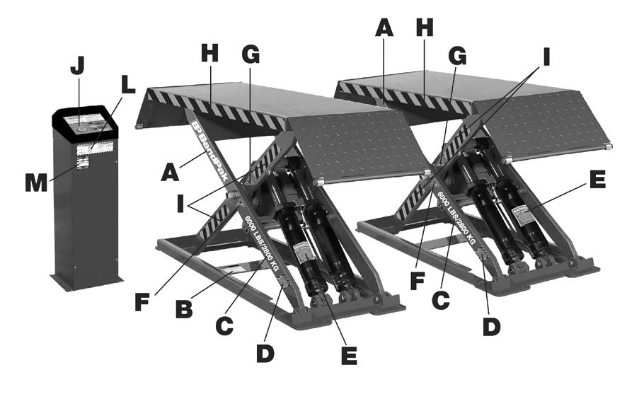
8 This lift should be installed by qualified lift installers only who are familiar with this particular lift model and the requirements thereof. The frame on this lift MUST NOT be twisted, bent or misaligned by un-level floors or improper anchoring. Misalignment may cause damage to the lift. When removing the lift from shipping pallet / angles pay close attention as lift assemblies can slide and can cause injury. Prior to removing any strapping or shipping bolts make sure the lift is held securely by a fork lift or some other heavy lifting device. PARTS INVENTORY Be sure to take a complete inventory of parts prior to beginning installation. MDS-6K Flow Divider Lift Frame 8
9 PARTS INVENTORY Be sure to take a complete inventory of parts prior to beginning installation. MDS-6KF Floor plan/layout dimensions 9
10 Floor plan/layout dimensions *Recommended 1631 *Recommended 1016 MDS-6K MDS-6KF * NOTE: Vehicle jacking points do vary. Check your vehicle jacking point locations before committing to above measurement. Adjust platform width as desired. The rubber contact blocks should be positioned at the middle of the platforms during use for optimum performance. MODEL MDS-6K MDS-6KF Style Mid-Rise Pit Lift / Surface Mount Mid-Rise Pit Lift / Flush Mount Lifting Capacity: 6,000 Lbs / 2722 Kgs. 6,000 Lbs / 2722 Kgs. Lifting Height (Less Lift Blocks) 44 / 1119 mm. 44 / 1119 mm (-4.3/8 for sub-floor) Lifting Height (With Lift Blocks) 45.5 /1158 mm /1158 mm (-4.3/8 for sub-floor) Lift Platform Dimensions 18 x 57 / 457 mm x 1448 mm 18 x 57 / 457 mm x 1448 mm Width Between Platforms 30 / 762 mm 30 / 762 mm Over Width 18.5 / 470mm 18.5 / 470mm Overall Length 79.5 / 2019 mm. 64 / 1626 mm. Lowered Height 4.25 / 105 mm / 105 mm./ (-4.3/8 for sub-floor) Lifting Time 35 Seconds 35 Seconds Motor * VAC/60HZ/ 1Ph VAC/60HZ/ 1Ph. * Special Voltage Available upon request. The design, material and specifications are subject to change without notice. Note: An air supply (minimum: 30 psi / 3 CFM) is required for the safety-lock mechanisms to disengage. It is solely the responsibility of the end-user to provide, install and maintain the air supply. 10
 2.")
11 Fig. 3.1 PIT INSTALLATION FRONT Recommended Pit Width REAR 11 Minimum To Nearest Obstruction 11 Minimum To Nearest Obstruction STEP 3 (Locating Unit) 1. Before selecting an installation site, check for proper clearance and/or obstructions. (See Fig 3.1) 2. Always consult the building engineer before installing this lift to make sure the floor is capable of sustaining the load. 3. After selecting a site, place each unit adjacent to the power unit console. Ensure frames and cylinder ports are facing the same position as shown in the image below. (See Fig. 3.2) 4. An air supply (minimum: 30 psi / 3 CFM) is required for the safety-lock mechanisms to disengage. 5. The hookup work must be carried out by a qualified electrician. 6. Make sure the connection of the phases is correct. Improper electrical hook-up can damage motor and will not be covered under warranty. Cylinders Power Unit Console Fig


 3.")
12 STEP 4 (Locating Power Unit Console) 1. Select a site for the Power Unit Console that permit operators have a full unobstructed view of the lift. Fig /8 2. It is recommended that the Hydraulic Hose and Air Safety Line for the lift be routed through the floor at the base of the Power Unit, so check for routing clearances. Fig. 4.1 Mounting Bolts 7. Secure Power Unit Console to the floor using two 3/8 anchor bolts supplied. 8. Attach Power Unit to Motor Bracket using four 5/16 hex bolts and nyloc nuts supplied. NOTE: Motor must be at least 18 above floor. 90 Degree Hydraulic Fitting Filler Cap Use Hydraulic Oil Only Reservoir Hydraulic Hose 9. Install the Air Safety Valve Z bracket on the upper left mounting hole of the Power Unit Stand. STEP 5 (Power Console / Hose Routing) 1. Remove the front Panel cover on the Power Console. 2. Route the Hydraulic Hoses and the Air Line through the holes at the back of the Power Console. (See Fig. 5.1) 3. Connect the Power Unit (shortest) Hydraulic Hose to the Power Unit Fitting as shown in the image below. It is not necessary to use Teflon tape on JIC fittings. DO NOT OVERTIGHTEN. (See Fig. 5.2) Risk of explosion. DO NOT install the power unit inside or near a paint booth. This equipment has internal arcing or sparking parts which should not be exposed to flammable vapors. Fig. 5.1 Check with building plans prior to drilling any holes in floor. Fig Using the Power Unit Stand as a template, mark the locations of the two anchor bolt holes. 4. Drill two holes 3/8 x 4 deep in concrete floor. 5. Remove all dust from hole. 6. Install Anchors as shown below. (See Fig. 4.2) 12
. Fig. 5.5 Fig. 5.3 A COUPLER FITTING MAY BE REQUIRED TO ADAPT TO YOUR TYPE / SIZE OF AIR SUPPLY LINE.")
 in an area that will")


13 4. Install the two 90 Fittings and one Straight Fitting in the Flow Divider configured as shown. (See Fig. 5.3 ). Fig. 5.5 Fig. 5.3 A COUPLER FITTING MAY BE REQUIRED TO ADAPT TO YOUR TYPE / SIZE OF AIR SUPPLY LINE. Flow Divider Type I STEP 6 (Flow Divider / Hydraulic Hose Installation) 1. For Pit installation, secure the Hydraulic Flow Divider to a permanent wall or fixture (usually below ground) in an area that will allow the Power Hoses (the two hoses that are installed at the lift Cylinders) to be equal length. Flow Divider Type II 5. Install the Flow divider in the bottom of the Power Console. 6. Connect the Power Unit Hose to the Straight Fitting on the Flow Divider and connect both the Powerside and Offside Hydraulic Hoses to the 90 Fittings on the Flow divider as shown. (See Fig. 5.4) Fig. 6.1 Fig. 5.4 power hose more than 12 difference in length may result in unequal lifting of the system. 7. Route the 1/4 Poly-Flow Air Tubing through the hole at the back of the Power Console and connect to the Push Button Air Safety Switch as shown below. (See Fig. 5.5) 13
14 It may be necessary to add hose extensions to accomodate installation. If so, keep the power hoses as close to equal length as possible to provide equal pressure and lifting. 2. Install the 90 Degree Hydraulic Fitting in the pressure port of the Power Unit. The pressure port is covered with a plastic plug. Use teflon tape on pipe fittings ONLY. 3. After the fitting is installed correctly, connect the 140 Hydraulic Hose making sure to not over-tighten. ROUTING HYDRAULIC HOSES Flow Divider Type I IN OUT IN OUT Flow Divider Type II 14
 1.")
15 Check with building plans prior to drilling any holes in floor. (For below ground hose installations a 1-1/4 hole should be drilled through the floor at the base of the Power Unit so the hose can be routed below ground.) 1. Have a certified electrician run the power supply to motor. Refer to the data plate found on the motor for proper power supply and wire size. NOTE: The standard power unit can be run on either 110V or 220V. It is already wired for 110V and equipped with a 3-wire power cord with grounding plug. For optional 220V hook up, follow the wiring instructions as shown on the motor data plate. See electrical data below. Line Voltage Running Amps Circuit Breaker 110/115 V A Fig Connect the other end of the Power Unit Hose to the fitting marked IN on the Flow Divider. (See Fig 6.1) 5. Connect the two remaining equal length Hoses to the Flow Divider. (See Fig 6.1) 3/8 I.D. hydraulic tubing / hose may be used rather than the hose provided as long as it is rated for 3,000 PSI operating pressure with a 12,000 PSI burst. Always use a separate circuit for each lift. Be sure to use proper circuit breakers or time delay fuses to protect circuit. 2. Fill the reservoir with 10 WT. HYDRAULIC OIL OR DEXRON TYPE III ATF, approximately 15 quarts. Make sure the funnel used to fill the tank and power unit is clean. POWER UNIT STEP 7 (Power Unit Installation) Risk of explosion. DO NOT install the power unit inside or near a paint booth. This equipment has internal arcing or sparking parts which should not be exposed to flammable vapors. Motor should NOT be located in a recessed area or below floor level. NEVER expose motor to rain or other damp environments. DAMAGE TO MOTOR CAUSED BY WATER IS NOT COVERED UNDER WARRANTY. Fig The standard power unit for your lift is 110 volt, 60HZ, single phase. All wiring must be performed by a certified electrician only. SEE WIRING INSTRUCTIONS AFFIXED TO MOTOR FOR PROPER WIRING INSTRUCTIONS. 15
16 ALL WIRING MUST BE PERFORMED BY A LICENSED ELECTRICIAN. DO NOT PERFORM ANY MAINTENANCE OR INSTALLATION OF ANY COMPONENTS WITHOUT FIRST ENSURING THAT ELECTRICAL POWER HAS BEEN DISCONNECTED AT THE SOURCE OR PANEL AND CANNOT BE RE-ENERGIZED UNTIL ALL MAINTENANCE AND/OR INSTALLATION PROCEDURES ARE COMPLETED. DO NOT RUN POWER UNIT WITHOUT OIL. DAMAGE TO POWER UNIT PUMP CAN OCCUR. THE POWER UNIT MUST BE KEPT DRY. DAMAGE TO POWER UNIT CAUSED BY WATER OR OTHER LIQUIDS SUCH AS DETERGENTS, ACID ETC., IS NOT COVERED UNDER WARRANTY. OPERATE LIFT ONLY BETWEEN TEMPERATURES OF F. ANY IMPROPER ELECTRICAL INSTALLATION MAY DAMAGE POWER UNIT MOTOR AND RESULTING DAMAGE WILL NOT BE COVERED UNDER WARRANTY. MOTOR CAN NOT RUN ON 50HZ WITHOUT A PHYSICAL CHANGE IN MOTOR. USE A SEPARATE CIRCUIT BREAKER FOR EACH POWER UNIT. PROTECT EACH CIRCUIT WITH TIME DELAY FUSE OR CIRCUIT BREAKER. FOR VOLT, SINGLE PHASE, USE A 25 AMP FUSE. FOR VOLT, THREE PHASE, USE A 20 AMP FUSE. FOR VOLT, THREE PHASE, USE A 15 AMP FUSE. 16
17 STEP 8 (Routing Air Lines Hoses) Connect the Air Safety Cylinders to the Air Safety Valve using the Tee Fitting and the Airline. Route the air line as shown in the image below (See Fig. 8.1), making sure to position the push button air valve with the INLET facing towards the air source and the OUTLET facing towards the lift. A filter/regulator/lubricator must be installed on air supply at lift. Failure to do so will void the warranty. Cut the provided 1/4 air line tubing with a sharp blade to lengths as required. Tubing must be cut square with no burrs. Note: Improper assembly may result in safety lock failure. Connect Air Supply Hose to push air release valve inside Power Unit Console. On opposite side of air release valve connect 1/4 Poly-Flow Air Tubing. Route the 1/4 Poly-Flow Air Tubing through the hole on the Powerside of the Lift Frameconnect it to the Tee Fitting. Connect Air line to each Air Safety Cylinder. Note: An air supply (minimum: 30 psi / 3 CFM) is required for the safety-lock mechanisms to disengage. It is solely the responsibility of the end-user to provide, install and maintain the air supply. AIR PRESSURE SHOULD BE REGULATED TO 125 PSI MAX. ROUTING AIR LINE HOSES Fig

. NOTE: For pre-fab or steel grate floors, check with the building engineer for mounting suggestions.")

18 STEP 9 (Anchoring Lift Assemblies) NOTE: BENDPAK LIFTS ARE SUPPLIED WITH INSTALLATION INSTRUCTIONS AND CONCRETE FASTENERS MEETING THE CRITERIA AS PRESCRIBED BY THE AMERICAN NATIONAL STANDARD "AUTOMOTIVE LIFTS - SAFETY REQUIREMENTS FOR CONSTRUCTION, TESTING, AND VALIDATION" ANSI/ALI ALCTV LIFT BUYERS ARE RESPONSIBLE FOR ANY SPECIAL REGIONAL STRUCTURAL AND/OR SEISMIC ANCHORING REQUIREMENTS SPECIFIED BY ANY OTHER AGENCIES AND/OR CODES SUCH AS THE UNIFORM BUILDING CODE (UBC) AND/OR INTERNATIONAL BUILDING CODE (IBC). NOTE: For pre-fab or steel grate floors, check with the building engineer for mounting suggestions. It may be necessary to install all-thread rods through floor and secure above and below. 1. Before anchoring lift to the floor, make sure the location is satisfactory. Refer to Section Using Compressed air or vacuum, remove all excess dust from holes, then install the anchor bolts. (See Fig 9.3) Fig. 9.3 TAP ANCHOR BOLTS INTO EACH HOLE WITH A HAMMER UNTIL THE WASHER RESTS AGAINST THE BASEPLATE. 5. Tighten the Anchor Bolts 2-3 turn using an open end wrench or manual ratchet only. DO NOT use an impact wrench to tighten concrete anchors. (See Fig 9.4 ) TIGHTEN NUT 3-5 TURNS. DO NOT USE IMPACT WRENCH. 2. Locate the six Anchor Bolt holes in the Lift Base Frame. (See Fig 9.1) NOTE: The lift must be elevated prior to drilling holes. Fig. 9.1 ANCHOR BOLT HOLES LOCATION Fig. 9.4 STEP 10 (Bleeding) mm mm mm mm 3. Using a 3/4 concrete bit, drill six holes on each pad 5 deep using the holes in the frame as a guide. (See Fig 9.2) Fig. 9.2 DRILL HOLE APPROXIMATELY 5 DEEP. 1. Lift must be fully lowered before changing or adding fluid. 2. Raise and lower lift six times. The Cylinders are selfbleeding. After bleeding system, fluid level in power unit reservoir may be down. Add more fluid if necessary to raise lift to full height. It is only necessary to add fluid to Raise lift to full height. 3. It may be necessary to disconnect Hoses at the Cylinders and run the Power Unit to completely bleed the system of air. Consult a trained professional if you are not familiar with this type of bleeding procedure. 4. To pressure test, run lift to full rise and run motor for approximately 3-seconds after lift stops. This will place pressure on the hydraulic system. Stop and check all fittings and hose connections. Tighten or reseal if required. 5. Raise lift only HALF WAY then lower completely at least one dozen times. NOTE: during the initial testing, the lift will descend slowly. This is normal,. It helps to add a payload, no greater than 500 pounds to help speed up the decent during this process. 5. Check all hoses for leaks. Tighten if necessary. 18
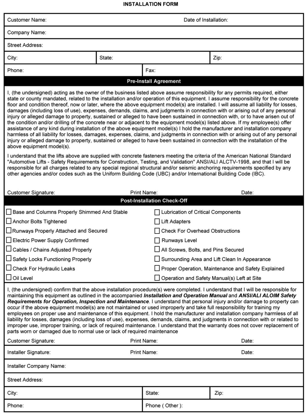
19 STEP 11 (Lift Start Up / Final Adjustments) 1. Make sure the Power Unit Reservoir is full with 6.5 quarts of 10-WT hydraulic oil or Dexron-III automatic transmission fluid. 4. Check all MAIN SAFETY LOCKS to make sure they move freely and fall back to the lock position when released. Lubricate all SAFETY PIVOT points with WD-40 or equal. 2. Test the Power Unit by pressing the push-button switch. If the motor sounds like it is operating properly, raise the lift and check all hose connections for leaks. If the motor gets hot or sounds peculiar, stop and check all electrical connections. 3. Raise lift until THE CYLINDER BOTTOMS OUT AND THE LIFT STOPS. Keep hands and feet clear. Remove hands and feet from any moving parts. Keep feet clear of lift when lowering. Avoid pinch points. Read the entire contents of this manual prior to installation and operation. Failure to follow directions as instructed may cause injury or death. Visually confirm that ALL Primary Safety locks are engaged before entering work area. Suspension components us on this lift are intended to raise and lower lift only and are not meant to be load holding devices. Remain clear of elevated lift unless visual confirmation is made that all primary safety locks are fully engaged and the lift is LOWERED onto the safety locks, Refer to installation /operation manual for proper safety lock procedures and /or further instruction. Lock Bar Release Cam Lock Block SAFETY IN LOCKED POSITION Fig Run the lift up and down a few times to ensure that the locks are engaging uniformly and that the safety release mechanisms are functioning. POST-INSTALLATION CHECK-OFF Columns properly shimmed and stable Anchor Bolts tightened Pivot / Sheave Pins properly attached Electric power supply confirmed Safety Locks functioning properly Check for hydraulic leaks Oil level lubrication of critical components Check for overhead obstructions All Screws, Bolts, and Pins securely fastened Surrounding area clean Operation, Maintenance and Safety Manuals on site. Perform an Operational Test with a typical vehicle ALWAYS ENSURE THAT THE SAFETY IS IN LOCKED POSITION BEFORE ANY ATTEMPT IS MADE TO WORK ON OR NEAR THE VEHICLE. 19
20 STEP 12 (Operation Instructions) OWNER/EMPLOYER RESPONSIBILITIES The Owner/Employer: Shall ensure that lift operators are qualified and that they are trained in the safe use and operation of the lift using the manufacturer s operating instructions; ALI/SM01-1, ALI Lifting it Right safety manual; ALI/ST-90 ALI Safety Tips card; ANSI/ALI ALOIM-2000, American National Standard for Automotive Lifts-Safety Requirements for Operation, Inspection and Maintenance; ALI/WL Series, ALI Uniform Warning Label Decals/Placards; and in the case of frame engaging lifts, ALI/LP-GUIDE, Vehicle Lifting Points/Quick Reference Guide for Frame Engaging Lifts. Shall display the lift manufacturer s operating instructions; ALI/SM 93-1, ALI Lifting It Right safety manual; ALI/ST-90 ALI Safety Tips card; ANSI/ALI AL- OIM-2000, American National Standard for Automotive Lifts-Safety Requirements for Operation, Inspection and Maintenance; and in the case of frame engaging lifts, ALI/ LP-GUIDE, Vehicle Lifting Points/Quick Reference Guide for Frame Engaging Lifts; in a conspicuous location in the lift area convenient to the operator. Shall provide necessary lockout/tagout means for energy sources per ANSI Z (R1993), Safety Requirements for the Lockout/Tagout of Energy Sources, before beginning any lift repairs. Shall not modify the lift in any manner without the prior written consent of the manufacturer. Shall establish procedures to periodically inspect the lift in accordance with the lift manufacturer s instructions or ANSI/ALI ALOIM-2000, American National Standard for Automotive Lifts-Safety Requirements for Operation, Inspection and Maintenance; and The Employer shall ensure that lift inspectors are qualified and that they are adequately trained in the inspection of the lift. Shall establish procedures to periodically maintain the lift in accordance with the lift manufacturer s instructions or ANSI/ALI ALOIM-2000, American National Standard for Automotive Lifts-Safety Requirements for Operation, Inspection and Maintenance; and The Employer shall ensure that lift maintenance personnel are qualified and that they are adequately trained in the maintenance of the lift. Shall maintain the periodic inspection and maintenance records recommended by the manufacturer or ANSI/ALI ALOIM-2000, American National Standard for Automotive Lifts-Safety Requirements for Operation, Inspection and Maintenance. DAILY inspect your lift. Never operate if it malfunctions or if it has broken or damaged parts. Use only qualified lift service personnel and genuine BendPak parts to make repairs. THOROUGHLY train all employees in use and care of lift, using manufacturer s instructions and Lifting It Right and Safety Tips supplied with the lift. LIFT OPERATION SAFETY NEVER overload lift. Capacity of lift is shown on nameplate affixed to the lift. DO NOT stand in front of the vehicle while it is being positioned in lift bay. NEVER allow unauthorized or untrained persons to position vehicle or operate lift. PROHIBIT unauthorized persons from being in shop area while lift is in use. DO NOT permit anyone on lift or inside vehicle when it is either being raised or lowered. ALWAYS keep area around lift free of tools, debris, grease and oil. 20 THE LIFT WAS DESIGNED TO RAISE ONLY PASSENGER CARS AND LIGHT DUTY TRUCKS. MANY FULL-SIZE TRUCKS, SPECIALTY OR MODIFIED VEHICLES CANNOT BE RAISED ON THIS TYPE OF LIFT. CONTACT VEHICLE MANUFACTURER FOR RAISING OR JACKING DETAILS. NEVER USE LIFTING ADAPTERS OTHER THAN THOSE SPECIFICALLY DESIGNED FOR THIS LIFT.
21 ALWAYS load vehicle on lift carefully. Position the lift adapters to contact at the vehicle manufacturer s recommended lift points. Raise lift until adapters contact vehicle. Check adapters for secure contact with vehicle. Raise lift to desired working height. (See Fig.12.1) LIFT OPERATION SAFETY (CONT D) ALWAYS REMOVE tool trays, stands, etc. before lowering lift. WHEN LOWERING THE LIFT PAY CAREFUL ATTENTION THAT ALL PERSONNEL AND OBJECTS ARE KEPT CLEAR. ALWAYS KEEP A VISUAL LINE OF SIGHT ON THE LIFT AT ALL TIMES. ALWAYS MAKE SURE THAT ALL LOCKS ARE DISENGAGED. IF ONE OF THE LOCKS INADVERTENTLY LOCKS UPON DESCENT THE VEHICLE MAY DISMOUNT CAUSING PERSONAL INJURY OR DEATH. DO NOT block open or override self-closing lift controls; they are designed to return to the Off or Neutral position when released. ALWAYS remain clear of lift when raising or lowering vehicles. ALWAYS use safety stands when removing or installing heavy components. DO NOT go under raised vehicle if safety locks are not engaged. Fig ALWAYS RELEASE safety locks before attempting to lower lift. ALWAYS POSITION the lift arms and adapters to provide an unobstructed exit before removing vehicle from lift area. NEVER use the lift to raise just one end of the vehicle Before loading or raising vehicle, be sure all personnel are clear of the lift and surrounding area. Pay careful attention to overhead clearances. TO LOAD THE LIFT VISUALLY CONFIRM THAT ALL PRIMARY SAFETY LOCKS ARE ENGAGED BEFORE ENTERING WORK AREA. SUSPENSION COMPONENTS USED ON THIS LIFT ARE INTENDED TO RAISE AND LOWER LIFT ONLY AND ARE NOT MEANT TO BE LOAD HOLDING DEVICES. REMAIN CLEAR OF ELEVATED LIFT UNLESS VISUAL CONFIRMATION IS MADE THAT ALL PRIMARY SAFETY LOCKS ARE FULLY ENGAGED AND THE LIFT IS LOWERED ONTO THE SAFETY LOCKS, REFER TO INSTALLATION/ OPERATION MANUAL FOR PROPER SAFETY LOCK PROCEDURES AND/OR FURTHER INSTRUCTION. NEVER LEAVE LIFT IN ELEVATED CONDITION unless all Safety Locks are engaged. AVOID excessive rocking of vehicle while on lift. ALWAYS CLEAR AREA if vehicle is in danger of falling. TO AVOID PERSONAL INJURY AND/OR PROPERTY DAMAGE, PERMIT ONLY TRAINED PERSONNEL TO OPERATE LIFT. AFTER REVIEWING THESE INSTRUCTIONS, PRACTICE USING LIFT CONTROLS BY RUNNING THE LIFT THROUGH A FEW UNLOADED CYCLES BEFORE LOADING VEHICLE ON LIFT. ALWAYS LIFT THE VEHICLE USING ALL FOUR ADAPTERS. NEVER RAISE JUST ONE END, ONE CORNER, OR ONE SIDE OF VEHICLE. Before Loading: Lift must be fully lowered and service bay clear of all personnel before the vehicle is brought on lift. 1. Make sure lift is fully lowered position. 2. Drive vehicle over the lift making sure that the centerline of the vehicle is positioned properly over the lift pads. 3. Set parking brake or use wheel chock to hold vehicle in position. 21
22 4. Position any pads underneath the vehicle making sure that they make secure contact with the frame or other recommended lifting point. TO RAISE THE LIFT 1. Some vehicles may have the manufacturer's Service Garage Lift Point locations identified by triangle shape marks on the undercarriage (reference ANSI/SAE J ). Also, there may be a label located on the right front door jamb area showing specific vehicle lift points. TO LOWER THE LIFT 1. Remove all tools or other objects from the lift area. 2. Raise the lift until at least two inches to provide adequate clearance for the safety to operate. 3. Push the Air Safety Release Button and hold. 4. Visually confirm that the safety bar has been raised up off the safety locks. (See Fig. 12.3) 2. Raise the lift by pressing the UP button on the power unit. 3. Raise lift until the vehicles tires clear the floor. 4. Stop and check to make sure the vehicle is secure and the lifting pads are still in contact with the frame. 5. Continue raising until the vehicle is at the desired height. 6. Raise until the safety lock bars drop into position. (See Fig. 12.2) Lock Bar Release Cam Lock Block SAFETY IN UNLOCKED POSITION Fig Lock Bar Fig Push LOWERING valve handle to lower. Note: Both SAFETY LOCK release and LOWERING valve handles must be held down simultaneously to lower lift. Do not override selfclosing lift controls. Release Cam Lock Block SAFETY IN LOCKED POSITION 7. Lower the lift onto the nearest safety lock. YOU MUST RELEASE THE AIR SAFETY BUTTON WHEN LIFT IS 10 INCHES OFF THE GROUND. FAILURE TO DO SO MAY RESULT IN DAMAGE TO THE LIFT S SAFETY COMPONENTS. VISUALLY CONFIRM THAT ALL PRIMARY SAFETY LOCKS ARE ENGAGED BEFORE ENTERING WORK AREA. SUSPENSION COMPONENTS USED ON THIS LIFT ARE INTENDED TO RAISE AND LOWER LIFT ONLY AND ARE NOT MEANT TO BE LOAD HOLDING DEVICES. REMAIN CLEAR OF ELEVATED LIFT UNLESS VISUAL CONFIRMATION IS MADE THAT ALL PRIMARY SAFETY LOCKS ARE FULLY ENGAGED AND THE LIFT IS LOWERED ONTO THE SAFETY LOCKS, REFER TO INSTALLATION/ OPERATION MANUAL FOR PROPER SAFETY LOCK PROCEDURES AND/OR FURTHER INSTRUCTION. 6. Remain clear of lift when lowering vehicle. Observe pinch point warning decals. 7. Continue pressing the Lower Handle to Fully lower the lift. Remove all lifting adapters before driving vehicle away. 8. If lift is not operating properly, DO NOT use until adjustment or repairs are made by qualified lift service personnel. 22
23 MAINTENANCE INSTRUCTIONS Always keep bolts tight. Check periodically. Always keep lift components clean. Always if oil leakage is observed, call local service representative. Always call local service representative if electrical problems develop. Always replace ALL FAULTY PARTS before lift is put back into operation. Daily: Make a visual inspection of ALL MOVING PARTS and check for excessive signs of wear. Daily: Check safety locks to ensure they are in good operating condition. Daily: Inspect lift pads for damage or excessive wear. Replace as required with genuine BendPak parts. Weekly: Check all bolts and pins to ensure proper mounting. Monthly: Lubricate locking latch shafts. Push latch handle several times for oil to penetrate pivot points. Every 3 Months: Check anchor bolt torque. Anchors should be torqued to 90 ft/lbs. Semi-Annually: Check fluid level of lift power unit and refill if required per lift installation instructions. Replace all caution, warning or safety related decals on the lift if unable to read or missing. Reorder labels from BendPak. Refer to ANSI/ALI ALOIM booklet for periodic inspection checklist and maintenance log sheet. SAFE LIFT OPERATION 23
24 SAFE LIFT OPERATION 24

25 SAFE LIFT OPERATION 25


26 MDS-6K & MDS-6KF MODELS LABELS A B C J BendPak_Cylinder_Decal_New.pdf: Material: Clear Adhesive PET Size: 16 W x 3 H Thickness: 2 Mil 6000 LBS/2800 KGPN MDS-6K_Capacity_Label_ pdf: Size: 10 W x 1.5 H! FAILURE TO READ AND UNDERSTAND THE FOLLOWING WARNINGS MAY RESULT IN PERSONAL INJURY AND / OR PROPERTY DAMAGE. Model MDS-6K/6KF (Mid-Rise Scissor Lift) OPERATION INSTRUCTIONS TO RAISE LIFT: Maximum Lifting Capacity 6,000 lbs. / 2722 kg Clear area of personnel and make sure lift is in full lowered position. Drive vehicle over lift making sure center line of the vehicle is positioned properly over lift pads. READ AND UNDERSTAND ENTIRE CONTENTS OF OPERATION MANUAL AND Position lift pads underneath the vehicle making sure that they make secure contact with the WARNINGS BELOW BEFORE OPERATING THIS EQUIPMENT. factory recommended lifting points. 3 Never exceed the rated capacity of the lift Before raising, make sure the weight of the vehicle does not exceed rated capacity of lift. 3 DO NOT operate the lift if any component is found to be defective or worn Push the RAISE button to commence lifting. 3 Never operate lift with any person or equipment below Raise lift until the vehicles tires clear the floor. Stop then check if vehicle is secure and the lifting pads are still in contact with the frame. 3 Always ensure load is centered and stable prior to operating controls Continue raising vehicle to desired height. 3 When lowering the lift pay careful attention that all personnel and objects are kept clear. Raise until the safety lock bars drop into the LOCKED position as described on Fig. A 3 Always keep a visual line of site on the lift during operation Lower the lift until the LOCK BARS rest against the LOCK BLOCKS. 3 Always stand clear of lift when lowering or raising TO LOWER LIFT: 3 Never leave lift in elevated position unless safety lock is engaged in the LOCKED position Clear area before lowering lift. 3 Keep all body parts and objects away from pinch points when lift is in motion Raise the lift until the release cams drop into the UNLOCKED position as described on Fig. B Push the LOWERING button until the lift starts to descend. Stay clear of lift area. 3 Use on level concrete in good condition and free of cracks or other defects Push AIR ASSIST button to increase lowering speed after lift pads leave vehicle undercarriage. 3 Visually confirm safety lock is properly engaged before working on or near lift Fully lower the lift and remove all lifting pads before driving vehicle away.! SAFETY FIRST AIR ASSIST WARNING RAISE LIFT OPERATION LOWER Clear PET material and SHOULD NOT print as Yellow Clear PET material and F D E Product_Data_Label_ New.pdf: CAUTION! Maximum load on scissor lifts should NOT exceed 3,000 pounds per side. Always center the load evenly. NEVER attempt to work on or near a vehicle when it is raised on the scissors unless the safety latches are engaged on each scissor unit. P/N PN PN Caution_Capacity_Scissor_Lift_ pdf: Size: 2.5 W x 2 H WARNING! VERY IMPORTANT TO PROLONG LIFE EXPECTANCY OF CYLINDER SEALS AND PREVENT PREMATURE LEAKAGE AND WEAR, RAISE LIFT TO FULL HEIGHT AT LEAST ONCE A DAY. ALSO, THIS IS AN EFFECTIVE WAY TO BLEED ANY TRAPPED AIR AND MAINTAIN EQUAL LIFTING OF THE SYSTEM. PN PN Scissor_Cylinder_Warning-Red pdf: G B U T T O N PN Lemonwood Dr. Santa Paula, CA TEL: ENGINEERED BY BENDPAK USA MADE IN CHINA MDS-6K_Warning_Label-NEW(B).pdf: Size: 9.5 W x 9.5 H M PN H Lube_Label.pdf: Pinch_Point_Label.pdf: I Hazard_Decal.pdf Size: 32 W x 1.5 H PN Serial_Tag_New _Edited.jpg: Size: 3 W x 3 H L Hazard_Decal.pdf Size: 8 W x 1.5 H DRIVE CAR COMPLETELY OVER LIFT! WARNING ALWAYS ensure that the safety is in LOCKED position before any attempt is made to work on or near the vehicle. SAFETY IN LOCKED POSITION SAFETY IN UNLOCKED POSITION (Release Cam disengaged. (Release Cam and Lock Bar elevated Lock Bar resting against Lock Block.) and clear. Lock Bar disengaged.) Lock Bar Lock Bar NEVER OVERLOAD LIFT Check for 1 minimum clearance between car and lift before raising. PN DO NOT park on or load lift in a fully lowered position or damage may result. Release Cam Lock Block Release Cam Lock Block 26 Warning_Drive_Car_Over pdf: Size: 9 W x 2.75 H PN
27 LABELS POSITIONING 27
28 LIFT WILL NOT RAISE POSSIBLE CAUSE 1. Air in oil, (1,2,8,13) 2. Cylinder binding, (9) 3. Cylinder leaks internally, (9) 4. Motor run backward under pressure, (11) 5. Lowering valve leaks, (3,4,6,10,11) 6. Motor runs backwards, (7,14,11) 7. Pump damaged, (10,11) 8. Pump won t prime, (1,8,13,14,3,12,10,11) 9. Relief valve leaks, (10,11) 10. Voltage to motor incorrect, (7,14,11) Remedy Instruction 1. Check for proper oil level The oil level should be up to the bleed screw in the reservoir with the lift all the way down. 2. Bleed cylinders See Installation Manual 3. Flush- Release valve to get rid of Hold release handle down and start unit allowing possible contamination it to run for 15 seconds. 4. Dirty oil Replace oil with clean Dexron ATF. 5. Tighten all fasteners Tighten fasteners to recommended torques. 6. Check for free movement of release If handle does not move freely, replace bracket or handle assembly. 7. Check motor is wired correctly Compare wiring of motor to electrical diagram on drawing. 8. Oil seal damaged or cocked replace oil seal around pump shaft. 9. See Installation Manual Consult Lift Manufacturer. 10. Replace with new part Replace with new part. 11. Return unit for repair Return unit for repair. 12. Check pump-mounting bolts Bolts should be 15 to 18 ft. lbs. 13. Inlet screen clogged Clean inlet screen or replace. 14. Check wall outlet voltages and wiring make sure unit and wall outlet are wired properly. 28
29 MOTOR WILL NOT RUN POSSIBLE CAUSE 1. Fuse blown, (5,2,1,3,4) 2. Limit switch burned out, (1,2,3,4) 3. Microswitch burned out, (1,2,3,4) 4. Motor burned out, (1,2,3,4,6) 5. Voltage to motor incorrect, (2,1,8) Remedy Instruction 1. Check for correct voltage compare supply voltage with voltage on motor name tag. Check that the wire is sized correctly. N.E.C. table requires AWG 10 for 25 Amps. 2. Check motor is wired correctly compare wiring of motor to electrical diagram on drawing. 3. Don t use extension cords According to N.E.C. : The size of the conductors should be such that the voltage drop would not exceed 3% to the farthest outlet for power Do not run motor at 115 VAC damage to the motor will occur. 4. Replace with new part replace with new part. 5. Reset circuit breaker/fuse reset circuit breaker/fuse. 6. Return unit for repair Return unit for repair. 7. See Installation Manual See Installation Manual. 8. Check wall outlet voltage and wiring Make sure unit and wall outlet is wired properly. Motor must run at 208/230 VAC. LIFT LOWERS SLOWLY OR NOT AT ALL POSSIBLE CAUSE 1. Cylinders binding, (1) 2. Release valve clogged, (5,4,2,3) 3. Pressure fitting too long, (6) Remedy Instruction 1. See Installation Manual Consult Lift Manufacturer. 2. Replace with new part replace with new part. 3. Return for repair Return for repair. 4. Check oil Use clean 10-WT hydraulic oil or Dexron-III automatic transmission fluid only. If ATF is contaminated, replace with clean ATF and clean entire system. 5. Clean release valve wash release valve in solvent and blow out with air. 6. Replace fitting with short thread lead Replace fitting with short thread lead. 29
30 WILL NOT RAISE LOADED LIFT POSSIBLE CAUSE 1. Air in oil, (1,2,3,4) 2. Cylinder binding, (5) 3. Cylinder leaks internally, (5) 4. Lift overloaded, (6,5) 5. Lowering valve leaks, (7,8,1,5,9) 6. Motor runs backwards, (10,12,9) 7. Pump damaged, (5,9) 8. Pump won t prime, (1,2,3,4,5,11,9) 9. Relief valve leaks, (8,5,9) 10. Voltage to motor incorrect, (10,12,5) Remedy Instruction 1. Check oil level The oil level should be up to the bleed screw in the reservoir [with the lift all the way down.] 2. Check/Tighten inlet tubes Replace inlet hose assembly. 3. Oil seal damaged or cocked Replace oil seal and install. 4. Bleed cylinders See Installation Manual. 5. See Installation Manual Consult Lift Manufacturer. 6. Check vehicle weight Compare weight of vehicle to weight limit of the lift. 7. Flush release valve Hold release handle down and start unit allowing it to run for 15 seconds. 8. Replace with new part Replace with new part. 9. Return unit for repair Return unit for repair. 10. Check motor is wired correctly Compare wiring of motor to electrical diagram on power unit drawing. 11. Inlet screen clogged Clean inlet screen or replace. 12. Check wall outlet voltage and wiring make sure unit and wall outlet is wired properly. IMPORTANT If vehicle becomes stranded in the air, follow all operation instructions as shown on pages If after observing that all mechanical locks are released and the lift still fails move following all standard operating procedures, immediately stop using the lift and contact factory or factory approved service center for further instructions. 30
 Remedy Instruction 1. Check oil level....................................the oil level should be up to the bleed screw in the reservoir with the lift all the way down. 2.")

31 LIFT WILL NOT STAY UP POSSIBLE CAUSE 1. Air in oil, (1,2,3) 2. Check valve leaks, (6) 3. Cylinders leak internally, (7) 4. Lowering valve leaks, (4,5,1,7,6) 5. Leaking fittings, (8) Remedy Instruction 1. Check oil level the oil level should be up to the bleed screw in the reservoir with the lift all the way down. 2. Oil seal damaged and cocked Replace oil seal around pump shaft. 3. Bleed cylinder Refer to Installation Manual. 4. Flush release valve Hold release handle down and start unit allowing it to run for 15 seconds. 5. Replace with new valve Replace with new valve. 6. Return unit for repair Return unit for repair. 7. See Installation Manual Consult Lift Manufacturer. 8. Check complete hydraulic system for leaks tighten all hydraulics fittings and inspect all hoses. Torque Recommendations VALUES ARE STATED IN FOOT POUNDS (ft-lb) Bolt Size (SAE) Bolt Size (Metric) SAE SAE Grade 5 SAE Grade 8 SOCKET HEAD CAP SCREW CLASS 4.8 CLASS 8.8 CLASS 10.9 CLASS /4-20 M6 x /16-18 M8 x /8-16 M10 x / /2-13 M12 x /16-12 M14 x /8-11 M16 x /4-10 M18 x /8-9 M22 x /4 Anchor Bolts 75 MIN 110 MAX 31
32 32
Models PR-12F PR-12C PR-15C SURFACE MOUNTED TWO-POST LIFTS INSTALLATION AND OPERATION MANUAL
 Forward this manual to all operators. Failure to operate this equipment as directed may cause injury. INSTALLATION AND OPERATION MANUAL SURFACE MOUNTED TWO-POST LIFTS Models PR-12F PR-12C PR-15C Keep this
MODEL QMR6 PORTABLE MID-RISE LIFT 6,000 lb Capacity 1500 lb Per Arm INSTALLATION, OPERATION AND MAINTENANCE MANUAL
 MODEL QMR6 PORTABLE MID-RISE LIFT 6,000 lb Capacity 1500 lb Per Arm INSTALLATION, OPERATION AND MAINTENANCE MANUAL IMPORTANT!!! READ THIS MANUAL COMPLETELY BEFORE INSTALLING OR OPERATING THE LIFT 200 CABEL
INSTALLATION AND OPERATION MANUAL 1,500 POUND CAPACITY MOTORCYCLE / ATV LIFT Model: RML-1500XL
 PLEASE READ THE ENTIRE CONTENTS OF THIS MANUAL PRIOR TO INSTALLATION AND OPERATION. BY PROCEEDING YOU AGREE THAT YOU FULLY UNDERSTAND AND COMPREHEND THE FULL CONTENTS OF THIS MANUAL. FORWARD THIS MANUAL
ATTENTION. 1. Do not attempt to use the power unit to extend your cylinder. This must be done manually.
 NSS8XLT Installation Manual ATTENTION By following the instructions in this manual you can save yourself much time, frustration and money. The installation of your lift will take 4-5 hours. Do not rush.
Models: SURFACE MOUNTED FOUR-POST LIFTS INSTALLATION AND OPERATION MANUAL
 Forward this manual to all operators. Failure to operate this equipment as directed may cause injury. INSTALLATION AND OPERATION MANUAL SURFACE MOUNTED FOUR-POST LIFTS Models: FL-18 BP-18 BP-27/ BP-27A
INSTALLATION AND OPERATION MANUAL 14,000 POUND CAPACITY COMMERCIAL GRADE FOUR-POST LIFTS
 INSTALLATION AND OPERATION MANUAL 14,000 POUND CAPACITY COMMERCIAL GRADE FOUR-POST LIFTS MODELS: HDS-14 HDS-14X PLEASE READ THE ENTIRE CONTENTS OF THIS MANUAL PRIOR TO INSTALLATION AND OPERATION. BY PROCEEDING
Model PL-7 / PL-7X AUTOMOBILE STACKER INSTALLATION AND OPERATION MANUAL
 Forward this manual to all operators. Failure to operate this equipment as directed may cause injury. AUTOMOBILE STACKER INSTALLATION AND OPERATION MANUAL Model PL-7 / PL-7X Keep this operation manual
GLO-8000 SERIES (GLO-8000 & GLO-8000XLT)
") GLO-8000 SERIES (GLO-8000 & GLO-8000XLT) 8,000 LBS. CAPACITY FOUR-POST STORAGE LIFT INSTALLATION & OPERATION MANUAL SERIAL NUMBER: INSTALLATION DATE: EAGLE EQUIPMENT 1-800-336-2776 REV2011 03.0 BD SHIPPING
GLO-8000 SERIES (GLO-8000 & GLO-8000XLT) 8,000 LBS. CAPACITY FOUR-POST STORAGE LIFT INSTALLATION & OPERATION MANUAL SERIAL NUMBER: INSTALLATION DATE: EAGLE EQUIPMENT 1-800-336-2776 REV2011 03.0 BD SHIPPING
Installation and Operation Manual
 1645 Lemonwood Dr. Santa Paula, CA 93060 USA Toll Free: 1 (800) 253-2363 Tel: 1 (805) 933-9970 rangerproducts.com Ranger Floor Jack Installation and Operation Manual Manual Revision B July 2017 Manual
2-Post Lift Operations and Maintenance Manual
 2-Post Lift Operations and Maintenance Manual Table Of Contents Safety Instructions... 2 Owner/Employer Responsibilities / Operating Conditions... 3 Operating Instructions... 4 Maintenance Instructions...
GLO-7000 SERIES (GLO-7000 & GLO-7000XLT)
") GLO-7000 SERIES (GLO-7000 & GLO-7000XLT) 7,000 LBS. CAPACITY FOUR-POST STORAGE LIFT (BLUE) INSTALLATION & OPERATION MANUAL SERIAL NUMBER: INSTALLATION DATE: EAGLE EQUIPMENT 1-800-336-2776 (STANDARD) SHIPPING
GLO-7000 SERIES (GLO-7000 & GLO-7000XLT) 7,000 LBS. CAPACITY FOUR-POST STORAGE LIFT (BLUE) INSTALLATION & OPERATION MANUAL SERIAL NUMBER: INSTALLATION DATE: EAGLE EQUIPMENT 1-800-336-2776 (STANDARD) SHIPPING
INSTALLATION AND OPERATION MANUAL 9,000 POUND CAPACITY COMMERCIAL GRADE FOUR-POST LIFTS
 PLEASE READ THE ENTIRE CONTENTS OF THIS MANUAL PRIOR TO INSTALLATION AND OPERATION. BY PROCEEDING YOU AGREE THAT YOU FULLY UNDERSTAND AND COMPREHEND THE FULL CONTENTS OF THIS MANUAL. FORWARD THIS MANUAL
INSTALLATION AND OPERATION MANUAL
 PLEASE READ THE ENTIRE CONTENTS OF THIS MANUAL PRIOR TO INSTALLATION AND OPERATION. BY PROCEEDING YOU AGREE THAT YOU FULLY UNDERSTAND AND COMPREHEND THE FULL CONTENTS OF THIS MANUAL. FORWARD THIS MANUAL
OPERATION AND ASSEMBLY MANUAL HIGH JACK STANDS Models: RJS-1T RJS-1TF RJS-2TH
 PLEASE READ THE ENTIRE CONTENTS OF THIS MANUAL PRIOR TO INSTALLATION AND OPERATION. BY PROCEEDING YOU AGREE THAT YOU FULLY UNDERSTAND AND COMPREHEND THE FULL CONTENTS OF THIS MANUAL. FORWARD THIS MANUAL
ATO7 (100 Series Lifts)
") O PE ATO7 (100 Series Lifts) Capacity 7000 lbs. (3181 kg) 1750 lbs. (795.25 kg) per arm R A TI O N & M AI N TE N A N N CE Table Of Contents Safety Instructions... 2 Owner/Employer Responsibilities / Operating
O PE ATO7 (100 Series Lifts) Capacity 7000 lbs. (3181 kg) 1750 lbs. (795.25 kg) per arm R A TI O N & M AI N TE N A N N CE Table Of Contents Safety Instructions... 2 Owner/Employer Responsibilities / Operating
Installation Instructions X-Force UTV Lift (000 Series) Capacity 2,275 lbs (1,035 kg)
 Capacity 2,275 lbs (1,035 kg)") Installation Instructions X-Force UTV Lift (000 Series) Capacity 2,275 lbs (1,035 kg) Read entire manual before assembling, installing, operating, or servicing this equipment. LP20640 IN20793 September
Installation Instructions X-Force UTV Lift (000 Series) Capacity 2,275 lbs (1,035 kg) Read entire manual before assembling, installing, operating, or servicing this equipment. LP20640 IN20793 September
SPOA10NB, SPOA10, SPO10 ( Series Lifts) SPOA7, SPOA9, SPO9 (500 Series Lifts)
 SPOA7, SPOA9, SPO9 (500 Series Lifts)") O PE SPOA10NB, SPOA10, SPO10 (200-700 Series Lifts) SPOA7, SPOA9, SPO9 (500 Series Lifts) SPOA7 Capacity 7,000 lbs. SPOA9, SPO9 Capacity 9,000 lbs. SPOA10NB, SPOA10, SPO10 Capacity 10,000 lbs. R A TI O
O PE SPOA10NB, SPOA10, SPO10 (200-700 Series Lifts) SPOA7, SPOA9, SPO9 (500 Series Lifts) SPOA7 Capacity 7,000 lbs. SPOA9, SPO9 Capacity 9,000 lbs. SPOA10NB, SPOA10, SPO10 Capacity 10,000 lbs. R A TI O
Drop Tail Motorcycle Lift 1,000 lbs. capacity Installation, Safety, Operation, Maintenance
 Drop Tail Motorcycle Lift 1,000 lbs. capacity Installation, Safety, Operation, Maintenance Entire contents 2009 by Direct Lift. All rights reserved. IN50012 CO7338.1 Rev. B 03/30/2009 Inspection upon receipt
Cargolift 85 Pv Repair. Cargolift 90 Sa Standard. Cargolift 120 Saav Jumbo. Cargolift 120 F Drive-on IMPORTANT
 Installation, Operation and Maintenance Manual For Cargolift 85 Pv Repair Cargolift 90 Sa Standard Cargolift 120 Saav Jumbo Cargolift 120 F Drive-on IMPORTANT Read this manual throughoutly before installing,
Installation and Operation Manual
 1645 Lemonwood Dr. Santa Paula, CA 93060 USA Toll Free 1 (800) 253-2363 Tel: 1 (805) 933-9970 rangerproducts.com High-Speed Oil Filter Crusher Installation and Operation Manual Manual Revision C May 2017
Installation and Operation Manual
 1645 Lemonwood Dr. Santa Paula, CA 93060 USA Toll Free: (800) 253-2363 Telephone: (805) 933-9970 bendpak.com GrandPrix Two-Post Lifts Installation and Operation Manual Manual Revision C2 August 2018 Manual
Installation and Operation Manual
 1645 Lemonwood Dr. Santa Paula, CA, 93060 USA Toll Free: (800) 253-2363 Tel: (805) 933-9970 bendpak.com Full-Rise Scissor Lift Installation and Operation Manual Manual P/N 5900010 Manual Revision A October
Two Post Surface Mounted Lift 12,000 LBS. CAPACITY 3000 LBS. PER ARM
 INSTALLATION, OPERATION & MAINTENANCE MANUAL Two Post Surface Mounted Lift MODEL EELR537A 12,000 LBS. CAPACITY 3000 LBS. PER ARM Snap-On Equipment 309 Exchange Avenue, Conway, Arkansas, 72032 Tel: 501-450-1500
Model Q4P12E and Q4P12X
 INSTALLATION, OPERATION & MAINTENANCE MANUAL Four Post Surface Mounted Lift Model Q4P2E and Q4P2X Closed Front (2,000 lb Capacity) 200 Cabel Street, P.O. Box 3944 Louisville, Kentucky 4020-3944 Email:sales@Qualitylifts.com
Motorcycle Lift 1,000 lbs. capacity Installation, Safety, Operation, Maintenance
 Motorcycle Lift 1,000 lbs. capacity Installation, Safety, Operation, Maintenance Entire contents 2008 by RL Consolidated, Inc. All rights reserved. 994358 CO7297 Rev. F 12/17/2008 Inspection upon receipt
Challenger Lifts, Inc. MODEL 12000
 Challenger Lifts, Inc. MODEL 12000 TWO POST SURFACE MOUNTED LIFT OPERATION, INSTALLATION & MAINTENANCE MANUAL IMPORTANT READ THIS MANUAL COMPLETELY BEFORE INSTALLING OR OPERATING THE LIFT 200 CABEL STREET,
INSTALLATION, OPERATION & MAINTENANCE MANUAL
 INSTALLATION, OPERATION & MAINTENANCE MANUAL Two Post Surface Mounted Lift MODEL X10 10,000 LBS. CAPACITY 2500 LBS. PER ARM 200 Cabel Street, P.O. Box 3944 Louisville, Kentucky 40201-3944 Email:sales@challengerlifts.com
Model Q4P12E and Q4P12X
 INSTALLATION, OPERATION & MAINTENANCE MANUAL Four Post Surface Mounted Lift Model Q4P2E and Q4P2X Closed Front (2,000 lb Capacity) 200 Cabel Street, P.O. Box 3972 Louisville, Kentucky 4020-3972 Email:sales@Qualitylifts.com
Installation and Operation Manual
 1645 Lemonwood Dr. Santa Paula, CA, 93060 USA Toll Free: 1 (800) 253-2363 Tel: 1 (805) 933-9970 bendpak.com RBJ Series of Rolling Bridge Jacks Installation and Operation Manual Manual Revision B Released
Two Post Surface Mounted Lift 12,000 LBS. CAPACITY 3000 LBS. PER ARM
 INSTALLATION, OPERATION & MAINTENANCE MANUAL Two Post Surface Mounted Lift MODEL Q12 12,000 LBS. CAPACITY 3000 LBS. PER ARM 200 Cabel Street, P.O. Box 3944, Louisville, Kentucky 40206 Email:sales@qualitylifts.com
Challenger Lifts, Inc. MODELS & 18000
 Challenger Lifts, Inc. MODELS 15000 & 18000 TWO POST SURFACE MOUNTED LIFT OPERATION, INSTALLATION & MAINTENANCE MANUAL IMPORTANT READ THIS MANUAL COMPLETELY BEFORE INSTALLING OR OPERATING THE LIFT 200
Installation and Operation Manual
 1645 Lemonwood Dr. Santa Paula, CA, 93060 USA Toll Free (800) 253-2363 Tel: (805) 933-9970 bendpak.com Low-Rise Pit Lift Installation and Operation Manual Manual P/N 5900022 Manual Revision A3 September
INSTALLATION AND OPERATION MANUAL Low Profile Long Frame Floor Jack Model: RFJ-3000LPF REV B
 PLEASE READ THE ENTIRE CONTENTS OF THIS MANUAL PRIOR TO INSTALLATION AND OPERATION. BY PROCEEDING YOU AGREE THAT YOU FULLY UNDERSTAND AND COMPREHEND THE FULL CONTENTS OF THIS MANUAL. FORWARD THIS MANUAL
MODEL QFP09. Two Post Surface Mounted Lift. Installation, Operation & Maintenance Manual. Office / Fax
 Installation, Operation & Maintenance Manual Two Post Surface Mounted Lift MODEL QFP09 9,000 LBS. CAPACITY 2,250 LBS. PER ARM 200 Cabel Street, P.O. Box 3972 Louisville, Kentucky 40201-3972 Email:sales@qualitylifts.com
Installation and Operation Manual
 1645 Lemonwood Dr. Santa Paula, CA 93060 USA Toll Free: (800) 253-2363 Tel: (805) 933-9970 bendpak.com Four-Post Alignment Lifts Installation and Operation Manual Manual Revision F3 April 2018 Manual P/N
SCISSOR LIFT Model MR6K-38 /161108A 6,000lb Capacity Operation Manual
 SCISSOR LIFT Model MR6K-38 /161108A 6,000lb Capacity Operation Manual (Version A) 2009. Apr. CONTENT 1. Safety Note, Caution and Warning Important Information Safety Instructions 2. Technical Manual Product
MaxJax User Manual CAUTION
 MaxJax User Manual Revision F (4/12/14) PLEASE READ THE ENTIRE CONTENTS OF THIS MANUAL PRIOR TO INSTALLATION AND OPERATION. BY PROCEEDING, YOU AGREE THAT YOU FULLY UNDERSTAND AND COMPREHEND THE FULL CON-
Two Post Surface Mounted Lift 10,000 LBS. CAPACITY 2500 LBS. PER ARM
 INSTALLATION, OPERATION & MAINTENANCE MANUAL Two Post Surface Mounted Lift MODEL LE10 10,000 LBS. CAPACITY 2500 LBS. PER ARM 2311 South Park Rd Louisville, Kentucky 40219 Email:sales@challengerlifts.com
Installation Instructions Capacity 10,000 lbs. (100 Series Lift)
") Installation Instructions Capacity 10,000 lbs. (100 Series Lift) IMPORTANT Reference ANSI/ALI ALIS, Safety Requirements for Installation and Service of Automotive Lifts before installing lift. OPERATING
Installation Instructions Capacity 10,000 lbs. (100 Series Lift) IMPORTANT Reference ANSI/ALI ALIS, Safety Requirements for Installation and Service of Automotive Lifts before installing lift. OPERATING
INSTALLATION, OPERATION & MAINTENANCE MANUAL
 INSTALLATION, OPERATION & MAINTENANCE MANUAL Four Post Surface Mounted Lift Model 4P14EFX and 4P14XFX Closed Front (14,000 lb Capacity) 200 Cabel Street, P.O. Box 3944 Louisville, Kentucky 40201-3944 Email:sales@challengerlifts.com
SHIPPING DAMAGE CLAIMS
 INSTRUCTION MANUAL ADMIRAL 9000 SERIES Revision B 3-2011 pn# 199822 PLEASE READ THE ENTIRE CONTENTS OF THIS MANUAL PRIOR TO INSTALLATION AND OPERATION. BY PROCEEDING, YOU AGREE THAT YOU FULLY UNDERSTAND
1000-lb Hydraulic Truck Crane
 1000-lb Hydraulic Truck Crane Owner s Manual WARNING: Read carefully and understand all ASSEMBLY AND OPERATION INSTRUCTIONS before operating. Failure to follow the safety rules and other basic safety precautions
Installation and Operation Manual
 1645 Lemonwood Dr. Santa Paula, CA 93060 USA Toll Free: (800) 253-2363 Tel: (805) 933-9970 bendpak.com Double- and Triple-Wide Parking Lifts Installation and Operation Manual Manual Revision A October
MODEL Two Post Surface Mounted Lift. Office / Fax Installation, Operation & Maintenance Manual
 Installation, Operation & Maintenance Manual Two Post Surface Mounted Lift MODEL 15000 15,000 LB CAPACITY - 3750 LB PER ARM MODEL 18000 18,000 LB CAPACITY 4500 LB PER ARM 200 Cabel Street, P.O. Box 3944
BLAZER 9000 LUBE LIFT OPERATOR AND PARTS MANUAL
 BLAZER 9000 LUBE LIFT OPERATOR AND PARTS MANUAL Blazer 9000 Lube Lift Operator s Manual Note: Instructions must be read thoroughly before installing, operating, or maintaining the lift. Devon Lube Center
60 Watt Industrial LED Low Bay Light
 60 Watt Industrial LED Low Bay Light Owner s Manual WARNING: Read carefully and understand all ASSEMBLY AND OPERATION INSTRUCTIONS before operating. Failure to follow the safety rules and other basic safety
Read this entire manual before operation begins.
 Read this entire manual before operation begins. Record below the following information which is located on the serial number data plate. Serial No. Model No. Date of Installation Contents Specifications.............
INSTALLATION AND OPERATION MANUAL
 AIR-HYDRAULIC ROLLING JACKBEAM CAPACITY: 5000 LBS. MODELS: EELR503A INSTALLATION AND OPERATION MANUAL READ ALL INSTRUCTIONS THOROUGHLY BEFORE INSTALLING, OPERATING, SERVICING, OR MAINTAINING THE LIFT.
SAFETY RULES SPECIFICATIONS READ ALL INSTRUCTIONS BEFORE OPERATING SAVE THESE INSTRUCTIONS
 READ ALL INSTRUCTIONS BEFORE OPERATING SAVE THESE INSTRUCTIONS Thank you for purchasing 7" Polisher. Before attempting to operate your new Polisher please read these instructions thoroughly. You will need
4400-Lb. Capacity Pallet Jack
 Read carefully and understand all ASSEMBLY AND OPERATION INSTRUCTIONS before operating. Failure to follow the safety rules and other basic safety precautions may result in serious personal injury. Item#
3-Pt. Quick Hitch. Owner s Manual
 3-Pt. Quick Hitch Owner s Manual WARNING: Read carefully and understand all ASSEMBLY AND OPERATION INSTRUCTIONS before operating. Failure to follow the safety rules and other basic safety precautions may
OPERATOR PROTECTIVE EQUIPMENT. Owner s Responsibility
 CONGRATULATIONS! You have just made the first step toward making your tire changing chores much easier! This DAA Assist Arm assembly guide will help you to assemble and install your new DAA Assist Arm
INSTALLATION AND OPERATION MANUAL Aluminium Racing Jack Model: RFJ-3000AL
 PLEASE READ THE ENTIRE CONTENTS OF THIS MANUAL PRIOR TO INSTALLATION AND OPERATION. BY PROCEEDING YOU AGREE THAT YOU FULLY UNDERSTAND AND COMPREHEND THE FULL CONTENTS OF THIS MANUAL. FORWARD THIS MANUAL
SL210i/SL212i/SL19i. Table Of Contents
 SL210i/SL212i/SL19i (700 Series) SL19i Capacity 9,000 lbs. SL210i Fixed Pad Capacity 9,000 lbs. SL210i Capacity 10,000 lbs. SL212i Capacity 12,000 lbs. Table Of Contents Owner/Employer Responsibilities...
Air Curtain. Installation, Operating and Maintenance Instructions
 Installation, Operating and Maintenance Instructions Save this manual for future reference. Air Curtain Model Numbers: ES026, ES036, ES042, ES048, ES060, ES072 READ THIS OWNER S MANUAL CAREFULLY BEFORE
INSTALLATION AND OPERATION MANUAL
 Tire Vulcanizer Model: RV80L VER A PLEASE READ THE ENTIRE CONTENTS OF THIS MANUAL PRIOR TO INSTALLATION AND OPERATION. BY PROCEEDING YOU AGREE THAT YOU FULLY UNDERSTAND AND COMPREHEND THE FULL CONTENTS
Installation, Operation & Maintenance Manual. Four Post Surface Mounted Lift. Model Open Front (15,000 lb Capacity)
") Installation, Operation & Maintenance Manual Four Post Surface Mounted Lift Model 405 Open Front (5,000 lb Capacity) 23 South Park Rd Louisville, Kentucky 40206 Email:sales@challengerlifts.com Web site:www.challengerlifts.com
Installation, Operation & Maintenance Manual Four Post Surface Mounted Lift Model 405 Open Front (5,000 lb Capacity) 23 South Park Rd Louisville, Kentucky 40206 Email:sales@challengerlifts.com Web site:www.challengerlifts.com
It is the shop owner's responsibility to train all operators in lift operation and safety.
 2 Your new lift will provide years of dependable service if installed, operated and maintained properly. Read and be prepared to follow all safety, installation, operation, and maintenance instructions
Model OE Four Post Surface Mounted Lift. Office / Fax IMPORTANT: READ THIS MANUAL COMPLETELY BEFORE
 Four Post Surface Mounted Lift Model OE-40000 Open Front (,000 lb Capacity) 0 Cabel Street, P.O. Box 3944 Louisville, Kentucky 40-3944 Email:sales@challengerlifts.com Web site:www.challengerlifts.com Office
Models Q4P07. Four Post Surface Mounted Lift. Installation, Operation & Maintenance Manual IMPORTANT: READ THIS MANUAL COMPLETELY BEFORE
 Installation, Operation & Maintenance Manual Four Post Surface Mounted Lift Models Q4P07 (7,000 lb Capacity) 200 Cabel Street, P.O. Box 3972, Louisville, Kentucky 40201-3972 Email:sales@qualitylifts.com
1½ TON ALUMINUM / STEEL RACING JACK Rated Capacity 3,000-lb MODEL# T815016LT
 Operator s Instruction Manual 1½ TON ALUMINUM / STEEL RACING JACK Rated Capacity 3,000-lb MODEL# T815016LT This is the Safety Alert Symbol. It is used to alert you to potential personal injury hazards.
Models Q4P09H & Q4P09X
 Installation, Operation & Maintenance Manual Four Post Surface Mounted Lift Models Q4P09H & Q4P09X (9,000 lb Capacity) 200 Cabel Street, P.O. Box 3944 Louisville, Kentucky 40201-3944 Email:sales@qualitylifts.com
ATD2P11BS. Two-Post Clear Floor Bi-Symmetric Automotive Lift. Installation & Operation Manual. 11,000 lbs. Capacity. (2,750 lbs.
 Two-Post Clear Floor Bi-Symmetric Automotive Lift 11,000 lbs. Capacity (2,750 lbs. Max per Arm) Installation & Operation Manual 1. Safety Information 1.1 Note, Caution and Warning 1.2 Important Information
TWO POST LIFT INSTALLATION AND OWNERS MANUAL
 TWO POST LIFT INSTALLATION AND OWNERS MANUAL DP15, DP15-2 Capacity 15,000 lbs. 1. TABLE OF CONTENTS 2. Important Information.. 2 3. Section 1 Owner s Manual Safety Instructions... 3 Monthly Maintenance...
150-Lb. Drywall and Panel Hoist
 150-Lb. Drywall and Panel Hoist Owner s Manual WARNING: Read carefully and understand all ASSEMBLY AND OPERATION INSTRUCTIONS before operating. Failure to follow the safety rules and other basic safety
Drop Tail Motorcycle Lift 1,000 lbs. capacity Installation, Safety, Operation, Maintenance
 Drop Tail Motorcycle Lift 1,000 lbs. capacity Installation, Safety, Operation, Maintenance Entire contents 2011 by Vehicle Service Group. All rights reserved. IN50012 CO7932 Rev. C 04/20/2011 Inspection
INSTALLATION AND OPERATION MANUAL
 PLEASE READ THE ENTIRE CONTENTS OF THIS MANUAL PRIOR TO INSTALLATION AND OPERATION. BY PROCEEDING YOU AGREE THAT YOU FULLY UNDERSTAND AND COMPREHEND THE FULL CONTENTS OF THIS MANUAL. FORWARD THIS MANUAL
Read this entire manual before operation begins.
 Read this entire manual before operation begins. Record below the following information which is located on the serial number data plate. Serial No. Model No. Date of Installation Contents Specifications.............
Sawhorse with Chainsaw Holder
 Sawhorse with Chainsaw Holder Owner s Manual Chainsaw not included. WARNING: Read carefully and understand all ASSEMBLY AND OPERATION INSTRUCTIONS before operating. Failure to follow the safety rules and
Air-Operated Waste Oil Drainer
 Air-Operated Waste Oil Drainer 20-Gallon Tank Owner s Manual WARNING: Read carefully and understand all ASSEMBLY AND OPERATION INSTRUCTIONS before operating. Failure to follow the safety rules and other
Hydraulic Bead Breaker Kit
 Hydraulic Bead Breaker Kit Owner s Manual WARNING: Read carefully and understand all ASSEMBLY AND OPERATION INSTRUCTIONS before operating. Failure to follow the safety rules and other basic safety precautions
Angle Grinder Holder
 Angle Grinder Holder Owner s Manual WARNING: Read carefully and understand all ASSEMBLY AND OPERATION INSTRUCTIONS before operating. Failure to follow the safety rules and other basic safety precautions
INSTALLATION AND OPERATION MANUAL
 TRANSMISSION JACKS MODELS: RTJ-1 RTJ-660 RTJ-1100 RTJ-3000 PLEASE READ THE ENTIRE CONTENTS OF THIS MANUAL PRIOR TO INSTALLATION AND OPERATION. BY PROCEEDING YOU AGREE THAT YOU FULLY UNDERSTAND AND COMPREHEND
2000-lb Hand Winch Truck Crane
 2000-lb Hand Winch Truck Crane Owner s Manual WARNING: Read carefully and understand all ASSEMBLY AND OPERATION INSTRUCTIONS before operating. Failure to follow the safety rules and other basic safety
4400-Lb. Capacity Extra-Long Pallet Jack
 4400-Lb. Capacity Extra-Long Pallet Jack Owner s Manual WARNING: Read carefully and understand all ASSEMBLY AND OPERATION INSTRUCTIONS before operating. Failure to follow the safety rules and other basic
Lifting height 5.5" - 72" with adapters " Height overall 165" Width between columns 122" Drive through 109" Width overall 151.
 Model Number TP12KC-D Capacity 12,000 lbs. Lifting height 5.5" - 72" with adapters 79.625" Height overall 165" Width between columns 122" Drive through 109" Width overall 151.125" Arm extension 37.5" -
TXJ0500/RR500 1,000-lbs. Truck Bed Roller Dolly
 OWNER S MANUAL TXJ0500/RR500 1,000-lbs. Truck Bed Roller Dolly WARNING: Questions, problems, missing parts? Before returning to your retailer, call our customer service department at 1-888-448-6746, 8
Heavy-Duty Drywall Dolly Cart
 Heavy-Duty Drywall Dolly Cart Owner s Manual WARNING: Read carefully and understand all ASSEMBLY AND OPERATION INSTRUCTIONS before operating. Failure to follow the safety rules and other basic safety precautions
Parallel Lift Rack MODEL RM
 Form 4401T, 09-03 Supersedes Form 4401T, 10-00 OPERATION INSTRUCTIONS Parallel Lift Rack MODEL RM Copyright 1998-2003 Hunter Engineering Company Contents 1. For Your Safety... 1 1.1 Warning/Instruction
Installation Instructions Capacity 10,000 lbs. DP10 (200 Series Lift)
") Installation Instructions Capacity 10,000 lbs. DP10 (200 Series Lift) IMPORTANT Reference ANSI/ALI ALIS, Safety Requirements for Installation and Service of Automotive Lifts before installing lift. OPERATING
Installation Instructions Capacity 10,000 lbs. DP10 (200 Series Lift) IMPORTANT Reference ANSI/ALI ALIS, Safety Requirements for Installation and Service of Automotive Lifts before installing lift. OPERATING
Installation, Operation & Maintenance Manual. Surface Mounted Lift 10,000 LBS. CAPACITY 2500 LBS. PER ARM
 Installation, Operation & Maintenance Manual VersymmetricTM Two Post Surface Mounted Lift MODEL CL10 10,000 LBS. CAPACITY 2500 LBS. PER ARM 200 Cabel Street, P.O. Box 3944 Louisville, Kentucky 40201-3944
If facility voltage is different, refer to set-up instructions. IMPORTANT This lift is wired and adjusted to operate at 230 volts.
 MODEL 40/50K Installation And Owner s Manual (000Series) Capacity 40,000 lbs. (20,000 lbs. per axle) Capacity 50,000 lbs. (25,000 lbs. per axle) Four Post Surface Mounted Lift IMPORTANT This lift is wired
Heavy-Duty Sawhorse. Owner s Manual
 Heavy-Duty Sawhorse Owner s Manual WARNING: Read carefully and understand all ASSEMBLY AND OPERATION INSTRUCTIONS before operating. Failure to follow the safety rules and other basic safety precautions
110 Volt/12 Volt Portable Inflator
 110 Volt/12 Volt Portable Inflator Owner s Manual WARNING: Read carefully and understand all ASSEMBLY AND OPERATION INSTRUCTIONS before operating. Failure to follow the safety rules and other basic safety
QUICKJACK WARNING INSTALLATION AND OPERATION MANUAL MODELS: 3,500 / 5,000 / 7,000 LB. CAPACITY (1.588 / / 3.
 ! WARNING IMPORTANT SAFETY INSTRUCTIONS SAVE THESE INSTRUCTIONS PLEASE READ THE ENTIRE CONTENTS OF THIS MANUAL PRIOR TO INSTALLATION AND OPERATION. BY PROCEEDING WITH JACK INSTALLATION AND OPERATION YOU
Adjustable Steel Welding Table
 Adjustable Steel Welding Table Owner s Manual WARNING: Read carefully and understand all ASSEMBLY AND OPERATION INSTRUCTIONS before operating. Failure to follow the safety rules and other basic safety
MODEL CL10. Versymmetric Two Post. Surface Mounted Lift. Installation, Operation & Maintenance Manual
 Installation, Operation & Maintenance Manual Versymmetric Two Post Surface Mounted Lift MODEL CL10 10,000 LBS. CAPACITY 2500 LBS. PER ARM 200 Cabel Street, P.O. Box 3944 Louisville, Kentucky 40201-3944
TP12KC-DX. Two Post Clear Floor. Automotive Lift. 12,000 lb. Capacity. (3,000 lbs. Max Capacity per Arm) Installation & Operation Manual
 Installation & Operation Manual") Two Post Clear Floor Automotive Lift 12,000 lb. Capacity (3,000 lbs. Max Capacity per Arm) Installation & Operation Manual IMPORTANT!! READ MANUAL THOROUGHLY BEFORE INSTALLING, OPERATING, SERVICING OR
Two Post Clear Floor Automotive Lift 12,000 lb. Capacity (3,000 lbs. Max Capacity per Arm) Installation & Operation Manual IMPORTANT!! READ MANUAL THOROUGHLY BEFORE INSTALLING, OPERATING, SERVICING OR
Electric Chainsaw Sharpener With Bar Mount
 Electric Chainsaw Sharpener With Bar Mount Owner s Manual WARNING: Read carefully and understand all ASSEMBLY AND OPERATION INSTRUCTIONS before operating. Failure to follow the safety rules and other basic
Read this entire manual before operation begins.
 Read this entire manual before operation begins. Record below the following information which is located on the serial number data plate. Serial No. Model No. Date of Installation Contents Specifications.............
Read this entire manual before operation begins.
 Read this entire manual before operation begins. Record below the following information which is located on the serial number data plate. Serial No. Model No. Date of Installation Contents Specifications.............
Prime Attachments & Custom Fab Brush Mower Owners/Operators Manual
 Prime Attachments & Custom Fab Brush Mower Owners/Operators Manual The operator is responsible for the safe operation and maintenance of the machine. It is important that anyone who uses the machine is
4-VOLT LITHIUM-ION AUTO-LOAD SCREWDRIVER w/led WORKLIGHT
 SKU 241-1394 4-VOLT LITHIUM-ION AUTO-LOAD SCREWDRIVER w/led WORKLIGHT Operation Manual WARNING! Please read this manual before using this product. Failure to do so can result in serious injury. SAVE THIS
8700 Series 8900 Series Rolling Air Jacks
 8700 Series 8900 Series Rolling Air Jacks Installation, Operation & Repair Parts Information - NOTICE - AIR SUPPLY MUST HAVE IN-LINE FILTER/REGULATOR/LUBRICATOR (NOT INCLUDED) TO VALIDATE THE ROLLING AIR
Model FP12K-K Flat Deck Four-Post Lift
 Model FP12K-K Flat Deck Four-Post Lift (12,000LBS Capacity) ASSEMBLY & OPERATION INSTRUCTION 2006.4. TABLE OF CONTENTS Important Note--------------------------------------------------------------------------------Page
EZ LINER EXPRESS USERS MANUAL
 EZ LINER EXPRESS 2013 Vehicle Service Group CHIEF'S LIMITED ONE-YEAR WARRANTY & LIABILITY Chief Automotive Technologies warrants for one year from date of installation and/or purchase any components of
1250 LB. CAPACITY MECHANICAL WHEEL DOLLY
 1250 LB. CAPACITY MECHANICAL WHEEL DOLLY 67287 SET-UP AND OPERATING INSTRUCTIONS Visit our website at: http://www.harborfreight.com Read this material before using this product. Failure to do so can result
SPECIFICATIONS GENERAL SAFETY RULES PERSONAL SAFETY. Save This Manual TOOL USE AND CARE WORK AREA
 SPECIFICATIONS 2 Forged Safety Latch Hooks Cable extends to: 44 Drop forged steel hanging bracket Heavy duty 3/16 Steel Cable Pulling Capacity: 1200 LB. One piece double ratchet gear Save This Manual You
OPERATING INSTRUCTIONS. Note: 6V Charging. Requires Manual Shut Off.
 Requires Manual Shut Off. 6 / 2 AMP,, DUAL RATE BATTER TTERY CHARGER 45005 OPERATING INSTRUCTIONS E224783 E224783 Note: 6V Charging Due to continuing improvements, actual product may differ slightly from
Large Hydraulic Bead Breaker
 Large Hydraulic Bead Breaker Owner s Manual WARNING: Read carefully and understand all ASSEMBLY AND OPERATION INSTRUCTIONS before operating. Failure to follow the safety rules and other basic safety precautions