ZDVP-740 Máquina de Fusão Ótica. Introduction
|
|
|
- Cory Farmer
- 5 years ago
- Views:
Transcription


1 Introduction 01
2 Warnings and Cautions for Safe Operation The Fusion Splicer is used in different outdoor environment for fiber splicing field splicing, User must be aware that arc fusion splicing maybe brings some dangers. Therefore, safety requirements are included in this instruction manual. Read this manual carefully and completely before operating the splicer. Adhere to all safety instructions and warnings contained in this instruction manual. Retain this manual for future reference. WARNING 1. Never operate the splicer in an environment where flammable liquids or vapors exist.risk of dangerous fire or explosion may result from the electrical arc in such an environment. 2. Do not use the splicer near any hot equipment or in any place of high temperature.possible equipment failure or fire may result. 3. Do not touch the splicer,ac power cord and AC plug if your hand is wet. Possible electric shock may occur. 4. Do not operate the splicer if water condensation is present on surface of splicer. This may result in electric shock or equipment failure. 5. The splicer is precision adjusted and aligned.do not allow the unit to receive a strong shock or impact. Possible equipment failure may result. Use carrying case to transport and store the splicer. The carrying case protects the splicer from damage,moisture,vibration and shock during storage and transportation. 6. Do not place the splicer in an unstable or unbalanced position.the splicer may shift and lose balance,causing the unit to fall.personal injury or equipment damage may occur. 7. Keep the splicer free from sand,dust,lubricants and other contaminants. The presence of such substances may degrade the splicing performance and cause equipment failure or damage. 8. Do not use any chemical other than alcohol to clean the objective lens,vgroove,mirror,lcd monitor,etc.,of the splicer. Otherwise, blurring, discoloration, damage or deterioration may result. 9. The splicer requires no lubrication. Oil or grease may degrade the splicing performance and damage the splicer. 10. Do not use compressed gas or canned air to clean the splicer. They may contain flammable materials that may ignite during the electrical discharge. 02
3 11. Do not store the splicer in any area where temperature and humidity are extremely high. Possible equipment failure may result. 12. Before using the shoulder belt of carrying case,inspect the belt and hook for excessive wear or damage.carrying the case with a damaged belt may cause it to fall and may result in personal injury or equipment damage. 13. Do not touch the electrodes when the splicer is on and power is supplied to the unit,the electrodes generate high voltage and high temperatures that may cause a severe shock or burn. Turn the splicer off,and disconnect the AC power cord,or remove the battery pack when replacing the electrodes.(note: Opening the wind protector stops arc discharge.) 14. Use only the V AC,50-60Hz/12V DC,14Ah with it. The proper supply voltage source is V AC,50-60Hz,Check the AC Power source before use.using an improper AC power source may cause fuming, electric shock or equipment damage and may result in personal injury, death or fire. 15. Use the supplied AC power cord. Do not place heavy objects on the AC power cord. Do not pull, heat up or modify the AC power cord. Use of an improper cord or a damaged cord may cause fuming, electric shock or equipment damage and may result in personal injury, death or fire. 16. Connect the AC power cord properly to the splicer and wall socket. When inserting the AC plug, make sure there is no dust or dirt on the terminals. Incomplete engagement may cause fuming, electric shock or equipment damage and may result in personal I jury, death or fire. 17. It uses a three-prong(core) AC cord that contains an earthed ground safety mechanism. The splicer MUST be Grounded/Earthed. Use only the supplied three-prong(core) AC power cord. NEVER use a two-prong(core) power cord,extension cable or plug. 18. Use only the approved battery pack with the machine. Only the battery pack can be used as the approved battery pack. 19. Use the specified charger cord to recharge the battery pack. Using other battery chargers and charger cords may cause fuming or equipment damage and result in personal injury,or death and it could cause a fire. 20. The splicer inlet is used to disconnect the power cord in the event of a fault. Be sure to position the splicer so that the power cord can be disconnected easily and quickly. 21. Disconnect the AC or DC power cord from the splicer inlet or the wall socket(outlet)immediately if the splicer or the external battery emits fumes, a bad smell, or becomes noisy or hot. Leaving the abnormal condition unattended will cause equipment failure, electric shock or fire and may result in personal injury, death or fire. 03
4 22. Disconnect the AC or DC power cord from the splicer inlet or the wall socket(outlet)immediately if liquid (e.g.,water) or foreign matter (e.g.,screw) enters the splicer. Leaving the splicer in a damaged state may cause equipment failure,electric shock or fire and may result in personal injury,death or fire. 12. Before using the shoulder belt of carrying case,inspect the belt and hook for excessive wear or damage.carrying the case with a damaged belt may cause it to fall and may result in personal injury or equipment damage. 23. Caution should be taken when removing the fiber protection sleeve from the tube heater after the heat shrink cycle is completed. The tube heater and fiber protection sleeve are hot and should not be touched. Possible burn may result 24. Replace the electrodes properly. Use only specified electrodes. Set the new electrodes in the correct position. Replace the electrodes as a pair. Disregard of the above instructions may cause abnormal arc discharge and result in equipment damage or degradation in splicing performance. 25. The equipment must be repaired or adjusted by a qualified technician or engineer. Incorrect repairs may cause fire or electric shock. Should any problem arise, please contact your nearest sales agency. Applicable Fiber Cleave Length Mean Splice Loss(Note 1) Mean Splice Time(Note 2) Fiber Protection Sleeve Shrinking Time (Note 3) Specifications Single mode and multi mode silica based optical glass fiber Cladding diameter: um Coating diameter: mm Standard spec :16mm Single mode fiber : Typ.0.02dB Dispersion shifted fiber : Typ.0.04dB Multi mode fiber : Typ.0.01 db 8 seconds 40mm/60mm sleeve : Typ.40seconds Dimensions Weight AC Adapter Proof Test Force Program test Wind Resistance Program of Splice Mode Fiber Protection Sleeve Shrinking Heating Storage of Splice Results 142mm(W)/122mm(D)/138mm(H) 1.95 kg Input: 100~240V(50~60Hz) Output: 12V 3A 1.96N(200gf) Atmospheric pressure maximum altitude : 3500m ) temperature and humidity. Automatic calibration by observing distance of the GAP during arc discharge Maximum permissible wind velocity: 15m/s SM MM DS NZDS ER 60mm, 40mm,and other micro protection sleeve User program Maximum permissible wind velocity: 15m/s Note 1:Mean splice loss: Data based on splicing same-type fibers having an average quality according to the ITU-T standard. Note 2:Mean splicing time Length of time from the start of operation by pressing START till the end of loss estimation. Length of time from the start of heating by pressing < > till the end of cooling. 04

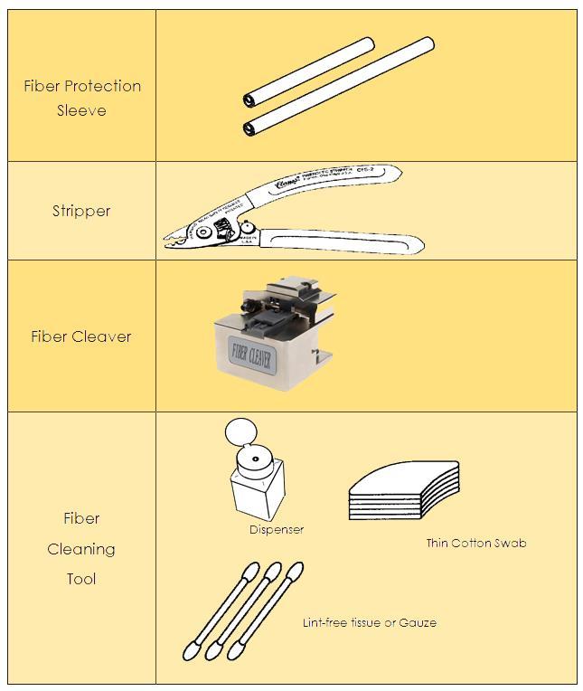


5 Components Accessory for Operation Description and Function of Splicer Panel Keyboard Right Keyboard Left Keyboard 05


6 Operation of Fiber Holders The fusion splicer equipped with an universal fiber holder, by adjusting,it can work with bare fiber,pigtail,drop cable and SOC Fiber Holder has two fiber-placing position: For drop cable and patch cord For Pigtail For Bare Fiber For 900 Bare Fiber Change the Universal and SOC fiber holders by loosen the screw Loosen the screw by this allen 06


7 Pull or push driving level to change position Pull or push driving level to change position Change the SOC Fiber Holder for SOC Splicing operation as follows Take off the fiber Put the SC to Fiber holder Prepare and Place Fiber Clean the fiber outer coating approx.100mm in length from the fiber end with alcoholimpregnated gauze or lint-free tissue. If dust or other impurities on the outer coating enter the fiber protection sleeve,burnout or breaking of fiber may result after completion of installation Protection Sleeve operation Pass the fiber through the fiber protection sleeve,(fig.3-2) 1- Cleaving Fiber 2- Remove Coating 3- Clean Bare glass 4- Cleaving Fiber 07

Put the stripped the fiber to the V-groove Fig 3-2 Protection Sleeve Operation Fig 3-3 Prepare Fiber 1.Open the cover and pressure pad, put the stripped fiber on the V-groove.")
8 Remove the fiber coating 30-40mm with a stripping tool. After this operation, handle the fiber so as not to damage its bare glass Clean the bare part with another alcohol tissue Check: After this operation, handle the fiber so as not to damage the fiber so as not to damage Check:Use high quality alcohol with greater than 99% pure Check:Change lint-free tissue each time Fiber Cleaving(1Cover,2Main body,3 Pressure pad) (1)Open the Cover and Pressure pad (2)Put the stripped the fiber to the V-groove Fig 3-2 Protection Sleeve Operation Fig 3-3 Prepare Fiber 1.Open the cover and pressure pad, put the stripped fiber on the V-groove. And make sure that the cleaver length is set as per operators intended length. 2.Close the pressure pad to fix the fiber. 3.Close the cover and make sure that the end of the fiber is sticking out of the rubber pad exactly in a straight line. 4.Push the blade carriage to the rear until it stops. 5.Open the cover 6.Take out the cleaved fiber with care in order not to bring the harm to the end face of fiber. 7.For the continuous operation,remove the cleaved fiber, in this process, be careful not to get injured by the cutting edge. Fig 3-4 Fiber Cleaving 08

9 Setting Fiber in Splicer (1)Open the wind protector. (2)Open the left and right sheath clamps. (3)Place fiber in the V-groove. Check:Make sure the fiber is not twisted when setting it into the splicer. Check:If the fiber coating has curl memory, or bend memory, Load the fiber in such a manner that the crown (curve) of the memory is turn upward. Check:Care should be taken to prevent damage or contamination of the fiber end-face. Fiber end-face contact on ANY item including V-groove bottom may result in poor quality splices. Fig 3-5 Setting Fibers I (4)Gently close the sheath clamp while holding the fiber. Check:Observe fiber setting in the V-groove. The fiber should rest in the bottom of the V- groove, Reload fiber if it does not rest properly. Check:Fiber end-face should rest between the V-groove tip and electrode center line. It is unnecessary that the fiber end-face be exactly at the midpoint. Left Sheath Clamp Right Sheath Clamp Left Fiber Fig.4-4 Setting Fibers II Right Fiber 09
Close the wind protector. Pigtail Preparing and setting 1.Prepare the pigtail 2.")


10 (5)Repeat steps(3)and(4)for second fiber. (6)Gently close the left and right fiber clamps. (7)Close the wind protector. Pigtail Preparing and setting 1.Prepare the pigtail 2.Place the pigtail to fiber cleaver and the cleaving length is 16mm Place the prepared pigtail to Fiber Holder Close the pressure pad and prepare the right side fiber,then do following step Drop cable preparing and setting 1.Prepare the drop cable as needed 2.Place the drop cable to fiber cleaver and the cleaving length is 16mm 3.Place the prepared drop cable to fiber holder 10


11 4.Close the pressure pad and prepare the right side fiber,then do following step Patch cord preparing and setting 1.Prepare the Patch Cord Small cut Cut off Big cut 11

12 2.Place the patch cord to fiber cleaver and the cleaving length is 16mm 3.Place the prepared patch cord to fiber holder 4.Place the prepared drop cable to fiber holder 12


13 Splice on connector preparing and setting 1.Prepare the Splice on connector Splice on connector Strip the SOC and keep 1mm coating 2.Place the Splicer on connector to the fiber holder and then place to fiber cleaver and cleaving 3.Place the prepared Splice on connector,together with the fiber holder, to fusion splicer 4.Close the pressure pad and prepare the right side fiber,then do following step 13
14 Splicing operation It uses image processing to identify abnormal conditions that sometimes occur during the splicing process. A small portion of these defects sometimes goes undetected and a poor quality splice occurs. Visually inspect the fiber image on the monitor to confirm acceptance or rejection during the various stage of the splicing process. (1) Start of splicing Press< >moves the left and right fibers forward. After completion of cleaning arc discharge, the fibers stop at the predetermined position. Note: When the fiber are moving forward and they appear to hop up and down, contamination may be present in the V-grooves or the fiber surface, Clean the V-grooves and redo fiber preparation. (2) Cleave angle measurement and alignment operation Visually examine the condition of the fiber end-face while the splicer is in operation or at a pause. Check:Even if no cleave angle error is displayed, press< the following cases occur. >and redo fiber preparation if Crack IPL Inclin 14

15 Fiber End Face When the threshold of cleave angle error is exceeded an error message is displayed : Left Fiber End-face badness or Right Fiber End-face badness,then redo cleave fiber. Left/Right fiber incise End-face Heating with arc discharge Fig 3-8 Alignment After aligning the fibers, the splicer will produce a high voltage arc discharge to fuse the fibers together. During arc discharge, observe the fiber image on the monitor screen. If some part of the image exhibits an extremely bright glow (hot spot),which is created by burning contaminants located on the surface or end-face of the fiber,there is a possibility that the fiber core will be deformed. Although deformation can be detected by the loss estimation function,a re-splice is recommended. 15

16 Splice Inspection Fig.3-9 Fibers Being Spliced When the spliced state is abnormal,the splicer displays an error message Splice Lost A resplice is recommended. Note:It is best to perform an arc test at this stage for the splicer to determine the best program for the fiber type. 16

17 Note: A slightly fat splice is normal. There is no problem with the splice loss and reliability. Note: White line or black line will appear on fiber s joint with fluorine and titanium, Because of optics, There s no effect to joint. Splice loss estimating The estimated splice loss is displayed on the screen Fig.3-11 Result of Fiber Splicing In some cases the splice loss can be improved with the re-arc feature. Press the< >.After re-arc discharge,not displayed of splice loss. Note:There are cases when the splice loss will deteriorate after re-arc discharge Storing splice result Press< >or open the wind protector and the splicer Will automatically perform the proof test and stores the splicing result. In the memory CMOS chip of the splice result. DVP-750 can storage 8000 item splice result 17
18 Fiber Removal (1) Open the wind protector Check:Heater clamps should be open, ready to receive fiber and splice protector sleeve. (2) Open the left sheath clamp, holding the left fiber in your hand. (3) Open the right sheath clamp, holding the right fiber in your hand. (4) Remove the fiber from the splicer. Reinforcing the Splice (1) Slide the fiber protection sleeve to the center of the splice and move it to the tube heater. Check:Make sure the splice point and fiber protection sleeve are in the center of the tube heater. Check:Make sure the reinforcing material is placed downward. Check:Make sure the fiber is not twisted. (2) While applying tension to the fiber, lower the fiber into the Center the splice point (3) Close the heater Center the splice point and the sleeve 40mm Protection Sleeve 60mm Protection Sleeve Fig.3-12 Setting in Tube Heater Check:Check again to see that the splice point and fiber protection sleeve are in the center of the tube heater. 18
19 (4) Press< >to start a tube-heating cycle. Upon completion of heating, The heater LED turns off. Note:To abort the tube heating cycle,press < > (5) Open the left and right heater clamps. While applying tension the fiber and then take off the fiber Note:On occasions the fiber protection sleeve may adhere the bottom of the tube heater. Simply use a cotton swab or similar soft tip object to gently push the fiber protection sleeve to dislodge. (6) Visually check the splice reinforcement for bubbles and impurities. Shown in Fig.4-16, Three for disqualification needed rework; Twain for eligibility. Storing the fusion splicer (1) Turn the switch to 0 position (2) Take off AC adapter (3) Fusion splicer is an exact instrument. Its carrying case is especially design, With guarantee the fusion splicer not influence of bump,dust, hydrosphere. Put in carrying case in time of the fusion Check:Cut off the power before storing. Check: Cleaning the crucial parts in time: Pickup camera,lamp-house lens, Fiber press and V- groove, Wipe off the dust and dunghill. Check: Would the LCD surveillance screen vertical vail, Entireness cling to the fusion splicer Check:Unchain the having line put in the carrying case Check: Lift the fusion splicer cased the carrying case. Check:Cased the other fittings and expendable, Lid and button the carrying case. 19

20 Note: Eliminate the liquid in the bottle in time if the alcohol bottle in the carrying case. For fear spill influence the facility. Maintenance of Splicing Quality Cleaning and Checking before Splicing Critical cleaning points and maintenance checks are described below.cleaning V-grooves If contaminants in the V-grooves, correct clamping may not occur, resulting in higher splice loss. The V-grooves should be frequently inspected and periodically cleaned during normal operation. (1) Open the wind protector and fiber clamps. (2) Clean the bottom of the V-groove with an alcohol-impregnated thin cotton swab as shown in Fig. 4-l. Remove excess alcohol from the V-groove with a clean dry swab. Check:Use a high quality alcohol, greater than 99% pure. Check:Do not use excessive force when cleaning the V-groove The V-groove may be damaged Fig.4-1 Cleaning V-grooves (3) If the contaminants in V-groove cannot be removed with an alcohol-impregnated thin cotton swab, use a cleaved fiber end-face to dislodge contaminants from V-groove bottom. Repeat step (2) after this procedure. 20

21 Fig.4-2 Cleaning V-grooves with Cleaved Fiber Cleaved Fiber V-Groove Cleaning Fiber Clamp Chips If contaminants are present on the clamp chips,correct clamping may not occur,resulting in poor quality fiber alignment splices.the fiber clamp chips should be frequently inspected and periodically cleaned. (1)Open up the wind protector (2)Clean press stand surface with an alcohol-impregnated thin cotton swab.remove excess alcohol from the press stand surface with a clean dry swab Check: Use a high quality alcohol greater than 99% pure cotton swab fiber press stand cleaning fiber press stand. 21
22 Cleaning Mirrors surface Fig 4-3 Clean Pressure Foot Pressure Foot If the mirrors surface becomes dirty, the core position may be incorrect due to decreased optical path clarity, resulting in higher splice loss. (1) Clean the mirror surface with an alcohol-impregnated thin cotton swab as shown in Fig.4-4. Remove excess alcohol from the mirror surface with a clean dry swab. Check:Use a high quality alcohol, greater than 99% pure. (2)Mirror should be clean and smudge free. Fig 4-4 Clean Protector Mirror Mirror 22
23 Program Test Atmospheric conditions such as temperature,humidity,and pressure are constantly changing which create variability in the arc temperature. The splicer contains a temperature, humidity,and pressure sensors that are used in a constant feedback monitoring control system to regulate the arc power at a constant level. Changes in arc power due to electrode wear and glass adhesion cannot be corrected automatically. Also, the center position of arc discharge sometimes shifts to the left or right. Using fusion splicer at herein after conditions, Also discharge test: Highest temperature, Lowest temperature, Too desiccation, Too humidity, Electro deinferior, Different fiber connect, After cleanness and instead electrode, Or all condition are concurrence. Arc test according to specifically fusion program request discharge intensity, Selfregulation discharge parameter, And seed discharge high temperature area adjust fiber center station. (1) Program test need twain fiber. According to commonly fusion means vs fiber stripper sever and placed (2) In wait for state,press< >enter Setup Menu Fluctuate arrowhead move to Program Test,Press< >start program test. (3) Program test automatism adjust discharge intensity. Repeat test until screen display Arc good (4) After program test, Press< >exit and return to automatism splicing state 23

24 Menu Commands Menu Commands Tree Program Test Welding machine with a built in discharge test system. Users should be regular operation, to ensur stable quality. See page for specific operation. Selects Program In standby state,press< >enter Program,move or to select program,press< > to confirm it Move cursor to fiber type,press< > to confirm,press < > to exit Fig 5-1 Select Program 24

25 Fiber kind of fibers: Fiber Type SM MM DS NZDS G657 Meaning Single mode Multi mode Dispersion shifted Non-zero Dispersion shifted G657 Fig.5-2 Program Modify Function Function Explain Value area PreArc Time Prefuse Time 0~1 PreArc Power Prefuse Power 0~250 Arc Time Fusion arc time 0~10.0 Arc Power Fusion arc power 0~250 Forward Fiber move forward in fusion time 0~60 Fiber move forward in fusion time Fiber move speed in fusion time 1~10 leave Angle Fiber incise end-face angle 0~5.0 Re Re-Arc time Re-arc interval 0~25.0 Working type In standby state,press < > enter program menu,press enter fusion set; press or change work type(see Fig 5-3 work type) Press< > confirm,press< >exit. 25


26 AUTO working type Fig5-3 Work Type Auto working type is the commonly used type,after clean and cleave fiber,the fusion splicer will automatically do splicing operation. Manual working type With this working type,alignment,arc...will operated by manual. Heat time In Standby State,Press< > enter Program Menu,press move the cursor to Fusion Set,use or move the cursor to heating time,press< >enter; use or add or cut time(see Fig 5-),After then press< >exit Fig5-4 Heating time 26


27 Fusion Record Enter this menu,may check the last 8000 record Press< > enter Program Menu,press< > enter Fusion Record and choose View Records,Press < >enter(fig 5-6) Error Message List Fig 5-6 Fusion Record Follow the remedy precisely as shown in the following lists. If it is not possible to eliminate the problem, there is the possibility of the splicer being faulty and the splicer may require service. Consult your nearest us with the following information:.model name of the splicer Serial number of the splicer Error message Situation when the error occurs Error Message Reason Remedy Replace Left fiber Replace Right fiber Replace both fiber Left cleave bad Right cleave bad Both cleave bad Please close the wind protector Fusion failure The left fiber is set too far back. The right fiber is set too far back. The left or right fiber is set too back..bad fiber end-face.dust or dirt on the fiber surface..end-face angle set up too strict.dust or dirt on the objective lens or the wind protector mirror. Unable to start splicing when the wind protector opens. The wind protector is opened during splicing operation. The fiber stuff amount is insufficient. The pre-fuse power is too strong. Reset, Moves left fiber forward Reset, Moves right fiber forward Reset, Moves left/right fiber all forward Reset, Moves left or right fiber forward.check the condition of fiber cleaver. When the blade is worn, rotate the blade..put End-face angle loose to suitable degree Anew preparation fiber lean the lens or mirrors Press< >reset after closing the wind protector Increase stuff amount in the parameter setup menu Minish pre-fuse power in the parameter setup menu 27
OFS-80. Optical Fiber Fusion Splicer. User s Manual
 OFS-80 Optical Fiber Fusion Splicer User s Manual Shineway Technologies, Inc. OFS-80 Optical Fiber Fusion Splicer Notices Copyright, ShinewayTech, All rights reserved. No part of this manual may be reproduced
INSTRUCTION MANUAL 910FS
 INSTRUCTION MANUAL 910FS Optical Fiber Fusion Splicer Read and understand all of the instructions and safety information in this manual before operating or servicing this tool. Register this product at
OFS-935C. Fusion Splicer. Operation Guide
 Fusion Splicer Operation Guide Table of Contents Introduction...3 Specifications...3 How to replace the fiber...5 Cleaning...5 Splice...6 Splice Menu...7 Maintenance...12 Diagnostic...13 Electrode...15
Instruction Manual SAT-17T OPTICAL FUSION SPLICER
 Instruction Manual SAT-17T OPTICAL FUSION SPLICER Before operating the equipment, please carefully read this instruction manual Do follow all safety instructions and warnings covered in this manual. Take
All In One Fusion Splicer
 Economical Solution for Integrated Fiber Preparation Tool Demand. All In One Fusion Splicer US Patent /92,09 The Revolution of a Splicer Features The Single All In One Device (strip, clean, cleave, splice,
ORIENTEK T40 Optical Fiber Fusion Splicer. User s Manual
 ORIENTEK T40 Optical Fiber Fusion Splicer User s Manual Safety Summary The following general safety precautions must be observed during all phases of operation of this instrument. Failure to comply with
Table of Contents. Type 65 Micro-Mass Fusion Splicer
 Table of Contents Type 65 Micro-Mass Fusion Splicer 1.0 GENERAL... 1 1.1 SPECIFICATIONS... 2 1.2 STRUCTURE... 4 1.3 OPERATING RECOMMENDATIONS... 6 2.0 SAFETY PRECAUTIONS... 8 3.0 REFERENCE DOCUMENTS (U.S.
Optical Fusion Splicer
 Optical Fusion Splicer Fiberer Global Tech Ltd NO. 1 Service NO.1 Quality F-KL-260C Both X and Y axis display Large multiple & visible fiber core Turn-over display screen to use conveniently Inner light
Instruction Manual LAMI CORPORATION INC.
 Instruction Manual LAMI CORPORATION INC. Preface Thank you for purchasing our. This Instruction Manual (document) includes details for safe use of this product. Please read this document thoroughly before
The Sumitomo Type-37 Micro-Core Fusion Splicer GUIDE TO OPERATION
 The Sumitomo Type-37 Micro-Core Fusion Splicer GUIDE TO OPERATION TYPE-37 Micro-Core FUSION SPLICER OPERATION MANUAL Sumitomo Electric Lightwave Corp. All rights reserved. 78 Alexander Drive Trademarks
FITEL S153A Ver.2 Hand-held Active Alignment Splicer
 FITEL S53A Ver.2 Hand-held Active Alignment Splicer S53A ver.2 NEW features The S53A Active 3 Axis Cladding Alignment Fusion Splicer has been enhanced and updated to version 2. The battery is automatically
OPTICAL FIBER FUSION SPLICER
 AI-8 AI-7 NEW PRODUCT LAUNCH CLASSIC MASTERPIECE Signal Fire AI-8 use the latest core alignment technology with auto focus and six motors, it is a new generation of fiber fusion splicer. It is fully qualified
Optical Fusion Splicer AbsySplicer-AV6472 ABSYS S.A.
 Optical Fusion Splicer AbsySplicer-AV6472 Tel : 01 69 63 26 36 Fax : 01 69 63 26 37 91460 Marcoussis ventes@absysfrance.com Overview: AbsySplicer-AV6472 is a high performance optical fiber splicing device
FITEL S178 Ver.2 Hand-held Core-Alignment Fusion Splicer
 FITEL S78 Ver.2 Hand-held Core-Alignment Fusion Splicer S78A ver.2 NEW features The S78A Hand-Held Core-Alignment Fusion Splicer has been enhanced and updated to version 2. The battery is automatically
TOSHIBA Thermal Printer B-852-R SERIES. Maintenance Manual. Document No. EO Original Mar., 2006 (Revised ) PRINTED IN JAPAN
 PRINTED IN JAPAN") TOSHIBA Thermal Printer B-852-R SERIES Maintenance Manual Original Mar., 2006 (Revised ) Document No. EO18-33018 PRINTED IN JAPAN EO18-33018 TABLE OF CONTENTS Page 1. UNPACKING --------------------------------------------------------------------------------------------1-1
TOSHIBA Thermal Printer B-852-R SERIES Maintenance Manual Original Mar., 2006 (Revised ) Document No. EO18-33018 PRINTED IN JAPAN EO18-33018 TABLE OF CONTENTS Page 1. UNPACKING --------------------------------------------------------------------------------------------1-1
Motion System Components Diagram. Note: #2 Mirror Cover and X-Axis Motor Cover have been removed for visibility. Maintenance.
 Professional Laser System PLS3.75, PLS4.75, PLS6.75 and PLS6.150D Keeping the laser system clean will ensure the highest quality engraving. A clean laser system is the best performing laser system. The
This chapter describes how to perform periodic inspection and maintenance to ensure the long operating life of the chamber.
 Basic guide Chapter 5 Inspection and maintenance Air to Air Thermal Shock Chamber Chapter 5 Inspection and maintenance This chapter describes how to perform periodic inspection and maintenance to ensure
Lumitester PD-20 Control Kit
 日本語による取扱説明は 17 ページからとなります Lumitester PD-20 Control Kit Operation manual Thank you for purchasing the Lumitester PD-20 Control Kit. To use this kit safely and correctly, read this operation manual carefully
No. Tool Vendor P/N. Furukawa FITEL Furukawa FITEL Furukawa FITEL Furukawa FITEL Furukawa FITEL Furukawa FITEL Furukawa FITEL.
 TOUCH Plus SC Splice-On Connector for Cordage Standard assembly procedure of TOUCH Plus SC Splice-On Connector is as below. Caution : Wear eye protection glasses when handling optical fibers. 1. Preparation
Section 10: Engraving Machine Cleaning
 Section 10: Engraving Machine Cleaning In This Section Cleaning Important! Laser Tube Cleaning - Important! Fire Warning! Through normal use your laser system can collect debris and soot that are potentially
Troubleshooting Guide: 355 Lights (12V)
") Troubleshooting Guide: 355 Lights (12V) Contents Description Refer To: Troubleshooting - Troubleshooting Chart Adjustments / Repair Procedures Bulb Replacing the Bulb Fuse(s) Replacing the Fuse (Ceiling)
Troubleshooting Guide: 355 Lights (12V) Contents Description Refer To: Troubleshooting - Troubleshooting Chart Adjustments / Repair Procedures Bulb Replacing the Bulb Fuse(s) Replacing the Fuse (Ceiling)
Operations and Service Manual. X30208 Load Bank
 Operations and Service Manual Read all instructions before using the load bank Contents 1. Components... 3 Total Assembly... 3 2) Specifications... 4 a)... 4 3) Receiving... 5 4) Safety... 5 a) Ground
Requests for Daily Care and Maintenance
 Inkjet printer JFX200-2513 Requests for Daily Care and Maintenance This machine is a precision machine equipped with extremely fine mechanisms. Especially, the nozzle surface of the heads from which the
OPERATION INSTRUCTIONS
 www.r-techwelding.co.uk Email: sales@r-techwelding.co.uk Tel: 01452 733933 Fax: 01452 733939 ProArc 175 INVERTER ARC WELDER OPERATION INSTRUCTIONS Version 2017-10 2 3 Thank you for selecting the R-Tech
Maintenance Adjustments
 4 Maintenance and Adjustments Chapter Contents Cleaning the Printer and Paper Handling Accessories..... 158 Cleaning the HP Digital Copier....................... 161 Cleaning ADF and Glass............................
TOSHIBA Thermal Printer B-SX6T/SX8T SERIES. Maintenance Manual. Document No. EO Original Mar., 2006 (Revised ) PRINTED IN JAPAN
 PRINTED IN JAPAN") TOSHIBA Thermal Printer B-SX6T/SX8T SERIES Maintenance Manual Original Mar., 2006 (Revised ) Document No. PRINTED IN JAPAN TABLE OF CONTENTS Page 1. UNPACKING--------------------------------------------------------------------------------------------------------
TOSHIBA Thermal Printer B-SX6T/SX8T SERIES Maintenance Manual Original Mar., 2006 (Revised ) Document No. PRINTED IN JAPAN TABLE OF CONTENTS Page 1. UNPACKING--------------------------------------------------------------------------------------------------------
Requests for Daily Care and Maintenance
 Inkjet printer UJF-3042MkII/3042MkII EX/6042MkII Requests for Daily Care and Maintenance This machine is a precision machine equipped with extremely fine mechanisms. Especially, the nozzle surface of the
1200W CaR PoliSheR en RS4900
 1200W Car Polisher RS4900 RS4900 8 1 2 7 3 4 5 6 A B flat nozzle C D E F 1200W Car Polisher RS4900 G H flat nozzle I J K L 4 1200W Car Polisher COMPONT LIST 1 2 3 4 5 6 7 Variable speed control Switch
MAINTENANCE MANUAL ARC FUSION SPLICER FSM 40S LEVEL 2
 KSP75-0086-51-02 (3) MAINTENANCE MANUAL ARC FUSION SPLICER FSM 40S LEVEL 2 Fujikura Proprietary Document No part of this document may be transferred to any third party without prior written consent from
B-RAD Select USER MANUAL TABLE OF CONTENTS
 TABLE OF CONTENTS TABLE OF CONTENTS... 1 MANUAL REVISION HISTORY... 2 IMPORTANT SAFETY NOTICE... 3 1.0 General Information... 5 1.1 System Components... 5 1.2 Specifications... 5 1.2.1 Torque Ranges...
XS400 Load Bank. Read all instructions before using the load bank. Contents
 Read all instructions before using the load bank Contents 1) Components... 3 Total Assembly... 3 2) Specifications... 4 3) Receiving... 4 4) Safety... 5 a) Grounding cam... 6 b) Power connections... 6
3M No Polish Connector 8800-APC/AS SM SC/APC, Angle Splice, 250/900 µm Instructions
 3M No Polish Connector 8800-APC/AS SM SC/APC, Angle Splice, 250/900 µm Instructions February 2008 78-8140-1581-0 Contents 1.0 Summary...3 2.0 Connector Preparation...4 3.0 Fiber Preparation...4 4.0 Fiber
Troubleshooting Guide: 355 Lights (24V)
") Troubleshooting Guide: 355 Lights (24V) Contents Description Refer To: Troubleshooting - Troubleshooting Chart Adjustments / Repair Procedures Bulb Replacing the Bulb Fuse(s) Replacing the Fuse (Ceiling)
Troubleshooting Guide: 355 Lights (24V) Contents Description Refer To: Troubleshooting - Troubleshooting Chart Adjustments / Repair Procedures Bulb Replacing the Bulb Fuse(s) Replacing the Fuse (Ceiling)
TR22F Repair Manual (Electronics)
") TR22F Repair Manual (Electronics) Table of Contents 1-1-1. Product Picture - TR22F 1-2-1. Overlay - TR22F 1-3-1. Component Placement - TR22F Display Board 1-3-2. Component Placement - TR22F Lower Compartment
TR22F Repair Manual (Electronics) Table of Contents 1-1-1. Product Picture - TR22F 1-2-1. Overlay - TR22F 1-3-1. Component Placement - TR22F Display Board 1-3-2. Component Placement - TR22F Lower Compartment
RF6 / RF10 / RF18 Installation Instructions
 RF6 / RF10 / RF18 Installation Instructions Thank you very much for purchasing PIAA product. Read this instruction manual thoroughly for proper use of the product. After completing your installation, please
ION JET NOZZLE NIH-55
 ION JET NOZZLE NIH-55 INSTRUCTION MANUAL - Read this instruction manual and make sure you thoroughly understand its contents before attempting to operate, inspect or service this product. - The users and
Cybex Arc Trainer Owner s & Service Manual. 7 - Service
 7 - Service Table of Contents......... iii Warnings/Cautions All warnings and cautions listed in this chapter are as follows:! WARNING: All maintenance activities shall be performed by qualified personnel.
OPERATOR S MANUAL StudPro LiteXI Pin Welder Stud Welding Products, Inc
 OPERATOR S MANUAL StudPro LiteXI Pin Welder CONTENTS Description Pages Safety 2 Specifications and Features 3 Product Components 4-5 Screen Operation 6-8 Setup and Welding 9-11 CD Gun Exploded View 12
Request for daily care
 Daily Care Manual Request for daily care Inkjet printer is the precision machine that has highly delicate mechanism. Especially, little dust and paper powder may have effect on a head nozzle firing ink,
XCM12 Mini-Centrifuge
 Multi-speed Digital User Manual v. 1.0 C&A Scientific Disclaimer C & A Scientific owns the copyright of this user manual. No person shall reprint or distribute the contents of this user manual, including
OWNER'S MANUAL WARNING DANGER. Propane cylinders sold separately. The propane cylinder must be disconnected when this firebowl is not use.
 OWNER'S MANUAL READ BEFORE USE! Model No.: BH5003-3 Style No.: 66646 For Outdoor Use Only! Use Propane Gas Only! Propane cylinders sold separately. USE PROPANE GAS ONLY! -Do not store or use gasoline or
1-50 KVA SINGLE-PHASE SERVO REGULATOR INSTRUCTIONS FOR USE SERVO SINGLE-PHASE VOLTAGE REGULATOR
 1-50 KVA SINGLE-PHASE SERVO REGULATOR INSTRUCTIONS FOR USE SERVO SINGLE-PHASE VOLTAGE REGULATOR I Important Notice! Thank you for preferring us. Your product has been designed to protect your sensitive
Dust cover. Plug. Outlet. Wire pole holder
 Thank you for choosingxtreme machine,baby -Mammoth (4 head), designing with double gear-driving, planetary grinding with four plates. The machine speed can reach 1800 rpm. Aluminum alloy gear box with
3M No Polish LC/APC Connector SM, Angle Splice, 250/900 µm 8830-APC/AS
 3M No Polish LC/APC Connector SM, Angle Splice, 250/900 µm 8830-APC/AS Instructions January 2009 78-8140-3691-5-A Contents 1.0 Summary...3 2.0 Connector Preparation...4 3.0 Fiber Preparation...4 4.0 Fiber
BlueFin User's Manual. Version 1.1
 BlueFin User's Manual Version 1.1 10 August 2005 1 Safety Precautions Battery charging The BlueFin unit comes with a power adapter. Please use this power adapter for operating the unit and charging the
Model: SPTOGT01 TRACTOR PTO GENERATOR
 www.scintex.com.au sales@scintex.com.au Model: SPTOGT01 TRACTOR PTO GENERATOR SET UP, OPERATING, AND SERVICING INSTRUCTIONS Read this material before using this product. Failure to do so can result in
MODULATING SERVICE ELECTRIC ACTUATORS OPERATION AND MAINTENANCE MANUAL COMMERCIAL AND INDUSTRIAL VALVES AND AUTOMATION
 SERIES 000/S-X MODULATING SERVICE ELECTRIC ACTUATORS OPERATION AND MAINTENANCE MANUAL COMMERCIAL AND INDUSTRIAL VALVES AND AUTOMATION Publication S000X- VER045- For information on this product and other
SZ2-ILA INSTRUCTIONS TRANSMITTED ILLUMINATION ATTACHMENT SZ-ADD SZ-POL-2 SZH-CLJ. Optional Modules
 Optional Modules SZ-ADD SZ-POL-2 SZH-CLJ INSTRUCTIONS TRANSMITTED ILLUMINATION ATTACHMENT This instruction manual is for the Olympus Transmitted Illumination Attachment. To ensure the safety, obtain optimum
KING CANADA 950W PORTABLE GENERATOR MODEL: KCG-951G INSTRUCTION MANUAL COPYRIGHT 2011 ALL RIGHTS RESERVED BY KING CANADA TOOLS INC.
 KING CANADA 950W PORTABLE GENERATOR MODEL: KCG-951G INSTRUCTION MANUAL COPYRIGHT 2011 ALL RIGHTS RESERVED BY KING CANADA TOOLS INC. WARRANTY & SERVICE INFORMATION 1-YEAR LIMITED WARRANTY FOR THIS 950W
WARNING. This product uses High Brightness LEDs. Direct viewing of the SMD LEDs at close range should be avoided. Keep product away from children.
 WARNING Before use please remove the LED Tape from its bag and allow the odour to dissipate in an unused room or outdoor building. Wash Hands after handling. This product uses High Brightness LEDs. Direct
MODEL NUMBER: MEDIUM DUTY ONBOARD AIR SYSTEM
 MODEL NUMBER: 10003 MEDIUM DUTY ONBOARD AIR SYSTEM IMPORTANT: It is essential that you and any other operator of this product read and understand the contents of this manual before installing and using
OPERATOR S MANUAL ACE - P100
 OPERATOR S MANUAL ACE - P100 Pin Welder TRU-WELD EQUIPMENT COMPANY www.truweldstudwelding.com (330) 725-7744 CONTENTS Description Pages Warranty Information 1 Safety 2 Specifications and Features 3 Product
S123 v2 Fusion Splicers Hand-Held Clad Alignment Fusion Splicer
 FUSION SPLICERS S23 v2 Fusion Splicers Hand-Held Clad Alignment Fusion Splicer Features and Benefits RoHS IP52 5 Axis Shock Illumination lamp lights up a wide area around V-grooves Rugged and compact hand
ELECTRONIC CONTROL ACTUATOR
 ELECTRONIC CONTROL ACTUATOR Nucom Series LINEAR TYPE Nucom L25 Nucom L50 OPERATION MANUAL Koei Industry Co., Ltd. FOR YOUR SAFETY In order for better and safety use of the product for a long period, please
Cat. No. I526-E1-1 USER S MANUAL 3G3IV-PLKEB2 /4. Braking Resistor Units 3G3IV-PCDBR2 B/4 B. Braking Units
 Cat. No. I526-E1-1 USER S MANUAL 3G3IV-PLKEB2 /4 Braking Resistor Units 3G3IV-PCDBR2 B/4 B Braking Units Thank you for choosing an OMRON Braking Resistor Unit and Braking Unit. Proper use and handling
OPERATING INSTRUCTIONS
 OPERATING INSTRUCTIONS BATTERY CHARGER IR-200BC TABLE OF CONTENTS 1. SAFETY PRECAUTIONS... 2 2. GENERAL DESCRIPTION... 3 3. HANDLING PRECAUTIONS... 3 4. NOMENCLATURE AND FUNCTIONS... 4 5. CHARGING... 5
MMA 160S ARC/MMA WELDER OPERATION INSTRUCTIONS
 www.r-techwelding.co.uk MMA 160S ARC/MMA WELDER OPERATION INSTRUCTIONS 2 Thank you for selecting the R-Tech MMA160S Inverter Arc Welder. The MMA160S has many benefits over traditional Arc welders, including
X100P Load Bank. Read all instructions before using the load bank. Contents
 X100P Load Bank Read all instructions before using the load bank Contents 1. Components... 3 Total Assembly... 3 2) Specifications... 4 a) X100P Load Bank... 4 3) Receiving... 4 4) Safety... 5 a) Grounding...
The RCS-6V kit. Page of Contents. 1. This Book 1.1. Warning & safety What can I do with the RCS-kit? Tips 3
 The RCS-6V kit Page of Contents Page 1. This Book 1.1. Warning & safety 3 1.2. What can I do with the RCS-kit? 3 1.3. Tips 3 2. The principle of the system 2.1. How the load measurement system works 5
BRAVER UPS. (Uninterruptible Power System) User s Manual
 User s Manual") BRAVER UPS (Uninterruptible Power System) User s Manual Safety CAUTION! This UPS utilizes voltages that may be hazardous. Do not attempt to disassemble the unit. The unit contains no user replaceable parts.
BRAVER UPS (Uninterruptible Power System) User s Manual Safety CAUTION! This UPS utilizes voltages that may be hazardous. Do not attempt to disassemble the unit. The unit contains no user replaceable parts.
OPERATOR S MANUAL STUDPRO SERIES
 OPERATOR S MANUAL STUDPRO SERIES Capacitor Discharge Stud Welder MODELS: StudPro 2500XI StudPro 2500XIP StudPro 3125XI StudPro 3750XI CONTENTS Description Pages Safety 2 Specifications and Features 3 Product
KEWTECH. KT56 digital multi function tester. Instruction manual
 KEWTECH KT56 digital multi function tester Instruction manual Contents 1 Safety Notice 1 2 Features and Principles of Measurement 3 3 Introduction 6 4 Specifications 7 5 Instrument layout 9 6 Operating
MODEL MA4210 Installation and Operation Manual Important:
 MODEL MA4210 Installation and Operation Manual Important: This manual contains specific cautionary statements relative to worker safety. Read this manual thoroughly and follow as directed. It is impossible
60V RECHARGEABLE LITHIUM-ION BATTERY
 60V RECHARGEABLE LITHIUM-ION BATTERY LB60A00/LB60A03/LB60A01/LB60A02 Owner s Manual TOLL-FREE HELPLINE: 1-855-345-3934 www.greenworkstools.com Read all safety rules and instructions carefully before operating
Instruction Manual for FI Controller
 Instruction Manual for FI Controller Thank you for purchasing one of our TAKEGAWA s products. Please strictly follow the instructions to install and use the products. Before installing the products, please
OPERATOR S MANUAL. TW-i SERIES. Capacitor Discharge Stud Welder. MODELS: TW-i 250 TW-i 250CP TW-i 321 TW-i 375
 OPERATOR S MANUAL TW-i SERIES Capacitor Discharge Stud Welder MODELS: TW-i 250 TW-i 250CP TW-i 321 TW-i 375 TRU-WELD EQUIPMENT COMPANY www.truweldstudwelding.com (330) 725-7744 CONTENTS Description Pages
Maintenance Manual WATER SUMP CONTROL VALVE F532B
 WATER SUMP CONTROL VALVE F532B LIST OF EFFECTIVE PAGES On a revised page, the portion of text or illustrations affected by the change is indicated by a vertical line in the outer margin of the page. When
OPERATIONS MANUAL. Mini Centrifuge Model MCF Certified
 OPERATIONS MANUAL Mini Centrifuge Model MCF-2360 Certified Contents 1. Safety 2 2. Introduction 7 3. Package Contents 7 4. Specifications 8 5. Features 8 6. Parts of the Mini Centrifuge 9 7. Installation
Control. Part B, Section 2. This section covers the following unit configurations. 3400V 3500V. Voltage 4. Pump Piston (E, F, G)
") Part B, Section 2 Model This section covers the following unit configurations. Voltage 4 3100V 3400V 3500V Pump Piston (E, F, G) Manifold 4-Port (A) 6-Port (B, C) 2-Port (S, T) Vista Standard (V) B 2-0
Part B, Section 2 Model This section covers the following unit configurations. Voltage 4 3100V 3400V 3500V Pump Piston (E, F, G) Manifold 4-Port (A) 6-Port (B, C) 2-Port (S, T) Vista Standard (V) B 2-0
This symbol indicates information that, if ignored, could possibly result in personal injury or even death due to incorrect handling.
 Installation Guide Safety Instructions For your safety, read all the instructions in this guide before using the mounting bracket. Incorrect handling that ignores instructions in this guide could damage
T611 Repair Manual (Electronics)
") T611 Repair Manual (Electronics) Table of Contents 1-1-1. Product Picture T611 1-2-1. Overlay T611 1-3-1. Component Placement T611 Display Board 1-3-2. Component Placement T611 Lower Compartment 1-4-1.
T611 Repair Manual (Electronics) Table of Contents 1-1-1. Product Picture T611 1-2-1. Overlay T611 1-3-1. Component Placement T611 Display Board 1-3-2. Component Placement T611 Lower Compartment 1-4-1.
ELECTRONIC CONTROL ACTUATOR
 ELECTRONIC CONTROL ACTUATOR Nucom Series LINEAR TYPE Nucom L100 OPERATION MANUAL Koei Industry Co., Ltd. FOR YOUR SAFETY In order for better and safety use of the product for a long period, please observe
SYSTEM 4000 TRIMMER DBM-400T
 SYSTEM 4000 TRIMMER Instruction Manual DUPLO CORPORATION INTRODUCTION Thank you for your purchase. To ensure correct usage, please read this instruction manual thoroughly, especially the section Safety
CORNING. CamSplice User Guide 2. TOOLS AN MATERIALS 1. GENERAL 3. LOADING CAMSPUCE INTO TOOL
 CORNING CamSplice User Guide pin 006-038, Issue 13 1. GENERAL This procedure outlines the use of the Cam Splice and TKT-1 00-01 and TKT-100-02 tool kit for splicing optical fibers (see Table 1). This document
CH4100 Series High Efficiency Intelligent Charger. ThunderStruck User Manual Ver. 1.02
 CH4100 Series High Efficiency Intelligent Charger ThunderStruck User Manual Ver. 1.02 Table Of Contents I. Product Overview II. Safety III. Preventing Leakage and Fire 1.Correct use of Breakers, Sockets
EVS RP6020. Instruction Manual
 Instruction Manual TDK Lambda BEFORE USING THE PRODUCT Be sure to read this instruction manual thoroughly before using this product. Pay attention to all cautions and warnings before using this product.
Click Here for Printable PDF File. CHAPTER 3 - BASIC INFORMATION for PERFORMING HYDRAULIC SYSTEM MAINTENANCE
 HWH Online Technical School Lesson 1: Introduction to Hydraulics Chapter 3 - "BASIC INFORMATION for PERFORMING HYDRAULIC SYSTEM MAINTENANCE" (Filename: ML57000-012-CH3.DOC Revised: 22APR16) Click Here
TSM2500 Series High Efficiency Intelligent Charger. ThunderStruck User Manual Ver. 1.05
 TSM2500 Series High Efficiency Intelligent Charger ThunderStruck User Manual Ver. 1.05 Table Of Contents I. Product Overview II. Safety III. Preventing Leakage and Fire 1.Correct use of Breakers, Sockets
High Vacuum Diaphragm-Type Dry Vacuum Pump
 No 腄 26300-2-02-3 High Vacuum Diaphragm-Type Dry Vacuum Pump DTC-120 DTC-120A, 120B, 120C (According to CE) Request to Users Please read this manual thoroughly to ensure safe and effective use of the equipment.
INSTRUCTION MANUAL ANGLE GRINDER PT W
 INSTRUCTION MANUAL ANGLE GRINDER PT50360 4½ INCHES 120V 60Hz 600W 5A 12,000 rpm C US Note : Before operating this tool, read this manual and follow all safety rules and operating instructions. This electric
3M No Polish Connector 8800-APC/AS SM SC/APC, Angle Splice, 250/900-µm. Instructions. October C
 3M No Polish Connector 8800-APC/AS SM SC/APC, Angle Splice, 250/900-µm Instructions October 2010 78-8140-1581-0-C Contents 1.0 Summary...3 2.0 Connector Preparation...4 3.0 Fiber Preparation...4 4.0 Fiber
RAUTOOL G2 BATTERY HYDRAULIC TOOL KIT PRODUCT INSTRUCTIONS. Construction Automotive Industry
 RAUTOOL G2 BATTERY HYDRAULIC TOOL KIT PRODUCT INSTRUCTIONS www.rehau.com Construction Automotive Industry TABLE OF CONTENTS Safety Information... 3 Items Supplied............................................4
Copyright 2004 Alcatel. All rights reserved.
 Alcatel assumes no responsibility for the accuracy of the information presented, which is subject to change without notice. Alcatel, the Alcatel logo, MainStreet, and Newbridge are registered trademarks
Package Contents Part A (3) I-Beam (1) Base (2) Other parts
 I-Beam (1) Base (2) Other parts") Page 1 Installation Instructions for 81245 Adjustable Height Gantry Crane 1-Ton Capacity Table of Contents Important Safety Information pg. 2 Specific Operation Warnings pg. 2 Main Parts of Product pg.
Page 1 Installation Instructions for 81245 Adjustable Height Gantry Crane 1-Ton Capacity Table of Contents Important Safety Information pg. 2 Specific Operation Warnings pg. 2 Main Parts of Product pg.
Tooling Assistance Center
 Safeguards are designed into this application equipment to protect operators and maintenance personnel from most hazards during equipment operation. However, certain safety precautions must be taken by
Roller Door Operator
 INSTALLATION INSTRUCTIONS AND OWNERS MANUAL Roller Door Operator IMPORTANT PLEASE READ THESE INSTRUCTIONS CAREFULLY PRIOR TO COMMENCING THE INSTALLATION OF THE OPERATOR UNIT CAUTION This Automatic Opener
OPERATING INSTRUCTIONS
 CM OPERATING INSTRUCTIONS 9 Function, Auto Range Digital Multi-Meter DM6450 INTERTEK Read this owner s manual thoroughly before use and save. C LISTED US I. DISPLAY FUNCTIONS & SYMBOLS 9 6 10 11 14 8 7
GARAGE DOOR OPENER OWNER S MANUAL S3/S4
 GARAGE DOOR OPENER OWNER S MANUAL S3/S4 Features! Locking door during power failure: If power failure occurs while the door is operating, the door can be released by pulling the clutch down, allowing
Technical Service Bulletin IOX/DCX Transmitter Maintenance Schedule
 Technical Service Bulletin 140610 IOX/DCX Transmitter Maintenance Schedule Service Bulletin 140610 applies to Comark IOX, DCX and Paragon transmitters. This bulletin contains important maintenance schedule
Lumitester PD-30. Instruction Manual. Table of Contents
 Table of Contents Lumitester PD-30 Instruction Manual Thank you very much for purchasing the Lumitester PD-30. All of this Instruction Manual must be read before operation of this product for safe and
OPEN/CLOSE SERVICE ELECTRIC ACTUATORS OPERATION AND MAINTENANCE MANUAL COMMERCIAL AND INDUSTRIAL VALVES AND AUTOMATION
 SERIES 1000-X OPEN/CLOSE SERVICE ELECTRIC ACTUATORS OPERATION AND MAINTENANCE MANUAL COMMERCIAL AND INDUSTRIAL VALVES AND AUTOMATION Publication S1000X-110 VER0215-1 For information on this product and
OPERATIONS MANUAL LEVER CHAIN HOIST
 OPERATIONS MANUAL LEVER CHAIN HOIST IMPORTANT SAFETY INFORMATION Please read, understand and follow all safety information contained in these instructions prior to the use of this hoist. Retain these instructions
K&L MC200 ELITE WHEEL BALANCER Product Manual - MC Wheel Balancing
 Product Manual - MC Wheel Balancing Thank you for purchasing this K&L Product. Please inspect this unit for damage prior to use. This manual will review balancing a motorcycle wheel. Please read the entire
Instruction Manual. Table of Contents. Powder Clutch, Brake MODEL ZKB-AN,BN Powder Clutch ZKB-YN,XN Powder Brake
 ZJ-267A Powder Clutch, Brake MODEL ZKB-AN,BN Powder Clutch ZKB-YN,XN Powder Brake Instruction Manual Table of Contents Cautions on Safety - - - - - - - - - - - - - - - - - 1 1. Cautions before use - -
Operations and Service Manual. XE400D-SB Load Bank
 Operations and Service Manual XE400D-SB Load Bank Read all instructions before using the load bank Contents 1. Components... 3 Total Assembly... 3 2) Specifications... 4 a) XE400D-SB Load Bank... 4 3)
TOPAZ Service Guide. Full Service
 TOPAZ Service Guide Full Service SERVICE OVERVIEW This manual will guide you step by step performing an air service to your Topaz. Please follow each instruction carefully to achieve the best and safest
Part No Series 12 to 144 Volt TSM Series. High Efficiency Intelligent Charger. Offered by Lithionics Battery for Use in Conjunction
 Part No. 20-300 Series 12 to 144 Volt TSM Series High Efficiency Intelligent Charger Offered by Lithionics Battery for Use in Conjunction with the NeverDie Battery Management System (BMS) CANbus SoC Meter
DIGITAL TORQUE GAUGE MODEL BTGE-G
 DIGITAL TORQUE GAUGE MODEL BTGE-G OPERATING INSTRUCTION BTGE-G BTGE-G Model To use this product properly and safely, please read this manual carefully before use. If you have any question about the product
1/2 HP SUMP PUMP OWNER'S MANUAL
 TM 1/2 HP SUMP PUMP OWNER'S MANUAL WARNING: Read carefully and understand all INSTRUCTIONS before operating. Failure to follow the safety rules and other basic safety precautions may result in serious
Consists of. Date:17/02/2011 Page 1/8
 Consists of 470518 Qty. Product 4 1 DEFA Termina - interior heater with holder 1 1 DEFA Futura - time program controller/timer 3 1 DEFA MultiCharger 1203 - battery charger/relay 6 1 DEFA Extension cable