TABLE OF CONTENTS. Pipe Diameter Chart (Reference Only)..50 Extensions 38,40,42,44
|
|
|
- Virgil Dorsey
- 5 years ago
- Views:
Transcription

1
2 TABLE OF CONTENTS Item Page Item Page ANSI/AWWA Compact & Full Body Pipe Fittings: Product Submittals and Installation: Mechanical & Flange Joint C U Protective Fusion Bonded Epoxy....5,5 Mechanical & Plain End C ,8 21U Cement, Mortar, Asphaltic Materials.. 5 Mechanical & Swivel Joint C153.3,4,6 22U Domestic ANSI/AWWA C110 Fittings.. 5 Mechanical Joint Offsets, Wyes, Reducers C153. 4,8 22U Non-Domestic ANSI/AWWA C110 Fittings.. Mechanical Joint Sleeves, Caps, Plugs C153 9,10 23U Domestic ANSI/AWWA C153 Fittings.. Mechanical Joint Tapped Tees C U Non-Domestic ANSI/AWWA C153 Fittings.. 6 Swivel by Swivel Hydrant Joint C ,7 24U Mechanical Joint Retainer Gland...6 Plain End by Plain End Joint C U Pipe Tapping Sleeves.. 6 Mechanical & Flange Joint C110 Full Body U - Domestic Push on Tyton Joint Fittings....6 Mechanical & Plain End Joint C ,19 26U Non-Domestic Push on Tyton Joint Fittings... 6 Mechanical & Swivel Joint C U ANSI/AWWA C111 Fasteners... Mechanical Joint Sleeves, Caps, Plugs C110.20,21 28U Domestic ANSI/AWWA C110 Flange Fittings....6 Mechanical Joint Offsets, Wyes, Crosses C ,21 28U Non-Domestic ANSI/AWWA C110 Flange Fittings. Mechanical Joint Tapped Tees C U Domestic ASTM A48 Valve Boxes.. Mechanical by FIPT Joint, Reducers C ,19 30U Non-Domestic ASTM A48 Valve Boxes.. Plain End by Plain End Joint C U Mechanical and Push on Joint Gaskets 29, Swivel by Swivel Hydrant Joint C Flange by Flange Joint C Pipe Restraint Submittals and Installation: Flange by Flare Joint, Reducers, Wyes C Series 1000 Domestic TLD MJ TUF Grip for DI Flange by Flange Joint w/base C ,36 Series 1000 Non-Domestic TLD MJ TUF Grip DI..7-7 Flanged Sludge Shoe C Series 1000S Split TLD TUF Grip for DI...7- Flanges Threaded and Blind C eries 2000 Non-Domestic TLP MJ TUF Grip PVC/PVCO eries 2000S Split TLP TUF Grip for PVC eries 3000PP (PVC Pipe to Pipe Bell to Spigot)...., eries 3000PS (PVC Pipe Stop for Bell to Spigot) ries 3000MJ (MJ Fitting to PVC Pipe)...9, eries 3000PO (Push-On Fitting to PVC pipe) eries 100 (MJ Retainer Gland to DI Pipe)..10,22,6 Sure Stop 350 Push On Tyton Joint Restraint Gasket Fitting & Pipe Specifications & Dimensions: ANSI/AWWA C153/A21.53 MJ Compact.. 3,, Sure Stop-PVC 350 Push On Tyton Joint Res Gasket Municipal Castings & Valve and Service Boxes: ANSI/AWWA C110/A21.10 MJ Full Body..13,5 Service or Curb Box Screw Type. 38 ANSI/AWWA C110/A21.10 Flange Full Body..30,31,6,6 Valve or Road Two-Piece Box Screw Type.39,43 Union-Tite Push On Compact. 24,6,6 Valve or Road Two-Piece Slip Type. 41 Pipe Diameter Chart (Reference Only)..50 Extensions 38,40,42,44 ANSI/AWWA C153 Compact Flange Detail..,6 Lids (Drop, Repair, MMW, Locking, Special). 38,45,47 ANSI/AWWA C110 Full Body Flange Detail..30,31,6,6 Bases (Service, Valve) ,44 Risers (Fixed, Adjustable) Frequently Asked Questions: Meter Box, Ring and Cover...47 Tap Locations for Flanged Fittings.. 37 Wrenches 38,45,47 Product Certification.. cessories: Making Offsets on the Job 49 Glands C153 (Dual Purpose, Solid, Split).7,10,11 About Tyler Union Products ,52 Glands C110 (Solid, DUO, Swivel)..20,22,23 Installation Cutting-In and DUO Sleeve ,20 Gaskets MJ, Tyton, Transition, DUO.20,29, NOTICE: 1). Weights published in this catalog are approximate and provided for shipping purpose only. Actual weights may vary as products are manufactured in multiple locations. All products meet the applicable ANSI/AWWA specification. 2). Laying length: In accordance with ANSI/AWWA C110/A21.10, ANSI B16.1, ANSI/AWWA C153/A Fittings not listed in ANSI/AWWA have dimensions as per Tyler Union design. Standard tolerance applies to laying length dimensions. 3). For projects where fitting weights, specifications, or dimensions are critical, advise upon order placement. 2
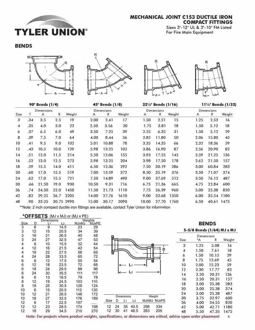
3 MECHANICAL JOINT C153 DUCTILE IRON COMPACT FITTINGS Sizes 3"-12" UL & 3"-10" FM Listed For Fire Main Equipment SAMPLE SPECIFICATIONS (Current ANSI/AWWA revisions apply) Mechanical joint watermain fittings with accessories, 2" through *64" shall be manufactured from ductile iron in accordance with and meet all applicable terms and provisions of standards ANSI/AWWA C153/A21.53 and ANSI/AWWA C111/A Ductile iron mechanical joint fittings 2" through 24" shall be rated for 350 PSI working pressure. Ductile iron 30" through 48" shall be rated for 250 psi working pressure. Flanged ductile iron fittings in 24" (610 mm) and smaller sizes may be rated for 350 psi (2,413 kpa) with the use of special (annular ring or comparable) gaskets. All coated and lined fittings meet requirements of NSF-61, NSF-372, and Annex G. NOTE - EXCEPTIONS: Mechanical joint fittings with flanged branches are rated for water pressure of 250 PSI. NOTE - Wyes over 12" are not pressure rated. Contact manufacturer for rating in your application. NOTE - Fittings are cement lined and seal coated in accordance with ANSI/AWWA C104/A Fittings are available double cement-lined, bare, or epoxy coated upon request. Epoxy coating per ANSI/AWWA C116 NOTE - Installation per AWWA C600 and AWWA C651, current revision NOMINAL JOINT DIMENSIONS IN INCHES BOLTS Size A Dia. B C Dia. D Dia. F Dia. J Dia. K 1 Dia. K 2 Dia. L M S T X Size No ¾ Á x ¾ Á.x  ¾x3½  ¾x3½  ¾x  ¾x Â. ¾x Â. ¾x4½  ¾x4½  ¾x4½  ¾x4½ Â. ¾x x x À 1¼x6½ À. 1¼x6½ 32 NOTE: 2 Inch MJ ASTM A536 ductile iron Compact fittings (2"-22.5 bend, 2"-45 bend, 2"-90 bend, 2"x12" solid sleeve, 2"x2" tee, 4"x2" tee, and 4"x2" reducer) are available. Contact Tyler Union for availability or additional product dimensions. Contact Tyler Union for 54"-64" product information. *NOTE: For projects where product weights, specifications, or dimensions are critical, advise upon order placement. 3
4
 Dimensions Dimensions Dimensions Dimensions Size T A Y R Weight A Y R Weight A Y R Weight A Y R Weight 3.34 3.5 9.0 2.5 18 2.0 7.5 2.41 17 1.50 7.00 2.51 19 1.25 6.75 7.62 15 4.35 4.0 9.5 3.")


5 MECHANICAL JOINT C153 DUCTILE IRON COMPACT FITTINGS Sizes 3"-12" UL & 3"-10" FM Listed For Fire Main Equipment BENDS 90 Bend MJ x PE (1/4) 45 Bend MJ x PE (1/8) 22½ Bend MJ x PE (1/16) 11¼ Bend MJ x PE (1/32) Dimensions Dimensions Dimensions Dimensions Size T A Y R Weight A Y R Weight A Y R Weight A Y R Weight Bend MJ x Flange 45 Bend MJ x Flange 22½ Bend MJ x Flange 11¼ Bend MJ x Flange (1/4) (1/8) (1/16) (1/32) Dimensions Dimensions Dimensions Dimensions Size T A R F Weight A R F Weight A R F Weight A R F Weight Swivel x Swivel Hydrant Ell Dimensions Size T *A *B C D E F *R **Weight ** Weight includes two swivel glands. *NOTE: _utility catalog.pdf 5 12/15/08 8:24:18 AM
6 MECHANICAL JOINT C153 DUCTILE IRON COMPACT FITTINGS Sizes 3"-12" UL & 3"-10" FM Listed For Fire Main Equipment TEES CROSS MJ Tee MJ x FE Tee MJ x Swivel Tee Cross Dimensions Weights Size T T 1 *H *J 1 *J 2 *J 3 MJ MJxFE MJxS Cross x x x x x x x x x x x x x x x x x x x x x x x x x x x x x x x NOTE: Contact TU Inside Sales representative for MJ Crosses larger than 16 inch. MJxSwl Weights include swivel gland. **NOTE: 2"x2" and 4"x2" Compact C153 tees area available, contact Tyler Union for information. 6
7 MECHANICAL JOINT C153 DUCTILE IRON COMPACT FITTINGS Sizes 3"-12" UL & 3"-10" FM Listed For Fire Main Equipment TEES (Continued) MJ GLANDS MJ Tee MJ x FE Tee MJ x Swivel Tee Dimensions Weights Size T T 1 *H *J 1 *J 2 *J 3 MJ MJxFE MJxS 20x x x x x x x x x x x x x x x x x x x x x x x x x x x x x x x x x x Glands Size Weight Size Weight Swivel Glands, page 23 Retainer Glands, page 10 Swivel x Solid Adapter with Swivel Gland Size by Wall Laying Length Thickness Weight 6x x x x Swivel x Swivel Adapter Size by Wall Laying Length Thickness Weight 6x x x x MJxSwivel Tee Weights include swivel 48x gland 48x x x x NOTE: "H" and "J" are approximate, contact Tyler Union for the dimensions of a specific fitting. 7
8 MECHANICAL JOINT C153 DUCTILE IRON COMPACT FITTINGS Sizes 3"-12" UL & 3"-10" FM Listed For Fire Main Equipment WYES/LATERAL REDUCERS ( L dimensions are approximate) *Wyes Dimensions Size *A *Y T T 1 Weights x x x x x x x x x x x t16x t16x x *Not in AWWAC153, A & Y are approximate dim. Rated at 250 psi. MJ x FE Flange Dimensions are on inside front cover. *MJ x PE x MJ Tee Dimensions Size T T 1 *H *J 1 *Z Weights x *Note: H, J, and Z are approximate, contact Tyler Union for the dimensions of a specific fitting MJ x MJ PExMJSEB MJLEBxPE PE x PE Dimensions MJ SEB LEB PE Weights Size T T 1 *L *L *L *L MJ SEB LEB PE 4x x x x x x x x x x x x x x x x x x x x x x x x x x x x x x x x x x x x x x x x x x x x x x x x x
9 MECHANICAL JOINT C153 DUCTILE IRON COMPACT FITTINGS Sizes 3"-12" UL & 3"-10" FM Listed For Fire Main Equipment SOLID & TAPPED PLUGS & CAPS SOLID SLEEVES 3"-12" 14"-24" 3"-12" 14"-24" MJ Plug MJ Cap Dimensions Max. Weights Size T Tap Plugs Caps TAPPED TEE MJ x FE Flange Dimensions are on inside front cover. Short Long Dimensions Weights Size T L 1 L 2 Short Long Note: 2"x12" C153 Sleeves available, call for information ADAPTERS MJ Tapped Tee (2" Tap) Dimensions Size T *L Max. Tap Weights MJ x FE FE x PE Dimensions Weights Size T L 1 L 2 MJxFE FExPE 3.34 * * * * * * * * * * * * *
10 DUAL PURPOSE CUTTING-IN SLEEVE MECHANICAL JOINT C153 DUCTILE IRON COMPACT FITTINGS Sizes 3"-12" UL & 3"-10" FM Listed For Fire Main Equipment MJ x FE Cutting-In Sleeve with Dual Purpose Accessories Dimensions Shipping Wt. Size For Pipe Size L L 1 T Assembled O.D O.D O.D O.D O.D Flanged ends are faced and drilled per ANSI/AWWA C110/A Mechanical joint ends are designed to receive both standard and oversize gray or ductile iron pipe as shown above. MJ x FE Flange TYPICAL CUTTING-IN SLEEVE INSTALLATIONS Dimensions are on inside front VALVE cover. INSTALLATIONS METER SETTINGS *SET-SCREW RETAINER GLAND Pipe Wall Thickness: Sizes 3"-12" are recommended for ductile iron pipe class 50 thru 56. Sizes 14" thru 24" are recommended for ductile iron pipe class 53 thru 56. DUCTILE IRON RETAINER GLANDS Mechanical Joint Retainer Glands are designed to provide a method for restraining mechanical joint pipe and **fittings and other standardized mechanical joints See Installations Instructions... Page 63 against possible joint separation, rupture or blow-out caused by internal water pressure. Pressure Gland Pipe O.D. D.I. Pipe No of Size of Rating, O.D. O.D. Wall Set Set Gland Weight The set screws are square-headed Size psi B A Class Screws Screws Weight w/acces. with Type C knurled cup points, and are shipped already assembled in the Glands Á x2 5 7 They are manufactured of 4140 grade Á x alloy steel, and are heat treated to a Rockwall Á x C 45/53 case hardness. Tee-head Á x bolts and gaskets are not included, but Á x may be ordered separately. Recommended torque for set screws is 75 foot pounds, Á x and set screws on opposite sides of the Á x2½ glands should be tightened alternately Á x2½ Tee-head bolt hole size and spacing Á x2½ are equal to MJ Glands as shown in Á x AWWA C111. Standard mechanical Joint gaskets as shown in AWWA C111 should be Á x used. * Not included in AWWA C110 **Note: Not recommended for plain end fittings 10
11 MECHANICAL JOINT DUCTILE IRON COMPACT SPLIT REPAIR GLANDS 4" Size 6"-8"-10"-12" Sizes MJ Compact Split Repair Glands Inside Diameter Bolt Circle Weight Size ( ) (+-.06) Lbs Split glands work with standard MJ gaskets and standard T-head bolts. Glands are shipped in halves and do not need separate bolts. T-head bolts alone hold the halves together. 11
12 COMPACT DUCTILE IRON MJ TAPPING SLEEVES SAMPLE SPECIFICATION (Current ANSI/AWWA revisions apply) Ductile iron mechanical joint tapping sleeves furnished by Tyler Union Waterworks are produced in accordance with manufacturer's standards. Chemical and physical properties of the ductile iron are in accordance with the requirements of ANSI/AWWA C153/A21.53 and ASTM A536. Coatings are NSF-61, NSF-372, Annex G approved and conform with AWWA C104. Flange recess dimensions per MSS SP-60. Tapping sleeve meets requirements of MSS SP-111 General Installation Instructions for Tyler Union Waterworks MJ Tapping Sleeves 1. Clean pipe - insert side gasket into back half of gasket grooves. Make sure ends are flush with or slightly protrude into the end gasket seating area. 2. Bolt sleeve halves together and trim side gaskets as necessary. MAKE SURE SLEEVE WILL ROTATE FREELY ON PIPE. 3. Install end gaskets, locating cut ends 90 from side gasket. If pipe is maximum OD, stretch gasket to make certain cut ends match with no gap in between. 4. Install glands and bolts - rotate sleeve to desired position. Be sure pipe is centered inside the sleeve. 5. Tighten gland bolts alternately, using 80 to 90 foot pounds. 6. After assembly, PRESSURE TEST ALL JOINTS BE- FORE TAPPING. If additional tightening is required, release pressure and relax tension on gland bolts before tightening side bolts. For Cast Iron, Ductile Iron, and PVC C900 Pipe Mechanical joint tapping sleeves - for 6" through 12" cast iron, ductile iron, or PVC pipe. Outlet flange per ANSI/AWWA C153/A21.53 Gaskets furnished meet AWWAC111 and ASTM D2000-AA. Working pressure-250 p.s.i. Gaskets available in SBR only Joint deflection is not recommended Tapping Sleeve for Cast Iron/Ductile Iron O.D. Range Dimensions DI Weight Size A B C D E F Min. Max. DI 6x x x x x x x x x x
13 DUCTILE IRON C110 FULL BODY MECHANICAL JOINT DIMENSIONS Sizes 3" thru 12" UL Listed for Fire Main Equipment SAMPLE SPECIFICATION (Current ANSI/AWWA revision apply) Mechanical joint watermain fittings with accessories, 2" through 48" shall be produced of ductile iron in accordance with and meet all applicable terms and provisions of standards ANSI/AWWA C110/A21.10 and ANSI/AWWA C111/A Ductile iron mechanical joint fittings 3" through 24" shall be rated for 350 PSI working pressure. All ductile iron mechanical joint fittings 30" through 48" shall be rated for 250 PSI working pressure. Flanged ductile-iron fittings in 24-in. (610mm) and smaller sizes may be rated for 350 psi (2,413 kpa) with the use of special (annular ring or comparable) gaskets. NOTE - EXCEPTIONS: Mechanical Joint Fittings with flanged branches and 14" and larger caps and plugs are rated for water pressure of 250 PSI. NOTE - Installation per AWWA C600 and AWWA C651, current revision NOTE: Fittings are cement lined and seal coated in accordance with ANSI/AWWA C104/A21.4. Fittings are also available double cement lined, bare or epoxy coated. Coated and lined fittings meet requirements of NSF-61, NSF-372, & Annex G.. NOMINAL JOINT DIMENSIONS IN INCHES - MECHANICAL JOINT FITTINGS DIMENSIONS IN INCHES Size A B C D F Ø X J K 1 K 2 L M N O P S * ¾ ¾ Â Â Â Â Â Â Â Â Â Â À À * Not included in AWWA C110. ACCESSORIES AND WEIGHTS 14" THRU 48" GLANDS MAY Wt. of Gland, Pipe BE TAPERED Bolt Bolt Bolt Torque Bolts and Barrel Size No. Size Length Ft/Lbs. Gasket, Lbs. O.D. *2 2 Á Á ¾ 3½ ¾ 3½ ¾ ¾ ¾ ¾ 4½ ¾ 4½ ¾ 4½ ¾ 4½ ¾ ¼ 6½ ¼ 6½ * Not included in AWWA C110. ANSI/AWWA C110/A21.10, ANSI/AWWA C111/A

14 DUCTILE IRON C110 FULL BODY MECHANICAL JOINT FITTINGS MJ x FIPT ECCENTRIC REDUCER Dimensions Size L Weights 6x x BENDS 90 MJ x MJ (1/4) 90 MJ x PE (1/4) 90 MJ x FE (1/4) 90 Bends (1/4) Dimensions Weights Size R Y Z MJxMJ MJxPE MJxFE * Mechanical Joint weights do not include Glands, Nuts, Bolts and Gaskets. See Joint Accessories. For sizes not found in this section check MJ-SSB DI fittings, pages 3 thru 11. ANSI/AWWA C110/A21.10, ANSI/AWWA C111/A
15 DUCTILE IRON C110 FULL BODY MECHANICAL JOINT FITTINGS BENDS 45 MJ (1/8) 45 MJ x PE (1/8) 45 MJ x FE (1/8) 22½ MJ (1/16) 22½ MJ x PE (1/16) 22½ MJ x FE (1/16) 45 Bends (1/8) Dimensions Weights Size R Y Z MJ MJxFE* MJxPE * * Not included in AWWA C ½ Bends (1/16) Dimensions Weights Size R Y Z MJ MJxFE* MJxPE ¼ Bends (1/32) Dimensions Weights Size R Y Z MJ MJxFE* MJxPE ¼ MJ (1/32) 11¼ MJ x PE (1/32) ¼ MJ x FE (1/32) ANSI/AWWA C110/A21.10, ANSI/AWWA C111/A
16 DUCTILE IRON C110 FULL BODY MECHANICAL JOINT FITTINGS MJ TAPPED TEE MJ Tapped Tee (2"Tap) Dimensions Size L Max. Tap Weights For sizes not found in this section check MJ-SSB DI fittings, pages 3 thru 11. TEES Straight Tees and Reducing on Branch Tees Bullhead MJxMJxFE Size Dimensions Weights Run Run Branch X Y Z MJ **MJxPExMJ **MJxMJxFE * * * * * NOTICE: Weights published in this catalog are for shipping purposes only. Actual weights may vary because some fittings are produced in multiple foundries. All fittings meet the AWWA standards to which they are designed. For weights of specific fittings, please contact Tyler Union Waterworks Company. *Not included in AWWA C110 **Made to order only. Not Returnable ANSI/AWWA C110/A21.10, ANSI/AWWA C111/A
17 DUCTILE IRON C110 FULL BODY MECHANICAL JOINT FITTINGS TEES (Con't) Straight Tees and Reducing on Branch Tees Bullhead MJxMJxFE Size Dimensions Weights Run Run Branch X Y Z MJ **MJxPExMJ **MJxMJxFE * Not included in AWWA C110 ** Made to order only. Not Returnable ANSI/AWWA C110/A21.10, ANSI/AWWA C111/A
18 DUCTILE IRON C110 FULL BODY MECHANICAL JOINT FITTINGS WYES/LATERAL ( Not included in AWWA C110.) CROSSES Size Dimensions Run Branch X Z Weights For sizes not found in this section check MJ-C153 sec ALL MJ *MJ x MJ x FE x FE Size Dimensions Weights Run Branch X Y MJ *MJxFE *Not included in AWWAC110. ANSI/AWWA C110/A21.10, ANSI/AWWA C111/A
19 DUCTILE IRON C110 FULL BODY MECHANICAL JOINT FITTINGS REDUCERS Laying Lengths (L) Weights Size MJ MJ-SEB MJ-LEB PExPE FExMJ MJxFE MJ MJ-SEB MJ-LEB PExPE FExMJ MJxFE * 3x * 4x x * 6x x MJ Reducer 6x x x x x x x x x MJ Small End Bell Reducer 12x x x x x x x x x MJ Large End Bell Reducer 18x x x x x x x x x Plain End-Plain End Reducer 24x x x x *30x x x x x FExMJ Reducer 36x x x x x x x x * Not included in AWWA C110 MJxFE Reducer ANSI/AWWA C110/A21.10, ANSI/AWWA C111/A


20 DUCTILE IRON C110 FULL BODY MECHANICAL JOINT FITTINGS SOLID SLEEVES Standard Pipe Short Long Size O.D. L Weight L Weight * * Not included in AWWA C110 * Dual Purpose Pipe Short Long Size O.D. L Weight L Weight / / / / / / All Sizes Use MJ Dual Purpose Gland * Not included in AWWA C110 12" & 16" are sold assembled NOTE: Sizes 4-10" use standard MJ Gaskets; 12" and 16" require special duo gaskets. * MJ x PE DUAL-PURPOSE CUTTING-IN SLEEVE With Dual-Purpose Accessories (NOTES: Gland with cup-joint set screws available at extra cost when specified. NOT FOR RESTRAINT.) Currently, Tyler and Union Dual Purpose Glands are NOT interchangeable. Cutting-In Sleeve & Gland Weight For Use Gland Gland Size On Pipe O.D. L L 1 D Only & Sleeve * Not included in AWWA C110. ADAPTERS MJ x FE Dimensions Size L Weights ANSI/AWWA C110/A21.10, ANSI/AWWA C111/A


 Size Tap Weight 14 2.0 101 16 2.0 137 18 2.0 177 20 2.0 239 24 2.")
21 DUCTILE IRON C110 FULL BODY MECHANICAL JOINT FITTINGS PLUGS CAPS OFFSETS Solid or Tapped Weight Size Tap Solid Tapped * Dished Not flat as shown. * Not included in AWWA C110. Solid or Tapped Weight Size Tap Solid Tapped * Dished Not flat as shown. * Not included in AWWA C110. MJ x MJ MJ x PE Dimensions Weights Size D L 1 L MJxMJ MJxPE * * * * * * * Not included in AWWA C110. TYTON Plug** Solid or Tapped Size Tap T Weight* * Weights do not include accessories ** Not included in AWWA C110. TYTON is a registured trademark of U.S. Pipe and Foundry Company. Solid Tapped Push-In Plug with Ears (To be used with all push-in pipe and fittings) Size Tap Weight Dished - Not flat as shown NOTE: Blocking still required ears for assembly only. ANSI/AWWA C110/A21.10, ANSI/AWWA C111/A
22 DUCTILE IRON C110 FULL BODY MECHANICAL JOINT FITTINGS TEES *SET-SCREW RETAINER GLAND See Installations Instructions... Page 63 Pressure Gland Pipe O.D. D.I. Pipe No of Size of Rating, O.D. O.D. Wall Set Set Gland Weight Size psi B A Class Screws Screws Weight w/acces Á x Á x Á x Á x Á x Á x Á x2½ Á x2½ Á x2½ Á x Á x * Not included in AWWA C110 Pipe Wall Thickness: Sizes 3"-12" are recommended for ductile iron pipe class 50 thru 56. Sizes 14" thru 24" are recommended for ductile iron pipe class 53 thru 56. DUCTILE IRON RETAINER GLANDS Mechanical Joint Retainer Glands are designed to provide a method for restraining mechanical joint pipe and **fittings and other standardized mechanical joints against possible joint separation, rupture or blow-out caused by internal water pressure. The set screws are square-headed with Type C knurled cup points, and are shipped already assembled in the Glands. They are manufactured of 4140 grade alloy steel, and are heat treated to a Rockwall C 45/53 case hardness. Tee-head bolts and gaskets are not included, but may be ordered separately. Recommended torque for set screws is 75 foot pounds, and set screws on opposite sides of the glands should be tightened alternately. Tee-head bolt hole size and spacing are equal to MJ Glands as shown in AWWA C111. Standard mechanical Joint gaskets as shown in AWWA C111 should be used. **Note: Not recommended for use on plain end fittings MJ GLAND Gland Weight Size Wt. Pack Gland Only MJ x MJ x Swivel Dimensions Size X Y Weight x x x x x x All weights shown include the Swivel Gland 42 Call Call 341 ANSI/AWWA C110/A21.10, ANSI/AWWA C111/A


23 DUCTILE IRON C110 FULL BODY MECHANICAL JOINT ELLS, ADAPTERS AND GLANDS For Valve and Hydrant Connections ADAPTERS Swivel x Solid Adapter Size by Wall Laying Length Thickness Weight* 4x x x x x x x * Weights with Gland. Other Swivel Hydrant Fittings, Pages 5, 6 and 7. ELLS *90 Swivel x Swivel Ell (Not Included In AWWA C110) Wall Dimensions Size Thickness A B C D E F R *Weight * With 2 Swivel Glands SWIVEL GLAND ASSEMBLY Used with swivel fittings, the TYLER UNION Swivel gland, with its rotating feature, permits the installer to meet any grade requirements regardless of bolt-hole alignment. In addition, the system permits stiff connections without braces, blocking or strapping. Swivel Glands** Size Weight ** Not included in AWWA C110. NOTE: When ordering glands separately, (1) Specify TYLER UNION UPCode Number, (2) Description, and (3) Size of fitting to be joined. ANSI/AWWA C110/A21.10, ANSI/AWWA C111/A
24 UNION-TITE DUCTILE IRON C153 COMPACT FITTINGS Sizes 4"-12" UL Listed for Fire Main Equipment SAMPLE SPECIFICATIONS (Current ANSI/AWWA revisions apply) 4" through 24" Push-On joint ductile iron fittings shall be produced in accordance with all applicable terms and provisions of ANSI/AWWA C153/A Fittings are cement-lined and seal-coated in accordance with ANSI/AWWA C104/A21.4. Joints shall be in accordance with manufacturer's design with bell sockets designed to receive pressure pipe O.D.'s as specified in ANSI/AWWA C151/A21.51 and AWWA C900 TABLE 2. The working pressure rating shall be 350 PSI, except for wyes and flanged-branch fittings. NOTE: Fittings are cement lined and seal coated in accordance with ANSI/AWWA C104/A21.4, also available bare or epoxy coated. Double cement lined available. Coated and/or lined fittings meet NSF-61, NSF-372 and Annex G. Thicknesses and dimensions of bell sockets and gaskets shall be in accordance with the manufacturer's design. Gaskets shall be furnished by the manufacturer. Working pressures apply to fittings only and do not apply to restraining lugs or external restraining devices. Installation of fittings shall be per AWWA C600 and AWWA C651, current revision. NOTE: Standard restraining lugs are provided on sizes 4" through 16" ONLY. Restraining lugs are available on 18"-24" fittings provided sufficient time is available to make tooling adaptations. EXCEPTIONS: Union-Tite fittings with flanged branches are rated for water pressure of 250 PSI but can be rated for 350 PSI with the use of an annular ring or comparable gasket. Wye fittings over 12" are not pressure rated, call Tyler Union for information. ADVANTAGES AND FEATURES Push-on gasket joint uses TYTON or McWane 350 Sure Stop gaskets For use with Ductile iron pipe, C-900/905 PVC pipe, and 4"-12" pressure rated IPS diameter PVC pipe (with transition gasket) Deep stab joint design accommodates common spigot end taper on plastic pipes Slip joint installation eliminates T-bolts and nuts (MJ glands not needed) BELL DIMENSIONS IN INCHES FOR UNION-TITE FITTINGS Pipe Size A B B.C. C D E TYTON is a registered trademark of U.S. Pipe and Foundry Company. For Joint deflection, refer to Tyler Union product submittal 26U located on page 65 of this catalog. 1191CR 492 Tyler, Texas (800)
25 UNION-TITE DUCTILE IRON C153 COMPACT FITTINGS Sizes 4"-12" UL Listed for Fire Main Equipment BENDS 90 (1/4) UT Bends 45 (1/8) UT Bends 22½ (1/16) UT Bends 11¼ (1/32) UT Bends Dimensions Dimensions Dimensions Dimensions Size T *A *R Weight *A *R Weight *A *R Weight *A *R Weight (1/4) 45 (1/8) 22½ (1/16) 11¼ (1/32) UT x Flange Bends UT x Flange Bends UT x Flange Bends UT x Flange Bends Dimensions Dimensions Dimensions Dimensions Size T *A *B *R Weight *A *B *R Weight *A *B *R Weight *A *B *R Weight NOTE: A, B, and R dimensions are approximate, contact Tyler Union Waterworks for the dimensions of a specific fitting _utility catalog.pdf 25 12/15/08 8:24:25 AM
26 UNION-TITE DUCTILE IRON C153 COMPACT FITTINGS BENDS 90 (1/4) 45 (1/8) 22½ (1/16) 11¼ (1/32) UT x PE Bends UT x PE Bends UT x PE Bends UT x PE Bends Dimensions Dimensions Dimensions Dimensions Size T A B R Weight A B R Weight A B R Weight A B R Weight TEES UT x UT x PE Tees Size Dimensions Run Branch T T1 H J3 Weight
27 UNION-TITE DUCTILE IRON C153 COMPACT FITTINGS TEES UT x UT Tees UT x Flange Tees UT x Swivel Tees Dimensions Weights Size T T1 *H *J1 *J2 *J3 UT x UT UT xflange UT x Swivel x x x x x x x x x x x x x x x x x x x x x x x x x x x x x x x x x x x NOTE: H and J dimensions are approximate, contact Tyler Union Waterworks for dimensions of a specific fitting _utility catalog.pdf 27 12/15/08 8:24:25 AM
28 UNION-TITE DUCTILE IRON C153 COMPACT FITTINGS REDUCERS TAPPED TEE/CROSS UT x UT Reducers UT x Flange Reducers Dimensions Weights Size T T1 *L *G UT x UT UT xflange 6x x x x x x x x x x x x x x x x x x x x x x x x x x x x x x x x x x UT x Flange Adaptor Dimensions Size T *L Weight Solid Cap UT x Tapped Tee/Crosses Dimensions Size T Max Tap *L Weight CAPS AND PLUGS UT Caps and Plugs* Solid Plug 2" Tapt Cap 2" Tapt Plug Dimensions Weights Size T1 T2 *L Cap Plug *Restraining lugs (ears) available. NOTE: G and L dimensions are approximate, contact Tyler Union Waterworks for dimensions of a specific fitting _utility catalog.pdf 28 12/15/08 8:24:26 AM
29 UNION-TITE DUCTILE IRON C153 COMPACT FITTINGS WYES CROSSES UT Wyes Dimensions Size T T1 P N Weights 8x x x x x x x x x x x x x x UT Crosses Dimensions Size T1 H J Weights x x x x x x x x x x x x TYTON GASKETS NOTICE: Weights published in this catalog are for shipping purposes only. Actual weights may vary because some fittings are produced in both foundries. All fittings are made in the USA and meet TYTON JOINT IPS Transition and Regular Gasket the AWWA standards to which they are Dimensions designed. Transition (IPS) Regular (Ductile) Size A B(±1%) For weights of specific fittings, please B* C contact your Tyler Union Waterworks representative TYTON is a registered trademark of U.S. Pipe and Foundry Company. 29
30 DUCTILE IRON C110 FLANGED FITTINGS Sizes 3" thru 12" UL Listed for Fire Main Equipment SAMPLE SPECIFICATION (Current ANSI/AWWA revisions apply) Flanged fittings, 2" through 48" shall be manufactured of ductile Iron in accordance with all applicable terms and provisions of standards ANSI/AWWA C110/A Flange surfaces shall be faced and drilled in accordance with ANSI Class 125, B16.1. All ductile iron flanged fittings shall be rated for water pressure of 250 PSI. Flanged ductile-iron fittings in 24-in. (610 mm) and smaller sizes may be rated for 350 psi (2,413 kpa) with the use of special gaskets. NOTE: Fittings are cement lined and seal coated in accordance with ANSI/AWWA C104/A21.4. Fittings are also available prime coated, bare or epoxy coated. All coated fittings meet requirements of NSF-61, NSF-372, and Annex G. Interiors of fittings shall be lined and seal coated in accordance with ANSI/AWWA C104/A21.4. Cement mortor lining for ductile iron pipe and fittings for potable water unless otherwise specified. Installation of fittings shall be per AWWA C110. NOTE: No flange joint material furnished. FLANGE DETAILS Nominal Dia. of Flange Pipe Size Flange Bolt Thickness Bolt Hole Number Bolt Dia. Inch O.D. Circle T Diameter of Bolts and Lengths Á x 2¼ Á x 2½ Á x ¾ x 3½ ¾ x 3½  x  x x 4½ x 4½ x x ¼ x 5½ ¼ x 6½ ½ x ½ x 7½ ½ x 8 NOTE: Drilling templates are in multiples of four, so that fittings may be made to face in any quarter. Bolt holes shall straddle the center line. 30
31 DUCTILE IRON C110 FLANGED FITTINGS Sizes 3" thru 12" UL Listed for Fire Main Equipment BENDS Note: Base Bends are on page 33 and 34, reducing and long radius 90 bends are on page Bends (1/4) 45 Bends (1/8) 22 1 / 2 Bends (1/16) 11 1 / 4 Bends (1/32) Dimensions Dimensions Dimensions Dimensions Size R A Weight R A Weight R A Weight R A Weight
32 DUCTILE IRON C110 FLANGED FITTINGS TEES, REDUCING TEES, CROSSES Straight Tees, Reducing *Reducing *Reducing on *Bullhead Straight and on Branch Tees on Run Run and Branch Tees Reducing Crosses Size Dimensions Weights Run Run Branch H J Tee Cross * * * * * * * * * * * * * * * * * * Size Dimensions Weights Run Run Branch H J Tee Cross * * * * * * Not included in AWWA C110 H and J dimensions are two-inches longer than straight tees. 32
33 DUCTILE IRON C110 FLANGED FITTINGS TEES, REDUCING TEES, CROSSES (Con't) Size Dimensions Weights Run Run Branch H J Tee Cross * * Not included in AWWA FLANGE AND FLARE *Flange and Flare 90 Ell Dimensions Size D X Y Weight *Flange and Flare Piece Dimensions Size D L Weight *Flange by Flare not included in AWWA C110 33
34 DUCTILE IRON C110 FLANGED FITTINGS REDUCERS Concentric Reducer Eccentric Reducer Size Dimensions Wts D D 1 L Size Dimensions Wts D D 1 L Size Dimensions Wts D D 1 L Size Dimensions Wts D D 1 L NOTE: Eccentric Reducers not included in AWWA C110 NOTE: Eccentric Reducers Offset 1/2 D minus 1 /2 D 1 =Offset Example: 6x3 Ecc.Reducer 3-1½ = 1½" Offset 34
35 DUCTILE IRON C110 FLANGED FITTINGS * WYES/LATERALS BENDS *45 Wye Size Dimensions Run Branch H J Weight * Not included in AWWA C110 True Wye Size Dimensions Stem Branch X Y Weight BASE BENDS BASE TEES 90 Base Bend (1/4) *90 Long Radius Base Bend (1/4) Base Tees Base Bends are made to order only, not returnable. Bases are furnished faced and drilled. *90 Reducing Bend (1/4) Dimensions Size A Weight 4x x *90 Long Radius Bend (1/4) Dimensions Size R A Weight x x x x x x x * Not included in AWWA C110 14x x * Not included in AWWA C110 Support Dimensions Pipe Weight Size X S U Size LR Tee * Not included in AWWA C110 35
36 DUCTILE IRON C110 FLANGED FITTINGS * REDUCING BASE BENDS * FLANGE SLUDGE SHOE Base Under Large End FLANGES (COMPANION FLG) Flange for Steel Pipe Reducing Flange for Steel Pipe Base Under Small End Dimensions Size X S U Weight 4x x x x x x x x x * Not included in AWWA C110 NOTE: X dimensions are identical on Baseunder-large-end and Base-under-small-end. S dimensions are determined by the largest fitting opening. Flange for DI Pipe Reducing Flange for DI Pipe (If Required) Under 12" Blind Flange With Optional 2" Taps 12" and Larger Blind Flange With Optional 2" Taps Flange Sludge Shoe Dimensions Size D X Y Weight * Not included in AWWA C110 Base Drilling Details Nom. Dimensions - Inches Diameter Bolt Hole Number Inches BC Diameter of Bolts / / / / / / / / / / / / /4 4 Dimensions Weight Size O Q Y Z Steel DI Blind Blind Tap ½ NOTE: All flanges conform to ANSI/AWWA C110/A21.10 Standards. DI Reducing Flange DI Reducing Flange Threaded For Steel Pipe Threaded For Cast Iron Pipe Size Tap x O.D. Weight Size Tap x O.D. Weight 4x3 3x9 16 4x3 3x9 16 6x4 4x x4 4x x4 4x13½ 44 8x4 4x13½ 40 8x6 6x13½ 31 8x6 6x13½ 35 10x6 6x x8 8x x6 6x x8 8x x8 8x x10 10x19 72 *NOTE: "X" and "Y" dimensions are approximate, contact Tyler Union for these dimensions of a specific fitting 36
37 DUCTILE IRON C110 FLANGED FITTINGS ADAPTER FLANGES (EZ OR UNI) See Index for Installation Instructions Rated No. of No. of Bolt Working Set Bolt Bolt & Size Hole Size Pressure Screws Circle Nuts of Bolt Dia Á x2½ ¾ Á x3 ¾ ¾x3½  ¾x3½   x  x4 1 DUCTILE IRON ADAPTER FLANGE Ductile Iron D F C Pipe OD Size +.06 or Weight All set screws are 5 / 8 " 80 lb. torque head. Wall Thickness Note: Recommended for Ductile Iron Pipe Class 53 thru Class 56. **LOCATION OF TAPPED HOLES FOR DRAINS AWWA C110 Flanged Fittings Fittings can be supplied with taps sized and located to ANSI B16.1 and MSS-SP-45. Specify fitting size, tap location by letter (refer to drawings) and tap size by NPT dimension, on order. NOTE: A BOSS IS ALWAYS REQUIRED AT Y OR V ON STRAIGHT AND REDUCING SIZES OF 90-DEGREE ELBOWS, AND ON TAPERED SIDES OF REDUCERS. Fitting Size Maximum Tap Fitting Fitting Size Size Maximum Tap Tap Without Boss Boss 3"...1/2" 4" - 6"...3/4" 8"...1-1/4" 10" - 16"...1-1/2" 18" - 36"...2" ADDER for Tapping & Extra Heavy 250 Class Flange Policy: For pricing of tapped outlets, tapped for studs, and extra heavy 250 Class C110 flanged fittings; refer to List Price Guide or consult your Tyler Union Inside Sales Representative for current pricing and more details. **NOTE: For additional tapping options contact the Tyler Union Waterworks Inside Sales Representative for your State. 37
38
39 **6850 SERIES CAST IRON TWO-PIECE VALVE BOXES for 4" through 12" valves, 5 1 /4" shaft, screw-type TYLER UNION valve boxes are available either pre-assembled or as individual tops and bottoms. For assembled boxes, The UPC codes shown represent a combination of one top and one bottom in the sizes shown. For unassembled boxes, the UPC code represents only a top or a bottom, not a complete box. Therefore, unassembled boxes require ordering tops and bottoms separately. **NOTE: Domestic Valve Boxes available in Heavy Duty Only Non-Domestic available in Standard or Heavy Duty Box Assembled (Less Lid) Extension *(D-HD)UPCode *(ND-HD)UPCode *(ND-Std.)UPCode Box (Components) Height Wt Wt 461-S (10T + 15B) S (10T + 24B) S (16T + 24B) S (16T + 30B) S (16T + 36B) S (26T + 30B) S (26T + 36B) S (26T + 24B) S (26T+24B+60 Ext) S (26T+36B+60 Ext) NOTE: D=Domestic ND=Non-Domestic HD=Heavy Duty Weight Std.=Standard Weight Lids marked WATER will ship unless otherwise specified: Also available 5¼" Drop Lids" 1)WATER OMA 2)SEWER 3)MWW 4)PLAIN 5)GAS 6)REUSE Note: Special Lettering Available Contact Tyler Union for Setup Charge 39
40 6850 SERIES CAST IRON TWO-PIECE VALVE BOXES for 4" through 12" valves, 5 1 /4" shaft, screw-type SEPARATE UPCODES for VALVE BOX TOPS ONLY (Less Lids) TOP **(D-HD) UPCode **(ND-HD) UPCode **(ND-Std.) UPCode Box Length Wt Wt Wt 461-S (10T) S (10T) S (16T) S (16T) S (16T) S (26T) S (26T) S (26T) S (26T) **NOTE: D=Domestic ND=Non-Domestic HD=Heavy Duty Weight Std.=Standard Weight EXTENSIONS Height **(D-HD) UPCode **(ND-Std.) UPCode Item/Description Increase Wt Wt #58 Screw-Type #59 Screw-Type #60 Screw-Type Extension SEPARATE UPCODES for VALVE BOX BOTTOMS ONLY 58 and 59 Extension Bottom **(D-HD)UPCode **(ND-HD)UPCode **(ND-Std.)UPCode Box Length Wt Wt Wt 461-S (15B) S (24B) S (24B) S (30B) S (36B) S (30B) S (36B) S (24B) S (36B) (48B) (60B) **Note: D=Domestic ND=Non-Domestic HD=Heavy Duty Weight Std.=Standard Weight 40
41 6855 SERIES CAST IRON TWO-PIECE VALVE BOXES for 4" through 12" valves, 5 1 /4" shaft, slip-type TYLER UNION valve boxes are available either pre-assembled or as individual tops and bottoms. For assembled boxes, The UPC codes shown represent a combination of one top and one bottom in the sizes shown. For unassembled boxes, the UPC code represents only a top or a bottom, not a complete box. Therefore, unassembled boxes require ordering tops and bottoms separately. **NOTE: Domestic Valve Boxes available in Heavy Duty Only Non-Domestic available in Standard or Heavy Duty Box Assembled (Less Lid) Extension *(D-HD)UPCode *(ND-HD)UPCode *(ND-Std.)UPCode Box (Components) Height Wt Wt 461-A (10T + 15B) A (10T + 24B) A (16T + 24B) A (16T + 30B) A (16T + 36B) A (26T + 30B) A (26T + 36B) A (26T+24B+60 Ext) A (26T+36B+60 Ext) NOTE: D=Domestic ND=Non-Domestic HD=Heavy Duty Weight Std=Standard Weight Lids marked WATER will ship unless otherwise specified: Also available 5¼" Drop Lids" 1)WATER OMA 2)SEWER 3)MWW 4)PLAIN 5)GAS 6)REUSE Note: Special Lettering Available Contact Tyler Union for Setup Charge 41
42 6855 SERIES CAST IRON TWO-PIECE VALVE BOXES for 4" through 12" valves, 5 1 /4" shaft, slip-type SEPARATE UPCODES for VALVE BOX TOPS ONLY (Less Lids) TOP **(D-HD) UPCode **(ND-HD) UPCode **(ND-Std.) UPCode Box Length Wt Wt Wt 461-A (10T) A (10T) A (16T) A (16T) A (16T) A (26T) A (26T) A (26T) A (26T) **NOTE: D=Domestic ND=Non-Domestic HD=Heavy Duty Weight Std=Standard Weight EXTENSIONS Height **(D-HD) UPCode **(ND-Std.) UPCode Item/Description Increase Wt Wt #58-A Slip-Type 6 to #59-A Slip-Type 6 to #60-A Slip-Type 6 to A Extension 58-A and 59-A Extension SEPARATE UPCODES for VALVE BOX BOTTOMS ONLY Bottom **(D-HD) UPCode **(ND-HD) UPCode **(ND-Std.) UPCode Box Length Wt Wt Wt 461-A (15B) A (24B) A (24B) A (30B) A (36B) A (30B) A (36B) A (24B) * * * A (36B) * * * (60B) **NOTE: D=Domestic ND=Non-Domestic HD=Heavy Duty Weight Std=Standard Weight *NOTE: Whe installing thes extensions a 6850 screw type bottom is required 42
43 6860 SERIES CAST IRON THREE-PIECE VALVE BOXES for 3" through 20" valves, 5 1 /4" shaft, screw-type ***(Base required, order separately) TYLER UNION valve boxes are available either pre-assembled or as individual tops and bottoms. For assembled boxes, The UPC codes shown represent a combination of one top and one bottom in the sizes shown. For unassembled boxes, the UPC code represents only a top or a bottom, not a complete box. Therefore, unassembled boxes require ordering tops and bottoms separately. **NOTE: Domestic Valve Boxes available in Heavy Duty Only Non-Domestic available in Standard or Heavy Duty Base Illustrated For Position Only... Not Furnished. Box Assembled (Less Lid) Extension *(D-HD)UPCode *(ND-HD)UPCode *(ND-Std.)UPCode Box (Components) Height Wt Wt AA (10T + 12B) A (16T + 18B) B (16T + 24B) C (16T + 30B) CC (16T + 36B) D (26T + 30B) DD (26T + 36B) E (16T+24B+60 Ext) F (26T+24B+60 Ext) G (26T+36B+60 Ext) Lids marked WATER will ship unless otherwise specified: Also available 5¼" Drop Lids" 1)WATER OMA 2)SEWER 3)MWW 4)PLAIN 5)GAS 6)REUSE Note: Special Lettering Available Contact Tyler Union for Setup Charge *NOTE: D=Domestic ND=Non-Domestic HD=Heavy Duty Weight Std=Standard Weight ***NOTE: Base Selection Guide (#4 Base for 6 valves or less) (#6 Base for 12 valves or less) (#160 Base for 24 valves or less) 43
44 6860 SERIES CAST IRON THREE-PIECE VALVE BOXES for 3" through 20" valves, 5 1 /4" shaft, screw-type (Base required, order separately) SEPARATE UPCODES for VALVE BOX TOPS ONLY (Less Lids) TOP **(D-HD) UPCode **(ND-HD) UPCode **(ND-Std.) UPCode Box Length Wt Wt Wt AA (10T) A (10T) B (16T) C (16T) CC (16T) D (26T) DD (26T) E (16T) F (26T) G (26T) **NOTE: D=Domestic ND=Non-Domestic HD=Heavy Duty Weight Std.=Standard Weight 58 and 59 Extension 60 Extension #4 Base #6 Base (Standard) #160 Base EXTENSIONS BASES UPCode Height *(D-HD)UPCode *(ND)UPCode *(ND-Std)UPCode Item/Description Increase Wt Item/Description Wt Wt #58 Screw-Type #4, 11¼ Wide #59 Screw-Type #6, 14¾ Wide #60 Screw-Type #160, 20½ Wide #60 Screw-Type * *D=Domestic ND=Non-Domestic HD=Heavy Duty Weight Std.=Standard Weight #60 Screw-Type * Call *Non-Domestic SEPARATE UPCODES for VALVE BOX BOTTOMS ONLY Bottom **(D-HD) UPCode **(ND-HD) UPCode **(ND-Std.) UPCode Box Length Wt Wt Wt AA (12B) A (18B) B (24B) C (30B) CC (36B) D (30B) DD (36B) E (24B) F (24B) G (36B) (48B) (60B) **NOTE: D=Domestic ND=Non-Domestic HD=Heavy Duty Weight Std=Standard Weight 44
UPCode 670610")
UPCode *(ND-HD)UPCode Special 670610 670610 Markings Wt.")

 *(D-HDUP)Code *(ND-Std)UPCode *(ND-HD)UPCode Item/Description 670610 Wt 670610 Wt 670610 Wt 5¼ Drop Lid 145325")
UPCode")
45 STANDARDSPECIAL 5¼" MWW DROP LID *(D-HD)UPCode *(ND-HD)UPCode Wt *D=Domestic ND=Non-Domestic HD=Heavy Duty Weight Drop Lid Lock Lid RECLAIMED WATER LID *(D-HD)UPCode NOTE: Square Valve Box Tops for this Lid will be available in Call Tyler Union for information. *D=Domestic HD=Heavy Duty Weight 5¼" OMA DROP LID** *(D-HD)UPCode *(ND-HD)UPCode Special Markings Wt **WATER OMA 12 *D=Domestic ND=Non-Domestic HD=Heavy Duty wt. **OMA marking is inside lid. 1 1 /8" Lid WRENCH Fits Standard Waterworks Pentagon Head 27/32" Brass Screws UPCode Ship Code Description Wt S Wrench 0.5 LIDS (WATER) *(D-HDUP)Code *(ND-Std)UPCode *(ND-HD)UPCode Item/Description Wt Wt Wt 5¼ Drop Lid ¼ Lock Lid Lid** (Use with 1 Riser Only) *NOTE: D=Domestic ND=Non-Domestic HD=Heavy Duty Weight Std=Standard Weight 5¼" DROP LID W/SPECIAL MARKINGS** *(D-HD)UPCode *(ND-Std)UPCode Special Wt Wt. Mark GAS SEWER PLAIN REUSE **Lids marked with WATER will be shipped unless otherwise specified. 45
46
47 METER COVERS, TOUCH-READER (TR) RINGS & LIDS 6150 & 6150TR METER COVERS, CAST IRON Description A B C 18-in Series 8¾ in ¾ Meter Box Cover UPCode Ship Code Description Weight S Ring & Lid B/L* S Ring & Lid B/S* S Ring Only S /20 Lid With Lock B/L* S 6150-L-18/20 Lid Less Lock S /20 Lid With Lock B/S* S Ring & Lid B/L* S Ring & Lid B/S* S 6150-R-20 Ring Only 29 *B/L = Large Head Bolts (1-1/32"); *B/S = Small Head Bolts (27/32" Standard) NOTE: The B/L & B/S pentagon head screws use the same worm or locking gear. 6150TR Meter Cover 6150TR (TOUCH-READER) METER COVERS CAST IRON UPCode Ship Code Description Weight S TR Ring & Lid B/L S TR Ring & Lid B/S* S /20 TR Lid With Lock B/L* S /20 TR Lid With Lock B/S* S /20 TR Lid Less Lock S TR Ring & Lid B/L* S TR Ring & Lid B/S* 41 *B/L = Large Head Bolts (1-1/32"); B/S = Small Head Bolts (27/32") NOTE: 6150TR - Same dimensions as 6150, plus a 1-27/32" access hole in lid. NOTE: The B/L & B/S pentagon head screws use the same worm or locking gear METER COVER, CAST IRON UPCode Ship Code Description Weight S 6200 Ring & Lid Less Lock S 6200-R Ring Only S 6200-L Lid Less Lock S 6200-L Lid With Lock Meter Cover WRENCH Fits Standard Waterworks Small Pentagon Head 27/32" Brass Screws UPCode Ship Code Description Weight S Wrench
48 ASSEMBLY INSTRUCTIONS ADAPTER FLANGE FM APPROVED Wall Thickness Note: Recommended for ductile iron pipe Class 53 thru Class Place adapter flange and MJ gasket over the plain end of the pipe with the small side of the MJ gasket facing the flange side of the adapter flange. 2. Place the pipe end against flange to be joined and slip the MJ gasket into position against the flange. Make sure the gasket is evenly seated against the flange. 3. Slide adapter flange into position against the small (tapered) side of the MJ gasket and align the bolt holes. Insert the bolts and finger tighten the nuts to maintain position and alignment. 4. Snug up all nuts evenly. 180, tighten the nuts to a torque of: 3" - 60 foot pounds; 4" thru 12" - 90 foot pounds. 5. Snug up all set screws evenly around the pipe. Tighten the Torque Head Set Screws evenly, alternating at 180 degrees. NOTE: THE TORQUE HEAD TOP WILL BREAK OFF AT THE RECOMMENDED SETTING OF FT. LBS. MAXIMUM DEFLECTION OF JOINT ( 2 ) *SET-SCREW RETAINER GLAND Pipe Wall Thickness: Sizes 3"-12" are recommended for ductile iron pipe class 50 thru 56. Sizes 14" thru 24" are recommended for ductile iron pipe class 53 thru Wash bell and plain end with soapy water, then slip gland and gasket over plain end with the small side of the gasket and ring side of the gland facing the bell. 2. Slip plain end into bell. Brush soapy water on gasket. This lubricates the gasket and allows it to slip easily into place. Push gasket into bell making sure it is evenly in the bell gasket landing. 3. Slide the gland into position against the back of the gasket. Align bolt holes, insert T-bolts and tighten nuts to finger tight. 4. Snug up all T-bolt nuts evenly. Alternating at 180, tighten the T-bolt nuts to a torque of: 3" - 60 foot pounds 4" thru 24" - 90 foot pounds. 5. Snug up all set screws evenly. Using a torque wrench, tighten the set screws alternating at 180 to the recommended torque value of 75 foot pounds. If required double check set screws immediately. Maximum recommended deflection of joints: 3" thru 12"-2 ; 14" thru 30" - 1 *Note: Not recommended for use on plain end fittings 48
49 MAKING OFFSETS ON THE JOB Using Two Bends Offset in Inches Nominal C153 -A21.53 Diameter Mechanical Joint Inches ½ 11¼ N/A N/A N/A N/A Nominal C110 -A21.10 Diameter Mechanical Joint Inches ½ 11¼ Mechanical Joint Mechanical Joint Flanged Joint* No allowance is made in offset figures for gasket thickness. DETERMINING LENGTH OF PIPE IN OFFSETS D R L Angle Equals Equals Equals 45 T x T x D-2A 22½ T x T x D-2A 11¼ T x T x D-2A Cut the Pipe somewhat shorter to allow for clearance in the joints. Nominal C110 -A21.10 Long Diameter Standard Flange Radius Inches ½ 11¼ N/A Example: A 14-inch Mechanical Joint line is to be offset 12 feet on an angle of 45-degrees using two C110 full-body Mechanical Joint bends. What is the laying length (L) of pipe required to make the connection between the two bends? Solution: D = 12'0" x =16.968' R = 12' x = ' A = 7.5" or.625' L = ' = ' or approximately 15' 8Á". 49
50 PIPE O.D.'S AND FLANGE DATA Because many items listed are not made by Tyler Union, we cannot be certain that all data is current or accurate. Please check with the product manufacturer for their most recent information. PIPE O.D. CHART GRAY/DI IRON CAST IRON/DWV ASBESTOS - CEMENT PVC PVC PVC STEEL CLASSES O.D. SV NH XH CLASS MACHINED ROUGH C-900 C-905 STEEL O.D TYPE O.D. PIT SPUN END O.D. BARREL O.D. DI O.D. DI O.D. SCH. PIPE MIN. - MAX. DR 41 40, 80, C 905 IPS PIPE DIA SIZE 1-1/2" 1.90± STD " ± ± STD /2" 2.88 STD A ± ± STD " B,C,D A ± O.D " B,C,D STD " 5.30± STD A ± O.D " B,C,D STD E,F A,B ± O.D " C,D STD E,F A,B ± ± O.D " C,D STD E,F A,B ± ± O.D " C,D STD E,F A,B O.D " C,D E,F " 15.88± ± A,B O.D " C,D E,F " A,B STD C,D " A,B STD C,D " A,B STD C,D LB. Flanges And Bolts Size Diam of Bolt Number of Diam Of Length Flange Circle Bolts Bolts Of Bolts 2 6 4¾ 4 Á 2 2½ 7 5½ 4 Á 2¼ 3 7½ 6 4 Á 2½ 3½ 8½ 7 8 Á 2½ 4 9 7½ 8 Á 2¾ ½ 8 ¾ ½ 8 ¾ ½ 11¾ 8 ¾ 3¼ ¼ 12 Â 3½ Â 3¾ ¾ ¼ 16 23½ 21¼ ¼ ¾ ¾ 20 27½ ½ 20 1¼ 5½ 250 L.B. Flanges And Bolts Pipe Diam of Diam of Number of Diam of Length Sizes Flanges Wt Circle Bolts Bolts of Bolts 2 6½ 5 8 Á 2½ 2½ 7½ 5Â 8 ¾ 3 3 8¼ 6Á 8 ¾ 3¼ 3½ 9 7¼ 8 ¾ 3¼ Â 8 ¾ 3½ ¼ 8 ¾ 3¾ 6 12½ 10Á 12 ¾ 3¾ Â 4¼ 10 17½ 15¼ ½ 17¾ ½ ¼ ¾ 16 25½ 22½ 20 1¼ ¾ 24 1¼ 6¼ 20 30½ ¼ 6¾ ½ 7½ 50
51 FREQUENTLY ASKED QUESTIONS Question: From what compound is the standard MJ gasket made of and what is the highest water temperature it will withstand? Are the TYTON Push-on gaskets made from the same compound? Answer: The standard MJ and Push-on gasket is made of vulcanized styrene butadiene rubber (SBR) in accordance with ANSI/AWWA C111/A The recommended temperature range for SBR gaskets is from 20 F to 180 F. SBR gaskets are suitable for water and wastewater, most moderate chemicals, wet or dry organic acids, alcohols, ketones, *chloramines, and aldehydes. SBR GASKETS ARE NOT RECOMMENDED FOR HYDROCARBON SERVICE *Note: Rated for Chloramine concentrations of less than 5 parts per million. NOTE: Review the 31U Submittal on pages and 7 of this catalog for additional gasket information Question: Does Tyler Union Waterworks offer any other gaskets that will withstand temperatures greater than180 F or for special service applications? Answer: Yes! Tyler Union offers four other special services gaskets for MJ connections only. Identification, temperature range and applications are listed below: EPDM (Ethylene Propylene) - Minus 10 F to 250 F Ideal for water and wastewater, ozone and strong oxidizing chemicals. May be used on steam within given temperature range and on hot air without hydrocarbons. NOT RECOMMENDED FOR HYDROCARBON SERVICE. NEOPRENE (CR) - Minus 10 F to 200 F Recommended for moderate chemicals and acids, oil fats, many solvents and air with hydrocarbons. Will not support combustion. Nitrile (NBR) (Buna - N) (Hycar) - Minus 40 F to 250 F Ideally suited for gasoline, petroleum products, hydrocarbons, water and mineral and vegetable oils. FKM (Fluoroelastomer) Minus 10 F to 425 F Ideal for hydrocarbons, acids, vegetable oils, and petrolium Question: According to AWWA, how much torque should be applied to Mechanical Joint T-bolts? Answer: The recommended torque ranges, as stated in ANSI/AWWA C600 are: Joint Size Range of Torque in. (mm) ft/lb N/m 3 (76) (61-81) 4-24 ( ) ( ) ( ) ( ) ( ) ( ) Question: What type of Mechanical Joint T-bolt does Tyler Union Waterworks furnish? Answer: Tyler Union supplies High-strength, Low-Alloy Steel T-bolts, in compliance with ANSI/AWWA C111/A Contents of standard MJ Accessory packs comply with ANSI/AWWA C111/A Anti-Rotation T-bolts, Blue Fluoropolymer coated T-bolts and Stainless Steel (AISI 316 and AISI 304) T-bolts are also available for special applications on request. 51
52 FREQUENTLY ASKED QUESTIONS Question: What material are the Standard T-bolts, Anti-Rotation and Fluorokote #1 T-bolts made of? Answer: The Standard T-bolts and Anti-Rotation T-bolts and Nuts are manufactured from ASTM A242 Corrosion Resistent, High-Strength, Low-Alloy Weathering Steel in accordance with ANSI/AWWA C111 (Current Revision). Blue Fluorokote #1, T-bolts and Nuts are manufactured from the same high quality material as the standard T-bolts/Nuts but come with a blue fluoropolymer resin that is baked on and was developed for use in highly corrosive soil conditions. Fluorokote #1 blue low alloy T-bolts and Nuts plus Fluorokote #1 Green SS304 and Red SS316 comply with ANSI/AWWA C111/A21.11 (Current Revision). Question: How is the torque range for flanged fittings and gaskets determined? Answer: The required torque for flanged fittings and gaskets is not addressed in the ANSI/AWWA C600 Standard. Generally, this torque range is determined by the flange gasket manufacturer due to the various types of gaskets, bolt patterns and fitting flange diameters available. Question: What purpose does the cement mortar lining serve? Answer: Cement mortar lining serves to prevent tuberculation thus maintaining flow characteristics. Question: What function does the seal coating of fittings serve? Answer: The seal coating applied to a freshly applied cement lining provides for a controlled curing by providing a barrier that allows for a controlled loss of moisture from the cement resulting in a mortar lining with improved strength. Tyler Union applies a seal coat that is NSF-61, NSF-732 and Annex G approved for use in potable water systems and it will cover the entire fitting unless specified otherwise during order placement. The exterior is coated for aesthetics and to aid in retarding corrosion prior to installation. Question: Are the fittings furnished by Tyler Union Waterworks UL/FM approved? Answer: Tyler Union ductile iron ANSI/AWWA C110/A21.10 MJ and Flange Watermain fittings 3"-12" are UL listed for Fire Main Equipment and ANSI/AWWA C153/A21.53 MJ, Flange, and Union-Tite fittings for 3"-12" are UL and 3"-10" FM listed for Fire Main Equipment. (UL Listing #EX2111)(Union-Tite 4" to 12") Question: Does Tyler Union Waterworks offer fittings with any coatings other than an asphaltic seal coat? Answer: Yes. For Flanged Full Body (C110) and Compact (C153) fittings, Tyler Union offers an exterior prime coat of Tnemec N Pota-Pox Plus that is NSF-61 approved for potable water systems and is accompanied by a cement mortar/seal coated lining. Tyler Union also offers double cement lining upon request. Bare castings are available upon request. Additionally, Tyler Union offers a full line of Protective Fusion Bonded Epoxy (FBE) coated and lined fittings for drinking water service applications. Other specialty coatings and linings may be available upon request; contact your Tyler Union Inside Sales representative for more information. Tyler Union's FBE fittings are red oxide in color plus the coating and lining are supplied standard with 6 to 8 mil average thickness. Our FBE meets the requirements of ANSI/AWWA C116/A For additional FBE information, see the 20U submittal on pages 56 and 57. Question: Does Tyler Union Waterworks offer fitting interior coatings for wastewater or sewer systems? Answer: Yes, under some conditions. Contact your Tyler Union representative for information. For fitting applications requiring specific weights or dimensions fittings, contact Tyler Union Waterworks 52
 may be changed to suit draft. 3.")
53 BOLTS AND NUTS FOR MECHANICAL JOINTS NOTES: 1. Dimension B is unthreaded shank. 2. Draft, when required to be 6 degree maximum, may be deducted from bolt head dimensions, and radius (B/2) may be changed to suit draft. 3. Gates, if required, may protrude a maximum of 1/8 inch above the top of the bolt head. 4. Chamfer is optional if threads are rolled. *Bolts and Nuts meet ANSI/AWWA C111/A21.11 *ASTM A242 High Strength Low Alloy Steel (Coated or Uncoated) *ANSI 304 or 316 AISI Stainless Steel (Coated Green or Red) *Flouropolymer is Fluorokote #1 (Blue for Low Alloy Steel) T-Head Low Alloy Weathering and AISI Stainless Steel Fasteners Dimensions in Inches A B C D Threads F H J R Size ± per Inch Max. Inches E Á x or ¾ x or ¾ x or ¾ x or ¾ x or x or x or /4 x or /4 x or The tolerance for cast iron bolts is +or-0.03". If threads are rolled, the body diameter may be reduced to the approximate pitch diameter of the thread. Tolerance:. +3, - 0 threads Number of threads per inch - course-thread series (ANSI/ASME B1.1), Class 2A, course-threads series (ANSI.ASME B1.1), Class 2A, external fit UNC2A and Class 2B, UNC2B (ANSI/ASME B1.2 Excavation dimensions - MJ 4" through 12" Tapping Sleeves for Ductile Pipe 53
54 SUBMITTAL: PROTECTIVE FUSION BONDED EPOXY (FBE) (Current revisions for all noted Standards apply) Tyler Union Waterworks standard applied coating thickness for protective fusion bonded epoxy (FBE) is 6 to 8 mil and our FBE is NSF61, NSF-372 and Annex G approved. Tyler Union Waterworks FBE water works fittings are coated internally and externally in accordance with the applicable requirements of ANSI/AWWA C116/A Section of the ANSI/AWWA C116 standard provides that FBE mil thickness in the joint area shall not have a coating of less than 4 mil. Additionally, the standard advises it may be necessary to establish a limit for the maximum applied thickness in the joint areas. Tyler Union Waterworks upon request at time of order placement, can provide FBE fittings with increased mil thickness. However, FBE thickness greater than 6 to 8 mil may interfere with the pipe to fitting fit and inhibit the sealing for a leakproof joint. For these reasons, Tyler Union Waterworks does not provide warranty for FBE lined and coated fittings with greater than 8 mil thickness in the joint area. Tyler Union Waterworks FBE is tested and approved per Underwriters Laboratories UL262. Testing of FBE involves immersing coated parts in four aqueous solutions at 158 F and evaluate for blistering during 90 day continuous exposure period. The solutions are distilled water, 2% sodium chloride in distilled water, distilled water with a ph adjusted to 4.0 using potassium hydrogen phthalate, and distilled water with ph adjusted to 10.0 using sodium carbonate. Tyler Union Waterworks FBE is also tested for blister resistance when immersed in acid, alkali, alcohol, and hydrocarbons at room temperature over 90 days. Additional test data and recommended exposures for Tyler Union Waterworks FBE is as provided in Tables 1 thru 3. The ANSI/AWWA C116/A21.16 standard describes the use of protective fusion bonded epoxy coatings as being utilized for the interior and exterior surfaces of ductile or gray iron fittings supplied for water systems. Section 1.1 of the standard specifically provides that the standard does not cover instances where coatings are agreed upon by purchaser and manufacturer for sewer or other special applications. Though not always recommended for use in **Sewer systems; FBE coated and lined fittings may be used in sewer applications conveying materials conforming to the properties as provided in Tables 2 and 3 on page 2. TABLE #1 TEST METHOD CONDITIONS RESULT Abrasion Resistance ASTM D4060 CS-17 wheels, 1000 cycles, 1 kg load 32 mg loss Adhesion ASTM D Method A X-cut and tape 5A Adhesion ASTM D Method B Crosshatch and tape 5B Gloss, 60 ASTM D523 N/A Humidity Resistance ASTM D hours at 100 F No blisters or rusting Impact ASTM D2794 N/A Pass 40 inch-lbs. direct Pencil hardness ASTM D3363 N/A Pass 4H Salt Spray ASTM B hours No blisters or face rust, no scoreline creepage Water Resistance AWWA C days immersion at 70 C Pass Weather Resistance ASTM G154 UVA-340, cycle 4 hrs UV at 60 C, 4 hrs condensation at 50 C Chalks after 200 hours exposure Tyler Union Waterworks Call Centers CR 492 Tyler, Texas (800) W 17 th St. Anniston, Alabama (800) El Camino Ave. Corona, California (866)
55 SUBMITTAL: PROTECTIVE FUSION BONDED EPOXY (FBE) (Current revisions for noted Standards apply) TABLE #2 Immersion Environments with the following chemicals (ambient temperature) Aliphatic Hydrocarbons Fresh water Calcium Chloride (10% solution) Fuel Oil Calcium Hydroxide (10% solution) Hexane Calcium Sulfate (saturated solution) Kerosine Calcium Carbonate (saturated solution) Motor oil Distilled water Magnesium Sulfate (saturated solution) Gasoline (unleaded) Potassium Acetate (saturated solution) Diesel Fuel Soap solutions Sodium Chloride (5% solution) Sodium Nitrate (10% solution) Sodium Hydroxide (5% solution) Trisodium Phosphate (5% solution) TABLE #3 Splash and Spillage Environments against the following chemicals Aromatic Hydrocarbons Butanol Ethanol Hydrochloric Acid (5% solution) Isopropyl Alcohol Methanol Sulfuric Acid ( 5% solution) Toluene Xylene *NOTE: Due to the prescribed application methods of protective fusion bonded epoxy and the combination of varying fitting diameters, recesses, raised lettering, tapping bosses, and numerous radiused surfaces; the applied thickness of the FBE coating or lining may vary 1 to 2 mils over the coated surfaces of a fitting. **NOTE: Final determination of the suitability of this product for your application shall be determined by the end user. Additional types of epoxy coatings are available upon request at time of order placement. Please contact a Tyler Union Waterworks Customer Service representative to discuss the additional coating and lining options that are available. Tyler Union Waterworks Call Centers CR 492 Tyler, Texas (800) W 17 th St. Anniston, Alabama (800) El Camino Ave. Corona, California (866)
56 SUBMITTAL: CEMENT-MORTAR and ASPHALTIC MATERIAL (Current revisions for the noted Standards apply) Tyler Union Waterworks Type I-II cement lining and asphaltic coating and lining provided with our ANSI/AWWA C104 cement-mortar lined ductile iron fittings are NSF-61, NSF-372 and Annex G approved. Tyler Union Waterworks lined and/or coated 2 inch through 64 inch fittings are provided in accordance with and meet all the applicable terms and requirements of ANSI/AWWA C104/A21.4, ANSI/AWWA C110/A21.10, ANSI/AWWA C111/A21.11, ANSI/AWWA C153/A21.53, ANSI/AWWA C151/A21.51, and ASTM C150. The standard specified thicknesses for cement and asphaltic linings for ductile iron fittings 2 inch through 64 inch are as provided. Unless specified otherwise upon order placement, all cement lined **fittings provided by Tyler Union Waterworks will be provided with an asphaltic lining and coating and the minimum thickness cement lining as provided for by ANSI/AWWA C104. Fitting Sizes Minimum AWWA Cement Lining Thickness *Double Cement Lining Thickness Minimum Asphaltic Thickness Typical Tyler Union Asphaltic Thickness 2 in. to 12 in. or 76 to 305 mm 1/16 or 1.6 mm 1/8 or 3.2 mm 1 mil 2 4 mil 14 in. to 24 in. or 356 to 610 mm 3/32 or 2.4 mm 3/16 or 4.8 mm 1 mil 2 4 mil 30 in. to 64 in. or 762 to 1600 mm 1/8 or 3.2 mm 1/4 or 6.4 mm 1 mil 2 4 mil *NOTE: You must specify double cement lining upon order placement **NOTE: Mechanical Joint Solid Sleeves, Caps, and Plugs are provided with asphaltic coating only per AWWA C110/C153 Section The asphaltic coating and lining utilized on the inside of pipe and fittings is to aide in the proper curing of the cement mortar lining as described in the ANSI/AWWA C104 standard, Section The Asphaltic coating and lining utilized on the outside of pipe and fittings is for cosmetic purposes and intended to provide some level of corrosion protection prior to being installed The purpose of the cement lining on the inside of ductile iron water works fitting is to reduce the degree of tuberculation (buildup) or corrosion on the fitting wall. Tuberculation or corrosion of the fitting wall is minimized in soft or acid water as the cement lining creates a high ph at the fitting wall. Beginning in 1995, the asphaltic lining for the inside of fittings is no longer required by the AWWA but is recommended in instances where the ph of the water is less than 6.0 or greater than Additional Applications and Ratings for Cement-Mortar and Asphaltic Materials: Cement without asphaltic coating: Service to *212 F max. Cement with asphaltic coating: Service to 150 F max. Asphalt Only: Air Service to 150 F max. Cement w/o asphalt: Sea water, non-septic gravity sewer, reclaim water *NOTE: For systems designed to convey materials above 150 F, contact Tyler Union for adjusted pressure rating of the fittings ANSI/AWWA C104/A Approved Field Repair Method for Cement-Mortar Lined Fittings: 1. Remove the damaged portion or area of the lining down to the metal surface, making sure any remaining lining edges are undercut slightly or perpendicular to the fitting wall. 2. Clean the surface of loose debris and any tuberculation or corrosion where the lining was removed. 3. Prepare a stiff mortar from a mixture of sand, cement, and water making sure the mix contains no less than one part cement to two parts sand by volume. 4. Thoroughly wet the cut out area and the adjoining lining. 5. Apply mortar mix and trowel smooth with the adjoining lining 6. After any surface water has evaporated, but while the patch is still moist, cure the lining as provided. 7. The repaired cement lining can be kept moist by seal (asphaltic) coating or with the use of **wetted burlap bags placed over the entire waterway opening of the fitting or access point. Once the mortar is applied to the fitting apply the seal coat by spraying or brushing on the seal coat within 5 to 15 minutes after any surface water has evaporated. **Note: 1) In instances where seal coat is not used, cure cement as provided for 24 hours after application. 2) In cold weather the patched area should be protected from freezing. 3) If seal coat paint is used during field repair, allow a cure time of 48 hours after the seal coat is pplied before placing fitting back in service. Tyler Union Waterworks - Approved Field Repair for Asphaltic Coating of Interior and Exterior Fitting Surfaces: 1. Paint repair to the fitting body or mechanical joint includes use of a hand steel bristle brush to remove loose corrosion. Wipe area free of dust or debris with a cloth suitable for the task and recoat exterior areas of the fitting with the paint provided as needed using a standard paint brush sized for the task. 2. Recoating of the cement lining is achieved by wiping the lining with a cloth to remove any loose paint or debris and then apply paint using a standard size paint brush suitable for the task applying paint to affected areas as needed. Note: Pressure washing of cement linings is not recommended. However, if required contact your Tyler Union representative for instructions before proceeding. Failure to follow these instructions or provide suitable supporting documentation will void the warranty on our lining. Tyler Union Waterworks Call Centers Tyler: CR 492 Tyler, Texas (800) Anniston: 1501 W. 17 th. St. Anniston, Alabama (800) Corona: 1001 El Camino Ave. Corona, California (866)
 Cast of ASTM A536 qualified ductile iron. Date code is cast on and required for traceability. PRESSURE RATING:.")

57 SIZES: through 48 DOMESTIC PRODUCT SUBMITTAL Current Revisions Apply for all Listed Standards STANDARDS:..... ANSI/AWWA C110/A21.10, NFPA 13/24, 3-12 UL listed and approved (File - Tyler Union) Cast of ASTM A536 qualified ductile iron. Date code is cast on and required for traceability. PRESSURE RATING:... *Flanged fittings rated at 250 psi. Mechanical joints 2 24 rated at 350 psi and at 250 psi. *Note: With the use of rubber annular ring flange gasket, 2 24 fittings can be rated at 350 psi. DEFLECTION:.... Max joint deflection 2 12, 5 and 14 48, 3. Reduces by 50% at nominal pipe & fitting diameters NSF-61 & NSF-372:... Meets all requirements including Annex G, Tyler Union s Underwriters Laboratory listing MH ASPHALTIC COATING: Per ANSI/AWWA C104/A21.4 and ANSI/AWWA C110/A CEMENT LINING:. Per ANSI/AWWA C104/A21.4, with double cement lining available upon request. EPOXY COATING:... Fusion bonded epoxy per ANSI/AWWA C116/A Additional coatings available upon request. BARE FITTINGS:.. Available upon request. FASTENERS:.. High strength low alloy weathering steel per ANSI/AWWA C111/A21.11 and ASTM A242 INSTALLATION:. Install per AWWA C600/C651 using pipe conforming to ANSI/AWWA C151/A21.51 or AWWA C900/905. *Tyler Union Waterworks Call Center Contact Information* Tyler: CR 492 Tyler, Texas (800) Anniston: 1501 W 17 th St. Anniston, AL (800) Corona: 1001 El Camino Ave. Corona, CA (866)
 Cast of ASTM A536 qualified ductile iron. Date code is cast on and required for traceability. PRESSURE RATING:.")
58 SIZES: through 48 NON-DOMESTIC PRODUCT SUBMITTAL Current Revisions Apply for all Listed Standards STANDARDS:..... ANSI/AWWA C110/A21.10, NFPA 13/24, 3-12 UL listed and approved (File - Tyler Union) Cast of ASTM A536 qualified ductile iron. Date code is cast on and required for traceability. PRESSURE RATING:... *Flanged fittings rated at 250 psi. Mechanical joints 2 24 rated at 350 psi and at 250 psi. *Note: With the use of rubber annular ring flange gasket, 2 24 fittings can be rated at 350 psi. DEFLECTION:.... Max joint deflection 2 12, 5 and 14 48, 3. Reduces by 50% at nominal pipe & fitting diameters NSF-61 & NSF-372:... Meets all requirements including Annex G, Tyler Union s Underwriters Laboratory listing MH ASPHALTIC COATING: Per ANSI/AWWA C104/A21.4 and ANSI/AWWA C110/A CEMENT LINING:. Per ANSI/AWWA C104/A21.4, with double cement lining available upon request. EPOXY COATING:... Fusion bonded epoxy per ANSI/AWWA C116/A Additional coatings available upon request. BARE FITTINGS:.. Available upon request. FASTENERS:.. High strength low alloy weathering steel per ANSI/AWWA C111/A21.11 and ASTM A242 INSTALLATION:. Install per AWWA C600/C651 using pipe conforming to ANSI/AWWA C151/A21.51 or AWWA C900/905. *Tyler Union Waterworks Call Center Contact Information* Tyler: CR 492 Tyler, Texas (800) Anniston: 1501 W 17 th St. Anniston, AL (800) Corona: 1001 El Camino Ave. Corona, CA (866)
 Cast of ASTM A536 qualified ductile iron. Date code is cast on and required for traceability.")

59 DOMESTIC PRODUCT SUBMITTAL Current Revisions Apply for all Listed Standards SIZES: through *64 (2 not included in ANSI/AWWA C153)(*Contact Tyler Union for information) STANDARDS:..... ANSI/AWWA C153/A21.53, NFPA 13/24, 3-12 UL and 3-1 FM listed & approved (File - Tyler Union) Cast of ASTM A536 qualified ductile iron. Date code is cast on and required for traceability. PRESSURE RATING:... *Flanged fittings rated at 250 psi. Mechanical joints 2 24 rated at 350 psi and at 250 psi. *Note: With the use of rubber annular ring flange gasket, 2 24 fittings can be rated at 350 psi. Note: Wyes over 12 are not pressure rated. Contact Tyler Union for rating in your application. DEFLECTION:.... Max joint deflection 2 12, 5 and 14 48, 3. Reduces by 50% at nominal pipe & fitting diameters NSF-61 & NSF-372:... Meets all requirements including Annex G, Tyler Union s Underwriters Laboratory listing MH ASPHALTIC COATING: Per ANSI/AWWA C104/A21.4 and ANSI/AWWA C153/A CEMENT LINING:. Per ANSI/AWWA C104/A21.4, with double cement lining available upon request. EPOXY COATING:... Fusion bonded epoxy per ANSI/AWWA C116/A Additional coatings available upon request. BARE:... Available upon request FASTENERS:.. Per ANSI/AWWA C111/A21.11 and/or ASTM A242 high strength low alloy weathering steel INSTALLATION:. Per AWWA C600 and C651 using pipe conforming to ANSI/AWWA C151/A21.51 or AWWA C900/905. *Tyler Union Waterworks Contact Information* Tyler: CR 492 Tyler, Texas (800) Anniston: 1501 W 17 th St. Anniston, AL (800) Corona: 1001 El Camino Ave. Corona, CA (866)
 Cast of ASTM A536 qualified ductile iron. Date code is cast on and required for traceability. PRESSURE RATING:.")

60 NON-DOMESTIC PRODUCT SUBMITTAL Current Revisions Apply for all Listed Standards SIZES: through 64 (2 not included in ANSI/AWWA C153 standard) STANDARDS:..... ANSI/AWWA C153/A21.53, NFPA 13/24, 3-12 UL and 3-10 FM listed & approved (File - Tyler Union) Cast of ASTM A536 qualified ductile iron. Date code is cast on and required for traceability. PRESSURE RATING:... *Flanged fittings rated at 250 psi. Mechanical joints 2 24 rated at 350 psi and at 250 psi. *Note: With the use of rubber annular ring flange gasket, 2 24 fittings can be rated at 350 psi. Note: Wyes over 12 are not pressure rated. Contact Tyler Union for rating in your application. DEFLECTION:.... Max joint deflection 2 12, 5 and 14 48, 3. Reduces by 50% at nominal pipe & fitting diameters NSF-61 & NSF-372:... Meets all requirements including Annex G, Tyler Union s Underwriters Laboratory listing MH ASPHALTIC COATING: Per ANSI/AWWA C104/A21.4 and ANSI/AWWA C153/A CEMENT LINING:. Per ANSI/AWWA C104/A21.4, with double cement lining available upon request. EPOXY COATING:... Fusion bonded epoxy per ANSI/AWWA C116/A Additional coatings available upon request. BARE:... Available upon request. FASTENERS:.. Per ANSI/AWWA C111/A21.11 and/or ASTM A242 high strength low alloy weathering steel INSTALLATION:. Per AWWA C600 and C651 using pipe conforming to ANSI/AWWA C151/A21.51 or AWWA C900/905. *Tyler Union Waterworks Contact Information* Tyler: CR 492 Tyler, Texas (800) Anniston: 1501 W 17 th St. Anniston, AL (800) Corona: 1001 El Camino Ave. Corona, CA (866)
61 SIZES:... Series 100 for 3 through 24 SUBMITTAL (Current revisions for all Standards apply) STANDARDS:... Per ANSI/AWWA C110, C111, and C153; cast with ASTM A536 Ductile Iron. Sizes 3-12 are recommended for Class 50 through Class 56 ductile pipe Sizes are recommended for Class 53 through Class 56 ductile pipe DEFLECTION:... Maximum recommended deflection of joints is 2 for 3 through 12 and 1 for 14 through 24 BOLTS:... ANSI/AWWA C111/A21.11, for assembly use AWWA C153 length standard T-bolts. The set screws are square headed with Type C knurled cup points, 4140 grade alloy steel that is heat treated to a Rockwell C 45/53 case hardness and are shipped assembled in the gland PRESSURE RATING:... Refer to chart provided below NSF-61:... Meets all requirements including Annex G, UL Registered COATING:... ANSI/AWWA C104/A21.4 (asphaltic paint that is NSF-61, NSF-372 & Annex G approved) INSTALLATION:... Per Tyler Union instructions below. Note: Not for use on Plain end fittings T-BOLTS (to secure land to ) 4 to 24 Retainer gland T-bolts torque to 60 ft lbs SET SCREWS (to secure land to ) Set screw recommended torque value is 75 ft lbs 24U-*Mechanical Joint Retainer Gland Series 100 Revised 1. Wash bell and plain end with soapy water, then slip gland and gasket over plain end with the small side of the gasket and ring side of of the gland facing the bell. 2. Slip plain end into bell. Brush soapy water on gasket. This lubricates the gasket and allows it to slip easily into place. Push gasket into bell making sure it is evenly in the bell gasket landing. 3. Slide the gland into position against the back of the gasket. Align bolt holes, insert T-bolts and tighten nuts to finger tight. 4. Snug up all T-bolt nuts evenly. Alternating at 180, tighten the T-bolt nuts to a torque of: 3-60 foot pounds 4 thru foot pounds. 5. Snug up all set screws evenly. Using a torque wrench, tighten the set screws alternating at 180 to the recommended torque value of 75 foot pounds. If required double check set screws immediately. Pressure Gland Pipe O.D. D.I. Pipe No of Size of Rating, O.D. O.D. Wall Set Set Gland Wt w/ Size psi B A Class Screws Screws Wt Acces Á x Á x Á x Á x Á x Á x Á x2½ Á x2½ Á x2½ Á x Á x * Not included in AWWA C110 or AWWA C153 Tyler:11910 CR 492-Tyler, TX (800) / Anniston:1501 W. 17th. St.-Anniston, AL (800) Corona:1001 El Camino Ave.-Corona, CA (866) / Portland: 6204 N. Marine Dr.-Portland, OR (866)
62 SUBMITTAL (Current revisions for all Standards apply) SIZES:... For 6-12 PVC/ductile pipe per ANSI/AWWA C900 or C151 & Cast iron pipe O.D. as provided. Comes with 4"-12" side flanged outlet & ¾ tap at branch. STANDARDS:... Mechanical and *Flanged joints comply with applicable requirements of ANSI/AWWA C153 and ASME/ANSI B16.1. Cast with tested and traceable ASTM A536 ductile iron. Ductile iron Mechanical Joint Tapping Sleeves are produced in accordance with Tyler Union manufacturer s standard. are Dimension and specification ranges are per the standards as provided. Note: Recess dimensions are per Manufacturer s Standardization Society standard practice SP-60. Meets requirements of MSS SP-111 PRESSURE RATING: Assemblies 250 PSI. GASKETS:... SBR Mechanical Joint and Split gaskets are per ASTM D AA and ANSI/AWWA C111/21.11, armor tipped with coiled brass wire spring. NSF-61:. Meets all requirements including Annex G ASPHALTIC COATING:... ANSI/AWWA C104/A21.4 CEMENT LINING:... Tapping Sleeves are unlined to ensure they fit over the pipe being tapped. FLANGE:... ASME/ANSI B16.1, Class 125 FLANGE THICKNESS: ANSI/AWWA C153 and ASME B16.1 BOLTS:... ANSI/AWWA C111/A21.11 DEFLECTION:... Deflection is not recommended INSTALLATION:... Per Tyler Union instructions as provided flush with or slightly protrude into the end gaskets as necessary. MAKE SURE SLEEVE WILL ROTATE FREELY ON PIPE. Install end gaskets, locating cut ends 90 from side gasket If pipe is maximum OD, match with no gap in between. Install glands and bolts-rotate sleeve to Tighten gland bolts alternately, using 80 to 90 foot pounds. After assembly, PRESSURE TEST ALL JOINTS BEFORE TAPPING. If additional relax tension on gland bolts before tighten- 25U-Compact Mechanical Joint Tapping Sleeve for Ductile Iron, Cast Iron, & C900 PVC Pip Revised Dimensions Pipe O.D. Range Size A B C D E F Min. Max. DI 6x x x x x x x x x x Tyler:11910 CR 492-Tyler, TX (800) Anniston: 1501 W. 17th.-St. Anniston, AL (800) Corona: 1001 El camino Ave.-Corona, CA (866) Portland: 6204 N. Marine Dr.-Portland, OR (866)
 Cast of ASTM A536 qualified ductile iron. Date code is cast on and required for traceability. PRESSURE RATING:.")
63 SIZES: through 24 DOMESTIC PRODUCT SUBMITTAL Current Revisions Apply for all Listed Standards STANDARDS:..... ANSI/AWWA C153/A21.53, NFPA 13/24, 4-12 UL listed and approved (File - Tyler Union) Cast of ASTM A536 qualified ductile iron. Date code is cast on and required for traceability. PRESSURE RATING:... *Flanged fittings rated at 250 psi. Push on joints 4 24 rated at 350 psi. *Note: With the use of rubber annular ring flange gasket, 4 24 fittings can be rated at 350 psi. Note: Wyes over 12 are not pressure rated. Contact Tyler Union for rating in your application. DEFLECTION:.... Max joint deflection 4 12, 5 and 14 24, 3. Reduces by 50% at nominal pipe & fitting diameters NSF-61 & NSF-372:... Meets all requirements including Annex G, Tyler Union s Underwriters Laboratory listing MH ASPHALTIC COATING: Per ANSI/AWWA C104/A21.4 and ANSI/AWWA C153/A CEMENT LINING:. Per ANSI/AWWA C104/A21.4, with double cement lining available upon request. EPOXY COATING:... Fusion bonded epoxy per ANSI/AWWA C116/A Additional coatings available upon request. BARE:... Available upon request. FASTENERS:.. Per ANSI/AWWA C111/A21.11 and/or ASTM A242 high strength low alloy weathering steel RESTRAINING LUGS:.. *Lugs provided on 16 and smaller fittings. Lug pattern accommodates most gripper type restraints. *Note: With sufficient lead time to adapt tooling, restraining lugs are available on fittings. INSTALLATION:. Per AWWA C600 and C651 using pipe conforming to ANSI/AWWA C151/A21.51 or AWWA C900/905. Designed for use with TYTON and McWane Sure Stop gaskets. Contact Tyler Union regarding the installation or use of other gasket types and/or gasket manufacturers. *Tyler Union Waterworks Contact Information* Tyler: CR 492 Tyler, Texas (800) Anniston: 1501 W 17 th St. Anniston, AL (800) Corona: 1001 El Camino Ave. Corona, CA (866)
 Cast of ASTM A536 qualified ductile iron. Date code is cast on and required for traceability. PRESSURE RATING:.")

64 SIZES: through 24 NON-DOMESTIC PRODUCT SUBMITTAL Current Revisions Apply for all Listed Standards STANDARDS:..... ANSI/AWWA C153/A21.53, NFPA 13/24, 4-12 UL listed and approved (File - Tyler Union) Cast of ASTM A536 qualified ductile iron. Date code is cast on and required for traceability. PRESSURE RATING:... *Flanged fittings rated at 250 psi. Push on joints 4 24 rated at 350 psi. *Note: With the use of rubber annular ring flange gasket, 4 24 fittings can be rated at 350 psi. Note: Wyes over 12 are not pressure rated. Contact Tyler Union for rating in your application. DEFLECTION:.... Max joint deflection 4 12, 5 and 14 24, 3. Reduces by 50% at nominal pipe & fitting diameters NSF-61 & NSF-372:... Meets all requirements including Annex G, Tyler Union s Underwriters Laboratory listing MH ASPHALTIC COATING: Per ANSI/AWWA C104/A21.4 and ANSI/AWWA C153/A CEMENT LINING:. Per ANSI/AWWA C104/A21.4, with double cement lining available upon request. EPOXY COATING:... Fusion bonded epoxy per ANSI/AWWA C116/A Additional coatings available upon request. BARE:... Available upon request. FASTENERS:.. Per ANSI/AWWA C111/A21.11 and/or ASTM A242 high strength low alloy weathering steel RESTRAINING LUGS:.. *Lugs provided on 16 and smaller fittings. Lug pattern accommodates most gripper type restraints. *Note: With sufficient lead time to adapt tooling, restraining lugs are available on fittings. INSTALLATION:. Per AWWA C600 and C651 using pipe conforming to ANSI/AWWA C151/A21.51 or AWWA C900/905. Designed for use with TYTON and McWane Sure Stop gaskets. Contact Tyler Union regarding the installation or use of other gasket types and/or gasket manufacturers. *Tyler Union Waterworks Contact Information* Tyler: CR 492 Tyler, Texas (800) Anniston: 1501 W 17 th St. Anniston, AL (800) Corona: 1001 El Camino Ave. Corona, CA (866)
 Cast of ASTM A536 qualified ductile iron. Date code is cast on and required for traceability PRESSURE RATING:.")

65 DOMESTIC PRODUCT SUBMITTAL Current Revisions Apply for all Listed Standards SIZES: through *64 (*Contact Tyler Union for Flange fitting information) STANDARDS:..... ANSI/AWWA C110/A21.10, NFPA 13/24, 3-12 UL listed and approved (File - Tyler Union) Cast of ASTM A536 qualified ductile iron. Date code is cast on and required for traceability PRESSURE RATING:... *2 through 48 flanged fittings rated at 250 psi. *Note: With the use of rubber annular ring flange gasket, 2 24 fittings can be rated at 350 psi DEFLECTION:.... Deflection is not recommended for flange joint fittings due to the rigidity of the joint upon completion of installation. NSF-61 & NSF-372:... Meets all requirements including Annex G, Tyler Union s Underwriters Laboratory listing MH16439 COATING:... Asphaltic or Primer per ANSI/AWWA C104/A21.4, Standard primer is Tnemec Pota Pox 140N-1211 Contact Tyler Union for additional coating options CEMENT LINING:. Per ANSI/AWWA C104/A21.4, with double cement lining available upon request. EPOXY COATING:... Fusion bonded epoxy per ANSI/AWWA C116/A Additional coatings available upon request. BARE:... Available upon request FLANGES:... ANSI Class 125 per ASME B16.1 and ANSI/AWWA C111/A21.11 Note: *ANSI Class 250 ASME B16.1 flanged fittings available upon request Note: *Due to larger bolt sizing and bolt circle, Class 250 flanges are not compatible with Class 125 flanged fittings. AWWA C110 and AWWA C115 Class 125 flanges are compatible. FLANGE THICKNESS:. ANSI/AWWA C115/A21.15 standard class 125 template for drilling bolt holes Note: Drilling templates are in multiples of 4, so that fittings may be made face to in any quarter. Bolt holes shall straddle the center line. FASTENERS:.. Per ANSI/AWWA C111/A21.11 and/or ASTM A242 high strength low alloy weathering steel INSTALLATION:. Per AWWA C600 and C651 using pipe conforming to ANSI/AWWA C151/A21.51 *Tyler Union Waterworks Contact Information* Tyler: CR 492 Tyler, Texas (800) Anniston: 1501 W 17 th St. Anniston, AL (800) Corona: 1001 El Camino Ave. Corona, CA (866)
 Cast of ASTM A536 qualified ductile iron. Date code is cast on and required for traceability PRESSURE RATING:.")
66 NON-DOMESTIC PRODUCT SUBMITTAL Current Revisions Apply for all Listed Standards SIZES: through *64 (*Contact Tyler Union for Flange fitting information) STANDARDS:..... ANSI/AWWA C110/A21.10, NFPA 13/24, 3-12 UL listed and approved (File - Tyler Union) Cast of ASTM A536 qualified ductile iron. Date code is cast on and required for traceability PRESSURE RATING:... *2 through 48 flanged fittings rated at 250 psi. *Note: With the use of rubber annular ring flange gasket, 2 24 fittings can be rated at 350 psi DEFLECTION:.... Deflection is not recommended for flange joint fittings due to the rigidity of the joint upon completion of installation. NSF-61 & NSF-372:... Meets all requirements including Annex G, Tyler Union s Underwriters Laboratory listing MH16439 COATING:... Asphaltic or Primer per ANSI/AWWA C104/A21.4, Standard primer is Tnemec Pota Pox 140N-1211 Contact Tyler Union for additional coating options CEMENT LINING:. Per ANSI/AWWA C104/A21.4, with double cement lining available upon request. EPOXY COATING:... Fusion bonded epoxy per ANSI/AWWA C116/A Additional coatings available upon request. BARE:... Available upon request FLANGES:... ANSI Class 125 per ASME B16.1 and ANSI/AWWA C111/A21.11 Note: *ANSI Class 250 ASME B16.1 flanged fittings available upon request Note: *Due to larger bolt sizing and bolt circle, Class 250 flanges are not compatible with Class 125 flanged fittings. AWWA C110 and AWWA C115 Class 125 flanges are compatible. FLANGE THICKNESS:. ANSI/AWWA C115/A21.15 standard class 125 template for drilling bolt holes Note: Drilling templates are in multiples of 4, so that fittings may be made face to any quarter. Bolt holes shall straddle the center line. FASTENERS:.. Per ANSI/AWWA C111/A21.11 and/or ASTM A242 high strength low alloy weathering steel INSTALLATION:. Per AWWA C600 and C651 using pipe conforming to ANSI/AWWA C151/A21.51 *Tyler Union Waterworks Contact Information* Tyler: CR 492 Tyler, Texas (800) Anniston: 1501 W 17 th St. Anniston, AL (800) Corona: 1001 El Camino Ave. Corona, CA (866)
67 29U-Domestic Heavy Duty Cast Iron Curb, Service, & Valve Boxes + Components Revised 0/1 SUBMITTAL (Current Revisions for All Standards Apply) SIZES:... Adjustable Slip and Screw type with standard assembled lengths ranging from 19 to 72 (Lengths noted do not include the addition of risers, extensions, and/or bases). See the Catalog or List Price guide for access., lids, rings, bases, risers, meter covers, etc. STANDARDS:... Produced with Class 35 cast iron in accordance with and meeting all applicable terms and provisions of ASTM A-48. All Tyler Union valve boxes when properly installed are suitable for use in conjunction with projects utilizing American Association of State Highway and Transportation Officials (AASHTO) standards and provisions. INSTALLATION:... Per AWWA M44, Manual of Water Supply Practices COATING:... The asphaltic bituminous coating is applied to a minimum thickness of 1.5 mil and the coating once dry is neither brittle when exposed to cold or sticky when exposed to the sun. For 4 to 12 Valves 5¼ Shaft, Screw Type For 3 to 20 Valves 5¼ Shaft, Screw Type For 4 to 12 Valves 5¼ Shaft, Slip Type For 4 to 12 Valves 5¼ Shaft, Slip Type 6850 SCREW TYPE VALVE BOX Cast Iron - 2 piece Extension Components Height 10T + 15B T + 24B T + 24B T + 30B T + 36B T + 30B T + 36B T + 24B + #60 Ext T + 36B + #60 Ext SCREW TYPE VALVE BOX Cast Iron - 3 piece Extension Components) Height 10T + 12B T + 18B T + 24B T + 30B T + 36B T + 30B T + 36B NOTE: Base Required, Order Separately 6855 SLIP TYPE VALVE BOX Cast Iron - 2 piece Extension Components Height 10T + 15B T + 24B T + 24B T + 30B T + 36B T + 30B T + 36B T + 24B + #60 Ext T + 36B + #60 Ext SLIP TYPE VALVE BOX Extension Components Height 26T + 24B T + 30B T + 36B T + 24B + #60 Ext T + 36B + #60 Ext NOTE: Use the 6855 Bottoms with these Tops For ½ to 2 Curbstops 6500 SCREW TYPE CURB / SERVICE BOX Extension Componets In Inches 18T & 27B T & 33B T & 33B T & 39B T & 39B *Enlarged Base Available T = Top B = Bottom EXT = Extension Tyler:11910 CR 492-Tyler,TX (800) Anniston:1501 W. 17th Street-Anniston, AL (800) Corona:1001 El Camino Ave.-Corona, CA (866) Portland: 6204 N. Marine Dr.-Portland, OR (866)
68 SUBMITTAL (Current revisions for all Standards apply) 30U-Non-Domestic *Standard & Heavy Duty Valve & Service Boxes + Components Revised SIZES:...Adjustable Slip and Screw type with standard assembled lengths ranging from 15 to 72 (Lengths do not include risers, bases, and/or extensions). See the Catalog or List Price guide for acc., lids, rings, bases, risers, meter covers, etc. STANDARDS:...Produced with cast iron in accordance with and meeting all applicable terms and provisions of ASTM A-48. All Tyler Union valve boxes when properly installed are suitable for use in conjunction with projects utilizing American Association of State and Highway Transportation Officials (AASHTO) standards. INSTALLATION:...Per AWWA M44, Manual of Water Supply Practices COATING:...The asphaltic bituminous coating is applied to a minimum thickness of 1.5 mil and the coating once dry is neither brittle when cold or sticky when eposed to the sun. For 4 to 12 Valves 5¼ Shaft, Screw Type For 3 to 20 Valves 5¼ Shaft, Screw Type For 4 to 12 Valves 5¼ Shaft, Slip Type For ½ to 2 Curbstops 6850 SCREW TYPE VALVE BOX Cast Iron - 2 piece Extension Components Height 10T + 15B T + 24B T + 24B T + 30B T + 36B T + 30B T + 36B T + 24B + #60 Ext T + 36B + #60 Ext SCREW TYPE VALVE BOX Cast Iron - 3 piece Extension Components) Height 10T + 12B T + 18B T + 24B T + 30B T + 36B T + 30B T + 36B T + 24B + #60 Ext T + 24B + #60 Ext T + 36B + #60 Ext NOTE: Base Required, Order Separately 6855 SLIP TYPE VALVE BOX Cast Iron - 2 piece Extension Components Height 10T + 15B T + 24B T + 24B T + 30B T + 36B T + 30B T + 36B T + 24B + #60 Ext T + 36B + #60 Ext SCREW TYPE CURB / SERVICE BOX Extension Componets In Inches 12T + 12B T + 15B T + 15B T + 21B T + 27B T + 27B T + 33B T + 33B T + 39B T + 39B NOTE: Enlarged Base Available T = Top B = Bottom EXT = Extension *Note:Wall thickness of Standard weight boxes is 3/16" and the inside diameter is 1/8" greater than the dimensions provided CR 492-Tyler, TX (800) / 1501 W. 17th St.-Anniston, AL - (800) El Camino Ave.-Corona, CA (866) / 6204 N. Maine Dr.-Portland, OR (866)
69 SUBMITTAL (Current revisions for all Standards apply) 31U-Standard Mechanical & Push-On Joint Gaskets (SBR, NBR, EPDM, Neoprene, FKM) Revised / Page 1 of 2 Property ASTM Test Method Required Value Hardness, Shore A D (+-5) Minimum Tensile D psi (10MPa) Minimum Elongation D % Minimum Aging D % Maximum Compression Set D395-89, Method B 20 % Resistance to surface D No cracking Ozone cracking Gasket Types Offered: Unless other wise requested by the purchaser upon order placement, all gaskets provided will be of our standard SBR material CR Tyler,TX (800) W. 17th. St. - Anniston, AL (800) ElCamino Ave. - Corona, CA (866) N. Marine Dr. - Portland, OR (866)

70 70

71 BETTER BY DESIGN SPECIFICATIONS: FEATURES & ADVANTAGES: ISO Registered Listed with Underwriters Laboratory Factory Mutual Approved Product Source/Type Name of Project Name of Contractor Project Engineer Spec. Section and/or Project No.
72 SERIES 1000 TLD-DUCTILE TUFGrip - APPLICATION CHART Size (Inches) Part No. - Gland Only Domestic / Non-Domestic Wedge Qty. T-Head Bolt Qty. Bolt Size Gland Weight(lbs.) Weight (w/acc.) Pressure Rating Pipe O.D. ISO Registered Listed with Underwriters Laboratory Factory Mutual Approved STOP-LOOK : *Tyler Union Waterworks Contact Information*
73 DOMESTIC - TLD TUFGrip Assembly Steps Series 1000 For Ductile Iron Pipe Steps : 1 and 2 Step : Insure the beveled pipe end to be joined and mechanical joint socket are clean and free of debris. Slide the BLACK TUF Grip onto the pipe to be restrained. The TUF Grip compression lip extension must be toward the beveled end of the pipe to be restrained. Evenly lubricate the beveled pipe end, pipe wall exterior, and inside surface of the MJ gasket with a lubricant that meets the requirements of AWWA C111. Now place the **MJ gasket over the plain beveled end of the pipe with the narrow edge of the tapered gasket toward the beveled end of the pipe to be restrained. **NOTE : For Steel pipe with IPS diameter in sizes 3-12, use of a MJ Transition gasket is required. Fully insert the pipe end into the MJ socket pipe landing. Keeping the pipe straight, slide/push the MJ gasket firmly and evenly into the socket recess. Joint must be kept straight during assembly. Steps : 4 and 5 Steps : 6 and Push the TUF Grip compression lip extension evenly against the thick side of the gasket and insert T-Head bolts with the T-Head against the back side of the MJ fitting bolt flange. Use only T-Head bolts and nuts that meet AWWA C111 requirements. Evenly hand-tighten the nuts on the T-Head bolts making sure the gland is centered around the pipe and within the MJ socket. If joint deflection is needed, only deflect the pipe in the joint after hand tightening of all nuts is completed. *Joint deflection is 3 max for 3, 5 max for 4-12, 2 max for 14-16, and 1.5 max for *NOTE : Maximum deflection values provided apply with nominal pipe, fitting, and restraint diameters. Using a wrench, tighten the nuts on the T-Head bolts a few turns at a time in an alternating or star pattern maintaining equal spacing or distance between the TUF Grip bolt flange and face of the MJ socket bolt flange as the MJ gasket is compressed. The T-Head bolt and nut torque requirement is ft.-lbs., ft.-lbs., ft.-lbs., and ft.-lbs.. DO NOT OVER-TORQUE! Hand-tighten the torque limiting nut attached to each TUF Grip wedge assembly in a clockwise direction with an alternating or star pattern until all gripping wedges are in contact with the pipe wall. Rotational direction of torque limiting nut is indicated by recessed arrow on the face of the nut. With a wrench (box, socket, or pneumatic), continue to tighten each torque nut ½ turn in an alternating or star pattern around the restraint until all torque limiting nuts twist off. NEVER turn a torque limiting nut more than ½ turn without turning the remaining torque nuts an equal amount! When all torque limiting nuts twist off, the assembly of the mechanical joint is complete. *Tyler Union Waterworks Contact Information*


74 BETTER BY DESIGN SPECIFICATIONS: FEATURES & ADVANTAGES: ISO Registered Listed with Underwriters Laboratory Factory Mutual Approved Product Source/Type Name of Project Name of Contractor Project Engineer Spec. Section and/or Project No.
 Part No.")


75 SERIES 1000 TLD-DUCTILE TUFGrip - APPLICATION CHART Size (Inches) Part No. - Gland Only Domestic / Non-Domestic Wedge Qty. T-Head Bolt Qty. Bolt Size Gland Weight(lbs.) Weight (w/acc.) Pressure Rating Pipe O.D. ISO Registered Listed with Underwriters Laboratory Factory Mutual Approved STOP-LOOK : *Tyler Union Waterworks Contact Information*


76 NON-DOMESTIC - TLD TUFGrip Assembly Steps Series 1000 For Ductile Iron Pipe Steps : 1 and 2 Step : Insure the beveled pipe end to be joined and mechanical joint socket are clean and free of debris. Slide the BLACK TUF Grip onto the pipe to be restrained. The TUF Grip compression lip extension must be toward the beveled end of the pipe to be restrained. Evenly lubricate the beveled pipe end, pipe wall exterior, and inside surface of the MJ gasket with a lubricant that meets the requirements of AWWA C111. Now place the **MJ gasket over the plain beveled end of the pipe with the narrow edge of the tapered gasket toward the beveled end of the pipe to be restrained. **NOTE : For Steel pipe with IPS diameter in sizes 3-12, use of a MJ Transition gasket is required. Fully insert the pipe end into the MJ socket pipe landing. Keeping the pipe straight, slide/push the MJ gasket firmly and evenly into the socket recess. Joint must be kept straight during assembly. Steps : 4 and 5 Steps : 6 and 7 4. Push the TUF Grip compression lip extension evenly against the thick side of the gasket and insert T-Head bolts with the T-Head against the back side of the MJ fitting bolt flange. Use only T-Head bolts and nuts that meet AWWA C111 requirements. Evenly hand-tighten the nuts on the T-Head bolts making sure the gland is centered around the pipe and within the MJ socket. If joint deflection is needed, only deflect the pipe in the joint after hand tightening of all nuts is completed. *Joint deflection is 3 max for 3, 5 max for 4-12, 2 max for 14-16, and 1.5 max for *NOTE : Maximum deflection values provided apply with nominal pipe, fitting, and restraint diameters. 5. Using a wrench, tighten the nuts on the T-Head bolts a few turns at a time in an alternating or star pattern maintaining equal spacing or distance between the TUF Grip bolt flange and face of the MJ socket bolt flange as the MJ gasket is compressed. The T-Head bolt and nut torque requirement is ft.-lbs., ft.-lbs., ft.-lbs., and ft.-lbs.. DO NOT OVER-TORQUE! 6. Hand-tighten the torque limiting nut attached to each TUF Grip wedge assembly in a clockwise direction with an alternating or star pattern until all gripping wedges are in contact with the pipe wall. Rotational direction of torque limiting nut is indicated by recessed arrow on the face of the nut. With a wrench (box, socket, or pneumatic), continue to tighten each torque nut ½ turn in an alternating or star pattern around the restraint until all torque limiting nuts twist off. NEVER turn a torque limiting nut more than ½ turn without turning the remaining torque nuts an equal amount! 7. When all torque limiting nuts twist off, the assembly of the mechanical joint is complete. *Tyler Union Waterworks Contact Information*


77 SERIES 1000S MJ TLD SPLIT For DUCTILE PIPE A Proven Third Generation Mechanical Joint Restraint BETTER BY DESIGN SPECIFICATIONS: FEATURES & ADVANTAGES: ISO Registered Product Source/Type Name of Project Name of Contractor Project Engineer Spec. Section and/or Project No.

 Pressure Rating Pipe O.D.")
78 SERIES 1000S MJ TLD SPLIT For DUCTILE PIPE Size (inches) C D E K2 J K R S Size (Inches) SERIES 1000 TLD-DUCTILE MJ TUFGrip - APPLICATION CHART Part # Gland+Accessories Wedge T-Head Bolt Size Gland Weight Domestic / Non-Domestic Qty. Bolt Qty. Weight(lbs.) (w/acc.) Pressure Rating Pipe O.D. ISO Registered STOP-LOOK : *Tyler Union Waterworks Contact Information*


79 Assembly Steps Series 1000S TLD Split For Ductile Iron Pipe Steps: 1 and 2 Step: 3 and Insure the beveled pipe end to be joined and mechanical joint socket are clean and free of debris. Lubricate the pipe end and exterior plus the inside surface of gasket with joint lubricant that meets the requirements of AWWA C111. Now place the MJ gasket over the plain beveled end of the pipe with the narrow edge of the tapered gasket toward the beveled end of the pipe to be restrained. Fully insert the pipe end into the MJ socket pipe landing. Keeping the pipe straight, slide/push the gasket firmly and evenly into the MJ socket recess. Place the two halves of the black TUF Grip around the pipe with the compression lip extension toward the MJ socket. Join the two restraint halves together with two T-Head bolts. Use only T-Head bolts, gaskets, and nuts that meet AWWA C111 requirements. Step: 5 Steps: 6 and 7 Steps: 8 and With the two T-Head bolts inserted through the restraint, push the TUF Grip lip extension evenly against the thick side of the MJ gasket. With the TUF Grip restraint against the gasket, the remaining T-Head bolts are inserted with the T-Head against the back of the MJ fitting bolt flange. Install two additional T-Head bolts with nuts and hand tighten to secure the restraint to the fitting. With the restraint secured to the fitting, remove the original assembly T-Head bolts and reinsert with the T-Head against the back of the MJ fitting bolt flange. Making sure the TUF Grip is centered around the pipe s wall, hand tighten all remaining T-Head bolts and nuts. If joint deflection is needed, only deflect the pipe in the joint after hand tightening of all nuts is completed. Maximum joint deflection is 3 when pipe and fitting dimensions are nominal. Using a wrench, tighten the nuts on the T-Head bolts a few turns at a time in an alternating or star pattern. Maintain equal spacing between the TUF Grip bolt flange and the bolt flange of the MJ socket as the gasket is compressed. The T-Head bolt and nut torque requirement is ft.-lbs. for 4 thru 12 restraints. DO NOT OVER-TORQUE! Hand-tighten the torque limiting nut attached to the TUF Grip wedge assemblies in a clockwise direction with an alternating or star pattern until all gripping wedges are in contact with the pipe wall. Rotational direction of torque limiting nut is indicated by recessed arrow on the face of the nut. With a wrench, continue to tighten each torque nut ½ turn in an alternating or star pattern until all torque limiting nuts twist off. NEVER turn a torque limiting nut more than ½ turn without turning the remaining torque nuts an equal amount! When all torque limiting nuts twist off, the assembly of the mechanical joint restraint is complete. *Tyler Union Waterworks Contact Information*


80 BETTER BY DESIGN SPECIFICATIONS: FEATURES & ADVANTAGES: ISO Registered Listed with Underwriters Laboratory Factory Mutual Approved Product Source/Type Name of Project Name of Contractor Project Engineer Spec. Section and/or Project No. 80
 (w/acc.) C-905 O.D.")
81 SERIES 1500 TDW - TUFGrip - APPLICATION CHART Pressure Rating Size Part No. - Gland Only Wedge T-Head Bolt Gland Weight DI Pipe C-900 Pipe (Inches) Domestic / Non-Domestic Qty. Bolt Qty. Size weight(lbs.) (w/acc.) C-905 O.D. ISO Registered Listed with Underwriters Laboratory Factory Mutual Approved STOP-LOOK : *Tyler Union Waterworks Contact Information* 81
82 DOMESTIC PRODUCT SUBMITTAL **SERIES 1500 TDW-TUF GRIP RESTRAINT RATINGS Ductile Pipe AWWA C900 AWWA C905 AWWA ASTM D2241 HDPE* AWWA C906 C151/A21.51 DR14 DR18 DR25 DR18 DR25 DR32.5 C909 SDR17 SDR21 SDR26 DR7.3 DR9 DR11 DR13.5 DR /150* /150* /150* /150* /150* **Note: Pressure Ratings for Ordinary Water Works Restraint Application with Transitory Surges Only **Note: AWWA C909 PVCO Restraint Pressure Rating is per the Pressure Rating Listed on the Pipe *Note: HDPE application require a separate stiffener ring, 4-16 for DI OD Pipe & 4-12 for IPS OD Pipe Steps: 1 and 2 Step: 3 Steps: 4 and 5 Steps: 6 and 7 SIZE (Inches) 1. Insure the beveled pipe end to be joined and mechanical joint socket are clean and free of debris. Slide the Orange TUF Grip onto the beveled end of the pipe to be restrained. The TUF Grip compression lip extension must be toward the beveled end of the pipe being restrained. 2. Evenly lubricate the beveled pipe end, exterior pipe wall and inside surface of the gasket with a lubricant that meets the requirements of AWWA C111. Now place the **MJ gasket over the plain beveled end of the pipe with the narrow edge of the tapered gasket toward the pipe end. **NOTE: Use MJ transition gasket with IPS diameter pipe. 3. Fully insert the beveled pipe end into the MJ socket pipe landing. Keeping the pipe straight in the MJ socket, slide/push the MJ gasket firmly and evenly into the MJ socket recess. Joint must be kept straight during assembly. 4. Push the TUF Grip compression lip extension evenly against the thick side of the MJ gasket and insert all T-Head bolts with nuts. Use only T-Head bolts and nuts that meet AWWA C111 requirements. With the TUF Grip restraint lip extension against the MJ gasket, evenly hand-tighten the nuts on the T--Head bolts making sure the restraint body is centered on the pipe and within in the MJ socket. If joint deflection is needed, deflect the pipe only after hand tightening of all nuts is completed. Joint deflection is 3 max for 4-12, 2 max for 14-16, 1.5 max for NOTE: Maximum deflection values provided apply with nominal pipe, fittingand restraint diameters. 5. Using a wrench, tighten the T-Head bolts and nuts a few turns at a time in an alternating or star pattern. Maintain equal spacing or distance between the TUF Grip bolt flange and the MJ socket bolt flange as the MJ gasket is compressed. Repeat the process in an alternating pattern for all T-Head bolts and nuts. The T-Head bolt and nut torque requirement for restraints is ft.-lbs. NOTE: The C909 PVCO T-Head bolt and nut torque is ft.-lbs. for 4-8 and ft.-lbs. for restraints. DO NOT OVER-TORQUE T-HEAD BOLTS and NUTS WHEN ASSEMBLING PVC and PVCO PIPE! 6. **Hand-tighten the torque limiting nuts attached to the TUF Grip wedge assemblies in a clockwise direction with an alternating or star pattern until all gripping wedges are in contact with the pipe wall. Rotational direction of torque nut is indicated by recessed arrow on the face of the nut. With a wrench (box, socket, or pneumatic), continue to tighten each torque nut ½ turn in an alternating or star pattern around the restraint until all torque limiting nuts twist off. NEVER turn a torque limiting nut more than ½ turn without turning the remaining torque nuts an equal amount! **NOTE: For IPS and PVCO applications, ensure step 5 is completed before engaging wedges. Failure to comply will result in excessive pipe wall deflection and torque nuts will not twist off as designed. 7. When all torque limiting nuts twist off, the mechanical joint and restraint assembly are complete. *Tyler Union Waterworks Contact Information* Tyler: CR 492 Tyler, Texas (800) Anniston: 1501 W 17 th St. Anniston, AL (800) Corona: 1001 El Camino Ave. Corona, CA (866)

83 BETTER BY DESIGN SPECIFICATIONS: FEATURES & ADVANTAGES: ISO Registered Listed with Underwriters Laboratory Factory Mutual Approved Product Source/Type Name of Project Name of Contractor Project Engineer Spec. Section and/or Project No. 83
 (w/acc.) C-905 O.D.")
84 SERIES 1500 TDW - TUFGrip - APPLICATION CHART Pressure Rating Size Part No. - Gland Only Wedge T-Head Bolt Gland Weight DI Pipe C-900 Pipe (Inches) Domestic / Non-Domestic Qty. Bolt Qty. Size weight(lbs.) (w/acc.) C-905 O.D. ISO Registered Listed with Underwriters Laboratory Factory Mutual Approved STOP-LOOK : *Tyler Union Waterworks Contact Information* 84
85 NON-DOMESTIC PRODUCT SUBMITTAL **SERIES 1500 TDW-TUF GRIP RESTRAINT RATINGS Ductile Pipe AWWA C900 AWWA C905 AWWA ASTM D2241 HDPE* AWWA C906 C151/A21.51 DR14 DR18 DR25 DR18 DR25 DR32.5 C909 SDR17 SDR21 SDR26 DR7.3 DR9 DR11 DR13.5 DR /150* /150* /150* /150* /150* **Note: Pressure Ratings for Ordinary Water Works Restraint Application with Transitory Surges Only **Note: AWWA C909 PVCO Restraint Pressure Rating is per the Pressure Rating Listed on the Pipe *Note: HDPE application require a separate stiffener ring for DI OD Pipe & 4-12 for IPS OD Pipe Steps: 1 and 2 Step: 3 Steps: 4 and 5 Steps: 6 and 7 SIZE (Inches) 1. Insure the beveled pipe end to be joined and mechanical joint socket are clean and free of debris. Slide the Orange TUF Grip onto the beveled end of the pipe to be restrained. The TUF Grip compression lip extension must be toward the beveled end of the pipe being restrained. 2. Evenly lubricate the beveled pipe end, exterior pipe wall, and inside surface of the gasket with a lubricant that meets the requirements of AWWA C111. Now place the **MJ gasket over the plain beveled end of the pipe with the narrow edge of the tapered gasket toward the pipe end. **NOTE: Use MJ transition gasket with IPS diameter pipe. 3. Fully insert the beveled pipe end into the MJ socket pipe landing. Keeping the pipe straight in the MJ socket, slide/push the MJ gasket firmly and evenly into the MJ socket recess. Joint must be kept straight during assembly. 4. Push the TUF Grip compression lip extension evenly against the thick side of the MJ gasket and insert all T-Head bolts with nuts. Use only T-Head bolts and nuts that meet AWWA C111 requirements. With the TUF Grip restraint lip extension against the MJ gasket, evenly hand-tighten the nuts on the T--Head bolts making sure the restraint body is centered on the pipe and within in the MJ socket. If joint deflection is needed, deflect the pipe only after hand tightening of all nuts is completed. Joint deflection is 3 max for 4-12, 2 max for 14-16, 1.5 max for NOTE: Maximum deflection values provided apply with nominal pipe, fitting, and restraint diameters. 5. Using a wrench, tighten the T-Head bolts and nuts a few turns at a time in an alternating or star pattern. Maintain equal spacing or distance between the TUF Grip bolt flange and the MJ socket bolt flange as the MJ gasket is compressed. Repeat the process in an alternating pattern for all T-Head bolts and nuts. The T-Head bolt and nut torque requirement for restraints is ft.-lbs. NOTE: The C909 PVCO T-Head bolt and nut torque is ft.-lbs. for 4-8 and ft.-lbs. for restraints. DO NOT OVER-TORQUE T-HEAD BOLTS and NUTS WHEN ASSEMBLING PVC and PVCO PIPE! 6. **Hand-tighten the torque limiting nuts attached to the TUF Grip wedge assemblies in a clockwise direction with an alternating or star pattern until all gripping wedges are in contact with the pipe wall. Rotational direction of torque nut is indicated by recessed arrow on the face of the nut. With a wrench (box, socket, or pneumatic), continue to tighten each torque nut ½ turn in an alternating or star pattern around the restraint until all torque limiting nuts twist off. NEVER turn a torque limiting nut more than ½ turn without turning the remaining torque nuts an equal amount! **NOTE: For IPS and PVCO applications, ensure step 5 is completed before engaging wedges. Failure to comply will result in excessive pipe wall deflection and torque nuts will not twist off as designed. 7. When all torque limiting nuts twist off, the mechanical joint and restraint assembly are complete. *Tyler Union Waterworks Contact Information* Tyler: CR 492 Tyler, Texas (800) Anniston: 1501 W 17 th St. Anniston, AL (800) Corona: 1001 El Camino Ave. Corona, CA (866)


86 BETTER BY DESIGN SPECIFICATIONS: FEATURES & ADVANTAGES: ISO Registered Listed with Underwriters Laboratory Factory Mutual Approved Product Source/Type Name of Project Name of Contractor Project Engineer Spec. Section and/or Project No. 86
87 SERIES 2000 TLP-PVC TUFGrip - APPLICATION CHART Size (Inches) Part No. - Gland Only Domestic / Non-Domestic Wedge Qty. T-Head Bolt Qty. Bolt Size Gland Weight(lbs.) Weight (w/acc.) *Pressure Rating Pipe O.D. (Inches) *Note: The pressure ratings are rated working water pressures for the restraint. See page 3 for additional ratings. ISO Registered Listed with Underwriters Laboratory Factory Mutual Approved STOP-LOOK : *Tyler Union Waterworks Contact Information* 87
88 **ADDITIONAL SERIES 2000 TLP-TUF GRIP RESTRAINT RATINGS AWWA C900 AWWA C905 ASTM D2241 SIZE (Inches) DR14 DR18 DR25 DR18 DR25 DR32.5 SDR17 SDR21 SDR26 **Note: Pressure Ratings for Ordinary Water Works Restraint Application with Transitory Surges Only **Note: AWWA C909 PVCO Restraint Pressure Rating is per the Pressure Rating Listed on the Pipe Assembly steps for (3-12 ASTM D2241 IPS PVC), (4-12 AWWA C909 PVCO), and (4-36 AWWAC900/C905 PVC) Steps: 1 and 2 Step: 3 Steps: 4 and 5 Steps: 6 and 7 1. Insure the beveled pipe end to be joined and mechanical joint socket are clean and free of debris. Slide the RED TUF Grip onto the beveled end of the pipe to be restrained. The TUF Grip compression lip extension must be toward the beveled end of the pipe being restrained. 2. Evenly lubricate the beveled pipe end, exterior pipe wall, and inside surface of the gasket with a lubricant that meets the requirements of AWWA C111. Now place the **MJ gasket over the plain beveled end of the pipe with the narrow edge of the tapered gasket toward the pipe end. **NOTE: Use MJ transition gasket with IPS diameter pipe. 3. Fully insert the beveled pipe end into the MJ socket pipe landing. Keeping the pipe straight in the MJ socket, slide/push the MJ gasket firmly and evenly into the MJ socket recess. Joint must be kept straight during assembly. 4. Push the TUF Grip compression lip extension evenly against the thick side of the MJ gasket and insert all T-Head bolts with nuts. Use only T-Head bolts and nuts that meet AWWA C111 requirements. With the TUF Grip restraint lip extension against the MJ gasket, evenly hand-tighten the nuts on the T--Head bolts making sure the restraint body is centered on the pipe and within in the MJ socket. If joint deflection is needed, deflect the pipe only after hand tightening of all nuts is completed. Joint deflection is 3 max for 3, 5 max for 4-12, 2 max for 14-16, 1.5 max for NOTE: Maximum deflection values provided apply with nominal pipe, fitting, and restraint diameters. 5. Using a wrench, tighten the T-Head bolts and nuts a few turns at a time in an alternating or star pattern. Maintain equal spacing or distance between the TUF Grip bolt flange and the MJ socket bolt flange as the MJ gasket is compressed. Repeat the process in an alternating pattern for all T-Head bolts and nuts. The T-Head bolt and nut torque requirement for restraints is ft.-lbs., ft.-lbs., and ft.-lbs. NOTE: The C909 PVCO T-Head bolt and nut torque is ft.-lbs. for 4-8 and ft.-lbs. for restraints. DO NOT OVER-TORQUE T-HEAD BOLTS and NUTS WHEN ASSEMBLING PVC and PVCO PIPE! 6. **Hand-tighten the torque limiting nuts attached to the TUF Grip wedge assemblies in a clockwise direction with an alternating or star pattern until all gripping wedges are in contact with the pipe wall. Rotational direction of torque nut is indicated by recessed arrow on the face of the nut. With a wrench (box, socket, or pneumatic), continue to tighten each torque nut ½ turn in an alternating or star pattern around the restraint until all torque limiting nuts twist off. NEVER turn a torque limiting nut more than ½ turn without turning the remaining torque nuts an equal amount! **NOTE: For IPS and PVCO applications, ensure step 5 is completed before engaging wedges. Failure to comply will result in excessive pipe wall deflection and torque nuts will not twist off as designed. 7. When all torque limiting nuts twist off, the mechanical joint and restraint assembly are complete. *Tyler Union Waterworks Contact Information* 88
89 BETTER BY DESIGN SPECIFICATIONS: FEATURES & ADVANTAGES: ISO Registered Listed with Underwriters Laboratory Factory Mutual Approved Product Source/Type Name of Project Name of Contractor Project Engineer Spec. Section and/or Project No. 89

 *Note: The pressure ratings are rated working water pressures for the")

90 SERIES 2000 TLP-PVC TUFGrip - APPLICATION CHART Size (Inches) Part No. - Gland Only Domestic / Non-Domestic Wedge Qty. T-Head Bolt Qty. Bolt Size Gland Weight(lbs.) Weight (w/acc.) *Pressure Rating Pipe O.D. (Inches) *Note: The pressure ratings are rated working water pressures for the restraint. See page 3 for additional ratings. ISO Registered Listed with Underwriters Laboratory Factory Mutual Approved STOP-LOOK : *Tyler Union Waterworks Contact Information* 90


91 **ADDITIONAL SERIES 2000 TLP-TUF GRIP RESTRAINT RATINGS AWWA C900 AWWA C905 ASTM D2241 SIZE (Inches) DR14 DR18 DR25 DR18 DR25 DR32.5 SDR17 SDR21 SDR26 **Note: Pressure Ratings for Ordinary Water Works Restraint Application with Transitory Surges Only **Note: AWWA C909 PVCO Restraint Pressure Rating is per the Pressure Rating Listed on the Pipe Assembly steps for (3-12 ASTM D2241 IPS PVC), (4-12 AWWA C909 PVCO), and (4-36 AWWAC900/C905 PVC) Steps: 1 and 2 Step: 3 Steps: 4 and 5 Steps: 6 and Insure the beveled pipe end to be joined and mechanical joint socket are clean and free of debris. Slide the RED TUF Grip onto the beveled end of the pipe to be restrained. The TUF Grip compression lip extension must be toward the beveled end of the pipe being restrained. Evenly lubricate the beveled pipe end, exterior pipe wall, and inside surface of the gasket with a lubricant that meets the requirements of AWWA C111. Now place the **MJ gasket over the plain beveled end of the pipe with the narrow edge of the tapered gasket toward the pipe end. **NOTE: Use MJ transition gasket with IPS diameter pipe. Fully insert the beveled pipe end into the MJ socket pipe landing. Keeping the pipe straight in the MJ socket, slide/push the MJ gasket firmly and evenly into the MJ socket recess. Joint must be kept straight during assembly. Push the TUF Grip compression lip extension evenly against the thick side of the MJ gasket and insert all T-Head bolts with nuts. Use only T-Head bolts and nuts that meet AWWA C111 requirements. With the TUF Grip restraint lip extension against the MJ gasket, evenly hand-tighten the nuts on the T-Head bolts making sure the restraint body is centered on the pipe and within the MJ socket. If joint deflection is needed, deflect the pipe only after hand tightening of all nuts is completed. Joint deflection is 3 max for 3, 5 max for 4-12, 2 max for 14-16, 1.5 max for NOTE: Maximum deflection values provided apply with nominal pipe, fitting, and restraint diameters. Using a wrench, tighten the T-Head bolts and nuts a few turns at a time in an alternating or star pattern. Maintain equal spacing or distance between the TUF Grip bolt flange and the MJ socket bolt flange as the MJ gasket is compressed. Repeat the process in an alternating pattern for all T-Head bolts and nuts. The T-Head bolt and nut torque requirement for restraints is ft.-lbs., ft.-lbs., and ft.-lbs. NOTE: The C909 PVCO T-Head bolt and nut torque is ft.-lbs. for 4-8 and ft.-lbs. for restraints. DO NOT OVER-TORQUE T-HEAD BOLTS and NUTS WHEN ASSEMBLING PVC and PVCO PIPE! **Hand-tighten the torque limiting nuts attached to the TUF Grip wedge assemblies in a clockwise direction with an alternating or star pattern until all gripping wedges are in contact with the pipe wall. Rotational direction of torque nut is indicated by recessed arrow on the face of the nut. With a wrench (box, socket, or pneumatic), continue to tighten each torque nut ½ turn in an alternating or star pattern around the restraint until all torque limiting nuts twist off. NEVER turn a torque limiting nut more than ½ turn without turning the remaining torque nuts an equal amount! **NOTE: For IPS and PVCO applications, ensure step 5 is completed before engaging wedges. Failure to comply will result in excessive pipe wall deflection and torque nuts will not twist off as designed. When all torque limiting nuts twist off, the mechanical joint and restraint assembly are complete. *Tyler Union Waterworks Contact Information* 91


92 SERIES 2000S MJ TLP SPLIT For PVC PIPE A Proven Third Generation Mechanical Joint Restraint Better by Design SPECIFICATIONS: FEATURES & ADVANTAGES: ISO Registered Product Source/Type Name of Project Name of Contractor Project Engineer Spec. Section and/or Project No. 92
 Domestic / Non-Domestic Qty. Bolt Qty. Size Weight(lbs.) (w/acc.) Rating (Inches) *Note: The Pressure Ratings are Rated Working Water Pressures for the Restraint.")

93 SERIES 2000S MJ TLP SPLIT For PVC PIPE Size (inches) C D E K2 J K R S SERIES 2000S TLP-PVC MJ TUFGrip - APPLICATION CHART Size Part # Gland+Accessories Wedge T-Head Bolt Gland Weight *Pressure Pipe O.D. (Inches) Domestic / Non-Domestic Qty. Bolt Qty. Size Weight(lbs.) (w/acc.) Rating (Inches) *Note: The Pressure Ratings are Rated Working Water Pressures for the Restraint. **ADDITIONAL SERIES 2000S SPLIT TLP-PVC MJ TUFGrip RESTRAINT RATINGS PIPE TYPE AWWA C900 ASTM D2241 SIZE (Inches) DR14 DR18 DR25 SDR17 SDR21 SDR26 **Note: Ratings for Ordinary Water Works Restraint Applications with Transitory Surges Only STOP-LOOK : Piping system Installation and hydrostatic testing shall be in accordance with AWWA C600 and AWWA C651. TUF Grip 4 to 12 restraints shall meet the requirements of ASTM F1674, current revision. *Tyler Union Waterworks Contact Information* 93


94 Assembly Steps Series 2000S TLP Split For PVC Pipe Steps:1and 2 Step:3 and Insure the beveled pipe end to be joined and mechanical joint socket are clean and free of debris. Lubricate the pipe end and exterior plus the inside surface of gasket with joint lubricant that meets the requirements of AWWA C111. Now place the MJ gasket over the plain beveled end of the pipe with the narrow edge of the tapered gasket toward the beveled end of the pipe to be restrained. Fully insert the pipe end into the MJ socket pipe landing. Keeping the pipe straight, slide/push the gasket firmly and evenly into the MJ socket recess. **NOTE: For IPS diameter pipe use of an MJ transition gasket is required. Place the two halves of the red TUF Grip around the pipe with the compression lip extension toward the MJ socket. Join the two restraint halves together with two T-Head bolts. Use only T-Head bolts, nuts, and gasket that meet AWWA C111 requirements. Step:5 Steps:6 and 7 Steps:8 and 9 5. With the two T-Head bolts inserted through the restraint, push the TUF Grip lip extension evenly against the thick side of the MJ gasket. With the TUF grip restraint against the gasket, the remaining T-Head bolts are inserted with the T-Head against the back of the MJ fitting bolt flange. Install two additional T-Head bolts with nuts and hand tighten to secure the restraint to the fitting. 6. With the restraint secured to the fitting, remove the original assembly T-Head bolts and reinsert with the T-Head against the back of the MJ fitting bolt flange. Making sure the TUF Grip is centered around the pipe s wall, hand tighten all the remaining T-Head bolts and nuts. If joint deflection is needed, only deflect the pipe in joint after hand tightening of all nuts is completed. Maximum joint deflection is 3 when pipe and fitting dimensions are nominal. 7. Using a wrench, tighten the nuts on the T-Head bolts a few turns at a time in an alternating or star pattern. Maintain equal spacing between the TUF Grip bolt flange and the bolt flange of the MJ socket as the gasket is compressed. The T-Head bolt and nut torque requirement is ft.-lbs. for 4-12 restraints. DO NOT OVER-TORQUE! 8. Hand-tighten the torque limiting nut attached to the TUF Grip wedge assemblies in a clockwise direction with an alternating or star pattern until all gripping wedges are in contact with the pipe wall. Rotational direction of torque nut is indicated by a recessed arrow on the face of the nut. With a wrench, continue to tighten each torque nut ½ turn in an alternating or star pattern until all torque limiting nuts twist off. NEVER tighten a torque limiting nut more than ½ turn without turning the remaining torque nuts an equal amount! **NOTE: For IPS applications, ensure step 7 is complete before engaging the wedges. Failure to comply will result in excessive pipe wall deflection and torque nuts will not twist off as designed. 9. When all torque limiting nuts twist off, the mechanical joint and restraint assembly are complete. *Tyler Union Waterworks Contact Information* 94
 Restraints rated at the listed pressure on the PVC pipe with a 2:1 safety factor Full 360 contact, no")

95 FOR: Restraint of 4 to 36 DIOD AWWAC900/905 PVC Pipe to Pipe Bell to Spigot Applications (Black Clamps) Restraint of 4 to 12 IPS PVC Pipe to Pipe Bell to Spigot Applications (Grey Clamps) FEATURES and ADVANTAGES: Available in sizes 4 through 36 (IPS PVC pipe restraints available in 4 12 only) Restraints rated at the listed pressure on the PVC pipe with a 2:1 safety factor Full 360 contact, no pipe distortion or point loading To ease installation, restraints and pipe can be assembled outside the trench Connecting rods, hex nuts, T-head bolts consist of low alloy high strength steel and comply with applicable requirements of ANSI/AWWA C111/A21.11 Clamping bolts are SAE Grade 5 and comply to applicable requirements of ANSI/AWWA C111/A21.11 For easy identification, IPS pipe diameter clamps are GREY and DI pipe diameter clamps are BLACK SAMPLE SPECIFICATIONS: For use on water or wastewater piping systems subject to hydrostatic pressure and tested in accordance with ASTM D2774 or AWWA C600. All sizes of clamps are made of high strength grade ductile iron in accordance with the requirements and specifications of ASTM A536. Restraint clamps internal serrations are machined to exact tolerances. Restrainers approved per applicable requirements of ASTM F1674, current revisions apply. Standard restraint is provided with an alkyd resin baking enamel coating. The 3000PP kit includes, 1) 2 each 3000C restrainers, 2) hex head bolts and hex nuts for restrainer assembly, and 3) threaded restrainer connecting rods with hex nuts and flat washers where applicable. 4 to 12 Assembly 14 to 36 Assembly Nom Size Series 3000PP For PVC Pipe With Ductile Pipe O.D. Series 3000PP For PVC Pipe With IPS Pipe O.D. *A *B *C Max. Restraint Rods Connecting Quantity, Sizing and Torque For Clamp Assembly Bolts (Torque in Foot Pounds) Pipe Dia. Part# Pipe Dia. Part# Qty Qty Size Qty Size Torque lbs /4 X /8 X /4 X /8 X /4 X /4 X /4 X /8 X /4 X /8 X N/A N/A /4 X /8 X N/A N/A /4 X /8 X N/A N/A /4 X X N/A N/A /4 X /8 X N/A N/A /4 X /8 X N/A N/A X /8 X N/A N/A X /8 X Note: Approximate dimensions and weights Tyler Union Waterworks Contact Information Tyler: CR 492 Tyler, Texas (800) Elmira: 1021 East Water Elmira, NY Anniston: 1501 W 17 th St. Anniston, AL (800) New Lenox: 2200 West Haven New Lenox, IL Corona: 1001 El Camino Ave. Corona, CA (866) Portland: 6204 N. Marine Dr. Portland, OR WT

 and fully engage nut per Figure 3.")
 over onto connecting rods and against the restrainer ear.")

96 Installation Instructions for Sizes 4 36 Series 3000PP: Figure 1 Figure 2 Figure 3 Figure 4 Step (1): Step (2): Step (3): Step (4): Assemble pipe per Figure 1 making sure the spigot end of the pipe is fully seated in the bell end of the pipe. Assemble first restrainer on the bell end of the pipe joint and using one of the connecting rods (included) as a guide, mark the location for the spigot restrainer per Figure 2. Assemble the spigot restrainer leaving sufficient threads on each end of the connecting rod to fully install washer (where provided) and fully engage nut per Figure 3. Tighten the restrainer clamp assembly bolts on each side evenly to the recommended torque maintaining even gaps between the clamp pads. Connect both restrainers per Figure 4 utilizing the threaded restrainer connecting rods provided. Place a flat washer (where provided) over onto connecting rods and against the restrainer ear. Install hex nuts on the connecting rods and hand tighten all hex nuts to hand tight plus 1/2 turn. Do not over tighten connecting rod retaining hex nuts thus forcing the spigot further into the joint. Suggested hex head bolt and nut *torque recommendations for assembly of the 3000C restrainers is as provided NOTE: For best results use the lower end of the recommended torque range for DR 41 and DR 51 PVC pipe * ft. lbs. / ft. lbs. / ft. lbs ft. lbs. / ft. lbs. / ft. lbs. / ft. lbs. Tyler Union Waterworks Contact Information Tyler: CR 492 Tyler, Texas (800) Elmira: 1021 East Water Elmira, NY Anniston: 1501 W 17 th St. Anniston, AL (800) New Lenox: 2200 West Haven New Lenox, IL Corona: 1001 El Camino Ave. Corona, CA (866) Portland: 6204 N. Marine Dr. Portland, OR
 IPS AWWA C909 pipe *NOTE: Requires MJ transition bell stop ring USE: Improper installation such as over-insertion of a")
")
97 FOR: Use as a PVC pipe stop for pipe to pipe bell to spigot joints on (4 16 ) DIOD AWWA C900/C905/C909 pipe *Use as a PVC pipe stop for pipe to pipe bell to spigot joints on (4 12 ) IPS D2241 pipe *Use as a PVCO pipe stop for pipe to pipe bell to spigot joints on (4 12 ) IPS AWWA C909 pipe *NOTE: Requires MJ transition bell stop ring USE: Improper installation such as over-insertion of a PVC/PVCO pipe to pipe bell to spigot joint can cause damage to pipe bells, reduction in joint deflection, and joint leaks. The 3000PS properly installed will allow the joint to assemble as designed FEATURES and ADVANTAGES: Available in sizes 4 through 16 (Ring support clamps for IPS PVC/PVCO pipe available in 4 12 only) Full 360 contact, no pipe distortion or point loading To ease installation, ring support clamp can be assembled on the piping outside the trench Clamping bolts comply with applicable ANSI/AWWA C111/A21.11 requirements For easy identification, IPS pipe diameter clamps are GREY and DI pipe diameter clamps are BLACK SAMPLE SPECIFICATIONS: Ring support clamps are made of high strength grade ductile iron in accordance with the requirements and specifications of ASTM A536 and the standard coating is an alkyd resin baking enamel. Restraint internal serrations are machined to exact tolerances. Serrated restraint clamps shall be used to grip the pipe spigot and be capable of being installed bi-directional. Rubber bell stop ring is NSF 61 approved. 4 to 12 Assembly 14 to 16 Assembly Nominal Size Series 3000PS for PVC/PVCO Pipe With Ductile Pipe O.D. Series 3000PS For PVC/PVCO Pipe With IPS Pipe O.D. *A *B **D Quantity, Sizing and Torque For Clamp Assembly Bolts Clamp Weight Kit Weight Pipe O.D. Part Number Pipe O.D. Part Number DIOD/IPS Qty Size Bolt Torque CALL / /8 X ft. lbs. 4.5 lbs. 6 lbs CALL / /8 X ft. lbs. 6.5 lbs. 7.9 lbs CALL / /4 X ft. lbs lbs lbs CALL / /8 X ft. lbs lbs lbs CALL / /8 X ft. lbs lbs lbs N/A N/A /N/A 4 7/8 X ft. lbs lbs lbs N/A N/A /N/A 4 7/8 X ft. lbs lbs lbs. *Note: Approximate dimension **Note: IPS dimensions for pipe bell stop rings are in red Figure 1 Figure 2 Figure 3 Figure 4 Step (1): Lube the inside diameter of the bell stop ring and slide the ring onto the plain end of the PVC pipe. The angled side of the gasket must face away from the end of the pipe to be assembled per Figure 1. Step (2): Align the bell stop ring with the pipe manufacturer s reference line per Figure 2. If the pipe has been cut or the line is not visible, mark a line at the pipe manufacturers recommended distance. Step (3): Assemble the 3000C ring support clamp at the end of the bell stop ring per Figure 3. Tighten the ring support clamping bolts on each side evenly, maintaining equal spacing between the clamp ring support pads on both sides. (Torque 4 6 clamp assembly bolts at 100 ft. lbs. and 8 12 clamp assembly bots to 150 ft. lbs.) Step (4): Complete PVC pipe joint assembly per manufacturer s assembly instructions. Tyler Union Waterworks Contact Information Tyler: CR 492 Tyler, Texas (800) Anniston: 1501 W 17 th St. Anniston, AL (800) Corona: 1001 El Camino Ave. Corona, CA (866)

 pipe or iron pipe size (IPS) outside diameter pipe Restraints and fasteners rated at the")
98 FOR: Restraint of AWWA C900/905 PVC pipe in sizes 4 36 to Mechanical joint AWWAC153/C110 ductile iron fittings Restraint of *IPS diameter ASTM D2241 PVC pipe in sizes 4 12 to Mechanical joint AWWAC153/C110 ductile iron fittings *NOTE: Transition gasket required for IPS diameter ASTM D2241 PVC pipe NOTE: 4 16 restraints and accessories provided in boxed kits. Sizes larger than 16 will be provided with accessories kitted separate from the restraint and gland. FEATURES and ADVANTAGES: Available for PVC sizes 4 through 36 for both ductile iron outside diameter (DIOD) pipe or iron pipe size (IPS) outside diameter pipe Restraints and fasteners rated at the listed pressure on the PVC pipe and restraint shall have a 2:1 safety factor Full 360 contact, no pipe distortion or point loading Connecting T-head bolts or threaded rods, clamp assembly bolts, and hex nuts consist of low alloy high strength steel and comply with applicable requirements of ANSI/AWWA C111/A System pressure rating *DR14-305psi, *DR18 235psi, *DR25 165psi. For easy identification, IPS pipe diameter clamps are GREY and DI pipe diameter clamps are BLACK SAMPLE SPECIFICATIONS: All clamps are made of high strength grade ductile iron in accordance with the requirements and specifications of ASTM A536. Clamps coated with alkyd resin based baking enamel. Clamps provide 360 degree contact with the PVC pipe and internal serrations are machined to exact tolerances. Restrainers approved per applicable requirements of ASTM F1674, current revisions apply. Kits include, 1 each 3000C restrainer, hex head clamping bolts and nuts for restrainer assembly, NSF approved MJ or transition gasket, mechanical joint gland and restraint to fitting T-head bolts or connecting threaded rods with hex nuts. For use on water or wastewater pipelines subject to hydrostatic pressure and tested in accordance with ASTM D2774 or AWWA C600 as applicable. 4 to 12 Assembly 14 to 36 Assembly Nominal Size Series 3000MJ For PVC Pipe With Ductile Pipe O.D. Series 3000MJ For PVC Pipe With IPS Pipe O.D. *A *B *C Max. Restraint Rods Connecting Quantity, Sizing and Torque For Clamp Assembly Bolts *Kit (lbs.) Pipe O.D. DIOD Part No. Pipe O.D. IPS Part No. Qty. Qty. Size Qty Size Torque /4 X 7 2 5/8 X ft.lbs /4 X 7 2 5/8 X ft.lbs /4 X 7 2 3/4 X ft.lbs /4 X 7 2 7/8 X ft.lbs /4 X 7 2 7/8 X ft.lbs CALL N/A N/A /4 X /8 X ft.lbs CALL N/A N/A /4 X /8 X ft.lbs CALL N/A N/A /4 X X ft.lbs CALL N/A N/A /4 X /8 X ft.lbs CALL N/A N/A /4 X /8 X ft.lbs CALL N/A N/A X /8 X ft.lbs CALL N/A N/A X /8 X ft.lbs. 500 *Note: Approximate dimensions and weights Tyler Union Waterworks Contact Information Tyler: CR 492 Tyler, Texas (800) Elmira: 1021 East Water Elmira, NY Anniston: 1501 W 17 th St. Anniston, AL (800) New Lenox: 2200 West Haven New Lenox, IL Corona: 1001 El Camino Ave. Corona, CA (866) Portland: 6204 N. Marine Dr. Portland, OR
99 Installation Instructions for Sizes 4 12 Series 3000MJ: Figure 1 Figure 2 Figure 3 Figure 4 Figure 5 Step (1): Assemble the mechanical joint, installing gasket, gland, and T-head bolts per AWWA C600 standard, leave out the T-head bolt corresponding to the restrainer ears per Figure 1. Step (2): Per Figure 2, use a 7 T-head bolt (included) as a guide and mark the location on the pipe where the restrainer will be assembled. Step (3): Assemble restrainer per Figure 3, leaving sufficient threads on the end of the T-head bolt to fully engage nut. Step (4): Tighten the restrainer clamp assembly bolts on each side evenly to the recommended torque maintaining even gaps between the clamp pads. ( ft lbs., ft. lbs.) Step (5): Connect restrainer to fitting per Figure 5. Insert the 7 T-head bolt (bolt and 2 hex nuts provided) through the bolt flange installing a hex nut between the gland and restrainer. Tighten the hex nut up to gland per AWWA C600 standard. Tighten the second hex nut up to the restrainer as show in Figure 5. Use additional hex nuts (not included) on the inside of the restrainer ear if joint is expected to contract. Installation Instructions for Sizes Series 3000MJ: Figure 1 Figure 2 Figure 3 Figure 4 Step (1): Assemble the mechanical joint, installing gasket, gland, and T-head bolts per AWWA C600 standard, leave out the T-head bolt corresponding to the restrainer ears per Figure 1. Step (2): Per Figure 2, use a connecting rod (included) as a guide and mark the location on the pipe where the restrainer will be assembled. Step (3): Assemble restrainer per Figure 3, leaving sufficient threads on the end of the connecting rod to fully install washer and fully engage hex nut. Tighten the restrainer clamp assembly bolts on each side evenly to the recommended torque maintaining even gaps between the clamp pads. ( ft lbs., ft. lbs., ft. lbs., ft. lbs., ft. lbs., and ft. lbs.) Step (4): Connect restrainer to fitting per Figure 4. Inserting the rods through the restrainer ears(rod and 3 hex nuts provided for each ear), gland, and fitting bolt hole. Install one hex nut behind fitting bell, one hex nut against the gland and one hex nut behind the restrainer ear against the washer. Tighten hex nut up to gland per AWWA C600 standard. Use additional hex nuts (not included) on the inside of the restrainer ear if joint is expected to contract. Tyler Union Waterworks Contact Information Tyler: CR 492 Tyler, Texas (800) Elmira: 1021 East Water Elmira, NY Anniston: 1501 W 17 th St. Anniston, AL (800) New Lenox: 2200 West Haven New Lenox, IL Corona: 1001 El Camino Ave. Corona, CA (866) Portland: 6204 N. Marine Dr. Portland, OR
 pipe or iron pipe size (IPS) outside diameter pipe Restraints")

100 FOR: Restrains AWWA C900 PVC pipe in sizes 4 12 to Push-on AWWAC153 ductile iron fittings Restrains *IPS diameter PVC pipe in sizes 4 12 to Push-on AWWAC153 ductile iron fittings. *Transition gasket required FEATURES and ADVANTAGES: Available for PVC sizes 4 through 12 for both ductile iron outside diameter (DIOD) pipe or iron pipe size (IPS) outside diameter pipe Restraints and fasteners rated at the listed pressure on the PVC pipe and restraint shall have a 2:1 safety factor Full 360 contact, no pipe distortion or point loading Connecting T-head bolts, clamp assembly bolts, and hex nuts consist of low alloy high strength steel and comply with applicable requirements of ANSI/AWWA C111/A System pressure rating *DR14-305psi, *DR18 235psi, *DR25 165psi. *Derate pressures if not all connecting bolts are installed For easy identification, IPS pipe diameter clamps are GREY and DI pipe diameter clamps are BLACK SAMPLE SPECIFICATIONS: All clamps are made of high strength grade ductile iron in accordance with the requirements and specifications of ASTM A536. Clamps coated with alkyd resin based baking enamel. Clamps provide 360 degree contact with the PVC pipe and internal serrations are machined to exact tolerances. Restrainers approved per applicable requirements of ASTM F1674, current revisions apply. Kits include, 1 each 3000C restrainer, 2 each hex head clamping bolts and nuts for restrainer assembly, and restraint to fitting connecting T-head bolts and hex nuts. For use on water or wastewater pipelines subject to hydrostatic pressure and tested in accordance with ASTM D2774 or AWWA C to 12 Assembly Nominal Pipe Size Series 3000PO For PVC Pipe With Ductile Pipe O.D. Series 3000PO For PVC Pipe With IPS Pipe O.D. *A *B C Max. T-head Connecting Bolt Quantity, Sizing and Torque For Clamp Assembly Bolts Kit lbs. Nom. Pipe O.D. DIOD Part# Nom. Pipe O.D. IPS Part# Dim. Dim. Dim. Qty. Size Qty Size Torque ~Wt CALL /4" X 7 2 5/8 X ft.-lbs CALL /4" X 7 2 5/8 X ft.-lbs CALL /4" X 7 2 3/4" X ft.-lbs CALL /4" X 7 2 7/8 X ft.-lbs CALL /4" X 7 2 7/8 X ft.-lbs *Note: Approximate dimension Installation Instructions for Sizes 4 12 Series 3000PO: Figure 1 Figure 2 Figure 3 Figure 4 Figure 5 Step (1): Figure 1, Push-On joint assembly per AWWA C600 - make sure the pipe spigot is beveled, ensure the fitting gasket seat is clean and dry prior to joint assembly. Insert the gasket into the fitting gasket seat and evenly lubricate the inside surface of the gasket only. Confirm the exterior pipe wall of the spigot end of the pipe is clean and free from raised or rough areas. Keeping the pipe straight with the fitting socket, insert the spigot end of the pipe fully against the pipe stop inside the fitting socket. Step (2): Per Figure 2, use a 7 T-head bolt (included) as a guide and mark the location on the pipe where the restrainer will be assembled. Step (3): Assemble restrainer per Figure 3, leaving sufficient threads on the end of the T-head bolt to fully engage nut. Step (4): Tighten the restrainer clamp assembly bolts on each side evenly to the recommended torque maintaining even gaps between the clamp pads. ( ft lbs., ft. lbs.) Step (5): Connect restrainer to fitting per Figure 5. Insert the 7 T-head bolt (bolts and hex nuts provided) through the fitting ear and tighten the hex nut up to the restrainer hand tight plus a half turn. Do not over tighten T-head bolts thus forcing the spigot further into the joint. Tyler Union Waterworks Contact Information Tyler: CR 492 Tyler, Texas (800) Anniston: 1501 W 17 th St. Anniston, AL (800) Corona: 1001 El Camino Ave. Corona, CA (866)
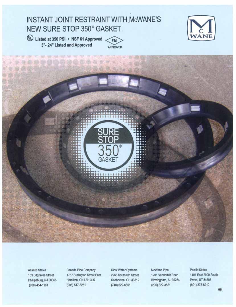
101 101
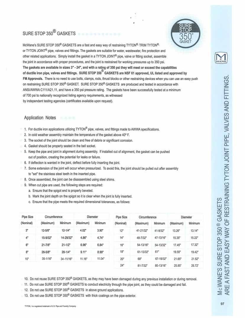
102 102
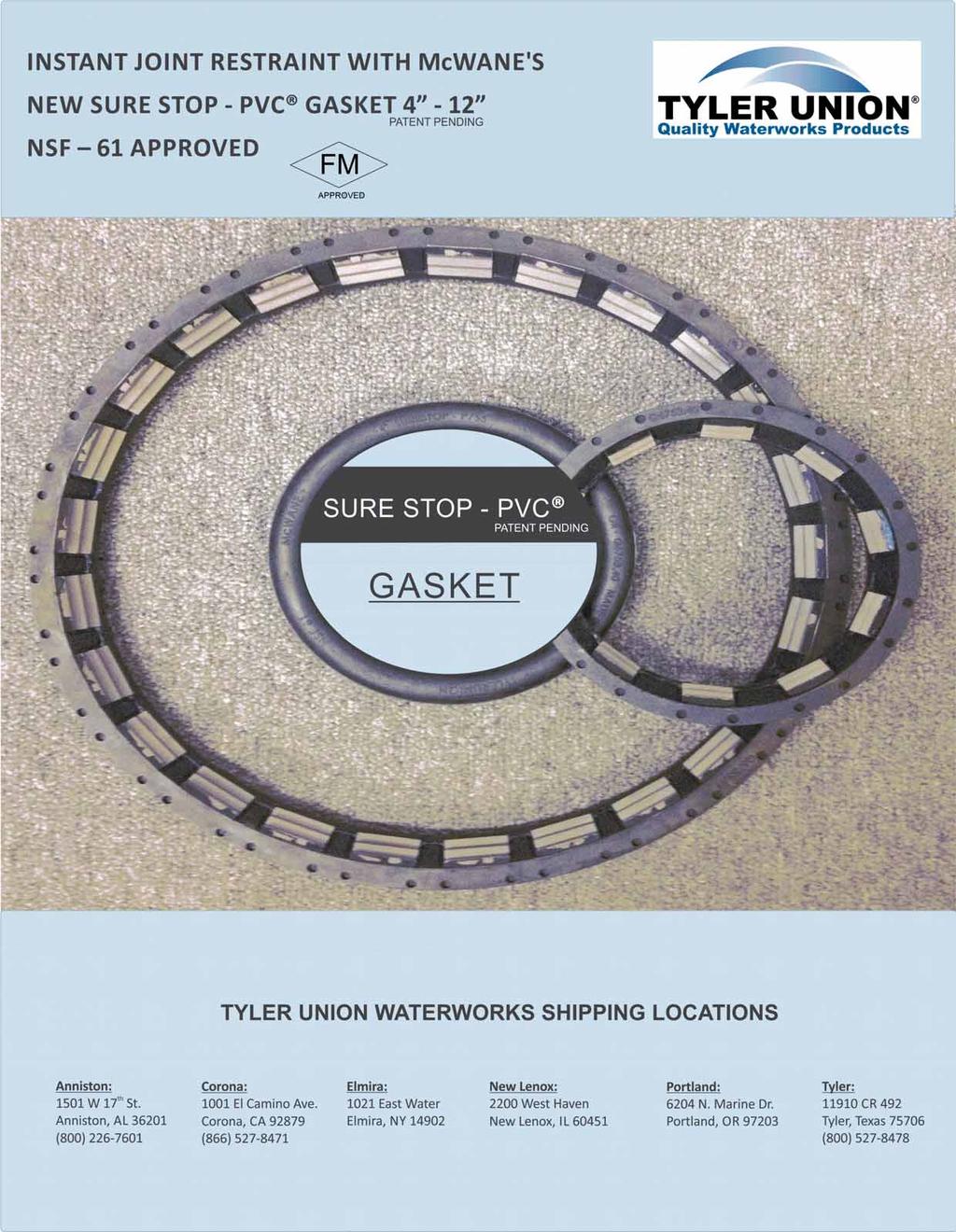
103 103

104 104
Utilities Catalog. PC-U2008, February, 2008
 Utilities Catalog PC-U2008, February, 2008 Tyler Utilities 11910 CR. 492 Tyler, Texas 75706 (800) 527-8478 Union Foundry Company Box 309 Anniston, Alabama 3602 (800) 226-7601 TABLE OF CONTENTS Item Page
TYLER UNION. Quality Waterworks Products. PC-2017, March, REGISTERED FIRMISO 9001:2015. Tyler Union
 TYLER UNION Quality Waterworks Products WATERWORKS CATALOG PC-2017, March, 2017 www.tylerunion.com 10014257 U L REGISTERED FIRMISO 9001:2015 CERTIFIED Tyler Union 11910 CR 492 TYLER, TEXAS 75706 (800)
UNION-TITE DUCTILE IRON C153 COMPACT FITTINGS
 Sizes 4"-12" UL Listed for Fire Main Equipment SAMPLE SPECIFICATIONS (Current ANSI/AWWA revisions apply) 4" through 24" Push-On joint ductile iron fittings shall be produced in accordance with all applicable
Water, Sewer & Drain Fittings
 Why Compact? Compact Joint are manufactured from a high strength, impact resistant ductile iron that offers a great margin of safety against service failures and provides vastly increased resistance to
TYLER UNION IMPORT RESTRAINTS LP NR
 SERIES 1000 MJ TUFGRIP WEDGE TYPE RESTRAINT FOR DUCTILE IRON PIPE MJ TUFGRIP for DI Pipe - GLAND ONLY N70-5760 MJ TUFGRIP for DI Pipe - W/ ACCESSORIES N71-6795 3 113805 $42.94 7 150 3 114352 $65.05 10
Price List Import Restraints
 LP2016-NR Effective: February 1, 2016 Supersedes All Previous Pricing Import Restraints For Other Products See: LP2015-ND - Import Utility Fittings, Glands, Accessory Packs LP2015-D - Domestic Utility
SECTION 5 AMERICAN. Ductile Iron Mechanical Joint Fittings
 ECION 5 AMERICAN Ductile Iron Mechanical Joint Fittings he principal standards covering full body mechanical joint fittings are ANI/AWWA C110/A21.10 and ANI/AWWA C111/A21.11. Compact ductile iron fittings
INFACT CORPORATION WATERWORKS PRODUCTS FLEX ADAPTOR SPECIFICATION S TOLL FREE:
 INFACT CORPORATION WATERWORKS PRODUCTS SPECIFICATION S TOLL FREE: 888-773-9130 email: info@infactcorp.com www.infactcorp.com ENGINEERING DATA / PRODUCT CHECKLIST EASY-TO-INSTALL SPACE-SAVING RESTRAINT
Section 8 AMERICAN. Flanged Pipe
 Section 8 AMERICAN Flanged Pipe The principal standards covering Flanged Pipe are ANSI/AWWA C115/A21.15 and ANSI/AWWA C110/A21.10. These and other standards are referenced throughout this Section either
C909 PVC Pipe Patent Pending
 1113 - H Copyright 2011 EBAA Iron, Inc. All Rights Reserved 19MJ00 Mechanical Joint Restraint for 4 through 12 inch C909 PVC Restraints for C909 PVC Pipe Patent Pending Features and Applications: For use
Ford Service Saddles and Tapping Sleeves
 DQS Inc. Section AA 09/2017 THE FORD METER BOX COMPANY, INC. CERTIFIED TO ISO 9001:2015 10004466 Ford Service Saddles and Tapping Sleeves Contents Recommended Product Application *Steel *C900/909*** Cast
ROMAC INDUSTRIES, INC. WIDE RANGE RESTRAINT. RESTRAINED END CAP page 6-7 NOW AVAILABLE FOR HDPE PIPE NO STIFFENER REQUIRED
 ROMAC INDUSTRIES, INC. WIDE RANGE RESTRAINT RESTRAINED COUPLING page 4-5 RESTRAINED END CAP page 6-7 RESTRAINED FLANGED COUPLING coming soon JUNE 2014 UPDATE NOW AVAILABLE FOR HDPE PIPE NO STIFFENER REQUIRED
Ford Fabricated Steel Products
 Ford Fabricated Steel Products Section N2 12/2000 The Ford Meter Box Co., Inc. 775 Manchester Avenue, P.O. Box 443, Wabash, Indiana, USA 46992-0443 Telephone: 219/563-3171 FAX: 1-800-826-3487 Overseas
Price List. Customer Service Support
 LP2019-BNG Effective: Supersedes All Previous Pricing Price List Bolts, Nuts, Gaskets & Accessory Packs (Less Glands) For Other Products See Latest Versions of: ND - Import Utility Fittings, Glands, Accessory
RESTRAINED JOINT HP LOK 30" 64" RESTRAINED JOINT NSF WATER & WASTEWATER. Certified to ANSI/NSF 61
 2 0 1 6 30" 64" E D I T I O N NSF WATER & WASTEWATER NSF P 2 Table of Contents Restrained Joint Pipe and Fittings 30" 64" 3 Suggested Specifications for Restrained Push-On Joint Pipe and Fittings 4 Joint
UNITED BRAND FITTINGS
 NFF0711 UNITED DUCTILE IRON CLASS 0 FLANGED FITTINGS UNITED BRAND FITTINGS AWWA C1, ANSI A21. Our dedication to the mechanical piping industry has given us the opportunity to provide you with a quality
StarFlex series 5000 Double-Ball Flexible Expansion Joint for the Protection of Water Wastewater, and Industrial Pipelines
 Joint Restraint Products StarFlex series 5000 Double-Ball Flexible Expansion Joint for the Protection of Water Wastewater, and Industrial Pipelines INFORMATION StarFlex Flexible Expansion Joints can deflect
PIPE OUTSIDE DIAMETER GUIDE
 June 7, 2018-1 PIPE OUTSIDE DIAMETER GUIDE PIPE OUTSIDE DIAMETER GUIDE - SMALL DIAMETER PIPE SIZES NOMINAL PIPE SIZES 1 /2" 3 /4" 1" 1 1 /4" 1 1 /2" 2" 2 1 /2" THIS O.D. GUIDE IS FOR YOUR CONVENIENCE &
PVC Stargrip series 4000 Mechanical Joint Wedge Action Restraint for Plastic Pressure Pipe
 PVC Stargrip series 4000 Mechanical Joint Wedge Action Restraint for Plastic Pressure Pipe INFORMATION The PVC Stargrip Mechanical Joint Restraint System is an exceptional restraint system for mechanical
Ford Bolted Flex Couplings. Section M. 5/2008; Web Revision 10/2010
 Section M 5/2008; Web Revision 10/2010 Ford Bolted Flex Couplings The Ford Meter Box Company, Inc. 775 Manchester Avenue, P.O. Box 443, Wabash, Indiana, USA 46992-0443 Telephone: 260-563-3171 FAX: 800-826-3487
Super Flange series 7200 Designed for use on Ductile Iron, Steel, PVC, PVCO and HDPE Pipes
 Designed for use on Ductile Iron, Steel, PVC, PVCO and HDPE Pipes INFORMATION The Series 7200 Super Flange is a restrained flange adapter designed to connect plain end pipe to a flange end component. May
PVC Stargrip series 4000 Mechanical Joint Wedge Action Restraint for Plastic Pressure Pipe
 Joint Restraint Products PVC Stargrip series 4000 Mechanical Joint Wedge Action Restraint for Plastic Pressure Pipe INFORMATION The PVC Stargrip Mechanical Joint Restraint System is a unique product with
TOTAL PIPING SOLUTIONS, INC. TRIPLE-TAP
 TOTAL PIPING SOLUTIONS, INC. TRIPLE-TAP Extended Range Stainless Steel Push Plug Line Stop Tapping Sleeve Technical Specifications Controlled Document: ENGTS-05/120417 December 2017 TRIPLE TAP Extended
Ford Service Saddles and Tapping Sleeves
 Section AA 04/2013; web revision 02/2014 Ford Service Saddles and Tapping Sleeves The Ford Meter Box Company, Inc. 775 Manchester Avenue, P.O. Box 443, Wabash, Indiana, USA 46992-0443 Telephone: 260-563-3171
2009 Edition. Tyton fittings 14"-24" NSF. For Water & Wastewater, Fire Protection & Industrial Applications. Certified to ANSI/NSF 61
 14"-24" Tyton fittings For Water & Wastewater, Fire rotection & Industrial Applications 2 Table of Contents TYTON Fittings 3 Assembly of TYTON Fittings 4 Bell Dimensions 6 Thickness and Dimensions 90 Bends
San Antonio Water System Standard Specifications for Construction ITEM NO. 836 GREY-IRON AND DUCTILE-IRON FITTINGS
 ITEM NO. 836 GREY-IRON AND DUCTILE-IRON FITTINGS 836.1 DESCRIPTION: This item shall consist of grey-iron and ductile-iron fittings installation and adjustment installed in accordance with these specifications
IROn PIPe. McWane DUcTILe
 McWane DUcTILe IROn PIPe nsf 61 ISO 9001 DIPRa Boltless restrained joint systems Multiple design options available from 3 36 Fast and easy installation 350 pressure rating Independently tested www.mcwane.com
Section N. 09/2017 Web Revision 10/23/2017 THE FORD METER BOX COMPANY, INC. CERTIFIED TO ISO 9001: Ford Fabricated Steel Products
 DQS Inc. THE FORD METER BOX COMPANY, INC. CERTIFIED TO ISO 9001:2015 10004466 Section N 09/2017 Web Revision 10/23/2017 Ford Fabricated Steel Products Contents Page Product Numbering System... 3 Information...............................................................
Smith-Blair OMNI Coupling System Advantages:
 OMNI Coupling System SmithBlair s OMNI Coupling System utilizes the tremendous tensile strength of ductile iron to your best advantage. Applying the principles of space age technology to engineer the OMNI
HP250II AND HP250 BUTTERFLY VALVES Engineering Creative Solutions for Fluid Systems Since 1901
 H250II AND H250 BUTTERFLY VALVES Engineering Creative Solutions for Fluid Systems Since 1901 TABLE OF CONTENTS RATT H250II Scope of Line... 1 Design and Construction Details... 1 ipe Mating Chart... 1
C110 DUCTILE IRON FLANGED FITTINGS
 C110 DUCTILE IRON FLANGED FITTINGS SIZES: 2-64 C110 DUCTILE IRON FLANGED FITTINGS BASIC SPECIFICATIONS MATERIAL: Ductile Iron ASTM A536 Grade 60-42-10, 65-45-12 or 70-50-05. PRESSURE: 250 PSI Water Working
Rated to the New, Higher Pressure Classes in Latest Editions of AWWA C900 and C909. Joint Restraint Products
 Pipe Restrainers series 1000G2 1000G2C Restrainers for AWWA CI OD C900/C909 PVC/PVCO Pipe with MJ or Ductile Iron Push-On Fittings (Formerly Series 9000) INFORMATION Second Generation (Gen 2) PVC Restrainers
Steel Fabricated Coupling
 Steel Fabricated Coupling Straight Connection IMPORTANT LINKS Click appropriate words to go to: Standard Limited Warranty Sales Terms & Conditions Freight Policy Returns Policy Corrosion & Product Selection
Ford Brass Saddles Style 101B and 202B
 101B Ford Brass Saddles 101B and 202B 101B, 3/4" and 1" Taps 202B, 3/4" through 2" Taps Specifications Body - 85-5-5-5 brass alloy as per ASTM B62, ASTM B584 and AW WA C800. Threads may be FIP, AW WA,
866.DIP.PIPE P 1 NSF Edition. Certified to ANSI/NSF Edition 4" 36" REVISED 11.09
 P 1 4" 36" For FIRE PROTECTION, Water & Wastewater P 2 Table of Contents TR FLEX Restrained Joint Pipe and Fittings 4"-36" 3 Suggested Specification Wording For 4"-36" Restrained Push-on Joint Pipe and
Section 2. Shurjoint Grooved Fittings Flow Data / Friction Resistance Ductile Iron Grooved Fittings. Wrought Grooved Fittings
 Section 2 Cast & Wrought Grooved Fittings Shurjoint Grooved Fittings... 56 Flow Data / Friction Resistance... 56 Ductile Iron Grooved Fittings 7110 / 7111 / 7112 / 7113 Elbows... 57 7120 / 7135 / 7130
Water Distribution Solutions
 Water Distribution Solutions Table of Contents WaterMaster 5CD250 Fire Hydrants 6 WaterMaster 5BR250 Fire Hydrants 8 FlowMaster Resilient Wedge Gate Valves 11 Valve Boxes 17 Meter Boxes 22 Table of Contents
P EDITION 4" 36" FOR FIRE PROTECTION, WATER & WASTEWATER REVISED 07.14
 P 1 2014 EDITION 4" 36" FOR FIRE PROTECTION, WATER & WASTEWATER P 2 Table of Contents TR FLEX Restrained Joint Pipe and Fittings 4"-36" 3 Suggested Specification Wording For 4"-36" Restrained Push-on Joint
HP LOK Pipe & Fittings DUCTILE IRON
 HP LOK Pipe & Fittings DUCTILE IRON PIPE FABRICATION RESTRAINED JOINTS FITTINGS GASKETS COATINGS & LININGS CONTENTS GENERAL INFO Pipe and Fittings 30" 64" 2 Suggested Specifications 3 ASSEMBLY INSTRUCTIONS
Precision is Central.
 Precision is Central. As experts in pipe joining solutions, we know precision is vital to every fitting and how they are fused. We offer the most complete range of conventional fusion fittings, injection
Water Distribution Solutions
 Water Distribution Solutions Table of Contents WaterMaster 5CD250 Fire Hydrants 6 WaterMaster 5BR250 Fire Hydrants 8 FlowMaster Resilient Wedge Gate Valves 11 Valve Boxes 17 Meter Boxes 22 Table of Contents
San Antonio Water System Standard Specifications for Construction ITEM NO. 836 GREY-IRON AND DUCTILE-IRON FITTINGS
 ITEM NO. 836 GREY-IRON AND DUCTILE-IRON FITTINGS 836.1 DESCRIPTION: This item shall consist of grey-iron and ductile-iron fittings installation and adjustment installed in accordance with these specifications
According to AWWA-standard
 According to -standard Water Fire fighting - UL/FM 304 Gate valves - Cast iron 320 Gate valves OS&Y 306 Service connection valves 322 Post indicators 306 Combi valves 307 Gate valves - 310 Gate valves
TR Flex Pipe & Fittings DUCTILE IRON
 TR Flex Pipe & Fittings DUCTILE IRON PIPE FABRICATION RESTRAINED JOINTS FITTINGS GASKETS COATINGS & LININGS CONTENTS GENERAL INFO Pipe 4" 36" 2 Suggested Specification Wording 3 ASSEMBLY INSTRUCTIONS Pipe
516509_tabs 11/16/10 4:55 AM Page 1 FIRE HYDRANTS
 Date Printed: November 2010 FIRE HYDRANTS or Tyton (6"),6, or 8" A EDDY FIRE HYDRANTS PARTS LIST WORKING PRESSURE: 150 PSI Note: Discontinued For Reference Only 350 PSI Working Pressure
MEDALLION HYDRANT. clowvalve.com AWWA C502 UL LISTED FM APPROVED NSF 61/372 CERTIFIED 250 PSI WORKING PRESSURE 10-YEAR LIMITED WARRANTY
 clowvalve.com MEDALLION HYDRANT AWWA C50 UL LISTED FM APPROVED NSF 6/37 CERTIFIED 50 PSI WORKING PRESSURE 0-YEAR LIMITED WARRANTY Clow Valve, A Division of McWane, Inc. MEDALLION HYDRANT FIRE PROTECTION
F L A C110 FLANGED FITTINGS CAST IRON & DUCTILE IRON 2007 Sigma Corporation, All Rights Reserved
 F L A C110 & N GE D 2-54 / BASIC SPECIFICATIONS www.sigmaco.com / MATERIAL: Cast Iron: ASTM A48, Grade 25B (2-14 ) / Grade 30B (16-54 ) Ductile Iron ASTM A536 PRESSURE: 250 PSI Water Working Pressure for
MACRO HP. NEW SMALLER SIZES Macro HP is Now Available for 2-12 inch Pipe Sizes. patent number:
 ACROMACROMACROMA MACRO HP ROMAC S SECOND GENERATION TWO-BOLT E X T E N D E D R A N G E C O U P L I N G NEW SMALLER SIZES Macro HP is Now Available for 2-12 inch Pipe Sizes patent number: 8448993 BMACROHP
VALVES, FIRE HYDRANTS, AND APPURTENANCES
 VALVES, FIRE HYDRANTS, AND APPURTENANCES PART 1 - GENERAL 1.01 SECTION INCLUDES A. Butterfly Valves B. Gate Valves C. Tapping Valve Assemblies D. Fire Hydrant Assemblies E. Flushing Devices (Blowoffs)
HANGERS, STRUT, AND FITTINGS SUBMITTAL
 HANGERS, STRUT, AND FITTINGS SUBMITTAL Prepared By: Submitted by: Enter Company Name INTERNATIONAL SEISMIC APPLICATION TECHNOLOGY A Division of Tomarco Contractor Specialties Enter Project Name 4848 Northam
FABRICATION TR Flex Pipe & Fittings DUCTILE IRON
 PIPE FABRICATION TR Flex Pipe & Fittings DUCTILE IRON RESTRAINED JOINTS FITTINGS GASKETS COATINGS & LININGS CONTENTS GENERAL INFO Pipe 4" 36" 2 Suggested Specification Wording 3 ASSEMBLY INSTRUCTIONS Pipe
SWING CHECK VALVES SERIES 52-SC SERIES 600
 SWING CHECK VALVES SERIES 52-SC SERIES 600 FEATURES/BENEFITS/SPECIFICATIONS AMERICAN Flow Control Series 52-SC Swing Check Valves incorporate design features to help increase service life for water and
SECTIO N 15 Phone: (866) Fax: (888)
 Fax: (888)") PVC FITTINGS SCHEDULE 40, 80, INSERT NYLON FITTINGS PVC & CPVC NIPPLES SECTIO N 15 www.cbsupplies.ca Phone: (866) 503-5523 Fax: (888) 562-2095 AGI@cbsupplies.ca PRODUCTS LIST SCHEDULE 40 PVC PRESSURE FITTINGS
PVC FITTINGS SCHEDULE 40, 80, INSERT NYLON FITTINGS PVC & CPVC NIPPLES SECTIO N 15 www.cbsupplies.ca Phone: (866) 503-5523 Fax: (888) 562-2095 AGI@cbsupplies.ca PRODUCTS LIST SCHEDULE 40 PVC PRESSURE FITTINGS
UNITED BRAND FITTINGS
 FLANGE DETAILS Class 5 S ize O.D. B.C. T Bolt Hole Bolt Dia. & of Dia. Length Bolts 4.75 5/ 8 4 x 4 50 4 x 4 3 4 4 x 4 4 00 5/ 4 x 3 8 5.00 50 5/ 7/ 8 4 x 3 8 6.00 50 7/ 8 4 x 3 8 8 3.50.75 8 7/ 8 4 x
Pipe Repair Products. A complete selection for all types of pipe
 Pipe Repair Products A complete selection for all types of pipe Mueller Service Saddles Manufactured and tested in accordance with ANSI/AWWA C800 & NSF 61 certified. Mueller service saddles, available
Heavy welded steel outlet half. 3/4-inch NPT test plug. Benefits
 622 Tapping Sleeve Recessed cavity for mating to lip on standard tapping valves per MSS SP60. Heavy welded steel outlet half. 3/4-inch NPT test plug. Roll resistant, self-energizing concave wedge gasket.
Pipe hanger solutions
 Product catalog Middle East offering Pipe hanger solutions for commercial and industrial applications B00 series B00 - Standard clevis hanger Pipe will not pinch when installing. 5 swing in either direction
INFACT CORPORATION WATERWORKS PRODUCTS FOSTER ADAPTOR SPECIFICATION S TOLL FREE:
 INFAC CORPORAION WAERWORKS PRODUCS FOSER ADAPOR SPECIFICAION S O FREE: 888-773-9130 email: info@infactcorp.com www.infactcorp.com ENGINEERING DAA / PRODUC OVERVIEW FOSER ADAPOR BO-HRU MECHANICA JOIN RESRAIN
FIRE PROTECTION PRODUCTS
 SUPER CENTURION FIRE HYDRANT Mueller Super Centurion Fire Hydrant Since its introduction in 1976, millions of Centurion fire hydrants have been installed throughout North America. There are a number of
JCM 101 Universal Clamp Couplings
 JCM 1 Universal Clamp Couplings JCM 1 Universal Clamp Coupling - Single Band JCM Universal Clamp Couplings provide a full circumferential seal and wide range for the permanent repair or reconnection of
FACILITY WATER DISTRIBUTION PIPING
 SECTION 221113 - FACILITY WATER DISTRIBUTION PIPING PART 1 - GENERAL 1.1 RELATED DOCUMENTS A. Drawings and general provisions of the Contract, including General and Supplementary Conditions and Division
FITTINGS AND FABRICATIONS DESIGNED AND ENGINEERED HIGH DENSITY POLYETHYLENE PIPE
 Effective May 24, 2002 Cancels all previous publications U.S. Price $12.95 FITTINGS AND FABRICATIONS DESIGNED AND ENGINEERED FOR HIGH DENSITY POLYETHYLENE PIPE JCM Industries, Inc. P.O. Box 1220 Nash,
Cam-Lock 111, 120 Joint Restraints Patent Pending
 111, 120 Joint Restraints The Next Generation Joint Restraint Technology Smith-Blair Cam-Lock joint restraint products provide a fast and economical means restraining mechanical joint water and wastewater
Series 1500TD Bell Restraint Harness for Ductile Iron & C900 PVC Pipe Split Serrated Restraint Rings on Both Sides of the Bell
 Series 00TD Bell Restraint Harness for Ductile Iron & C900 PVC Pipe Split Serrated Restraint Rings on Both Sides of the Bell Features and Applications: Restraint for Ductile Iron Pipe at Push- On Bells,
TAPPING & SERVICE SADDLES
 TAPPING & SERVICE SADDLES The Standard of Excellence in the Industry CS12 CSC1 CS22 CSC2 CNS1 CDS1 CNS2 CDS2 CFS CFT-TO 1213 BADGER STREET YORKVILLE, ILLINOIS 60560 (630) 553-0840 (800) 426-4301 FAX (630)
UNITED BRAND FITTINGS
 UNITED BRAND FITTINGS ANSI B. Class 5 ( ~ ) AWWA C Class 0 (3 ~ ) Our dedication to the mechanical piping industry has given us the opportunity to provide you with a quality comprehensive line of flanged
SUB WATER DEPARTMENT STANDARD CONSTRUCTION SPECIFICATIONS TABLE OF CONTENTS SECTION WATER DISTRIBUTION VALVES
 SUB WATER DEPARTMENT STANDARD CONSTRUCTION SPECIFICATIONS TABLE OF CONTENTS SECTION 33 12 16 WATER DISTRIBUTION VALVES PART 1 GENERAL... 2 1.1 Description... 2 1.2 Reference Specifications, Codes, and
FABRICATION TR Flex Pipe & Fittings DUCTILE IRON
 PIPE FABRICATION TR Flex Pipe & Fittings DUCTILE IRON RESTRAINED JOINTS FITTINGS GASKETS COATINGS & LININGS CONTENTS GENERAL INFO Pipe " " Suggested Specification Wording ASSEMBLY INSTRUCTIONS Pipe & Fittings
Ductile and Cast Iron Flanged Fittings Metalfit
 Ductile and Cast Iron Flanged Fittings 2 48 Metalfit Flanged oint Dimensions NSI/WW C110/21.10 BC OD Size OD BC ole Dia. Bolt Size No. Bolts 2 6.00 4.75 0.62 0.75 5/8 x 2-1/4 4 2-1/2 7.00 5.50 0.69 0.75
Section M. 04/2014 Web Revision 10/02/2015. Ford Bolted Flex Couplings
 THE FORD METER BOX COMPANY, INC. ISO 9001:2008 10002505 Section M 04/2014 Web Revision 10/02/2015 Ford Bolted Flex Couplings Contents Coupling Numbering System... 3 Features of Ford Cast Couplings, Style
Harlingen Water Works System Approved Products List For Subdivisions. January 11, 2005
 Harlingen Water Works System Approved Products List For Subdivisions January 11, 2005 Revised March 24, 2016 Harlingen Water Works System Approved Products List for Subdivisions Table of Contents: 1. Valves
INSERTA VALVE SLEEVE INSERTA VALVE ASSEMBLY. Valve insertion, simplified MATERIAL SPECIFICATIONS MATERIAL SPECIFICATIONS.
 MADE IN U.S.A. Valve insertion, simplified 10-12 installations in cast iron, ductile iron, A/C, PVC C-900 and steel pipe No Loss of Pressure Minimal Water Loss Completion time is less than 2 hours Much
CLOW CANADA - M-67 HERITAGE BRIGADIER FIRE HYDRANT SPECIFICATION
 CLOW CANADA - M-67 HERITAGE BRIGADIER FIRE HYDRANT SPECIFICATION TESTING AND DESIGN SPECIFICATIONS (PER AWWA C502 / NSF /ULC & FM) 1. Hydrant shall be manufactured in accordance with AWWA C502 latest revision
AMERICAN FLOW CONTROL 4 3/4 WATEROUS TREND FIRE HYDRANT
 AMERICAN FLOW CONTROL 4 3/4 WATEROUS TREND FIRE HYDRANT CONSTRUCTION Fully complies with ANSI/AWWA C502 and is available UL Listed and Approved by FM Approvals in applicable configurations. DUCTILE IRON
THOMAS. Unifit Premier Series. Couplings & Flange Adaptors Non Restrained Products PIPE PRODUCTS
 THOMAS Couplings & Flange Adaptors Non Restrained Products PIPE PRODUCTS Unifit Premier Series Universal Pipe Couplings and Flange Adaptors for all Rigid Pipe J1 Unifit Premier Series Application Locally
visit us online at
 PRICE SHEET (PL-1014-VLV Replaces PL-0513-VLV) TABLE OF CONTENTS VALVES & HYDRANTS Page(s) Product Line Price Sheet 1 AWWA C515 Gate Valves NRS Series 2010 & 1010 PL-1014 Multiplier 2 AWWA C515 Gate Valves
The Number One Choice of Line Stopping Contractors
 JCM 0 Line Stop Fittings Take a Look!!! JCM 0 FAMILY OF LINE STOP FITTINGS HAS EPANDED New Plug Option - New Numbering System Whatever your application needs, JCM has it! JCM Industries offers the largest
ADMIRAL HYDRANT. clowvalve.com
 clowvalve.com ADMIRAL HYDRANT AWWA C502 UL LISTED FM APPROVED NSF 61/372 CERTIFIED 250 PSI WORKING PRESSURE 350 PSI WORKING PRESSURE AVAILABLE 10-YEAR LIMITED WARRANTY Clow Valve, A Division of McWane,
3"-42" FLANGE-TYTE II TM FULL FACE GASKET FOR FLANGED JOINTS 2016 EDITION FOR WATER & WASTEWATER, FIRE PROTECTION & INDUSTRIAL APPLICATIONS
 TM FOR FLANGED JOINTS 3"-42" Certified to ANSI/NSF 61 FOR WATER & WASTEWATER, FIRE PROTECTION & INDUSTRIAL APPLICATIONS Table of Contents FULL FACE TM Gasket Introduction 3 Pressure Performance 3 Torque
Section M. 06/2017 Web Revision 12/15/2017 THE FORD METER BOX COMPANY, INC. CERTIFIED TO ISO 9001: Ford Cast Couplings and Adapters
 DQS Inc. THE FORD METER BOX COMPANY, INC. CERTIFIED TO ISO 9001:2015 10004466 Section M 06/2017 Web Revision 12/15/2017 Ford Cast Couplings and Adapters Contents Page Coupling Numbering System.... 3 Features
' ' ' ' LISTED Elbows Tees Crosses Wyes Reducers Flanges Converters Gaskets Nuts&Bolts
 .., I.,.,... I I...... I I ',,,, ", Elbows Tees Crosses Wyes Reducers Flanges Converters Gaskets Nuts&Bolts ' ; i ',,.) I ' ' ' ' AWWA C Class 50 (3"' ANSI B. Class 5 ("' ANSI B. Class 50 (3"' c@us LISTED
Hole-cutting. cutting a hole. After the hole has been cut all rough edges must be removed and the area within 5/8 (16mm) of the hole
 of the hole") Mechanical Tees Hole-cutting Shurjoint mechanical tees provide a fast and easy mid-point branch outlet, eliminating the need for welding or the use of multiple fittings. The Model M21 features a female
Mechanical Tees Hole-cutting Shurjoint mechanical tees provide a fast and easy mid-point branch outlet, eliminating the need for welding or the use of multiple fittings. The Model M21 features a female
Reference Data. Schedule 40 Steel Pipe Data. Schedule 80 Steel Pipe Data
 Schedule 40 Steel Pipe Data Maximum Recommended Pipe Size Pipe O.D. Thickness Weight of Pipe Filled With Water Span* Hanger Rod Ft. Meter Sizes 3/8" (10).675 (17.1).091 (2.3).6 (.9).7 (1.0) 7 (2.13) 3/8"-16
JEFFERSON UTILITIES 270 INDUSTRIAL BLVD. KEARNEYSVILLE, WV (304) STANDARDS AND SPECIFICATIONS
 STANDARDS AND SPECIFICATIONS") JEFFERSON UTILITIES 270 INDUSTRIAL BLVD. KEARNEYSVILLE, WV 25430 (304) 728-2077 STANDARDS AND SPECIFICATIONS FEBRUARY 28, 2018 1 TABLE OF CONTENTS GENERAL MATERIAL... 3 WATER... 5 DUCTILE IRON PIPE...
JEFFERSON UTILITIES 270 INDUSTRIAL BLVD. KEARNEYSVILLE, WV 25430 (304) 728-2077 STANDARDS AND SPECIFICATIONS FEBRUARY 28, 2018 1 TABLE OF CONTENTS GENERAL MATERIAL... 3 WATER... 5 DUCTILE IRON PIPE...
InsertaValve Sleeve. InsertaValve Valve Assembly. Valve Insertion, simplified. Material Specifications. Transmate InsertaValve
 Material Specifications Material Specifications Sleeve 10" - 12" installations in cast iron, ductile iron, A/C, PVC C-900 and steel pipe No Loss of Pressure Minimal Water Loss Completion time is less than
Mueller Super Centurion 250 Fire Hydrant
 Mueller Super Centurion 250 Fire Hydrant Designed for efficient flow and outstanding, long-term reliability Mueller Super Centurion 250 Fire Hydrant...250 psig rating, high flow, dependable performance,
K81-D FIRE HYDRANT GUARDIAN AWWA C502 NSF YEARS. For Generations CERTIFICATIONS ISO 9001 ISO BS OHSAS
 GUARDIAN K81-D FIRE HYDRANT CERTIFICATIONS ISO 9001 ISO 14001 BS OHSAS 18001 AWWA C502 NSF 61 140 YEARS WWW.KENNEDYVALVE.COM C For Generations COMPONENTS AND FEATURES A B C E D F G H J L M K N P Q S R
 GENERAL FEATURES / SPEC M&H AWWA C502 FIRE HYDRANTS Style 929 Traffic Model 250 PSI Working Pressure 500 PSI Hydrostatic Test AWWA UL / FM Approval Type: Compression type, opening against line pressure.
Series 800 AWWA Butterfly Valves
 Series 800 AWWA Butterfly Valves Valve and Gate Group A Century of Experience GA valves are known for long term reliability in the most demanding water and wastewater applications. Whether a simple check
ALPHA Wide Range Restrained Joint
 ROMAC INDUSTRIES, INC. 1-800-426-9341 www.romac.com MADE IN U.S.A. January 8, 2015 ALPHA Wide Range Restrained Joint WIDE RANGE RESTRAINED JOINT Wide covers DI through IPS PVC pipe diameters without having
Pipe Size Pipe OD TwinSeal Hinged Design for IPS PVC Pipe MODEL 3402 BRONZE SADDLE FOR COPPER TUBING
 MULTIPLIER SERVICE SADDLES MODEL 3401 BRONZE SADDLE FOR IPS PVC BODY CASTINGS: Waterworks Bronze (85-5-5-5) per ASTM B584 and AWWA C800. FASTENERS: Silicon Bronze per ASTM B98. GASKET: Patented SBR TwinSeal
BUTTERFLY VALVES. An industry leader in underground and in-plant applications. STYLE STYLE Consult factory for sizes
 An industry leader in underground and in-plant applications. BUTTERFLY VALVES STYLE 4500 3 24 STYLE 1450 30 54 Consult factory for sizes 60 120 C504 Class 150B & 250B M&H Valve is a division of McWane,
Joint Restraint System
 Joint Restraint System For IPS, DPS & DIN Plastic Pipe 10-YEAR Warranty Parts & Labor ask for details PIPE TO FITTING LH-Series 2-12 IPS Pipe s LHD-Series 4-24 DPS Pipe s DLH-Series 63-400MM DIN Pipe s
San Antonio Water System Standard Specifications for Construction ITEM NO. 834 FIRE HYDRANTS
 San Antonio Water System Standard Specifications for Construction ITEM NO. 834 FIRE HYDRANTS 834.1 DESCRIPTION: This item shall consist of fire hydrant installations using joint restraints in accordance
PVC Gasketed Fittings for PVC IPS Pressure Pipe ENGINEERED FOR DURABILITY
 For the most up-to-date version of this price list, EFFECTIVE MARCH 4, 2019 ENGINEERED FOR DURABILITY HARRINGTON CORPORATION P.O. BOX 10335 LYNCHBURG, VIRGINIA 24506-0335 For the most up-to-date version
Series 77S-M1 ( 1 4" 3") Cast Iron Wye-pattern Strainers
 Cast Iron Wye-pattern Strainers") Series S-M1 ( 1 4" ") Cast Iron Wye-pattern Install strainers up stream of equipment that need protection from scale, rust, dirt, etc Pressure Rating: (non-shock) 250psi WSP (1.2 bar) @ 406 F (208 C),
Series S-M1 ( 1 4" ") Cast Iron Wye-pattern Install strainers up stream of equipment that need protection from scale, rust, dirt, etc Pressure Rating: (non-shock) 250psi WSP (1.2 bar) @ 406 F (208 C),
Style 234 Restrained Flexible Single-Gasket Coupling. System No. Submitted By Spec Sect Para Location Date Approved Date
 Victaulic Bolted Split-Sleeve Products (VBSP) Style 234 carbon steel couplings (formerly Depend-O-Lok Air/FluidMaster) are single-arch couplings that are commonly used in buried or exposed steel pipe applications
K81-DD FIRE HYDRANT GUARDIAN AWWA C502 NSF YEARS. For Generations CERTIFICATIONS ISO 9001 ISO BS OHSAS
 GUARDIAN K81-DD FIRE HYDRANT CERTIFICATIONS ISO 9001 ISO 14001 BS OHSAS 18001 AWWA C502 NSF 61 140 YEARS WWW.KENNEDYVALVE.COM C For Generations COMPONENTS AND FEATURES A B C E D F G H J K M L N P Q S R
Approved Branded Traceable Fire Protection & Waterworks Valves
 Approved Branded Traceable Fire Protection & Waterworks Valves (800) 766-0076 www.smithcooper.com Los Angeles, CA Atlanta, GA Vancouver, WA Chicago, IL AWWA C515 Compliant CONSIDER Your Options Tamper
APPROVED MATERIALS LIST SERVICE MATERIALS July 2017 **REVISED 12/6/17**
 APPROVED MATERIALS LIST SERVICE MATERIALS July 2017 **REVISED 12/6/17** SIZE DESCRIPTION MANUFACTURER & MODEL NUMBER CORPORATION STOPS 1" MIP x GRIP Comp ball corp stop Ford: FB 1100-4Q McDonald: 74704-BQ