Application List. Altronic EZRail Modular Ignition Rail System. Form EZRail AL 7-12
|
|
|
- Imogene Nash
- 6 years ago
- Views:
Transcription


1 pplication List ltronic EZRail Modular Ignition Rail System Form EZRail L 7-
2 GENERL INFORMTION ITEM DESCRIPTION PRT NO. EZ Rail ssembly ( or /bank) q = Ignition Type 5 or 7 = CPU-95; 6 or 8 = CPU-000 ab = No. Outputs 0 xy = Engine Mfr. See Listing z = Engine Series See Listing m = Engine Bank or B Bank, C = Rail w/o J-Box B Junction Box (/system) See Listing 593axx-xxx a = Ignition Type 4, 5 = CPU-95, DISN; 9 = CPU-000 Note: two options depending on the mounting location of the J-Box C Harness: Ignition to J-Box ( or ) L = 4, 36, 48, 60, 7, 96, 0, 44, L C Harness: J-Box to Rail ssembly (/bank) w/x90 and x80 connector L = 4, 36, 48, 60, 7, 96, 0, 44, 80 w/x90 connectors L = 4, 36, 48, 60, 7, 96, 0, 44, L 7930-L C3 Harness: Rail to Rail L = 4, 36, 48, 60, 7, 96 (inches) 7930-L Required only on integral engines E Shutdown Lead Cable (/system) w/80 connector L = 6 to 80 (inches) w/90 connector L = 6 to 80 (inches) w/x90 and x80 connector L =, 8, 4, 30, 36, 48, 60 (in.) *Use only with CPU-000 system with diagnostic module L L * F Coil Primary Cable ( or /cylinder) Unshielded Shielded (3-pin, 90 to 80 ) Shielded (3-pin, 80 to 80 ) Cut-to-length L =, 8, 4, 30, 36, 48, 60 (in.) L =, 8, 4, 30, 36, 48, 60, 7, 84, 96 (in.) KT L G Spark Plug Lead Cable (/coil, see catalog, Form I-C) Unshielded for Unshielded Coil Unshielded for Shielded Coil Flashguard Unshielded Leads 4" Ext. Flashguard Unshielded Leads 9" Ext. Safe-T-Leads Shielded Leads " Connection Shielded Leads " Connection L = 3, 7, 8,, 4 (inches) L =, 6, 8, (inches) L =, 6, 8, 0, 4 (inches) L = 7, 9, 33, 35 (inches) L = 4, 8, (inches) L = 0, 3, 6, 8, 4 (inches) L = 0, 3, 6, 8, 4 (inches) L L See form I-C See form I-C See form I-C L L H Coil Mounting ssembly ( or /bank) Optional 5805ab-xyz ab = No. Outputs xy = Engine Mfr. z = Engine Series 0- See Listing See Listing I Mounting Kit (see listing for qty.) Optional 5500-KT EZRail L 7- ll rights reserved LTRONIC, LLC 0
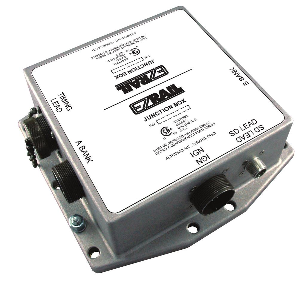
3 EZRIL SYSTEM COMPONENTS FOR HIGH SPEED ENGINE SHUTDOWN LED CBLE L L E C IGNITION TO J-BOX 7930-L B JUNCTION BOX 593axx-xxx J-BOX TO RIL 7930-L C 7930-L J-BOX TO RIL C 7930-L 7930-L NOTE: MOUNT EZRIL SSEMBLY FOR BOTH BNKS WITH 9-PIN CONNECTOR T THE PPROPRITE END OF THE ENGINE. H COIL MOUNTING SSEMBLY 5805ab-xyz EZRIL SSEMBLY EZRIL SSEMBLY F COIL PRIMRY CBLE KT COIL G SPRK PLUG SPRK PLUG LED CBLE EZRail L 7- ll rights reserved LTRONIC, LLC 0 3
4 LTRONIC EZRIL MODULR IGNITION RIL SYSTEM PPLICTION CHRT CPU-95/DISN ENGINE JX Item EZRail ssembly Part No. Item B J-Box at J-Box at end # end opposite of # Item C Item C Items F,G Item H Coil Mtg. Bar Part No. DPC-300, C None None DPC-540, C None None DPC C None None , C None None C None None C None None CTERPILLR C None None C None None B B B B Contact factory Contact factory G379 G B B Contact factory G CUMMINS G743, G C None None MEP MEP Contact factory MEP Contact factory MEP Contact factory MEP Contact factory SUPERIOR 6Gx85, 6GTLx Gx85, 8GTLx Gx85, GTLx G85, GT85 Endyn firing order B Item I Mtg. Kit EZRail L 7- ll rights reserved LTRONIC, LLC 0 4
5 LTRONIC EZRIL MODULR IGNITION RIL SYSTEM PPLICTION CHRT CPU-95/DISN ENGINE SUPERIOR (continued) Item EZRail ssembly Part No. Item B J-Box at J-Box at end # end opposite of # Item C Item C Items F,G Item H Coil Mtg. Bar Part No. 6G85, 6GTLx G85, 6GTLx Endyn firing order B GT GT85 Endyn firing order B WUKESH VGF B VHP VHP VHP6 ( rail/bank) VHP6 ( rails/bank) B S * T T * Requires qty. harnesses C3 see page. Item I Mtg. Kit 0 EZRail L 7- ll rights reserved LTRONIC, LLC 0 5
6 EZRIL SYSTEM COMPONENTS FOR INTEGRL ENGINE CPU-000 DIGNOSTIC MODULE CPU-000 OUTPUT MODULE C IGNITION TO J-BOX 7930-L SHUTDOWN LED CBLE Note: If Diagnostic Module is not used, use cable L or L E B JUNCTION BOX 593axx-xxx J-BOX TO RIL 7930-L C 7930-L J-BOX TO RIL C 7930-L 7930-L EZRIL SSEMBLY EZRIL SSEMBLY C3 RIL TO RIL 7930-L EZRIL SSEMBLY EZRIL SSEMBLY SPRK PLUG G COIL PRIMRY CBLE KT F SPRK PLUG LED CBLE H COIL MOUNTING SSEMBLY 5805ab-xyz F COIL PRIMRY CBLE KT EZRail L 7- ll rights reserved LTRONIC, LLC 0 6
7 LTRONIC EZRIL MODULR IGNITION RIL SYSTEM PPLICTION CHRT CPU-000 Note: engine firing order must be submitted with purchase order. ENGINE CLRK Item EZRail ssembly Part No. Item B J-Box at J-Box at end # end opposite of # Item C3 Harness Item H Coil Mtg. Bar Part No. HR Z HR Z HR Z TL Z TL-6/ Z TL-6/ Z TLC Z TL Z TLC Z TL-0/ Z TL-0/ Z TCV Z TCV Z TCV Z TCV Z COOPER-BESSEMER GMV-6 Series Z GMV-8 Series Z GMV-8 flat crank Z GMV-0 Series Z GMVH- flat crank Z GMW-6 Series Z GMW-8 Series Z GMW-0, GMWC-0 GMW Z Z GMW- Series Z V50, 6V75, 6W Z V50, 8V75, 8W Z V50,0V75,0W Z V50,V75,W Z V50,6V75,6W Z LS8G Z DE LVL HV Z HV Z HV Z Item I Mtg. Kit EZRail L 7- ll rights reserved LTRONIC, LLC 0 7

8 LTRONIC EZRIL MODULR IGNITION RIL SYSTEM PPLICTION CHRT CPU-000 Note: engine firing order must be submitted with purchase order. ENGINE INGERSOLL RND Item EZRail ssembly Part No. Item B J-Box at J-Box at end # end opposite of # Item C3 Harness Item H Coil Mtg. Bar Part No. 36KVG, 6KVG Z KVG, 83KVG Z KVGR Z KVG Z KVS, 36KVS, 36KVSR Z KVS, 48KVSR Z KVG, 40KVG Z KVG Z Item I Mtg. Kit 40/50 KVG/KVGR (-cyl. crank) Z /50 KVS/KVSR (-cyl. crank) Z /5 KVG/KVGR/KVS/KVSR Z KVT, 38KVR Z KVT, 40KVR Z KVT, 5KVR Z KVT, 66KVR Z EZRail L 7- ll rights reserved LTRONIC, LLC 0 8
APPLICATION LIST. ALTRONIC EZRAIL MODULAR IGNITION RAIL SYSTEM FORM EZRail AL 7-08 GENERAL INFORMATION
 www.altronicinc.com PPLICTION LIST GENERL INORMTION IT. DESCRIPTION PRT NO. LTRONIC EZRIL MODULR IGNITION RIL SYSTEM ORM EZRail L 7-08 EZ Rail ssembly ( or /bank) q = Ignition Type 5 or 7 = CPU-95; 6 or
Ignition Accessories
 Ignition Accessories Ignition Accessories CONTENTS Introduction... 3 Altronic EZRail Modular Ignition Rail System Features and Benefits... 4 System Components for High Speed Engines... 5 System Components
Ignition Accessories
 Ignition Accessories Ignition Accessories CONTENTS Introduction... 3 Altronic EZRail Modular Ignition Rail System Features and Benefits... 4 System Components for High Speed Engines... 5 System Components
APPLICATION LIST REQUIRED ITEMS: A: CPU-95 IGNITION MODULE, 1 PER SYSTEM. 1
 HOERBIGER Engine Solutions APPLICATION LIST CPU-95/CPU-95EVS DIGITAL IGNITION SYSTEMS MEDIUM ENGINES, 2 18 CYLINDERS FORM CPU-95/95EVS AL 9-14 REQUIRED ITEMS: A: CPU-95 IGNITION MODULE, 1 PER SYSTEM 791950-8
Ignition Systems for Industrial Engines
 Ignition Systems for Industrial Engines Altronic Ignition Systems CONTENTS Altronic Ignition Systems Overview and Guide Contents and Introduction... 2 Application Guide... 3 Solid-State/Mechanical Ignition
Crane Control Class 9055
 Catalog 17 CONTENTS Description.....................................................Page pplication Data................................................... General Information and Pricing.......................................
SAN JOAQUIN VALLEY UNIFIED AIR POLLUTION CONTROL DISTRICT. Appendix F: EPA TSD for NOx SIP Call August 18, 2011 APPENDIX F
 APPENDIX F EPA Stationary Reciprocating Internal Combustion Engines Technical Support Document For NOx SIP Call F - 1 This page intentionally blank. F - 2 Stationary Reciprocating Internal Combustion Engines
KENCO ENGINEERING COMPANY P.O. BOX TULSA, OK PHONE(918) FAX: (918)
 FAX: (918)") KENCO ENGINEERING COMPANY P.O. BOX 470426 TULSA, OK 74147-0426 PHONE(918) 663-4406 FAX: (918) 663-4480 www.kenco-eng.com e-mail:info@kenco-eng.com INSTALLATION INSTRUCTIONS FOR MODEL 512 OIL LEVEL CONTROLLERS
KENCO ENGINEERING COMPANY P.O. BOX 470426 TULSA, OK 74147-0426 PHONE(918) 663-4406 FAX: (918) 663-4480 www.kenco-eng.com e-mail:info@kenco-eng.com INSTALLATION INSTRUCTIONS FOR MODEL 512 OIL LEVEL CONTROLLERS
KENCO ENGINEERING COMPANY P.O. BOX TULSA, OK PHONE: (918) FAX: (918)
 FAX: (918)") KENCO ENGINEERING COMPANY P.O. BOX 470426 TULSA, OK 74147-0426 PHONE: (918) 663-4406 FAX: (918) 663-4480 www.kenco-eng.com e-mail: info@kenco-eng.com INSTALLATION INSTRUCTIONS FOR MODEL KLC OIL LEVEL CONTROLLERS
KENCO ENGINEERING COMPANY P.O. BOX 470426 TULSA, OK 74147-0426 PHONE: (918) 663-4406 FAX: (918) 663-4480 www.kenco-eng.com e-mail: info@kenco-eng.com INSTALLATION INSTRUCTIONS FOR MODEL KLC OIL LEVEL CONTROLLERS
CPU-XL VariSpark ADVANCED DIGITAL IGNITION SYSTEM FOR LARGE GAS ENGINES
 CPU-XL VariSpark ADVANCED DIGITAL IGNITION SYSTEM FOR LARGE GAS ENGINES n State-of-the-art, crankshaft-referenced digital ignition system for natural-gas fueled integral compressor engines n Innovative
KENCO ENGINEERING COMPANY P.O. BOX TULSA, OK PHONE(918) FAX: (918)
 FAX: (918)") KENCO ENGINEERING COMPANY P.O. BOX 470426 TULSA, OK 74147-0426 PHONE(918) 663-4406 FAX: (918) 663-4480 www.kenco-eng.com e-mail:info@kenco-eng.com INSTALLATION INSTRUCTIONS FOR MODEL KLCM OIL LEVEL CONTROLLERS
KENCO ENGINEERING COMPANY P.O. BOX 470426 TULSA, OK 74147-0426 PHONE(918) 663-4406 FAX: (918) 663-4480 www.kenco-eng.com e-mail:info@kenco-eng.com INSTALLATION INSTRUCTIONS FOR MODEL KLCM OIL LEVEL CONTROLLERS
KENCO ENGINEERING COMPANY P.O. BOX TULSA, OK PHONE(918) FAX: (918)
 FAX: (918)") KENCO ENGINEERING COMPANY P.O. BOX 470426 TULSA, OK 74147-0426 PHONE(918) 663-4406 FAX: (918) 663-4480 www.kenco-eng.com e-mail:info@kenco-eng.com INSTALLATION INSTRUCTIONS FOR MODEL KES OIL LEVEL SWITCHES
KENCO ENGINEERING COMPANY P.O. BOX 470426 TULSA, OK 74147-0426 PHONE(918) 663-4406 FAX: (918) 663-4480 www.kenco-eng.com e-mail:info@kenco-eng.com INSTALLATION INSTRUCTIONS FOR MODEL KES OIL LEVEL SWITCHES
IGNITION TOOLS & TEST EQUIPMENT
 PRODUCT GUIDE 07 REV. 06/2013 IGNITION TOOLS & TEST EQUIPMENT Chapter 07 07/1 IGNITION TOOLS & TEST EQUIPMENT SparkView MOTORTECH HIGH VOLTAGE INDICATOR The SparkView is a handheld device developed by
Chevrolet Avalanche, Silverado 1500, Suburban, Tahoe
 Engine Oil Consumption on Aluminum Block/Iron Block Engines with Active Fuel Management (AFM) (Install AFM Oil Deflector and Clean Carbon from Cylinder) 2007-2010 Cadillac Escalade, Escalade ESV, Escalade
INSTALLATION INSTRUCTIONS
 INSTALLATION INSTRUCTIONS WARNING: WARNING: www.altronicinc.com DEVIATION DEVIATION FROM THESE FROM INSTRUCTIONS THESE INSTRUCTIONS MAY LEAD MAY TO LEAD IMPROPER TO IMPROPER OP- ERATION OF ENGINE THE MACHINE
1500 SERIES LARGE CAPACITY ULTRA 2 LOW NO X
 1500 SERIES LRGE CPCITY ULTR 2 LOW NO X URNER CPILITIES High release rates with moderate air pressure Good turndown with flame characteristics and direction maintained Stable flames can range from highly
Operating Instructions
 Operating Instructions CPU-XL VariSpark Digital Ignition System with Enhanced Display Form 1.0 OVERVIEW 1.1 The Altronic CPU-XL VariSpark Digital Ignition with enhanced display is a DCpowered, microprocessor-based,
OIL LEVEL CONTROLLERS AND OIL LEVEL SWITCHES
 OIL LEVEL CONTROLLERS AND OIL LEVEL SWITCHES FEATURES: Reduces maintenance by maintaining a constant oil level Protects against lubrication failure Controller mechanism fully removable without draining
Integral Ignition Coils For Shielded Applications
 Integral Ignition Coils For Shielded Applications GAS ENGINE TECHNOLOGY reliable efficient worldwide Integral Ignition Coils Slim Design General Features Primary connector pole for ALTRONIC compatibility
Gen III HEMI Harness PN or
 Gen III HEMI Harness PN 558-106 or 558-107 This wiring harness interfaces a Holley EFI ECU to a Gen III HEMI engine. It is meant to be used in conjunction with an injector harness, a coil harness, and
Before performing spark test, ensure ignitor is properly grounded.
 Page 1 of 10 IGNITION CHECKS SPARK TEST NOTE: Before performing spark test, ensure ignitor is properly grounded. 1. Disconnect high tension coil wire from distributor. Hold coil wire approximately 1/2"
Carl M. Cummings Manufacturing Company. A Division of Maven Engineering Corporation
 Carl M. Cummings Manufacturing Company USA 15946 Derwood Road Rockville, Maryland USA 20855 Main Phone: 301-519-3400 Main Fax: 301-975-0712 sales@mavencorporation.com 2818-A Metropolitan Blvd. Pomona,
DTC P0325 KNOCK SENSOR 1 CIRCUIT (BANK 1 OR SINGLE SENSOR) DTC P0327 KNOCK SENSOR 1 CIRCUIT LOW INPUT (BANK 1 OR SINGLE SENSOR)
 DTC P0327 KNOCK SENSOR 1 CIRCUIT LOW INPUT (BANK 1 OR SINGLE SENSOR)") DIGNOSTICS SFI SYSTEM (pril, 2003) DTC KNOCK SENSOR 1 CIRCUIT (BNK 1 OR SINGLE SENSOR) 05 163 05DIN 01 DTC P0327 KNOCK SENSOR 1 CIRCUIT LOW INPUT (BNK 1 OR SINGLE SENSOR) DTC P0328 KNOCK SENSOR 1 CIRCUIT
DIGNOSTICS SFI SYSTEM (pril, 2003) DTC KNOCK SENSOR 1 CIRCUIT (BNK 1 OR SINGLE SENSOR) 05 163 05DIN 01 DTC P0327 KNOCK SENSOR 1 CIRCUIT LOW INPUT (BNK 1 OR SINGLE SENSOR) DTC P0328 KNOCK SENSOR 1 CIRCUIT
 Page 1 of 6 NO START - ENGINE CRANKS OKAY General Inspection 1. Ensure proper starting procedure is being used. 2. Visually check vacuum hoses for splits, kinks and improper connections. See underhood
FEATURES APPLICATIONS OPERATING PRINCIPLE FOR OIL LEVEL CONTROLLERS OPERATING PRINCIPLE FOR OIL LEVEL SWITCHES
 FEATURES Reduces maintenance by maintaining a constant oil level Protects against lubrication failure Controller mechanism fully removable without draining oil Easy view convex sight window Low to high
9 ORDERING INFORMATION MTJ MTJ SERIES
 Introduction: dam Tech MTJ series Modular Jacks are a complete line of PCB and wire leaded jacks which are UL and CS approved and meet all required FCC rules and regulations. dam Tech offers a multitude
IGNITION SYSTEM IG 1 2GR-FE IGNITION IGNITION SYSTEM INSTRUMENT PANEL JUNCTION BLOCK - IG2 FUSE ECM
 NITION SYSTEM EINE 2GR-FE PARTS LOCATION 2GR-FE NITION NITION SYSTEM 1 INSTRUMENT PANEL JUNCTION BLOCK - 2 FUSE ECM EINE ROOM NO. 1 RELAY BLOCK, JUNCTION BLOCK - 2 RELAY - AM2 FUSE A126956E01 2 2GR-FE
TECHNICAL BULLETIN Engine Vibration/Noise Above 1000 RPM Oil Pump Resonance Install Revised Oil Pump SERVICE DATE MODEL 2002 MY.
 SERVICE V8 XJ Series DATE 12/02 TECHNICAL BULLETIN Engine Vibration/Noise Above 1000 RPM Oil Pump Resonance Install Revised Oil Pump 100-21 MODEL 2002 MY V8 XJ Series VIN F44114 - F55936 Issue: Some 2002
Diag. Code 14, 15 Ignition Signal Circuit
 TR26 EINE TROUBLESHOOTI Diag. Code 14, 15 Ignition Signal Circuit CIRCUIT DESCRIPTION The ECU determines the ignition timing, turns on Tr1 at a predetermined angle ( CA) before the desired ignition timing
SUBJECT: Long Engine Crank Time And/Or MIL Illumination Due To DTC P0340 / P0344
 NUMBER: GROUP: 08-001-08 REV. A Electrical DATE: February 23, 2008 This bulletin is supplied as technical information only and is not an authorization for repair. No part of this publication may be reproduced,
1995 Ford Mustang ENGINE PERFORMANCE System/Component Tests - EEC-IV (5.0L)
") DISTRIBUTOR IGNITION SYSTEM Preliminary Check Perform following preliminary checks: Visually inspect engine compartment to verify vacuum hoses and spark plug wires are properly routed/securely connected.
DISTRIBUTOR IGNITION SYSTEM Preliminary Check Perform following preliminary checks: Visually inspect engine compartment to verify vacuum hoses and spark plug wires are properly routed/securely connected.
5.3 Distributor Ignition System (DI) Engine 120 LH-SFI
 Engine 120 LH-SFI") Preliminary work: Diagnostic Trouble Code (DTC) Readout.................... 11 Preparation for Test 1. Ignition: OFF 2. After determining which ignition control module (N1/4) and/or (N1/5) is indicating
Preliminary work: Diagnostic Trouble Code (DTC) Readout.................... 11 Preparation for Test 1. Ignition: OFF 2. After determining which ignition control module (N1/4) and/or (N1/5) is indicating
SECTION 2.10 IGNITION SYSTEM DESCRIPTION CEC IGNITION MODULE SYSTEM MAGNETO IGNITION SYSTEM
 SECTION 2.10 SYSTEM DESCRIPTION CEC SYSTEM The Custom Engine Control (CEC) Ignition Module is located on the engine's left side (see Figure 2.10-1 and Figure 2.10-2). The CEC Ignition Module system consists
9 ORDERING INFORMATION MTJ MTJ SERIES
 MODULR JKS Introduction: dam Tech MTJ series Modular Jacks are a complete line of P and wire leaded jacks which are UL and S approved and meet all required F rules and regulations. dam Tech offers a multitude
1VAL2401-SG Rev D. Spare parts list for Outdoor Products Reclosers, breakers, & padmount switches
 1VAL2401-SG Rev D Spare parts list for Outdoor Products Reclosers, breakers, & padmount switches Reclosers GridShield recloser 12A00736H05 Actuator assist capacitor Single-phase upgrade 15 KV, 800 A, 12.5
DIESEL EGT GAUGE INSTALLATION INSTRUCTIONS P14D AA
 DIESEL EGT GUGE INSTLLTION INSTRUCTIONS P4D4-9235- Revision: - Dated 3/9/4 Replaces: None DIESEL EGT GUGE INSTLLTION HRDWRE CONTENTS P4D4-44- - DIESEL EGT GUGE KIT COMPONENT - DIESEL EGT GUGE SSY (PRT
JOHNSON/EVINRUDE (OMC) Ignition System OUTBOARD
 Ignition System OUTBOARD") ck 18-5001 ➀ 18-5001N➁ AP# 13339 Replaces: 172525 18-5200 Condenser 580256 1 18-5157 Contact set 580290 2 18-5002 AP# 21006 Replaces: 172523 18-5205 Condenser 581419 2 18-5156 Contact Set 580148 2 18-5003
ck 18-5001 ➀ 18-5001N➁ AP# 13339 Replaces: 172525 18-5200 Condenser 580256 1 18-5157 Contact set 580290 2 18-5002 AP# 21006 Replaces: 172523 18-5205 Condenser 581419 2 18-5156 Contact Set 580148 2 18-5003
POWER WINDOWS Toyota 4Runner DESCRIPTION & OPERATION TROUBLE SHOOTING COMPONENT TESTS POWER WINDOW SWITCH CONTINUITY TEST (DRIVER S SIDE SWITCH)
") POWER WINDOWS 1995 Toyota 4Runner 1995-96 ACCESSORIES & EQUIPMENT Toyota Power Windows - Trucks 4Runner DESCRIPTION & OPERATION System components consist of a power window relay, power window switches
POWER WINDOWS 1995 Toyota 4Runner 1995-96 ACCESSORIES & EQUIPMENT Toyota Power Windows - Trucks 4Runner DESCRIPTION & OPERATION System components consist of a power window relay, power window switches
Before repairs, remove the airbag sensor if shocks are likely to be applied to the sensor during repairs.
 NOTICE: When inspecting or repairing the SRS, perform the operation in accordance with the following precautionary instructions and the procedure and precautions in the Repair Manual for the applicable
The following flow charts and schematics are courtesy of General Motors Corp. Chart No. No Malfunction Indicator Lamp (MIL)
") Page 1 of 13 DIAGNOSTIC CHARTS NOTE: The following flow charts and schematics are courtesy of General Motors Corp. DIAGNOSTIC CHARTS Malfunction (1) Chart No. No Malfunction Indicator Lamp (MIL) (2) A1-1
Page 1 of 13 DIAGNOSTIC CHARTS NOTE: The following flow charts and schematics are courtesy of General Motors Corp. DIAGNOSTIC CHARTS Malfunction (1) Chart No. No Malfunction Indicator Lamp (MIL) (2) A1-1
DTC P0130 OXYGEN SENSOR CIRCUIT MALFUNCTION (BANK 1 SENSOR 1) DTC P0132 OXYGEN SENSOR CIRCUIT HIGH VOLTAGE (BANK 1 SENSOR 1)
 DTC P0132 OXYGEN SENSOR CIRCUIT HIGH VOLTAGE (BANK 1 SENSOR 1)") DIGNOSTICS DTC P0130 YGEN SENSOR CIRCUIT MLFUNCTION (BNK 1 SENSOR 1) 05359 0574901 DTC P013 YGEN SENSOR CIRCUIT HIGH VOLTGE (BNK 1 SENSOR 1) DTC P0133 YGEN SENSOR CIRCUIT SLOW RESPONSE (BNK 1 SENSOR 1)
DIGNOSTICS DTC P0130 YGEN SENSOR CIRCUIT MLFUNCTION (BNK 1 SENSOR 1) 05359 0574901 DTC P013 YGEN SENSOR CIRCUIT HIGH VOLTGE (BNK 1 SENSOR 1) DTC P0133 YGEN SENSOR CIRCUIT SLOW RESPONSE (BNK 1 SENSOR 1)
DTC P0327 KNOCK SENSOR 1 CIRCUIT LOW INPUT (BANK 1 OR SINGLE SENSOR) DTC P0328 KNOCK SENSOR 1 CIRCUIT HIGH INPUT (BANK 1 OR SINGLE SENSOR)
 DTC P0328 KNOCK SENSOR 1 CIRCUIT HIGH INPUT (BANK 1 OR SINGLE SENSOR)") DIGNOSTICS SFI SYSTEM (MZFE) DTC P07 KNOCK SENSOR CIRCUIT LOW INPUT (NK OR SINGLE SENSOR) 0557 05MOO0 DTC P08 KNOCK SENSOR CIRCUIT HIGH INPUT (NK OR SINGLE SENSOR) DTC P0 KNOCK SENSOR CIRCUIT LOW INPUT
DIGNOSTICS SFI SYSTEM (MZFE) DTC P07 KNOCK SENSOR CIRCUIT LOW INPUT (NK OR SINGLE SENSOR) 0557 05MOO0 DTC P08 KNOCK SENSOR CIRCUIT HIGH INPUT (NK OR SINGLE SENSOR) DTC P0 KNOCK SENSOR CIRCUIT LOW INPUT
Spark Plug Fouling 3.0 Liter OptiMax
 WARRANTY INFORMATION PARTS INFORMATION SERVICE INFORMATION Bulletin No. 2002-07 Circulte to: Sles Mnger Accounting Service Mnger Technicin Prts Mnger Sprk Plug Fouling 3.0 Liter OptiMx Models Affected
MANDATORY CHECKING AND REPLACEMENT OF STATOR ASSY. SB SB Repeating symbols: 1) Planning information
 Planning information") CHECKING AND REPLACEMENT OF STATOR ASSY. MANDATORY Repeating symbols: Please, pay attention to the following symbols throughout the Service Bulletin emphasizing particular information. WARNING: Identifies
CHECKING AND REPLACEMENT OF STATOR ASSY. MANDATORY Repeating symbols: Please, pay attention to the following symbols throughout the Service Bulletin emphasizing particular information. WARNING: Identifies
SEIMA Workshop Air Quality in Saskatchewan Friday, Jan 17, 2014
 SEIMA Workshop Air Quality in Saskatchewan Friday, Jan 17, 2014 Slide No. 1 Presentation Overview 1. Introductions & Background 2. Background on NOx Emissions 3. Rich Burn Engine Control 4. Lean Burn Engine
Spring Return DuraDrive Two-Position Actuator
 MA40-704x Series, MA4-707x Series, nd MA4-75x Series Spring Return DurDrive Two-Position Actutor For spring return pplictions tht require twoposition control of dmpers nd vlves in HVAC system. Fetures:
 of 9 2/3/204 :44 PM 2007 GMC Yukon 5.3L Eng Base ENGINE OIL CONSUMPTION ON ALUMINUM BLOCK/IRON BLOCK ENGINES WITH ACTIVE FUEL MANAGEMENT (AFM) (INSTALL AFM OIL DEFLECTOR AND CLEAN CARBON FROM CYLINDER
Individual ignition coil system,
 Page 1 of 11 28-17 Individual ignition coil system, checking Ignition coils, checking Notes: Measuring the primary resistance of the ignition coils is normally not necessary for this test (primary resistance
1 of 11 7/11/2015 6:48 AM
 1 of 11 7/11/2015 6:48 AM 43. Disconnect the A/C pressure sensor. 44. Disconnect the A/C discharge hose from the compressor and secure to the cooling fan assembly. 45. Disconnect the A/C suction hose from
System Description. Diagnostic Aids. Enhanced Ignition System Diagnosis
 Enhanced Ignition System Diagnosis System Description This system includes the distributor, the CAM position sensor ignition coil with the ignition coil driver, the secondary wires, spark plugs, the knock
Installation Instructions
 Installation Instructions CD200D Digital Ignition System Form CD200D II 8-14 1.0 DESCRIPTION 1.1 This manual provides installation and operating instructions for the Altronic CD200D ignition system. It
FISCHER CORE SERIES BRASS
 TECHNICL SPECIFICTIONS FISCHER CORE SERIES Fischer Connectors S ll rights reserved Web version 1.6-06.2017 Changes without prior notice Table of contents NY SIE, NY CONFIGURTION, NY PPLICTION FISCHER CORE
DTC P1300 Igniter Circuit Malfunction No.1. DTC P1310 Igniter Circuit Malfunction No.2
 DIAGNOSTICS EINE (5SFE) DI63 DI0G06 DTC P300 Igniter Circuit Malfunction No. DTC P30 Igniter Circuit Malfunction No.2 CIRCUIT DESCRIPTION The ECM determines the ignition timing, turns on Tr at a predetermined
TECHNICAL SERVICE PARTS
 B C1 Fuel Pump Check Valves Connector Plug Kits Connector Plugs Terminals Protective Rubber Boots Miscellaneous Service Parts General Service Tools Fuel Distributor Service Parts C2 B FUEL PUMP CHECK VALVE
Installation Instructions 15/25/35kV, 600/900 AMPERE
 Installation Instructions 15/25/35kV, 600/900 AMPERE Two---, Three--- and Four---Point Deadbreak Junctions IS---600/900A J2,J3,J4 Page 1 of 7 CONTENTS: The contents always include: 1---Deadbreak Junction,
AMENDMENTS TO AIR INTAKE SYSTEM CATALOGUE IN MONTH OF FEBRUARY 17
 AMENDMENTS TO AIR INTAKE SYSTEM CATALOGUE IN MONTH OF FEBRUARY 17 SR NO GROUP SUBGROUP DIAGRAM NO PAGE NO IN CAT. SR NO IN CAT. DESCRIPTION DATE OF UPDATE REVISION AIR INTAKE SYSTEM CONTENTS SR DESCRIPTION
IGNITION TO INDEX IGNITION SYSTEM (3SZ-VE) OPERATION CHECK... LOCATION... IGNITION SYSTEM (K3-VE) CAM POSITION SENSOR (3SZ-VE) COMPONENTS...
 OPERATION CHECK... LOCATION... IGNITION SYSTEM (K3-VE) CAM POSITION SENSOR (3SZ-VE) COMPONENTS...") TO INDEX ENGINE NITION NITION SYSTEM (3SZ-VE) OPERATION CHECK......................................... LOCATION.................................................. NITION SYSTEM (K3-VE) OPERATION CHECK.........................................
TO INDEX ENGINE NITION NITION SYSTEM (3SZ-VE) OPERATION CHECK......................................... LOCATION.................................................. NITION SYSTEM (K3-VE) OPERATION CHECK.........................................
3700 LOBBY CASH RECYCLER. REAR LOAD 13mm ( 2") UL SAFE - 15" DISPLAY OR 19" DISPLAY WITH DETAILS FOR OPTIONAL VESTIBULE INSTALLATION
 UL SAFE - 15 DISPLAY OR 19 DISPLAY WITH DETAILS FOR OPTIONAL VESTIBULE INSTALLATION") R L CLL -0--600 64 SFE ( 6 ") DIEBOLD 00 LOBBY CSH RECYCLER RER LOD mm ( ") UL SFE - " DISPLY OR " DISPLY WITH DETILS FOR OPTIONL VESTIBULE INSTLLTION CONSULT WITH DIEBOLD INSTLLTION/SERVICE BRNCH FOR
R L CLL -0--600 64 SFE ( 6 ") DIEBOLD 00 LOBBY CSH RECYCLER RER LOD mm ( ") UL SFE - " DISPLY OR " DISPLY WITH DETILS FOR OPTIONL VESTIBULE INSTLLTION CONSULT WITH DIEBOLD INSTLLTION/SERVICE BRNCH FOR
Figure 1. ELSG Current-Limiting fuses. TABLE 1 Maximum Interrupting Current (rms symmetrical) INSTALLATION
 INSTALLATION") Fusing Equipment ELSG Full Range Current-Limiting Fuse Electrical pparatus 240-82 Contents General......................1 Installation...................1 Production Tests..............1 Electrical Characteristics.......3
Fusing Equipment ELSG Full Range Current-Limiting Fuse Electrical pparatus 240-82 Contents General......................1 Installation...................1 Production Tests..............1 Electrical Characteristics.......3
This Bulletin has been revised to update Warranty Information. Please discard Corporate Bulletin Number L.
 2008 C hevrolet Avalanche - 2WD [3GNEC 12048G177472] Avalanche, Escalade, Suburban, Tahoe, Yukon VIN C /K Service Manual Engine Engine Mechanical - 4.8L, 5.3L, 6.0L, 6.2L, or 7.0L Repair Instructions -
T-Switches Range. TL Contactors TS disconnectors TP Contactors. TELARC s multipurpose DC and AC current switches for multiple application.
 TP-PNORM T-Switches Range TL Contactors TS disconnectors TP Contactors TELRC s multipurpose DC and C current switches for multiple application Rolling Stock Energy generation Substation equipment Industrial
SURGE DURABILITY AND IMPROVED TRANSFORMER PROTECTION
 Fusing Equipment Tandem ELF Current-Limiting Dropout Fuse Electrical pparatus 240-67 GENERL The Cooper Power Systems Tandem ELF current-limiting fuse is designed for transformer protection. The Tandem
ENGINE IMMOBILISER SYSTEM
 TO INDEX 1 ENGINE IMMOILISER - ENGINE IMMOILISER SYSTEM ENGINE IMMOILISER SYSTEM ODY ND IMMOILISER ELECTRICL LOCTION STEERING COLUMN UPPER WITH SWITCH RCKET SSEMLY (IMMOILISER COIL) (NON-ROTTION SOLENOID)
ON-VEHICLE INSPECTION
 ON-VEHICLE INSPECTION 1. CHECK IGNITION COIL ASSEMBLY AND PERFORM SPARK TEST (a) Check for DTCs. NOTICE: If any DTC is present, perform troubleshooting in accordance with the procedure for that DTC. (b)
MODULAR TELEPHONE JACKS
 dam Technologies, Inc. MODULR TELEPHONE JKS INTRODUTION: dam Tech MTJ series Modular Telephone Jacks are a complete line of P and wire leaded jacks which are UL and S approved and meet all required F rules
Section 6. Transformers. Table of Contents. General Purpose, Dry Type, 600 Volts and Below. Industrial Control. Instrument, 600 Volt Class
 Tble of ontents Section Trnsformers Generl Purpose, Dry Type, 00 Volts nd elow Three-Phse, Energy Efficient Trnsformers -2 Single-Phse, Energy Efficient Trnsformers -2 K-Rted Trnsformers -3 Drive Isoltion
* * * 3700 LOBBY CASH RECYCLER. REAR LOAD 13mm ( 2") UL SAFE - 15" DISPLAY OR 19" DISPLAY WITH DETAILS FOR OPTIONAL VESTIBULE INSTALLATION
 UL SAFE - 15 DISPLAY OR 19 DISPLAY WITH DETAILS FOR OPTIONAL VESTIBULE INSTALLATION") R L CLL -0--600 64 SFE ( 6 ") DIEBOLD 00 LOBBY CSH RECYCLER RER LOD mm ( ") UL SFE - " DISPLY OR " DISPLY WITH DETILS FOR OPTIONL VESTIBULE INSTLLTION CONSULT WITH DIEBOLD INSTLLTION/SERVICE BRNCH FOR
R L CLL -0--600 64 SFE ( 6 ") DIEBOLD 00 LOBBY CSH RECYCLER RER LOD mm ( ") UL SFE - " DISPLY OR " DISPLY WITH DETILS FOR OPTIONL VESTIBULE INSTLLTION CONSULT WITH DIEBOLD INSTLLTION/SERVICE BRNCH FOR
T-630 with John Deere Electronic Engines Troubleshooting
 T-630 with John Deere Electronic Engines Troubleshooting The T-630 is equipped with a digital readout located in the Gray Box on the right side of the engine compartment. This diagnostic gauge gives hours,
DTC 14 Ignition Signal Circuit
 EG672 ENGINE DTC 14 Ignition Signal Circuit CIRCUIT DESCRIPTION The ECM determines the ignition timing, turns on Tr 1 at a predetermined angle ( CA) before the desired ignition timing and outputs an ignition
3/15/2015 1:10 PM TIMING CHAIN REMOVAL/INSTALLATION [L3 WITH TC]
![3/15/2015 1:10 PM TIMING CHAIN REMOVAL/INSTALLATION [L3 WITH TC]](/thumbs/93/113245190.jpg "3/15/2015 1:10 PM TIMING CHAIN REMOVAL/INSTALLATION [L3 WITH TC]") 1 of 17 TIMING CHAIN REMOVAL/INSTALLATION [L3 WITH TC] 1. Disconnect the negative battery cable. 2. Remove the under cover. 3. Remove the front wheels and tires (RH). 4. Remove the splash shield. 5. Remove
1 of 17 TIMING CHAIN REMOVAL/INSTALLATION [L3 WITH TC] 1. Disconnect the negative battery cable. 2. Remove the under cover. 3. Remove the front wheels and tires (RH). 4. Remove the splash shield. 5. Remove
Timing Input Adapter User Manual
 Timing Input Adapter User Manual 30-3805-05 2 AEM Infinity Harness Manuals Introduction Several universal wiring harness options are available for Infinity products. They range in complexity from simple
INSTALLATION INSTRUCTIONS
 TT-07 9/0 INSTALLATION INSTRUCTIONS Original Issue Date: 9/0 Model: 7/RY, 0/RY/RZ, 0/CCE/CCZ, and 8/0/.E Generator Sets Market: Residential/Commercial and Marine Subject: Ignition Module Service Kit GM789
SCOPELITE TIMING LIGHT OPERATING MANUAL
 SCOPELITE TIMING LIGHT OPERATING MANUAL MOTORTECH Tools & Test Equipment for Ignition Systems P/N 01.10.020-EN Rev. 11/2015 Copyright Copyright 2015 MOTORTECH GmbH. All rights reserved. Distribution and
Installation Instructions
 Installation Instructions CD200D Digital Ignition System Form CD200D II 4-17 1.0 DESCRIPTION 1.1 This manual provides installation and operating instructions for the Altronic CD200D ignition system. It
Parts Manual. Reproduction. Not for. Razor Series. String Trimmer. Models Mfg. No. Description RTS1230-A Razor Trimmer, 30cc
 Parts Manual Models Mfg. No. Description RTS1230-A Razor Trimmer, 30cc Razor Series String Trimmer Manual Part No. LR00952A Revision A Rev. Date: 1/25/2013 Table Of Contents PRODUCT COMPONENTS PAGES Engine
Parts Manual. Reproduction. Not for. Tornado Series. String Trimmer. Models Mfg. No. Description TTB2230-A Tornado Trimmer, 30cc
 Parts Manual Models Mfg. No. Description TTB2230-A Tornado Trimmer, 30cc Tornado Series String Trimmer Manual Part No. LR00954A Revision A Rev. Date: 1/25/2013 Table Of Contents PRODUCT COMPONENTS PAGES
Maintenance for HV & Auxiliary Batteries
 T-SB-0152-09 April 30, 2009 Service Category General Section Pre-Delivery Service Market USA Applicability YEAR(S) MODEL(S) ADDITIONAL INFORMATION 2010 Prius Introduction The 2010 model year Prius hybrid
APPLICATION GUIDE For WAUKESHA VHP Series
 APPLICATION GUIDE For WAUKESHA VHP Series GAS ENGINE TECHNOLOGY reliable efficient worldwide Ignition Controllers & Harnesses MIC3+CEC Ignition Controllers High energy retrofit ignition controller 1) More
1 DIAPHRAGM PUMP 1:1 RATIO (NON-METALLIC)
") OPERTOR S MNUL INCLUDING: OPERTION, INSTLLTION & MINTENNCE 1 DIPHRGM PUMP 1:1 RTIO (NON-METLLIC) PE10P-X RELESED: 11-10-03 REVISED: 6-5-06 (REV. 08) RED THIS MNUL CREFULLY BEFORE INSTLLING, OPERTING OR
OPERTOR S MNUL INCLUDING: OPERTION, INSTLLTION & MINTENNCE 1 DIPHRGM PUMP 1:1 RTIO (NON-METLLIC) PE10P-X RELESED: 11-10-03 REVISED: 6-5-06 (REV. 08) RED THIS MNUL CREFULLY BEFORE INSTLLING, OPERTING OR
C147B-FRONT AXLE DISCONNECT SENSOR CIRCUIT PERFORMANCE
 - D - RM 00 PICKUP - 6.7L I6 CUMMINS TURBO DIESEL C7B- DISCONNECT SENSOR CIRCUIT PERFORMNCE For a complete wiring diagram, refer to the Wiring Information. 0 0 87 87 FUSE 77 0 RELY- RUN/ STRT FUSE 0 SSEMBLY-
9900 IN LOBBY TELLER - (ILT) PORTRAIT AND LANDSCAPE DISPLAY PLAN FRONT VIEW SIDE VIEW PAGE 1 OF 6 CALL
 PORTRAIT AND LANDSCAPE DISPLAY PLAN FRONT VIEW SIDE VIEW PAGE 1 OF 6 CALL") 00 IN LOBBY TELLER - (ILT) PORTRIT ND L CLL -800--600 40mm ( 6") CEN I / CEN III GS / CEN IV GS SFES CONSULT WITH DIEBOLD INSTLLTION/SERVICE BRNCH FOR DDITIONL DETILS ND INFORMTION. PLESE SEE PLNNING ND
00 IN LOBBY TELLER - (ILT) PORTRIT ND L CLL -800--600 40mm ( 6") CEN I / CEN III GS / CEN IV GS SFES CONSULT WITH DIEBOLD INSTLLTION/SERVICE BRNCH FOR DDITIONL DETILS ND INFORMTION. PLESE SEE PLNNING ND
LUBRICATION & MAINTENANCE CHART Fig F 20-L 20-F 22 FUEL TANK VENT HOSE SECTION C-C SECTION B-B SECTION A-A 20-D 20-D 20-D 20-F
 20-F 20-L 20-F 22 FUEL TNK VENT HOSE SECTION - SECTION C-C SECTION B-B C RIGHT SIDE FUEL TNK B LEFT SIDE FUEL TNK B C 20-D 20-D 20-D 20-F Fig. 1 4/23/09 1 FS222360_Er15 1-F 1-L 21 2 DIFFERENTIL OIL COOLER
TOYOTA TUNDRA NEW FEATURES. The main components of the 2UZ-FE engine control system are as follows:
 60 TOYOTA TUNDRA NEW FEATURES Main Components of Engine Control System ) General The main components of the 2UZ-FE engine control system are as follows: 05 Toyota Tundra 04 4Runner Component Outline Quantity
DTC P0351 Ignition Coil A Primary/Secondary Circuit. DTC P0352 Ignition Coil B Primary/Secondary Circuit
 DI06 DIAGNOSTICS EINE DIAFC0 DTC P05 A Primary/Secondary Circuit DTC P05 B Primary/Secondary Circuit DTC P05 C Primary/Secondary Circuit DTC P05 D Primary/Secondary Circuit CIRCUIT DESCRIPTION A Direct
APPLICATION GUIDE For CATERPILLAR G3400 Series
 APPLICATION GUIDE For CATERPILLAR G3400 Series GAS ENGINE TECHNOLOGY reliable efficient worldwide Ignition Controllers MIC3+ Series Ignition Controllers High energy ignition controller for retrofits Plug
Ford Coyote Main Harness and Harness Kit PN , , and
 Ford Coyote Main Harness and Harness Kit PN 558-110, 550-619, and 550-625 This wiring harness interfaces a Holley EFI ECU to a Ford Coyote engine that has either had the cam VVT hardware locked out or
DTC 14 Ignition Signal Circuit CIRCUIT DESCRIPTION
 DTC 14 Ignition Signal Circuit CIRCUIT DESCRIPTION The ECM determines the ignition timing, turns on Tr 1 at a predetermined angle ( CA) before the desired ignition timing and outputs an ignition signal
THIS COPY IS PROVIDED ON A RESTRICTED BASIS AND IS NOT TO BE USED IN ANY WAY DETRIMENTAL TO THE INTERESTS OF PANDUIT CORP.
 THIS COPY IS PROVIDED ON RESTRICTED SIS ND IS NOT TO E USED IN NY WY DETRIMENTL TO THE INTERESTS OF PNDUIT CORP. DUL HINGE PERFORTED FRONT SPLIT SIDE PNEL SOLID SELED RER SPLIT SIDE PNEL VED REDY INTEGRL
INSTALLATION INSTRUCTIONS FOR PART APPLICATIONS. Ford Explorer Explorer Sport Trac Ranger
 INSTLLTION INSTRUCTIONS FOR PRT 95-5600 PPLICTIONS Ford Explorer 1995-01 Explorer Sport Trac 2001-05 Ranger 1995-08 Mazda B-Series Pickup 1995-08 Mercury Mountaineer 1997-01 95-5600 KIT FETURES Double
Fuel Selector Valve- Diagnosis/Replacement
 1983 Ford Truck F 250 2WD Pickup V8-460 7.5L Copyright 2007, ALLDATA 9.90 Page 1 Technical Service Bulletin # 832221 Date: 831101 Fuel Selector Valve- Diagnosis/Replacement Article No. 83-22-21 FUEL SYSTEM
VB-7000 Series. Selection Guide. Applications. Applicable Literature. Selection Guide Contents
 V-7000 Series Selection Guide T V-7000 Series 1/2 to 2 Globe Vlves with Fort M400, M800, nd M1500 ctutors pplictions T Fort M400, M800, nd M1500 series liner ctutors mount directly 1 onto 1/2 to 2 V-7xxx
DTC B1140/32 Side Airbag Sensor Assy (RH) Malfunction
 Malfunction") DI428 DIAGNOSTICS DI9HU01 DTC B1140/32 Side (RH) Malfunction CIRCUIT DESCRIPTION The side airbag sensor assy (RH) consists of the safing sensor, diagnosis circuit and lateral deceleration sensor, etc.
DI428 DIAGNOSTICS DI9HU01 DTC B1140/32 Side (RH) Malfunction CIRCUIT DESCRIPTION The side airbag sensor assy (RH) consists of the safing sensor, diagnosis circuit and lateral deceleration sensor, etc.
Parts Manual. Reproduction. Not for. Commando Series. String Trimmer. Models. Mfg. No. Description CTB2232-A - Commando Trimmer, 32cc
 Parts Manual Models Commando Series Mfg. No. Description CTB2232-A - Commando Trimmer, 32cc String Trimmer Manual Part No. LR00956A Revision A Rev. Date: 8/29/2011 Table Of Contents PRODUCT COMPONENTS
KEYSTONE SERIES GR RESILIENT SEATED BUTTERFLY VALVES GRW/GRL
 heavy duty industrial resilient seated butterfly valve GRW - Wafer body design GRL - Lugged body design FETURES GENERL PPLICTION Water, air, dry bulk conveying etc. These valves are for any service where
This parts list is current as of the above revision date. See for the current revision.
 Parts List 16-anuary-2017 This parts list is current as of the above revision date. See http://www.rheempartslists.net/92-42801-.pdf for the current revision. 90% Gas Furnaces Table of Contents odel xplanation...................................................................................................................
COIN DISPENSER SIDE CAR FOR INSTALLATION NEXT TO DIEBOLD IN LOBBY TELLER (ILT) PLAN FRONT VIEW SIDE VIEW PAGE 1 OF 7 CALL
 PLAN FRONT VIEW SIDE VIEW PAGE 1 OF 7 CALL") SIDE CR FOR INSTLLTION NEXT TO DIEBOLD 00 - IN LOBBY TELLER (ILT) L2 CLL -800--600 CONSULT WITH DIEBOLD INSTLLTION/SERVICE BRNCH FOR DDITIONL DETILS ND INFORMTION. PLESE SEE PLNNING ND SITE PREPRTION GUIDE
SIDE CR FOR INSTLLTION NEXT TO DIEBOLD 00 - IN LOBBY TELLER (ILT) L2 CLL -800--600 CONSULT WITH DIEBOLD INSTLLTION/SERVICE BRNCH FOR DDITIONL DETILS ND INFORMTION. PLESE SEE PLNNING ND SITE PREPRTION GUIDE
Operator Enclosures. Console Type 12 - AW-14 Data Sheet
 Console Data Sheet Construction Console body, panel cover and door, top assembly and writing desk are fabricated from (14) gauge steel ll continuous welded seams are finished smooth Panel cover is secured
IG 1 1NZ-FE IGNITION IGNITION SYSTEM IGNITION SYSTEM ECM IGNITION COIL NO. 1 CAMSHAFT POSITION SENSOR SPARK PLUG CRANKSHAFT POSITION SENSOR A116185E01
 NITION SYSTEM EINE 1NZ-FE PARTS LOCATION 1NZ-FE NITION NITION SYSTEM 1 ECM NITION COIL NO. 1 CAMSHAFT POSITION SENSOR SPARK PLUG CRANKSHAFT POSITION SENSOR A116185E01 2 1NZ-FE NITION NITION SYSTEM SYSTEM
HV: Cooling Fan Clutch
 2009 PCED Gasoline Engines SECTION 5: Pinpoint Tests Procedure revision date: 12/10/2008 HV: Cooling Fan Clutch HV: Introduction HV1 CHECK FOR DIAGNOSTIC TROUBLE CODES (DTCS) Are DTCs P0480, P0483 or P0528
Schematic diagram for the 8200 vector, 230 V Schematic diagram for the 8200 vector, 400/500V 1)
") Generl informtion should e used to reduce the lod on the motor windings, s well s to reduce the cpcitive lekge currents to PE tht my e cused y the use of long motor cles. A motor filter is required: if
Generl informtion should e used to reduce the lod on the motor windings, s well s to reduce the cpcitive lekge currents to PE tht my e cused y the use of long motor cles. A motor filter is required: if