Visit the MGM Brakes website at your convenience: Your comprehensive source for MGM Brakes product and company information.
|
|
|
- Darcy Thompson
- 6 years ago
- Views:
Transcription

1
 Order publications/cd s online with our FREE product literature request form service Catalog, product brochures, training manuals, technical bulletins & more Select publications available in")
2 Visit the MGM Brakes website at your convenience: Your comprehensive source for MGM Brakes product and company information. View or download publications online (.pdf) Order publications/cd s online with our FREE product literature request form service Catalog, product brochures, training manuals, technical bulletins & more Select publications available in Spanish and/or French-Canadian
3 ORDERING MGM BRAKES Send purchase orders to the following address: MGM Brakes - PDC MGM Brakes - Parts Distribution Center 3055 E. Division Springfield, Missouri Toll Free Phone: (877) Phone: (417) Local Toll Free Fax: (877) Fax: (417) Local pdc@mgmbrakes.com MGM Brakes Murphy - Manufacturing Plant P.O. Box Park Avenue Murphy, North Carolina Phone: (828) Fax: (828) Fax: (800) Corporate Office For technical assistance, pricing information or special requests, contact MGM Brakes Corporate Office: MGM Brakes 8530 Cliff Cameron Drive Charlotte, North Carolina Phone: (800) Phone: (704) Fax: (704) mail@mgmbrakes.com website: Manufacturing Plants Worldwide Office(s) MGM Brakes - Europe Henleaze House 13 Harbury Road Henleaze, Bristol BS9 4PN England Phone: Fax: MGM Brakes Cloverdale - Manufacturing Plant P.O. Box South Cloverdale Blvd. Cloverdale, California Phone: (707) Fax: (707) Fax: (800) ORDERING MGM BRAKES
... 16-17 TR-T (Tamper Resistant, Tube)... 18-19 TR-THD (Tamper Resistant, Tube, Heavy-Duty).")
... 28-29 INDEX Long Stroke Models TR-LP3 (Tamper Resistant, Long Stroke).")
4 INDEX Page(s) Part Number / Model Designation Charts Understanding MGM Brakes Part Numbers... 9 Section 1: Double Diaphragm Spring Brakes Standard Stroke Models TR (Tamper Resistant) TR-HD (Tamper Resistant, Heavy-Duty) TR-T (Tamper Resistant, Tube) TR-THD (Tamper Resistant, Tube, Heavy-Duty) TR-THDW (Tamper Resistant, Tube, Heavy-Duty, Welded NPC) TR-TS (Tamper Resistant, Tube, Severe Service) TR-TSHD (Tamper Resistant, Tube, Severe Service, Heavy-Duty) TR-TSHDW (Tamper Resistant, Tube, Severe Service, Heavy-Duty, Welded NPC) INDEX Long Stroke Models TR-LP3 (Tamper Resistant, Long Stroke) TR-LP3HD (Tamper Resistant, Long Stroke, Heavy-Duty) TR-LP3T (Tamper Resistant, Long Stroke, Tube) TR-LP3THD (Tamper Resistant, Long Stroke, Tube, Heavy-Duty) TR-LP3THDW (Tamper Resistant, Long Stroke, Tube, Heavy-Duty, Welded NPC) TR-LP3TS (Tamper Resistant, Long Stroke, Tube, Severe Service) TR-LP3TSHD (Tamper Resistant, Long Stroke, Tube, Severe Service, Heavy-Duty) TR-LP3TSHDW (Tamper Resistant, Long Stroke, Tube, Severe Service, Heavy-Duty, Welded NPC) Section 2: Air Disc Brakes TR Series - Standard Stroke Model TR-T (Tamper Resistant, Tube) TR-THD (Tamper Resistant, Tube, Heavy-Duty) MJB Series - Long Stroke Model MJB (Magnum, J-Series, 3.00 Stroke, Tube) Service Chambers C (Service Chambers) CS (Service Chambers, Sealed)
... 58-59 LTR-L3W (Integral Release Bolt, Tamper Resistant, Long Stroke, Welded NPC).")
5 INDEX Page(s) Section 3: Long-Life Double Diaphragm Spring Brakes Standard Stroke Model LTR-T (Integral Release Bolt, Tamper Resistant, Tube) Long Stroke Model LTR-L3 (Integral Release Bolt, Tamper Resistant, Long Stroke) LTR-L3W (Integral Release Bolt, Tamper Resistant, Long Stroke, Welded NPC) Section 4: Piston Spring Brakes Standard Stroke Model MJS (Magnum J-Series, 1.75 Stroke, Tube) INDEX MJS (Magnum J-Series, 3.00 Stroke, Tube)
... 76-77 Section 6: Wedge Spring Brakes... 78-83 INDEX MJW (Magnum, J-Series, Wedge)... 80-83 Section 7: Remote Mount Cylinders.")
6 INDEX Page(s) Section 5: Service Chambers Standard Stroke Models C ( Steelhead, S Cam) CW (Wedge) Long Stroke Models CL (S Cam, Long Stroke) CS (S Cam, Long Stroke, Sealed) Section 6: Wedge Spring Brakes INDEX MJW (Magnum, J-Series, Wedge) Section 7: Remote Mount Cylinders Standard Stroke Models R4A (Remote Mount Cylinder) R5A (Remote Mount Cylinder) R5AHD (Remote Mount Cylinder, Heavy-Duty) R7A (Remote Mount Cylinder, Heavy-Duty, Spring Applied - Air Release) R8H (Remote Mount Cylinder, Heavy-Duty, Spring Applied - Hydraulic Release) R4A R5A/R5AHD SAAR/R7A SAHR/R8H
7 INDEX Page(s) Section 8: Replacement Parts Diaphragms, Kits - Push-Rod Assembly & Nut Yoke Assemblies, Clamp Bands Kits - Breather Cap, End Cap & Weatherseal Plug Kits - S-Cam Protective Boot & Center Hole Shield, Kits - Breather Tube & Elbow Non-Pressure Chamber (With and Without Breather Elbow) Kit - Wedge Chamber Boot, Kit - Nuts and Washers, Vent Hole-Plug Kit- Release Bolt, Welded Yoke Assemblies, Yoke Pins (Stainless Steel) Section 9: Transit / Special Applications TR, TR-T, TR-TS and MJS Transit Bus Brakes and other special applications Section 10: e STROKE Electronic Stroke Alert System System Overview Wiring Diagrams & Components Tractor/Truck/Bus Sample System Trailer Sample System Parts Section 11: Technical Information Model Application Chart Hexavalent Chromium Replacement Product Identification Plate Long Stroke Identification Double-Diaphragm to Piston Conversion Chart Procedure to Cut a Push-Rod Proper Brake Adjustment Fastener Torque Value Chart Procedure to Lengthen External Breather Tube Mixing Standard and Long Stroke Chambers Field Replacement of Chambers Equipped with Welded Yokes Actuators Manufactured With Neoprene Diaphragms Performance Chart - Spring Brake Chambers (including Remote Mount Cylinders) Performance Chart - Service Brake Chambers INDEX Section 12: BrakeTECH Self-Study Training Program Section 13: Warranty Policies Standard Warranty Policy LTR-T and LTR-L3 Long Life Warranty Policy e STROKE Warranty Policy Section 14: Glossary of Terms
8 PART NUMBER / MODEL DESIGNATION PART NUMBER / MODEL DESIGNATION KEY TO MODEL PREFIXES KEY TO MODEL SUFFIXES C = SERVICE CHAMBER A = 1.75 INCH STROKE (MAGNUM PERFORMANCE PLUS) No CS = SERVICE CHAMBER / SEALED B = 2.00 INCH STROKE CW = SERVICE CHAMBER / WEDGE C = 2.25 INCH STROKE LTR = INTEGRAL RELEASE BOLT / TAMPER RESISTANT D = 2.50 INCH STROKE M = MAGNUM E = 3 INCH LONG STROKE (MAGNUM PERFORMANCE PLUS) MJS = MAGNUM PERFORMANCE PLUS / S-CAM TYPE G = G-SERIES MJW = MAGNUM PERFORMANCE PLUS / WEDGE H = HYBRID TR = TAMPER RESISTANT HD = HEAVY DUTY W = WEDGE L = LONG STROKE L3 = 3 INCH LONG STROKE CHAMBER LP3 = 3 INCH LONG STROKE / LOW PROFILE S = SEVERE SERVICE T = TUBE W = WELDED MOUNTING BOLTS P/N Series Model Stroke Part Description Page Number(s) Obsolete Replaced By 1009 CW Wedge Service CW Wedge Service CW Wedge Service C CAM Service C CAM Service C16L 2.50 CAM Service X C16L CAM Service C CAM Service C20L 2.50 CAM Service C24L 2.50 CAM Service C24L CAM Service C CAM Service C30L CAM Service C CAM Service CS16LH 2.50 CAM Service CS20L 2.50 CAM Service WM Wedge Spring/Service X MJW1216AT 2017 WM1624LG-T 1.75 Wedge Spring/Service X MJW1624BT 2212 WL Wedge Spring/Service X MJW1216AT 3220 TR2030LP CAM Spring/Service TR2030LP3T 3.00 CAM Spring/Service TR2430LP CAM Spring/Service TR2430LP3T 3.00 CAM Spring/Service TR2430LP3HD 3.00 CAM Spring/Service TR2430LP3THD 3.00 CAM Spring/Service TR3030LP CAM Spring/Service TR3030LP3T 3.00 CAM Spring/Service TR3030LP3HD 3.00 CAM Spring/Service Note: For Transit / Special Applications (i.e. rod length, etc.,) refer to Section 9.
9 PART NUMBER / MODEL DESIGNATION P/N Series Model Stroke Part Description Page Number(s) Obsolete Replaced By 3233 TR3030LP3THD 3.00 CAM Spring/Service TR3030LP3THDW 3.00 CAM Spring/Service TR CAM Spring/Service TR2024T 2.25 CAM Spring/Service TR2424LT 2.50 CAM Spring/Service TR2424L 2.50 CAM Spring/Service TR2430LT 2.50 CAM Spring/Service TR2430L 2.50 CAM Spring/Service TR CAM Spring/Service TR3030T 2.50 CAM Spring/Service TR3036T 2.50 CAM Spring/Service TR CAM Spring/Service TR CAM Spring/Service TR3024T 2.50 CAM Spring/Service TR3636T 3.00 CAM Spring/Service TR3030L3-T 3.00 CAM Spring/Service X TR CAM Spring/Service TR3030THDW 2.50 CAM Spring/Service TR2430LP3TS 3.00 CAM Spring/Service TR2430LTSHD 2.50 CAM Spring/Service TR2430LP3TSHD 3.00 CAM Spring/Service TR2430LTS 2.50 CAM Spring/Service TR CAM Spring/Service TR3030TS 2.50 CAM Spring/Service TR3036TS 2.50 CAM Spring/Service TR3030TSHD 2.50 CAM Spring/Service TR3030LP3TSHD 3.00 CAM Spring/Service TR3030LP3TS 3.00 CAM Spring/Service TR3636TS 3.00 CAM Spring/Service TR2424LTS 2.50 CAM Spring/Service TR2430LHD 2.50 CAM Spring/Service TR2430LTHD 2.50 CAM Spring/Service TR3030HD 2.50 CAM Spring/Service TR3030THD 2.50 CAM Spring/Service LTR2430LT 2.50 CAM Spring/Service LTR2430L CAM Spring/Service LTR3030T 2.50 CAM Spring/Service LTR3030L CAM Spring/Service LTR3030L3W 3.00 CAM Spring/Service M1216G-T 1.75 CAM Piston/Spring/Service X MJS1216AT 4115 M1620LGT 2.50 CAM Piston/Spring/Service X MJS1724ET 4117 M1624LGT 2.50 CAM Piston/Spring/Service X MJS1724ET 4119 M2020LGT 2.50 CAM Piston/Spring/Service X MJS2024ET 4120 M2024LGT 2.50 CAM Piston/Spring/Service X MJS2024ET PART NUMBER / MODEL DESIGNATION Note: For Transit / Special Applications (i.e. rod length, etc.,) refer to Section 9.
10 PART NUMBER / MODEL DESIGNATION P/N Series Model Stroke Description Page Number(s) Obsolete Replaced By 4122 M2420LGT 2.50 CAM Piston/Spring/Service X MJS2424ET 4124 M2424LGT 2.50 CAM Piston/Spring/Service X MJS2424ET 4128 M2430LGT 2.50 CAM Piston/Spring/Service X MJS2430ET 4131 M3027GT 2.50 CAM Piston/Spring/Service X MJS3028ET 4133 M3024GT 2.50 CAM Piston/Spring/Service X MJS3024ET PART NUMBER / MODEL DESIGNATION 4420 M2030LGT 2.50 CAM Piston/Spring/Service X MJS2030ET 4430 M3030GT 2.50 CAM Piston/Spring/Service X MJS3028ET 4431 M3031GT 2.50 CAM Piston/Spring/Service X MJS3030ET 5004 R4A 4.50 Remote Mount Cylinder R5A 4.40 Remote Mount Cylinder R5AHD 4.41 Remote Mount Cylinder R7A 2.75 Spring Applied/Air Released R8H 2.75 Spring Applied/Hydraulic Released MJS1216AT MJS1216AT 1.75 CAM Piston/Spring/Service MJS1724ET MJS1724ET 3.00 CAM Piston/Spring/Service MJS2024ET MJS2024ET 3.00 CAM Piston/Spring/Service MJS2030ET MJS2030ET 3.00 CAM Piston/Spring/Service MJS2424ET MJS2424ET 3.00 CAM Piston/Spring/Service MJS2430ET MJS2430ET 3.00 CAM Piston/Spring/Service MJS3024ET MJS3024ET 3.00 CAM Piston/Spring/Service MJS3028ET MJS3028ET 3.00 CAM Piston/Spring/Service MJS3030ET MJS3030ET 3.00 CAM Piston/Spring/Service MJS3628ET MJS3628ET 3.00 CAM Piston/Spring/Service MJS3630ET MJS3630ET 3.00 CAM Piston/Spring/Service MJW1216AT MJW1216AT 1.75 Wedge Piston/Spring/Service MJW1624BT MJW1624BT 2.00 Wedge Piston/Spring/Service AIR DISC BRAKES 1617 CS16LH 2.50 Air Disc Service CS20L 2.50 Air Disc Service C24L 2.50 Air Disc Service C27H 2.50 Air Disc Service C Air Disc Service TR1724LTHDH 2.50 Air Disc/Spring/Service TR1724LTH 2.50 Air Disc/Spring/Service TR2024LTHD 2.50 Air Disc/Spring/Service TR2024LT 2.50 Air Disc/Spring/Service TR2130LTH 2.50 Air Disc/Spring/Service TR2424LT 2.50 Air Disc/Spring/Service TR2430LT 2.50 Air Disc/Spring/Service TR3030T 2.50 Air Disc/Spring/Service 49 Note: For Transit / Special Applications (i.e. rod length, etc.,) refer to Section 9.
11 PART NUMBER / MODEL DESIGNATION P/N Series Model Stroke Description Page Number(s) Obsolete Replaced By 3432 TR3036T 2.50 Air Disc/Spring/Service TR2730TH 2.50 Air Disc/Spring/Service TR2736TH 2.50 Air Disc/Spring/Service TR2424LTHD 2.50 Air Disc/Spring/Service TR2430LTHD 2.50 Air Disc/Spring/Service TR2130LTHDH 2.50 Air Disc/Spring/Service TR3030THD 2.50 Air Disc/Spring/Service TR2730THDH 2.50 Air Disc/Spring/Service 48 MJB1724ET MJB1724ET 3.00 Air Disc/Spring/Service 50 MJB2024ET MJB2024ET 3.00 Air Disc/Spring/Service 50 MJB2030ET MJB2030ET 3.00 Air Disc/Spring/Service 50 MJB2424ET MJB2424ET 3.00 Air Disc/Spring/Service 50 MJB2430ET MJB2430ET 3.00 Air Disc/Spring/Service 50 MJB2730ET MJB2730ET 3.00 Air Disc/Spring/Service 50 MJB3030ET MJB3030ET 3.00 Air Disc/Spring/Service 50 Note: For Transit / Special Applications (i.e. rod length, etc.,) refer to Section 9. UNDERSTANDING MGM BRAKES PART NUMBERS MGM Brakes assigns a 7-digit part number to every assembly and part we manufacture. This number code reveals information about the part. EXPLANATION OF 7-DIGIT PART NUMBER 1 st Two Digits - Major models, groups, detail parts, kits, etc. 2 nd Two Digits - (a) Model size on major groups (b) Detail parts identification all others 3 rd Three Digits- Numerical sequence (a) Spring brake singles 001 through 050 Spring brake tandems 051 through 999 (b) All others 001 through 999 MAGNUM PERFORMANCE PLUS NUMBERING SYSTEM The Magnum Performance Plus numbering system is uniquely different from how MGM Brakes identified products in the past. The Magnum Plus part number contains all the information pertaining to the brake, allowing anyone to identify not only the model, but application, stroke, features and serial number as well. EXAMPLE OF SYSTEM Service Chamber Wedge Spring Brake Double Diaphragm Brake Piston Type Brake Remote Mount Cylinder Parts/Assemblies/Valves Kits Model Series Style Service Side Example: MJS3030ET051 Spring Side Max. Stroke Feature Serial Number MJ S E T 051 Magnum J-Series S-Cam Type 30 Type Breather Tube Aftermarket Complete Assembly UNDERSTANDING MGM BRAKES PART NUMBERS

12
... 16-17 TR-T (Tamper Resistant, Tube)... 18-19 TR-THD (Tamper Resistant, Tube, Heavy-Duty).")
13 SECTION 1 Standard Stroke Model Page(s) Section 1: Double Diaphragm Spring Brakes Industry Safety Reminder TR Model Features Chart Standard Stroke Models TR (Tamper Resistant) TR-HD (Tamper Resistant, Heavy-Duty) TR-T (Tamper Resistant, Tube) TR-THD (Tamper Resistant, Tube, Heavy-Duty) TR-THDW (Tamper Resistant, Tube, Heavy-Duty, Welded NPC) TR-TS (Tamper Resistant, Tube, Severe Service) TR-TSHD (Tamper Resistant, Tube, Severe Service, Heavy-Duty) TR-TSHDW (Tamper Resistant, Tube, Severe Service, Heavy-Duty, Welded NPC) Long Stroke Models TR-LP3 (Tamper Resistant, Long Stroke) TR-LP3HD (Tamper Resistant, Long Stroke, Heavy-Duty) TR-LP3T (Tamper Resistant, Long Stroke, Tube) TR-LP3THD (Tamper Resistant, Long Stroke, Tube, Heavy-Duty) TR-LP3THDW (Tamper Resistant, Long Stroke, Tube, Heavy-Duty, Welded NPC) TR-LP3TS (Tamper Resistant, Long Stroke, Tube, Severe Service) TR-LP3TSHD (Tamper Resistant, Long Stroke, Tube, Severe Service, Heavy-Duty) TR-LP3TSHDW (Tamper Resistant, Long Stroke, Tube, Severe Service, Heavy-Duty, Welded NPC) DOUBLE DIAPHRAGM 11


14 DANGER OF DOUBLE CLAMP BANDED SPRING BRAKES Standard Stroke Model INDUSTRY SAFETY REMINDER: Before 1989 double diaphragm spring brake actuators were manufactured using two clamp bands; one to seal the service side and one to seal the spring parking side. At one time both sides of these units were considered serviceable, meaning that if either side failed the Combination clamp band could be removed, the diaphragm or other Single/Piggyback components could be replaced, and the unit continued in service as repaired. While removing the clamp band on the service side of a double diaphragm spring brake actuator carries little or no risk, experience showed that all too often technicians did not follow the required safety procedures when removing the clamp band on the spring parking side, resulting in a potential for severe personal injury. If the powerful spring in the spring parking side is not properly caged before the clamp band is removed the spring can propel components of the assembly with great force, MODELS potentially causing severe personal injury. DOUBLE DIAPHRAGM In response to this safety problem MGM Brakes pioneered the development in 1987 of the Tamper Resistant double diaphragm spring brake actuator with the first non-serviceable spring parking side. By the early 1990 s the entire domestic industry recognized the enhancement to safety offered by the Tamper Resistant design. Today every responsible spring brake manufacturer based in the United States offers only spring brakes utilizing a Tamper Resistant technology. As a result of Piggyback Plus Kit the universal adoption of a Tamper Resistant design for the spring parking side of double diaphragm spring brake actuators, instances of injury to workers from improper repair procedures or accidents have steadily declined until today they are virtually nonexistent. Unfortunately, a disturbing trend is emerging within the aftermarket portion of the heavy duty truck industry - the use of double clamp banded spring brake actuators as replacements for damaged or failed Tamper Resistant units. This reintroduction of double clamp banded spring brakes into the North American market seriously threatens worker safety in the heavy duty truck industry. Especially at risk are those workers least experienced in the industry. Well over a decade has passed since MGM Brakes introduction of Tamper Resistant spring parking brakes and many in the service and maintenance end of the industry have not seen, let alone serviced, a double clamp banded spring brake. Younger workers are not likely to have been trained in the special safety procedures required to cage the spring before servicing the spring parking side of double clamp banded units. Therefore, MGM Brakes believes the industry needs to be reminded of the dangers associated with servicing double clamp banded spring brakes. BE SURE TO PROPERLY CAGE THE SPRING IN THE SPRING PARKING SIDE ON ALL DOUBLE DIAPHRAGM SPRING BRAKE ACTUATORS - EVEN TAMPER RESISTANT MODELS - BEFORE ATTEMPTING ANY SERVICE ON THEM. DO NOT ATTEMPT TO REMOVE OR LOOSEN THE SPRING PARKING SIDE CLAMP BAND ON A DOUBLE CLAMP BANDED SPRING BRAKE ACTUATOR UNDER ANY CIRCUMSTANCE. IMPROPER SERVICING OF A DOUBLE CLAMP BANDED SPRING BRAKE ACTUATOR MAY RESULT IN SEVERE PERSONAL INJURY DUE TO AN UNINTENTIONAL SEPARATION OF THE HEAD FROM THE BASE OF THE UNIT. Double Clamp Band Spring Brake MGM TR Spring Brake Spring Side Clamp Band Service Side Clamp Band Spring Side No Clamp Band Service Side Clamp Band 12 Information taken from technical bulletin EB
15 TR MODEL FEATURES CHART Standard Stroke Model FEATURES TR TR-HD TR-T TR-THD TR-THDW TR-TS TR-TSHD TR-TSHDW TR-LP3 TR-LP3HD TR-LP3T TR-LP3THD TR-LP3THDW TR-LP3TS TR-LP3TSHD TR-LP3TSHDW Epoxy-Coated Piston & Guide, Return Spring, Center Case - Inside & Out Center Hole Diaphragm Tamper-Resistant Mechanically Locked Spring Housing Molded Nitrile Rubber Push-Rod Air Seal Center Hole Shield Steel Head/Epoxy Coated External Breather Tube Externally Stored Release Bolt Stroke Alert Long Life Power Spring Heavy-Duty Long Life Power Spring Polymer Push-Rod Guides Heavy-Duty 8 Gauge Steel Non-Pressure Chamber 3 Inch Long Stroke Weatherseal Plug 360 Aluminum Center Case Heavy-Duty Nylon Reinforced Diaphragms DOUBLE DIAPHRAGM Weld Reinforced NPC Indicates Feature 13
16 TR Standard Stroke Model Combination D VMRS# Single/Piggyback VMRS# B Piggyback Plus Kit DOUBLE DIAPHRAGM VMRS# A X E F C G P/N Series Model TR2024 TR2424L TR2430L TR3024 TR3030 TR3036 TR3636 Size Stroke P/N Combination P/N Single/Piggyback N/A N/A N/A N/A P/N Piggyback Plus Kit N/A N/A (a) Wt.Combination (Lbs.) Wt. Single (Lbs.) A B C D E F G Inlets X - Min. (in the caged position) /8-11UNC 5/8-18UNF 3/8 - NPTF 8.00 (b) Note: (a) This model must be used only in combination with MGM Brakes heavy-duty weld reinforced mounting base or 8 gauge non-pressure housing. For Transit and Hendrickson Intraax / Vantraax Suspension applications refer to Section 9. 14
 Molded Nitrile Rubber Push-Rod Air Seal Center Hole Stone Shield Externally Stored Release Bolt Epoxy-Coated Head, Non-Pressure Chamber and Lower Push-Rod Assembly 360 Aluminum Center Case")
17 TR Standard Stroke Model TR Model Features Tamper Resistant Design (U.S. Patent No. 5,067,391) Molded Nitrile Rubber Push-Rod Air Seal Center Hole Stone Shield Externally Stored Release Bolt Epoxy-Coated Head, Non-Pressure Chamber and Lower Push-Rod Assembly 360 Aluminum Center Case Long Life Power Spring Weatherseal Plug Heavy-Duty Steel Non-Pressure Chamber (8-Gauge Standard on Type 3030 & 3036 Aftermarket Models) (6-Gauge Standard on Type 36 Models) Stroke Alert Polymer Push-Rod Guides Heavy-Duty Nylon Reinforced Diaphragms Heavy-Duty Nylon Reinforced Neoprene Diaphragms (See pg.119) Center Seal (Push-Rod Air Seal) Multi-lipped, pressure activated seal an MGM exclusive - molded from specially formulated low-temperature-resistant Nitrile Rubber, providing long-term protection against air leaks. Nylon guides eliminate metal to metal contact and premature failure in this critical area. Replacement Parts P/N Series Model TR2024 TR2424L TR2430L TR3024 TR3030 TR3036 TR Kit - NP Chamber (b) Kit - Nuts & Bolts Clamp Band Assembly Diaphragm Kit - Push-Rod Assembly (b) Return Spring Kit - Center Hole Shield NP Chamber Assembly Kit - Nuts & Washers Hex Nut - Yoke DOUBLE DIAPHRAGM 5 11 Kit - Weatherseal Plug Kit - Release Bolt Piggyback N/A N/A N/A N/A 14 Kit - Piggyback Plus N/A N/A (a) OPTIONAL ITEMS Yoke Assembly Boot & Retainer Refer to Replacement Parts Section 8 Refer to Replacement Parts Section Note: (a) (b) This model must be used only in combination with MGM Brakes heavy-duty weld reinforced mounting base or 8 gauge non-pressure housing. To ensure correct stroke alert positioning, these kits must be used only on the designated MGM Brake units. 10 For additional replacement parts, refer to Section 8. 15

 18.6 19.9 Wt. Single (Lbs.) 11.7 11.5 A 9.04 9.04 B 6.91 6.66 C 7.38 8.31 D 8.21 8.21 E 4.")
18 TR-HD Standard Stroke Model Combination D Single/Piggyback VMRS# VMRS# B Piggyback Plus Kit DOUBLE DIAPHRAGM X E C P/N Series Model TR2430LHD TR3030HD Size Stroke P/N Combination P/N Single/Piggyback N/A N/A F G A VMRS# P/N Piggyback Plus Kit Wt.Combination (Lbs.) Wt. Single (Lbs.) A B C D E 4.75 F 5/8-11UNC G 5/8-18UNF Inlets 3/8 - NPTF X - Min. (in the caged position)
 Molded Nitrile Rubber Push-Rod Air Seal Center Hole Shield Externally Stored Release Bolt Epoxy-Coated Head, Non-Pressure Chamber and Lower Push-Rod Assembly 360 Aluminum Center Case")
19 TR-HD Standard Stroke Model TR-HD Model Features Tamper Resistant Design (U.S. Patent No. 5,067,391) Molded Nitrile Rubber Push-Rod Air Seal Center Hole Shield Externally Stored Release Bolt Epoxy-Coated Head, Non-Pressure Chamber and Lower Push-Rod Assembly 360 Aluminum Center Case Weatherseal Plug Heavy-Duty Steel Non-Pressure Chamber (8-Gauge Standard on Type 3030 & 3036 Aftermarket Models) Stroke Alert Polymer Push-Rod Guides Heavy-Duty Nylon Reinforced Diaphragms Heavy-Duty Nylon Reinforced Neoprene Diaphragms (Optional) Heavy-Duty Power Spring (160 Lbs. additional parking brake 1.25 inches of stroke) Center Hole Diaphragm (U.S. Patent #5,507,217) Center Hole Diaphragm (U.S. Patent #5,507,217) Patented feature that aligns the piston, diaphragm, power spring and internal push-rod providing the following advantages: Maintains component alignment; reduces power spring stress; reduces coil clash; increases centerseal life and eliminates the effects of severe vibration. Replacement Parts P/N Series Model TR2430LHD TR3030HD 1 Kit - NP Chamber (a) Kit - Nuts & Bolts Clamp Band Assembly Diaphragm Kit - Push-Rod Assembly (a) Return Spring Kit - Center Hole Shield NP Chamber Assembly Kit - Nuts & Washers DOUBLE DIAPHRAGM 5 10 Hex Nut - Yoke Kit - Weatherseal Plug Kit - Release Bolt Piggyback N/A N/A 6 14 Kit - Piggyback Plus OPTIONAL ITEMS Yoke Assembly Refer to Replacement Parts Section 8 Boot & Retainer Refer to Replacement Parts Section Note: (a) To ensure correct stroke alert positioning, these kits must be used only on the designated MGM Brake units. For additional replacement parts, refer to Section
20 TR-T Standard Stroke Model Combination Single/Piggyback VMRS# VMRS# D DOUBLE DIAPHRAGM X E C P/N Series Model TR2024T TR2424LT TR2430LT TR3024T TR3030T TR3036T TR3636T Size Stroke P/N Combination P/N Single/Piggyback N/A N/A (a) P/N Piggyback Plus Kit N/A N/A N/A N/A N/A Wt.Combination (Lbs.) Wt. Single (Lbs.) 9.6 N/A A B C D E F G Inlets X - Min. (in the caged position) F G B 4.75 A 5/8-11UNC 5/8-18UNF 3/8 - NPTF 8.00 (b) Piggyback Plus Kit VMRS# Note: (a) This model must be used only in combination with MGM Brakes heavy-duty weld reinforced mounting base or 8 gauge non-pressure housing. For Transit applications refer to Section 9. 18
21 TR-T Standard Stroke Model TR-T Model Features Tamper Resistant Design (U.S. Patent No. 5,067,391) Molded Nitrile Rubber Push-Rod Air Seal Center Hole Shield Externally Stored Release Bolt Epoxy-Coated Head, Non-Pressure Chamber and Lower Push-Rod Assembly 360 Aluminum Center Case Long Life Power Spring Weatherseal Plug Heavy-Duty Steel Non-Pressure Chamber (8-Gauge Standard on Type 3030 & 3036 Aftermarket Models) (6-Gauge Standard on Type 36 Models) Stroke Alert Polymer Push-Rod Guides Heavy-Duty Nylon Reinforced Diaphragms Heavy-Duty Nylon Reinforced Neoprene Diaphragms (Optional) External Breather Tube Replacement Parts External Breather-Tube Vents air from inside the protected area of the non-pressure chamber to effectively prevent entry of liquid and solid corrosive contaminants that can cause premature failure of the spring brake chamber. P/N Series Model TR2024T TR2424LT TR2430LT TR3024T TR3030T TR3036T TR3636T 1 Kit - NP Chamber (b) Kit - Nuts & Bolts Clamp Band Assembly Diaphragm Kit - Push-Rod Assembly (b) Return Spring Kit - Center Hole Shield NP Chamber Assembly Kit - Nuts & Washers DOUBLE DIAPHRAGM 10 Hex Nut - Yoke Kit - Weatherseal Plug Kit - Release Bolt Kit - Breather Tube Piggyback N/A N/A (a) Kit - Piggyback Plus N/A N/A N/A N/A N/A OPTIONAL ITEMS 8 Yoke Assembly Boot & Retainer Refer to Replacement Parts Section 8 Refer to Replacement Parts Section Note: (a) This model must be used only in combination with MGM Brakes heavy-duty weld reinforced mounting base or 8 gauge non-pressure housing. (b) The ensure correct stroke alert positioning, these kits must be used only on the designated MGM Brake units. For additional replacement parts, refer to Section 8. 19
 18.6 19.9 Wt. Single (Lbs.) N/A 11.5 A 9.04 9.04 B 6.91 6.")
22 TR-THD Standard Stroke Model Combination D VMRS# Single/Piggyback VMRS# B Piggyback Plus Kit DOUBLE DIAPHRAGM X A F E C G P/N Series Model TR2430LTHD TR3030THD Size Stroke P/N Combination P/N Single/Piggyback N/A P/N Piggyback Plus Kit N/A N/A Wt.Combination (Lbs.) Wt. Single (Lbs.) N/A 11.5 A B C D E F G Inlets X - Min. (in the caged position) /8-11UNC 5/8-18UNF 3/8 - NPTF 8.00 N/A 20
23 TR-THD Standard Stroke Model TR-THD Model Features Tamper Resistant Design (U.S. Patent No. 5,067,391) Molded Nitrile Rubber Push-Rod Air Seal Center Hole Shield Externally Stored Release Bolt Epoxy-Coated Head, Non-Pressure Chamber and Lower Push-Rod Assembly 360 Aluminum Center Case Weatherseal Plug Heavy-Duty Steel Non-Pressure Chamber (8-Gauge Standard on Type 3030 & 3036 Aftermarket Models) Stroke Alert Polymer Push-Rod Guides Heavy-Duty Nylon Reinforced Diaphragms Heavy-Duty Nylon Reinforced Neoprene Diaphragms (Optional) External Breather Tube Heavy-Duty Power Spring (160 Lbs. additional parking brake 1.25 inches of stroke) Center Hole Diaphragm (U.S. Patent No. 5,507,217) Center Hole Diaphragm (U.S. Patent No. 5,507,217) Patented feature that aligns the piston, diaphragm, power spring and internal push-rod providing the following advantages: Maintains component alignment; reduces power spring stress; reduces coil clash; increases centerseal life and eliminates the effects of severe vibration. Replacement Parts P/N Series Model TR2430LTHD TR3030THD 1 Kit - NP Chamber (a) Kit - Nuts & Bolts Clamp Band Assembly Diaphragm Kit - Push-Rod Assembly (a) Return Spring Kit - Center Hole Shield NP Chamber Assembly Kit - Nuts & Washers Hex Nut - Yoke Kit - Weatherseal Plug DOUBLE DIAPHRAGM 12 Kit - Release Bolt Kit - Breather Tube Piggyback N/A OPTIONAL ITEMS Yoke Assembly Boot & Retainer Refer to Replacement Parts Section 8 Refer to Replacement Parts Section 8 Note: (a) To ensure correct stroke alert positioning, these kits must be used only on the designated MGM Brake units. 8 For additional replacement parts, refer to Section
24 TR-THDW Standard Stroke Model Combination D VMRS# Single/Piggyback VMRS# N/A B Piggyback Plus Kit DOUBLE DIAPHRAGM X E C P/N Series 3444 Model TR3030THDW Size 3030 Stroke 2.50 P/N Combination P/N Single/Piggyback N/A P/N Piggyback Plus Kit N/A F G A N/A Wt.Combination (Lbs.) 19.9 Wt. Single (Lbs.) N/A A 9.04 B 6.66 C 8.31 D 8.21 E 4.75 F 5/8-11UNC G 5/8-18UNF Inlets 3/8 - NPTF X - Min. (in the caged position)
25 TR-THDW Standard Stroke Model TR-THDW Model Features Tamper Resistant Design (U.S. Patent No. 5,067,391) Center Hole Diaphragm (U.S. Patent No. 5,507,217) Molded Nitrile Rubber Push-Rod Air Seal Center Hole Shield Externally Stored Release Bolt Epoxy-Coated Head, Non-Pressure Chamber and Lower Push-Rod Assembly 360 Aluminum Center Case Weatherseal Plug Heavy-Duty Steel Non-Pressure Chamber (8-Gauge Standard on Type 3030 & 3036 Aftermarket Models) Stroke Alert Polymer Push-Rod Guides Heavy-Duty Nylon Reinforced Diaphragms Heavy-Duty Nylon Reinforced Neoprene Diaphragms (Optional) External Breather Tube Heavy-Duty Power Spring (160 Lbs. additional parking brake 1.25 inches of stroke) Weld Reinforced Non-Pressure Housing Weld Reinforced Non-Pressure Housing Heavy-gauge formed steel flat-bottom design, epoxy-coated for total corrosion protection, with pressed-in and weld-reinforced mounting studs for added support in extreme vibration applications. Replacement Parts P/N Series 3444 Model TR3030THDW 1 Kit - NP Chamber (a) N/A 2 Kit - Nuts & Bolts Clamp Band Assembly Diaphragm Kit - Push-Rod Assembly (a) Return Spring Kit - Center Hole Shield NP Chamber Assembly Kit - Nuts & Washers Hex Nut - Yoke Kit - Weatherseal Plug Kit - Release Bolt Kit - Breather Tube Piggyback OPTIONAL ITEMS Yoke Assembly Boot & Retainer Refer to Replacement Parts Section 8 Refer to Replacement Parts Section 8 Note: (a) To ensure correct stroke alert positioning, these kits must be used only on the designated MGM Brake units. DOUBLE DIAPHRAGM For additional replacement parts, refer to Section 8. 23

26 TR-TS Standard Stroke Model Combination Single/Piggyback D VMRS# N/A DOUBLE DIAPHRAGM X E C G B F A Piggyback Plus Kit P/N Series Model TR2424LTS TR2430LTS TR3030TS TR3036TS TR3636TS Size Stroke P/N Combination P/N Single/Piggyback N/A N/A N/A N/A N/A P/N Piggyback Plus Kit N/A N/A N/A N/A N/A Wt.Combination (Lbs.) Wt. Single (Lbs.) N/A N/A N/A N/A N/A A B C D E F G Inlets X - Min. (in the caged position) /8-11UNC 5/8-18UNF 3/8 - NPTF 8.00 (a) N/A Note: For Transit applications refer to Section 9. 24
 Molded Nitrile Rubber Push-Rod Air Seal Center Hole Shield Externally Stored Release Bolt Epoxy-Coated Head, Non-Pressure Chamber and Lower Push-Rod Assembly 360 Aluminum Center Case Long")
27 TR-TS Standard Stroke Model TR-TS Model Features Tamper Resistant Design (U.S. Patent No. 5,067,391) Molded Nitrile Rubber Push-Rod Air Seal Center Hole Shield Externally Stored Release Bolt Epoxy-Coated Head, Non-Pressure Chamber and Lower Push-Rod Assembly 360 Aluminum Center Case Long Life Power Spring Weatherseal Plug Heavy-Duty Steel Non-Pressure Chamber (8-Gauge Standard on Type 3030 & 3036 Aftermarket Models) (6 Gauge Standard on Type 36 Models) Stroke Alert Polymer Push-Rod Guides Heavy-Duty Nylon Reinforced Diaphragms Heavy-Duty Nylon Reinforced Neoprene Diaphragms (Optional) External Breather Tube Epoxy-Coated Piston & Guide, Return Spring, Center Case - Inside & Out Epoxy Coated Components Upper piston, piston guide, flange case and return spring are epoxy coated for extra added protection in severe operating environments: such as acids, salt and concrete. Replacement Parts P/N Series Model TR2424LTS TR2430LTS TR3030TS TR3036TS TR3636TS 1 Kit - NP Chamber (a) Kit - Nuts & Bolts Clamp Band Assembly Diaphragm Kit - Push-Rod Assembly (a) Return Spring Kit - Center Hole Shield NP Chamber Assembly Kit - Nuts & Washers Hex Nut - Yoke DOUBLE DIAPHRAGM 11 Kit - Weatherseal Plug Kit - Release Bolt Kit - Breather Tube Piggyback N/A N/A N/A N/A N/A 6 OPTIONAL ITEMS Yoke Assembly Refer to Replacement Parts Section 8 Boot & Retainer Refer to Replacement Parts Section 8 Note: (a) To ensure correct stroke alert positioning, these kits must be used only on the designated MGM Brake units. 8 For additional replacement parts, refer to Section
28 TR-TSHD Standard Stroke Model Combination Single/Piggyback D VMRS# N/A DOUBLE DIAPHRAGM P/N Series Model TR2430LTSHD TR3030TSHD Size Stroke P/N Combination P/N Single/Piggyback N/A N/A P/N Piggyback Plus Kit N/A N/A Wt.Combination (Lbs.) Wt. Single (Lbs.) N/A N/A A B C D E F G Inlets X X - Min. (in the caged position) E C /8-11UNC 5/8-18UNF 3/8 - NPTF 8.00 G B F A Piggyback Plus Kit N/A 26
29 TR-TSHD Standard Stroke Model TR-TSHD Model Features Tamper Resistant Design (U.S. Patent No. 5,067,391) Molded Nitrile Rubber Push-Rod Air Seal Center Hole Shield Externally Stored Release Bolt Epoxy-Coated Head, Non-Pressure Chamber and Lower Push-Rod Assembly 360 Aluminum Center Case Weatherseal Plug Heavy-Duty Steel Non-Pressure Chamber (8-Gauge Standard on Type 3030 & 3036 Aftermarket Models) Stroke Alert Polymer Push-Rod Guides Heavy-Duty Nylon Reinforced Diaphragms Heavy-Duty Nylon Reinforced Neoprene Diaphragms (Optional) External Breather Tube Epoxy-Coated Piston & Guide, Return Spring, Center Case - Inside & Out Heavy-Duty Power Spring (160 Lbs. additional parking brake inches of stroke) Center Hole Diaphragm (U.S. Patent No. 5,507,217) Center Hole Shield Permits visual inspection of stroke alert but prevents entry of contaminants. Replacement Parts P/N Series Model TR2430LTSHD TR3030TSHD 1 Kit - NP Chamber (a) Kit - Nuts & Bolts Clamp Band Assembly Diaphragm Kit - Push-Rod Assembly (a) Return Spring Kit - Center Hole Shield NP Chamber Assembly Kit - Nuts & Washers Hex Nut - Yoke DOUBLE DIAPHRAGM 11 Kit - Weatherseal Plug Kit - Release Bolt Kit - Breather Tube Piggyback N/A N/A OPTIONAL ITEMS 6 Yoke Assembly Refer to Replacement Parts Section 8 Boot & Retainer Refer to Replacement Parts Section Note: (a) To ensure correct stroke alert positioning, these kits must be used only on the designated MGM Brake units. For additional replacement parts, refer to Section
30 TR-TSHDW Standard Stroke Model Combination D VMRS# Single/Piggyback N/A B Piggyback Plus Kit DOUBLE DIAPHRAGM X E C P/N Series 3544 Model TR3030TSHDW Size 3030 Stroke 2.50 P/N Combination P/N Single/Piggyback P/N Piggyback Plus Kit N/A N/A G F A N/A Wt.Combination (Lbs.) 19.9 Wt. Single (Lbs.) N/A A 9.04 B 6.66 C 8.31 D 8.21 E 4.75 F 5/8-11UNC G 5/8-18UNF Inlets 3/8 - NPTF X - Min. (in the caged position)
31 TR-TSHDW TR-TSHDW Model Features Tamper Resistant Design (U.S. Patent No. 5,067,391) Center Hole Diaphragm (U.S. Patent No. 5,507,217) Molded Nitrile Rubber Push-Rod Air Seal Center Hole Shield Externally Stored Release Bolt Epoxy-Coated Head, Non-Pressure Chamber and Lower Push-Rod Assembly 360 Aluminum Center Case Standard Stroke Model Weatherseal Plug Heavy-Duty Steel Non-Pressure Chamber (8-Gauge Standard on Type 3030 & 3036 Aftermarket Models) Stroke Alert Polymer Push-Rod Guides Heavy-Duty Nylon Reinforced Diaphragms Heavy-Duty Nylon Reinforced Neoprene Diaphragms (Optional) External Breather Tube Epoxy-Coated Piston & Guide, Return Spring, Center Case - Inside & Out Heavy-Duty Power Spring (160 Lbs. additional parking brake inches of stroke) Weld Reinforced Non-Pressure Housing Weld Reinforced Non-Pressure Housing Heavy-gauge formed steel flat-bottom design, epoxy-coated for total corrosion protection, with pressed-in and weldreinforced mounting studs for added support in extreme vibration applications. Replacement Parts P/N Series 3544 Model TR3030TSHDW 1 Kit - NP Chamber (a) Kit - Nuts & Bolts Clamp Band Assembly Diaphragm Kit - Push-Rod Assembly (a) Return Spring Kit - Center Hole Shield NP Chamber Assembly Kit - Nuts & Washers DOUBLE DIAPHRAGM 10 Hex Nut - Yoke Kit - Weatherseal Plug Kit - Release Bolt Kit - Breather Tube Piggyback N/A OPTIONAL ITEMS Yoke Assembly Refer to Replacement Parts Section 8 Boot & Retainer Refer to Replacement Parts Section Note: (a) To ensure correct stroke alert positioning, these kits must be used only on the designated MGM Brake units. For additional replacement parts, refer to Section 8. 29
 19.1 19.3 20.1 Wt. Single (Lbs.) 11.")
32 TR-LP3 Long Stroke Model Combination Single/Piggyback D VMRS# N/A B Piggyback Plus Kit DOUBLE DIAPHRAGM X E C P/N Series Model TR2030LP3H TR2430LP3 TR3030LP3 Size Stroke P/N Combination P/N Single/Piggyback N/A N/A N/A P/N Piggyback Plus Kit Wt.Combination (Lbs.) Wt. Single (Lbs.) A B C D E F G Inlets X - Min. (in the caged position) F G 4.75 A 5/8-11UNC 5/8-18UNF 3/8 - NPTF 8.00 (a) VMRS# Note: Type 2030, 2430 and 3030 units equipped with welded-yoke and 2.25 Y- dimension are replaced by Part Number: (TR2030LP3H) (TR2430LP3) (TR3030LP3) Note: For Hendrickson Intraax/Vantraax Suspension applications refer to Section 9. Refer to Section 8 for replacement parts. 30
33 TR-LP3 Long Stroke Model TR-LP3 Model Features Tamper Resistant Design (U.S. Patent No. 5,067,391) Long Life Power Spring Center Hole Diaphragm (U.S. Patent No. 5,507,217) Epoxy-Coated Head, Non-Pressure Chamber and Lower Push-Rod Assembly Center Hole Shield Square Port Bosses (Long Stroke Identification) Weatherseal Plug Heavy-Duty 8-Gauge Steel Non-Pressure Chamber (Type 3030 Models) - (9 gauge on all other sizes) Polymer Push-Rod Guides Heavy-Duty Nylon Reinforced Diaphragms Heavy-Duty Nylon Reinforced Neoprene Diaphragms (Optional) Stroke Alert Externally Stored Release Bolt 3 Inch Long Stroke Molded Nitrile Rubber Air Seal Center Seal Multi-lipped, pressure activated seal an MGM exclusive - molded from specially formulated low-temperature-resistant Nitrile Rubber, providing long-term protection against air leaks. Nylon guides eliminate metal to metal contact and premature failure in this critical area. Replacement Parts P/N Series Model TR2030LP3H TR2430LP3 TR3030LP3 1 Kit - NP Chamber (a) Kit - Nuts & Bolts Clamp Band Assembly Diaphragm Kit - Push-Rod Assembly (a) Return Spring Kit - Center Hole Shield NP Chamber Assembly Kit - Nuts & Washers DOUBLE DIAPHRAGM 10 Hex Nut - Yoke Kit - Weatherseal Plug Kit - Release Bolt Kit - Piggyback Plus OPTIONAL ITEMS 6 Yoke & Welded Yoke Assemblies Refer to Replacement Parts Section 8 Boot & Retainer Refer to Replacement Parts Section Note: (a) To ensure correct stroke alert positioning, these kits must be used only on the designated MGM Brake units. For additional replacement parts, refer to Section
34 TR-LP3HD Long Stroke Model Combination Single/Piggyback D VMRS# N/A DOUBLE DIAPHRAGM X E C P/N Series Model TR2430LP3HD TR3030LP3HD F G Size Stroke P/N Combination P/N Single/Piggyback N/A N/A P/N Piggyback Plus Kit Wt.Combination (Lbs.) Wt. Single (Lbs.) A B C D E F G Inlets X - Min. (in the caged position) /8-11UNC 5/8-18UNF 3/8 - NPTF 8.00 B A Piggyback Plus Kit VMRS# Note: Type 2430 and 3030 units equipped with welded-yoke and 2.25 Y- dimension are replaced by Part Number: (TR2430LP3HD) (TR3030LP3HD) Refer to Section 8 for replacement parts. 32
35 TR-LP3HD Long Stroke Model TR-LP3HD Model Features Tamper Resistant Design (U.S. Patent No. 5,067,391) Center Hole Diaphragm (U.S. Patent No. 5,507,217) Epoxy-Coated Head, Non-Pressure Chamber and Lower Push-Rod Assembly Center Hole Shield Square Port Bosses (Long Stroke Identification) Weatherseal Plug Heavy-Duty 8-Gauge Steel Non-Pressure Chamber (Type 3030 Models) - (9 gauge on all other sizes) Polymer Push-Rod Guides Heavy-Duty Nylon Reinforced Diaphragms Heavy-Duty Nylon Reinforced Neoprene Diaphragms (Optional) Stroke Alert Externally Stored Release Bolt 3 Inch Long Stroke Molded Nitrile Rubber Air Seal Heavy-Duty Power Spring (145 Lbs. additional parking brake 1.25 inches of stroke) Center Hole Shield Permits visual inspection of stroke alert but prevents entry of contaminants. Replacement Parts P/N Series Model TR2430LP3HD TR3030LP3HD 1 Kit - NP Chamber (a) Kit - Nuts & Bolts Clamp Band Assembly Diaphragm Kit - Push-Rod Assembly (a) Return Spring Kit - Center Hole Shield NP Chamber Assembly Kit - Nuts & Washers DOUBLE DIAPHRAGM 10 Hex Nut - Yoke Kit - Weatherseal Plug Kit - Release Bolt Kit - Piggyback Plus OPTIONAL ITEMS 6 Yoke & Welded Yoke Assemblies Refer to Replacement Parts Section 8 Boot & Retainer Refer to Replacement Parts Section Note: (a) To ensure correct stroke alert positioning, these kits must be used only on the designated MGM Brake units. For additional replacement parts, refer to Section
 19.1 19.3 20.1 Wt. Single (Lbs.) 11.")
36 TR-LP3T Long Stroke Model Combination Single/Piggyback VMRS# D N/A B Piggyback Plus Kit DOUBLE DIAPHRAGM P/N Series Model TR2030LP3T TR2430LP3T TR3030LP3T Size Stroke P/N Combination P/N Single/Piggyback N/A N/A N/A P/N Piggyback Plus Kit Wt.Combination (Lbs.) Wt. Single (Lbs.) A B C D E F G Inlets X X - Min. (in the caged position) E C F G A /8-11UNC 5/8-18UNF 3/8 - NPTF 8.00 VMRS# Note: Type 2430 and 3030 units equipped with welded-yoke and 2.25 Y-dimension are replaced by Part Number: (TR2430LP3T) (TR3030LP3T) Refer to Section 8 for replacement parts. 34
37 TR-LP3T Long Stroke Model TR-LP3T Model Features Tamper Resistant Design (U.S. Patent No. 5,067,391) Long Life Power Spring Center Hole Diaphragm (U.S. Patent No. 5,507,217) Epoxy-Coated Head, Non-Pressure Chamber and Lower Push-Rod Assembly Center Hole Shield Square Port Bosses (Long Stroke Identification) Weatherseal Plug Heavy-Duty 8-Gauge Steel Non-Pressure Chamber (Type 3030 Models) - (9 gauge on all other sizes) Polymer Push-Rod Guides Heavy-Duty Nylon Reinforced Diaphragms Heavy-Duty Nylon Reinforced Neoprene Diaphragms (Optional) Stroke Alert Externally Stored Release Bolt 3 Inch Long Stroke Molded Nitrile Rubber Air Seal External Breather Tube Breather Tube Vents air from inside the protected area of the non-pressure chamber to effectively prevent entry of liquid and solid corrosive contaminants that can cause premature failure of the spring brake chamber. Replacement Parts P/N Series Model TR2030LP3T TR2430LP3T TR3030LP3T 1 Kit - NP Chamber (a) Kit - Nuts & Bolts Clamp Band Assembly Diaphragm Kit - Push-Rod Assembly (a) Return Spring Kit - Center Hole Shield NP Chamber Assembly Kit - Nuts & Washers Hex Nut - Yoke DOUBLE DIAPHRAGM 11 Kit - Weatherseal Plug Kit - Release Bolt Kit - Breather Tube Kit - Piggyback Plus OPTIONAL ITEMS Yoke & Welded Yoke Assemblies Refer to Replacement Parts Section 8 Boot & Retainer Refer to Replacement Parts Section 8 Note: (a) To ensure correct stroke alert positioning, these kits must be used only on the designated MGM Brake units. 8 9 For additional replacement parts, refer to Section
 19.5 20.4 Wt. Single (Lbs.) 11.7 11.7 A 10.19 9.99 B 7.81 7.61 C 7.38 8.")
38 TR-LP3THD Long Stroke Model Combination D VMRS# Single/Piggyback N/A B Piggyback Plus Kit DOUBLE DIAPHRAGM P/N Series Model TR2430LP3THD TR3030LP3THD Size Stroke P/N Combination P/N Single/Piggyback N/A N/A P/N Piggyback Plus Kit Wt.Combination (Lbs.) Wt. Single (Lbs.) A B C D E F G Inlets X X - Min. (in the caged position) E C /8-11UNC 5/8-18UNF 3/8 - NPTF 8.00 F G A VMRS# Note: Type 2430 and 3030 units equipped with welded-yoke and 2.25 Y- dimension are replaced by Part Number: (TR2430LP3THD) (TR3030LP3THD) Refer to Section 8 for replacement parts. 36
39 TR-LP3THD Long Stroke Model TR-LP3THD Model Features Tamper Resistant Design (U.S. Patent No. 5,067,391) Center Hole Diaphragm (U.S. Patent No. 5,507,217) Epoxy-Coated Head, Non-Pressure Chamber and Lower Push-Rod Assembly Center Hole Shield Square Port Bosses (Long Stroke Identification) Weatherseal Plug Heavy-Duty 8-Gauge Steel Non-Pressure Chamber (Type 3030 Models) - (9 gauge on all other sizes) Polymer Push-Rod Guides Heavy-Duty Nylon Reinforced Diaphragms Heavy-Duty Nylon Reinforced Neoprene Diaphragms (Optional) Stroke Alert Externally Stored Release Bolt 3 Inch Long Stroke Molded Nitrile Rubber Air Seal External Breather Tube Heavy-Duty Power Spring (145 Lbs. of additional parking brake 1.25 inches of stroke) Center Hole Diaphragm (U.S. Patent No. 5,507,217) Patented feature that aligns the piston, diaphragm, power spring and internal push-rod providing the following advantages: Maintains component alignment; reduces power spring stress; reduces coil clash; increases center-seal life and eliminates the effects of severe vibration. Replacement Parts P/N Series Model TR2430LP3THD TR3030LP3THD 1 Kit - NP Chamber (a) Kit - Bolts & Nuts Clamp Band Assembly Diaphragm Kit - Push-Rod Assembly (a) Return Spring Kit - Center Hole Shield NP Chamber Assembly Kit - Nuts & Washers Hex Nut - Yoke DOUBLE DIAPHRAGM 11 Kit - Weatherseal Plug Kit - Release Bolt Kit - Breather Tube Kit - Piggyback Plus OPTIONAL ITEMS Yoke & Welded Yoke Assemblies Refer to Replacement Parts Section 8 Boot & Retainer Refer to Replacement Parts Section Note: (a) To ensure correct stroke alert positioning, these kits must be used only on the designated MGM Brake units. For additional replacement parts, refer to Section
40 TR-LP3THDW Long Stroke Model Combination D VMRS# Single/Piggyback N/A B Piggyback Plus Kit DOUBLE DIAPHRAGM X E C P/N Series 3244 Model F G TR3030LP3THDW Size 3030 Stroke 3.00 P/N Combination P/N Single/Piggyback P/N Piggyback Plus Kit N/A N/A A N/A VMRS# Wt.Combination (Lbs.) 20.4 Wt. Single (Lbs.) 11.7 A 9.99 B 7.61 C 8.32 D 8.21 E F /8-11UNC Note: Type 3030 units equipped with welded-yoke and 2.25 Y- dimension are replaced by Part Number: G Inlets 5/8-18UNF 3/8 - NPTF (TR3030LP3THDW) X - Min. (in the caged position) 8.00 Refer to Section 8 for replacement parts. 38
 Center Hole Diaphragm (U.S. Patent No.")
41 TR-LP3THDW Long Stroke Model TR-LP3THDW Model Features Tamper Resistant Design (U.S. Patent No. 5,067,391) Center Hole Diaphragm (U.S. Patent No. 5,507,217) Epoxy-Coated Head, Non-Pressure Chamber and Lower Push-Rod Assembly Center Hole Shield Square Port Bosses (Long Stroke Identification) Weatherseal Plug Heavy-Duty 8-Gauge Steel Non-Pressure Chamber (Type 3030 Models) - (9 gauge on all other sizes) Polymer Push-Rod Guides Heavy-Duty Nylon Reinforced Diaphragms Heavy-Duty Nylon Reinforced Neoprene Diaphragms (Optional) Stroke Alert Externally Stored Release Bolt 3 Inch Long Stroke Molded Nitrile Rubber Air Seal External Breather Tube Heavy-Duty Power Spring (145 Lbs. parking brake 1.25 inches of stroke) Weld Reinforced Non-Pressure Housing Weld Reinforced Non-Pressure Housing Heavy-gauge formed steel flat-bottom design, epoxy-coated for total corrosion protection, with pressed-in and weld-reinforced mounting studs for added support in extreme vibration applications. Replacement Parts P/N Series 3244 Model TR3030LP3THDW 1 Kit - NP Chamber (a) N/A 2 Kit - Bolts & Nuts Clamp Band Assembly Diaphragm Kit - Push-Rod Assembly (a) Return Spring Kit - Center Hole Shield NP Chamber Assembly Kit - Nuts & Washers Hex Nut - Yoke DOUBLE DIAPHRAGM 11 Kit - Weatherseal Plug Kit - Release Bolt Kit - Breather Tube Kit - Piggyback Plus N/A OPTIONAL ITEMS Yoke & Welded Yoke Assemblies Refer to Replacement Parts Section 8 Boot & Retainer Refer to Replacement Parts Section Note: (a) To ensure correct stroke alert positioning, these kits must be used only on the designated MGM Brake units. For additional replacement parts, refer to Section
42 TR-LP3TS Long Stroke Model Combination Single/Piggyback D VMRS# N/A DOUBLE DIAPHRAGM X E C P/N Series Model TR2430LP3TS TR3030LP3TS Size Stroke P/N Combination P/N Single/Piggyback N/A N/A P/N Piggyback Plus Kit N/A N/A Wt.Combination (Lbs.) Wt. Single (Lbs.) N/A N/A A B C D E F G Inlets X - Min. (in the caged position) F 4.75 B 5/8-11UNC 5/8-18UNF 3/8 - NPTF 8.00 A Piggyback Plus Kit N/A 1.3 Note: Type 2430 and 3030 units equipped with welded-yoke and 2.25 Y- dimension are replaced by Part Number: (TR2430LP3TS) (TR3030LP3TS) Refer to Section 8 for replacement parts. 40
43 TR-LP3TS Long Stroke Model TR-LP3TS Model Features Tamper Resistant Design (U.S. Patent No. 5,067,391) Long Life Power Spring Center Hole Diaphragm (U.S. Patent No. 5,507,217) Epoxy-Coated Head, Non-Pressure Chamber and Lower Push-Rod Assembly Center Hole Shield Square Port Bosses (Long Stroke Identification) Weatherseal Plug Heavy-Duty 8-Gauge Steel Non-Pressure Chamber (Type 3030 Models) - (9 gauge on all other sizes) Polymer Push-Rod Guides Heavy-Duty Nylon Reinforced Diaphragms Heavy-Duty Nylon Reinforced Neoprene Diaphragms (Optional) Stroke Alert Externally Stored Release Bolt 3 Inch Long Stroke Molded Nitrile Rubber Air Seal External Breather Tube Epoxy-Coated Piston & Guide, Return Spring, Center Case - Inside & Out Epoxy Coated Components Upper piston, piston guide, flange case and return spring are epoxy coated to for extra added protection in severe operating environments: such as acids, salt and concrete. Replacement Parts P/N Series Model TR2430LP3TS TR3030LP3TS 1 Kit - NP Chamber (a) Kit - Nuts & Bolts Clamp Band Assembly Diaphragm Kit - Push-Rod Assembly (a) Return Spring Kit - Center Hole Shield NP Chamber Assembly Kit - Nuts & Washers Hex Nut - Yoke DOUBLE DIAPHRAGM 11 Kit - Weatherseal Plug Kit - Release Bolt Kit - Breather Tube Kit - Piggyback Plus N/A N/A OPTIONAL ITEMS 6 Yoke & Welded Yoke Assemblies Boot & Retainer Refer to Replacement Parts Section 8 Refer to Replacement Parts Section 8 Note: (a) To ensure correct stroke alert positioning, these kits must be used only on the designated MGM Brake units. 8 9 For additional replacement parts, refer to Section
44 TR-LP3TSHD Long Stroke Model Combination Single/Piggyback D VMRS# N/A B Piggyback Plus Kit DOUBLE DIAPHRAGM X A E F C G P/N Series Model TR2430LP3TSHD TR3030LP3TSHD Size Stroke P/N Combination P/N Single/Piggyback N/A N/A P/N Piggyback Plus Kit N/A N/A Wt.Combination (Lbs.) Wt. Single (Lbs.) N/A N/A A B C D E F G Inlets X - Min. (in the caged position) /8-11UNC 5/8-18UNF 3/8 - NPTF 8.00 N/A 1.3 Note: Type 2430 and 3030 units equipped with welded-yoke and 2.25 Y- dimension are replaced by Part Number: (TR2430LP3TSHD) (TR3030LP3TSHD) Refer to Section 8 for replacement parts. 42
45 TR-LP3TSHD Long Stroke Model TR-LP3TSHD Model Features Tamper Resistant Design (U.S. Patent No. 5,067,391) Center Hole Diaphragm (U.S. Patent No. 5,507,217) Epoxy-Coated Head, Non-Pressure Chamber and Lower Push-Rod Assembly Center Hole Shield Square Port Bosses (Long Stroke Identification) Weatherseal Plug Heavy-Duty 8-Gauge Steel Non-Pressure Chamber (Type 3030 Models) - (9 gauge on all other sizes) Polymer Push-Rod Guides Heavy-Duty Nylon Reinforced Diaphragms Heavy-Duty Nylon Reinforced Neoprene Diaphragms (Optional) Stroke Alert Externally Stored Release Bolt 3 Inch Longstroke Molded Nitrile Rubber Air Seal External Breather Tube Epoxy-Coated Piston & Guide, Return Spring, Center Case - Inside & Out Heavy-Duty Power Spring (145 Lbs. additional parking brake 1.25 inches of stroke) Center Hole Diaphragm Patented feature that aligns the piston, diaphragm, power spring and internal push-rod providing the following advantages: Maintains component alignment; reduces power spring stress; reduces coil clash; increases centerseal life and eliminates the effects of severe vibration. Replacement Parts P/N Series Model TR2430LP3TSHD TR3030LP3TSHD 1 Kit - NP Chamber (a) Kit - Nuts & Bolts Clamp Band Assembly Diaphragm Kit - Push-Rod Assembly (a) Return Spring Kit - Center Hole Shield NP Chamber Assembly Kit - Nuts & Washers DOUBLE DIAPHRAGM 4 10 Hex Nut - Yoke Kit - Weatherseal Plug Kit - Release Bolt Kit - Breather Tube Kit - Piggyback Plus N/A N/A 1 OPTIONAL ITEMS Yoke & Welded Yoke Assemblies Refer to Replacement Parts Section 8 6 Boot & Retainer Refer to Replacement Parts Section 8 Note: (a) The ensure correct stroke alert positioning, these kits must be used only on the designated MGM Brake units. 8 9 For additional replacement parts, refer to Section
 20.4 Wt. Single (Lbs.) N/A A 9.99 B 7.61 C 8.32 D 8.21 E F G Inlets 4.")
46 TR-LP3TSHDW Long Stroke Model Combination Single/Piggyback D VMRS# N/A B Piggyback Plus Kit DOUBLE DIAPHRAGM X E C P/N Series 3544 Model TR3030LP3TSHDW Size 3030 Stroke 3.00 P/N Combination P/N Single/Piggyback N/A P/N Piggyback Plus Kit N/A F G A N/A 1.3 Wt.Combination (Lbs.) 20.4 Wt. Single (Lbs.) N/A A 9.99 B 7.61 C 8.32 D 8.21 E F G Inlets /8-11UNC 5/8-18UNF 3/8 - NPTF Note: Type 3030 units equipped with welded-yoke and 2.25 Y- dimension are replaced by Part Number: X - Min. (in the caged position) (TR3030LP3TSHDW) Refer to Section 8 for replacement parts. 44
47 TR-LP3TSHDW Long Stroke Model TR-LP3TSHDW Model Features Tamper Resistant Design (U.S. Patent No. 5,067,391) Center Hole Diaphragm (U.S. Patent No. 5,507,217) Epoxy-Coated Head, Non-Pressure Chamber and Lower Push-Rod Assembly Center Hole Shield Square Port Bosses (Long Stroke Identification) Weatherseal Plug Heavy-Duty 8-Gauge Steel Non-Pressure Chamber (Type 3030 Models) - (9 gauge on all other sizes) Polymer Push-Rod Guides Heavy-Duty Nylon Reinforced Diaphragms Heavy-Duty Nylon Reinforced Neoprene Diaphragms (Optional) Stroke Alert Externally Stored Release Bolt 3 Inch Long Stroke Molded Nitrile Rubber Air Seal External Breather Tube Epoxy-Coated Piston & Guide, Return Spring, Center Case - Inside & Out Heavy-Duty Power Spring (145 Lbs. additional parking brake 1.25 inches of stroke) Weld Reinforced Non-Pressure Housing Weld Reinforced Non-Pressure Housing Heavy-gauge formed steel flat-bottom design, epoxy-coated for total corrosion protection, with pressed-in and weld-reinforced mounting studs for added support in extreme vibration applications. P/N Series 3544 Model TR3030LP3TSHDW 1 Kit - NP Chamber (a) Kit - Nuts & Bolts Clamp Band Assembly Diaphragm Kit - Push-Rod Assembly (a) Return Spring Kit - Center Hole Shield NP Chamber Assembly Kit - Nuts & Washers DOUBLE DIAPHRAGM 4 10 Hex Nut - Yoke Kit - Weatherseal Plug Kit - Release Bolt Kit - Breather Tube Kit - Piggyback Plus N/A 1 OPTIONAL ITEMS Yoke & Welded Yoke Assemblies Refer to Replacement Parts Section 8 6 Boot & Retainer Refer to Replacement Parts Section 8 Note: (a) The ensure correct stroke alert positioning, these kits must be used only on the designated MGM Brake units. 8 9 For additional replacement parts, refer to Section

48 new tab page 46
... 50-51 Service Chambers C (Service Chambers)... 52-53 CS (Service Chambers, Sealed)... 52-53 AIR DISC 47")
49 SECTION 2 Air Disc Model Page(s) Section 2: Air Disc Brakes TR Series - Standard Stroke Model TR-T (Tamper Resistant, Tube) TR-THD (Tamper Resistant, Tube, Heavy-Duty) MJB Series - Long Stroke Model MJB (Magnum, J-Series, 3.00 Stroke, Tube) Service Chambers C (Service Chambers) CS (Service Chambers, Sealed) AIR DISC 47
50 TR-T & TR-THD Air Disc Model Combination Single/Piggyback B N/A Piggyback Plus Kit A AIR DISC E XB C D DOUBLE DIAPHRAGM AIR DISC BRAKES N/A P/N Series Model TR1724LTHDH TR1724LTH TR2024LTHD TR2024LT TR2130LTH TR3036T TR2730TH TR2730THDH Size Stroke Part Number Wt. (Lbs.) A B C D 4.75 E** Inlets XB** M16 X 1.5-6g 3/8-18 NPTF 15MM **NOTE: All chart measurements are in inches, except E,XB. 48
 Molded Nitrile Rubber Push-Rod Air Seal Externally Stored Release Bolt Epoxy-Coated Head, Non-Pressure Chamber and Lower Push-Rod Assembly 360 Aluminum Center Case Weatherseal Plug Air")
 - HD MODELS Center Hole Diaphragm (U.S. Patent No.")
51 TR-T & TR-THD Model Features Tamper Resistant Design (U.S. Patent No. 5,067,391) Molded Nitrile Rubber Push-Rod Air Seal Externally Stored Release Bolt Epoxy-Coated Head, Non-Pressure Chamber and Lower Push-Rod Assembly 360 Aluminum Center Case Weatherseal Plug Air Disc Model Heavy-Duty 8 Gauge Steel Non-Pressure Chamber Polymer Push-Rod Guides Heavy-Duty Nylon Reinforced Diaphragms Heavy-Duty Nylon Reinforced Neoprene Diaphragms (Optional) External Breather Tube Heavy-Duty Power Spring (160 Lbs. additional parking brake 1.25 inches of stroke) - HD MODELS Center Hole Diaphragm (U.S. Patent No. 5,507,217) - HD MODELS Center-Hole Diaphragm HD Models MGM designed and patented feature that aligns the piston, diaphragm, power spring and internal push-rod providing the following advantages: Maintains component alignment, reduces power spring stress, reduces coil clash, increases center-seal life and eliminates the effects of severe vibration. DOUBLE DIAPHRAGM AIR DISC BRAKES Center-Seal Multi-lipped, pressure activated seal MGM Brakes exclusive - molded from specially formulated low temperature-resistant Nitrile Rubber, providing long-term protection against air leaks. Nylon guides eliminate metal to metal contact and premature failure in this critical area. External Breather-Tube Vents air from inside the protected area of the non-pressure chamber to effectively prevent entry of liquid and solid corrosive contaminants that can cause premature failure of the spring brake chamber. AIR DISC P/N Series Model TR2736TH TR3030T TR3030THD TR2130LTHDH TR2424LT TR2424LTHD TR2430LT TR2430LTHD Size Stroke Part Number Wt. (Lbs.) A B C D 4.75 E** Inlets XB** M16 X 1.5-6g 3/8-18 NPTF 15MM **NOTE: All chart measurements are in inches, except E,XB. 49

52 MJB Air Disc Model Combination Single/Piggyback B N/A Piggyback Plus Kit A AIR DISC E XB C D PISTON DIAPHRAGM AIR DISC BRAKES N/A P/N Series MJB1724ET MJB2024ET MJB2030ET MJB2424ET MJB2430ET MJB2730ET MJB3030ET Model MJB1724ET MJB2024ET MJB2030ET MJB2424ET MJB2430ET MJB2730ET MJB3030ET Size Stroke Part Number MJB1724ET751 MJB2024ET751 MJB2030ET751 MJB2424ET751 MJB2430ET751 MJB2730ET751 MJB3030ET751 Wt. (Lbs.) A B C D E** Inlets XB** 4.75 M16 X 1.5-6g 3/8-18 NPTF 15MM **NOTE: All chart measurements are in inches, except E,XB. 50

53 MJB Air Disc Model Magnum Performance Plus Model Features Tamper Resistant Design Lighter Weight 3 Inch Long Stroke Compact Size New Patented Integral Release Bolt Mechanism - Minimal Bolt Protrusion (Approx inch protrusion on Long Stroke models when manually released) Non-Coil Clash Power Spring Increased Corrosion Resistance - Steel Head Double-Coated with Plating and Epoxy Available with 1,922-2,600 Lbs. of Push-Rod Braking 1.25 inch Stroke/Service Brake Sizes Heavy Duty 8-Guage NPC Standard Dual-Thread Release Bolt MJB Models Dual-Thread manual release bolt: an MGM Brakes patented design feature; provides minimal bolt protrusion at maximum release, allowing for installation in tight areas. AIR DISC 51

 1617701 1621701 1427701 1429701 1430701 Inlet")

54 C & CS Air Disc Model C B CS B A A XB C D XB C D AIR DISC AIR DISC SERVICE CHAMBERS P/N Series Model CS16LH CS20L C24L C27H C30 Size Stroke Inlet Angle (0 ) Inlet Angle (90 ) Wt. (Lbs.) A B C 4.75 D Inlets XB** M16 X 1.5-6g 3/8-18 NPTF 15MM **NOTE: All chart measurements are in inches, except XB. 52
55 C & CS C & CS Model Features Formed Steel Pressure Cap - Epoxy-Coated (CS20 Models have Zinc Iron Chromate Coating) Formed Steel Non-Pressure Chamber - Epoxy-Coated Heavy-Duty Nylon Reinforced Diaphragms Top and Side Air Ports - 3/8 NPTF Air Disc Model REPLACEMENT PARTS Model 24/30 1 Kit Weatherseal Plug Kit Release Bolt Kit Breather Tube Nut Hex M16X AIR DISC 53

56 54
... 58-59 LTR-L3W (Integral Release Bolt, Tamper Resistant, Long Stroke, Welded NPC).")
57 SECTION 3 Page(s) Section 3: Long Life Double Diaphragm Spring Brakes Standard Stroke Model LTR-T (Integral Release Bolt, Tamper Resistant, Tube) Long Stroke Model LTR-L3 (Integral Release Bolt, Tamper Resistant, Long Stroke) LTR-L3W (Integral Release Bolt, Tamper Resistant, Long Stroke, Welded NPC) FEATURES Tamper-Resistant Mechanically Locked Spring Housing Molded Nitrile Rubber Push-Rod Air Seal Center Hole Shield 360 Aluminum Alloy External Breather Tube Integral Release Bolt Stroke Alert Heavy-Duty Long Life Power Spring Polymer Push-Rod Guides 3 Inch Long Stroke LTR-T LTR-L3 LTR-L3W LONG LIFE DOUBLE DIAPHRAGM 6 Year Limited Warranty Low Friction Piston & Guide Heavy-Duty Steel Non-Pressure Chamber Heavy-Duty Nylon Reinforced Diaphragms Weld Re-Inforced Non Pressure Chamber Indicates Feature 55
 18.5 19.9 Wt. Single (Lbs.) 11.4 11.")
58 LTR-T Standard Stroke Model Combination D VMRS# Single/Piggyback VMRS# LONG LIFE DOUBLE DIAPHRAGM X B F E G C P/N Series Model LTR2430LT LTR3030T Size Stroke P/N Combination P/N Single/Piggyback N/A P/N Piggyback Plus Kit Wt.Combination (Lbs.) Wt. Single (Lbs.) A Piggyback Plus Kit VMRS# A B C D E 4.75 F 5/8-11UNC G 5/8-18UNF Inlets 3/8 - NPTF X - Min. (in the caged position)
 Molded Nitrile Rubber Push-Rod Air Seal Center Hole Shield Six (6) Year Limited Warranty Integral Release Bolt 360 Aluminum Alloy Low Friction Piston & Guide Standard Stroke Model")
 Heavy-Duty Steel Non-Pressure Chamber (8 Gauge Standard on Type 3030 Aftermarket Models) Stroke Alert Polymer Push-Rod Guides Heavy-Duty Nylon Reinforced Diaphragms Heavy-Duty")
59 LTR-T LTR-T Model Features Tamper Resistant Design (U.S Patent No. 5,067,391) Molded Nitrile Rubber Push-Rod Air Seal Center Hole Shield Six (6) Year Limited Warranty Integral Release Bolt 360 Aluminum Alloy Low Friction Piston & Guide Standard Stroke Model Heavy-Duty Long Life Power Spring (100 Lbs. additional parking brake 1.25 inches of stroke) Heavy-Duty Steel Non-Pressure Chamber (8 Gauge Standard on Type 3030 Aftermarket Models) Stroke Alert Polymer Push-Rod Guides Heavy-Duty Nylon Reinforced Diaphragms Heavy-Duty Nylon Reinforced Neoprene Diaphragms (Optional) External Breather Tube Built-In Manual Release Bolt Permanently installed, can t get lost. Permits safe, easy release to reline brakes or move vehicle in absence of air pressure. Replacement Parts P/N Series Model LTR2430LT LTR3030T 1 Kit - NP Chamber (a) Kit - Nuts & Bolts Clamp Band Assembly Diaphragm Kit - Push-Rod Assembly (a) Return Spring Kit - Center Hole Shield NP Chamber Assembly Kit - Nuts & Washers Hex Nut - Yoke Kit - Breather Tube Piggyback N/A Piggyback Plus Kit OPTIONAL ITEMS LONG LIFE DOUBLE DIAPHRAGM Yoke Assembly Refer to Replacement Parts Section 8 Boot & Retainer Refer to Replacement Parts Section Note: (a) To ensure correct stroke alert indicator positioning, these kits must be used only in the designated MGM Brakes units. For additional replacement parts, refer to Section
 19.3 20.5 Wt. Single (Lbs.) 12.3 12.6 A 13.0 13.0 B 10.63 10.63 C 7.38 8.")
60 LTR-L3 Long Stroke Model Combination D VMRS# Single/Piggyback N/A LONG LIFE DOUBLE DIAPHRAGM X E C F G P/N Series Model LTR2430L3 LTR3030L3 Size Stroke P/N Combination P/N Single/Piggyback N/A N/A P/N Piggyback Plus Kit Wt.Combination (Lbs.) Wt. Single (Lbs.) A B C D E F G Inlets X - Min. (in the caged position) /8-11UNC 5/8-18UNF 3/8 - NPTF 8.00 (a) Note: (a) For Hendrickson Intraax/Vantraax Suspension applications refer to 98. B A Piggyback Plus Kit VMRS# Note: Type 2430 and 3030 units equipped with welded-yoke and 2.25 Y-dimension are replaced by Part Number: (LTR2430L3) (LTR3030L3) Refer to Section 8 for replacement parts. 58
 Molded Nitrile Rubber Push-Rod Air Seal Center Hole Shield Six (6) Year Limited Warranty Integral Release Bolt 360 Aluminum Alloy Low Friction Piston & Guide Square Port Bosses (Long")
61 LTR-L3 LTR-L3 Model Features Tamper Resistant Design (U.S Patent No. 5,067,391) Molded Nitrile Rubber Push-Rod Air Seal Center Hole Shield Six (6) Year Limited Warranty Integral Release Bolt 360 Aluminum Alloy Low Friction Piston & Guide Square Port Bosses (Long Stroke Identification) Long Stroke Model Heavy-Duty Long Life Power Spring (100 Lbs. additional parking brake 1.25 inches of stroke) Heavy-Duty Steel Non-Pressure Chamber (8-Gauge Standard on Type 3030 Aftermarket Models) Stroke Alert Polymer Push-Rod Guides Heavy-Duty Nylon Reinforced Diaphragms Heavy-Duty Nylon Reinforced Neoprene Diaphragms (Optional) Center Hole Shield Permits visual inspection of stroke alert and prevents entry of contaminants. Replacement Parts P/N Series Model LTR2430L3 LTR3030L3 1 Kit - NP Chamber (a) Kit - Nuts & Bolts Clamp Band Assembly Diaphragm Kit - Push-Rod Assembly (a) Return Spring Kit - Center Hole Shield NP Chamber Assembly Kit - Nuts & Washers Hex Nut - Yoke Kit - Piggyback Plus OPTIONAL ITEMS LONG LIFE DOUBLE DIAPHRAGM Yoke Assembly Refer to Replacement Parts Section 8 Boot & Retainer Refer to Replacement Parts Section Note: (a) To ensure correct stroke alert indicator positioning, these kits must be used only in the designated MGM Brakes units. For additional replacement parts, refer to Section
62 LTR-L3W Long Stroke Model Combination Single/Piggyback D VMRS# N/A LONG LIFE DOUBLE DIAPHRAGM X E C P/N Series 3844 Model LTR3030L3W Size 3030 Stroke 3.00 P/N Combination P/N Single/Piggyback N/A P/N Piggyback Plus Kit N/A Wt.Combination (Lbs.) 20.5 Wt. Single (Lbs.) 12.6 A 13.0 B F G A Piggyback Plus Kit N/A 1.3 B C 8.27 D 8.18 E 4.75 F 5/8-11UNC G 5/8-18UNF Inlets 3/8 - NPTF Note: Type 3030 units equipped with welded-yoke and 2.25 Y-dimension are replaced by Part Number: X - Min. (in the caged position) 8.00 (a) (LTR3030L3W) Note: (a) For Hendrickson Intraax/Vantraax Suspension applications refer to 98. Refer to Section 8 for replacement parts. 60
63 LTR-L3W LTR-L3W Model Features Tamper Resistant Design (U.S Patent No. 5,067,391) Molded Nitrile Rubber Push-Rod Air Seal Center Hole Shield Six (6) Year Limited Warranty Integral Release Bolt 360 Aluminum Alloy Low Friction Piston & Guide Square Port Bosses (Long Stroke Identification) Long Stroke Model Heavy-Duty Long Life Power Spring (100 Lbs. additional parking brake 1.25 inches of stroke) Heavy-Duty Steel Non-Pressure Chamber (8-Gauge Standard on Type 3030 Aftermarket Models) Stroke Alert Polymer Push-Rod Guides Heavy-Duty Nylon Reinforced Diaphragms Heavy-Duty Nylon Reinforced Neoprene Diaphragms (Optional) Weld Re-Inforced Non-Pressure Housing Weld Reinforced Non-Pressure Housing Heavy-gauge formed steel flat-bottom design, epoxy-coated for total corrosion protection, with pressed-in and weld-reinforced mounting studs for added support in extreme vibration applications. Replacement Parts P/N Series 3844 Model LTR3030L3W 1 Kit - NP Chamber (a) N/A 2 Kit - Nuts & Bolts Clamp Band Assembly Diaphragm Kit - Push-Rod Assembly (a) Return Spring Kit - Center Hole Shield NP Chamber Assembly Kit - Nuts & Washers Hex Nut - Yoke Kit - Piggyback Plus N/A OPTIONAL ITEMS Yoke Assembly Boot & Retainer Refer to Replacement Parts Section 8 Refer to Replacement Parts Section 8 LONG LIFE DOUBLE DIAPHRAGM Note: (a) To ensure correct stroke alert indicator positioning, these kits must be used only in the designated MGM Brakes units. For additional replacement parts, refer to Section 8. 61

64 62
65 SECTION 4 Page(s) Section 4: Piston Spring Brakes Standard Stroke Model MJS (Magnum, J-Series, 1.75 Stroke, Tube) Long Stroke Model MJS (Magnum, J-Series, 3.00 Stroke, Tube) FEATURES Tamper-Resistant Mechanically Locked Spring Housing MJS MJS PISTON Molded Nitrile Rubber Push-Rod Air Seal Center Hole Shield Steel Head/Clear Zinc Iron Chromate & Epoxy Coated External Breather Tube Integral Release Bolt Stroke Alert Heavy-Duty Steel Non-Pressure Chamber Polymer Push-Rod Guides 3 Inch Long Stroke Piston Brake Highest Force & Lowest Hold-Off Pressure Compact / Lighter Weight Indicates Feature 63


66 MJS 1.75 Stroke Model Performance Plus Combination D VMRS# Single/Piggyback N/A B A Piggyback Plus Kit VMRS# PISTON X C E G F P/N Series MJS1216AT Model MJS1216AT Size 1216 Stroke 1.75 P/N Combination MJS1216AT051 P/N Single/Piggyback N/A P/N Piggyback Plus Kit MJS1216AT008 Wt.Combination (Lbs.) Wt. Single (Lbs.) 8.70 A 8.62 B 5.84 C 5.70 D 6.44 E 3.00 F 7/16-14 UNC G 1/2-20 UNF Inlets 3/8 - NPTF X -Min (in the caged position)

 Replacement Parts P/N Series MJS1216AT Model MJS1216AT 1 Kit - NP Chamber (a) 9015242 11 10 2 3 4 2 Kit - Nuts & Bolts 9003002 3 Clamp Band Assembly 8216012")
67 MJS Performance Plus MJS Model Features Lightweight, Rugged Aluminum Housing and Head Epoxy-Coated Power Spring External Breather Tube Integral Release Bolt Polymer Push-Rod Guides Molded Nitrile Rubber Push-Rod Air Seal Low Friction Piston and Guide Heavy-Duty Nylon Reinforced Diaphragms 1.75 Stroke Model Release Bolt Patented Dual Thread Release Bolt design, an MGM Brakes exclusive, provides minimal bolt protrusion at maximum release. (Approx inch protrusion when manually released) Replacement Parts P/N Series MJS1216AT Model MJS1216AT 1 Kit - NP Chamber (a) Kit - Nuts & Bolts Clamp Band Assembly Diaphragm Kit - Push-Rod Assembly (a) Return Spring NP Chamber Assembly Kit - Nuts & Washers Hex Nut - Yoke Kit - Breather Tube PISTON 5 11 Kit - Piggyback Plus MJS1216AT008 OPTIONAL ITEMS Yoke Assembly Refer to Replacement Parts Section Note: (a) To ensure correct stroke alert indicator positioning, these kits must be used only in the designated MGM Brakes units. For additional replacement parts, refer to Section
68 MJS 3.00 Long Stroke Model Performance Plus Combination Single/Piggyback D VMRS# N/A B A Piggyback Plus Kit VMRS# PISTON X E C F G Additional sizes on page 68. P/N Series MJS1724ET MJS2024ET MJS2030ET MJS2424ET MJS2430ET Model MJS1724ET MJS2024ET MJS2030ET MJS2424ET MJS2430ET Size Stroke P/N Combination MJS1724ET051 MJS2024ET051 MJS2030ET051 MJS2424ET051 MJS2430ET051 P/N Single/Piggyback N/A N/A N/A N/A N/A P/N Piggyback Plus Kit MJS1724ET008 MJS2024ET008 MJS2030ET008 MJS2424ET008 MJS2430ET008 Wt.Combination (Lbs.) Wt. Single (Lbs.) A B C D E F G Inlets X - Min. (in the caged position) M16X1.5-6G 5/8-18 UNF 3/8 - NPTF /8-11 UNC 5/8-18 UNF 3/8 - NPTF 8.00 Additional sizes on page
 3.")
69 MJS Performance Plus Magnum Performance Plus Model Features Tamper Resistant Design Lighter Weight 3 Inch Long Stroke Compact Size Patented Integral Release Bolt Mechanism - Minimal Bolt Protrusion (Approx inch protrusion on Long Stroke models when manually released) 3.00 Long Stroke Model Lower Hold-Off Pressure (Less Air Consumption) Non-Coil Clash Power Spring Increased Corrosion Resistance - Steel Head Double-Coated with Clear Zinc Iron Chromate and Epoxy Available with 1,922-2,600 Lbs. of Push-Rod Braking 1.25 inch Stroke / Service Brake Sizes Release Bolt Patented Dual Thread Release Bolt design, an MGM Brakes exclusive, provides minimal bolt protrusion at maximum release Replacement Parts P/N Series MJS1724ET MJS2024ET MJS2030ET MJS2424ET MJS2430ET Model MJS1724ET MJS2024ET MJS2030ET MJS2424ET MJS2430ET 1 Kit - NP Chamber (a) Kit - Nuts & Bolts Clamp Band Assembly Diaphragm PISTON 4 5 Kit - Push-Rod Assembly (a) Return Spring Kit - Center Hole Shield NP Chamber Assembly Kit - Nuts & Washers Hex Nut - Yoke Kit - Breather Tube Kit - Piggyback Plus MJS1724ET008 MJS2024ET008 MJS2030ET008 MJS2424ET008 MJS2430ET008 OPTIONAL ITEMS Yoke Assembly Refer to Replacement Parts Section 8 Boot & Retainer Refer to Replacement Parts Section 8 Additional sizes on page Note: (a) To ensure correct stroke alert positioning, these kits must be used only on the designated MGM Brake units. For additional replacement parts, refer to Section 8. 67

70 MJS 3.00 Long Stroke Model Performance Plus Combination D VMRS# Single/Piggyback N/A B A Piggyback Plus Kit VMRS# PISTON X E C F G P/N Series MJS3024ET MJS3028ET MJS3030ET MJS3628ET MJS3630ET Model MJS3024ET MJS3028ET MJS3030ET MJS3628ET MJS3630ET Size Stroke P/N Combination MJS3024ET051 MJS3028ET051 MJS3030ET051 MJS3628ET051 MJS3630ET051 P/N Single/Piggyback N/A N/A N/A N/A N/A P/N Piggyback Plus Kit MJS3024ET008 MJS3028ET008 MJS3030ET008 MJS3628ET008 MJS3630ET008 Wt.Combination (Lbs.) Wt. Single (Lbs.) A B C D E F G Inlets X - Min. (in the caged position) /8-11UNC 5/8-18UNF 3/8 - NPTF
 3.")


71 MJS Performance Plus Magnum Performance Plus Model Features Tamper Resistant Design Lighter Weight 3 Inch Long Stroke Compact Size New Patented Integral Release Bolt Mechanism - Minimal Bolt Protrusion (Approx inch protrusion on Long Stroke models when manually released) 3.00 Long Stroke Model Lower Hold-Off Pressure (Less Air Consumption) Non-Coil Clash Power Spring Increased Corrosion Resistance - Steel Head Double-Coated with Clear Zinc Iron Chromate and Epoxy Available with 1,922-2,600 Lbs. of Push-Rod Braking 1.25 inch Stroke / Service Brake Sizes Roll-In Tamper Resistant Design Patented design permanently locks heavygauge steel head to the rugged, non-corrosive alloy 360 aluminum center case preventing inadvertent disassembly of the power spring housing Replacement Parts Note: Type 3024 units equipped with welded-yoke and 2.25 Y- dimension are replaced by Part Number: MJS3024ET951 Refer to Section 8 for replacement parts. PISTON P/N Series MJS3024ET MJS3028ET MJS3030ET MJS3628ET MJS3630ET Model MJS3024ET MJS3028ET MJS3030ET MJS3628ET MJS3630ET 1 Kit - NP Chamber (a) Kit - Nuts & Bolts Clamp Band Assembly Diaphragm Kit - Push-Rod Assembly (a) Return Spring Kit - Center Hole Shield NP Chamber Assembly Kit - Nuts & Washers Hex Nut - Yoke Kit - Breather Tube Kit - Piggyback Plus MJS3024ET008 MJS3028ET008 MJS3030ET008 MJS3628ET008 MJS3630ET008 OPTIONAL ITEMS Yoke Assembly Refer to Replacement Parts Section 8 8 Boot & Retainer Refer to Replacement Parts Section 8 9 Note: (a) To ensure correct stroke alert positioning, these kits must be used only on the designated MGM Brake units. 10 For additional replacement parts, refer to Section 8. 69

72 70
... 74-75 Long Stroke Models CL (Service Chambers, Long Stroke).")

73 SECTION 5 Section 4: Service Chambers Standard Stroke Models Page(s) C (Service Chambers) CW (Service Chambers, Wedge) Long Stroke Models CL (Service Chambers, Long Stroke) CS (Service Chambers, Long Stroke, Sealed) FEATURES Formed Steel Pressure Cap/Epoxy Coated Heavy-Duty Nylon-Reinforced Diaphragms Heavy-Duty Steel C CW CL, CS SERVICE CHAMBERS Non-Pressure Chamber Stroke Alert Suited for S-Cam and Disc-Brake Applications Top / Side Air Ports Indicates Feature 71
74 C Standard Stroke Model C C VMRS# B A Center Hole Shield Permits visual inspection of stroke alert but prevents entry of contaminants. X D F E SERVICE CHAMBERS P/N Series Model C12 C16 C20 C24L C30 C36 Size Stroke Part Number Wt.(Lbs.) A B C D E 7/16-14UNC 7/16-14UNC 5/8-11UNC 5/8-11UNC 5/8-11UNC 5/8-11UNC F 1/2-20UNF 1/2-20UNF 5/8-18UNF 5/8-18UNF 5/8-18UNF 5/8-18UNF Inlets 3/8 - NPTF 3/8 - NPTF 3/8 - NPTF 3/8 - NPTF 3/8 - NPTF 3/8 - NPTF X - Min
75 C C Model Features Formed Steel Pressure Cap - Epoxy-Coated Formed Steel Non-Pressure Chamber - Epoxy-Coated Heavy-Duty Nylon Reinforced Diaphragms Top and Side Air Ports - 3/8 NPTF Center Hole Shield (Type 30 only) Standard Stroke Model Replacement Parts P/N Series Model C12 C16 C20 1 Kit - NP Chamber (b) Kit - Nuts & Bolts Clamp Band Assembly Diaphragm Kit - Push-Rod Assembly (b) Return Spring Kit - Center Hole Shield N/A N/A N/A 8 NP Chamber Assembly Kit - Nuts & Washers Hex Nut - Yoke Pressure Cap (2-inlets/steel) (a) OPTIONAL ITEMS Yoke Assembly Boot & Retainer Refer to Replacement Parts Section 8 Refer to Replacement Parts Section 8 P/N Series Model C24L C30 C36 1 Kit - NP Chamber (b) Kit - Nuts & Bolts Clamp Band Assembly Diaphragm Kit - Push-Rod Assembly (b) Return Spring Kit - Center Hole Shield N/A N/A 8 NP Chamber Assembly SERVICE CHAMBERS 10 9 Kit - Nuts & Washers Hex Nut - Yoke Pressure Cap (2-inlets/steel) OPTIONAL ITEMS Yoke Assembly Refer to Replacement Parts Section 8 Boot & Retainer Refer to Replacement Parts Section 8 Note: (a) (b) Type 12 pressure cap is cast aluminum. To ensure correct stroke alert positioning, these kits must be used only on the designated MGM Brake units. For additional replacement parts, refer to Section 8. 73

76 CW Standard Stroke Model VMRS# CW E CW Model Features Formed Steel Non-Pressure Chamber - Epoxy-Coated Heavy-Duty Nylon Reinforced Diaphragms Top and Side Air Ports - 3/8 NPTF D C B X SERVICE CHAMBERS Note: X - Dimension of mounting tube is measured from bottom flat on non-pressure chamber to tube end. P/N Series Model CW9 CW12 CW16 Size Stroke Wt.(Lbs.) Size Stroke A A B C D E F 1 3/4 12UNC 1 3/4 12 UNC 1 3/4 12 UNC Inlets 3/8 NPTF 3/8 NPTF 3/8 NPTF Type F CW Service Brake Chamber Type 12 X DIM ArvinMeritor Bendix ArvinMeritor Bendix ArvinMeritor Bendix * * * * * 4.56 * * * * * * 7.56 * * * * * * * * * * * * * * * * * * * * 1.75 Type Wedge Piston Assembly ArvinMeritor Bendix Ordering: Determine if foundation brake is ArvinMeritor or Bendix type by comparison to piston assembly photos above. Note: (*) This chamber version is not available 74


77 CW Standard Stroke Model CW Chamber Service Kits Size Type 9 Type 12 Type 16 Stroke X DIM ArvinMeritor Bendix ArvinMeritor Bendix ArvinMeritor Bendix 2.25 * * * * * * * * * * * * * * * 6.10 * * * * 7.56 * * * * * * 8.75 * * * * * * * * * * * * * * * * * * * * Replacement Parts P/N Series Model CW9 CW12 CW16 1 Kit - NP Chamber Refer to wedge chamber service kits above 2 Kit - Nuts & Bolts Clamp Band Assembly Diaphragm (a) (a) (a) 5 Kit - Push-Rod Assembly (a) (a) (a) 6 Kit- Wedge Boot NP Chamber Assembly (a) (a) (a) SERVICE CHAMBERS 5 8 Spanner Nut Wedge Guide - ArvinMeritor Pressure Cap (1 Inlet) N/A Pressure Cap (2 Inlets) Note: (a) Diaphragm is glued to push-rod plate, therefore diaphragm and push-rod assembly are available only as part of item 1 kit. For additional replacement parts, refer to Section
 9.28 10.55 5.9 A 5.30 5.31 4.53 B 4.28 4.30 3.78 C 7.37 8.24 6.59 D 4.75 4.75 3.")
 6.62 7.65 6.80 A 4.37 4.40 4.37 B 3.74 3.67 3.74 C 7.00 6.85 7.")
78 CL, CS Long Stroke Models CL CS C VMRS# C VMRS# B A B A X D F E X D F E SERVICE CHAMBERS P/N Series Model C24L3 C30L3 C16L Size Stroke Part Number Wt.(Lbs.) A B C D E 5/8-11UNC 5/8-11UNC 7/16-14UNC F 5/8-18UNF 5/8-18UNF 1/2-20UNF Inlets 3/8 - NPTF 3/8 - NPTF 3/8 - NPTF X - Min P/N Series Model CS16LH C20L CS20L Size Stroke Part Number Wt.(Lbs.) A B C D E 5/8-11UNC 5/8-11UNC 5/8-11UNC F 5/8-18UNF 5/8-18UNF 5/8-18UNF Inlets 3/8 - NPTF 3/8 - NPTF 3/8 - NPTF X - Min Note: Type 16, 24 and 30 units equipped with welded-yoke and 2.25 Y dimension are replaced by Part Number: (C24L3) (C30L3) (CS16LH)* (CS20L)* * All CS models are sealed assemblies, non-serviceable, therefore replacement kits are not available. For additional replacement parts, refer to Section 8. 76
 9015200 9015201 9015205 2 Kit - Nuts")
79 CL, CS CL Model Features Formed Steel Pressure Cap - Epoxy-Coated (CS20 Models have Zinc Iron Chromate Coating) Formed Steel Non-Pressure Chamber - Epoxy-Coated Heavy-Duty Nylon Reinforced Diaphragms Top and Side Air Ports - 3/8 NPTF Center Hole Shield Long Stroke Models Replacement Parts P/N Series Model C24L3 C30L3 C16L 1 Kit - NP Chamber (a) Kit - Nuts & Bolts Clamp Band Assembly Diaphragm Kit - Push-Rod Assembly (a) Return Spring Kit - Center Hole Shield N/A N/A 8 NP Chamber Assembly Kit - Nuts & Washers Hex Nut - Yoke Pressure Cap (2-inlet/steel) OPTIONAL ITEMS Yoke Assembly Boot & Retainer Refer to Replacement Parts Section 8 Refer to Replacement Parts Section 8 P/N Series Model CS16LH C20L CS20L 1 Kit - NP Chamber (a) N/A N/A 2 Kit - Nuts & Bolts N/A N/A 3 Clamp Band Assembly N/A N/A 4 Diaphragm N/A N/A 5 Kit - Push-Rod Assembly (a) N/A N/A 6 Return Spring N/A N/A 7 Kit - Center Hole Shield N/A N/A N/A SERVICE CHAMBERS 8 NP Chamber Assembly N/A N/A 9 Kit - Nuts & Washers Hex Nut - Yoke Pressure Cap (2-inlet/steel) N/A N/A 8 OPTIONAL ITEMS 9 Yoke Assembly Boot & Retainer Refer to Replacement Parts Section 8 Refer to Replacement Parts Section 8 10 Note: (a) To ensure correct stroke alert positioning, these kits must be used only on the designated MGM Brake units. All CS models are sealed assemblies, non-serviceable, therefore kits are not available. For additional replacement parts, refer to Section 8. 77
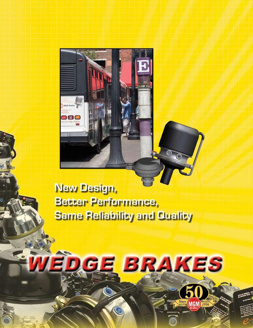
80
 MJW1216 (Magnum Performance Plus, Wedge).")
 CW (Service Wedge) Refer to Section 5 - SERVICE")

81 SECTION 6 Section 6: Wedge Spring Brakes Standard Stroke Models Page(s) MJW1216 (Magnum Performance Plus, Wedge) MJW1624 (Magnum Performance Plus, Wedge) (Replacement for MG1624T, P/N ) CW (Service Wedge) Refer to Section 5 - SERVICE CHAMBERS WEDGE FEATURES MJW Various Tube Lengths Available Light Weight, Rugged Aluminum Housing Epoxy-Coated Power Spring External Breather Tube Integral Release Bolt Polymer Push-Rod Guides Molded Nitrile Rubber Push-Rod Air Seal Low Friction Piston and Guide Heavy-Duty Nylon Reinforced Diaphragms Indicates Feature 79
82 MJW 1.75 Stroke Model MJW1216AT 1.75 Stroke Model Combination D VMRS# Single/Piggyback N/A B A Piggyback Plus Kit N/A WEDGE X C P/N Series MJW1216AT Model MJW1216AT Size 1216 Stroke 1.75 Push-Rod ArvinMeritor / Bendix P/N Combination (a) P/N Single/Piggyback N/A P/N Piggyback Plus Kit N/A Wt.Combination (Lbs.) Wt. Single (Lbs.) N/A A 7.90 B 5.84 C 5.70 D 6.44 E 1 3/4-12 UNC F Inlets 3/8 - NPTF X (a) SEE CHART E Standard Assembly Part Numbers Model Size MJW1216AT MJW1216 X Dimension ArvinMeritor Bendix 2.25 MJW1216AT052 MJW1216AT MJW1216AT053 MJW1216AT MJW1216AT054 MJW1216AT MJW1216AT055 MJW1216AT062 Note: (a) Refer to Standard Assembly Part Numbers Chart for mounting tube length variations. 80
83 MJW MJW1216AT Model 1.75 Stroke Model MJW Model Features Wide Choice Tube Lengths Lightweight, Rugged Aluminum Housing Epoxy-Coated Power Spring External Breather Tube Integral Release Bolt Polymer Push-Rod Guides Molded Nitrile Rubber Push-Rod Air Seal Low Friction Piston and Guide Heavy-Duty Nylon Reinforced Diaphragms Wedge Piston Assembly ArvinMeritor Bendix Ordering: Determine if foundation brake is ArvinMeritor or Bendix type by comparison to piston assembly photos above. Standard Service Kits Type MJW1216AT Stroke 1.75 X Dimension ArvinMeritor Bendix Replacement Parts P/N Series MJW1216AT Model MJW1216AT Part Description MGM P/N 1 Kit - Breather Tube WEDGE 2 Kit - Nuts & Bolts Clamp Band Assembly Kit - Diaphragm/Push Rod (a) 5 Diaphragm (a) 2 6 Push Rod (a) 3 7 Kit - Wedge Boot (a) 8 Spanner Nut Wedge Guide (ArvinMeritor) Piggyback N/A 11 Kit - NP Chamber Refer to Wedge Chamber service kits above 6 Note: (a) Diaphragm is glued to push-rod plate, therefore diaphragm and push-rod assembly are available only as part of item 11 kit. 11 For additional replacement parts, refer to Replacement Parts Section
84 MJW 2.00 Stroke Model MJW1624BT 2.00 Stroke Model Combination D VMRS# Single/Piggyback N/A B A Piggyback Plus Kit N/A WEDGE X P/N Series Model C MJW1624BT MJW1624BT Size 1624 Stroke 2.00 P/N Combination MJW1624BT156 P/N Single/Piggyback N/A P/N Piggyback Plus Kit N/A Wt.Combination (Lbs.) Wt. Single (Lbs.) N/A A 8.30 B 7.16 C 6.53 D 6.76 E 1 3/4-12 UNC Inlets 3/8 - NPTF X 4.50 E 82


 5 Diaphragm (a) 6 Push Rod (a) WEDGE 3 7 Kit - Wedge Boot 9004005 (a) 8 Collet Nut 8034005 9")

85 MJW MJW1624BT Model Tamper Resistant Design Lighter Weight Compact Size External Breather Tube Lower Hold-Off Pressure (Less Air Consumption) 2.00 Stroke Model Patented Integral Release Bolt Mechanism for Minimal Bolt Protrusion when manually released. Non-Coil Clash Power Spring Increased Corrosion Resistance - Steel Head Double-Coated with Clear Zinc Iron Chromate and Epoxy Release Bolt Patented Dual Thread Release Bolt design, an MGM Brakes exclusive, provides minimal bolt protrusion at maximum release. Replacement Parts P/N Series MJW1624BT Model MJW1624BT Part Description MGM P/N 1 Kit - Breather Tube Kit - Nuts & Bolts Clamp Band Assembly Kit - Diaphragm/Push Rod (a) 5 Diaphragm (a) 6 Push Rod (a) WEDGE 3 7 Kit - Wedge Boot (a) 8 Collet Nut Wedge Guide Piggyback N/A 11 Kit - NP Chamber No t e : (a) Diaphragm is glued to push-rod plate, therefore diaphragm and push-rod assembly are available only as part of item 11 kit. 11 For additional replacement parts, refer to Replacement Parts Section No t e : Product information and specifications subject to change without notice. 83 w w w.m g m b r a k e s.c o m

86
... 88-89 R8H (Remote Cylinder, Spring Applied, Hydraulic Release)... 88-89 MGM Brakes R4A & R5A Remote Mount Cylinders.")


87 Page(s) Section 7: Remote Mount Cylinders Standard Stroke Models SECTION 7 R4A (Remote Cylinder) R5A (Remote Cylinder) R5AHD (Remote Cylinder, Heavy-Duty R7A (Remote Cylinder, Air Applied, Spring Released) R8H (Remote Cylinder, Spring Applied, Hydraulic Release) MGM Brakes R4A & R5A Remote Mount Cylinders...are the original spring brake invented in the rugged logging country of Northern California. These cylinders were introduced by MGM Brakes in 1956 as the world s first spring-actuated parking and emergency brake actuators for commercial vehicles. These pull-to-actuate cylinders were designed for axle-mount using various weld-on and bolt-on mounting brackets and linkage arms. SAAR and SAHR drive-line brakes are developed as replacements for manually operated lever applied drive-line brakes. Mounted to the frame rail, the actuator utilizes a cable to apply parking force to a drum mounted on the drive-line. An optional electronic travel sensor provides the operator with information pertaining to the position of the push rod - applied or released. Today, these high-quality air-actuated cylinders have been adapted to such diverse non-automotive usage as dump truck end-gate actuators, emergency brake actuators on massive logging and commercial fishing winches and numerous other special applications. REMOTE CYLINDERS How Remote Mount Cylinders Operate When the end-gate is closed, spring pressure within the cylinders moves the latches into the latched position, reducing the risk the end-gate may inadvertently swing open. To unlatch the end-gate, the operator applies air to the cylinder through a valve located in the cab of the vehicle. As air pressure builds within the cylinder it forces the piston to move, compressing the spring(s) and extending the push-rod which moves the endgate latches into the open position. 85
 13.5 17.8 19.6 A 11.12 10.")
 is measured from lockpin hole in piston rod outward to rod end. Note that the lockpin hole appears from within the cylinder only after the cylinder is charged with minimum 85 psi air pressure.")
88 R4A, R5A & R5AHD Standard Stroke Model REMOTE CYLINDERS C C Note: (a) A B A B Remote D D VMRS# E E F Standard Assembly Part Numbers & Service Parts P/N Series Model R4A R5A R5AHD Size Stroke P/N Ext. 20 Rod N/A N/A P/N Ext. 15 Rod P/N Ext. 7 Rod Wt.Combination (Lbs.) A B C D Model R4A P/N Model R5A P/N Model R5AHD P/N Description Of Parts F X-dimension (7.00, etc.) is measured from lockpin hole in piston rod outward to rod end. Note that the lockpin hole appears from within the cylinder only after the cylinder is charged with minimum 85 psi air pressure. E F Inlets 3/4-16UNF x LONG 1/2-20UNF x 3.00 DEEP 3/8 - NPTF Remote Mount Cylinder - R4A (a) (External Thread on X - Dimension Rod) Remote Mount Cylinder - R4A (a) (External Thread on X - Dimension Rod) Remote Mount Cylinder - R4A (a) (Internal Thread on 7.00 X - Dimension Rod) Remote Mount Cylinder - R5A (a) (External Thread on X - Dimension Rod) Remote Mount Cylinder - R5A (a) (Internal Thread on 7.00 X - Dimension Rod) Remote Mount Cylinder - R5AHD (a) (External Thread on X - Dimension Rod) Remote Mount Cylinder - R5AHD (a) (Internal Thread on 7.00 X - Dimension Rod) Kit - Boot & Clamp - Remote Kit - Side Bushings R4A/R5A (for Trunnion Bolt Mount) 86

89 R4A, R5A & R5AHD Standard Stroke Models A A Assemblies Kit P/N and Quantities Model P/N Rod Specifications R4A External Thread R4A External Thread R4A Internal Thread R5A External Thread R5AHD External Thread R5A Internal Thread 7.00 R5AHD Internal Thread 7.00 Key P/N Part Description Gimbal Bracket - R4A Gimbal Bracket - R5A / R5AHD 1 1 1A Shock Pad - R4A A Shock Pad - R5A / R5AHD Trunnion Bolt A Star Lock Washer Extension Rod 1/2 UNF x Hex Nut 1/2 20 UNF Sliding Clevis 1/2 UNF Yoke Pin 1/ Cotter Pin Flat Washer 1/2 (inside diameter) Hex Nut 3/4 16 UNC Lockpin Washer 3/4 (inside diameter) Bolt Assembly (Frame Bracket) REMOTE CYLINDERS 87

90 R7A/R8H Pull-Type Actuators SAAR and SAHR Drive-line Brakes were developed as replacements for manually operated lever applied drive-line brakes on class 6 and 7 vehicles. Mounted to the frame rail, the actuator utilizes a cable to apply parking force to a drum mounted on the drive-line. An optional electronic travel sensor provides the operator with information pertaining to the position of the push rod applied or released. PRESSURE PORT E A SAHR A SAAR REMOTE CYLINDERS Model SAAR SAHR Series R7A R8H Part Number Stroke of Unit 2.75 min (69.8 mm) 2.75 min (9.8 mm) Normal Stroke 2.85 ±.10 in. (73.4 ± 2.5 mm) 2.85 ±.10 in. (73.4 ± 2.5 mm) Operating Pressure 130 PSI (9.0 Bar) 2320 PSI (160 Bar) Temperature Range -40ºF/+190º F (-40º C/+ 87.8º C) -40º F/+190º F (-40º C/+ 88º C) Weight estimated 6.91 lbs. ( 3.13 KG) 10 lbs. ( 4.53 KG) A in. (392.7 mm) in. (459.2 mm) B 6.51 in (165.4 mm) 9.10 in. (227.3 mm) C D E F G F D G E B SAHR B SAAR 8.94 in. (227.0 mm) 2.50 in. (63.5 mm) 4.50 in. (114.3 mm) 1.93 in. (49.0 mm) 1.20 in. (30.5 mm) C M10 x 1.5G INTERNAL THREAD 88


91 R7A/R8H SAAR, SAHR Model Features Compact Design Light Weight Aluminum Electronic Stroke Sensor SAHR MODEL SPRING APPLIED HYDRAULIC RELEASE SAAR MODEL SPRING APPLIED AIR RELEASE Service Kits & Replacement Parts Sensor Kit - SAAR & SAHR 1A Sensor Kit - Blue Diamond Cartridge - SAHR Hydraulic Unit Boot - SAAR 3A Boot - SAHR 1, 1A REMOTE CYLINDERS 2 3, 3A 89

92
93 SECTION 8 Section 8: Replacement Parts Diaphragms Kits - Push-Rod Assembly & Nut Yoke Assemblies Clamp Bands Kits - Breather Cap, End Cap & Weatherseal Plug Kits - S-Cam Protective Boot & Center Hole Shield Kits - Breather Tube & Elbow Non-Pressure Chamber (Without Breather Elbow) Non-Pressure Chamber (With Breather Elbow) Kit - Wedge Chamber Boot Kit - Nuts and Washers, Vent Hole-Plug Kit- Release Bolt Welded Yoke Assemblies Yoke Pins (Stainless Steel) NOTE: All parts except push-rod assemblies and non-pressure housings are packaged (on a card) or bulk packed in a box. Packaged parts are designated with a P suffix and bulk parts are designated with an X suffix. See price list for details. Page(s) REPLACEMENT PARTS 91
 16 2.25 8017116 R 6.00 (150 mm) 16LH 2.50 8017215 R 6.50 (165mm) 16L 2.50 8017216 R 6.00 (150 mm) 20 2.25 8017120 R 6.50 (165 mm) 20 2.25 8017145 N 6.50 (165 mm) 20L 2.50 8017220 R 6.")
 30 2.50 8017731 N 8.00 (200 mm) 30L3 3.00 8017830 R 8.00 (200 mm) 30L3 3.00 8017831 N 8.00 (200 mm) 36 3.00 8017836 R 9.00 (230 mm) 36 3.00 8017036 N 9.")
94 REPLACEMENT PARTS REPLACEMENT PARTS Note: Clamp Bands Diaphragms Type Stroke P/N Material Outside Diameter R 5.00 (130 mm) R 5.50 (140 mm) * R 5.50 (140mm) R 6.00 (150 mm) 16LH R 6.50 (165mm) 16L R 6.00 (150 mm) R 6.50 (165 mm) N 6.50 (165 mm) 20L R 6.50 (165 mm) R 7.00 (180 mm) 24L R 7.00 (180 mm) 24L N 7.00 (180 mm) 24L R 7.00 (180 mm) 24L N 7.00 (180 mm) R 8.00 (200 mm) N 8.00 (200 mm) 30L R 8.00 (200 mm) 30L N 8.00 (200 mm) R 9.00 (230 mm) N 9.00 (230 mm) (1) Material R is natural rubber blend with nylon fabric reinforcement. Use only R type diaphragms in extreme cold weather climates. Good to -65 F. (2) Material N is neoprene blend with nylon fabric reinforcement. (*) For use in MJ1216AT or MJS1216AT models only. See technical bulletin Note: Note: Note: Note: Note: Type 12 and 16 push-rods will provide an approx X- dimension when installed with 4.00 of 1/2-20 UNF threads. Type 20 through 36 push-rods will provide an approx X-dimension when installed with 8.00 of 5/8-18 UNF threads. These assemblies have MGM Brakes Stroke Alert markings and must be used only on the designated MGM Brakes units. (*) These assemblies to be used in conjunction with MGM 3-inch long stroke units only. B Push-Rod Assembly & Nut Kits Yoke Assemblies A C P/N A B C D E /8-18 UNF 1/2 9/ / /8-18 UNF 5/8 9/ / /2-20 UNF 1/2 9/ / /4-16 UNF 1/2 11/ / /4-16 UNF 5/8 11/ / * /8-18 UNF 1/2 9/ / /2-20 UNF 5/8 9/ / * /8-18 UNF 5/8 9/ / M16 x 1.5-6H 14 mm 14 mm 1 11/ M16 x 1.5-6H 1/2 9/ /16 (*) Stainless steel pin: 1/2 dim , 5/8 dim , see other stainless steel pins, page 94. D Type E P/N L L * L * Type P/N (1 Piece) P/N (2 Piece) Note: All clamps furnished with nuts and bolts. Breather Cap, End Caps & Weatherseal Plug Kits Key P/N Description Used on MGM Models/Sizes Breather Cap Assembly All WM, WL and MB Kit - Weatherseal Plug TR, TR-T, sizes 2024, 2424L, 2430L, 3024, 3030, TR-TS, sizes 2424L, 2430L, Kit - Weatherseal Plug TR, TR-T, TR-TS sizes, 3036, End Cap & Retainer All L-T, MB-T and MG-T 92


 MGM P/N 9065002 Kit is suitable only for MGM Brakes Type 20, 24, 30 & 36 non-pressure chambers.")

 Type P/N 16 9015163 20* 9015110 24* 9015151 30 9015122 36 9015108 2 Note:")
95 REPLACEMENT PARTS S-Cam Protective Boot & Center Hole Shield Kits Key P/N Description Boot & Retainer S-Cam Boot & Retainer S-Cam Kit - Center Hole Shield Boot Center-Hole Note: (1) MGM P/N Kit can only be used with non-pressure chambers (mounting housings) having an embossed bottom essentially shaped like the retaining plate for the boot. (2) MGM P/N Kit can only be used with MGM Brakes Type 20, 24 & 30 non-pressure chambers (mounting housings) with flat bottoms having 3 equally spaced installation holes for the plastic boot retainer. (3) MGM P/N Kit is suitable only for MGM Brakes Type 20, 24, 30 & 36 non-pressure chambers. Field installation requires complete disassembly of the service brake chamber. (4) MGM P/N is suitable for MGM Brakes type 20, 24, 30 & 36 non-pressure chambers with center hole and 5/8 rod only. Vent Hole-Plug Vent Hole - Plug P/N Breather Tube & Elbow Kits Key P/N M3030B-T M3036B-T M3636B-T 1 Service MGM Brakes Model All MGM Brakes model sizes fitted with breather tube except those listed below Non-Pressure Chamber (With Breather Elbow) Type P/N * * Note: (*) These chamber sizes are heavy-duty weld-reinforced. (**) 8-Gauge NPC with welded bolts. Kit - Wedge Chamber Boot Vent Hole Note: Do not plug more than 3 holes in the service chamber (NPC) and never plug any hole facing the road surface or positioned at the lowest point. Non-Pressure Chamber (Without Breather Elbow) Type P/N * * ** REPLACEMENT PARTS P/N Kit - Nuts & Washers ( NPC Mounting ) P/N Type 20, 24, 30 & 36 P/N Type 12 and 16 93


96 REPLACEMENT PARTS Welded Yoke Assemblies 1.3 Pins Not Shown REPLACEMENT PARTS 1 & Type Long Stroke - Y Dim. = 2.25 P/N Kit - NP Chamber Kit - Push-Rod / Welded Yoke Kit - Chamber Assembly Type Long Stroke - Y Dim. = 2.25 P/N Kit - NP Chamber Kit - Push-Rod / Welded Yoke Kit - Chamber Assembly Kit - Release Bolt Key P/N Services MGM Brakes Model Sizes 4 2 & TR2024, TR2424L, TR2430L,TR3024 and TR M20B-T, M24B-T, M30B-T and M1216G-T M36B-T and all MG-T models except M1216G-T TR3036, TR3636 Yoke Pins (Stainless Steel) Diameter P/N 1/ (Forged Yoke) 5/ (Forged Yoke) 1/ (Welded Yoke) 1/ (Welded Yoke) 94
97 NOTES REPLACEMENT PARTS 95

98 96
99 TRANSIT / SPECIAL APPLICATIONS SECTION 9 Page(s) Section 9: Transit / Special Application TR, TR-T, TR-TS and MJS Transit Bus Brakes and other special applications


100 TRANSIT / SPECIAL APPLICATIONS Special Transit Length Push-Rods VMRS # Available aftermarket options & part numbers for assemblies requiring X dimensions longer than standard 8.00 fully threaded push-rod. All Models Type 24 Type 30 Type 36 TRANSIT / SPECIAL APPLICATIONS X Dimension Push-Rod Diameter 5/8 3/4 5/8 3/4 5/8 3/4 Threaded Length Part Number Designator xxxx551 xxxx651 xxxx551 xxxx651 xxxx551 xxxx651 Kit - Push-Rod Assembly TR-T Model TR-LP3T Model LTR-L3 Model MJS Model Note: For yoke pin and mounting hardware replacement parts refer to Section 8. For custom replacement assemblies, contact MGM Brakes Sales. 98
101 NOTES TRANSIT / SPECIAL APPLICATIONS 99

102 NEW TAB PAGE
103 SECTION 10 Page(s) Section 10: e STROKE Electronic Stroke Alert System Overview Wiring Diagrams & Components Tractor/Truck/Bus Sample System Trailer Sample System Replacement Parts Promotes SAFETY Check Brake Stroke Status & Pinpoint Brake Problems Wheel- & Problem-Specific Monitoring in Real Time Diagnostic Tool Chassis Communications Module (CCM) with Easy-to-Read Green/Red/Orange LEDs and a Concise Blink Code Listing on Unit System Status Indicator CCM is Environmentally Sealed Completely Potted & Sealed to Keep Out Dust, Water & Contaminants Stroke sensing magnetic components are factory installed and pre-calibrated as an integral part of the MGM Brakes service and spring brake chambers. Sensors are field replaceable. FEATURES Durable Cables Made from Heavy-Gauge Wire & Water-Proof Connectors Ensure Reliable Operation Highly Accurate, *Patented Design Operating Temperature: -40 F to +176 F (-40 C to +80 C) *U.S. Patent Nos. 5,450,930, 5,825,287 and 6,255,941, and other U.S. and Foreign Patents Pending. e STROKE ELECTRONIC STROKE ALERT 101

104 SYSTEM OVERVIEW e STROKE Brake Monitoring System e STROKE ELECTRONIC STROKE ALERT Sensor Assembly The MGM Brakes e STROKE system provides a quick, accurate brake stroke status reading for any air-braked vehicle with exposed push-rod brake chambers. The easy-to-read, conveniently placed Chassis Communications Module (CCM) produces specific LED blink codes that pinpoint existing brake problems, including an overstroke condition, dragging brakes and/or non-functioning actuators. E stroke sensing magnetic components are factory pre-installed and pre-calibrated as an integral part of MGM Brakes service chambers and spring brakes, helping to keep them from the elements and out of harm s way. This unique, patented design eliminates the accuracy, reliability and durability issues inherent with an externally-mounted sensor system. Good preventive maintenance can significantly lower parts and labor costs. The e STROKE system is an excellent diagnostic tool to find and remedy brake problems before they become serious and costly. Keeping a vehicle s braking system in optimal condition and adjustment also reduces the risk of receiving expensive out-of service citations during official inspections, further reducing costs. The e STROKE system s ease-of-use promotes operational safety always a serious concern. Conduct a brake stroke status check during a pre-trip walk-around inspection and discover problems before getting on the road, without having to crawl underneath the vehicle. Real time monitoring is also possible with the CCM mounted inside the vehicle the LEDs display constant feedback as the vehicle is driven and the brakes are applied. With e STROKE, knowing the state of a vehicle s braking system is very easy. e STROKE warnings can lead to the discovery of: Soft or broken return spring in foundation brake or actuator Worn bushings (cam tube or spider brake) Poor automatic slack maintenance Improper parking brake release by operator Brake drum expanded by overheating Drum warpage or out-of-round condition Excessive mechanism deflection Defective or worn spring brake Broken parking brake power spring Brake adjustment done incorrectly Low voltage system Clamp Ring Magnetic Sleeve Stone Shield SPECIFICATIONS: Chassis Communications Module (CCM) Dimensions: 7 W x 3.75 H x 2 D Weight: 2 ± 0.5 lbs. Power: 9.5 to 30 VDC Cable Connectors: Metri-Pack Sealed 150 & 280 Series, IP66 rated Sensor/Cable Assembly Power: 5 VDC supplied by CCM Sensor Cable Lengths: 8 to 60 SAE J1128 and J2202 requirements Cable Connectors: Metri-Pack Sealed 150 Series, IP66 rated Operating Temperature: -40 F to +176 F. Specifications subject to change. To find out how e STROKE can help reduce your fleet operating costs, whether truck, trailer or bus, contact MGM Brakes Customer Service at: (800)

105 STROKE WIRING DIAGRAMS & COMPONENTS Tractor/Truck/Bus System 3-Axle (Sample*) Trailer System 2-Axle (Sample*) RIGHT REAR METRI-PAK 150 MALE 3 PIN CONNECTOR METRI-PAK 280 FEMALE 4 PIN CONNECTOR METRI-PAK 280 MALE 4 PIN CONNECTOR EXISTING ABS BLUE LINE EXISTING ABS BLUE LINE e STROKE ELECTRONIC STROKE ALERT 1. INSTALL STRAIN RELIEF BRACKET (ITEM 4) BETWEEN MOUNTING NUT AND WASHER ON TOP MOUNTING BOLT OF BRAKE UNIT (ITEMS 2 & 3). 2. SECURE EACH SENSOR CABLE (ITEM 5) TO STRAIN RELIEF BRACKET (ITEM 4) WITH WIRE TIE (ITEM 6) SUPPLIED WITH STROKE ALERT SYSTEM. ITEM QTY DESCRIPTION 1 1 CHASSIS COMMUNICATION MODULE 2 4 TANDEM SPRING BRAKE 3 4 HARNESS, SENSOR BRACKET, STRAIN RELIEF - SUPPLIED WITH BRAKE UNITS SENSOR ASSEMBLY WIRE TIE - SUPPLIED WITH BRAKE UNIT CABLE, TRAILER, ABS BREAKOUT CABLE, TRAILER ABS T-BREAKOUT W/BRAKE LIGHT & ABS FAIL *IMPORTANT NOTE: Specifications, components & wiring configurations shown above are for typical sample illustrative purposes ONLY. 103


106 REPLACEMENT PARTS e STROKE ELECTRONIC STROKE ALERT CCM Truck / Tractor / Bus Part Number Description CCM 2 Axle Truck / Bus CCM 2 Axle Tractor CCM 3 Axle Tractor Power Cables - Truck / Tractor / Bus Part Number Length (ft.) Description CCM Power Connect Lead CCM Power Cable CCM Power Cable CCM Power Cable CCM Power Cable SAE J1708 Harness Pressure Transducer Harness - Truck / Tractor / Bus Part Number Length (ft.) Description Pressure Transducer Harness Pressure Transducer Harness Pressure Transducer Harness Pressure Transducer Harness Actuator Sensor Harness - Truck / Tractor / Bus /Trailer Part Number Length (ft.) Description Sensor Harness Sensor Harness Sensor Harness Sensor Harness Sensor Harness Sensor Harness Sensor Harness Sensor Harness Sensor Harness Sensor Harness Sensor Harness Sensor Harness CCM Truck / Tractor / Bus CCM Power Connect Lead Truck / Tractor / Bus Power Cables Truck / Tractor / Bus Pressure Transducer Harness Truck / Tractor / Bus Actuator Sensor Harness Truck / Tractor / Bus /Trailer 104
 Description 8290116 30 Actuator Sensor 8290120 60 Actuator Sensor Pressure Transducer - Truck / Tractor / Bus Part Number Description 8090075 Pressure Transducer Miscellaneous Parts (not shown)")
 Description 8090040 N/A Tie Wraps 8090058 N/A Labels 9090106 12 Warning Light Harness CCM - Trailer Part Number Description 8290034 CCM 1 Axle Trailer 8290035 CCM 2 Axle Trailer 8290036 CCM 3 Axle")

107 REPLACEMENT PARTS Actuator Sensor - Truck / Tractor / Bus /Trailer Part Number Length (in.) Description Actuator Sensor Actuator Sensor Pressure Transducer - Truck / Tractor / Bus Part Number Description Pressure Transducer Miscellaneous Parts (not shown) Part Number Length (ft.) Description N/A Tie Wraps N/A Labels Warning Light Harness CCM - Trailer Part Number Description CCM 1 Axle Trailer CCM 2 Axle Trailer CCM 3 Axle Trailer Bracket - Mounting (Optional) ABS T Power Breakout Adapter - Trailer Part Number Length (ft.) Description Power Breakout Adapter Power Cables - Trailer Part Number Length (ft.) Description Trailer ABS Power Cable Trailer ABS Power Cable Trailer ABS Power Cable Trailer ABS Power Cable Trailer ABS Power Cable Trailer ABS Power Cable Trailer ABS Power Cable Actuator Sensor Truck / Tractor / Bus /Trailer Pressure Transducer Truck / Tractor / Bus CCM - Trailer CCM Mounting Bracket ABS T Power Breakout Adapter - Trailer Power Cables - Trailer e STROKE ELECTRONIC STROKE ALERT ANYTIME. ANYWHERE. ANY WEATHER. 105

108
109 SECTION 11 Page(s) Section 11: Technical Information Model Application Chart Hexavalent Chromium Replacement Product Identification Plate Long Stroke Identification Double-Diaphragm to Piston Conversion Chart Procedure to Cut a Push-Rod Proper Brake Adjustment Fastener Torque Value Chart Procedure to Lengthen External Breather Tube Mixing Standard and Long Stroke Chambers Field Replacement of Chambers Equipped with Welded Yokes Actuators Manufactured With Neoprene Diaphragms Performance Chart - Spring Brake Chambers (including Remote Mount Cylinders) Performance Chart - Service Brake Chambers TECHNICAL 107
110 MODEL APPLICATION CHART MGM Brakes manufactures a wide variety of spring brakes, many designed specifically for niche applications. While all MGM models are engineered for the longest life and most reliable service, choosing the right spring brake for a particular application is crucial to ensuring maximum value. APPLICATION MGM Brakes Spring Brake Application Matrix: This matrix is intended for use as a general information guide only. If you have any questions concerning the application of any particular MGM Brakes model, contact your local MGM Brakes representative for assistance. TR TR-HD TR-T TR-THD TR-THDW TR-TS TR-TSHD TR-TSHDW TR-LP3 TR-LP3HD TR-LP3T TR-LP3THD TR-LP3THDW TR-LP3TS TR-LP3TSHD TR-LP3TSHDW LTR-T LTR-L3 MJ-ET ACIDS / LIQUID CORROSIVES X X X X X DRY BULK CHEMICALS X X X X X X DUMP TRUCK X X X X X X FERTILIZER X X X X X X X FIRE & EMERGENCY X X X X TECHNICAL LINE HAUL X X X X X LIVESTOCK / POULTRY X X X X X X LOGGING X X X X X PETROLEUM PRODUCTS X X X X X X READY-MIX CONCRETE X X X X X X X REFUSE X X X X X SALT TRUCK X X X X X X X SCHOOL BUS X X TOXIC WASTE X X X X X X X X X TRANSIT X X X X X X X X X 108
111 HEXAVALENT CHROMIUM REPLACEMENT 1.0 PURPOSE: To notify customers of coating conversion from current Yellow Zinc Dichromate (hexavalent chromium) to clear trivalent chromate. 2.0 BACKGROUND: Hexavalent chromium is used in surface coatings for corrosion protection in many vehicle components. On February 28, 2006, the U.S. Department of Labor, Occupational Health and Safety Administration (OSHA) issued final rule concerning Hexavalent chromium. The OSHA directive stated that Hexavalent chromium was a carcinogen and set new limits for exposure to this hazardous material. The European Union s directive 2000/53/ EC [1] known as the End of Life Vehicle Directive (ELVD) governs permissible use, reuse, recycling, and recovery of end-of-life vehicles and their components. The objective of the ELVD is to encourage vehicle manufacturers to limit the use of hazardous materials in their products. Hexavalent chromium is one of the materials controlled by the ELVD, which calls for a total phasing out of hexavalent chromium coatings by July SCOPE: Hexavalent chromium is a key component of the yellow zinc dichromate plating used for corrosion protection on clamp bands, clamp band bolts, continuous rings, and other hardware. MGM Brakes will be replacing the yellow zinc dichromate coating on all components with a trivalent zinc chromate. 4.0 TIMELINE: The new trivalent zinc chromate coating will be phased into production beginning in early APPEARENCE: The new coating will be clear or clear with a blue tint. 6.0 CORROSION PROTECTION: The new coating will offer equal or greater salt spray protection when compared to yellow zinc dichromate. TECHNICAL YELLOW SILVER YELLOW ZINC DICHROMATE (HEXAVALENT CHROMIUM) CLEAR TRIVALENT CHROMATE 109

 models the I.D.")

")
112 PRODUCT IDENTIFICATION PLATE All MGM brake actuators made after October have an aluminum identification plate attached to the actuator which contains the MGM Brakes part number, date code, and often a customer part number. On all TR, LTR and MJ (Magnum Performance Plus) models the I.D. plate is attached to the center section aluminum casting. On all C, CS and CW models the I.D. plate is attached to the pressure cap or to the clamp band. See the illustrations below for I.D. plate locations. MGM M XXXXXXXXXXX MGM Brakes Part Number Date Code Customer Part Number (optional) TECHNICAL Double Diaphragm TR Model Long Life Double Diaphragm LTR Model Piston Magnum Performance Plus Model MJS Model Wedge MJW Model Remote Cylinder S-Cam Service C and CS Models 110

113 LONG STROKE IDENTIFICATION LONG STROKE SPRING BRAKE IDENTIFICATION SQUARE PORTS ARE CAST RIGHT INTO THE FLANGE CASE TO ENSURE TAMPER-RESISTANT IDENTIFICATION THAT IS PRONOUNCED AND EASILY DETECTABLE. TECHNICAL SQUARE EMBOSSMENT IS RAISED A FULL HALF-INCH FROM THE TOP OF THE PRESSURE CAP TO ENSURE TAMPER- RESISTANT IDENTIFICATION THAT IS PRONOUNCED AND EASILY DETECTABLE 111
114 DOUBLE DIAPHRAGM TO PISTON CONVERSION CHART 1.0 PURPOSE: The purpose of this technical bulletin is to recommend a MJ-ET piston type air brake actuator replacement for various MG-T s and double diaphragm models. CAUTION: The recommended MJ-ET replacement may have more parking force than the model it is replacing. An anti compounding valve may be required to prevent excess braking torque. Note: The J-Series (Magnum Performance Plus) models listed on the chart below are 3.00 inch stroke actuators. Ensure that installations have proper clearance for 3.00 inches of stroke. MGM Brakes recommends replacing both brakes on an axle if force and/or stroke is different than unit being replaced. 2.0 CROSS REFERENCE CHART: The following chart provides an easy cross reference for selecting a MJ-ET piston type air brake actuator to replace a MG-T or double diaphragm air brake actuator. 3.0 MODEL NUMBER DEFINITIONS: Model numbers for double diaphragm air brake actuators describe the diaphragm size. A model TR2430 describes a type 24 service chamber diaphragm and a type 30 spring chamber diaphragm. Model numbers for piston type air brake actuators describe the service chamber diaphragm size and a level of parking chamber force. A model M2420LG-T describes a type 24 service chamber diaphragm and a parking chamber having 1410 lbs. ± 10% force output at 1.25 inch stroke (see chart below). (A) (B) Hold-Off Pressure (psig) is measured as decreasing air pressure at.200 inch of full OFF stroke position (zero stroke). Parking Force (lbs. ± 10%) is measured at 1.25 inches of stroke. TECHNICAL Model Size Stroke (Inches) Parking Force (B) Hold-Off Pressure (A) TR2430HD lbs. 68 psig TR3030HD lbs. 68 psig TR lbs. 63 psig MJS1724 MJS2024 MJS lbs. 71 psig MJS3024 MJS2028 MJS2428 MJS lbs. 73 psig MJS3628 MJS2030 MJS2430 MJS lbs. 75 psig MJS3630 TR2430HD lbs. 68 psig TR lbs. 63 psig TR3030HD lbs. 68 psig TR lbs. 66 psig TR lbs. 68 psig LTR lbs. 71 psig LTR lbs. 71 psig M1620LG-T lbs. 50 psig M1624LG-T lbs psig M2020LG-T lbs. 50 psig M2024LG-T lbs psig M2030LG-T lbs psig M2420LG-T lbs. 50 psig M2424LG-T lbs psig M2430LG-T lbs psig M3024GT lbs 60 psig M3027GT lbs. 67 psig M3031GT lbs. 69 psig Note: Contact MGM Brakes Sales for model s not specified above. 112


115 PROCEDURE TO CUT A PUSH-ROD PROCEDURE: TO CUT THE SERVICE PUSH-ROD TO PROPER LENGTH! Warning: Do not attempt to service or dissemble the spring chamber or any spring brake actuator. A large spring in the spring chamber having extreme force could cause serious bodily injury if it were suddenly released due to inadvertent removal of this clamp or tamper-resistant head. IMPORTANT: Place blocks under wheels to prevent vehicle runaway before removing air brake actuators. (a) (b) REMOVE WORN OR NON-FUNCTIONAL UNIT FROM VEHICLE. Determine manufacturer and model of unit to be replaced. Refer to that manufacturer s service manual for caging and removal instructions. Make sure the spring chamber of the removed actuator is fully released (power spring caged) and the service brake push-rod is fully retracted to zero stroke position (i.e. brake fully released). (c) Measure and record the X and Y dimensions (Figure 1). X Dimension - The dimension from bottom of actuator to end of push-rod. Y Dimension - The dimension from bottom of actuator to centerline of yoke pin. Figure 1 Figure 2 X Y NOTE: If for some reason the spring chamber power spring cannot be caged and fully released, then the X and Y dimensions will need to be measured from another actuator of the exact type from the same vehicle provided it is retracted to its zero stroke position (brake fully released) and was operating correctly. (d) Before marking push-rod to be cut on a new unit, be sure the spring chamber and push-rod are fully retracted to the zero position. (This may be done with the manual caging bolt or by applying psi air pressure to the spring chamber air inlet port.) TECHNICAL (e) (f) Take measured X dimension from the removed unit and mark push-rod of new unit from the bottom of the actuator. Thread yoke jam nut past mark on push-rod. Align bottom edge of nut with mark. (g) Use a sharp hack-saw and cut push-rod on the mark (Figure 2). (h) (i) (j) After cutting rod, thread jam nut off to clean up the thread. Thread yoke onto the push-rod. Yoke from removed unit may be reused provided yoke pin hole is not worn. Adjust yoke to the same Y dimension as measured from the removed unit. Hold yoke to prevent it from turning and tighten jam nut against yoke Lbs.-Ft. torque. TO INSTALL NEW UNIT ON VEHICLE: Refer to MGM Brakes Service Manual for the model that is being installed. 113

. Stroke should be as short as possible with no lining to drum contact.")

116 PROPER BRAKE ADJUSTMENT NOTE: The last half of an air chamber stroke is less efficient than the first half. Therefore, the following adjustments are recommended for maximum efficiency when using manually adjusted slack adjusters. BRAKES OFF - NOT APPLIED PROPERLY - ADJUSTED BRAKES ON - APPLIED Angle must always be greater than 90 due to various slack adjuster lengths and installation setups. (Refer to axle or OEM manufacturer s manual for recommended angle). Stroke should be as short as possible with no lining to drum contact. To check brake adjustment, apply 90 to 100 psi air pressure to the service chamber. Consult the vehicle manufacturer for the correct angle between the slack adjuster arm and push-rod and/or the push-rod length. This is necessary since different dimensions are required for automatic or manual slacks, various slack lengths and different slack adjuster manufacturers. TECHNICAL IMPROPERLY ADJUSTED BRAKES ON - APPLIED Maximum recommended readjustment stroke has been exceeded) MGM Brake Stroke Alert (Excessive Stroke Warning) See chart for recommended readjustment stroke Type Effective Area (SQ. IN.) Approx. Diaphragm O.D. Inches MM Rated Stroke of Chamber Inches MM Maximum Stroke with Brakes Adjusted B MV/MA Recommended Readjustment Stroke Inches SHOULD BE AS SHORT AS POSSIBLE L WITHOUT LINING TO DRUM L CONTACT L L L SOURCE: MVMA (Motor Vehicle Manufacturers Association) Note: The push-rod must remain perpendicular to the bottom surface of the non-pressure chamber (NPC) within ±3 zero to full stroke. MM! IMPORTANT RECOMMENDED SPRING BRAKE ACTUATOR DISARMING PROCEDURE Warning: This procedure must be strictly adhered to. Never attempt to remove the spring chamber clamp ring from a double diaphragm actuator or the spring chamber retaining ring from a piston actuator. Both actuators employ a high energy power spring that could cause serious bodily injury if the spring were suddenly released due to improper disassembly. All retired spring brake actuators must be safely disarmed before they are disposed of to prevent serious personal injury from accidental sudden release of the high energy spring (as much as 2700 Lbs. of force) in the parking chamber. To disarm the unit, remove it from the vehicle following the instructions in the MGM Brakes Service Manual. Be sure to release the brake per Section (2) of the MGM Brakes Service Manual. Never attempt to remove the head which contains the power spring. Observe all safety precautions. Place the unit in a steel *container and use an acetylene torch to cut a hole through the head housing the power spring. Cut completely through at least two spring coils. The steel container must have openings to expose the head where it is to be cut with the acetylene torch and it must be strong enough to prevent parts from hurtling out should the unit suddenly separate before it is safely disarmed. It is the users responsibility to ensure the steel container is safe. *Information concerning a suitable container is available through your MGM Brakes Representative. 114
117 FASTENER TORQUE VALUE CHART BOLT TORQUES Component Bolt Size Foot/Pounds of Torque Newtons/Meters of Torque Release Bolts Caging TR Models 1/2-13 UNC TR Models 5/8-11 UNC L Models 5/8-11 UNC J Models 5/8 18 UNF / 1/2-13 UNC 74 Max. 100 Max. M Models 3/8-24 UNF M Models 1/2-20 UNF Storage TR Models 1/2-13 UNC TR Models 5/8-11 UNC L Models J Models M Models (MG-T) Clamp Band NUTS AND BOLTS Yoke Nuts 5/16-24 UNF /8-16 UNC /2-20 UNF /8-18 UNF /4-16 UNF M16 X 1.5-6G TECHNICAL Mounting Nuts & Bolts 7/16-14 UNC /8-11 UNC /8 18 UNF M16 X 1.5-6G Air Inlet Fittings 3/8 NPTF /8-24 UNF M16 X 1.5-6H ! Warning: Do not use impact wrench. 115
118 PROCEDURE TO LENGTHEN AN EXTERNAL BREATHER TUBE 1.0 Purpose: To provide a procedure to add a tube section to lengthen a breather tube in the field when the single/piggyback is rotated to repostion the ports relative to the non-pressure chamber housing. 2.0 Scope: All MGM Brakes models with an external breather tube. 3.0 Material required: Rubber extension tube Adhesive (Loctite #414 Superbond) or equivalent 4.0 Procedure: 4.1 Cut breather tube approximately half way between the rubber elbows. 4.2 Using the recommended procedure in the MGM Brakes Service Manual, loosen the service chamber clamp and rotate the piggyback to the desired position. Tighten service chamber clamp. TECHNICAL 4.3 If necessary, cut rubber extension to a length that will insure a minimum of ½ inch engagement over both ends of the cut breather tube. 4.4 Apply an adhesive to both ends of the cut breather tube. 4.5 Slip the rubber extension over both ends of the cut breather tube a minimum of ½ inch. 5.0 Using the recommended procedure in the MGM Brakes Service Manual, check the service chamber clamp for leaks.! WARNING: Do not remove the spring chamber clamp ring (clamp closest to the release bolt) as serious injury may result from sudden release of the power spring. 116
119 MIXING STANDARD AND LONG STROKE CHAMBERS 1.0 Scope: Installing and replacing brake chambers with different rated strokes specifically long stroke versus standard stroke. 2.0 Recommendation: MGM Brakes recommends replacing chambers with the same stroke rating across an axle. When servicing a truck/trailer equipped with either standard stroke or long stroke chambers, it is crucial that replacement of the chambers be like for like. For example: if a 3-inch stroke chamber is to replace a 2.5-inch stroke chamber, both chambers on that axle must be upgraded to 3-inch chambers. CAUTION: When upgrading from standard stroke to long stroke chambers, be sure there is: ) adequate clearance for the increased stroke of the pushrod, yoke, and slack adjuster at full stroke ) adequate clearance of the longer chamber at the worst case suspension and steering articulation. Approval from the original vehicle manufacturer for proper clearance is recommended. 3.0 Background: The heat generated by the contact of the lining against the drum, especially during hard or continuous braking situations, causes the drum to grow, or expand. The ability of a 2.5-inch standard stroke chamber to provide adequate pressure of the lining against the ever-expanding drum is limited by the stroke and performance characteristics of the brake. As the 2.5-inch stroke chamber exceeds 2-inches of travel, the operator will begin to sense the brake fade phenomenon, which will become more prevalent as the chamber moves closer to it s maximum travel position, at which point the brake will cease to provide any braking capability. However, the performance and operational characteristics of the MGM 3-inch long stroke chamber provides braking force beyond the point where the 2.5-inch standard stroke chamber ceases to provide braking. The 3-inch long stroke chamber provides the same force-output at 2.5-inches of stoke as provided by the standard chamber at 2-inches of stroke. TECHNICAL Therefore, because of the differences in the operational characteristics of the standard and long stroke chambers, when they are mixed across an axle, an imbalance may exist in the stopping capability of the vehicle at strokes beyond the recommended readjustment limit of the standard stroke chamber. This may result in the vehicle being pulled toward the side of the long stroke chamber, which is doing the majority of the braking. This may go unnoticed by the driver during normal brake applications, but could cause vehicle instability during emergency braking. 117
120 FIELD REPLACEMENT OF CHAMBERS EQUIPPED WITH WELDED YOKES Every day, more and more vehicles are being manufactured with 3-Inch long stroke spring brakes and service chambers with the yoke welded to the service push rod. Because the welded yoke is permanently attached to the push-rod, it is virtually impossible to remove and re-use it. Therefore, unless the non-pressure housing (mounting base), push-rod, and/or yoke have been damaged, or are severely worn, MGM Brakes recommends replacement of the single/piggyback unit only. However, if replacement of the combination/tandem unit is required, it is recommended that a unit equipped with a welded yoke be used. 1.3 Welded Yoke Units manufactured with a welded yoke have a preset Y dimension, measured from the bottom of the NPC to the centerline of the yoke pin, of 2.25-inches. Because the Y dimension is relatively short, the corresponding X dimension, measured from the bottom of the NPC to the end of the rod, will also be short, at approximately ¾ of an inch. Consequently, if a replacement unit with a universal all-threaded cut-to-fit push rod is used, the stack-up of the yoke and jam nut will exceed the X dimension by approximately 1/8 th of an inch. TECHNICAL Forged Yoke & Jam Nut In some cases, this will prevent the unit from achieving zerostroke, or, if the push rod opening in the NPC is large enough, the jam nut will protrude into the NPC and may damage the protective stone shield. Spring brakes and service chambers must fully retract to zero-stroke in order to completely release the foundation brakes so the lining no longer contacts the drum, and to allow the automatic slack adjusters to properly operate and adjust the stroke. Therefore, do not use a replacement unit with a universal all-threaded cut-to-fit push rod to replace a unit with a welded yoke. NOTE: Be sure to always replace like for like. Do not mix 2.5-inch standard stroke chambers with 3-inch long stroke chambers across an axle. Reference MGM Technical Bulletin on page
121 ACTUATORS MANUFACTURED WITH NEOPRENE DIAPHRAGMS MGM Brakes manufactures a limited line of service chambers and spring brakes with Neoprene diaphragms for severe service applications where petroleum saturated contaminants may enter the air system and come into contact with the diaphragms. While Natural Rubber diaphragms may resist the negative effects of oil and oil saturated contaminants for a period of time, Neoprene diaphragms have proven to be more durable. Manufactured from a combination of materials that insure superior strength, flexibility and resistance to degradation due to contact with oil and other chemicals, Neoprene diaphragms are a great option when the air system is prone to contamination from oil. The following is a list of MGM Neoprene diaphragm equipped service chambers and spring brakes: PART # MODEL DESCRIPTION C20 Service Chamber C24L Service Chamber C36 Service Chamber TR3030LP3 Combination TR3030 Piggyback Plus Kit X TR3030 Piggyback Plus Kit Bulk Pack 20 Pcs/Box TR3030 Combination X TR3030 Combination Bulk Pack 20 Pcs/Box TR3030T Piggyback Plus Kit TR3030T Combination TR3636T Combination TR3030S Combination TR3030TS Piggyback TR3030TS Combination TR3030TSHD Combination TR3030LP3TS Combination MJS3024ET851 MJS3024ET Combination MJS3628ET851 MJS3628ET Combination NOTE: If other sizes are required, contact your local sales representative for availability. TECHNICAL 119
122 PERFORMANCE CHART - SPRING BRAKE CHAMBERS MODELS Service Chamber Size Spring Chamber Size Rated Service Stroke (in) Max. Service Stroke (in) Vol. 100 psi (in) (a) Hold-Off Pressure Required (psi) (b) Spring Brake Force-Output (Pounds-Force) at Inches of Stroke (c) (d) (in) Pounds of Torque Applied at 1.25 Stroke by S-Cam Camshaft w/slack Adjuster Length of (in) (**) Spring TR S-Cam TR2030LP TR2424L 24 S-Cam TR2430L TR2430LHD 24 S-Cam TR2430LP TR2430LP3HD TR S-Cam TR TR3030HD TR3030LP TR3030LP3HD TR TR S-Cam LTR2430T 24 S-Cam LTR2430L TECHNICAL LTR3030T 30 S-Cam LTR3030L Note: (*) Indicates piston-type design in the spring chamber. (**) Brake chambers with 2.00 or less rated stroke calculated at 1.00 stroke. (a) Spring chamber measured at full OFF (zero) stroke and service chamber measured at maximum ON stroke. Reference SAE J1469. (b) Measured as decreasing air pressure required to activate spring chamber to within 0.20 inch (5 mm) of full OFF (deactivated) stroke. (c) Measured at end of service chamber push-rod using power springs which have been held compressed to assembly shut height for 24 hours to remove initial false load. Forces shown are nominal performance (+/- 10%) for all spring chamber model sizes. (d) Refer to the following pages for performance characteristics of all MGM service brake chamber sizes (pgs ) Performance levels shown hold true for all design versions of the same model size. For example...read the same performance for Models TR3030T and TR 3030TS as shown above for Model TR
123 PERFORMANCE CHART - SPRING BRAKE CHAMBERS Model Service Chamber Size Spring Chamber Size Rated Service Stroke (in) Max. Service Stroke (in) Vol. psi Hold-Off Pressure Required (psi) (b) Spring Brake Force-Output (Pounds-Force) at Inches of Stroke (c) (d) (in) Pounds of Torque Applied at 1.25 Stroke by S-Cam Camshaft w/slack Adjuster Length of (in) (**) Spring MJS1216AT* S-Cam MJS2424ET* 24 S-Cam MJS3024ET* MJS3028ET* MJS3030ET* MJS3628ET* 36 S-Cam MJS3630ET* MJW1216AT REMOTE MOUNT CYLINDERS Spring Brake Force-Output (Lbs.-Force) at Inches of Stroke Model - - Rated Stroke (in) - - Hold-Off Pressure R4A R5A R5AHD R7A R8H TECHNICAL 121
124 PERFORMANCE CHART - SERVICE BRAKE CHAMBERS Rated Stroke & Air Volume Model Type Rated Service Stroke (in) Vol. 100 psi Rated Service Stroke (cubic in) Application Pressure of (PSI) Service Brake Force-Output (Pounds-Force) at Inches of Stroke (in) Pounds of Torque Applied At Mid-Stroke by S-Cam Camshaft w/slack Adjuster Length of (in) TR2024 S-Cam TR24xxL S-Cam TR24xxLP3 S-Cam TECHNICAL TR30xx S-Cam TR30xxLP3 S-Cam TR36xx S-Cam LTR24xxT S-Cam LTR24xxL3 S-Cam
125 PERFORMANCE CHART - SERVICE BRAKE CHAMBERS Rated Stroke & Air Volume Model Type Rated Service Stroke (in) Vol. 100 psi Rated Service Stroke (cubic in) Application Pressure of (PSI) Service Brake Force-Output (Pounds-Force) at Inches of Stroke (in) Pounds of Torque Applied At Mid-Stroke by S-Cam Camshaft w/slack Adjuster Length of (in) LTR30xxT S-Cam LTR30xxL3 S-Cam TECHNICAL 123
126 PERFORMANCE CHART - SERVICE BRAKE CHAMBERS Rated Stroke & Air Volume Model Type Rated Service Stroke (in) Vol. 100 psi Rated Service Stroke (cubic in) Application Pressure of (PSI) Service Brake Force-Output (Pounds-Force) at Inches of Stroke (in) Pounds of Torque Applied At Mid-Stroke by S-Cam Camshaft w/slack Adjuster Length of (in) MJS12xxAT S-Cam MJS24xxET S-Cam MJS30xxET S-Cam MJS36xxET S-Cam TECHNICAL C12 S-Cam C16 S-Cam C20 S-Cam C30 S-Cam
127 PERFORMANCE CHART - SERVICE BRAKE CHAMBERS Rated Stroke & Air Volume Model Type Rated Service Stroke (in) Vol. 100 psi Rated Service Stroke (cubic in) Application Pressure of (PSI) Service Brake Force-Output (Pounds-Force) at Inches of Stroke (in) Pounds of Torque Applied At Mid-Stroke by S-Cam Camshaft w/slack Adjuster Length of (in) C36 S-Cam C16L S-Cam C16LH S-Cam C20L S-Cam CS20L S-Cam CS20L3H S-Cam TECHNICAL C24L S-Cam C24L3 S-Cam
128 PERFORMANCE CHART - SERVICE BRAKE CHAMBERS Rated Stroke & Air Volume MODEL Type Rated Service Stroke (in) Vol. 100 psi Rated Service Stroke (cubic in) Application Pressure of (PSI) Service Brake Force-Output (Pounds-Force) at Inches of Stroke (in) Pounds of Torque Applied At Mid-Stroke by S-Cam Camshaft w/slack Adjuster Length of (in) C30L3 S-Cam CW9 Wedge CW12 Wedge CW16 Wedge TECHNICAL
129 NOTES TECHNICAL 127

130
 for counter and outside sales personnel and service technicians involved in providing replacement parts and maintenance to the heavy-duty trucking industry.")


131 SECTION 12 BrakeTECH Self-Study Training Programs MGM Brakes created the BrakeTECH Self-Study Training Programs (Form No and 5043) for counter and outside sales personnel and service technicians involved in providing replacement parts and maintenance to the heavy-duty trucking industry. The goal of these programs is to assist participants in becoming more knowledgeable about the MGM Brakes products they sell and service each and every day. Participants can study the course booklet at their own pace, regardless of schedule, to become better acquainted with MGM Brakes products and service procedures. A final review quiz made up of true & false and multiple choice questions completes the course. MGM Brakes issues a Certificate of Completion to any participant successfully scoring a minimum of 85% on the quiz. In addition, Parts Personnel who successfully complete the course (form 5038) will receive a BrakeTECH pin and hat, while Service Technicians who successfully complete the course (form 5043) will be sent a patch and decal as tokens of MGM Brakes appreciation for a job well done. These will go one step further toward singling participants out in the eyes of their colleagues and customers alike as true experts on MGM Brakes products. The BrakeTECH Self-Study Training Programs are offered free of charge. Please visit our website ( mgmbrakes.com) to conveniently download the course booklet or if you prefer a hardcopy or CD-Rom you may place an order online, just fill out a Literature Request Form. These books are also available in Spanish S and 5043S. Have more questions? Go to for information on a sales representative in your area. BrakeTECH SELF-STUDY TRAINING PROGRAM 129

132 130
133 SECTION 13 Page(s) Section 13: Warranty Policies Standard Warranty Policy LTR-T and LTR-L3 Long Life Warranty Policy e STROKE Warranty Policy WARRANTY POLICIES 131
134 MGM BRAKES WARRANTY POLICY MGM Brakes, Charlotte, NC, U.S.A. warrants that all spring brake and service chamber models manufactured by MGM Brakes in the U.S.A., when properly installed and placed under normal service and use, are free from defects in materials and workmanship for a varied period of time computed from the date of manufacture stamped on the product. The warranty period is determined by specific model and applies irrespective of mileage. All spring brake models are warranted for a three year period except models MJW and WM which are warranted for two years, and LTR models which are warranted for six years (Form #VII.6a.2). WARRANTY POLICIES LIMITATIONS OF WARRANTY 1. This warranty applies exclusively to MGM Brakes spring brake models sold for use on the North American continent. 2. This warranty does not apply to parts and assemblies which have been subjected to misuse, improper installation, abnormal service, accident, fire, improper repair, tampering or abuse. Without limiting the foregoing, this warranty does not apply to a spring brake which has been used while its end cap or breather cap has been removed or while the external breather tube with connecting fittings has not been kept in place and in good repair when so equipped upon purchase. Deviation from this provision requires written permission from MGM Brakes. LIMITATION OF REMEDY 1. THE RESPONSIBILITY OF MGM BRAKES UNDER THIS WARRANTY IS LIMITED TO THE REPAIR OR REPLACEMENT (AT MGM BRAKES OPTION) OF THE DEFECTIVE PART OR ASSEMBLY. 2. IN NO EVENT AND UNDER NO CIRCUMSTANCES SHALL MGM BRAKES BE RESPONSIBLE UNDER THIS LIMITED WARRANTY FOR ANY OTHER CHARGE WHATSOEVER, INCLUDING BUT NOT LIMITED TO CHARGES OR CLAIMS FOR LABOR, LOST BUSINESS, LOST TIME, LOST PROFITS, LOSS OF USE, OR ANY KIND OF CONSEQUENTIAL DAMAGES, HOWEVER DENOMINATED OR DESCRIBED. THE REMEDY UNDER THIS WARRANTY IS LIMITED TO REPAIR OR REPLACEMENT. DISCLAIMER OF OTHER WARRANTIES THIS WARRANTY IS EXPRESSLY IN LIEU OF ALL OTHER WARRANTIES EITHER EXPRESSED OR IMPLIED. ALL OTHER WARRANTIES, EXPRESSED OR IMPLIED, INCLUDING ANY WARRANTY OR MERCHANTABILITY OR FITNESS FOR A PARTICULAR PURPOSE, ARE HEREBY EXCLUDED. PROCEDURE FOR WARRANTY CLAIMS 1. OEM Dealers - Without superseding OE coverage and direction, contact your MGM Brakes Regional Sales Manager. Distributors - Contact your MGM Brakes Regional Sales Manager. Fleets - Contact your distributor/dealer or your MGM Brakes Regional Sales Manager. For a listing of MGM Brakes Regional Sales Managers, call the MGM Brakes Corporate Sales Department: , or visit the MGM Brakes website at 2. In the event that MGM Brakes wants to examine product prior to disposition, MGM Brakes shall specify a destination to which the claimed defective part or assembly should be shipped freight prepaid. 3. Upon receipt, freight prepaid, of the claimed defective part or assembly, MGM Brakes shall examine the part and assembly and, if MGM Brakes concurs that said part or assembly was defective in materials or workmanship within the warranty period, will repair or replace same and return said repaired or replaced item freight prepaid. 4. If the part or assembly received by MGM Brakes does not meet the requirements of the Warranty Program set forth above, the part or assembly will either be returned or repaired at the customer s cost and returned freight collect. Form No. VII.6a 132
135 LTR-L3 & LTR-T MGM BRAKES WARRANTY POLICY LTR-L3 and LTR-T LONG LIFE SERIES SPRING BRAKES MGM Brakes, Charlotte, NC, USA warrants all LTR-L3 and LTR-T Long Life single/piggyback spring brake models manufactured by MGM Brakes in the U.S.A. to be free from defects in materials and workmanship for a period of Six (6) Years from date of manufacture stamped on the product. LIMITATIONS OF WARRANTY 1. This warranty applies exclusively to MGM Brakes LTR-L3 and LTR-T Long Life single piggyback spring brake models manufactured after April 1, 1996, when properly installed and placed in normal use upon on-highway, over-the-road trucks and trailers, irrespective of mileage, and sold for use on the North American continent. 2. LTR-L3 and LTR-T Complete Spring Brakes installed in Severe Service Applications such as dry bulk hauling, refuse collection, ready-mix concrete hauling, transit coach, etc., will be warranted for a period of Three (3) Years from date of manufacture stamped on the product, irrespective of mileage. 3. This warranty does not apply to parts and assemblies which have been subjected to misuse, improper installation, abnormal service, accident, fire, improper repair, tampering or abuse. Without limiting the foregoing, this warranty does not apply to a spring brake which has been used while the external breather tube with connecting fittings has not been kept in place and in good repair when so equipped upon purchase. Deviation from this provision requires written permission from MGM Brakes. LIMITATION OF REMEDY 1. THE RESPONSIBILITY OF MGM BRAKES UNDER THIS WARRANTY IS LIMITED TO THE REPAIR OR REPLACEMENT (AT MGM BRAKES OPTION) OF THE DEFECTIVE PART OR ASSEMBLY. 2. IN NO EVENT AND UNDER NO CIRCUMSTANCES SHALL MGM BRAKES BE RESPONSIBLE UNDER THIS LIMITED WARRANTY FOR ANY OTHER CHARGE WHATSOEVER, INCLUDING BUT NOT LIMITED TO CHARGES OR CLAIMS FOR LABOR, LOST BUSINESS, LOST TIME, LOST PROFITS, LOSS OF USE, OR ANY KIND OF CONSEQUENTIAL DAMAGES, HOWEVER DENOMINATED OR DESCRIBED. THE REMEDY UNDER THIS WARRANTY IS LIMITED TO REPAIR OR REPLACEMENT. DISCLAIMER OF OTHER WARRANTIES THIS WARRANTY IS EXPRESSLY IN LIEU OF ALL OTHER WARRANTIES EITHER EXPRESSED OR IMPLIED. ALL OTHER WARRANTIES, EXPRESSED OR IMPLIED, INCLUDING ANY WARRANTY OR MERCHANTABILITY OR FITNESS FOR A PARTICULAR PURPOSE, ARE HEREBY EXCLUDED. PROCEDURE FOR WARRANTY CLAIMS 1. OEM Dealers - Without superseding OE coverage and direction, contact your MGM Brakes Regional Sales Manager. Distributors - Contact your MGM Brakes Regional Sales Manager. Fleets - Contact your distributor/dealer or your MGM Brakes Regional Sales Manager. For a listing of MGM Brakes Regional Sales Managers, call the MGM Brakes Corporate Sales Department: , or visit the MGM Brakes website at 2. In the event that MGM Brakes wants to examine product prior to disposition, MGM Brakes shall specify a destination to which the claimed defective part or assembly should be shipped freight prepaid. 3. Upon receipt, freight prepaid, of the claimed defective part or assembly, MGM Brakes shall examine the part and assembly and, if MGM Brakes concurs that said part or assembly was defective in materials or workmanship within the warranty period, will repair or replace same and return said repaired or replaced item freight prepaid. 4. If the part or assembly received by MGM Brakes does not meet the requirements of the Warranty Program set forth above, the part or assembly will either be returned or repaired at the customer s cost and returned freight collect. WARRANTY POLICIES Form No. VII.6a.2 133

136 e STROKE MGM BRAKES WARRANTY POLICY SPRING BRAKES & COMPONENTS MGM Brakes, Charlotte, NC, USA warrants that all e STROKE system components supplied by MGM Brakes in the U.S.A., when properly installed and placed under normal service and use, are free from defects in materials and workmanship for a varied period of time. The warranty period is determined by specific component and applies irrespective of mileage. All e STROKE spring brake and service chamber models including their internal e STROKE components are warranted for a three year period computed from the date of manufacture stamped on the product, except LTR models which are warranted for six years (see Form #VII.6a.2). All other external e STROKE system components are warranted for a one year period computed from the date put into service. These one-year components include: Chassis Communications Modules (CCM), Power Cables, Sensor Assemblies, Sensor Harnesses, and all other associated external components. WARRANTY POLICIES LIMITATIONS OF WARRANTY 1. This warranty applies exclusively to MGM Brakes e STROKE systems sold for use within the North American continent. 2. This warranty does not apply to parts and assemblies which have been subjected to misuse, improper installation, abnormal service, accident, fire, improper repair, tampering or abuse. Without limiting the foregoing, this warranty does not apply to a spring brake which has been used while its dust plug (end cap) has been removed, or while the external breather tube with connecting fittings has not been kept in place and in good repair when so equipped upon purchase. Deviation from this provision requires written permission from MGM Brakes. LIMITATION OF REMEDY 1. THE RESPONSIBILITY OF MGM BRAKES UNDER THIS WARRANTY IS LIMITED TO THE REPAIR OR REPLACEMENT (AT MGM BRAKES OPTION) OF THE DEFECTIVE PART OR ASSEMBLY. 2. IN NO EVENT AND UNDER NO CIRCUMSTANCES SHALL MGM BRAKES BE RESPONSIBLE UNDER THIS LIMITED WARRANTY FOR ANY OTHER CHARGE WHATSOEVER, INCLUDING BUT NOT LIMITED TO CHARGES OR CLAIMS FOR LABOR, LOST BUSINESS, LOST TIME, LOST PROFITS, LOSS OF USE, OR ANY OTHER KIND OF CONSEQUENTIAL DAMAGES, HOWEVER DENOMINATED OR DESCRIBED. THE REMEDY UNDER THIS WARRANTY IS LIMITED TO REPAIR OR REPLACEMENT. DISCLAIMER OF OTHER WARRANTIES THIS WARRANTY IS EXPRESSLY IN LIEU OF ALL OTHER WARRANTIES EITHER EXPRESSED OR IMPLIED. ALL OTHER WARRANTIES, EXPRESSED OR IMPLIED, INCLUDING ANY WARRANTY OR MERCHANTABILITY OR WARRANTY OF FITNESS FOR A PARTICULAR PURPOSE, ARE HEREBY EXCLUDED. PROCEDURE FOR WARRANTY CLAIMS 1. OEM Dealers - Without superseding OE coverage and direction, contact your MGM Brakes Regional Sales Manager. Distributors - Contact your MGM Brakes Regional Sales Manager. Fleets - Contact your distributor/dealer or your MGM Brakes Regional Sales Manager. For a listing of MGM Brakes Regional Sales Managers, call the MGM Brakes Corporate Sales Department: , or visit the MGM Brakes website at 2. In the event that MGM Brakes wants to examine product prior to disposition, MGM Brakes shall specify a destination to which the claimed defective part or assembly should be shipped freight prepaid. 3. Upon receipt, freight prepaid, of the claimed defective part or assembly, MGM Brakes shall examine the part and assembly and, if MGM Brakes concurs that said part or assembly was defective in materials or workmanship within the warranty period, will repair or replace same and return said repaired or replaced item freight prepaid. 4. If the part or assembly received by MGM Brakes does not meet the requirements of the Warranty Program set forth above, the part or assembly will either be returned or repaired at the customer s cost and returned freight collect. Form No. VII.6a.3 134
137 NOTES WARRANTY POLICIES 135

138 136
139 SECTION 14 ABS Actuator Actuator Sensor Air Governor Air Tank Anti-Lok Braking System. Prevents wheel lock-up by regulating brake actuation through modulation of system air pressure. Brake chamber. Usually refers to combination units and service chambers. Electromagnetic device that outputs actuator stroke codes to the Chassis Communications Module (CCM). Maintains system air pressure between predetermined minimum and maximum levels. Reservoir for compressed air. AL Factor Anti-Compounding Axle Bogie Boot Brake Drag Brake Fade Brake Pot Mathematical representation of the brake adjuster and brake chamber combination. A equals the effective area of the brake chamber in square inches (type 30 chamber has effective area of 30 square inches). L equals the effective length of the slack adjuster, in inches (slack length = 5 ). Example, 30 X 5 = AL Factor of 150 System that prevents service brakes from adding to the force being exerted by the parking brake. Components to which wheels, brakes and suspension are attached. Assembly of two or more drive axles, usually a pair in tandem. Flexible rubber cover. Installs over service push rod to keep solid and liquid contaminates out of service chamber. Brake fails to completely release, causing lining or pads to maintain contact with the brake drum or rotor. May result in excessive lining and drum wear, or possibly a wheel fire if the component parts become excessively hot. Usually the result of heat-induced expansion of the brake drum caused by the friction of the lining rubbing against the drum. Brake Chamber. Usually refers to complete or combination unit, meaning service and spring parking brake chambers combined. GLOSSARY OF TERMS Bulk Pack Cage Caging Bolt Can Cap CCM Center Section See X-Pack Refers to releasing the spring brakes. Release tool. Used to cage the spring brake. Also referred to as a Release Bolt. Refers to service chamber or combination brake. See End Cap Chassis Communication Module. Receives and displays brake stroke condition codes from sensors on brake chambers. See Flange Case. 137
140 TERMS Clevis Combination Combo Common Carrier Complete Converter-Dolly Crack Pressure Connects service chamber push rod to slack adjuster. Also referred to as a Yoke. Service and spring parking brake chambers combined. See Combination. Trucking company that hauls for hire. See Combination. Auxiliary axle assembly equipped with fifth wheel for towing pup or semi-trailer. Minimum air pressure, expressed in pounds per square inch (psi), required to open an air valve. GLOSSARY OF TERMS CVSA DD-3 Dead Axle Diaphragm Disc Brake Dolly Drive Axles Dust Boot e-stroke Abbreviation for Commercial Vehicle Safety Alliance. Bendix brake actuator that uses a mechanical roller locking mechanism for parking. Used primarily on transit coaches and intercity buses. Un-powered axle that can be lifted off the ground to save wear and tear on the tires when the truck or trailer is empty. Usually mounted forward of drive axles. Flexible rubber, or neoprene rubber, disc that separates pressurized areas of the chamber from non-pressurized areas. Brake design in which a disc (rotor) is sandwiched between the brake pads. See Converter-Dolly. Axles that drive the truck or tractor. Usually refers to rear axle or axles. Flexible rubber cover installed over service push rod to keep solid and liquid contaminates out of service chamber. Electronic brake stroke monitoring system. E Model Emergency Brake End Cap Fault Code Flange Case FMVSS MGM double clamp band spring brake. Obsolete. Replaced by the TR Model. Independently actuated secondary brake system used for parking or braking when the service brake is inoperative. Plastic piece used to close release bolt hole in top of spring brake. Also referred to as a plug. Blinking light on CCM that indicates problem with brake stroke status. Usually made of aluminum and contains pocket for release tool and air inlet ports. Also referred to as Center Section. Abbreviation for Federal Motor Vehicle Safety Standard. 138
141 TERMS Front Axle Glad Hand HD Head Jake Brake Jam Nut L Model Axle at the front of the vehicle. Also known as the steer axle. Air brake line connector between truck and trailer. Heavy Duty Top of chamber. Also referred to as the spring cap. Device that manipulates the engine s fuel system, intake and exhaust valves to eliminate the power stroke and create drag. Nut on service push rod. Used to lock yoke onto rod. Original MGM double diaphragm spring brake. Replaced by LTR-T Model. Lift Axle Long Stroke Brake LTR-L3 LTR-T Magnum Maxi-Brake Mounting Base Multiplexing NHTSA Un-powered axle that can be lifted off the ground to save wear and tear on the tires when the truck or trailer is empty. Any actuator, of equal size, with maximum stroke exceeding that of the standard model. Integral Release Bolt, Tamper Resistant, 3-Inch Stroke. Integral Release Bolt, Tamper Resistant, with External Breather Tube. Brand name for MGM Models MB-T and MG-T piston/diaphragm brakes. Brand name for Haldex-Midland piston brake. Also used as generic reference for spring parking brake. See Non-Pressure Chamber. Means of sending discreet electrical signals to multiple devices through a common set of wires. Abbreviation for National Highway Transportation Safety Administration. Non-Pressure Chamber Component part of service or combination brake used to attach chamber to vehicle or trailer foundation brake. GLOSSARY OF TERMS Non-Pressure Housing See Non-Pressure Chamber. NPC Pancake Piggyback Piggyback Plus Kit Pintle Hook Plug See Non-Pressure Chamber. Diaphragm. Spring Brake or Parking Brake Chamber. Piggyback, clamp band and diaphragm packaged as a kit. Coupling device used in double, triple and truck-trailer combinations. Plastic piece used to close release bolt hole in top of spring brake. Also referred to as cap. 139
142 TERMS Pocket Ports Pot Pressure Cap Pressure Transducer PSI Pull Pup Storage pocket for release bolt. Usually located on side of flange case. Threaded openings cast into flange case where air lines connect to chamber. Brake Chamber or Actuator. Steel or aluminum top for service chambers with one or two air inlet ports. Signals brake pedal application to Chassis Communications Module (CCM). Pounds Per Square Inch. Unit of measurement for air and spring pressure. Vehicle moves, or pulls, to one side when braking. Short, 25 to 35 foot trailer or semi-trailer. GLOSSARY OF TERMS Push Rod Pusher Axle Release Bolt Return Spring Rotochamber SAE Semi-Trailer Service Brake Shipping Bolt Rod protruding from a brake chamber that connects to a slack adjuster via a clevis. An additional axle, added to support heavy loads, may be able to be lifted off the ground to save wear and tear on the tires when the truck or trailer is empty. Usually mounted ahead of the drive axle. Used to capture or cage the spring brake portion of the brake chamber, allowing the push rod to return to zero (0) stroke. Also referred to as a Caging Bolt. Conical shaped coiled spring used to return internal parts of service chamber or spring brake to fully retracted position. Refers to actuator with a rolling diaphragm. Abbreviation for Society of Automotive Engineers. A trailer designed to be towed with a fifth wheel on a converter dolly or tractor. Mechanism for slowing or stopping the vehicle. Short release bolt, usually associated with brakes manufactured for production installations. Short Stop Short Stroke Single Single Axle Spanner Nut Standard Stroke Brand name for early MGM WM and WL Model Wedge Brakes. Chamber fails to travel to maximum allowable stroke. Spring Brake or Parking Brake Chamber. Also referred to as the piggyback. One axle on the rear of a truck, tractor or trailer. Castellated nut on wedge tube. Used to lock tube into wedge housing. Refers to actuators with 2.50 inch maximum stroke, or length of stroke when actuator originally designed. 140
143 TERMS Stinger Stop Guard Stroke Stroke Alert Super Single Non-powered axle, mounted at rear of vehicle, behind drive axles. Can be lifted off the ground to save wear and tear on the tires when the truck or trailer is empty. Brand name for early MGM L and E Model Spring Brakes. Replaced by LTR-T and TR Models. Maximum distance traveled by a brake chamber push rod, or slack adjuster arm, during application. Orange stripe or mark on service push rod that indicates when service chamber is approaching 80% of its rated stoke. Extremely wide tire. Replaces dual tires with single tire. Tag Axle Tandem Tandem Axle Tractor Tractor Trailer Truck Type Un-Cage VIN Number Non-powered axle that can be lifted off the ground to save wear and tear on the tires when the truck or trailer is empty. Usually mounted forward of drive axles. See Lift Axle. See Combination. Two axles on the rear of a truck, tractor or trailer. Vehicle designed primarily to pull trailers by means of a fifth wheel connection. Tractor and trailer in combination. Also know as a Rig. Tractor pulling a semi-trailer. Vehicle designed to carry cargo within a body or on a bed mounted on its chassis. Refers to chamber size; i.e. 16, 20, 24, 30, 36, etc. Removal of release bolt or caging bolt. Vehicle Identification Number or Serial Number. GLOSSARY OF TERMS Warning Light Wedge Brake Welded Yoke X - Dimension X-Pack Indicator light mounted on vehicle dash that illuminates to indicate status of the e-stroke System. Brake shoes are applied by a single or double wedge-type mechanism as opposed to brake applied by rotation of an S-cam. Yoke permanently attached to service push rod. Measurement taken from bottom of NPC to end of push rod thread. Large quantity of chambers packaged in one container. Also know as a Bulk Pack. 141
144 TERMS Y - Dimension Yoke Zero Stroke Measurement taken from bottom of NPC to center-line of yoke pin. Connects service chamber push rod to slack adjuster. Also referred to as a Clevis. When service push rod is completely retracted into the service chamber. GLOSSARY OF TERMS 142
145 NOTES GLOSSARY OF TERMS 143
146 NOTES GLOSSARY OF TERMS 144

147
A little bit of history...
 ABOUT MGM BRAKES A Division of Indian Head Industries A little bit of history... Since 1956 when the founders of MGM Brakes invented the spring brake actuator, we have taken our role as a leading world-wide
MGM BRAKES FACILITIES. Parts Distribution Center. Manufacturing Plants. International Sales. A Division of Indian Head Industries, Inc.
 MGM BRAKES FACILITIES Parts Distribution Center MGM Brakes - PDC U.S.A. Parts Distribution Center MGM Brakes - PDC Canadian Parts Distribution Center 1100 N. Glenstone, Suite 170 Springfield, Missouri
DOUBLE DIAPHRAGM - STANDARD STROKE
 SCTION 1 Standard Stroke Page(s) Model Section 1: Double Diaphragm Spring Brakes... 10-29 Industry Safety Reminder... 12 TR Model eatures Chart... 13 s TR Tamper Resistant... 14-15 TR-HD Tamper Resistant,
Table of Contents. MGM Brakes Models & Features
 Table of Contents Introduction/How To Use The Study Guide... 2 MGM Brakes: Brief Company History... 3-4 Spring Brake Basics... 5-8 Why MGM Brakes Is Your Best Choice... 9-10 MGM Brakes Product Features
MGM Brakes Service Manual
 MGM Brakes Service Manual For: S-Cam Piston Type Service and Spring Brake Chambers Form No. 5009 Issued 6/91 - Revised 4/2010 MODEL MB-T SERIES MODEL MG-T SERIES Superseded by the MJS SERIES Form #5044
MGM Brakes Service Manual
 MGM Brakes Service Manual MODEL LTR-T - 2.50 Pre 6/1/98 MODEL LTR-T - 2.50 Post 5/31/98 MODEL LTR-L3-3.00 For: Long Life Integral Release Bolt Double Diaphragm Spring Brakes Several design improvements
MGM Brakes Service Manual
 MGM Brakes Service Manual MAGNUM Performance Plus Spring Brake Actuators (MJ-Series 3.00 / 76mm Long Stroke ) For: S-Cam Tamper-Resistant MAGNUM Performance Plus Spring Brake Actuators Figure 1 A B C Your
FAST BRAKE INDEX. trouble-shooting guide
 FAST BRAKE trouble-shooting guide INDEX INTRODUCTION 3 PRECAUTIONS 3 INSPECTION 4 Q&A Why does my spring brake have square air-inlet ports? 4 Why is the yoke welded to the service push-rod? 6 What do I
ITEMS APPEARING IN THIS PUBLICATION ARE NOT TO BE COPIED WITHOUT EXPRESS WRITTEN CONSENT FROM TRUCK TRAILER TRANSIT, INC.
 Truck Trailer Transit Air Chamber Catalog All merchandise ordered shall be sold subject to seller s standard warranty. The seller warrants that any product found to be defective either in workmanship or
Air/Hydraulic Actuators
 Air/Hydraulic Actuators master cylinders, stem seal master cylinders, and stem seal actuators with air chambers Convert Air Pressure to Hydraulic Pressure Air/Hydraulic Actuators Catalog Index Foreword..................
Hydraulic Master Cylinders
 Hydraulic Master Cylinders flange mount and side mount, straight-bore and two-stage cylinders Hydraulic Cylinders for Mobile and Industrial Applications Why choose MICO? MICO, Incorporated designs, manufactures
GOLD LINE QUALITY PARTS
 GOLD LINE RIGHT QUALITY RIGHT PRICE RIGHT AWAY Spring Brake Chambers for Trucks, Tractors and Trailers www.goldlinequalityparts.com Edition 2016-01 powered by RIGHT QUALITY RIGHT PRICE RIGHT AWAY ValueShield
L Rev. 10/04. CSI Midland/Gunite Automatic Brake Adjuster Service Manual
 L30006 Rev. 10/04 CSI Midland/Gunite Automatic Brake Adjuster Service Manual TABLE OF CONTENTS Overview...3 Installation Procedures...4 Brake Adjustment...10 Installation Procedures...11 Brake Adjustment...13
GOLD LINE QUALITY PARTS
 NEW www.goldlinequalityparts.com Includes Air Disc for Trucks, Tractors and Trailers RIGHT QUALITY RIGHT PRICE RIGHT AWAY www.goldlinequalityparts.com Edition 2017-10 powered by Tandem Drum DESIGNED FOR
Table of Contents. Introduction/How To Use The Study Guide MGM Brakes: Brief Company History SECTION 1: Foundation System...
 Table of Contents Introduction/How To Use The Study Guide... 2-3 MGM Brakes: Brief Company History... 4 SECTION 1: Foundation System... 5-6 SECTION 2: Spring Brakes and Service Chambers... 7-9 SECTION
Air Brake Actuators. The world leader in actuator design, innovation, technology and performance
 Air Brake Actuators The world leader in actuator design, innovation, technology and performance Air Brake Actuators TSE Brakes has a well-earned reputation for designing and manufacturing the heavy-duty
PARTS LIST TRAILER BRAKE SYSTEMS. LIT NO: DATE: October 2017 REVISION: H
 PARTS LIST TRAILER BRAKE SYSTEMS LIT NO: 97-097 DATE: October 07 REVISION: H TABLE OF CONTENTS INTRODUCTION ABBREVIATIONS DRUM BRAKES & 6. DRUM FOUNDATION BRAKE HXS Brakes P-TYPE DRUM FOUNDATION BRAKE
Gold Seal Actuators. Innovative Vehicle Solutions
 Gold Seal Actuators Haldex Gold Seal Actuators By using advanced manufacturing processes and high-grade, quality materials, Haldex Gold Seal Actuators assure low operating costs and deliver long-lasting
Spring Brake Application
 Technical Tip Maxibrake I Series Spring Brakes Disassembly, Inspections and Reconditioning Instructions Maxibrake I Series spring brake products are mechanical devices and are subject to wear after extended
SECTION 2: Spring Brakes and Service Chambers SECTION 4: Manually Releasing the Brake 19-21
 Table of Contents Introduction/How to Use the Study Guide 2-3 MGM Brakes: Brief Company History 4-5 SECTION 1: Foundation System 6-8 SECTION 2: Spring Brakes and Service Chambers 9-11 SECTION 3: Maintenance
MK-6600 Series, MK-6800 Series, and MK-6911
 MK-6600 Series, MK-6800 Series, and MK-6911 Pneumatic Valve Actuators General Instructions Application These valve actuators, with a 50 sq. in. (323 cm 2 ) effective diaphragm area, are used for proportional
Platinum Warranty Program. Exclusively Designed for Top Quality Fleets
 Platinum Warranty Program Exclusively Designed for Top Quality Fleets Platinum Warranty Program Keeps your trailers on the road Maximizes your revenue by improving your profit margins Maintains a lower
Spring Return and Double Acting Pneumatic Quarter-turn Actuators Operations Manual
 Spring Return and Double Acting Pneumatic Quarter-turn Actuators Operations Manual Table of Contents General..................... 1 Pneumatic Recommendations... 1 Construction................. 2 Disassembly
Double Acting & Spring Return. SERIES 92/93 Rack & Pinion PNEUMATIC ACTUATOR. The High Performance Company
 PNEUMATIC ACTUATOR SERIES 92/93 Rack & Pinion Double Acting & Spring Return The High Performance Company SERIES 92/93 Styling, strength, compactness, and simplicity of design have been combined to produce
PARTS LIST INTRAAX AANT230 ZMD TRAILER SUSPENSION SYSTEM. LIT NO: DATE: November 2018 REVISION: B
 PARTS LIST INTRAAX AANT30 ZMD TRAILER SUSPENSION SYSTEM LIT NO: 97114-117 DATE: November 018 REVISION: B INTRAAX AANT30 ZMD TRAILER SUSPENSION SYSTEMS PARTS LIST TABLE OF CONTENTS INTRODUCTION 3 ABBREVIATIONS
Module 6: Air Foundation Brakes
 Air Brakes Terms and Definitions Basic Components That Make Up Air Foundation Brakes Types of Air Foundation Brakes Parts of a Cam Foundation Brake Parts of a Wedge Foundation Brake Parts of a Disc Foundation
PARTS LIST AANT230 INTRAAX TRAILER SUSPENSION SYSTEM
 PARTS LIST AANT230 INTRAAX TRAILER SUSPENSION SYSTEM LIT NO: 974-2 DATE: July 206 REVISION: C SECTION PAGE Introduction... 2 Axle and Suspension Identification... 3 Axle ID Plate... 3 Suspension Assembly
VALVE ASSEMBLY. Form No "A" "A" Parts List for: (1/4 N.P.T.F.-REF.) (1/4 N.P.T.F.-REF.)
 (1/4 N.P.T.F.-REF.)") Parts List for: Form No. 108100 SPX Corporation 5885 11th Street Rockford, IL 61109-3699 USA Internet Address: http://www.powerteam.com Tech. Services: (800) 477-8326 Fax: (800) 765-8326 Order Entry: (800)
Parts List for: Form No. 108100 SPX Corporation 5885 11th Street Rockford, IL 61109-3699 USA Internet Address: http://www.powerteam.com Tech. Services: (800) 477-8326 Fax: (800) 765-8326 Order Entry: (800)
Double and Single Acting Pneumatic Quarter-turn Actuators with Flexible Valve and Accessory Mounting
 Morin MRP Pneumatic Rack and Pinion Actuators Tyco_Actuator_MRP_KVUDD0128_D301 Pneumatic Quarter-turn Actuators with Flexible Valve and Accessory Mounting Features Full bearing support on every moving
SERIES G603 STANDARD FRONT MOUNT GAGE
 LIQUID LEVEL GAGE -FRONT MOUNT, FLEXIBLE, CLEAR Economical, versatile and durably constructed. Available in mounting lengths to 600 inches (15240mm). Practical where oil level readings are necessary on
BETTIS ACTUATOR & CONTROLS SERVICE INSTRUCTIONS FIELD CONVERSION OF SPRING CARTRIDGE FAIL DIRECTION CLOCKWISE TO COUNTER-CLOCKWISE OR THE INVERSE
 BETTIS ACTUATOR & CONTROLS SERVICE INSTRUCTIONS FIELD CONVERSION OF SPRING CARTRIDGE FAIL DIRECTION CLOCKWISE TO COUNTER-CLOCKWISE OR THE INVERSE FOR THE FOLLOWING SERIES T3XX-SRX AND T4XX-SRX SPRING RETURN
LIMITED WARRANTY COMPANY NAME: COMPANY ADDRESS: CITY: STATE: ZIP: MODEL: SERIAL NUMBER: DATE PURCHASED: DEALER NAME:
 LIMITED WARRANTY COMPANY NAME: COMPANY ADDRESS: CITY: STATE: ZIP: MODEL: SERIAL NUMBER: DATE PURCHASED: DEALER NAME: DATE WARRANTY CARD RETURNED: VIA: WEBSITE MAIL FORCE UNLIMITED LLC FORCE UNLIMITED LLC
Class 5 to 7 Truck and Bus Hydraulic Brake System
 Class 5 to 7 Truck and Bus Hydraulic Brake System Diagnostic Guide 2nd Edition www.bosch.us Important Service tes The information in this publication was current at the time of printing. The information
RCI 200 Series Actuators
 PNEUMATIC RCI 200 Series Actuators TECHNICAL DATA SHEET The Remote Control RCI 200 Series Pneumatic Actuator features a modern scotch yoke mechanism for high starting and ending torques in a very compact
PARTS LIST AAT230/250 INTRAAX TRAILER SUSPENSION SYSTEM
 PARTS LIST AAT30/0 INTRAAX TRAILER SUSPENSION SYSTEM LIT NO: 974-0 DATE: March 06 REVISION: A SECTION PAGE Introduction... Axle and Suspension Identification... 3 Axle ID Plate... 3 Suspension Assembly
Vogt Valves Catalog and Application Manual VVENCT
 Vogt Valves Catalog and Application Manual VVENCT0000-06 Experience In In Motion Motion Vogt Valves, Sulphur Springs, TX Vogt Valves A History in the Making In the late 1890s, Vogt pioneered the early
CVS Series 35, 50, 60, 70. Scotch Yoke Hydraulic Actuators. Introduction. Instruction Manual
 Instruction Manual Figure 1: CVS Series 35 SRM100 Actuator CVS Series 35, 50, 60, 70 Scotch Yoke Hydraulic Actuators Introduction The CVS Hydraulic Actuator uses a scotch yoke mechanism to convert linear
AV-497. Application. Features. Valve Linkage for MK-6811 and MK-6911 General Instructions
 AV-497 Valve Linkage for MK-6811 and MK-6911 General Instructions Application The AV-497 valve linkage kit is used to field assemble MK-6811 actuators onto 2-1/2 to 5 VB-8xxx series valves and MK-6911
Form No Parts List for: MODEL B HYDRAULIC PUMP GENERAL SECTION PG PG553-2UK FT600 PG554. PG120A Series Y70G Series. Sheet No.
 MODEL B HYDRAULIC PUMP GENERAL SECTION Parts List for: Form No. 100520 60208 PG553 65820 PG553-2UK FT600 PG554 FT700-001 PG554-LEAD FT700-002 PG554-2UK PG55A Series Y26G Series PG90A Series Y60G Series
CVS 128PQC Series Control Valve
 Instruction Manual CVS 128PQC Series Control Introduction Contents Contained in this manual are installation instructions, maintenance procedures and parts information for the CVS 128PQC Control. Refer
Series 1, 2 & 6 Options selector. Port 4 = 1/8" NPT 5 = 1/4" NPT (Series 6* only) 7 = #10-32 UNF 8 = 1/4-28 UNF
 7 = #10-32 UNF 8 = 1/4-28 UNF") KIP Isolation Valves Ideal for control of corrosive and aggressive media Elastomer diaphragm provides protection from aggressive, corrosive, and gritty media Isolation valves can be equipped with a low
KIP Isolation Valves Ideal for control of corrosive and aggressive media Elastomer diaphragm provides protection from aggressive, corrosive, and gritty media Isolation valves can be equipped with a low
RS NO: SUBJECT:
 RS-340 Thru 520 NO: SUBJECT: Springing: Frame Hangers, Load Cushions and Saddle Assembly EFFECTIVE DATE: July 1993 REVISION: E CONTENTS Item Subject Page 1 Introduction 2 2 Important Safety Notice 2 3
Contents Anthony Liftgates, Inc.
 Contents Introduction.............................. 2 Safety................................... 3 Safety Is Your Responsibility.................. 3 Nomenclature............................. 4 Platform
Is your spring brake setting you up to fail?
 Bendix Series, including new sealed option. Lightweight design, long lasting performance. Is your spring brake setting you up to fail? For performance you can count on, choose Bendix. Stay on the road
Disassembly and Assembly
 K EN R 623 2-00 August 2006 Disassembly and Assembly 2506-15 Industrial Engine M G A (Engine) MGB (Engine) M G D (Engine) Important Safety Information Most accidents that involve product operation, maintenance
Type 1035/El-O-Matic Rack-and-Pinion Rotary Actuator
 Product Bulletin Type 1035/El-O-Matic Rack-and-Pinion Rotary Actuator Type 1035/El-O-Matic double-acting and spring-return rotary valve actuators are compact, simply-designed control devices quality-engineered
Pneumatic Rotary Actuators and Accessories
 CONTROLS A Division of A-T Controls, Inc. Pneumatic Rotary Actuators and Accessories II GD c IIC 00 FEATURES TRIAC pneumatic actuators are designed and manufactured to provide the highest cycle-life on
The friction free alternative
 Rolling The Rolling Diaphragm Air Cylinder The advent of the long stroke rolling diaphragm as a means of low-friction dynamic sealing has led to the development of the ControlAir Diaphragm Air Cylinder.
F-17 CATALOG. Forged Steel Valves
 F-17 CATALOG Forged Steel Valves Vogt Valves A History in the Making In the late 1890s, Vogt pioneered the early development of ammonia absorption refrigeration systems that made artificial ice. This business,
MANDATORY SERVICE BULLETIN
 652 Oliver Street Williamsport, PA 17701 U.S.A. Telephone +1 (800) 258-3279 (U.S. and Canada) Telephone +1 (570) 323-6181 (International) Facsimile +1 (570) 327-7101 www.lycoming.com MANDATORY SERVICE
Engine Parts Manual. Kubota Diesel Engine D1305-E3B-TXRN-1 WARNING Rev A
 9 8 9 0 8 - INCLUDES ITEMS - 0-Rev A Engine Parts Manual Kubota Diesel Engine D0-EB-TXRN- WARNING If incorrectly used, this machine can cause severe injury. Those who use and maintain this machine should
RCI 200 Series Actuators
 PNEUMATIC RCI 200 Series Actuators TECHNICAL DATA SHEET The Remote Control RCI 200 Series Pneumatic Actuator features a modern scotch yoke mechanism for high starting and ending torques in a very compact
RL-H80 PARTS LIST # H USE THIS PARTS LIST FOR: Hoist Serial Number 2733 to
 RL-H80 PARTS LIST # 102837H USE THIS PARTS LIST FOR: Hoist Serial Number 2733 to For older hoists use the following: Parts List No. 102837G for Serial Number 2485 to 2732 IF YOUR HOIST DOES NOT FALL WITHIN
Premium wheel-end brake products
 Premium wheel-end brake products Spicer Automatic Slack Adjuster Service Manual Self Adjusting Brake Adjuster The description and specifications contained in this service publication are current at the
SD Bendix DD-3 & SD-3 Safety Actuators PUSH PLATE & SHAFT ASSY. LOCKPORT SERVICE DIAPHRAGM SEPARATOR LOCKING PISTON O-RING LOCKING PISTON
 SD-02-4600 Bendix DD-3 & SD-3 Safety Actuators AUXILIARY DIAPHRAGM SERVICE DIAPHRAGM SEPARATOR PUSH PLATE & SHAFT ASSY. LOCKING PISTON O-RING LOCKING PISTON LOCKPORT DRAIN SLOT RETURN SPRING CAP O-RING
Sinclair Collins. Process Control Valves. For Steam, Hot and Cold Liquids -40 to 450 F up to 500 psi. Catalog SCV-100/USA April 2001
 Sinclair Collins Process Control Valves For Steam, Hot and Cold Liquids -40 to 450 F up to 500 psi April 2001 The Diaphragm Operated Valves on the following pages are designed for directing, diverting
Railroad Tank Car Equipment
 Railroad Tank Car Equipment AAR Approved Relief Valves for Railroad Tank Cars A8890-Series AAR Approval #PRD-039009 Suitable for use on pressurized railroad tank cars with a variety of liquified gasses
Truck Suspension Past Generation Products
 Truck Suspension Past Generation Products LIT NO: SP-179 DATE: December 2012 REVISION: D CONTENTS PARTS LISTS PAGE AR 340...................................... 2 AR 380......................................
PARTS LIST EDT300 INTRAAX TRAILER SUSPENSION SYSTEM
 PARTS LIST EDT00 INTRAAX TRAILER SUSPENSION SYSTEM LIT NO: 97- DATE: October 05 REVISION: A SECTION PAGE Introduction... Axle and Suspension Identification... Axle ID Plate... Suspension Assembly Number
Heavy Duty Hydrostatic Transmissions
 Heavy Duty Hydrostatic Transmissions Features and Benefits Typical Applications Construction Transit Mixer Road Roller Paver Motor Grader Loader Dozer Material Handling & Utility Crane Sweeper Lift Truck
Kits (with shocks), (no shocks) Audi B9
, (no shocks) Audi B9") Kits 78670 (with shocks), 78671 (no shocks) Audi B9 Rear Application MN-1074 (011808) ERN 8788 INSTALLATION GUIDE For maximum effectiveness and safety, please read these instructions completely before
Kits 78670 (with shocks), 78671 (no shocks) Audi B9 Rear Application MN-1074 (011808) ERN 8788 INSTALLATION GUIDE For maximum effectiveness and safety, please read these instructions completely before
Actuated Valves PRICING
 Electric & Pneumatic Actuated Valves Actuated Valves PRICING Page Suitable for Oil-Free air handling to 5 psi, not for distribution of compressed air or gas Spears Manufacturing Company Due to Material
Martin Tornado Retrofit Valve
 Martin Tornado Retrofit Valve Go to Martin Tornado Retrofit Valve web page Martin Tornado Retrofit Valves Retrofit Internal and External Valve Air Cannons Internal Valve Air Cannon External Valve Air Cannon
Series 250 Pneumatic Control Valves Type and
 Series 250 Pneumatic Control Valves Type 3252-1 and 3252-7 Fig. 1 Type 3252 High-pressure Valve with Type 3277 Pneumatic Actuator and Type 3767 i/p Positioner Edition November 1998 Mounting and operating
A SERIES. Double-Acting. Pneumatic Valve Actuator TECHNICAL BROCHURE. Designed & engineered for severe-service applications
 A SRIS Double-Acting Pneumatic Valve Actuator Designed & engineered for severe-service applications Service and support www.cowandynamics.com A SRIS Design & Materials Barrel Seals Nitrile O -ring standard.
RL-F60 PARTS LIST # I USE THIS PARTS LIST FOR: Hoist Serial Number 6745 to
 RL-F60 PARTS LIST # 102692I USE THIS PARTS LIST FOR: Hoist Serial Number 6745 to For older hoists use the following: Parts List No. 102692H for Serial Number 2640 to 6744 IF YOUR HOIST DOES NOT FALL WITHIN
Check Valves (C Series) Catalog 4130-C Revised, July 2004
 Catalog 4130-C Revised, July 2004") Check Valves (C Series) Catalog 4130-C Revised, July 2004 Introduction Parker C Series Check Valves are designed for uni-directional flow control of fluids and gases in industries such as chemical processing,
Check Valves (C Series) Catalog 4130-C Revised, July 2004 Introduction Parker C Series Check Valves are designed for uni-directional flow control of fluids and gases in industries such as chemical processing,
OPERATING MANUAL. Black Bruin hydraulic motors S-series model D
 S-series model D CONTENTS 1 GENERAL INSTRUCTIONS... 3 1.1 About the manual... 3 1.2 Revision comments... 3 1.3 Applicability... 3 1.4 Warranty... 3 1.5 Product identification... 3 2 INSTALLATION INSTRUCTIONS...
AUTOMATED VALVE PACKAGES BOOK 4
 AUTOMATED VALVE PACKAGES BOOK 4 INDEX AUTOMATED VALVE PACKAGES Automated Valve Packages Introduction 1 DIAPHRAGM ACTUATORS 2 DOUBLE ACTING Series 84, 164 & 420 3 DOUBLE ACTING with Manual Close Mechanism
Parts Manual Contains:
 Parts Manual Contains: M-0- REV. B JANUARY 009 Warranty Information Warnings Parts Ordering Information Exploded View Parts Breakdowns MAXON Lift Corp. 009 LIFT CORP. 9 Slauson Ave. Santa Fe Springs,
FAIRMOUNT INTERCHANGEABLE MACPHERSON STRUT COMPRESSOR
 Item #31655 FAIRMOUNT INTERCHANGEABLE MACPHERSON STRUT COMPRESSOR INSTRUCTIONS The Fairmount Interchangeable MacPherson Strut Compressor Kit includes all the components required to compress springs on
BIG BLASTER XHV Air Cannon Retrofit with MARTIN TORNADO Exhaust Valve
 BIG BLASTER XHV Air Cannon Retrofit with MARTIN TORNADO Exhaust Valve Go to BIG BLASTER XHV Air Cannon Retrofit with MARTIN TORNADO Exhaust Valve web page MARTIN TORNADO Exhaust Valves Retrofit Internal
PARTS MANUAL MODELS. For AST, ATU, FP-3, and SM Model Tuckunder Liftgates
 A N T H O N Y L I F T G A T E S, I N C. PARTS MANUAL For AST, ATU, FP-3, and SM Model Tuckunder Liftgates MODELS AST-1500-SF AST-2000-SF AST-2500-SF AST-3000-SF ASTL-1800-SF ASTL-2500-SF ATU-1800-SF ATU-2500-SF
Tie Rod & Welded Cylinders. Buyers. Guide Fluid Power Products
 Tie Rod & Welded Cylinders Buyers Guide Fluid Power Products Providing value engineered hydraulic solutions for todays demanding needs Table of Contents 30 Month Warranty...............................................
A Zy-Tech Global Industries Product
 A Zy-Tech Global Industries Product Worm & evel Gear Operators Another quality product from Zy-Tech Global Industries, Inc. Zy-Gear gear operators are designed for long lasting dependable service in oil
D-Series Rack & Pinion Pneumatic Actuators
 D-Series Rack & Pinion Pneumatic Actuators Introduction 2 Bettis D-Series pneumatic rack and pinion actuators provide its users with reliability and economy in valve automation. Specifically designed for
LIMITED WARRANTY COMPANY NAME: COMPANY ADDRESS: CITY: STATE: ZIP: MODEL: SERIAL NUMBER: DATE PURCHASED: DEALER NAME:
 LIMITED WARRANTY COMPANY NAME: COMPANY ADDRESS: CITY: STATE: ZIP: MODEL: SERIAL NUMBER: DATE PURCHASED: DEALER NAME: DATE WARRANTY CARD RETURNED: VIA: WEBSITE MAIL FORCE UNLIMITED LLC FORCE UNLIMITED LLC
Binks MODELS & AGITATOR DRIVE UNITS
 Binks MODELS 31-393 & 31-394 AGITATOR DRIVE UNITS for Agitator Equipped Drum MODEL 31-393 Includes the following items: 1, 2, and 3. 1 MODEL 31-394 shown. 17 4 3 2 12 13 14 15 2 3 8 5 9 11 8 10 6 7 17
MODIFICATIONS AVAILABLE - MADE TO ORDER - CONSULT OUR FACTORY. (MINIMUM ORDER MAY BE REQUIRED.)
") NEEDLE VALVES - ANGLE & CROSS PATTERN Flow can be accurately controlled from full orifice opening to shut off. Fluid flow is readily visible through large sight window. Cross pattern can be used singularly
NEEDLE VALVES - ANGLE & CROSS PATTERN Flow can be accurately controlled from full orifice opening to shut off. Fluid flow is readily visible through large sight window. Cross pattern can be used singularly
Parts Catalog. S-Series Slicer Automatic. Model:
 , 07 99509 ECN 077 Parts Catalog S-Series Slicer Automatic Model: SGA SGA 05/08/07 Rev. J IMPORTANT! TO EXPEDITE SHIPMENT OF PARTS, ALWAYS SPECIFY MODEL, REV, PART NUMBER, AND SERIAL NUMBER OF UNIT. GLOBE
RL-G70 PARTS LIST # I USE THIS PARTS LIST FOR: Hoist Serial Number 6597 to
 RL-G70 PARTS LIST # 102693I USE THIS PARTS LIST FOR: Hoist Serial Number 6597 to For older hoists use the following: Parts List No. 102692H for Serial Number 2485 to 6596 IF YOUR HOIST DOES NOT FALL WITHIN
J Flow Controls Model Numbering
 4665 Interstate Dr Cincinnati, OH 45246 Phone 513-731-2900 Fax 513-731-6939 3500 Series Valve Instruction and Maintenance Manual Caution: Prior to performing any repairs or maintenance on the valve assembly,
Parts Catalog. S-Series Slicer Standard Automatic S13A. Model:
 , 07 99508 ECN 06 Parts Catalog S-Series Slicer Standard Automatic Model: SA SA //07 Rev. L IMPORTANT! TO EXPEDITE SHIPMENT OF PARTS, ALWAYS SPECIFY MODEL, REV, PART NUMBER, AND SERIAL NUMBER OF UNIT.
PRIMAAX EX / PRIMAAX Rear Air Suspension for International Truck Vehicles
 PRIMAAX EX / PRIMAAX Rear Air Suspension for International Truck Vehicles LIT NO: SP-233 DATE: December 2017 REVISION: C CONTENTS DESCRIPTION PAGE Technical Notes............................ 2 Selection
Air/Oil Tanks Air Boosters Cylinder Options Multi-Stage Triple-Rod Basic Cylinders Accessories Technical Data TRA HOW TO ORDER: SERIES TRA (TRIPLE PIS
 SERIES TRA TRIPLE ROD NEW HEAVY-DUTY TRIPLE ROD DESIGN TRD s TR Series has been redesigned. The new series, TRA is a Heavy-Duty version of the TR Series. The new series is a drop-in replacement of the
Actuators & Surface Safety Valves
 Global Energy Market Solutions HYDRAULIC / PNEUMATIC Actuators & Surface Safety Valves Including: Accessories & Alternative Configurations 2017 Omni Valve Company, LLC, BRO-ACT Rev: 1.2 ENGINEERED FOR
AR2 40K 46K Rear Air Suspension
 Rear Air Suspension LIT NO: SP-177 DATE: February 2017 REVISION: E 2 SP-177 1 Equalizing Beam Assembly 2 See Selection Guide 45745-147 2 44643-009L Cross Tube 44 7 8", (If converted from RT/RTE 1 suspension,
TWO-PRESSURE VALVE ASSEMBLY
 BULLETIN A-1 TWO-PRESSURE VALVE ASSEMBLY FOR WATER, 95/5 OR OIL SERVICE 35 PSI (2.4 Bar) air recommended on diaphragm The Valv-Trol Two-Pressure Operating Valve is actually an assembly of three of our
Configurations & Parts Identification
 900 TWS Trailer Suspension Series Configurations & Parts Identification Hutchens Industries Advancing the Practical Application of Suspension Technology Springfield, MO n (00) 654-24 n (41) 62-5012 Fax
Part Number Mini Linear Lift Assembly Installation & Operator s Instruction Manual
 Part Number 39644 Mini Linear Lift Assembly Installation & Operator s Instruction Manual April 1999 MV1505C Chore-Time Warranty Mini Linear Lift Assembly Manual Chore-Time Warranty Chore-Time Equipment
MGA and RGA SERIES SPLIT-SHAFT PTO DRIVE GEARBOX INSTALLATION MANUAL
 11/07/2008 MGA and RGA SERIES SPLIT- PTO DRIVE GEARBOX All Hale products are quality components: ruggedly designed, accurately machined, precision inspected, carefully assembled and thoroughly tested.
INSTRUCTIONS AND PARTS LIST FOR Models 6-225, 6-425, 6-250, 6-450, 6-275, 6-475, 6-650, and Air Hydraulic Presses
 INSTRUCTIONS AND PARTS LIST FOR Models 6-225, 6-425, 6-250, 6-450, 6-275, 6-475, 6-650, and 6-850 Air Hydraulic Presses WARNING LABELS To the left is the safety Alert symbol. When you see these safety
INSTALLATION, OPERATION, AND MAINTENANCE MANUAL
 INSTALLATION, OPERATION, AND MAINTENANCE MANUAL MODEL 4D-200 REDUCED PRESSURE PRINCIPLE (RPZ) & MODEL 4D-700 REDUCED PRESSURE DETECTOR ASSEMBLY (RPDA) BACKFLOW PREVENTERS 2 ½ 10 Conbraco Industries Inc.
New Technology for a Higher Standard of Performance
 Hub Seals Longer Life for the Longest Haul New Technology for a Higher Standard of Performance Introducing Guardian HP, the newest seal technology to improve per mile performance and cost-per-mile profitability.
ACME AND BALL SCREWS & NUTS DESIGN GUIDE
 ACME AND BALL SCREWS & NUTS DESIGN GUIDE SCREWS & NUTS TABLE OF CONTENTS Since 1883, Duff-Norton has been at the forefront of precision motion technology, providing a continued commitment to leading edge
Disassembly and Assembly
 SENR9973-01 September 2007 Disassembly and Assembly 400C Industrial Engine HB (Engine) HD (Engine) HH (Engine) HL (Engine) HM (Engine) HN (Engine) HP (Engine) HR (Engine) Important Safety Information Most
310HD Double-Offset High-Performance Butterfly Valve
 310HD Double-Offset The Leader In Advanced Composite Valves Nil-Cor is the pioneer and world leader in the design, production and application of industrial valves made from Fiberglass and Graphite reinforced
OPERATION MANUAL NT50 NOMAD TRANS-FLO AIR-OPERATED DOUBLE DIAPHRAGM PUMPS. A JDA Global Company. 7/11 rev. 1
 OPERATION MANUAL NT50 NOMAD TRANS-FLO AIR-OPERATED DOUBLE DIAPHRAGM PUMPS A JDA Global Company 7/11 rev. 1 CAUTION SAFETY POINTS TEMPERATURE LIMITS: Neoprene -17.8 C to 93.3 C 0 F to 200 F Buna-N -12.2
CAMERON Compact Actuators HS Series. Minimum space. Maximum performance.
 CAMERON Compact Actuators HS Series Minimum space. Maximum performance. CAMERON Compact Actuators HS Series CUSTOMER-FOCUSED SOLUTIONS Save valuable space with one of the smallest compact actuators on
MODEL 5540 CONTENTS. Installation, Operation and Maintenance Instructions 1.0 GENERAL
 Installation, Operation and Maintenance Instructions MODEL 5540 Sep 20 CONTENTS.0 GENERAL. Model Number---------------------------------------------------------------------------------------------------------------