Deep Well Turbine Pump B
|
|
|
- Silvia Banks
- 5 years ago
- Views:
Transcription
 B Pumps are suitable for water supply schemes, irrigation schemes, lowering of ground water level and dewatering of mines, quarries and construction sites.")
1 Type Series Booklet Nº A3210.0E / 1 KSB B Deep Well Turbine Pump B 1. Application Deep Well Turbine (DWT) B Pumps are suitable for water supply schemes, irrigation schemes, lowering of ground water level and dewatering of mines, quarries and construction sites. These are particularly suitable for narrow bore holes. 2. Design 3. Designation Trade Mark Model Minimum borehole, diam.(inches) KSB B 10 B / 7 Main pump parts are the Pump Bowl Assembly, Column Pipe Assembly, and Discharge Head Assembly. Bowl Assembly consists of single or multistage radially split, interchangeable intermediate bowls. Column Pipe Assembly consists of interchangeable lengths of the column pipes and variable setting depth. Discharge head assembly consists of discharge head with packed stuffing zone / mechanical seal and thrust bearing arrangement (in case of solid shaft drive only). Impeller type Number of stages 4. Operating Data Size DN 6 up to 24 Flow up to 8806 gpm (2000 m 3 /h) Total head up to 984 ft (300 m) Temperature up to 176º F (80º C) Max.discharge pressure 284 Lb/in 2 (20 Kgf/cm 2 ) Speed 3500 rpm


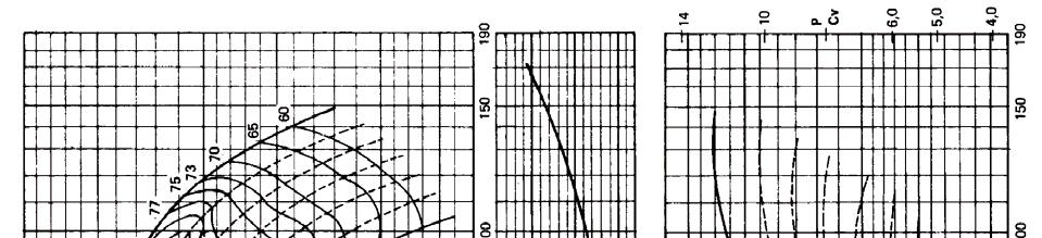
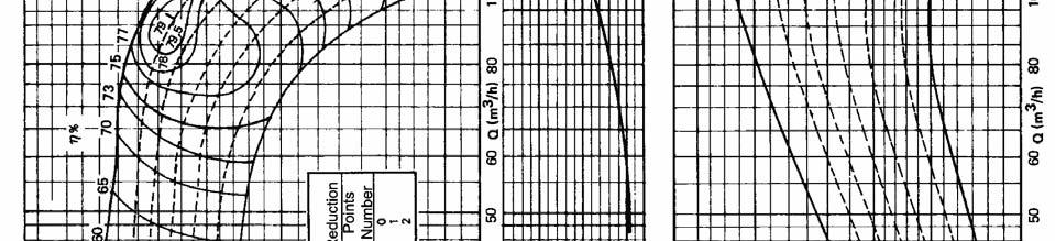
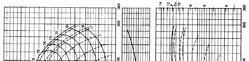
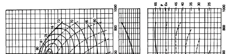
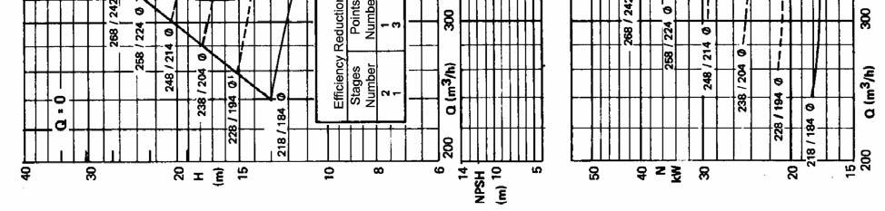
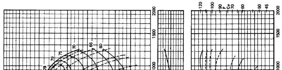
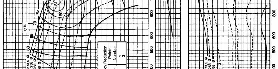
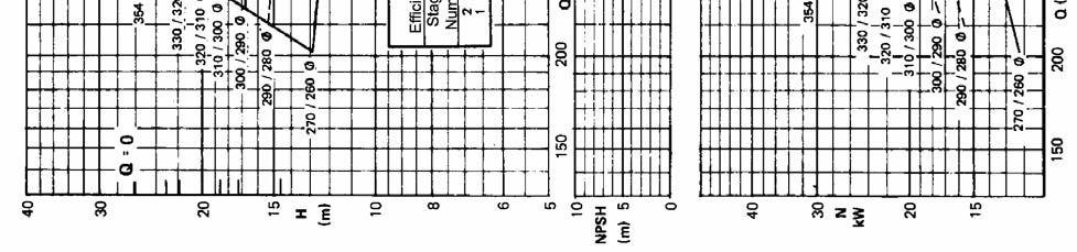
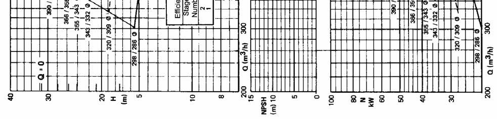
2 5. Selection chart 60 Hz Fig 1 B6B / B7B / B8B n = 3480 rpm Fig 2 B6B up to B16B n = 1740 rpm 2
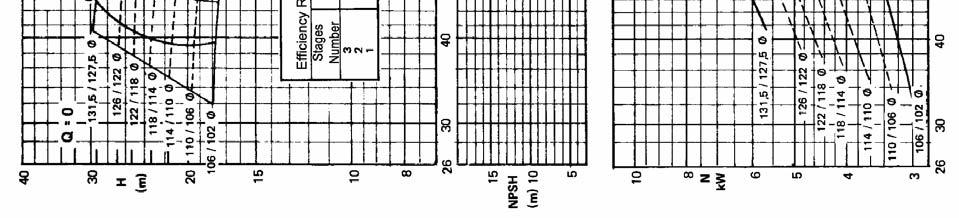
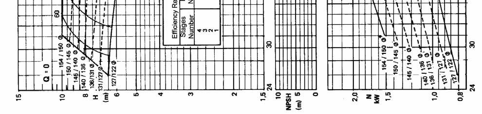
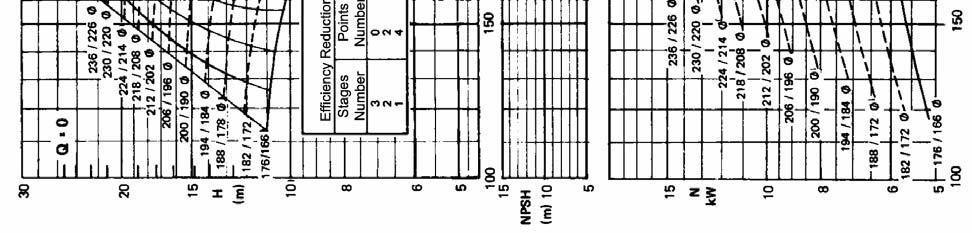
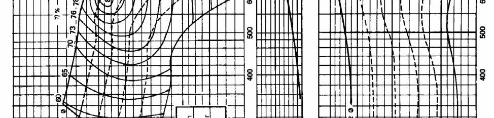
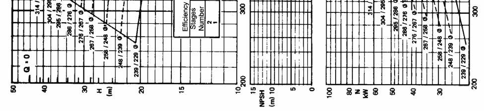
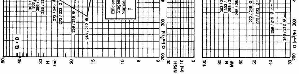
3 Fig 3 B10D up to B18D n = 1740 rpm Fig. 4 B18B up to B24B n= 1160 rpm 3
4 6. Technical Data, Technical data Rotation direction Minimum / maximum flow KSB B Pump size B 6 B B 7 B B 8 B B 10 B B 10 D B 12 B B 12 D B 14 B B 14 D B 16 B B 16 D B 18 B B 18 D B 20 B B 22 B B 24 B Counterclockwise, seen from drive side 0.4 x Qopt / 1.35 x Qopt Maximum suction pressure (Kg/cm 2 ) 10 Maximum discharge pressure for Q=0 (Kg/cm 2 ) Maximum temperature (ºC) 80 Suction case 16 Hydrostatic Test intermediate bowl, Pressure discharge case, 25 (Kg/cm 2 ) column pipe, discharge head Column pipe diameter Column shaft diameter 1 1 3/8 1 3/8 1 1/2 1 1/2 1 1/2 1 1/2 1 1/2 2 3/8 2 3/8 2 3/8 2 3/8 2 3/8 2 3/8 2 3/4" 3 1/8 Intermediate Standard (mm) column pipe 2000 length (mm) Optional (mm) ) top column pipe length(mm) 300 / 600 / / 600 / 900 / 1200 Discharge flange diameter Discharge flange ANSI B 16.5, 150 # R.F Drive with standard solid shaft Thrust bearing 1) BUA 25 BUA35 BUA 45 BUA 60 BUA 75 Drive with hollow shaft Quantity and number of bearings (tanden disposition) 1) Discharge flange diameter Discharge flange standard 2 x BUA x x BUA x x BUA x x BUA x xBUA x Standard: ANSI B 16.1, 125 # F.F Optional: ANSI B 16.1, 250 # F.F Column coupling Threaded Split Maximum stages number Maximum speed (rpm) Maximum ET (m) for discharge nozzle above the floor 3) 4) Maximum ET (m) for discharge nozzle below the floor 4) Pump shaft Maximum P/n Column shaft (HP/rpm) 2) Drive shaft Maximum At the 1200 rpm 1470 Kg 2180 Kg 3120 Kg 3880 Kg 5) 5600Kg 6) thrust bearing speed: 1500 rpm 1360 Kg 2000 Kg 2880 Kg 3620 Kg 5) 5100Kg (Kgf) 6) accepted by 1800 rpm 1250 Kg 1880 Kg 2700 Kg 3400 Kg 5) the thrust bearing 3000 rpm 1080 Kg 1600 Kg (downwards) 3600 rpm 980 Kg 25 ppm lubrication of pump bowl and columns bearings with pumped liquid standard Maximum solid contents 100 ppm lubrication of pump bowl and columns bearings by grease standard lubrication of pump bowl and columns bearings by oil optional lubrication of pump bowl and columns bearings by external source optional Notes: Table 1 1) For applications where pump should start up against an opened discharge valve is required a special thrust bearing dimension. 2) Valid for material SAE For other materials, please consider the following: Material ASTM A 276 T 410 (annealed) ASTM A 276 T 420 (annealed) ASTM A 276 T ASTM A 276 T Conversion Factor 3) In case of 3000 up to 3500 rpm speed, maximum ET is 50m. 4) See ET on page 18. Maximum ET to column shaft and column pipe in steel. For other material, please consult Product Department. 5) For higher axial thrust a segmental pad thrust bearing DS 60 can be used. It admits axial thrust down up to 5800 Kg with 1800 rpm speed. 6) For higher axial thrust a segmental pad thrust bearing DS 80V can be used. It admits axial thrust down up to 8000 Kg with 1800 rpm speed. 7) For 3000 up to 3600 rpm speed, the column pipe length should be 2000 mm. 4

5 7. Description 7.1 Pump Bowl The case parts (suction case, intermediate bowl and discharge case) are vertically split respect to the shaft. The individual case parts are tightened together stud/nut arrangement and sealed by flat gaskets. The suction case has a thread connection for optional suction strainer. Discharge case has flanged connections upon the column set assembly. The impellers are single suction, mixed flow, enclosed and fixed by keys on the pump shaft. Pumps B18B, B20B, B22B and B24B have special 1º stage impeller. The axial hydraulic thrust is taken up through a thrust bearing. Suction case and intermediate bowl are provided with wear rings at the impeller suction side. 7.2 Discharge column Discharge column is composed by intermediate and top column pipe including the following components: Column pipe with flanges at both ends manufactured according to KSB standard; 2 flat gaskets for flanges; column shaft, threaded on both ends; bearing spider; bearing bush; bearing sleeve (not applicable for execution with oil lubrication); shaft enclosing tube (applicable for execution with oil and clean water of external source lubrication) Threaded/split coupling. Attention: The column and top shafts are not protected against the medium. By the use of shaft enclosing tube only those shafts can be protected which lie above the maximum medium level. An adequate corrosion protection is possible only through selection of shaft and coupling material, which is resistant to medium. 8. Bearings and Lubrication 8.1 Thrust bearing The thrust bearing has two angular contact ball bearings in tandem arrangement and one deep groove ball bearing (grease lubricated). Thrust bearing shall be loaded through following components (directed towards suction side): hydraulic axial thrust of the pump. Figs. 5 and 6; weight of dynamic pump bowl parts. Consult Table 2; weight of column shafts and driver (top shaft). Consult Fig. 7; weight of ½ coupling (according to Manufacture's manual). B 22 B Fig 5 Hydraulic axial thrust for Impeller type B. H: Total head at operating point. Pax: Axial thrust 5
. Le = Total column and drive (top) shafts length.")
6 B18 D Fig 6 Hydraulic thrust for Impeller type D. Pump size B 6 B 7 B 8 B 10 B 12 B 14 B 16 B 18 B 20 B 22 B 24 1º stage Each additional stage Table 2 Weight of dynamic pump bowl parts (kg). Le = Total column and drive (top) shafts length. Fig 7 Weight of column and drive shafts including shaft protecting sleeve and column couplings. 6
7 Notes: a) For application with pressures in the suction side (under pressure tank, booster, etc), please consult KSB. b) In hollow shaft drivers (electric motor or angle gear) the axial thrust is supported by the thrust bearing located in the driver. The axial thrust should be calculated as above specification and should be informed to the driver manufacturer during consult and purchase. Instead of ½ coupling weight should be considered the weight of drive/top shaft. c) The thrust bearing up to size BUA75 is cooled by ambient air convection. The DS60 and DS80V thrust bearing have a water cooling chamber(0.3 up to 0.4 m 3 /h) of external source or from the pumped liquid, if it complies with the following criteria: max. inlet temperature: 30ºC max. inlet pressure: 5 kg / cm 2 min. inlet pressure: 1 kg / cm 2 non corrosive clean water For cooling water flow control is supplied a gate valve in the cooling inlet chamber. 8.2 Pump bearing The suction case bearing is made of bronze and grease lubricated with permanent charge. Intermediate bowl bearings are vulcanized and lubricated by pumped liquid. 8.3 Discharge column bearing The discharge column bearing is determined considering the type of lubrication and the following factors: solid contents; contaminate pumped liquid with small quantities of oil or grease allowable; external source liquid availability; prelubrication in column bearing above the minimum level of suction well. STANDARD EXECUTION OPTIONAL Lubrication type Pumped liquid Grease Oil Clean water of external source Column shaft execution Without shaft enclosing tube With shaft enclosing tube 1) Column bearing type Steel / Rubber or elastomer Bronze Bronze Steel / Rubber or elastomer With or without shaft protective sleeve With protective sleeve Without protective sleeve With protective sleeve Notes Column bearings should be prelubricated when the pump has two or more column bearings above the minimum level of suction well. Maximum solid contents for Clean water of external source = 20 ppm. Table 3 1) For size B22B and B24B is available only the execution without shaft enclosing tube and split coupling. 7
8 9. Lubrication 9.1 Pumped liquid lubrication If prelubrication is necessary, it can be done in a tank of approximately 50 liters installed above the top column bearing. The gate valve must be connected between the tank and the column pipes. Before startup, the gate valve must be opened for prelubrication of column bearings. Tank and piping with gate valve can be optionally supplied. 9.2 Grease lubrication A grease pump with electrical motor will be fixed in the drive stool or discharge head. The grease pump has approximately 5 liters in a reservoir and an alarm contact to indicate low quantity of grease. Each column bearing receives a charge of grease separately. The command panel of grease pump electrical motor (normally not supplied by KSB) should be interconnected with main motor panel. If the pump remains in stand by for some days, the grease pump should start up before the electrical motor to guarantee the bearing prelubrication. The size of grease pump, motor power, voltage and supplier is defined by the number of column bearings and grease quantity per bearing. Pump Size B 6 B B 7 B / B 8 B Grease quantity per column bearing g/h 9.3 Oil lubrication B 10 B / B 10 D B 12 B / B 12 D B 14 B B 14 D / B 16 B B 16 D / B 18 B B 18 D / B 20 B B 22 B / B 24 B Table 4 On the drive stool or discharge head is installed a reservoir with approximately 4 liters. Splash lubrication allows the oil quantity adjustment. Between the splash piping and the shaft enclosing tube is connected a solenoid valve that closes the oil charging during the stand by. Connection between solenoid and motor panel should be considered. Voltage of solenoid valve should be defined. Note: Inside pressure in the shaft enclosing tube is not allowable. Therefore the discharge case has a threaded bush with a compensation bore interconnected to the well. 9.4 Clean water of external source lubrication On the drive stool or discharge head is assembled the feeding piping of external source clean water to the shaft enclosing tube. The gate valve, flow control valve and pressure gauge are included in our supply. Before the motor starting be sure that column bearings received external source clean water. 10. Shaft sealing Stuffing box packing is used to seal the shaft at the motor stool or discharge head. The stuffing box packing have 3 up to 5 packing rings assembled in series (depends on the pump size and the lubrication type). The shaft is protected in the sealing area by a shaft protecting sleeve. The oil lubricated or external source clean water have in the top of shaft enclosing pipe an o'ring that avoid oil or external source water leakage. 8
9 11. Drive, coupling and drive stool The following drive methods can be used: STANDARD Drive type Vertical electrical motor with flange solid shaft See fig. 8 Elastic Coupling type Pump axial thrust Drive stool Thrust bearing assembled in the drive stool Steel plate, welded OPTIONAL Vertical electrical motor with flange hollow shaft (special manufacture) By diesel motor through vertical angle gear with hollow shaft flange (special manufacture) 9 rigid 10 Rigid The diesel motor coupling with angle gear should be done with cardan shaft, minimum length of 1.0 m Thrust bearing assembled on the top motor. The motor also has a non reversion ratchet Thrust bearing on the top part of angle gear. The angle gear has a non reversion ratchet Cast iron Cast iron Table 5 Fig. 8 Fig. 9 Fig. 10 Note: For execution with discharge nozzle below the floor, please consult KSB Drive stool VN type or VU type (optional) Fig. 11 Standard Drive stool for V1 motors 9


10 Item No. Designation Item No. Designation Item No. Designation 213 Drive/top shaft 451 Stuffing box housing 900 Screw 320 Angular contact ball bearing 452 Stuffing box gland 901.1/.2 Screw 321 Deep groove ball bearing 461 Stuffing box packing Plug 341 Drive stool / discharge head 507 Thrower 920.8/.9/.11 Lock nut 350 Bearing housing 526 Centering sleeve Bearing nut Bearing cover 636 Grease nipple 924 Adjusting nut Flat gasket 647 Grease feed regulator 931 Lock washer Oring 681 Coupling guard Circlip 422.1/.2 Felt ring Column pipe 11.2 Starting Torque The initial breakaway torque amounts to approximately 15 % from rated moment. In Figure 12 the approximate running at start is shown. I. With open gate valve II. Against closed gate valve Impeller type B III. Against closed gate valve Impeller type D Fig. 12 Starting Torque Curve Torque Md The torque can be calculated with this formula Md = 9549 x P/n, where P = Power requirement at the shaft (motor rating) in kw n = Revolutions of the pump rpm 9549 = Constant 10
11 12. Pump weight The total pump weight is the sum of the following components: pump bowl; column pipe (including bearing spider, column shaft, column coupling, bearing bush, screws and nuts); shaft protecting sleeve, if applicable; Discharge head with or without thrust bearing according the drive type. Pump bowl weight (kg) Pump size B 6 B B 7 B B 8 B B 10 B 12 B 14 B 16 B 18 B/D B/D B/D B/D B/D B 20 B B 22 B B 24 B Stages number Weight of intermediate column pipe set (Kg) length 1500 mm 2000 mm 2500 mm Weight of top column pipe (Kg) length 300 mm 600 mm 900 mm 1200 mm Weight of shaft enclosing tube per meter (Kg/m) Driver with solid shaft Weight of discharge head with thrust bearing Driver with hollow shaft Weight of discharge head without thrust bearing Table Load for foundation Load for foundation is the sum of : pump weight coupling weight driver weight accessories weight pump liquid weight, which will be calculated as following: weight = volume (dm 3 ) x density (kg / dm 3 ). 11
12 Volume = ET (see page 18) + 1m (Discharge head approx. height) multiply by the values on table 7. Pump size Volume (dm 3 ) Table 7 B 6 B B 7 B B 8 B B 10 B B 10 D B 12 B B 12 D B 14 B B 14 D B 16 B B 16 D B 18 B B 18 D B 20 B B 22 B B 24 B Notes: The axial hydraulic thrust is an internal force of motorpump set. The axial hydraulic thrust is not transmitted to the foundations. 14. Assembly height The minimum height of crane hook to assemble and disassemble the pump should be 1.5 time of column pipe or pump bowl height prevailing higher value. 15. Inertia Moment (GD 2 ) GD 2 Total = GD 2 (pump bowl with water) + n x GD 2 (column shaft) + GD 2 (drive/top shaft) + GD 2 (drive coupling ( * ) ) n = column shafts quantity ( * ) according to the manufacturer Pump bowl with water Stages number B 6 B B 7 B B 8 B B 10 B B 10 D B 12 B B 12 D B 14 B B 14 D B 16 B B 16 D B 18 B B 20 B B 22 B B 24 B column shaft length 1500 mm 2000 mm 2500 mm Drive/top shaft Tables 8 GD 2 in Kgm 2 of pump bowl, column shaft and drive / top shaft. B 18 D under consults. 16. Installation Pump power consumption Power reserve for drive motor Up to 30 CV Approximately 20 % Up to 100 CV Approximately 15 % Above 100 CV Approximately 10 % Table 9 Driver power reserve Installation must be always done at the vertical position in wells, reservoirs, rivers, etc. The pumping unit has been designed to suit outdoor installation. The thrust bearings are sealed against the penetration of dust, sand, spray water, etc. The pump stands completely or partially installed in the pumping medium up to the level of 1 st stage impeller. The minimum submergence of the impeller of 1 st stage should correspond to the measurement "B" (minimum submergence). In case there is a suction pipe attached with suction strainer then the water level can fall below the level of 1 st stage impeller. in this case care should be taken that the cavitation does not take place. For this the minimum medium level should be once time of DN over the upper edge of the suction strainer. The minimum submergence is defined by: a) Pump required NPSH. The installation available NPSH should be superior to pump required NPSH. b) Avoid vortex and air suction to guarantee first stage impeller submergence to assure functioning in the pump startup. 12


13 17. Minimum submergence The minimum submergence to guarantee the installation criteria is indicated in the figures below. Fig. 13 Fig. 16 Fig. 14 Fig. 17 Note: DN and t6 see topic 20. Fig. 15 Pump size B 6 B 7 B 8 B 10 B 12 B 14 B 16 B 18 B 20 B 22 B 24 B (mm) Table 10 13
14 2 B B KSB B 18. Discharge head and column pipe friction losses and flow resistance in suction strainer 18.1 Discharge head friction losses. Material: Carbon steel. m/100m Fig.18 Q (m³/h) Note: Table values are to be multiplied by 0.3, for cast iron. 14


15 18.2 Column pipe friction losses without shaft enclosing tube, for set length of 2500 mm Notes: Table values are to be multiplied by 1.1, for set length of 2000 mm. Table values are to be multiplied by 1.2, for set length of 1500 mm. fig Column pipe friction losses with shaft enclosing tube, for set length of 2500 mm Note: Table values are to be multiplied by 1.1, for set length of 1500 mm. fig.20 15

16 18.4 Flow resistance in suction strainer Suction strainer is not part of supply, but can be optionally requested. fig Bearing and stuffing box friction losses 19.1 Bearing friction losses for set length of 2500 mm Note: Table values are to be multiplied by 1.25, for set length of 2000 mm. Table values are to be multiplied by 1.65, for set length of 1500 mm. fig.22 16
 DN d 1 d 2 (pol) d 3 d 4 d 5 t 1 STAGES STD. OPT.")
17 19.2 Stuffing box friction losses 1800 rpm fig.23 Note: For different speeds use the following formula: Pr = Nominal Speed x Pr Dimension tables (in mm) Pump Size t 2 Interm. column pipe length t 3 top column pipe length t 8 (opt.) DN d 1 d 2 (pol) d 3 d 4 d 5 t 1 STAGES STD. OPT B 6 B B 7 B B 8 B B 10 B B 10 D B 12 B B 12 D B 14 B B 14 D B 16 B B 16 D B 18 B B 18 D B 20 B B 22 B B 24 B Table 11 17
18 Pump Size Solid shaft Hollow shaft t 5 t 6 t 7 t 5 t 6 t 7 B 6 B B 7 B B 8 B B 10 B B 10 D B 12 B B 12 D B 14 B B 14 D B 16 B B 16 D B 18 B B 18 D B 20 B B 22 B Under consult B 24 B Note: ET = t 1 + t 2 +t 3 Table 12 18
19 21. Sectional drawings, parts and material list 21.1 Pumped liquid lubricated Fig
20 Part no. Denomination Standard material 106 Suction case A48CL Discharge case A48CL Intermediate bowl Strainer (optional) A48CL30 SAE Pump shaft SAE Column shaft SAE Drive shaft SAE Impeller A48CL Sand guard TM Angular contact ball bearing (see table 1) 321 Deep groove ball bearing (see table 1) 341 Drive stool SAE Bearing housing A48CL Bearing cover A48CL Bearing spider A48CL Flat gasket Hydraulic gasket Sealing ring O ring Copper NB Felt ring Felt 451 Stuffing box housing A48CL Stuffing box gland A48CL Stuffing box packing Aramid & graphite 502 Casing wear ring A48CL Deflector Buna N * 524 Shaft protecting sleeve AISI Spacer sleeve TM Centering sleeve SAE Bearing sleeve AISI Threaded bush TM Bearing bush Steel/NB Cylindrical pin SAE Grease nipple Galvanized steel Grease regulator Coupling guard SAE 1020 SAE Column pipe (see note 2) 743 Suction strainer Brass 801 Flange motor 849 Coupling 852 Threaded coupling AISI Foundation rail SAE Anchor bolt Bolt SAE 1020 SAE Hexagon head bolt SAE Stud Threaded plug SAE 1020 SAE Threaded pin Threaded plug Steel SAE Nut SAE Bearing nut Aço 924 Adjusting nut SAE Lockwasher SAE Circlip Spring steel 940 Key SAE 1045 Note: Other materials under consult SCH 40 ASTM A106GR.A (seamless): For B 18, B 20 and B 24 SAE 1020 (with seam) * AISI 316 for BUA 75 20
21 21.2 Grease lubricated Fig
22 Part no. Denomination Standard material 106 Suction case A48CL Discharge case A48CL Intermediate bowl Strainer (optional) A48CL30 SAE Pump shaft SAE Column shaft SAE Drive shaft SAE Impeller A48CL Sand guard TM Angular contact ball bearing (see table 1) 321 Deep grove ball bearing (see table 1) 341 Drive stool SAE Bearing housing A48CL Bearing cover A48CL Bearing spider A48CL Flat gasket Hydraulic gasket Sealing ring O ring Copper NB Radial seal ring Steel / Rubber 422 Felt ring Felt 451 Stuffing box housing A48CL Stuffing box gland A48CL Lantern ring A48CL Stuffing box packing Aramid & graphite 502 Casing wear ring A48CL Deflector Buna N * 524 Shaft protecting sleeve AISI Spacer sleeve TM Centering sleeve SAE Bearing sleeve AISI Threaded bush TM Bearing bush TM Cylindrical pin SAE Grease pump 636 Grease nipple Galvanized steel Grease regulator Coupling guard SAE 1020 SAE Lubricating pipe Steel 711 Column pipe (see note 2) 720 Conection Steel 743 Suction strainer Brass 801 Flange motor 849 Coupling 852 Threaded coupling AISI Foundation rail SAE Angular support SAE Anchor bolt Bolt SAE 1020 SAE Hexagon head bolt SAE Stud SAE Threaded plug SAE Threaded pin Threaded plug Steel SAE Nut SAE Bearing nut Aço 924 Adjusting nut SAE Lockwasher SAE Circlip Spring steel 940 Key SAE 1045 Notes: Other materials under consult SCH 40 ASTM A106GR.A (seamless): For B 18, B 20 and B 24 SAE 1020 (with seam) * ANSI 316 for BUA 75 22
23 21.3 Oil lubricated (shaft enclosing tube) 21.4 External source water lubricating detail Fig
24 Part no. Denomination Standard material 106 Suction case A48CL Discharge case Strainer (optional) A48CL30 SAE Intermediate bowl A48CL Pump shaft SAE Column shaft SAE Drive shaft SAE Impeller Suction impeller A48CL30 A48CL Sand guard TM Angular contact ball bearing (see table 1) 321 Deep groove ball bearing (see table 1) 341 Drive stool SAE Bearing housing A48CL Bearing cover Bearing part A48CL30 A48CL Bearing spider A48CL Flat gasket Hydraulic gasket Sealing ring Oring Radial seal ring Copper Rubber Steel / Rubber Felt ring Stuffing box cover Feltro A48CL Stuffing box packing Aramid & graphite 502 Casing wear ring A48CL Deflector Buna N * 524 Shaft protecting sleeve AISI Spacer sleeve TM Centering sleeve SAE Threaded bush TM Bearing bush TM Cylindrical pin Rivet SAE 1020 AISI Oil lubricator 636 Grease nipple Galvanized steel 647 Grease regulator SAE Coupling guard SAE Pressostato 710 Lubricating pipe Steel Column pipe Shaft enclosing tube 741 Shut off valve Brass 742 Non return valve Brass 801 Flange motor 849 Coupling 852 Threaded coupling AISI Foundation rail SAE Angular support SAE Anchor bolt SAE Bolt SAE Hexagon head bolt SAE Stud SAE Threaded plug SAE Threaded pin Threaded plug Steel Steel 920 Nut SAE Bearing nut Aço 924 Adjusting nut SAE Lockwasher Circlip Key Plate (see note 2) ASTM A53 GR.B (without seam) SAE 1045 Spring steel SAE 1045 AISI 302 Notes: Other materials under consult SCH 40 ASTM A106GR.A (seamless): For B 18, B 20 and B 24 SAE 1020 (with seam) Applicable only for external source lubrication * AISI 316 for BUA 75 24
25 21.5 Discharge head with hollow shaft motor and without shaft enclosing tube Part no. Denomination Standard material 101 Discharge head A48CL Drive shaft SAE Bearing part A48CL Flat gasket Hydraulic gasket 451 Stuffing box housing A48CL Stuffing box cover A48CL Stuffing box packing Aramid & graphite 524 Shaft protecting sleeve TM Connection Steel 730 Pipe junction Steel 731 Pipe union Steel 743 Valve Brass 803 Hollow shaft motor 901 Hexagon head bolt SAE Stud SAE Threaded plug SAE Nut SAE Adjusting nut SAE Circlip Spring steel 940 Key SAE 1045 NOTE: Other materials under consult Discharge head with hollow shaft motor and with shaft enclosing tube Part no. Denomination Standard material 101 Discharge head A48CL Drive shaft SAE Mancal part A48CL Flat gasket Hydraulic gasket 421 Radial seal ring Steel / rubber 545 Bearing bush TM Cylindrical pin SAE Lubricating pipe Steel 714 Shaft enclosing tube ASTM A 53GR.B (without seam) 731 Pipe union Steel 803 Hollow shaft motor 901 Hexagon head bolt SAE Stud SAE Threaded plug SAE Nut SAE Adjusting nut SAE 1045 NOTE: Other materials under consult Split (muff) coupling for B22B and B24B Part no. Denomination Standard material Split ring Split coupling Threaded pin Stud Nut Key AISI 304 AISI 304 Inox 304 AISI 304 AISI 304 SAE


26 B 6 B 3480 rpm B 7 B NPSH values are measurement values. Please add 0,5 m for safety rpm 26


27 B 8 B 3480 rpm B 6 B NPSH values are measurement values rpm Please add 0,5 m for safety. 27


28 B 7 B 1740 rpm B 8 B NPSH values are measurement values. Please add 0,5 m for safety rpm 28


29 B 10 B 1740 rpm B 10 D NPSH values are measurement values rpm Please add 0,5 m for safety. 29


30 B 12 B 1740 rpm NPSH values are measurement values. B 12 D Please add 0,5 m for safety rpm 30


31 B 14 B 1740 rpm NPSH values are measurement values. B 14D Please add 0,5 m for safety rpm 31


32 B 16 B 1740 rpm NPSH values are measurement values. B 16 D Please add 0,5 m for safety rpm 32


33 B 18 B 1160 rpm B 18 D NPSH values are measurement values. Please add 0,5 m for safety rpm 33


34 B 20 B 1160 rpm B 22 B NPSH values are measurement values rpm Please add 0,5 m for safety. 34


35 B 24 B 1160 rpm NPSH values are measurement values. Please add 0,5 m for safety. 35
36 A3210.0E/ KSB Bombas Hidráulicas SA Rua José Rabello Portella, 400 Várzea Paulista SP Brazil Phone.: Fax: SAK KSB Customer Service Fax:
KSB RPH-V. Process pumps. 3. Designation. 1. Application. 2. Design. 4. Operating Data. to API 610, 11th edition and ISO 13709
 Type Series Booklet 1316.56/04-EN (A1316.0.2E/8) KSB Process pumps to API 610, 11th edition and ISO 13709 1. Application pumps are mainly used in refineries as well as in chemical and petrochemical plants.
BEV. Deep well vertical pumps. 3. Design. 1. Fields of Application. 4. Designation. 2. Operating Data
 Type series booklet CTI-2000/00 [09-2010] BEV Deep well vertical pumps 1. Fields of Application BEV are vertical multistage centrifugal pumps designed for deep well, ditches and tanks to pump clean liquids
KSB HDB. High-pressure centrifugal pump. 1. Application 3. Description. 2. General Description. 4. Operation Data. Technical Booklet A1836.
 Technical Booklet A1836.0EN/0 High-pressure centrifugal pump 1. Application 3. Description The series is recommended for boiler feedwater and power plants, production under pressure at pressure and descaling.
High-pressure pumps Series HP49
 High-pressure pumps Series HP49 www.andritz.com/pumps General Description / Application Multi-stage high pressure pumps for water supply, irrigation and industrial applications, for hot and cold water
Elite. KSB Australia Pty Ltd. Centrifugal Pump
 Type Series Booklet Elite Centrifugal Pump Application The Ajax Elite centrifugal pump is suitable for handling water and similar liquids mainly used in the following applications. -Water Supply -Air conditioning
Axially split volute casing pumps. Applications. Bearings. Shaft seal. Operating data
 Type series booklet 1385.52/3--10 RDLV Axially split volute casing pumps Applications Waterworks, irrigation and drainage pumping stations, power stations, industrial water supply systems, fire fighting
INVCP, INVCN. Vertical pumps for tanks. 3. Design. 1. Fields of Application. 4. Designation. 2. Operating Data
 Type series booklet CTI-0300/03 [05-2012] INVCP, INVCN Vertical pumps for tanks 1. Fields of Application INVCP pumps are used for organic and inorganic liquids in water services and different industries.
PROCESS PUMPS MODEL V200 ANSI B73.2
 EAGLE PROCESS PUMPS V200 ANSI B73.2 POWER END Shaft Diameters Bearings Stuffing Box PUMP END Maximum Diameter Solids Minimum Casing Thickness Casing Corrosion Allowance Working Pressure Test Pressure
RWCP, RWCN. Vertical pumps for tanks for loaded liquids. 1. Fields of Application. 3. Design. 4. Designation. 2. Operating Data
 Type series booklet CTI-4900/01 [04-2012] RWCP, RWCN Vertical pumps for tanks for loaded liquids 1. Fields of Application RWCP and RWCN are vertical, centrifugal pumps designed for wells, ditches and tanks.
NC State University Design and Construction Guidelines Division 23 Hydronic Pumps
 1.0 Purpose A. The following guidelines apply to the selection of pumps primarily for circulating water. It is the goal of NC State to purchase pumps that are selected to provide a long service life, minimal
XFLO XS SERIES. Single Stage Double Suction Split Casing Centrifugal Pump
 XFLO P U M P S XS SERIES Single Stage Double Suction Split Casing Centrifugal Pump General and Construction 1. Applications Waterworks, Irrigation, Drainage pumping stations, Power stations, Industrial
Standard SO according to DIN
 Standard SO according to DIN 24.255 DESIGN FEATURES Design Features Horizontal centrifugal, single Stage pump. Spiral volute casing. Overhung on shaft impeller. Grease or oil lubricated antifriction bearing.
General Service Centrifugal Pump. 3. Designation. 1. Application. 2. Design. 4. Operating Data. Operating Instructions Nº A
 Operating Instructions Nº A2744.8.1E/1 KSB Megabloc General Service Centrifugal Pump Line : Version: Mega Bloc 1. Application The KSB Megabloc pump is designed for pumping clean or turbid liquids and it
RDLO / RDLO V. Axially Split Volute Casing Pumps. Fields of Application. Bearings. Operating Data. Materials. Design. Shaft Seal. Designation 01 P F
 Type Series Booklet 1387.5/2--10 RDLO / RDLO V Axially Split Volute Casing Pumps Fields of Application Waterworks, irrigation and drainage pumping stations, power stations, industrial water supply systems,
Contents. Identification
 Contents Identification Type key Product data Introduction Applications Features and benefits Performance range pole pole Construction Sectional drawing Construction features Test pressure Operating conditions
1100 Series Multi-Stage Vertical Turbine Pumps
 1100 Series Multi-Stage Vertical Turbine Pumps Capacities to 40,000 GPM Heads to 1,500 Feet Temperatures to 200 F Water Lubricated Open Lineshaft Vertical Hollow Shaft Motor The vertical hollow shaft motor
Boiler Feed Booster Pump YNK. Type Series Booklet
 YNK Type Series Booklet Legal information/copyright Type Series Booklet YNK All rights reserved. The contents provided herein must neither be distributed, copied, reproduced, edited or processed for any
Story of 3 R s. Pum pen Intel 1 ligen z
 Story of 3 R s Pum pen Intel 1 ligen z Various Standard for End Suction Pumps Pum pen Intel 2 ligen z Comparison of ET & NL Options ET NL MoC Beyond Cat A & B Yes No MoC Variants within Cat A & B Yes No
MZ, MA. Liquid ring pumps. 3 Design. 1 Fields of application. 4 Designation. 5 Materials. 2 Operating Data
 Type series booklet CTI-1700/00 [12-2008] MZ, MA Liquid ring pumps 1 Fields of application Multi-stage, horizontal liquid ring pumps, with self-priming capacity. MZ and MA pumps are used for pumping of
KSB Megaflow V. Pumps for sewage, effuents and mistures. Mega Submersible / Vertical. 1. Application. 3. Designation. 2. Design. 4.
 Operating Instructions Nº A0..E/ KSB Megaflow V Pumps for sewage, effuents and mistures LINE : TYPE : Mega Submersible / Vertical Impeller type O Impeller type K. Application The KSB Megaflow V centrifugal
Fire Protection. FP-XA End Suction
 Fire Protection FP-XA End Suction PRODUCT BULLETIN MODEL FP-XA END SUCTION CPS Model FP-XA End Suction pumps are used in a variety of fire fighting applications. These rugged and efficient centrifugal
General Service Centrifugal Pump. 1. Application. 3. Designation. 2. Design. 4. Operating Data. Operating Instructions Nº A2744.
 Operating Instructions Nº A2744.8E/2 KSB Megabloc General Service Centrifugal Pump Line : Version: Mega Bloc 1. Application The KSB Megabloc pump is designed for pumping clean or turbid liquids and it
HORIZONTAL MULTI STAGE PUMPS
 HORIZONTAL MULTI STAGE PUMPS APPLICATIONS Water supply Hot/cold water Sprinklers Agriculture Construction Factories Mines Boiler feed Other general high pressure services *Please choose the model, referring
Bearings. Shaft seal. Materials
 Type series booklet 1385.51/3--10 RDL Axially split volute casing pumps Applications Waterworks, irrigation and drainage pumping stations, power stations, industrial water supply systems, fire fighting
Bristol: A History & Future.
 Fire Pumps Bristol: A History & Future. In 1971, seven emirates joined forces to create the United Arab Emirates, with the goal of becoming a growing leader on an international scale. The UAE s focus has
VERTICAL TURBINE PUMP
 21A, Canning Street, Ground Floor, Kolkata 700001, (W.B) India Ph.: (033) 22308125, 39855288, Mob: 09339834915 Fax: (033) 2230 8125, E- mail: powerpointpumps@yahoo.co.in Website: www.powerpointpumps.com
Manufacturing Program: LAND APPLICATIONS. Mixed Flow Pump. type TR
 Mixed Flow Pump type TR Constructional Features Vertical single and multi-stage mixed flow pumps for wet pit installation. Standardised asembly groups: suction, casing, column pipe, discharge bend, rotor
NORTHWESTERN UNIVERSITY PROJECT NAME JOB # ISSUED: 03/29/2017
 SECTION 23 2123 - PUMPS PART 1 - GENERAL 1.1 RELATED DOCUMENTS A. Drawings and general provisions of the Contract, including General and Supplementary Conditions and Division 01 Specification Sections,
Data sheet. Customer item no.: Communication dated: Number: ES Doc. no.: Item no.: 100 Quantity: 1 Date: 19/03/2015 Page: 1 / 6
 Data sheet Item no.: Page: 1 / 6 Operating data Operating data determined for maximum inlet pressure Pumped medium Water Clean water Not containing chemical and mechanical substances which affect the materials
KSB B. Vertical Spindle Well Pumps B
 Operating Instructions A3210.8E/2 KSB B Vertical Spindle Well Pumps B Serial No.: Type series:! These operating instructions contain fundamental information and precautionary notes. Please read the manual
High-pressure pumps Series HP45
 High-pressure pumps Series HP45 www.andritz.com/pumps General Description / Application Multi-stage high pressure pumps for water supply, irrigation and industrial applications, for hot and cold water
General Catalog. A New Vision for Quality Pumps. General Catalog
 General Catalog A New Vision for Quality Pumps General Catalog 2 Tru20 is committed to only the highest quality pumping products. We produce a tremendous range of water and process pumps in order to serve
Basic Hydraulic Features. Basic Mechanical Features
 APRIL 2006 1.0 Overview The ETA is designed for flow rates that fall beyond the range of most end suction pumps. Performance extends to 9,500 GPM, 440 feet of head, and 88% efficiency. This range is covered
Grupa Powen-Wafapomp SA. Pumps for Power and Heat Supplying Industries catalogue
 0 Grupa Powen-Wafapomp SA Pumps for Power and Heat Supplying Industries 2017 catalogue Contents 2 Basic pumps Supply pumps Z YS 4 10 Condensate pumps K i WK 20 Cooling water pumps D P 26 32 Hot water pumps
RDLO / RDLO V Type Series Booklet
 RDL / RDL V Type Series Booklet Legal information/copyright Type Series Booklet RDL / RDL V All rights reserved. The contents provided herein must neither be distributed, copied, reproduced, edited or
Norm-Centrifugal Pumps PN 10
 Norm-Centrifugal Pumps PN 10 Pump dimensions acc. to DIN EN 733 with additional sizes Technical requirements acc. to DIN ISO 9908 Application For pumping pure water, industrial water, sea water, condensate,
RDLO / RDLO V Type Series Booklet
 RDL / RDL V Type Series Booklet Legal information/copyright Type Series Booklet RDL / RDL V All rights reserved. The contents provided herein must neither be distributed, copied, reproduced, edited or
Non-clogging Pump DBS TECHNICAL DATA. Output: up to 1200 m 3 /h
 Non-clogging Pump DBS 3216...30040 TECHNICAL DATA Output: up to 1200 m 3 /h Delivery head: up to 100 m Speed: up to 3600 rpm depending of the pump size and material execution Medium temperature: max. 110
Centrifugal End Suction Fire Pumps
 Centrifugal End Suction Fire Pumps 1 Centrifugal End Suction Fire Pumps Product Overview American-Marsh Model FP-REF End Suction pumps are used in a variety of fire protection services every day. These
Design Characteristics. Aplicaciones
 Design Characteristics Single stage centrifugal. Casing axially split. Double entry impeller. Bearings on both sides of impeller. Suction and discharge branches located in lower casing. Características
G&L Series MPVN. High Pressure Multi-Stage Pumps. Goulds Pumps. ITT Industries
 G&L Series MPVN High Pressure Multi-Stage Pumps www.goulds.com Goulds Pumps ITT Industries A Full Range of Product Features Performance Range: Capacities up to GPM ( m /h) Head up to feet ( m) Maximum
DESIGN FEATURES SPECIAL DESIGN FEATURES. Space Saving. Self Priming. Easy to install. Design Flexibility
 DESIGN FEATURES Space Saving Vertical arrangement saves valuable floor space. Self Prig Designed to operate with submerged impeller. Instantly serviceable. Low operation cost. Easy to install Self- contained
Goulds Small Capacity Double Suction Pump
 Goulds 3410 Small Capacity Double Suction Pump 3410 Double Suction Pumps Designed for a Wide Range of Industrial, Municipal, Capacities to 7,000 GPM (1591 m3/h) Heads to 550 feet (168 m) Temperatures to
Heat Transfer Fluid / Hot Water Pump HPK-L. Type Series Booklet
 Heat Transfer Fluid / Hot Water Pump HPK-L Type Series Booklet Legal information/copyright Type Series Booklet HPK-L All rights reserved. The contents provided herein must neither be distributed, copied,
Application & Reference Data Typical Specifications. Section 914 Vertical Turbine Fire Pump
 Section 914 Page 101 Supersedes Section 913 Page 101 Dated November 1, 199p Application & Reference Data Typical Specifications Section 914 Section 914 Page 102 Supersedes Section 913 Page 102 Dated November
Non-clogging Pump DBS TECHNICAL DATA. Output: up to 1200 m 3 /h. depending of the pump size and material execution
 Non-clogging Pump DBS 3216...30040 TECHNICAL DATA Output: up to 1200 m 3 /h Delivery head: up to 100 m Speed: Medium temperature: max. 110 C Casing pressure: Shaft sealing: up to 3600 rpm depending of
PA SERIES END SUCTION CENTRIFUGAL PUMP SINGLE STAGE BACK PULL-OUT DIN24255 THONG FATT JAYA MACHINERY HARDWARE SDN. BHD.
 END SUCTION CENTRIFUGAL PUMP SINGLE STAGE BACK PULL-OUT DIN24255 50HZ OR 60HZ PA SERIES APPLICATIONS PA Series pumps can be used for the following services in commercial, residential, agriculture, industrial,
480 Series Vertical Turbine Pumps
 480 Series Vertical Turbine Pumps Flows to: 85,000+ GPM Heads to: 2500+ Feet Temperatures to: 400 F Compliance to API 610 Standards Upon Request 140 Years of Pump Manufacturing American-Marsh Pumps, one
High Temperature Air-Cooled Hot Oil Pumps
 Bulletin C 1.4.42 Dean Pump Division High Temperature Air-Cooled Hot Oil Pumps No Water Cooling Required RA3 RA2 DEAN PUMP SERIES RA FAN COOLED HIGH TEMPERATURE HOT OIL PUMPS No Liquid Cooling Required
480 Series Vertical Turbine Pumps
 480 Series Vertical Turbine Pumps Flows to: 300,000 GPM Heads to: 1400+ Feet Temperatures to: 400 F Compliance to API 610 Standards Upon Request 130 Years of Pump Manufacturing American-Marsh Pumps, one
Data sheet. Omega B GB G F Version no.: 1. Operating data. Design. Driver, accessories. Clean water. Actual developed head 57.
 Data sheet Item no.: 3700 Page: 1 / 5 Operating data Pumped medium Water Actual flow rate 415.38 m ³/h Clean water Actual developed head 57.81 m Not containing chemical and Efficiency 82.3 % mechanical
F-Series Fire Fighting Pumps
 F-Series Fire Fighting Pumps VISION To be a leading local manufacturer and reliable partner providing engineered products and solutions to our customers. MISSION Supporting the socio-economic development
Contents Project: Model: Chk d: Date:
 Contents Model DSHU6. DSHU6.7 DSHU6. DSU6. DSHU6. DSU6.7 DSHU6.7 8DSU6. 8DSHU6. 8DSU6.7 8DSHU6.7 DSU6. DSU67. Section Page Specifications -7, 8 Selection Chart -7., 8. Performance Curves -6 Outline Drawings
University of Houston Master Construction Specifications Insert Project Name
 SECTION 23 30 00 - HVAC PUMPS PART 1 - GENERAL 1.1 RELATED DOCUMENTS: A. The Conditions of the Contract and applicable requirements of Division 1, "General Requirements", and Section 23 01 00, "Mechanical
SUGGESTED SPECIFICATIONS
 PART 1 - GENERAL 1.01 SCOPE A. Pumps to be supplied under this specification shall be of a severe duty, recessed cupped impeller design suitable for use in (SLUDGE, GRIT, ETC. APPLICATIONS) with a 20 year
Ductile Iron, Jacketed Pumps: Catalog Section 1602 Cast Iron, Non-Jacketed Pumps: Catalog Section 1401 HL4126A
 Page 1601.1 TABLE OF CONTENTS Features & Benefits...2 Port Location Options...2 Model Number Key...3 Standard Materials of Construction...3 Cutaway View & Pump Features...4 Special Materials & Options
High Temperature Air-Cooled Hot Oil Pumps
 Bulletin C 1.4.42 Dean Pump Division High Temperature Air-Cooled Hot Oil Pumps No Water Cooling Required RA296 RA3146 RA3186 RA296 The smaller, foot mounted economy version of the air-cooled RA series
SMN Double-Suction Axially Split Pump
 SMN Double-Suction xially Split Pump motralec 4 rue Lavoisier. Z Lavoisier. 95223 HERBLY CEDEX Tel. : 01.39.97.65.10 / Fax. : 01.39.97.68.48 Demande de prix / e-mail : service-commercial@motralec.com www.motralec.com
TECHNICAL BROCHURE BMPVN MPVN HIGH PRESSURE MULTI-STAGE PUMPS
 TECHNICAL BROCHURE BMPVN MPVN HIGH PRESSURE MULTI-STAGE PUMPS A FULL RANGE OF PRODUCT FEATURES Performance Range: Capacities up to GPM ( m /h) Head up to feet ( m) Maximum speed up to RPM Sizes: From "
Model 3550 ASME/ANSI B73.1M Industrial Process Pumps
 3500 Series Model 3550 ASME/ANSI B73.1M Industrial Process Pumps The Aurora Model 3550 was designed to perform in the toughest industrial applications whether in the chemical, petro-chemical, mining, pulp
CVFV Vertical multistage low pressure pumps
 CVFV Vertical multistage lowpressure pumps VERTICAL MULTISTAGE LOWPRESSURE PUMPS CVFV Application Vertical pumps CVFV are intended for pumping drinking and service water or even slightly polluted or turbid
855 Filtrate Pump, Close Coupled and Overhead Mounted Pumps
 855 Filtrate Pump, Close Coupled and Overhead Mounted Pumps Technical Specification Pages This page left intentionally blank. 1.0 Overview. The 855 Series is Carver s offering specifically designed to
General. Shaft Seal. Nozzle Orientations. Field of Application. Design. Drive. Bearings. Product Catalogue
 Product Catalogue ETA C and D General The well-known ETA-pump on the bearing bracket C and D is constructed in accordance with DIN 24 255 standard and completes the performance range up to max. 100 m3/hr
Discharge diameters 1.5", 2", 3", 4", 5", 6", 8", 10", 12" & 14" HP 1 to 500. Split Coupled Vertical In-Line Pumps BVL
 Discharge diameters 1.5", 2", 3", 4", 5", 6", 8", 10", 12" & 14" HP 1 to 500 Split Coupled Vertical In-Line Pumps BVL Split Coupled Vertical In-Line Pumps Capacities up to 12,000 GPM Heads up to 560 ft
INSTALLATION, OPERATION AND MAINTENANCE INSTRUCTIONS
 INSTALLATION, OPERATION AND MAINTENANCE INSTRUCTIONS Contents Section 1. General Observations... 2 2. Operation... 4 3. Control During Operation... 5 4. Trouble Shooting... 6 5. Maintenance... 7 Please
PWA-IL B73.2 IN-LINE
 PWA-IL ANSI/ASME B73.2 IN-LINE PROCESS PUMP PWA-IL ANSI/ASME B73.2 IN-LINE PROCESS PUMP COMPETITIVE ADVANTAGES vs. Ductile Iron n High-strength, impact resistant liquid ends for improved durability and
UNIVERSAL PRODUCT LINE: DUCTILE IRON JACKETED PUMPS TABLE OF CONTENTS SERIES DESCRIPTION RELATED PRODUCTS OPERATING RANGE
 Page 1602.1 TABLE OF CONTENTS Features & Benefits...2 Porting & Sealing...2 Jacketing...2 Revolvable Pump Casings...2 Cutaway View & Pump Features...3 Model Number Key...4 Standard Materials of Construction...4
Jansen Pompentechniek T: +31(0) E:
 E:") 1 1 VOGEL - Pumps with Channel Type Impeller, Design KS Capacity up to 500 m 3 /h (2200 USgpm) Head up to 45 m (150 feet) Speed up to 1450 min -1 (1450 r.p.m.) Sizes: DN 65 up to DN 150 (21/2 up to 6 )
1 1 VOGEL - Pumps with Channel Type Impeller, Design KS Capacity up to 500 m 3 /h (2200 USgpm) Head up to 45 m (150 feet) Speed up to 1450 min -1 (1450 r.p.m.) Sizes: DN 65 up to DN 150 (21/2 up to 6 )
Side channel pumps PN 16 SOH - SOHB - SOHM. Self-priming centrifugal pumps. Technical description
 Side channel pumps PN 16 Self-priming centrifugal pumps SOH - SOHB - SOHM Technical description ATEX certified The SOH side channel pump models are available in a variety of designs. Design base plate
N N O V A T I O N E F F I C I E N C Y Q U A L I T Y JTN. Heavy Duty, Multi-Stage, API 610 Process Pump
 N N O V A T I O N E F F I C I E N C Y Q U A L I T Y JTN For more than 60 years the name Ruhrpumpen has been synonymous worldwide with innovation and reliability for pumping technology Ruhrpumpen is an
High Temperature Chemical Process Inline Pumps
 Bulletin C-1.2.21. Dean Pump Division High Temperature Chemical Process Inline Pumps Series DL Series DL High Temperature Chemical Process Inline Pumps Capacities to 6 GPM (182 m 3 /hr) Heads to feet (167
UNIVERSAL PRODUCT LINE: STEEL EXTERNALS JACKETED PUMPS TABLE OF CONTENTS SERIES DESCRIPTION RELATED PRODUCTS OPERATING RANGE
 SERIES 223A, 4223A, 323A, 4323A Page 1302.1 Issue B TABLE OF CONTENTS Features & Benefits...2 Jacketing...2 Relief Valve Configurations...3 Porting & Sealing...3 Revolvable Pump Casings...3 Cutaway View
PWM API 610 BB3 Multistage Pump
 PWM API 610 BB Multistage Pump PWM API 610 BB MULTISTAGE PUMP HYDRAULIC PERFORMANCE COVERAGE 60 Hz Performance Coverage FLOW (m /h) Visit our web site at www.pumpworks610.com and specify flow and performance
Page - CONSTRUCTIONS 300 SECTIONAL VIEW DRAWING 300 SECTIONAL VIEW TABLE DIMENSIONS AND WEIGHT 400 PUMP DRAWING 400 DIMENSION PUMP TABLE 401
 CONTENTS Page - SPECIFICATIONS 200 SELECTION CHART 201 TYPE KEY AND CURVE SPECIFICATIONS 203 PERFORMANCE CURVE R10 205 PERFORMANCE CURVE R13 206 PERFORMANCE CURVE S25 207 PERFORMANCE CURVE S32 208 PERFORMANCE
PWH API 610 SINGLE STAGE OH2
 PWH API 610 SINGLE STAGE OH2 PWH API 610 PROCESS PUMP HYDRAULIC PERFORMANCE COVERAGE 60 Hz Performance Coverage Visit our web site at www.pumpworks610.com and specify flow and performance needs and obtain
Volute Casing Pump additional sizes to those of ISO 2858/EN 22858
 Volute Casing Pump additional sizes to those of ISO 2858/EN 22858 CBTA 150200...350400 + 2 additional sizes 100160 and 125200 TECHNICAL DATA Output: up to 2200 m 3 /h Delivery head: up to 160 m Speed:
N N O V A T I O N E F F I C I E N C Y Q U A L I T Y JTN. Heavy Duty, Multi-Stage, API 610 Process Pump
 N N O V A T I O N E F F I C I E N C Y Q U A L I T Y JTN For more than 60 years the name Ruhrpumpen has been synonymous worldwide with innovation and reliability for pumping technology Ruhrpumpen is an
Waste Water, Condensate and Heat Transfer Fluid Pump. Type Series Booklet
 Waste Water, Condensate and Heat Transfer Fluid Pump Type Series Booklet Legal information/copyright Type Series Booklet All rights reserved. The contents provided herein must neither be distributed, copied,
Multistage Pumps MP, MPA, MPB, MPV SIZES DN 40 - DN 125. Jansen Pompentechniek T: +31(0) E:
 E:") Multistage Pumps MP, MPA, MPB, MPV SIZES DN 40 - DN 125 Technical Data Performance range: m Capacities up to 340m 3 /h (1500USgpm) m Head up to 500m (1640feet) m Max. speed up to 3600rpm Multistage pumps
Multistage Pumps MP, MPA, MPB, MPV SIZES DN 40 - DN 125 Technical Data Performance range: m Capacities up to 340m 3 /h (1500USgpm) m Head up to 500m (1640feet) m Max. speed up to 3600rpm Multistage pumps
CRANE-DEMING VERTICAL IN-LINE INDUSTRIAL BULLETIN 3180 SECTION 38
 CRANE-DEMING VERTICAL IN-LINE INDUSTRIAL BULLETIN 3180 SECTION 38 1 ease of installation & maintenance Install like a valve Mount in the pipeline Support on pipe or foundation... Save space - save time
Bulletin C Dean Pump Division. Heavy Duty, High Temperature Process Pumps. R4140 Telescoping Guard. R4140 C-Face Motor Support
 Bulletin C 1.4.43 Dean Pump Division Heavy Duty, High Temperature Process Pumps R4140 Telescoping Guard R4140 C-Face Motor Support Dean Pump Series R Centrifugal Process Pumps Capacities to 5000 GPM (1135
KWP non-clogging centrifugal pump. Designation
 Type series booklet.5/80 G KWP KWP nonclogging centrifugal pump Automation products available: PumpEpert Hyamaster hyatronic Fields of Application For handling all kinds of pulps not liable to plait, as
PWM. API 610 BB3 Multistage Pump
 PWM API 610 BB3 Multistage Pump HYDRAULIC PERFORMANCE COVERAGE FLOW (m 3 /h) 60 Hz Performance Coverage Visit our web site at www.pumpworks610.com and specify flow and performance needs and obtain pump
KIRLOSKAR ROMAK PUMP - RMK ISO 2858 / DIN EN / ISO 5199
 KIRLOSKAR ROMAK PUMP - RMK ISO 2858 / DIN EN 22858 / ISO 5199 MAGNETIC DRIVE PUMP TYPE - RMK RANGE Discharge capacity (Q) : 3 Up to 300 m /hr Delivery head (H) : Up to 150 m (at 2900 rpm) Available nominal
Bulletin BX-512H. Bell & Gossett. Series HSC-S Pumps Technical Bulletin. Bell & Gossett. Part of the. Equipment Selection Programs
 Bulletin BX-1H Bell & Gossett Series HSC-S Pumps Technical Bulletin Part of the Bell & Gossett Equipment Selection Programs TABLE OF CONTENTS Useful Pump Formulas...............................................
G2C and G2S Series Vertical Cantilever and Sump Pumps
 G2C and G2S Series s Technical Specification Pages This page left intentionally blank. 1.0 Overview. Carver s vertical pump line is designed for moderate to high flow rates. It includes a cantilevered
Side channel pumps ADH/CDH AEH TECHNICAL DATA. Temperature: max. 120 C. PN 40 for AEH
 Side channel pumps ADH/CDH 0801... 2504 AEH 0805... 0808 TECHNICAL DATA Capacity: Head: Speed: max. 7,2 m³/h max. 400 m max. 3000 rpm Temperature: max. 120 C Casing pressure: Shaft sealing: PN 25 for ADH/CDH
Goulds 3181 High-temperature/Pressure Paper Stock/ Process Pumps
 High-temperature/Pressure Paper Stock/ Process Pumps Designed to Handle High Temperature and High Pressure Services of the Pulp & Paper Industries Capacities to 13,000 GPM (3000 m 3 /h) Heads to 410 feet
3312 Model. pumping Model Model AURORA Series HORIZONTAL AND VERTICAL CLOSE-COUPLED PUMPS
 3312 Model pumping 3314 Model 3311 Model AURORA 3310 Series HORIZONTAL AND VERTICAL CLOSE-COUPLED PUMPS WWW.AURORAPUMP.COM AURORA 3310 Series Horizontal and Vertical Close-Coupled Pumps Capacities to 3800
4500C Series Vortex Pumps
 Section 009 Page 003 4500C Series Vortex Pumps Table of Contents 4500C Performance 2" x 2" - 4523C, Multiple Speed... 004 3" x 3" - 4523C, Multiple Speed... 004 4" x 4" - 4522C, Multiple Speed... 005 4"
EBARA Submersible Propeller Pumps Contents Project: Model: Chk d: Date: Model
 Contents Model A0553 C1125 V0494 A0713 C1285 V0554 A0843 C1455 V0754 A03 C15 V0854 C1915 V0974 C2185 V1154 C2905 Section Page Specifications 3-3 Model Designation 3-6 Impeller Data 3-8 Material Specifications
Volute Casing Centrifugal Pumps PN 16 for heat-transfer liquids Heat-transfer oil up to 350 C Hot water up to183 C
 Volute Casing Centrifugal Pumps PN 16 for heat-transfer liquids Heat-transfer oil up to 350 C Hot water up to183 C Series CMIT in inline design Series CMAT with axial inlet ATEX 0 a Series CMAT Series
Data sheet. Page: 1 / 5 ETN GG A 11GA201502B. Operating data. Design. Requested developed head m. Efficiency 74.
 Data sheet Page: 1 / 5 Operating data Requested flow rate 160.00 m³/h Actual flow rate 159.85 m³/h Operating data determined for maximum inlet pressure Actual developed head 20.96 m Requested developed
EN. 850 Filtrate Pumps. Technical Specification Pages
 850 17.01.EN 850 Filtrate Pumps Technical Specification Pages 850 Series Filtrate Pump 850 17.01.EN This page left intentionally blank. 1.0 Overview. The 850 is Carver s filtrate pump line designed for
Vertical multistage centrifugal pumps in ring-section design
 Vertical multistage centrifugal pumps in ring-section design Vertical multistage centrifugal pumps in ring-section design PUMP DESIGN Multistage centrifugal pumps in ring-section design, radially split,
G&L Pumps. TECHNICAL Brochure BAC8100. Series A-C 8100 SPLIT CASE PUMPS
 TECHNICAL Brochure BAC8 Series A-C 8 SPLIT CASE PUMPS TABLE OF CONTENTS Useful Pump Formulas 2 Performance Curves 3-5 Materials of Construction (Standard) 6 Materials of Construction (Optional) 7 Pump
IDROCHEMICAL CENTRIFUGAL PUMPS FOR CHEMICAL SERVICE ACCORDING TO ISO 2858 STANDARDS
 IDROCHEMICAL CENTRIFUGAL PUMPS AND MIXERS NCM Line CENTRIFUGAL PUMPS FOR CHEMICAL SERVICE ACCORDING TO ISO 2858 STANDARDS GENERAL FEATURES The Idrochemical NCM process pumps conform to ISO 2858 dimensional
Technical data 50 & 60 Hz. Vertical centrifugal pumps Series: DPLHS
 Technical data 50 & 60 Hz Vertical centrifugal pumps Series: DPLHS 2 Table of Contents 1 Pump introduction 1.1 General... 4 1.2 Model key... 4 1.3 Description of the product... 4 1.4 Operation... 5 1.5
TKL. Hydro-Titan Heavy Duty Back Pull-out Water & Process Liquid Pump. Experience In Motion
 TKL Hydro-Titan Heavy Duty Back Pull-out Water & Process Liquid Pump Experience In Motion 1 The total cost of a pump includes not only purchase price, but cost of operation: power costs, reliability, ease
UNIVERSAL PRODUCT LINE: CAST IRON NON-JACKETED PUMPS SERIES DESCRIPTION TABLE OF CONTENTS RELATED PRODUCTS OPERATING RANGE:
 Page 1401.1 TABLE OF CONTENTS Features & Benefits...2 Port Location Options...2 Model Number Key...3 Standard Materials of Construction...3 Cutaway View & Pump Features (124A/AE, 4124A/AE, 324A, 4324A)...4