DEHA SPHERICAL HEAD LIFTING ANCHOR SYSTEM KKT 13-E
|
|
|
- Tyler Wheeler
- 6 years ago
- Views:
Transcription


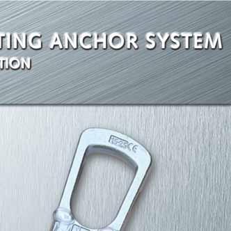
1 KKT 13-E CONCRETE Tis catalogue is an installation and application instruction as defined in VDI/BV-BS 6205


2 Introduction Certified quality from HALFEN Connect to safety. VDI/BV-BS 6205 HALFEN Sperical ead ancors meet te requirements of te European macine guideline (MD) 2006/42/EC. Te required steel load capacity for transport systems is defined in tese guidelines. To also ensure safe use of transport ancor systems wit te required resistance values for cast-in ancors, HALFEN Transport ancor and transport ancor systems also meet te requirements of VDI/BV-BS regulation HALFEN - dependability ig ductility ig performance even in extreme situations Te regulation titled Transport ancor and Transport ancor systems for precast concrete elements represents up-to-date tecnological knowledge in tis field. HALFEN ensures a constant ig standard of safety for its transport ancors and systems by complying wit te requirements set in tese regulations. To confirm conformity wit MD 2006/42/EC in conjunction wit te VDI/BV-BS 6205 all HALFEN Transport ancor systems are CE marked. Tis catalogue is an installation and application instruction as defined in VDI/BV-BS 6205 increased dependable cold-tougness same caracteristics irrespective of environmental conditions To guarantee a ig level of safety all HALFEN ancors and ancor systems are subjected to regular self- and tird-party quality control. Te quality control system is based on te quality and test requirements stipulated by te RAL association for ancoring and reinforcement tecnology. Compliance wit tese stringent test and monitoring requirements is confirmed wit te RAL mark. By applying te CE mark in combination wit te RAL mark we guarantee continuous ig quality and maximal safety for your company, your employees and for your customers. quality control safety in application Foto: coresince / Quelle: Potocase Foto: Elsabe / Quelle: Potocase Specially tempered steel guarantees extensive elastic and plastic properties. Te required unique steel compositions to acieve product caracteristics are specified by HALFEN. Numerous tests and many years of experience guarantee best possible results and te igest safety in all applications. Te special composition of te steel ensures constant identical caracteristics (temperature independent). Steel used by HALFEN exceeds te requirment of DIN EN By specifying products and material, continual raw material, product monitoring and testing by renown independent bodies and universities, our customers are assured tat te quality and properties of all HALFEN Ancors remain consistent. 2

3 Contents Introduction - Product information 2 - System overview 4 - Scope of delivery 6 - Installation and application 10 13, Design calculations 14 Transport ancor - Sperical ead ancor for beams and walls 18 - Sperical ead ancor for slabs 24 - Sperical ead rod ancor 26 - Offset sperical ead rod ancor and sperical ead ancor 28 - Sperical ead eye ancor 30 - Double-eaded - transport ancor 31 - Quick fitting sperical ead ancor DSM 32 - Sperical ead pitcing (tilting) ancor 34 - Sperical ead slab ancor 36 Recess formers - recess fillers and accessories - Installation 37 - Recess formers (rubber and steel) 38 - Recess fillers 42 - Accessories 43 Lifting links - DEHA Universal ead-link 46 - DEHA Small universal ead-link 48 DEHA Transport ancor systems - System for use in utility-pipe projects 50 - System used in tunnel construction 51 3
4 System-Overview DEHA Sperical ead ancors Sperical ead ancor Standard version Sperical ead rod ancor Standard version D Narrow foot sperical ead ancor D Applications Columns, beams, slabs, walls, panels, pipes Tin walls, prefabricated brick-faced walls Prestressed beams wit minimal tickness Features Element tickness, concrete compressive strengt, reinforcement Element tickness, concrete compressive strengt, reinforcement Offset sperical ead ancor Offset sperical rod ancor Element tickness, concrete compressive strengt, reinforcement DSM Quick fitting sperical ead ancor Applications Sandwic panels Tin sandwic panels Features Element tickness, concrete compressive strengt, reinforcement Element tickness, concrete compressive strengt, reinforcement Precast elements wit restricted access ancor positions Element tickness, concrete compressive strengt, reinforcement Sperical ead eye ancor Sperical ead plate ancor Sperical ead pitcing ancor Applications Features Prestressed beams; tin-wall elements; low concrete strengt Element tickness, concrete compressive strengt, reinforcement Large tin slabs wit ig weigt, prefab garages Element tickness, concrete compressive strengt, reinforcement Lifting links Tin panels tat are lifted at 90 from te formwork Element tickness, concrete compressive strengt, reinforcement Universal ead lifting link Small universal ead lifting link Applications Lifting device for all types of sperical ead ancors in load es Lifting device for all types of sperical ead ancors in load es
5 System-Overview Recess formers and recess void fillers, accessories Rubber recess former, round Rubber recess former, narrow Rubber recess former, round, for Sperical ead pitcing ancor For all ancors except tilt-up ancors For all ancors except tilt-up ancors Applications Only for tilt-up ancors and DSM and DSM Higly durable and good Suitable for smaller recesses in Special adapter facilitates use of te Features resistance against formwork oil very tin wall panels. universal ead lifting link Polyuretane recess former for DSM Magnetic recess former for DSM Rubber recess former for DSM Applications For quick fitting lifting ancor DSM For quick fitting lifting ancor DSM For quick fitting lifting ancor DSM Features Higly durable and form stability Magnetic Higly durable and good resistance against formwork oil Steel recess former, round Magnetic steel recess former, round Trumpet steel recess former M 6152 Applications Installed wit rubber grommet Installed wit rubber grommet Installed wit rubber grommet For all ancors except tilt-up ancors and DSM For all ancors except tilt-up ancors and DSM Features Higly durable Magnetic, igly durable Higly durable For all ancors except tilt-up ancors and DSM Magnetic trumpet steel recess former Recess void filler, Polystyrene Fibre reinforce concrete recess void filler 6152 M 6015 VKF 6172 Installed wit rubber grommet Applications For all ancors except tilt-up ancors Used to protect te recess and DSM from dirt, water and ice To permamently seal recesses in concrete Features Magnetic, igly durable Wit appropiate aesive watertigt up to 5 bar
6 Selection Tables - Ancors Sperical ead ancor: load Sperical ead ancor: load mill finis ot-dipped galvanised , , FV , , FV , , FV , , FV , , FV , , FV , , FV , , FV , , FV , , FV , , FV , , FV , , FV , , FV , , FV , , FV , , FV , , FV , , FV , , FV , , FV , , FV , , FV , , FV , , , FV , , FV , , FV , , FV , on request , , FV , , FV , , FV , , FV , , FV , , FV Items marked wit ( ) can be found in te load carts. mill finis ot-dipped galvanised , , FV , , FV , , FV , , FV , , FV , , FV , , FV , , FV , , FV , , FV , , FV , , FV , , FV , , FV , , FV , , FV , , FV , , FV , , FV , , FV , , FV , , FV , on request , , FV , , FV , , FV , , FV , , FV , , FV , , FV , , FV , , FV , , FV , , FV , not available , not available Stainless steel , A , A , A , A , A , A , A , A Oter lengts and load es up to 40.0 on request. Minimum orders and delivery times on request 6
7 Selection Tables - Ancors DEHA Sperical ead rod ancor DEHA Sperical ead ancor, offset version mill finis ot-dipped galvanised , , FV , , FV , , FV , , FV , , FV , , FV , , FV , , FV , , FV , , FV mill finis ot-dipped galvanised , , FV , , FV , , FV , , FV , , FV , , FV , , FV , , FV DEHA Sperical ead plate ancor DEHA Sperical ead rod ancor, offset version mill finis ot-dipped galvanised , , FV , , FV , , FV , , , FV DEHA Double-eaded - transport ancor mill finis ot-dipped galvanised , , FV , , FV , , FV , , FV , , FV , , FV , , FV DEHA Sperical ead pitcing (tilting) ancor 500 D mill finis ot-dipped galvanised ,0-0340D ,0-0340D FV ,0-0400D ,0-0400D FV ,0-0500D ,0-0500D FV ,0-0700D ,0-0700D FV mill finis ot-dipped galvanised , , FV , , FV DEHA Quick fitting sperical ead ancor (DSM) DEHA Sperical ead eye ancor mill finis ot-dipped galvanised mill finis ot-dipped galvanised , , FV , , FV , , FV , , FV , , FV , , FV , , FV , , FV , , FV , , FV , , FV , , , FV
8 Selection Tables - Recess Formers Rubber recess formers Hemisperical sape Narrow incl. plate wit treaded rod incl. plate wit socket witout steel parts incl. plate wit treaded rod incl. plate wit socket witout steel parts Article Article Article Article Article Article , , , , , , , , , , , , , , , , , , , , , , , , , , , , , , , , , , , , , , , , , , , , , , , , Recess formers Recess void filler For sperical ead pitcing ancor Rubber, round Polyuretane For quick fitting sperical ead ancor DSM Polyuretane wit magnet Rubber Polystyrene Fibre-reinforced ligtweigt concrete Article Article Article Article Article Article , , , , , , , , , , , , , , , , , ,
9 Selection Tables - Recess formers - Lifting Links DEHA Steel recess formers Round Trumpet sape Round wit magnet Trumpet saped wit magnet DEHA Lifting Links Universal ead lifting link UKK Small universal ead lifting link Article Article Article Article Article Article , , ,3 M ,3 M , , , , ,5 M ,5 M , , , , ,0 M ,0 M , , ,0 M , , , , , Accessories for DEHA Recess former Rubber grommet Double rubber grommet Pitcing plate Plate wit treaded rod and wing nut Plate wit socket Treaded rod wit wing nut Article Article Article Article Article Article , ,3 D , , , S , ,5 D , , ,0 D , , ,5 D , , , , , , , , ,0 0737, S S
10 Installation and Application Safety regulations Identification Installation and application Te transport ancor system is made up of te permanently cast-in transport ancor and te temporarily connected lifting equipment. Te basic principles for dimensioning and application of transport ancors can be found in te VDI/BV-BS guidelines Te metods in te guidelines represent current tecnology. Te regulations require te following safety factors: Failure safety factors Steel failure of ancors: = 3.0 Concrete failure*: = 2.5 Failure in te lifting-link: = 4.0 * A safety factor of = 2.1 can be assumed for transport ancors installed in a continuous supervised factory environment. For safety reasons, te installation and application instructions for DEHA Lifting systems must always be available at te place of use. Te installation and application instructions must be readily available on site, in te precast plant or on te construction site. Te plant or site manager must ensure tat te operator as read and understood te installation and application instructions for tis system. All DEHA Lifting and oisting equipment are clearly and visible marked. According to (VDI/BV-BS Rictlinie 6205 safety regulations for lifting ancors and systems, identification marking of all lifting elements must remain clearly visible, even after installation. Sperical-ead transport ancor 6000, Sperical ead plate ancor 6010, Sperical-ead rod ancor Sperical-ead rod-ancor 6050, Offset sperical ead rod ancor 6052, Quick fitting sperical ead ancor 6073 Sperical-ead-eye-ancor 6001 Sperical-ead-Pitcing 6006 Te following tecnical specifications and requirements must be observed wen installing DEHA Sperical ead transport-ancor systems. Transport ancors wic are incorrectly installed, defective or damaged (for example corrosion damage or wit visible deformities) must not be used for lifting. Stainless steel transport ancors Transport ancors may not be used repeatedly. Multiple lifting in te normal sequence of transporting and loading, troug to final erection is not defined as repeated use. Transport ancors for permanent use in crane ballast etc. must be made of stainless steel in accordance wit te approval regulation; approval no. Z Quality control All transport ancors and systems are quality controlled in accordance wit DIN EN ISO 9001 and in accordance wit te Quality Assurance and Test Specifications of te German certifier RAL Gütegemeinscaft Verankerungsund Bewerungstecnik e.v.. (RAL Quality association for ancorage and reinforcement tecnology) Transport-ancor lengt CE-Mark Manufacturer DH Abbr. for DEHA Damaged ancor Defective or damaged ancors (for example corrosion damage) must not be used for lifting. Te ancor may not be used if tere is damage to te concrete wic may reduce te load capacity. 10
11 Installation and Application Criteria for ancor selection Maximum load capacities, edge distances and installation values can be found in te respective tables. Irrespective of te selected ancortype (selected according to te load acting on te ancor) te following factors must be taken into account for calculation: weigt of precast element of ancors ancor layout of load bearing ancors spread angle in te oist ancor diagonal pull properties dynamic loads adesion to te formwork Ensure sufficient reinforcement if slabs are cast in te orizontal and subsequently lifted uprigt witout a tilting-table. Number of ancors Te of ancors determines te type of oist tat needs to be used. A oist wit more tan two cables is statically indeterminate if te ancors are aligned along a single axis. Hoists wit more tan tree cables are deemed statically indeterminate if measures are not taken to ensure te load is distributed amongst all ancors (for example; wit a spreader beam etc.). Installation and application DEHA Sperical ead lifting ancor systems sould only be installed wen te following tecnical specifications and requirements ave been met: load capacity edge spacing concrete grade load direction additional reinforcement capacity Te load capacity of te ancor depends on: concrete compression strengt f ci at time of lift (cube-test cm) ancorage lengt of te ancor edge and axial ancor-spacing load direction reinforcement layout Calculating te tension load As a rule te tension-force Z in te ancor is calculated using te following formulae: case; removing te formwork F Z = F G z / n or F Z = (F G + q ad A f ) z / n case; transport F Z = F G z dyn / n Abbreviations: F Z F G A f n = tension force on te ancor [kn] = element weigt [kn] (according to DIN (06/2002) specific weigt of = 25 kn/m 3 ) = contact surface between te concrete and formwork [m 2 ] = of load-bearing ancors z = spread angle factor = formwork adesion factor dyn = dynamic factor q ad = base value for formwork adesion F ad = effective load caused by formwork adesion [kn] 11
12 Installation and Application s at te ancor Dead weigt Element weigt is defined as: Volume of te element specific weigt of te concrete Increase factors: Spread angle Dynamic loads Non-symmetrical ancor layout F GT Te effect of dynamic loading depends mainly on te lifting equipment between te crane and te load lifting ead. Te load in eac ancor is calculated using bar statics if te ancors are not installed symmetrically to te load s centre of gravity. F Z = 0.5 G β = 0.52 G = 30 = 0.54 G = 0.58 G = 0.7 G = 1.0 G =0.54 G not allowed F = 0.52 G = 0.58 G = 0.7 G = 1.0 G F Z = 0.5 G Spread angle factors Cable angle Spread angle Factor z G Cables made of steel or syntetic fibre ave a damping effect. Wit increasing cable lengt te damping effect is increased. However, sort cains ave an unfavourable effect. Te forces acting on te lifting ancors are calculated taking te sock factor dyn into account. Dynamic-factors dyn * Lifting unit Stationary crane, swing-boom crane, rail crane Lifting and moving on level terrain Sock factors dyn * Lifting and moving on uneven terrain 4.0 * If oter values from reliable tests or troug proven experience are available for, dyn ten tese may be used for calculation. For oter transport and lifting situations te coefficient dyn is defined troug reliable tests or proven experience. Uneven loading of te ancor caused by non-symmetrical installed ancors in respect to te load s centre of gravity: F Z,a F GT F G Te load s centre of gravity will always stabilise verticality under te crane ook. distribution in non-symmetrical installed ancors wen using a spreader beam is calculated as below: F Z,a = F G b / ( a + b ) F Z,b = F G a / ( a + b ) Note: To avoid precast elements anging at a slant wen being moved te ook in te spreader beam sould be directly above te centre of gravity S. If lifting elements witout a spreader beam ten te transport-ancors sould be installed symmetrically to te centre of gravity
13 Installation and Application s on te ancors Adesion Adesion: Adesion forces Increased adesion Striking te formwork Depending on te material used for te formwork te adesion between formwork and concrete can vary. Increased adesion must be assummed for - panel and coffered ceilings slabs. Adesion to te formwork sould be minimised before lifting by removing as many parts of te formwork as possible. Spreader beam Te following table can be used as a reference: To simplify calculation, a multiple of te mass is used: Adesion to te formwork Lubricated steel formwork q ad 1 kn/m 2 Varnised timber formwork q ad 2 kn/m 2 Roug formwork q ad 3 kn/m 2 Increased adesion to te formwork - panel = 2 Ribbed panel = 3 Waffled panel = 4 A Te adesion value (F ad ) for te formwork is calculated wit te following equation: F ad = q ad A f Surface of te cast slab attaced to te formwork before lifting. Substantial load increase can also be encountered wen components are lifted parallel or near parallel to parts of te formwork. Tis applies to ribbed slabs and coffered ceiling slabs and can also apply to vertically cast columns and slabs. Use a wedge to carefully prise te formwork from te ardened concrete, if it proves difficult to remove. 13
14 Installation and Application Tensile loads at te ancors Axial pull β: 0 up to 10 Diagonal pull lift β: 10 up to 60 Tilting 90 Not recommended for angles > 45 Te transverse pull reinforcement can be omitted wen using a tilting table and a load angle of < 15. Statical systems Position of ancors in walls e z 2x e r e z /2 e z e z e z 2x e r e z /2 pulleys e z e z 2x e r e z e z /2 e z /2 e z /2 e z /2 Assumed of load bearing ancors: n = 2 Assumed of load bearing ancors: n = 4 Assumed of load bearing ancors: n = 4 14
15 Installation and Application Statical systems Ancor layout in slabs In general it is impossible to calculate te precise load per ancor in a beam wit more tan two suspension points and in a panel wit more tan tree suspension points; even if te ancors are arranged symmetrically to te load centre. Due to unavoidable tolerances in suspension systems and in te position of ancors, it can never be determined weter te load is distributed equally amongst all ancors. Examples Using tree ancors ensures a static determinate system. Using tolerance-compensating suspension systems permit exact load distribution (e.g. articulated lifting beam combinations, multiple slings wit compensating rig, etc.). Tis type of system sould only be used by experienced specialists; also bear in mind tat tis system must be used bot in te yard and on site. Wit four independent cable runs or two single diagonal cables, only two ancors can be assumed to be loadbearing. If in doubt assume only two ancors are load bearing (BGR 500 C. 2.8 Point 3.5.3). Te use of two ancors is recommended for beams and uprigt panels, and four ancors installed symmetrically to te load centre is recommended for orizontal slabs. In bot instances, it can be assumed tat two ancors will be bearing equal loads. A perfect static weigt distribution is acieved by using a spreader beam and two symmetrical pairs of ancors. F GT F GT F GT F Z F Z F Z F Z 120 F Z F total F Z F Z F total F Z F Z Ftotal Assumed of load-bearing ancors: n = 3 Assumed of load-bearing ancors: n = 2 Assumed of load-bearing ancors: n = 4 As te ancors are arranged asymmetricaly, only two ancors can be assumed to be load-bearing. Te system wit compensating rig makes it possible to distribute te load evenly over 4 ancors. A perfect static weigt distribution can be acieved using a spreader-beam, wic avoids diagonal pull. F GT F GT F GT F Z F Z F Z F Z F Z F Z F Z F total F Z F Z F total F Z F total Assumed of load-bearing ancors: n = 2 Assumed of load-bearing ancors: n = 4 Assumed of load-bearing ancors: n = 4 15
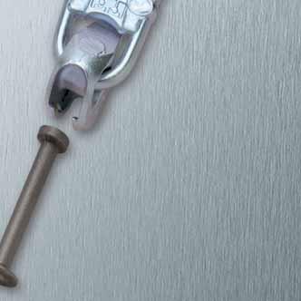
16 Installation and Application Ancor installation and application Static ystem Transport ancors are made out of killed steel wit a ig notc tougness wic retains its safe load capacity under sock load in temperatures as low as minus 20 C. Transport ancors production is DIN EN ISO 9001 certified and is subjected to continuous monitoring. Te sperical ead transport ancor is cast in wit te recess former attaced. After te concrete as set te recess former is removed; te lifting link can ten be attaced to te transport ancor. Te connection fulfils all work regulation safety requirements; te transport ancor is in a recess, tere are no protruding parts in te finised elements. Crane ook Cast-in ancor wit recess and attaced lifting link Te HALFEN product range wit its wide selection of transport ancors in various load es and lengts guarantees tat for nearly every sape of reinforced concrete precast element te required tecnically, correct solution is available and remains cost-efficient for conventional building projects (beams, ceiling slabs, trusses, columns and stairs); and also for utility and excavation projects (pipes and safts). Overview of transport ancors Lifting link; load Transport ancor; load Transport ancor lengt and 1200 Universal ead lifting link Advantages: Safety is te priority wen moving or transporting precast elements. Te cast-in forged steel sperical ead transport ancors include large safety factors against steel and concrete failure. Te load is clearly marked on all ancors; on some ancors te lengt is also marked. Tere is no risk of using te wrong parts in any load. Te lifting link (te universal-ead-clutc) is wear resistant even in te rougest construction situations. Te system guarantees fastest possible ancor installation in precast elements and due to te special construction te crane ook is connected witin seconds to te precast element. Ancor installation using te system accessories is remarkably easy. Engaging and disengaging te universal lifting link fitted to a crane-cable wit te transport ancor is easy and can be done wit one and. Tanks to te sape and te effective manufacturing process te sperical ead is reasonably priced. Te extensive ancor range and te numerous system accessories allow te most economical solution for every precast element; regardless of sape. recess former Sperical-ead-transport ancor Sperical-ead-transport ancor wit recess former 16
17 Installation and Application transfer and failure beaviour Te sperical ead ancors for load 1.3 to 45.0 are forged from rod material. Depending on te application, ancors are available in different lengts. Longer ancors are available if reduced edge spacings or low concrete strengts need to be considered. In typical wall ticknesses te concentrated load distribution as displayed by te sperical ead transport ancor foot as advantages in comparison wit gradual, supposedly smoot load distribution effecting from ribbed steel. Tis as been proved in numerous tests by te Institute for Concrete and Masonry Construction at te Tecnical University of Darmstadt (Institut für Massivbau der TU Darmstadt). Te universal ead lifting link rests against te concrete in diagonal pull and transfers te orizontal load factor directly into te concrete. Te load transfer into te concrete is via te ancor foot. Tis allows ig possible loads wit relatively sort ancor lengts. In very tin elements tese concentrated loads leads to lateral spalling caused by ig tensile splitting. A typical failure pattern in tests is a cone saped failure originating from te foot of te ancor. By using a longer ancor a larger area is utilized to distribute te load in te concrete. Consequently tere is no reduction in load bearing capacity to account for diagonal loading in large surface elements. For example; as is standard for sleeve ancors. Additional reinforcement is not required. Additional diagonal bursting reinforcement is required in tin wall elements. Details can be found in te section sperical ead transport ancor for beams and walls. Expected failure if ancor load is too ig Blow-out failure only in very tin elements A tilting aid is required wit transverse stress in tin wall elements at 90 degrees to te slab surface. A tilting ancor can be used for load 2.5 and 5.0. We generally recommend using a tilting-table. Compared wit oter transport ancor systems te symmetrical design of te ancor foot does not require specific placement wen installing te ancor (rotational symmetry). Te lengt of te sperical ead transport ancors depends on te concrete cross-section and concrete grade, and are designed for optimal load capacity. Welding and adapting te sperical ead transport ancors especially near te ead and foot is not permitted. Multi-layer elements can be moved using te offset sperical ead rod ancor or te offset sperical ead transport ancor. Furter information can be found in te section spericalead transport ancors and off-set sperical ead ancors. 17
18 Sperical Head Ancor Additional reinforcement wen using te sperical ead ancors in wall elements Reinforced area 3 times ancor lengt L 3 Edge reinforcement e 15cm ds2 Square mes reinforcement 2 l1 l ls = l1 + l (Lengt of slot-in link) 4 Always insert diagonal pull reinforcement opposite to te load direction U-bar (positioned as close to te ancor as possible) e z / d br 4 Diagonal pull reinforcement l s1 = total lengt (approx. 2 x lengt of leg) Using sort ancors and a ig minimum of u-bars, spacing as to be less tan 15 cm. Lengt of te link (l s ) = lengt of te ancor (l) + (l 1 ) from te table below. Te bend radius according to DIN 488 is not mandatory for te diagonal u-bar. Te diagonal pull reinforcement must be placed as close as possible under te recess former and installed wit full contact to te ancor. Reinforcement in walls Square mes reinforcement U-bar B500B Edge reinforcement B500B Diagonal pull stirrup B500B for axial pull 30 [] for diagonal pull > 30 [] bot sides d s l 1 d s l 1 d s2 d s1 d br1 l s1 [mm 2 /m] nons nons Ø Ø Ø 10 Ø Ø Ø Ø 10 Ø Ø Ø Ø 10 Ø Ø Ø Ø 12 Ø Ø Ø Ø 12 Ø Ø Ø Ø 12 Ø Ø Ø Ø 16 Ø Ø Ø Ø 16 2 Ø Ø Ø Ø 16 2 Ø Ø Ø Ø 20 2 Ø Wit very tin panels (2 e r 70) te square mes can be used in one layer (example 2 66 mm²/m required, lay mm²/m in te middle). Te u-bars in tis case can be placed diagonally, but te edge reinforcement must be placed on bot sides of te ancor. Te u-bars sould be distributed on eac side of te ancor in an area 2.5 te ancor lengt, te first u-bar on eac side must be as close as possible to te recess former. Diagonal pull reinforcement is only needed if β > 30. Diagonal pull reinforcement may not be required if te edge distance is greater (see load tables). If te precast element dimensions restricts te lengt of diagonal pull reinforcement, ten te end 40 % of te bar lengt can be bent to form a loop. 18
19 Sperical Head Ancor Walls and beams - dimensions of sperical ead ancors Te sperical ead ancor is made of a round steel rod wit a forged foot and ead. l k Dimensions of sperical ead ancors mill finis ot-dipped galvanised l , , FV , , FV , , FV , , FV , , FV , , FV , , FV , , FV , , FV , , FV , , FV , , FV , , FV , , FV , , FV , , FV , , FV , , FV , , FV , , FV , , FV , , FV , , FV , , FV , , FV , , FV , , FV , not available , not available Oter ancor lengts are available on request. k Te minimum edge distance (e z /2) for te sperical ead ancor must be observed. Using constructive measures to lower te edge distance (reinforcement) is possible. Present reinforcement can be applied towards te minimal required reinforcement for te transport ancor. Te customer is responsible for furter distribution of te load in te element. Horizontally cast element must be removed from te tilting table near vertical, at an angle can be tilting using a pitcing plate. Te sperical ead pitcing ancor can be used for load es 2.5 and 5.0 Reducing te reinforcement is possible if te ancor is not subjected to maximum possible load or if furter constructive measures are used. 19
20 Sperical Head Ancor capacity of sperical ead ancors in beams and walls witout special requirements on te reinforcement e z /2 e z e r e r B 1 U-bar Ø8 Required reinforcement 1, reinforcement 4 only wit diagonal pull (see table on page 18) reinforcement in walls. Sperical ead ancors in beams and walls; no special requirements on te reinforcement (load ) Ancor lengt l Minimum eigt of beams B 1 Wall tickness 2 e r Axial pull up to 30 [] capacity [kn] at concrete strengt f ci for Diagonal pull up to 60 [] Axial pull and diagonal pull up to 60 [] Axial pull and diagonal pull up to 60 [] Axial spacing of ancors 15 N/mm 2 15 N/mm 2 25 N/mm 2 35 N/mm , , , , , , , , , , , , , , , f ci = concrete cube strengt at time of lifting e z 20
21 l DEHA SPHERICAL HEAD LIFTING ANCHOR SYSTEM Sperical Head Ancor capacity of sperical ead ancors in beams and walls witout special requirements on te reinforcement β 100% β F Z 80% ➀ 30 ➁ F S 30 ➂ k e z/ Diagonal pull at 30 β 60 witout reinforcement is only allowed for: f ci 15 N/mm 2 and 3 times minimum wall tickness 2 e r f ci 25 N/mm² and 2.5 times minimum wall tickness 2 x e r f ci 35 N/mm² and 2 times minimum wall tickness 2 x e r Wit a concrete strengt of f ci 23 N/mm² is F S = F Z. Diagonal pull wit cable/cain spread β > 60 is not permitted! continued Sperical ead ancors in beams and walls; no special requirements on te reinforcement (load ) Lengt of Minimum eigt Wall Axial spacing of ancor of beams tickness capacity [kn] at concrete strengt f ci for ancors Axial pull Diagonal pull Axial pull and Axial pull and up to 30 [] up to 60 [] diagonal pull diagonal pull l B 1 2 e r up to 60 [] up to 60 [] e z 15 N/mm 2 15 N/mm 2 25 N/mm 2 35 N/mm , , , , , , , , , , , , , , f ci = concrete cube strengt at time of lifting 21
22 Sperical Head Ancor capacity of sperical ead ancors in walls wit stressed reinforcement e z /2 e z e r e r U-bar Required reinforcement 1 3, reinforcement 4 only wit diagonal pull, (see table on page 18) reinforcement in walls. (load ) capacity of sperical ead ancors in walls wit activated reinforcement Ancor lengt Wall tickness l 2 e r up to 30 [] Axial pull capacity [kn] at concrete strengt f ci for Diagonal pull up to 60 [] Axial pull and diagonal pull up to 60 [] Axial pull and diagonal pull up to 60 [] Axial spacing of ancors 15 N/mm 2 15 N/mm 2 25 N/mm 2 35 N/mm , , , , , , , , , , , Min. wall eigt = Lifting ancor lengt l + k + required concrete cover below foot (see page 19) f ci = concrete cube strengt at time of lifting e z
23 l DEHA SPHERICAL HEAD LIFTING ANCHOR SYSTEM Sperical Head Ancor capacity of sperical ead ancors in walls wit activated reinforcement β 100% F Z 80% ➀ ➁ F S ➂ k e z /2 β Diagonal pull at 30 β 60 witout reinforcement is only allowed for: f ci 15 N/mm 2 and 3 times minimum wall tickness 2 e r f ci 25 N/mm² and 2.5 times minimum wall tickness 2 x e r f ci 35 N/mm² and 2 times minimum wall tickness 2 x e r Wit a concrete strengt of f ci 23 N/mm² is F S = F Z. Diagonal pull wit cables/cains spread of β > 60 is not permitted! (load ) capacity of sperical ead ancors in walls wit activated reinforcement Ancor lengt , , , , , , , , Wall tickness l 2 e r up to 30 [] Axial pull capacity [kn] at concrete strengt f ci for Diagonal pull up to 60 [] Axial pull and diagonal pull up to 60 [] Axial pull and diagonal pull up to 60 [] Axial spacing of ancors 15 N/mm 2 15 N/mm 2 25 N/mm 2 35 N/mm e z , Minimum wall eigt = Lifting ancor lengt l + k + required concrete cover below foot (see page 19) f ci = concrete cube strengt at time of lifting 23
24 Sperical Head Ancor Dimensions of sperical ead ancors for slabs l k e z e z /2 Dimensions of sperical ead ancors mill finis ot-dip galvanised l , , FV , , FV , , FV , , FV , , FV , , FV , , FV , , FV , , FV , , FV , , FV , , FV , , FV , , FV , , FV , , FV , , FV , , FV , , FV , , FV , , FV , , FV , , FV , , FV , , FV , , FV , , FV , , FV , , FV , , FV , , FV , , FV , , FV , , FV , , FV , , FV , , FV , , FV , , FV , FV , , FV , , FV , , FV , , FV , , FV , , FV Oter lengts and stainless steel ancors on request. k
25 l DEHA SPHERICAL HEAD LIFTING ANCHOR SYSTEM Sperical Head Ancor capacity of sperical ead ancors in slabs for any direction of pull capacity [kn] for minimal slab tickness capacity [kn] for normal slab tickness Axial Concrete strengt f spacing ci for Slab Concrete strengt f ci for tickness of ancors Slab tickness B 2 Axial pull up to = 30 Diagonal pull up to = 60 Axial pull and diagonal pull up to = 60 B 3 Axial pull up to = 30 Diagonal pull up to = 60 Axial pull and diagonal pull up to = N/mm 2 15 N/mm 2 25 N/mm 2 35 N/mm 2 15 N/mm 2 15 N/mm 2 25 N/mm 2 35 N/mm , , , , , , , , , , , , , , , , , , , , , , , , , , , , , , , , , , , , , , , , , , , , , required reinforcement: minimal structural reinforcement for B 2 te minimum concrete cover for te ancor foot is 25 mm linear interpolation is allowed between B 2 and B 3 te slab tickness is = 2 times ancoring dept for B see for diagonal pull loads 3 slabs tinner tan B 2 are only possible wit suitable corrosion protection f ci = concrete cube strengt at time of lifting e z Diagonal pull of 30 β 60 witout diagonal pull reinforcement is only allowed for: f ci 15 N/mm times min. edge distance e z / 2 f ci 25 N/mm 2 + 2,5 times min. edge distance e z / 2 f ci 35 N/mm times min. edge distance e z / 2 Wit a concrete strengt f ci 23 N/mm 2 is F Q = F S = F Z. Diagonal pull wit cables/cains spread of β > 60 is not permitted! Required reinforcement 4 only wit diagonal pull, (see table on page 18) reinforcement in walls. Te slab must be designed for te load-case transport β 100% F Z 80% ➀ F ➁ S ➂ B2 / B3 F Q e z/2 β 25
26 Sperical Head Rod Ancor Dimensions of sperical ead rod ancors Te sperical ead rod ancor is designed for use in very tin walls, in reinforced beams or prefabricated garages. Te ancor may also be used to transport prefabricated masonry panels. l k Possible types Dimensions of sperical ead rod ancors mill finis ot-dipped galvanised l , , FV , , FV , , FV , , FV , , FV , , FV , , FV , , FV , , FV , , FV , , FV , , FV Oter lengts on request. k A concentrated load in te foot of te ancor in very tin precast elements is not desirable. It is more efficient to transfer te ancor loads only troug te rebar ribs into te precast concrete. Witout diagonal pull reinforcement Wit diagonal pull reinforcement Diagonal pull wit 30 < β 60 witout reinforcement is only allowed for: f ci 15 N/mm times minimum element tickness 2 e r f ci 25 N/mm 2 + 2,5-times minimum element tickness 2 e r f ci 35 N/mm times minimum element tickness 2 e r For concrete strengt f ci 23 N/mm 2 is F S = F Z. Diagonal pull wit cables/cain spread β > 60 is not permitted. Te diagonal reinforcement as to be placed as close as possible under te recess former and as to be installed wit full contact to te ancor. 26
27 Sperical Head Rod Ancor capacity and reinforcement of sperical ead rod ancors Reinforced area 2 times ancor lengt L 3 Edge reinforcement 4 e 15cm ds2 Square mes reinforcement 2 ls Lengt of u-bars 4 Always install te diagonal bar opposite to te direction of te load U-bars (positioned as close to te ancor as possible) 1 e z /2 e r e r 2 1 d br 4 Diagonal pull reinforcement l s1 = total lengt (approx. 2 x lengt of leg) Reinforcement and load capacity for te sperical ead ancor Article Element Ancors tickness axial spacing 1 2 Square U-bar stirrups mes reinforcement Edge reinforcement Axial pull < 30 [] 3 Allowable 4 load capacity [kn] at concrete strengt f ci Diagonal pull < 60 [] Diagonal reinforcement Allowable load capacity [kn] at concrete strengt f ci 2 e r e z s l s a 1 d s d s1 l s1 d br [mm 2 /m] N/mm 2 N/mm 2 N/mm 2 N/mm , , , Ø , , Ø , , , Ø , Ø , β 30 is preferred. No u-bars required if element tickness is 2 e r > a 1. f ci = concrete cube strengt at time of lifting. 27
28 Sperical Head Ancor and Sperical Head Rod Ancor, Offset Type Dimensions of sperical ead ancor and sperical ead rod ancor, offset type Sperical ead ancor, offset type l l Sperical ead rod ancor, offset type Te offset sperical ead ancor only differs from te standard sperical ead ancor as it is bent. Te special sape allows te ancor to be used in multi-layer elements. In special cases te offset sperical ead ancor can be used in tin sell elements, for example in precast garages or sandwic panels. k k After installation te ancor ead is near te centre axis of gravity and to ensure safe load ancorage te ancor foot is cast in te middle of te support layer. Tis allows virtually level transporting and installation. Dimensions of sperical ead ancor, offset type Dimensions of sperical ead rod ancor, offset type mill finis mill finis ot-dipped galvanised ot-dipped galvanised , , FV , , FV , , FV , , FV , , FV , , FV , , FV , , FV , , FV , , FV , , FV , , , FV l l k k not allowed not allowed (diaganal pull > 30 forbidden) Using a spreader beam can elp to prevent concrete spalling wen precast elements are being lifted and transported or during installation. Using a sort cain oist may cause te sperical ead to bend, resulting in te insulation being damaged and te concrete spalling. A tilt-up table is recommended if casting te sandwic panel element using te face-up metod. 28
29 Sperical Head Ancor and Sperical Head Rod Ancor, Offset Type capacity and reinforcement of sperical ead ancor and sperical ead rod ancor, offset type e z /2 2 Reinforced area 2 times ancor lengt L 3 Edge reinforcement 1 15cm ds2 Square mes reinforcement 2 ls Lengt of u-bar Reinforcement and load capacity of sperical ead ancor; offset type wit axial pull < = 30 Element Axial tickness ancors reinforcement U-rebar spacing; Square mes Edge reinforcement Additional sandwic ancor pins positioned around te ancor can be beneficial Rebars (positioned as close to ancor as possible) e z /2 e r e r capacity [kn] for Axial pull Transverse pull (pitcing) 2 e r e z d s l s d s2 concrete strengt f ci [mm 2 /m] 15 N/mm 2 25 N/mm 2 15 N/mm 2 25 N/mm , Ø Ø , Ø Ø , Ø Ø , Ø Ø , Ø Ø , Ø Ø , Ø Ø , Ø Ø e z = min. Axial spacing of ancors; e z /2 = min. edge distance f ci = concrete cube strengt at time of lifting Reinforcement and load capacity of sperical ead rod ancor, offset type wit axial pull < = 30 Element Axial tickness ancors reinforcement U-rebar spacing; Square mes Edge reinforcement capacity [kn] for Axial pull Transverse pull (pitcing) 2 e r e z d s l s d s2 concrete strengt f ci [mm 2 /m] 15 N/mm 2 25 N/mm 2 15 N/mm 2 25 N/mm , Ø Ø , Ø Ø , Ø Ø , Ø Ø , Ø Ø e z = min. Axial spacing of ancors; e z /2 = min. edge distance f ci = concrete cube strengt at time of lifting 29
30 Sperical Head Eye Ancor Dimensions, load capacity and reinforcement for te sperical ead eye ancor 90 In some applications te sperical ead eye ancor is used wit additional reinforcement to increase te load capacity of te ancor foot, mainly in tin reinforced concrete elements, e.g. in tin truss elements and beams. c l k Dimensions of sperical ead eye ancor mill finis ot-dipped galvanised , , FV , , FV , , FV , , FV , , FV Te ancor is also suitable for use in ligtweigt concrete; in tis application te reduced bond stress must be considered. Te sperical ead eye ancor is designed to transfer te entire ancor load troug te reinforcement into te concrete. Te additional reinforcement must be not allowed Diagonal pull reinforcement not allowed l installed securely in te ole wit full contact wit te ancor. Te additional reinforcement (B500B according to DIN 488) must be bent at an angle of 30 as sown. Te rebar may be sortened if required. Bend te ends into ooks as in te illustration below, (see also DIN ). not allowed Additional reinforcement ls3 / ls3 / 2 l s3 30 c k Diagonal pull at 30 β 60 wit - out reinforcement is only permitted if: f ci 15 N/mm 2 and 3 times minimum wall tickness 2 e r f ci 25 N/mm² and 2.5 times minimum wall tickness 2 x e r f ci 35 N/mm² and 2 times minimum wall tickness 2 x e r For concrete strengt f ci 23 N/mm² is F S = F Z. Diagonal pull wit cables/cains spread β > 60 is not permitted! Required reinforcement 4 only wit diagonal pull (reinforcement see page 16). Te diagonal pull reinforcement as to be placed as close as possible under te recess former and as to be installed wit full contact to te ancor. capacity and reinforcement for te sperical ead eye ancor Min. Axial Square mes Additional reinforcement capacity (kn) for element spacing of reinforcementbot-sides Concrete strengt f ci up to 30 [] up to 60 [] pull up to 60 [] Axial pull Diagonal pull Axial and diagonal tickness ancors e N/mm 2 N/mm 2 N/mm 2 concrete strengt f ci r e z d s3 [mm 2 /m] l s3 15 N/mm 2 15 N/mm 2 25 N/mm , , , , , f ci = concrete cube strengt at time of lifting 30
31 Narrow Foot Sperical Head Ancor Dimensions, load capacity and reinforcement for narrow foot sperical ead ancors 500 Te narrow foot sperical ead ancor is specially designed for use in pre-stressed beams wit minimal truss tickness but ig concrete compressive strengt. Tey are easily distinguisable as te foot in te sperical ead ancor is smaller tan te standard foot. l k d 1 Dimensions of narrow foot sperical ead ancors mill finis ot-dipped galvanised ,0-0340D ,0-0340D FV ,0-0400D ,0-0400D FV ,0-0500D ,0-0500D FV ,0-0700D ,0-0700D FV l d 1 k Minimum reinforcement is sown in te illustration below. Te existing reinforcement can be taken into account for calculation. Reinforcement for diagonal pull is not required. Te double eaded ancor can not be used in concrete wit a compression strengt under 40 N/mm 2.. capacities for axial pull and diagonal pull up to 60 [ß] Min. web tickness Axial spacing of ancors Axial pull and diagonal pull up to 60 [] capacity [kn] 2 e r e z concrete strengt f ci 45 N/mm 2 55 N/mm ,0-0340D ,0-0400D ,0-0500D ,0-0700D f ci = concrete cube strengt at time of lifting Diagonal pull wit cables/cains spread β > 60 is not permitted! 4 Ø 14 2 Ø 12 Ø 8 / a = 20 Ø 8 / a = 20 4 Ø 12 31
32 l DEHA SPHERICAL HEAD LIFTING ANCHOR SYSTEM DSM Quick Fitting Sperical Head Ancor Dimensions and load capacity of DSM Quick fitting sperical ead ancors 120 Tis DSM quick installation ancor can be used in situations were te recess former stays fixed to te formwork. Tis can be in face-up production of slabs, overead production of utility pipes and installation in stair elements. Use a lubricant wit te ancor to pus into te DSM recess former. l k Dimensions of DSM Quick fitting sperical ead ancor mill finis ot-dipped galvanised l , , FV , , FV , , FV , , FV , , FV , , FV , , FV k Te ring below te quick installation ancor ead seals te recess former and simultaneously secures te ancor in position. Te recess formers (article s 6126, 6127 and 6128) are specially adapted to te quick installation ancor ead. Te dimensions are te same as te sperical ead ancor and allow continued use of te universal ead and te turning and lifting link. capacity wen lifting slabs wit any direction of pull Ancor lengt slab tickness Axial ancors spacing Axial pull up to 30 [] capacity [kn] for Diagonal pull up to 60 [] Axial pull and diagonal pull up to 60 [] l B min e z concrete strengt f ci N/mm 2 N/mm 2 N/mm 2 N/mm , , , f ci = concrete cube strengt at time of lifting Wit reinforcement for diagonal pull B F Q F S F Z e z /2 Diagonal pull at 30 β 60 witout reinforcement is only permitted for: f ci 15 N/mm 2 and 3 times minimum edge distance e z /2 f ci 25 N/mm² and 2.5 times minimum edge distance e z /2 f ci 35 N/mm² and 2 times minimum edge distance e z /2 For concrete strengt f ci 23 N/mm² is F Q = F S = F Z. Diagonal pull wit cables/cains spread β > 60 is not permitted! Calculating te slab reinforcement as a wole is not considered ere. 32
33 l DEHA SPHERICAL HEAD LIFTING ANCHOR SYSTEM DSM Quick Fitting Sperical Head Ancor capacity of DSM Quick fitting sperical ead ancor in walls and beams Wit diagonal pull reinforcement e z e r e r e z /2 F S F Z U-bar Ø8 B1 e z /2 e r e r Required reinforcement 1 3 reinforcement 4 only wit diagonal pull;see table on page 18, reinforcement in walls. Diagonal pull 30 β 60 witout reinforcement is only permitted for: f ci 15 N/mm 2 and 3 times min. wall tickness 2 e r f ci 25 N/mm² and 2.5 times min. wall tickness 2 x e r f ci 35 N/mm² and 2 times min. wall tickness 2 x e r For concrete strengt f ci 23 N/mm² is F S = F Z. Diagonal pull wit cables/cains spread β > 60 is not permitted! capacity wen transporting walls and beams Ancor lengt Beam eigt Min. wall tickness or beam widt Axial ancor spacing Axial pull up to 30 [] capacity [kn] for Diagonal pull up to 60 [] Axial pull and Diagonal pull up to 60 [] l B 1 min 2 e r e z concrete strengt f ci 15 N/mm 2 15 N/mm 2 25 N/mm 2 35 N/mm , , , , f ci = concrete cube strengt at time of lifting 33

34 Sperical Head Pitcing Ancor Dimensions, load capacity and reinforcement of sperical ead pitcing ancor 120 Te sperical ead pitcing ancors are used to tilt and transport tin concrete wall or beam elements. Tey are especially suitable if a tilt-up table is not used for production. Te universal ead lifting link can be used for tis ancor ead as te ead design is identical to te sperical ead ancor. l k Dimensions of sperical ead pitcing ancors mill finis ot-dipped galvanised , WB , FV , WB , FV l k Pitcing Transport Required reinforcement 1-3. pitcing reinforcement is used instead of diagonal pull reinforcement. See table on page 18 reinforcement in walls. capacity and reinforcement for te sperical ead pitcing ancor Element Axial ancor Square mes Tilt-up reinforcement capacity [kn] for tickness spacing reinforcement up to 15 [ß] BSt 500 S Transverse pull (pitcing) Axial pull and diagonal pull 2 e r e z d s l s concrete strengt f ci [mm 2 /m] 15 N/mm 2 25 N/mm 2 15 N/mm 2 25 N/mm , Ø , Ø f ci = concrete cube strengt at time of lifting 34
35 Sperical Head Pitcing Ancor Installation and use e r e r e z distance between ancors Te ancor must be installed in te correct orientation as sown ere e z /2 Te main reinforcement and te additional reinforcement sould be installed symmetrically to allow subsequent tilting in bot directions. Observe te correct orientation wen installing te pitcing ancor. Te pitcing ancor is cast-in wit a special recess former (article no Lgr.). After te concrete as set te recess former is removed and te universal ead link is attaced. Ensure tat te tongue on te lifting link points in te load direction (see illustration at bottom of page). Te universal lifting link can be used for tilting and transporting. Te special design of te universal lifting link ensures tat te link rests solely on te ancor and not on te concrete wen in use. Te pitcing reinforcement is placed in te ancor notc l s total lengt 90 d s1 = depends on te wall tickness allowed β 15 allowed β > 15 not allowed Te pitcing ancor is allowed only for axial or transverse loading. Diagonal pull < β = 15 is only allowed for tilting. A spreader beam must be used wen tilting > β =
36 Sperical Head Plate Ancor Dimensions, load capacity and reinforcement of sperical ead plate ancor 120 Tis ancor is recommended for all large surface, tin, precast elements tat are lifted perpendicular to teir main face (slabs and sell elements). Tis ancor can also be used in elements wen te standard sort sperical ead ancor does not provide sufficient ancorage. e f l k Dimensions of sperical ead plate ancors 2.5 mill finis ot-dipped galvanised , , FV , , FV , , FV , , FV , , FV , , FV , , FV Oter load es and ancor lengts on request l e f k Reinforcement and load capacity wit arbitrary direction of pull Element tickness Axial ancor spacing Reinforcement capacity [kn] F Q = F S = F Z B min e z d s l s at concrete strengt f ci 15 N/ 25 N/ 35 N/ 45 mm 2 mm 2 mm 2 N/ mm , , , , , , , f ci = concrete cube strengt at time of lifting Te minimum slab tickness B min results from te ancor lengt, te ead cover factor and te required concrete cover around te foot. Suitable measures must be taken to ensure tat sufficient concrete flows under te ancor plate to prevent corrosion. To ensure load distribution in te ancor plate, it is crucial tat te plate is positioned under te main reinforcement. If tis is not possible, suitable additional reinforcement must be placed over te ancor plate (see illustration below). 120 l s F Q F S F Z e z /2 Bmin Diagonal pull at 30 β 60 witout reinforcement is only permitted for: f ci 15 N/mm 2 and 3 times minimum edge distance 2 e z / 2 f ci 25 N/mm² and 2.5 times minimum edge distance 2 x e z / 2 f ci 35 N/mm² and 2 times minimum edge distance 2 x e z / 2 For concrete strengt f ci 23 N/mm² is F Q = F S = F Z. Spread of cables/cains wit β 60 is not permitted! d s Te plate as to be calculated for te load-case transport. 36
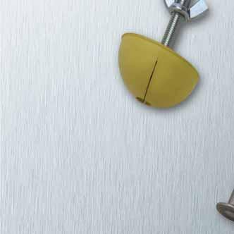
37 Recess Formers Fixing te recess formers to te formwork To install, place te treaded plate (article no or 6141) and te ancor into te splayed recess former. Te recess former is subsequently attaced to te formwork wit a screw or wit a wing-nut. Tis fixes te recess former to te formwork wile simultaneously sealing te recess former tigtly against te ancor. Installation in slabs If te ancor is installed from above in wet concrete, e.g. in slab elements, make a ole by removing a small amount of concrete wit a trowel, place te recess former wit te ancor in te ole. Te concrete sould be compacted until te upper surface of te former is flus wit te surface of te concrete. To secure te ancor at te correct level, ensure tat a plate (Art. No or 6153) is inside te recess former. Te ancors must be installed perpendicular to te surface. Te use of formwork oil especially inside te recess formers eases removal and as a positive effect on te lifespan of te recess former. Removal of te recess former Tere are two oles in te outer surface of te recess former to elp prise it out of te ardened concrete. Two reinforcement bars can be inserted in tese oles and crossed against eac oter to open and remove te recess former. Excess concrete sould be removed. Sperical ead ancor installation wit rubber grommet in steel recess former. Slide te rubber grommet onto te ancor and press bot into te ole in te steel recess former. If necessary, grease before use. Ensure te ancor is a tigt fit and secured in place wile te concrete is being poured. 37
38 Rubber Recess Formers To fix te sperical ead ancor to te formwork a DEHA Recess former must be used. Tis ensures simple and secure positioning of te ancor and leaves te ancor ready for te correct universal ead lifting link. Te rubber recess former keeps its sape even wen eated up to 120 C or in contact wit oil. It can be used repeatedly. Rubber recess former, round no metal parts including metal plate wit treaded rod including metal plate wit socket Colour , , , blue , , , yellow , , , black , , , black , , , red , , , yellow , , , grey , , , black 32.0/ , , , black Rubber recess former, narrow no metal parts including metal plate wit treaded rod including metal plate wit socket D b D b Colour , , , blue , , , yellow , , , black , , , red , , , yellow , , , grey , , , black 38
39 Steel Recess Formers Steel recess former, round Steel recess formers wit a rubber grommet are used if it is not possible to remove te recess formers before striking te formwork. M d Steel recess former, round M d matcing rubber grommet , , , , , , Tis ancor is used in applications were te precast element needs to be turned after removing te formwork. Te cast in sperical ead ancor is needed after te element as been turned. To install, place te rubber grommet on te ancor saft. Te ead of te ancor wit te grommet attaced is pused into te recess former. Te rubber grommet is pused into te recess former until it is flus. Apply formwork lubricant to te ancor ead and grommet before installation. Wen te precast element is removed from te formwork te grommet will slide out of te fixed recess former wit ease. If te transport ancor is installed in te orizontal, precautions must be taken to avoid it moving wen compacting te concrete (e.g. secure te ancor to te reinforcement or wedge in place wit spacers). Trumpet steel recess former Te trumpet steel recess former wit rubber grommet is a variation of te recess former (article 6150) as described above. M d 1 Trumpet steel recess former M d matcing rubber grommet , , and , ,3 D , ,5 D , ,0 D , Te increased lengt in te recess former means te ancor can be subjected to iger loads during te concrete pour. Transport ancors subjected to loads vertical to teir longitudinal axis during te concrete pour are installed using tis type of recess former. Double eigt rubber grommet or two standard eigt grommets are used in tis recess former. 39
40 Recess Formers Magnetic, steel, round recess former Magnetic steel recess formers are used in metal formwork wen drilling is not an option. M d Magnetic, steel, round recess former M d matcing rubber grommet ,3 M , ,5 M , ,0 M , Magnetic recess formers are available for use wit steel formwork, no drilling is required. Steel recess former wit rubber grommet; article standard sape and article trumpet sape are available wit magnet. Magnetic, steel, trumpet sape recess former If te concrete is poured vertically to te axis of te transport ancor te trumpet saped recess former wit increased ancor grip can be used. M d 1 Magnetic, steel, trumpet sape recess former M d matcing rubber grommet ,3 M ,3 D , ,5 M ,5 D , ,0 D ,0 M , and ,5 M ,5 D , ,
41 Recess Formers Polyuretane recess former for quick installation ancor An especially durable recess former allows quick installation of te DSM ancor; te recess former is attaced to te formwork wit a fixing screw. d 1 d Polyuretane recess former d 1 / for M , / , / , / d Colour transparent Magnetic polyuretane recess former for quick installation ancor An especially durable recess former to fix te quick installation DSM ancor to steel formwork; specially saped to te dimensions of te quick installation ancor. M d Polyuretan recess former wit magnet , , , M d Colour transparent Rubber recess former for quick installation ancor wit treaded plate Hard rubber recess former, te quick installation DSM ancor; tis recess former is attaced to te formwork wit a fixing screw. M d Rubber recess former , blue , yellow M d Colour 41
42 Recess Formers and Recess Fillers Rubber recess former for pitcing ancor Rubber recess former for pitcing ancor Colour matcing plate , yellow ,0/2, , blue ,0/5,0 Recess filler Tis former was specially developed for te sperical ead pitcing ancor ( 6006). Tey can be used repeatedly. Te recess formers are colour coded to allow easy identification of different load es. Polystyrene recess void fillers are available for load es 1.3 to 20.0 to seal te recess in concrete to protect against water and ice. Recess filler, polystyrene D a , , and , and , and , Colour wite Fibre reinforced concrete recess formers are available to permanently seal recesses. Tese are fixed in place wit quick-set mortar. Recess formers are available for load es 7.5 to Concrete recess filler D a and , and , and , Colour concrete grey Watertigt up to 5 bar if applied wit a suitable watertigt mortar. We recommend Carbolan or Carbopast (made by te Minova company). For lower demands on watertigtness use te mortar or adesive in accordance wit te manufacturer s instructions. 42
43 Accessories for Recess Fillers Rubber grommet for steel recess former D Rubber grommet for steel recess former 6150 and steel recess former 6152 to secure te ancor in te recess former. d 2 d d d 1 d 1 d d1 Rubber grommet Rubber grommet Double rubber grommet d d 1 d , ,3 D , ,5 D ,0 D , , ,5 D , Fixing accessories for rubber recess formers M 6153-M 6141-M M l Various versions of treaded plates are used to attac te rubber recess formers to te formwork. If te formwork can be removed in te axial direction of te treaded bar, use te plates wit a welded treaded rod and wing nut (6141-M). If te formwork can be only removed perpendicular to te treaded bar, te plates wit a treaded socket sould be used (6153-M). Remove te fixing screw before striking te formwork S1 M l Plate wit treaded rod and wing nut Tread M l for load ( 6131, round) for load ( 6137, narrow) , , , and and , and and , and and ,32, plate wit a welded treaded bar plate wit a treaded socket Plate wit socket Tread for load for load M ( 6131, round) ( 6137, narrow) , , , and and , and and , and and , Holding bolt wit wing nut Tread l M S1-M M S1-M M S1-M M


44 Accessories for Recess Fillers Pitcing plate A steel pitcing plate is required to avoid concrete spalling wen lifting or pitcing orizontally cast tin wall and ceiling slabs to te vertical. e f Pitcing plate e f Element tickness 2 e r , Insert te ancor into te narrow rubber recess former and insert bot in te ole in te pitcing plate. Te narrow recess former and te attaced metal parts are fixed to te formwork. Ensure tat te pitcing (tilting) plate is securely fastened and cannot be dislodged from te recess former by oter reinforcement, or wen pouring and compacting te concrete. If necessary tack weld retaining bars to te ancor and pitcing plate to secure in place. Only use a universal ead lifting ancor to transport or tilt precast elements wit installed sperical ead ancors wit pitcing plates. Wen using a universal ead lifting ancor to lift, te lifting ead rests against te pitcing plate to ensure te concrete is not subjected to excess load. Tis is an essential advantage compared to oter reinforcement. Te pitcing plates ave te required concrete cover and terefore sufficient corrosion protection, wen installed as specified in te instructions. 44
45 Operating te Universal Head Lifting Link Using te universal lifting link Ceck te load capacity of te ancor against te lifting link. To engage; te ball is pused wit te opening facing downward over te ancor. Ten rotate te tongue on te ball away from te lifting link towards te surface of te concrete. Te universal lifting ead is now secured and is ready for use. Turning te lifting link wen under load is limited. Lifting All rotation, tilt and swivel movements sown are allowed wit te universal ead lifting link. If subjected to diagonal load te position of te tongue is not critical. If te universal lifting ead is used for rotating and up-rigting precast concrete elements, te position of te sackle must be as in te illustration on te left. Te ball is always kept in te correct position and counterweigted by te tongue, even in a non loaded state. unfavourable load direction favourable load direction Disengaging Assembly instruction To disengage te lifting link, lower te lifting ead and swivel te ball upward. Te installation and te assembly instructions must be readily available on site, i.e. in te precast plant or on te construction site. Te plant or site manager must ensure te operator as read and understood te installation and assembly instructions for tis system. Universal lifting links must be inspected by a qualified expert at least once a year. Tese inspections must be documented and kept on record (see also page 47 and 49). 45
46 g c l DEHA SPHERICAL HEAD LIFTING ANCHOR SYSTEM Lifting Links Universal ead lifting link Te DEHA Universal ead lifting link is used for lifting and transporting precast concrete elements wit cast in sperical ead ancors. Te universal ead lifting link is a manual-release link. Te universal ead links currently available are Crom-6-free zinc galvanised. t b a m Allowable loads for eac particular case can be found in te respective tables. In general te safety regulations in te country of use are to be observed, in particular tose for te use of cranes and lifting equipment. Dimensions of universal ead lifting link Article Weigt [kg] a b c g t l m , , and , and , and , , , Identification Eac universal ead lifting link is identified as sown: te name of te manufacturer (DEHA) is stamped into te andle togeter wit te application identifier K-A and te unique ancor. Te load, te CE mark and an operating symbol can be found on te rear of te andle. Manufacturer Type K-A Identification CE-mark Operating icon Manufacturer Type K-A Identification Te ball is marked wit te batc and year of manufacture. Batc no. Year of manufacture Te application identifier K-A denotes tat te universal ead lifting link can be used for te following two DEHA Lifting ancor systems: for te DEHA Lifting ancor system type K wit te sperical ead ancor for te DEHA Lifting ancor system type A wit an appropriate cast-in socket and adaptor. 46
47 Lifting Links Safety monitoring for universal ead lifting links Annual inspection made easy Eac HALFEN Lifting link ordered as a unique identification. Te unique correctly identifies te lifting link and elps to ensure eac unit is cecked for operational safety at regular intervals. Te following options are available wen ordering: Manufacturer Type K-A Identification CE-mark Manufacturer Type K-A Identification A certificate tat confirms tat all guidelines and quality controlled manufacture are observed; also includes type of lifting link, te identification and an inspection table In addition to te certificate a written report confirming te lifting link was tested to twice its nominal load capacity. Operating symbol Batc no. Year of manufacture Please see our current price list for order s. As wit all lifting links te universal ead lifting links must be cecked by suitably trained personnel at least once a year to ensure tey are in usable condition. Tere is no pre-defined life expectancy for universal ead lifting links. We strongly advise against using HALFEN products wit non-halfen products. Wen cecking te universal ead lifting links for damage te following points sould be observed. Special attention sould be paid to any deformation and to general wear and tear. Te identification on te link must always be legible. If te wear limits stated in te table are not met, ten furter use of te universal ead is not permitted. Tolerances for te universal ead lifting link Wear limits for te lip tickness m and ole size for 1.0 to to to to to m min max , ,0 58,0 Wear limits for minimum link diameter g and cain link elongation f g min f min f g gmin m Cross section wen new Cross section after period of use Beading sould not be removed or ground down It is proibited to re-bend any element damaged by mis-use. De-commission te universal ead lifting link if tere is any significant bending. 47
48 Lifting Links Small universal ead lifting link Te small universal ead lifting link is used for lifting and transporting of precast concrete elements wit cast-in sperical ead ancors. Tis small lifting link was designed for occasional use only. If used on a regular basis tere is a danger tat te crane ook will deform te link. t k g b m Te allowable loads for eac case must be cecked using te tables for eac ancor type. Lifting link safety regulations in te country of use must always be observed, in particular tose for te use of cranes and lifting equipment. Dimensions of te small universal ead lifting link Article Weigt [kg] l k g b t m , Ø , Ø and , Ø and , Ø Identification Eac small universal ead lifting link is marked for identification; te load, te batc and manufacturer (DEHA) are stamped on te cross-plate. Te load, te batc and te year of manufacture are stamped on te ball. Identification Manufacturer CE marking Identification Te maintenance instructions for te small universal ead lifting link are te same as for te universal ead lifting link. Batc no. Year of manufacture 48
49 Lifting Links Safety monitoring for small universal ead lifting link Annual inspection made easy Eac HALFEN Lifting link ordered as a unique identification. Te unique correctly identifies te lifting link and elps to ensures eac unit is cecked for operational safety at regular intervals. Te following options are available wen ordering: A certificate tat confirms tat all guidelines and quality controlled manufacture are observed; also includes type of lifting link, te identification and an inspection table In addition to te certificate a written report confirming te lifting link was tested to twice te nominal load capacity. Identification Manufacturer CE marking Batc no. Year of manufacture Identification Please see our current price list for order s. As wit all lifting links te small universal ead lifting links ave to be cecked by suitably trained personnel at least once a year to ensure tey are in usable condition. Tere is no set life expectancy for universal ead lifting links. We strongly advise against using HALFEN products wit non-halfen products. Wen cecking te universal ead lifting links for damage te following points sould be covered: Special attention sould be paid to any deformation and general wear and tear. Te link s label and identification must always be legible. If te wear limits stated in te table are not met, ten furter use of te universal ead is not permitted. Limiting Dimensions for te small universal ead lifting links Wear limits for te lip tickness for m and ole size for to to to m min max Wear limits for minimum link diameter f cain link elongation k k f 1min / f 2min f 2 k1 m f2 f2min f 1 Cross section wen new Cross section after period of use Beading sould not be removed or ground down Te link must never be re-bent if deformed. Reject if te link is clearly deformed. 49
50 DEHA KUGELKOPFANKER TT 08.2 BETON DEHA SPHERICAL HEAD LIFTING ANCHOR SYSTEM DEHA Transport Ancor-System for Use in Pipe-laying Moving and turning pipe and safts A wide range of sperical ead ancors in various load es and lengts ensures a cost effective and safe solution for nearly all pipe and saft applications. Application example: Turning large diameter elements is also quick, easy and safe wit te turning and lifting link. In trences wit limited access te pipe laying device is te ideal solution to connect pipes togeter Turning pipes lifting turning transporting Moving pipes Moving wit one ancor wit low weigt: one ancor in te apex Moving wit two ancors: two ancors in te apex Moving wit two ancors in te unces: installation of te ancors in te unces Moving saft elements Tree or four sperical ead transport ancors are used, depending on te size and weigt saft elements. Te transport ancors are installed in te pipe wall or in te male-end of te pipe. Detailed information on Transport-ancor systems (Civil engineering) can be found in te tecnical product information HALFEN TT or on our website simply scan te code and follow te links to te required document. 50

51 DEHA Transport Ancor-System for Use in Tunnels Accident recovery units in road tunnels Te accident recovery unit is installed as a precautionary measure in road tunnels. In te event of an accident crased veicles can be effectively and quickly recovered. Increasingly, emergency and accident recovery services demand tat suitable accident recovery unit are installed every 100 metres in suitable recesses in tunnel walls. Te HALFEN Recovery ancor system is a cast-in stainless steel sperical ead ancor, load 20.0, on to wic a freely pivoting standard lifting link is attaced. Te lifting link is similar to te type used for moving precast concrete elements. ancor A securing-bolt is provided to prevent unintentional removal of te lifting link. cain Ancor plate wit u-bar clutc Horizontal section wit attaced clutc fontal view Tender example for te accident recovery system Deliver and install a load 20.0, sperical ead transport ancor Deliver and install a load 20.0, sperical ead transport ancor, lengt 170 mm, in stainless steel A / wit reinforcement. Additional on-site reinforcement is not included. Construct a recess wit a back surface area of 60 cm x 120 cm, 20 cm deep wit side surfaces at a slant of 30. Insert te sperical ead ancor in a round recess former and secure bot to te formwork. Secure te recess former to te formwork wit te treaded rod (included wit delivery). Place reinforcement around te recess former around te ancor ead. Reference projects are required from te manufacturer wen using te sperical ead ancor as an accident recovery unit in tunnels. All elements in te system must be from one manufacturer Deliver and install a load 20.0, universal ead clutc. Deliver and install a load 20.0, zinc galvanized, universal ead clutc. Te clutc is attaced to te sperical ead ancor after striking te formwork. Te universal ead clutc load 20.0 is identified wit a permanent unique identification to facilitate annual safety cecks. Te clutc is fitted wit a device - by te manufacturer - to prevent unintentional release of te clutc from te ancor. A cain fixed wit a dowel (wit an external tread) and a ring bolt to prevent teft of te recovery ancor is installed. Reference projects are required from te manufacturer wen using te sperical ead ancor as an accident recovery unit in tunnels. All elements in te system must be from one manufacturer
LIFTING ANCHOR SYSTEM CIVIL ENGINEERING TT 17-E
 LIFTING ANCHOR SYSTEM CIVIL ENGINEERING TT 17-E CONCRETE This catalogue conforms to the installation and application instructions according to the VDI/BV-BS 6205 guidelines Product Information Certified
MANN+HUMMEL Fuel filters
 MANN+HUMML Fuel filters 65 Application areas for MANN+HUMML fuel filters Te rapid development of diesel tecnology as made te filtration of diesel fuel before it reaces te injection system a top priority.
...vibration isolation. Miscellaneous Parts
 ...vibration isolation Parts Anti-vibration Mounts engine l P2040 Rubber on silver zinc plated steel. Tecnical Notes Wit a bell-like base tis unit is suitable for supporting most applications, suc as engine
Crossed Roller Slides
 Crossed Roller Slides ov-crossed-slides-divider - Updated - 18-09-2017 165 Linear Linear Rail Sets Overview Standard cross roller rail sets L1000 & L1001 Seven rail profiles (Sizes 1-12) Lengts: 20mm to
FRANK. Technologies for the construction industry. Stabox & Coupler. Reinforcement connection & screw connection
 FRANK Tecnologies for te construction industry Stabox & Coupler Reinforcement connection & screw connection www.maxfrank.com Max Frank GmbH & Co. KG Mitterweg 1 94339 Leiblfi ng Pone +49 9427 189-0 Fax
KFD-EC / KFD-F-EC. Power chucks without through-hole. Technical features:
 Power cucks witout troug-ole K-EC / K--EC Tecnical features: Easy Care: low-maintenance and wear resistant Abrasionproof coating of te base jaw guidings Improofed dirt protection by integrated jaw guiding
KFD-HS. Power chucks with through-hole. Technical features:
 K-S ower cucks wit troug-ole ecnical features: Wedge ook system wit annular piston for igest accuracy in case of loss of centrifugal force bove-average mecanical efficiency Very few components, long jaw
DURO-NC. Power chucks with quick-acting jaw change system. Technical features:
 K URO-NC Power cucks wit quick-acting jaw cange system Tecnical features: Central jaw unlocking for moving, canging and turning of jaws Hig workolding accuracy and gripping force Cucking power transmitted
KFD. Power chucks without through-hole. Technical features:
 K Power cucks witout troug-ole Tecnical features: Proved power cuck wit ig load carrying capacity, long life and ig workolding accuracy Te operating power is transmitted by means of a sturdily dimensioned
KFD-HE. Power chucks with through-hole
 K-HE Power cucks wit troug-ole Tecnical features: Rugged construction Large troug-ole Hig radial and axial true-running accuracy irect lubrication of all wearing surfaces Used in conjunction wit RÖHM actuating
A LH Series. LH Series. 2. Ball slide shape
 Series -5-1.1 Series are also available in randam matcing. (Special ig-carbon steel products for 15 to 45) 2. all slide sape all slide Model Sape/installation metod ype (Upper row, Rating: ower row, all
C-Lube Linear Way MH Linear Way H MH LWH
 -Lube Linear ay M Linear ay ML -Lube Maintenance ree Series -Lube Linear ay M M long term maintenance free supported! Te aquamarine end plate is te symbol of maintenance free. Identification umber and
inst d u Building materials Approvals Qualities
 No. Name 5 3 / 4 1 2 Material 1 Stud Zinc plated steel / A4 ( ) 2 Expansion sleeve A2 / A4 ( ) 3 Waser DIN 125A Zinc plated steel / A4 ( ) T inst t d fix f d u do SW l G No. Name l d nom ef Material 4
C-Lube Linear Roller Way Super MX Linear Roller Way Super X
 -Lube Linear Roller ay uper Linear Roller ay uper X 14 148 Aquamarine endplate for identification of -Lube Linear ay Identifi cation number and specifi cation Te specification of and series are identified
NSK Linear Guides. HA Series for Machine Tools
 NS inear Guides A Series for Macine ools Premier motion accuracy and rigidity innovative linear guide design, compatible wit ig precision macine tools Patent Pending Unparalleled motion accuracy, rigidity,
Rapid Lifting Anchor System. Connector Ring Clutch (t)
") Rapid Lifting Anchor System The Rapid Lifting System primary purpose is to lift precast concrete with the help of its Rapid anchoring system, comprises of required dynamic load bearing anchor and required
Rapid Lifting Anchor System The Rapid Lifting System primary purpose is to lift precast concrete with the help of its Rapid anchoring system, comprises of required dynamic load bearing anchor and required
C-Lube Linear Roller Way Super MX Linear Roller Way Super X
 -ube inear Roller ay uper inear Roller ay uper X 14 Aquamarine endplate for identification of -ube inear ay Identifi cation number and specifi cation Te specification of -ube inear Roller ay uper is identified
A SH Series. SH Series. 2. Ball slide shape
 S Series -5-1.2 S Series 1. eatures (1) ower noise and gentler tone Incorporating a retaining piece and optimizing te circulation pat enables steel ball circulation stability and te prevention of ball
V-MV Variables Mooney Viskosimeter. Testing instruments. Laboratory Equipment. Software systems. Service. Consulting
 V-MV 3 Testing instruments Laboratory Equipment Software systems Service Consulting Contents V-MV 3 Variable Mooney Viscosimeter according to ISO 289:25 / ASTM D 1646 DIN 53525 V-MV 3 - Sort overview 3
REBAR CONNECTION SYSTEM
 REBAR CONNECTION SYSTEM alterations reserved Mar-17 Page 1 PRODUCTS RANGE COUPLERS PSA PSA-PSC TSE PSA-SS Page 7 Page 9 Page 9 Page 10 PSAD TSED PSAG TSEG Page 11 Page 12 Page 13 Page 14 PSAGGD PSA TRANSITION
refix Pressure vessels The choice of professionals
 refix Pressure vessels Te coice of professionals refix Most durable material, outstanding German workmansip Like all Reflex products, refix pressure vessels are designed to serve in a wide range of applications
Axial piston variable displacement pump type V60N
 Axial piston variable displacement pump type V60N For commercial veicles Open circuit Nominal pressure Maximum pressure p max Geometric displacement V max = 350 bar (5075 psi) = 400 bar (5800 psi) = 90
Regenerative Shock Absorber in the Vehicle Suspension System
 Regenerative Sock Absorber in te Veicle Suspension System Kireev A.V. 1,a, Kozemyaka N.M. 1,b, Burdugov A.S. 1,c and Klimov A.V. 2,d 1 Scientific and Tecnical Center PRIVOD-N, Novocerkassk City, Krivoslykova
Precision levelling wedges Due to their large contact area Bilz precision levelling wedges (PK) for vibration and structure-borne noise insulation
 for vibration and structure-borne noise insulation") 28 Precision levelling wedges Due to their large contact area Bilz precision levelling wedges () for vibration and structure-borne noise insulation offer optimum support and stiffening of the machine bed.
28 Precision levelling wedges Due to their large contact area Bilz precision levelling wedges () for vibration and structure-borne noise insulation offer optimum support and stiffening of the machine bed.
MANN+HUMMEL Filters for Liquids
 MANN+HUMML Filters for Liquids MANN+HUMML Industrial Filters Te MANN+HUMML Group is an international company wit its eadquarters in Ludwigsburg, Germany. Te group employs approx. 9500 people worldwide
BERMAD Irrigation. Technical Specifications. WW-700 & 800 Series Metric. 800 Metric
 Tecnical Specifications -700 & 0 Series SI 700 Metric SI 0 Metric Available Sizes & Patterns DN - DN 0 - Y Pattern DN - DN 4 - Angle DN 600 - DN 0 - Globe Connection Standard Flanged: ISO 7005-2 (ISO,
Technical Notes To DIN 933, ISO 4017.
 Hexagon Head Bolts wit tread up to ead, DIN 933, 6101 d l A/F A0013.A6 6101 To DIN 933, ISO 4017. Order No. Tread l A/F Finis A0013.050-020-A6-00 M 5 20 3,5 8 unfinised A0013.050-025-A6-00 M 5 25 3,5 8
FRANK. Stabox & Coupler. Technologies for the construction industry
 FRANK Stabox & Coupler Tecnologies for te construction industry Max Frank GmbH & Co. KG Tecnologies for te construction industry Mitterweg 1 94339 Leiblfi ng Germany Pone +49 (0) 94 27 / 1 89-0 Fax +49
Optimized Radius of Roller Large End Face in Tapered Roller Bearings
 NTN TECHNICAL REVIEW No.77 29 Tecnical Paper Optimized Radius of Roller Large End Face in Tapered Roller Bearings Hiroki FUJIWARA Takasi TSUJIMOTO Kazuto YAMAUCHI Tapered roller bearings can support eavy
A LH Series. LH Series A162. (2) Ball slide shape
 Ball slide shape") Series -5-1.3 Series (2) all slide sape all slide Model Sape/installation metod ig-load type ype Super-ig-load type 1 1 (1) eatures 1. ig self-aligning capability (rolling direction) Same as te D combination
Series -5-1.3 Series (2) all slide sape all slide Model Sape/installation metod ig-load type ype Super-ig-load type 1 1 (1) eatures 1. ig self-aligning capability (rolling direction) Same as te D combination
REBAR CONNECTION SYSTEM
 REBAR CONNECTION SYSTEM WWW.TERWA.COM Terwa reserves the right to make changes to the documentation at any time Page 1 OVERVIEW COUPLERS PSA PSA-PSC PSC-BOLT PSE Page 6 Page 6 Page 8 Page 9 TSE PSA-SS
TERWA REBAR CONNECTION COUPLERS. CARES Technical Approval 5058 TA1B
 Reinforcement Couplers New_Layout 1 07/02/2017 15:41 Page 2 EURO ACCESSORIES TERWA REBAR CONNECTION COUPLERS CARES Technical Approval 5058 TA1B Reinforcement Couplers New_Layout 1 07/02/2017 15:41 Page
Precast and Prestressed Concrete. PCI Design Handbook. (Third Edition, MNL )
") Precast and Prestressed Concrete PCI Design Handbook (Tird Edition, MNL-120-85) Sect. Cange Te Left at ERRATA PCI Design Handbook- Precast and Prestressed Concrete Tird Edition MNL-120-85 pp. 2-38 troug
Precast and Prestressed Concrete PCI Design Handbook (Tird Edition, MNL-120-85) Sect. Cange Te Left at ERRATA PCI Design Handbook- Precast and Prestressed Concrete Tird Edition MNL-120-85 pp. 2-38 troug
OVER 16,500 PRODUCTS.
 OVER 16,500 PRODUCTS www.essentracomponents.com WELCOME TO ESSENTRA LOCATED IN 33 COUNTRIES We are global manufacturers and distributors of vital component parts for undreds of markets and tousands of
MATERIAL FOR FIBRE OPTIC LINES. General C-bracket HSU trunnion type, forged, for aluminium based OPGW conductors...
 153 Contents General.................................................................................................. 154 C-bracket.................................................................................................
LUJA POLE BASES WELL RING PRICE LIST 2015
 LUJA BASES WELL RING PRICE LIST 2015 Non-binding, replaces te price list of 1 Dec 2013 fro 1 Dec 2014 1. LAMP POST BASES Te pole is ounted to te base using adjuster bolts. Rubber protectors are listed
Product sheet NEO-BTK
 Product sheet N10-P Field of application: Connection, lifting anchor Created 06-03-01 Governing documents: EC, EC3, CEN/TS-199, CEN/TR 1578, Swedish national parameters Measurements Product sheet Product
The GK units differ from the LK units in that the springs of the GK units have a spring eye at the front.
 01 09 Installation guidelines Mechanical suspension units GK LK GN0032-0 Mechanical suspension units GK LK The GK units differ from the LK units in that the springs of the GK units have a spring eye at
NEW. BERMAD Irrigation 100 Series - High Performance Valves. Water Control Solutions
 NE BERMAD Irrigation ig Performance Valves ater Control Solutions 100 Series Yflow ig Performance Plastic ydraulic Control Valves Features and Benefits Durable industrial grade valve design and construction
EARTH WIRE FITTINGS 08
 EARTH WIRE FITTINGS 08 8 EARTH WIRE FITTINGS 119 Contents General... 120 C-bracket... 123 Suspension clamp with bolt, with straps, for steel and copper conductors... 123 Suspension clamp with bolt, with
Pyxis & Corvus. Launch brochure
 Pyxis & Corvus Launc brocure Roblon Pyxis and Roblon Corvus downligts acieve uncompromising ligt quality tat is based on exceptional LED ligting tecnology. Pyxis and Corvus downligts are ideal for use
DIN , DIN
 TransportTransportundund Hebegeräte Hebegeräte Chain slings HIT PRO chain system grade 1... 152 HIT PRO grade 1 Advantages... 153 HIT PRO grade 1 Nominal ratings at one glance... 155 Chain slings HIT PRO
Wire rope accessories. 5. Wire rope accessories. Index
 Wire rope accessories 5. Wire rope accessories 1 General 1.1 About Hendrik Veder Group 1.2 Trade names 1.3 Certified Quality 1.4 Certificates 1.5 Key suppliers & brands 1.6 Contact information 1.7 Locations
INSTRUCTIONS FOR USE CAUTIONS AND WARNINGS
 SECTION 3 General INSTRUCTIONS FOR USE CAUTIONS AND WARNINGS Commercial shackles are not to be used for lifting purposes. Should extreme circumstances or shock loadings be applicable, this must be taken
A VH Series. VH Series. AComparison with NSK standard products
 133-5-1.2 1. eatures (1) ig-performance end seals ig-performance end seals wit a multi-lip structure prevent te entry of various foreign matters. (2) lubrication unit (standard) Outstanding lubrication
APPENDIX D. D.1 Macalloy Bars. Approximate safe working loads (kn) Appendix D - Proprietary Components (1/9) Stainless steel architectural ties
 Appendix D - Proprietary Components (1/9) Stainless steel architectural ties") Appendix D - Proprietary Components (1/9) APPENDIX D D.1 Macalloy Bars Bar dia. mm Stressing ties Stainless steel stressing ties Stainless steel architectural ties High strength Tie rods grades precision
Appendix D - Proprietary Components (1/9) APPENDIX D D.1 Macalloy Bars Bar dia. mm Stressing ties Stainless steel stressing ties Stainless steel architectural ties High strength Tie rods grades precision
contents MALLEABLE PIPE FITTINGS BUsHEs NiPPlEs PlUgs caps BENds BackNUTs UNioNs TEEs 171 cross PN25 p socket PN25 p socket PN25 p.
 contents BUsHEs 140 Hexagon Bush p.5 NiPPlEs 144 octagon Nipple p.6 145 Hexagon Nipple p.6 PlUgs 146 Beaded Plug - solid p.7 147 Plain Plug - Hollow p.7 148 Plain Plug - solid p.7 149 countersunk Plug
supertorc Actuators and Controls
 supertorc Actuators and Controls Contents supertorc Actuators 4 5 6 7 7 7 8 8 8 Basic actuator Module system Scotc-Yoke principle Manual actuator Electric actuator Cylinder actuator Sub-sea actuator Spring
Heavy-Duty Rod Ends - Male with integral spherical plain bearing
 Heavy-Duty Rod Ends - Male with integral spherical plain bearing 65700 Order No. Thread (hand) d 1 l 1 d 2 d 3 d 4 l 2 l 3 X g H7 65700.W0005 Right 5 33 M 5 11,11 18 20 9 14 65700.W0006 Right 6 36 M 6
TURBOVAC i Turbomolecular pumps
 TURBOVAC i Turbomolecular pumps A giant leap in vacuum performance! It as never been so easy to improve your processes until now. TURBOVAC (T) 350-450 i will allow you to optimize pump down times and consistently
Translation of the Original operating instructions Lifting device Z 70 /...
 Translation of the Original operating instructions Lifting device Z 70 /... Content 1. Lifting device / Correct use according to regulations 2. Basic principles 3. General information 4. Special remarks
SECTIONS FOR MINE ROADWAY SUPPORTS AND TUNNELS
 SECTIONS FOR MINE ROADWAY SUPPORTS AND TUNNELS 1 Success is a journe, not a destination. Ben Sweetland 2 COMPANY PROFILE KOCAER GROUP commenced its operations in te iron and steel sector in te earl 1960s
TABLE 1 - PRODUCT FEATURES 2 1/16 2K,3K,5K 2 9/16 2K,3K,5K 3 1/8 2K,3K,5K 4 1/16 2K,3K,5K 5 1/8 2K,3K,5K -75 F (-60 C) THRU 250 F (121 C)
 THRU 250 F (121 C)") VALVES M SERIES OVERVIEW Te Valveworks USA M series consists of a lineup of gate valves wit reliable, proven designs tat are engineered and manufactured to meet te requirements of API 6A. Tis series of
VALVES M SERIES OVERVIEW Te Valveworks USA M series consists of a lineup of gate valves wit reliable, proven designs tat are engineered and manufactured to meet te requirements of API 6A. Tis series of
KEEP IT LEVEL.
 KEEP IT LEVEL Ideal for macinery and conveyor belts, our range of Pressed Bolt own Feet includes an asymmetrical base sape to improve clearance wen situating feet close to walls or walkways. For easy eigt
...our linkages, your solution. Rod Ends
 ...our linkages, your solution Technical Information Introduction All of our rod ends incorporate either a plain spherical bearing, ball bearing, or roller bearing. Below is an overview of each type. Plain
ArcelorMittal Europe - Long products Sections and Merchant Bars HISTAR. Innovative high strength steels for economical steel structures
 ArcelorMittal Europe - Long products Sections and Merchant Bars HISTAR Innovative high strength steels for economical steel structures Shanghai World Finance Center, P.R. China Innovative high strength
Lifting Points Rotating Ball-bearing De-centered Weldable Screw-on
 ifting Points Rotating Ball-bearing De-centered Weldable Screw-on ifting Points ifting Points Information 3:2 Rotating Eye ifting Point - REP 3:4 Rotating ifting Point - RP 3:5 Decentered ifting Point
Volume of a Cuboid. Brain-Cells: E.Resources Ltd. All Rights Reserved 24/11/09
 Volume of a Cuboid Objectives: Have an understanding of te way in wic volume is measured Be able to calculate te volume of a cuboid Be able to calculate an unknown dimension from two known dimensions and
Linear Bushing LBE LBD LBB LM LME LMB
 Linear Busin LBLBLBBLMLMLMB Linear Busin is a i precision linear motion rollin uide wic travels alon a saft to acieve endless linear motion. In te external cylinder, a retainer, steel balls, etc. are compactly
Compatibility overview accessories for lathes
 Compatibility overview accessories for lates Accessories items turning Item No TU 503 TU 2004 TU 2304 TU 2406 TU 2506 TU 2807 TU3008/V D 320 TU 3209 D 330 D 360 TU 360V D420 TU 420V TU 42 TU 420V TH 46
NR/NRS. LM Guide B-93. A Technical Descriptions of the Products (Separate) B Product Specifications
 B Product Specifications") R/RS Guide Product Specifications Dimensional Drawing, Dimensional Table s R-R and R-R... s RS-R and RS-R... s R-A and R-A... s RS-A and RS-A... s R- and R-... s RS- and RS-... Standard engt and aximum
R/RS Guide Product Specifications Dimensional Drawing, Dimensional Table s R-R and R-R... s RS-R and RS-R... s R-A and R-A... s RS-A and RS-A... s R- and R-... s RS- and RS-... Standard engt and aximum
SUSPENSION 04 CLAMPS
 SUSPENSION CLAMPS 04 4 SUSPENSION CLAMPS 57 Contents General... 58 Suspension clamp trunnion type, forged,... 63 Suspension clamp trunnion type, forged, with bigger angle of deflection, for aluminium based
Hahn Serie 60 AT. Universal hinge for versatile application. More modern look Improved technology
 Hahn Serie 60 AT Universal hinge for versatile application! More modern look Improved technology 2 4 5 6 7 8 9 2 3 4 5 6 7 8 9 2 Hahn Serie 60 AT For all doors made from metal profile sections NEW! Uniform
TECHNICAL INFORMATION. Dipl.-Ing. (FH) Christian Niklis. Stationary Lance Earthing Device
 Christian Niklis. Stationary Lance Earthing Device") TECHNICAL INFORMATION Dipl.-Ing. (FH) Christian Niklis Stationary Lance Earthing Device GENERAL Lance earthing devices - What s s the use of them? Short-circuit-proof earthing in high voltage substations
TECHNICAL INFORMATION Dipl.-Ing. (FH) Christian Niklis Stationary Lance Earthing Device GENERAL Lance earthing devices - What s s the use of them? Short-circuit-proof earthing in high voltage substations
FIXING SYSTEMS. TECHNICAL MANUAL Fixing Systems Terwa reserves the right to make changes to the documentation at any time Page 1
 FIXING SYSTEMS WWW.TERWA.COM Terwa reserves the right to make changes to the documentation at any time Page 1 OVERVIEW FIXING SYSTEMS BSR BSRS BSH BSHF Page 15 Page 16 Page 17 Page 18 BSRF BSRFS BSX HBU
L Standard Parts for Mould Making
 A Die Sets B Precision Ground Plates and Flat Bars C Lifting and Clamping Devices Shanks, Lifter Studs and Lifting Hooks, Eyebolts Clamping Claws, Screws and Bolts D Guide Elements E Ground Precision Components
100% 100% 100% RECYCLABLE CUSTOM DUTCH DESIGN
 % DUTCH DESIGN Our stainless steel Superline planter is a classic for public areas, offices, airports an oter places were timeless esign an urable, low-maintenance solutions for interior an exterior plants
Overhead transmission lines Spacers
 = SVENSKA KRAFTNÄT SWEDISH NATIONAL GRID UNIT, BUSINESS AREA AEL, Asset Management Lines OUR REFERENCE TR05-08E DATE 2016-06-09 CONSU12TATIONS TECHNICAL GUIDELINE REVISION 3 APPROVED Overhead transmission
TRANSPORT threaded LIFTING and FIXING inserts. 1D - system. precast concrete solutions. fixing lifting connecting
 TRANSPORT threaded LIFTING and FIXING inserts 1D - system precast concrete solutions fixing lifting connecting CLPT: combining deep experience with professionalisation CLPT was founded in 1995 and has
Electric Pallet Truck with Lithium Battery
 Electric Pallet Truck wit Litium Battery : CBD12W 48V large capacity maintenance-free litium battery, long working time around 6ours. Te carging time only needs 3 ours. 10 seconds replacement of te battery(two
Festoon systems for cables and hoses
 Darwinstraat 10 N 6718 XR Ede Te Neterlands Flexile wit energy! Pone +31 (0)342 403900 Fax +31 (0)342 403912 email info@akapp.com UR www.akapp.com Festoon systems for cales and oses AKAPP Festoon installation
10.3 Flanged Connections acc. to EN 1092
 10.3 Flanged Connections acc. to EN 1092 EN 1092 is split into two sections: - EN 1092-1 edition 09-2008 for steel flanges - EN 1092-2 edition 06-1997 for cast iron flanges EN 1092 contains dimensions
HSC EC 11-USA DETAN ROD SYSTEMS DT 14-US FAÇADE
 HSC EC DETAN 11-USA ROD SYSTEMS DT 14-US FAÇADE HALFEN DETAN Rod Systems. The most Trusted Name. The most Elegant Application. With DETAN, architectural visions become a structural reality. DETAN Rod Systems
DIN EN : (E)
") DIN EN 13480-3:2017-12 (E) Metallic industrial piping - Part 3: Design and calculation Contents Page European foreword... 10 1 Scope... 12 2 Normative references... 12 3 Terms, definitions, symbols and
DIN EN 13480-3:2017-12 (E) Metallic industrial piping - Part 3: Design and calculation Contents Page European foreword... 10 1 Scope... 12 2 Normative references... 12 3 Terms, definitions, symbols and
Volume 1 Series 2200 Specification for Road Works. Clause Title Page
 PARAPETS Contents Clause Title Page 2201 General... 2 2202 Vehicle... 2 2203 Anchorages and Attachment Systems for Vehicle... 2 2204 Amendments and Additions to BS 6779... 3 2205 Protection Against Corrosion...
ATTACHMENTS FOR LOADER CRANES
 ATTACHMENTS FOR LOADER CRANES 2012 Rotators page KM 03 S Rotator with shaft 11 KM 04 S Rotator with shaft 11 KM 04 F Rotator with flange 11 KM 06 F Rotator with flange 12 Brick Stack Grapples KM 332V-1100
B Precision Ground Plates and Flat Bars. E Ground Precision Components. G Elastomer-Bars, -Sheets, -Sections
 A Die Sets B Precision Ground Plates and Flat Bars C Lifting and Clamping Devices Shanks, Lifter Studs and Lifting Hooks, Eyebolts Clamping Claws, Screws and Bolts D Guide Elements E Ground Precision Components
Parking space border or support. Drive axis 15 L
 Headroom according to local regulations 9,5 Warning light B Direction of movement KLAUS Multiparking GmbH Hermann-Krum-Straße 2 D-319 Aitrach Fon +49 (0 ) 75 65 5 0-0 Fax +49 (0 ) 75 65 5 0- info@multiparking.com
Shaft-Hub-Connections
 Stand: 14.01.2010 Shaft-Hub-Connections Shrink Discs Cone Clamping Elements Star Discs 36 Edition 2012/2013 RINGSPANN Eingetragenes Warenzeichen der RINGSPANN GmbH, Bad Homburg Table of Contents Introduction
CARES Technical Approval Report TA1B
 CARES Technical Approval Report TA1B - 5029 Issue 4 LENTON Standard, Standard Transition, Position, Position Transition, Parallel Bolt Couplers and Mechanical Anchors Assessment of the LENTON Standard,
BEARINGS The lower bearing assemble is constructed to allow continuous operation when fully submerged in wastewater.
 GENERAL SPECIFICATION INTENT The equipment to be supplied by manufacturer includes the screw pumps, support for the drive unit, profile plates, motors, gearboxes, couplings, guards, upper and lower bearing
4.5 COMPOSITE STEEL AND CONCRETE
 4.5 COMPOSITE STEEL AND CONCRETE 4.5.1 RULES OF THUMB 4.5 Composite Steel and Concrete (1/11) Typical starting point Overall concrete depth 130mm (Grade 30) Depth of profiled decking 60mm Size beam with
Parking space border or support. Drive axis 15 L
 Page 1 Car Headroom according to local regulations 9,5 Warning light B Direction of movement KLAUS Multiparking GmbH Hermann-Krum-Straße 2 D-319 Aitrach Fon +49 (0 ) 75 65 5 0-0 Fax +49 (0 ) 75 65 5 0-
Söll GlideLoc Aluminium Ladders
 Söll GlideLoc Aluminium Ladders Vertical fall protection system Certified according to EN 353-1:2002 and CNB/P/11.073 7 Söll GlideLoc Aluminium ladders Y-spar Profile 52 x 51 mm With connector Mounting
Courtesy of CMA/Flodyne/Hydradyne Motion Control Hydraulic Pneumatic Electrical Mechanical (800)
") 01_1 Miniature st Headline_36 Ball Rail pt/14.4 Systems mm second line 2 Linear Motion and Assembly Technologies Miniature Ball Rail Systems Ball Rail Systems Roller Rail Systems Linear Bushings and Shafts
01_1 Miniature st Headline_36 Ball Rail pt/14.4 Systems mm second line 2 Linear Motion and Assembly Technologies Miniature Ball Rail Systems Ball Rail Systems Roller Rail Systems Linear Bushings and Shafts
Expansion Joint. Ball Joint Flexible Joint
 Ball Joint Flexible Joint 255 Selection Ball Joint Selection Flexible Joint Selection 0.98 1.0 2.0 274 274 276 276 275 275 EB-1J EB-2J ES-10 ES-11 EB-11 EB-12 Type Bellows Sleeve Max. Pressure (MPa) 10
Technical features. Types of combined bearings
 OMBINE BEARINGS Tecnical features Types of combine bearings Naella combine neele bearings type RAX an erivatives are esigne to support simultaneously bot a raial an an axial loa. Tey comprise a neele trust
Evaluation of Turnability of Tracked Vehicle
 JARQ 3, 249-253 1996) Evaluation of Turnability of Tracked Veicle Nobutaka ITO Department of Bioproduction and Macinery, Faculty of Bioresources, Mie University Tsu, Mie, 514 Japan) Abstract Rice combine
BODYWORK FITTING GUIDE 1/398 English edition 06/2007. Recommendation "free space to the rear of the cab for positioning the crane feet"
 BODYWORK FITTING GUIDE 1/398 English edition 06/2007 Recommendation "free space to the rear of the cab for positioning the crane feet" RENAULT TRUCKS 2007 1/37 14/10/2008 TABLE OF CONTENTS 1. Change in
RUBBER BELLOWS TYPE 1A & 1S SERIES
 RUBBER BELLOWS TYPE 1A & 1S SERIES Description: Vibracoustics Ltd Reiflexa Bellows are made from various elastomers reinforced with high tensile textile or steel cords to provide the flexible elements
Design and Performance Evaluation of an Air-Blast Atomizer
 Design and Performance Evaluation of an Air-Blast Atomizer Dr. Olusegun Adefonabi Adefuye Department of Mecanical Engineering, Lagos State University, Lagos, Nigeria Bennet Ifenna Okoli Centre for Space
ov-lifting_bolts_divider - Updated Lifting Bolts
 ov-lifting_bolts_divider - Updated - 09-01-2017 Lifting Bolts Technical Information roduct information Lifting Bolts roduct marking Compliant with 2006/42/EC, and with individual date of manufacture and
E/ECE/324/Rev.1/Add.54/Rev.2/Amend.1 E/ECE/TRANS/505/Rev.1/Add.54/Rev.2/Amend.1
 28 October 2016 Agreement Concerning the Adoption of Uniform Technical Prescriptions for Wheeled Vehicles, Equipment and Parts which can be Fitted and/or be Used on Wheeled Vehicles and the Conditions
Kent Breeze Corporation. Noise Assessment Report. Kent Breeze Wind Farm and MacLeod Windmill Project H
 Kent Breeze Corporation Kent Breeze Wind Farm and MacLeod Windmill Project H335112-0000-00-124-0001 0 May 14, 2010 Project Report Kent Breeze Corporation Kent Breeze Wind Farm and MacLeod Windmill Project
Theory of turbo machinery / Turbomaskinernas teori. Chapter 4
 Teory of turbo macinery / Turbomaskinernas teori Capter 4 Axial-flow turbines FIG. 4.1. Large low pressure steam turbine (Siemens) Axial-flow turbines FIG. 4.. Turbine module of a modern turbofan jet engine
Product overview. Joints. Circlips for ball seats DIN K0714. Quick plug couplings with radial offset compensation K0709. Page 837.
 Joints 825 Product overview Joints Quick plug couplings with radial offset compensation K0709 Quick plug couplings with radial offset compensation and screw-on flange K0710 Quick plug couplings with angular
RIGGING HARDWARE SOLUTIONS for WIRE AND ROD SYSTEMS
 RIGGING HARDWARE SOLUTIONS for WIRE AND ROD SYSTEMS YSC QA108 THE STA-LOK STORY The new Sta-Lok range bears clear traces of our marine heritage. When we started manufacturing Sta-Lok rigging hardware in
CARES Technical Approval Report TA1C
 CARES Technical Approval Report TA1C - 5057 Issue 1 LENTON Standard, Position, Parallel Bolt Couplers and Mechanical Anchor Assessment of the LENTON Standard, Standard Transition, Position, Parallel Bolt
DESCRIPTION, TECHNICAL SPECIFICATION, OPERATION, AND MAINTENANCE MANUAL FOR THE ISU-SYSTEM INNOVATIVER SATTELANHÄNGER UMSCHLAG
 DESCRIPTION, TECHNICAL SPECIFICATION, OPERATION, AND MAINTENANCE MANUAL FOR THE ISU-SYSTEM INNOVATIVER SATTELANHÄNGER UMSCHLAG INNOVATIVE SEMITRAILER HANDLING UNIT Seite 1 / 27 DESCRIPTION, TECHNICAL SPECIFICATION,
INDEX CLS LUXO 3 RGB SAFETY INFORMATION CONTENT. Manual V2.3 - August Index 2. Luxo 3 ceiling units 4. Safety information 2
 DRIVER DRIVER EXCLUDED EXTERNAL Wall Ceiling 360º 30º 10 cm 100 cm 172 gr 50.000 40º 60º 120º 3 x Luxeon IP40 IP52 CLS LUXO 3 RGB Manual V2.3 - August 2018 DEX Index 2 Safety information 2 Content 2 Tecnical