RESULTS... less weight, space, noise... and less cost for parts and assembly. MORSE HV DRIVE ADVANTAGES H-1 DESIGN FEATURES
|
|
|
- Garry Hodge
- 6 years ago
- Views:
Transcription

1 HV DRIVE ADVANTAGES MORSE HV DRIVES Morse HV Drives provide the Drive Designer with a new concept in the transmission of power for high speed, high load applications. Proven in a wide range of applications from high production automobiles to custom-designed flood control pumps. HV Drives offer opportunity for flexibility, compactness, weight saving, and economy. DESIGN ADVANTAGES HV Drives offer these design advantages: Fewer shafts and bearings than required for gears. Lighter loads on shaft bearings. Greater degree of elasticity than is available with gears, which helps to "cushion" the drive. Center distance is less critical, and more flexible than with gears. Gives long life on fixed centers.. usually eliminates need for adjustment. Loading between shafts on drive is compressive permitting the use of smaller bearings and lighter housing sections and materials. RESULTS... less weight, space, noise... and less cost for parts and assembly. DESIGN FEATURES High Speed Performance High Horsepower Small Space Smooth Quiet H-


 has been tested in practice and proven for many years.")


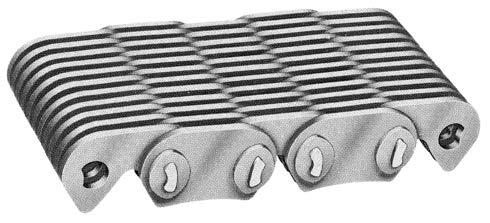
2 HV DRIVE DESIGN WHAT IS HV? HV is a proven transmission drive with a design and capability entirely unique from the usual chain drive which combines the smoothness of a belt drive with the strength, compactness, economy, and long service life of a steel chain. The chain assembly is composed of a series of inverted tooth steel links, laced in alternate sections across the width of the chain. It is assembled with two steel pins having the same cross-section geometry, one called the pin and the other the rocker, which form the articulating link joint between the link sections. See page H-8 for chain dimensions. / 2 and 2 inch Pitches / 8, / 2, / 4 and inch Pitches HV LINK The link design in the original HV pitches - / 4,, / 2 and 2 inch (Fig. ) has been tested in practice and proven for many years. The link crotch is located slightly above the line of pull and all corners are rounded to minimize the possibility of stress risers and to help provide maximum performance on high load industrial application. With the introduction of / 8 and / 2 inch pitch chains (Fig. 2). Morse engineers developed a new link contour for increased speed requirements. This design for the two smaller pitches locates the link crotch below the line of pull. Photo-elastic studies of various link shapes and aperture positions produced the design with the lowest level of stress concentration. In addition, other research studies provided the results for proper metallurgy, toe length, back height, and pressure angle to achieve maximum load carrying capacity and high speed performance. Carefully controlled shot-peening of the links gives them a uniform, matte gray finish and results in the highest level of link fatigue resistance. Another reason for the HV high load performance. Fig. / 2 and 2 inch Pitches H-2 Fig. 2 / 8, / 2, / 4 and inch Pitches


.")
 and the pitch of the chain elongates.")


3 HV DRIVE DESIGN CONCENTRIC PIN AND ROCKER JOINT The concentric pin and rocker joint is used in all pitches of HV chain. This joint (Fig. ) in combination with the involute sprocket tooth design reduces chordal action to a minimum. The HV chain joint consists of a pin and rocker, each with identical cross-sections and concentric radii. In the process of the chain engaging sprocket teeth, the curved surfaces roll on one another thus reducing sliding friction and joint galling. Before the chain engages the sprocket teeth, the contact point of the HV pin and rocker remains below the pitch line (Fig. 4). As the chain engages the sprocket teeth, the contact point moves upward (Fig. 5) and the pitch of the chain elongates. The actual amount of pitch elongation is that required for the chain to wrap the sprocket along the pitch line. Fig. HV SPROCKETS The third criteria for the success of HV is the mating sprockets which complete the drive. The involute tooth form differing from the straight sided teeth of conventional silent chain sprockets is designed for smooth engagement of the chain with the sprocket teeth. All HV sprockets are tophobbed and the teeth heat treated for tough wear resistant surfaces. Unlike the single tooth engagement of spur gears, many teeth share the load of a HV drive. This load sharing of the sprocket teeth results in low stresses, less wear, and long sprocket life. Fig. 4 Fig. 5 CHORDAL ACTION The compatible design of HV links, joints, and sprockets reduces the detrimental effects of chordal action to a minimum, the chordal action of conventional chain drives is the vibratory motion caused by the rise and fall of the chain as it engages sprocket teeth. This motion causes vibration and limits high speed load carrying capability. Of all types of chains, HV operates most efficiently at all speeds because chordal action is reduced to a minimum. Figure 6 shows how the HV chain enters approximately tangent to the pitch circle of the sprocket and maintains this position as it travels around the sprocket. This smooth HV engagement permits high speed capabilities with maximum efficiency and quietness. H-
4 HV DRIVE ADVANTAGES YOU GET MORE WITH HV! The HV Drive link design, compensating pin and rocker joint and the involute hobbed sprockets add up to.. HIGH SPEED PERFORMANCE Normal operating range from,000 to 7,000 FPM with higher speed capability under special conditions. DESIGN FEATURES HIGH HORSEPOWER IN A NARROW WIDTH HV Drive transmits more horsepower per width than any other chain or belt with range from low to several thousand horsepower. SMOOTH PERFORMANCE The rolling action of chain joints and smooth chain-sprocket engagement does not induce vibrations. HIGH EFFICIENCY Up to 99.7% efficiency means power loss is minimal. QUIET-NOISELESS OPERATION The HV Drive operates much quieter on high speed applications than that of traditional chain drive or timing belt drives. High Speed Performance High Horsepower Small Space Smooth Quiet SEVEN good reasons to use HV Drive in your design! When gear trains of two or more meshes are needed to achieve center distance requirements-hv transfer cases provide weight and cost savings because:. FEWER SHAFTS and Bearings are required. 2. LIGHTER LOADS on Shaft Bearings.. CHAIN BEARING LOADS are compressive, placing case in compression. Gear forces are outward subjecting case to more stress. 4. ELASTICITY OF HV CHAIN accommodates normal thermal expansion, which helps "cushion" the drive. 5. CENTER DISTANCE IS LESS CRITICAL and more flexible than required by gear mesh 6. HV CASES ARE LIGHTER and the 7. SIMPLIFIED DESIGN results in a positive cost saving. / 8, / 2, / 4 and inch Pitches H-4
5 HV DRIVE COMPARISONS POWER COMPARISON WITH OTHER DRIVES The comparative rating curves show graphically the area of HV superiority over other types of chain and positive drive belts. The shaded area indicates that the capacity of HV far surpasses that of other power transmission drives because of its... LOAD CARRYING CAPACITY SMOOTHNESS HIGH SPEED PERFORMANCE QUIETNESS HORSEPOWER CAPACITY - COMPARABLE DRIVES HV Chain A /2 Pitch, 5/8 Wide HORSEPOWER PER INCH OF WIDTH HV EXCLUSIVE C Silent Chain (Morse Silent Chain) /2 Pitch, 5/8 Wide Timing Belt (RMA) D /2 Pitch, 5/8 Wide B #40 Roller Chain (ANSI) /2 Pitch, One Strand DRIVE SPEED FEET PER MINUTE ANSI American National Standards Institute RMA Rubber Manufacturers Association Consider the comparisons below. Higher and lower ratings and/or speed capabilities are possible with other pitches and widths Chain or Belt from Above Graph Peak HP Peak feet/ Minute horsepower Per $ Quiteness Smoothness Flexibility Compactness A (HV) 2 6,675 # # # # # B (Roller Chain) 0,225 # 2 # # # # 2 C (Silent Chain) 50 5,20 # # 2 # 2 # # D (Timing Belt) 4 7,768 # 4 # 2 # 2 # 2 # 4 H-5


6 HV DRIVE APPLICATIONS PACKAGE HV DRIVES Photographs below and on the following page are examples of HV packaged drives, custom designed to meet particular space, speed and load requirements. HV packaged drives offer the designer... DESIGN SIMPLICITY QUIET OPERATION CASE COMPACTNESS HIGH SPEED CAPABILITY CENTER DISTANCE FLEXIBILITY SMOOTH POWER TRANSFER CENTRIFUGAL BLOWER DRIVE Power from a 25 HP, 500 RPM electric motor is transmitted through a HV transfer case with self-contained lubrication system to a centrifugal blower at 00 RPM over a 4 inch horizontal center distance. This drive operates 24 hours a day to provide smooth,quiet, maintenance free operation in a critical power plant application. HIGHWAY SNOW BLOWER DRIVE Power from an auxiliary 465 HP rear of cab mounted diesel engine is directed downward through a two stage HV reduction unit with 4.85 to total ratio to enable a drive shaft to pass forward under the cab to a snow auger and blower assembly. The characteristics of HV drives are particularly suited to this application because of their ability to transmit power smoothly in a minimum of space and absorb the heavy shocks encountered in highway snow removal. CENTRIFUGAL COMPRESSOR DRIVE Power from a 200 RPM natural gas engine is transmitted continuously thru a HV speed increaser with an integral lubrication system. The output of the case drives a centrifugal compressor absorbing 282 HP at 600 RPM. A Morse radial coupling connection on the input side of the case dampens engine torsional vibrations. The HV drive is quiet, highly efficient and allows for convenient layout of engine and compressor. H-6


7 HV DRIVE APPLICATIONS PACKAGE HV DRIVES FIRE TRUCK-PUMP DRIVE Power from V-8 engine is transmitted through a pair of HV packaged drives to provide full torque power take-off at a.24 to reduction ratio for driving discharge water pumps. HV drive was selected because of low noise level, compact design, and high efficiency. SWAMP BOAT DRIVE The output from a 45 HP air-cooled gasoline engine is reduced from 4400 RPM to 2750 RPM to drive the propeller of a low draft swamp boat. This application of a HV chain case resulted in increased propulsive efficiency through the use of a larger diameter, slower turning propeller which also contributed to reduced operating noise level. TEST STAND DRIVE The combined power from two 500 HP automotive V-8 engines is transmitted thru a dual ratio HV drive to a single output shaft which drives a cable winch propelling full-sized passenger cars into a fixed barrier for crash evaluation and testing. Flexibility of HV case design provided the specific ratios in the center distance and space requirements. RECREATIONAL VEHICLE This HV transfer case drives the wheels of a 7-ton recreational vehicle. Power from a 454 cubic inch engine, thru a torque converter and a speed transmission is transmitted by a Morse HV transfer case with 70 Ibs. ft. max. torque at 2800 RPM. This HV drive was used because it offered the RV industry maximum space utilization while still satisfying heavy load requirements. DREDGE PUMP DRIVE A pair of 25 HP diesel engines are connected to input shafts of HV packaged drive. The dual 2.7 to reduction ratio provides power to a single output shaft at 460 RPM to rotate a 66 inch diameter pump impeller. The HV drive was custom designed to meet limited space requirements. H-7


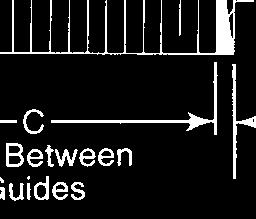
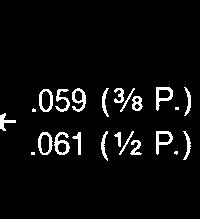
8 HV DRIVE DIMENSIONS MORSE HV DRIVE DIMENSIONS Press Fit Guide Links Type 6-9 Press Fit Guide Links Type 6-5 / 8, / 2, / 4 AND / 2 AND 2 INCH PITCH HV CHAIN PITCH INCHES * A INCHES HEIGHT OF CHAIN B INCHES /8.69 ± ±.002 /2.225 ± ±.002 /4.87 ± ± ± ±.004 *A = Height of chain above Nominal Pitch Diameter of Sprocket CHAIN PITCH INCHES *A INCHES HEIGHT OF CHAIN B INCHES /2.80 ± ± ± ±.007 / 8 AND / 2 INCH PITCH HV CHAINS / 4, / 2 AND 2 INCH PITCH HV CHAINS H-8 CHAIN NOMINAL WIDTH INCHES C D E / / CHAIN PITCH INCHES *WIDTH FOR FIRST INCH C D E / / * For widths greater than in. add width desired minus in. to above dimensions. Example: /4 pitch, 2 inch wide, the width between guides is.750 inches.
9 HV DRIVE SELECTION HV CHAIN () HV CHAIN DESIGNATION (2) NOMINAL WIDTH INCHES AVERAGE ULTIMATE TENSILE STENGTH IN POUNDS AVERAGE WT. PER FOOT IN POUNDS () HV CHAIN DESIGNATION (2) NOMINAL WIDTH INCHES AVERAGE ULTIMATE TENSILE STRENGTH IN POUNDS AVERAGE WT. PER FOOT IN POUNDS /8 INCH PITCH HV-0 /4 5, HV-04 7, HV-06 /2,250.0 HV ,000.7 HV-2 22, /2 INCH PITCH HV-404 0,000.5 HV-406 /2 5,000.7 HV , HV-42 0, HV , INCH PITCH HV , HV-82 60, HV , HV , HV , /2 INCH PITCH HV-22 90, HV , HV , HV , /4 INCH PITCH HV-606 /2 22, HV , HV-62 45, HV , HV , INCH PITCH HV , HV , HV , HV , () Above chain sizes are stock in 0 ft. boxes. Each stock (0 ft.) and cut-to-length chains are supplied with one connecting pin set. Offset sections are not available. (2) Widths other than listed are available for special, approved applications. HV DRIVE SELECTION. Determine the R.P.M. and diameter of the high speed shaft. 2. Determine the total horsepower to be transmitted.. Determine proper service factor from table on page H Establish Design Horsepower by multiplying total horsepower to be transmitted by the proper service factor. 5. Select the chain pitch and width and number of teeth in the small sprocket from the Horsepower Rating Tables. a. Be sure the small sprocket will accommodate the high speed shaft diameter. b. If the high speed shaft diameter exceeds the maximum bore in the selected small sprocket it will be necessary either to increase the number of teeth in the sprocket or select the next larger pitch chain. 6. Determine the required ratio: RPM high speed shaft = Ratio RPM slow speed shaft 7. Multiply the number of teeth in the small sprocket by the ratio to obtain the number of teeth in the large sprocket. 8. Turn to page H- to calculate chain length. HV drives use modified center distances to compensate for chain and sprocket tolerance as determined on page H-8. CAUTION: RELATIVE TO APPLICATIONS INVOLVING THE HANDLING OF PEOPLE, CONTACT APPLICATION ENGINEERING AT MUST BE CONSULTED PRIOR TO DRIVE SELECTION. H-9
10 HV DRIVE SELECTION SERVICE FACTORS The Horsepower rating tables (pages H-2 and H-) are for use under optimum drive conditions with a smooth power source and load. For less favorable conditions with moderate or heavy shock loads from either the power source and/or the load, the specified horsepower must be multiplied by a "Service Factor" (SF) to obtain a "Design Horsepower" (DHP). The "Design Horsepower" is used to obtain the chain selection from the rating tables. Recommendations are minimum and normal conditions are assumed. PRIME MOVER Internal Combustion Engine with Hydraulic Coupling or Torque Converter Electric Motor Turbine Hydraulic Motor Internal Combustion Engine with Mechanical Drive TYPE A B SERVICE FACTOR TABLE APPLICATION TYPE OF PRIME MOVER APPLICATION TYPE OF PRIME MOVER APPLICATION TYPE OF PRIME MOVER A B A B A B AGITATORS CRUSHING MACHINERY PAPER INDUSTRY MACHINERY (paddle or propeller) Ball mills, crushing rolls, jaw Agitators, bleachers.. Pure liquid.. crushers.6.8 Barker-mechanical.6.8 Liquids - variable density.2.4 DREDGES Beater, Yankee Dryer..5 BAKER MACHINERY Conveyors, cable reels.4.6 Calendars, Dryer & Paper Dough Mixer.2 - Jigs & screens.6.8 Machines.2.4 BLOWERS SEE FANS CONSULT Chippers & winder drums.5.7 BREWING & DISTILLING Cutter head drives MORSE PRINTING MACHINERY EQUIPMENT Dredge pumps SEE PUMPS Embossing & flat bed presses, Bottling Machinery.0 - FANS & BLOWERS folders.2 - Brew Kettles, cookers, mash Centrifugal, propeller, vane..5 Paper cutter, rotary press & tubs.0 - Positive blowers (lobe).5.7 linotype machine. - Scale Hopper-Frequent starts.2 - GRAIN MILL MACHINERY Magazine & newspaper BRICK & CLAY EQUIPMENT Sifters, purifiers, separators.. presses.5 - Auger nachines, cutting table..5 Grinders and hammer mills.2.4 PUMPS Brick machines, dry press, & Roller mills..5 Centrifugal, gear, lobe & vane.2.4 granulator.4.6 GENERATORS & EXCITERS.2.4 Dredge.6.8 Mixer, pug mill, & rolls.4.6 MACHINE TOOLS Pipe line.4.6 CENTRIFUGES.4.6 Grinders, lathes, drill press.0 - Reciprocating COMPRESSORS Boring mills, milling machines. - or more cyl...5 Centrifugal & rotary (lobe).. CONSULT or 2 cyl..6.8 MARINE DRIVES Reciprocating MORSE RUBBER & PLASTICS or 2 cyl..6.8 MILLS INDUSTRY EQUIPMENT or more..5 Rotary type: Calendar, rolls, tubers CONSTRUCTION EQUIPMENT Ball, Pebble, Rod, Tube, Roller.5.7 Tire-building and OR OFF-HIGHWAY VEHICLES Dryers, Kilns, & tumbling Banbury Mills.5.7 Drive line duty, power barrels.6.8 Mixers and sheeters.6.8 take-off, accessory CONSULT Metal Type: Extruders.5.7 drives MORSE Draw bench carriage & main SCREENS CONVEYOR drive.5 - Conical & revolving.2.4 Apron, bucket, pan & elevator.4.6 CONSULT Rotary, gravel, stone & Forming Machines Belt (ore, coal, sand, salt).2.4 MORSE vibrating.5.7 Belt-light package, oven.0.2 MIXERS STOKERS. - Screw & flight (heavy duty).6.8 Concrete.6.8 TEST STANDS & CONSULT CRANES & HOISTS Liquid & Semi-liquid.. DYNAMOMETERS MORSE Main hoist-medium duty.2.4 OIL INDUSTRY MACHINERY TEXTILE INDUSTRY Main hoist-heavy duty, skip Compounding Units.. Spinning frames, twisters, hoist.4.6 Pipe line pumps.4.6 wrappers & reels.0 - Slush pumps.5.7 Batchers, calendars & looms. - Draw works Chillers, Paraffin filter presses, Kilns.5.7 H-0
11 HV DRIVE SELECTION CHAIN LENGTH CALCULATIONS Determine the chain length based on a given center distance and sprocket teeth as follows:. Divide the center distance in inches by pitch of chain obtaining C 2. Add teeth in the small sprocket (n) to the teeth in the larger sprocket (N) obtaining S. Subtract the teeth in the small sprocket (n) from the teeth in the large sprocket (N) obtaining value of D From the table below obtain the corresponding value of K S K Chain length in pitches (L) = 2C C Chain length must be determined to the nearest even number of pitches. Center distance will have to be recalculated (step 6). 4. Chain length in feet equals the chain length in pitches times the pitch in inches divided by After finding the chain length to the nearest number of even pitches from Step 4, the nominal center distance must be determined to three decimal places. Center distance tables should be used or contact Morse for this value of nominal center distance. The above formula for determining chain length cannot be used to solve for correct center distance. 6. With fixed center distance drives the modified center distance is determined as noted on Page I-8. Example Given: N = 60, n = 25, P = /2 inch. Center Distance (CD) = 24 inches Determine: (a) chain length (L) to nearest even number of pitches (b) determine the center distance based on actual number of pitches (L). Solution: () C = 24" /2 = 48 (2) S = (25 +60) = 85 () D = (60-25) = 5 corresponding K =.0 (4) L = (2 X 48) L = = 40 pitches (nearest even number) (5) L (in feet) = 5.8 feet (40 x / 2 2). (6) Nominal center distance must be obtained from center distance tables and in this instance CD in inches = If center distance tables are not in your possession please contact Morse for correct CD calculation. D K D K D K D K D K D K Note: (Relating to service factor) Recommendations are minimum and normal conditions are assumed. H-
12 HV CHAIN HORSEPOWER RATING MORSE HV CHAIN HORSEPOWER RATING TABLES Preliminary drive selection of chain and sprockets may be obtained from the tables below. However, Morse suggests that all HV drive Selections be submitted to our Engineering Department for final confirmation. Since more than one pitch will work well in most situations it may be desirable to make two or three choices and base final selection on the features most important in the design such as cost, stock chain and sprocket availability, size of drive, noise level (small pitches are quieter), loading (larger pitches carry greater load), and smoothness. / 8 INCH PITCH HP PER INCH OF WIDTH BASED ON NO. OF IN SMALL SPROCKET RPM / 2 INCH PITCH HP PER INCH OF WIDTH BASED ON NO. OF IN SMALL SPROCKET RPM / 4 INCH PITCH HP PER INCH OF WIDTH BASED ON NO. OF IN SMALL SPROCKET RPM For best drive performance, use 25 teeth or more on small sprocket. Forced pump lubrication is recommended. Bath lubrication is satisfactory for applications to the left of the heavy line. For HP values at higher speeds than shown, consult Technical Services. H-2
13 HV CHAIN HORSEPOWER RATING MORSE HV CHAIN HORSEPOWER RATING TABLES (CONTINUED) INCH PITCH HP PER INCH OF WIDTH BASED ON OF IN SMALL SPROCKET RPM / 2 INCH PITCH HP PER INCH OF WIDTH BASED ON OF IN SMALL SPROCKET RPM INCH PITCH HP PER INCH OF WIDTH BASED ON OF IN SMALL SPROCKET RPM For best drive performance, use 25 teeth or more on small sprocket. Forced pump lubrication is recommended. Bath lubrication is satisfactory for applications to the left of the heavy line. For HP values at higher speeds than shown, consult Technical Services. H-


14 HV CHAIN SPECIFICATIONS HV SPROCKET INFORMATION BASIC HUB TYPES Sprockets Are made for stock and Manufactured to order in accordance with Morse specifications. Are Hobbed with a generated involute tooth form. Have Hardened Teeth for wear resistance on tooth flanks. Materials Sprockets up to 5 inches diameter are usually made from bar steel with larger sprockets manufactured from plate steel, forged slugs, Meehanite or steel castings. The type of material can vary depending upon requirements for delivery, quantity, sprocket design, and price. For example: Sprockets over 5 inches diameter can be made from meehanite or steel castings but, require somewhat longer manufacturing lead times for procurement of castings; if made of fabricated steel with welded hubs, shorter manufacturing lead times are realized but, the cost may be higher. TYPE A Flush with face of sprocket Dimensions Nominal pitch and outside diameters-pages H-5 and H-6. Maximum bores and hub diameters for sprocket sizes from 2 through teeth. Face width dimensions. Tolerances Bore diameters, keyseats and concentricity. Tolerances closer than shown can be furnished if required. The need for closer tolerances should be carefully considered in light of increased costs. Installation of sprockets TYPE B Hub one side Performance information For maximum drive performance it is recommended that a minimum of 25 teeth be used in the small sprocket. However, it is permissible to use a minimum of 9 teeth in the small sprocket with reduced performance. Where drive design is under 25 teeth-consult Morse. For most drives, an odd number of teeth in one of the sprockets is recommended. The use of idler sprockets is not recommended in HV drives. Drives employing more than two sprockets per chain should be referred to Morse for review. TYPE C Hub located centrally with projection both sides or hub can be the same length as sprocket face or offset as required. HV sprocket ordering information Specify number of teeth, pitch, chain width or sprocket face, hub, type (if required). Unless specified, the length thru bore (LTB), hub diameter (HD), keyway, setscrew and tolerances will be to Morse standard specifications. Material of sprockets and tooth hardness will be to Morse standard specifications. H-4

15 HV CHAIN CHAIN / 8 " PITCH HV SPROCKETS / 8 " pitch / 4 " FACE WIDTH CATALOG PITCH DIA. (in.) MIN. PLAIN MAX. HD LTB APPROX. WT. 9 HV0B /2 5 /2 5 /8 /2.9 2 HV0B /2 9 /2 7 /8 /2.2 2 HV0B /2 /8 2 /8 / HV0B /4 5 /8 2 /8 / HV0B27.20 /4 /4 2 5 /8 / HV0B /4 /6 2 7 /8 /2 2.6 HV0B.707 /4 2 /8 /2 /2. 8 HV0B /4 2 7 /8 5 /6 / HV0B /4 5 /6 4 /2 / HV0B /4 4 /2 6 / HV0B /4 4 /2 6 /2 6.7 " FACE WIDTH 9 HV04B /2 5 /2 5 /8 5 /8. 2 HV04B /2 9 /2 7 /8 5 /8.4 2 HV04B /2 /8 2 /8 5 / HV04B /4 5 /8 2 /8 5 / HV04B27.20 /4 /4 2 5 /8 5 / HV04B /4 /6 2 7 /8 5 /8. HV04B.707 /4 2 /8 /2 5 /8.6 8 HV04B /4 2 7 /8 5 /6 5 / HV04B /4 5 /6 4 /2 5 / HV04B /4 4 /2 6 5 / HV04B /4 4 /2 6 5 / / 2 " FACE WIDTH 9 HV06B /2 5 /2 5 /8 2 5 /2.5 2 HV06B /2 9 /2 7 /8 2 5 /2.9 2 HV06B /2 /8 2 /8 2 5 / HV06B /4 5 /8 2 /8 2 5 /2 2.8 TYPE B Teeth Hardened Hub Projection One Side 27 HV06B27.20 /4 /4 2 5 /8 2 5 / HV06B /4 /6 2 7 /8 2 5 /2 4. HV06B.707 /4 2 /8 /2 2 5 / HV06B /4 2 7 /8 5 /6 2 5 / HV06B /4 5 /6 4 /2 2 5 / HV06B /4 4 / / HV06B /4 4 / / H-5


16 HV CHAIN CHAIN / 2 " PITCH HV SPROCKETS / 2 " pitch " FACE WIDTH CATALOG PITCH DIA. MIN. PLAIN MAX. APPROX. HD LTB (in.) WT. 9 HV404B9.08 /2 7 /6 2 7 / HV404B2.55 /2 /6 2 / HV404B2.672 /4 /6 2 7 / HV404B /4 2 /8 / HV404B /4 2 /8 / HV404B /4 2 9 /6 / HV404B /4 2 /4 4 5 /2 2 / HV404B /4 /4 5 9 /2 2 / HV404B /4 4 /8 5 5 /6 2 / HV404B /4 4 /2 6 2 / HV404B /2 5 /8 2. / 2 " FACE WIDTH 9 HV406B9.08 /2 7 /6 2 7 /2 2 /2. 2 HV406B2.55 /2 /6 2 /2 2 / HV406B2.672 /4 /6 2 7 /8 2 / HV406B /4 2 /8 /6 2 / HV406B /4 2 /8 /2 2 / HV406B /4 2 9 /6 /6 2 /2 9.0 HV406B /4 2 /4 4 5 / HV406B /4 /4 5 9 /2 9.7 LTB TYPE B Teeth Hardened Hub Projection One Side 42 HV406B /4 4 /8 5 5 / HV406B /4 4 / HV406B /2 5 /8 2 / " FACE WIDTH 9 HV408B9.08 /2 7 /6 2 7 / HV408B2.55 /2 /6 2 / HV408B2.672 /4 /6 2 7 / HV408B /4 2 /8 / HV408B /4 2 /8 / HV408B /4 2 9 /6 /6 0.9 HV408B /4 2 /4 4 5 / HV408B /4 /4 5 9 / HV408B /4 4 /8 5 5 / HV408B /4 4 /2 6 / HV408B /2 5 / " FACE WIDTH 9 HV42B9.08 /4 7 /6 2 7 / HV42B2.55 /4 /6 2 / HV42B2.672 /4 /6 2 7 / HV42B /4 2 /8 / HV42B /4 2 /8 / HV42B /4 2 9 /6 / HV42B /4 2 /4 4 5 / HV42B /4 /4 5 9 / HV42B /4 4 /8 5 5 / HV42B /4 4 /2 6 4 / HV42B /2 5 / H-6

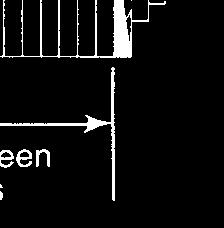
17 HV CHAIN DRIVES INSTALLATION MORSE HV CHAIN DRIVE INSTALLATION INFORMATION HV chain and sprocket Installation - When cases for HV drives are not purchased from Regal and the design and manufacture is performed by others, certain basic guidelines must be followed to ensure proper drive performance. Morse HV drive recommendations, ratings, and selection procedures in this catalog are premised on installation in a proper housing with alignment and installation as outlined in this section and lubrication as recommended on pages H-9 and H-20. A. Case Structures Morse HV drives are normally employed on applications where high speed and/or high horsepower transmission is the requirement. The HV drive should be installed in rigid housings of welded steel or cast construction complete with shafts, bearings, seals, and a proper lubrication system in order to realize the full performance capability of the drive (Fig. ). The connection or interface to driver and driven equipment is accomplished by flexible couplings, universal joints, or direct flanges. Morse offers the service of design and manufacture of such cases. C. Sprocket Offset Offset from the machined face of one sprocket to the corresponding face of the second sprocket (Fig. ) should ideally be held to zero with the maximum permissible offset limited to the value "K" inches in table below. Excessive offset will cause wear on inside of guide links or possible chain failure if the chain guides climb the sprocket teeth. CHAIN PITCH INCHES / 8 / 2 / 4 / 2 2 K B. Shaft Parallelism Shafts must be parallel in two planes within.005 inch/foot of bearing 'mounting distance (Fig. 2). Special attention must be given to drives with non-horizontal shafts due to the tendency for chain to ride on the guide links. Applications with shafts other than the horizontal should be referred to Regal. D. Sprocket Mounting Sprockets should have a light interference fit on shafts. Preferred fits can be obtained from the latest ANSI Standard B4. for Interference Locational Fits, Class LN. Sprockets may be installed by heating the sprocket in 80 F oil, shrinking the shaft with dry ice or press-fitting with a hydraulic press. A positive mechanical connection is necessary for torque transmittal regardless of the type of sprocket fit to shaft. Sprockets with tapered bores or keyseats are satisfactory, however, Morse does not recommend the use of split-tapered bushings in mounting HV sprockets to shafts. It is recommended that each sprocket be located positively against a shoulder or step on the shaft for accurate positioning. With this style mounting, the use of type "A" (hubs flush) sprocket will provide the simplest design. E. HV Chain Installation HV chains can be furnished in the number of required pitches endless or open for connection of the ends with a standard pin set. In some case designs, bearing carriers are large enough to install sprockets and endless chain through the openings. Other designs employ housings which are split at the shaft center to facilitate installation. If chain must be installed open refer to Figs. thru 5 on page H-8. H-7


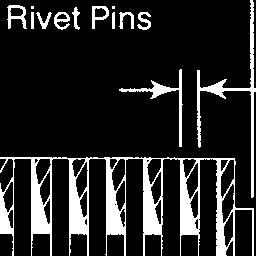
18 HV DRIVES INSTALLATION MORSE HV CHAIN DRIVE INSTALLATION INFORMATION (CONTINUED) Bring ends of chain together,on top of larger sprocket in mesh with sprocket teeth. On pre-loaded, fixed center distance a hook-up tool similar to that shown may be used to bring the ends together. Center distance tables should be used or contact Regal for this value. HV center distances are modified to compensate for chain and sprocket tolerances. This modified center distance is obtained by adding.008 inch per foot of center distance to the nominal or theoretical flat pitch center distance. Center distance tolerance should be on the plus side. G. HV Case Clearances Radial Clearance - Where the chain fully wraps the sprockets, the desirable radial clearance beyond the pitch circle is 2 times the chain pitch. Minimum clearance sufficient to clear the chain in process of jumping a sprocket tooth is / 8 times the pitch. When connecting the open ends with a pin set, it is very important that the longer pin of the set must seat nearest to the outside flank of the guide plate. For rivet type connectors: washers are used on both sides in chain pitches of / 2 and 2 inches. Washers are not used in chain pitches of / 8, / 2, / 8 and inches. Sag Clearance - The case must be designed for clearance between the slack strand of chain and the inside of the case. For this clearance, use the formula below with value of "A" determined from graph (Fig. 6). For reversing drives, design with sag clearance both top and bottom. 50 Sag Clearance (inches) =A x Tangent Distance (inches) 00 Spirol pin type connectors are normally used for connecting open ended chains. Spirol Pin is driven into each end of pin with a drift. F. Center Distance On large drive ratios (over :) it is desirable to have at least 20 degrees wrap on the small sprocket. On drives without center distance adjustment the center distance should be kept to a minimum. Minimum center distance is limited to half the sum of the pitch diameters. It is desirable to keep the center distance under 0 pitches. Drives with long center distances may require center distance adjustment to attain adequate wear life. Adjustable center distances should be limited to a maximum of 60 pitches of chain, and if a longer center distance is required a double reduction may be necessary. Center distance and sprocket combinations must always be selected to provide an even number of chain pitches. Nominal center distances should be calculated to three decimal places. H-8 A = Sag Clearance of Tangent Distance Tangent Distance in Pitches Side Clearance - The side clearance beyond the width of the chain should be equal to or greater than one chain pitch.

19 HV DRIVES LUBRICATION HV CHAIN LUBRICATION A. Pressure Lube Systems Experience has shown that for chain speeds above 2500 FPM a pressure lubrication system is required. Proper lubrication is necessary to help provide satisfactory performance, chain wear life and to also lubricate the surfaces of chain and sprocket contact. The lubricant must penetrate the chain joints to dissipate frictional heat and flush out foreign particles. A replaceable element full flow oil filter with built in relief valve should be installed between the oil pump and spray pipe. The filter element should be capable of removing particles larger than 25 microns. A pressure gauge or a low oil pressure switch with a warning device or light is recommended to protect the chain drive in the event of a malfunction in the lube system. Additional components should include an oil sump strainer for the oil pump suction line, and oil fill/breather, magnetic drain plug and an oil level sight gauge. Shaft bearings can be lubricated from the oil spray within the case or in some instances, separate lube lines may be required. B. Bath Lubrication At chain speeds below 2500 FPM bath lubrication may be satisfactory. With bath lubrication, the dynamic oil level should be maintained at the lowest point of the pitch line, and for this purpose an oil level sight gauge is desirable. Too low an oil level is ineffective and too high a level will cause detrimental churning and heating of the oil. In some instances it may be necessary to provide baffles and troughs to direct oil into the chain. In some cases bearings may require separate lubrication. Fig. Pressure (Pump) Lubrication The lubrication system should supply filtered oil under pressure to the spray pipes at the total rate of GPM per inch of chain width. The lubricating pump with integral pressure relief valve can be driven directly from one of the case shafts or by means of a separate motor, or an existing supply of lubricating oil under pressure may be utilized. When utilizing a case driven oil pump, the oil reservoir or sump should have a minimum capacity of three minutes of oil flow. Spray pipes having / 8" I.D. with one.09 inch diameter orifice per inch of chain width are adequate for most installations. Long center distances or reversing drives may require an additional spray pipe. (A single.09 inch diameter orifice flows approximately.8 GPM of SAE 20W oil at 20 PSI.) The spray pipe is located so as to spray oil into and thru the chain as the slack strand enteres the sprocket (Fig. 2). Fig. Bath Lubrication C. Lubrication Oil Specifications Satisfactory HV chain case performance depends upon the use of well refined, high quality oil. As a guide to lubrication products, oils are designated by the letters SA, SB, and SC on the containers. These letters are service classifications established by the American Petroleum Institute (API). The designations are in addition to the SAE grades established by the Society of Automotive Engineers which indicate the viscosity of the oil recommended H-9
. Oils that do not have both the SAE viscosity and recommended API designations on the container should not be used.")
20 HV DRIVES MAINTENANCE MAINTENANCE For maximum performance use an oil conforming to one of the API classifications (Page H-9) with the proper SAE Grade number in accordance with the anticipated operating temperature (See chart below). Oils that do not have both the SAE viscosity and recommended API designations on the container should not be used. OIL VISCOSITY RECOMMENDATIONS SURROUNDING OR AMBIENT TEMP. VISCOSITY SAE GRADE VISCOSITY SAYBOLT 00 F Under 40 F *SAE 5 50 SSU 40 to 90 F *SAE SSU Over 90 F *SAE SSU *Type A or B Automatic Transmission Fluid (ATF) can also be used. Where Application Requires Oil in Excess of SAE 20 Grade, Consult Morse Engineering for Recommendations. It is desirable to limit lube oil sump temperature to 80 F maximum to help prevent rapid deterioration of the oil. This can be accomplished by external cooling fans or a suitable oil cooler if necessary. Generally HV chains operate with a temperature rise of approximately 40 F above ambient temperature. If an oil cooler is installed as a part of the lubrication system, the SAE grade and equivalent viscosity (SSU) for the next lower ambient temperature range can be used. For example: If ambient room temperature is 95 F and oil cooler is not used, an SAE 20 oil F with API service classification SA, SB, or SC should be used. If an oil cooler is provided an SAE 0, F oil, Type A or B Automatic Transmission Fluid (ATF) can be used. Lubrication Changes Oil should be kept clean to help assure long, trouble free service. If oil becomes dirty or discolored or otherwise appears to be contaminated, it should be drained, flushed and replaced. Good practice dictates that periodic oil changes should be made with the proper SAE viscosity and API classification every 000 hours or every 4 months whichever occurs first. If Type A Automatic Transmission Fluid is used, it should be changed if the characteristic red coloring becomes a brownish color indicating oxidation in the oil. When oil is changed, the case should be drained, flushed with a suitable solvent (Mobil Oil Company*, Solvasol* or equivalent), and replaced with a new oil. The unit must be kept free of water and foreign material at all times. If water is found in the oil, more frequent oil changes may be required. Conversely, longer oil change intervals are possible if operating conditions are such that the oil does not deteriorate or become contaminated. The length of oil change intervals should be ascertained after a careful analysis of operating conditions and inspections of the oil. When making oil changes a thorough inspection of the lube system piping, pump, and spray pipe orifices should be made. The filter element should be replaced at this time if it is dirty. A good functioning oil system with clean oil of the correct type is necessary for long, quiet trouble free life of the HV drive and case. HV transfer case This HV transfer case is directly mounted on the tail shaft extension of an automatic transmission directing power to both front and rear axles of a cargo vehicle. The HV case has a.09: reduction ratio and transmits up to 400 lb.-ft. torque at stall and RPM with maximum chain speed of 6200 FPM. The lower weight of the HV case over comparable gear type case allowed increased vehicle payload. Photograph below is an example of HV transfer case, custom designed to meet customer's requirements * Mobil and Solvasol are believed to be the trademark or trade name of Exxon Mobil Corporation. and are not controlled by Regal Beloit Corporation. H-20

21 SILENT CHAIN DRIVES MORSE SILENT CHAIN DRIVES MORSE SILENT CHAIN provides an economical, compact drive with reduced loads and long life. REGAL is your single source of supply for a full range of SILENT CHAIN DRIVES. All sprockets and chains are available when and where you need them. Available in standard pitches from / 6 " to " and in widths up to 6". H-2


22 SILENT CHAIN DRIVE FEATURES FEATURES 99% Efficient Drives Economical Simple Installation Long Life Space Saver Reduced Bearing Loads Smooth Drive Quiet Drive Cool Drive Not Affected by Atmospheric Conditions Adaptable to Your Centers High Speeds Minimum of Maintenance Adaptable to Speed Changes Positive Drive-No Slip Wide Speed and H.P. Range Morse Silent Chain is an Inverted Tooth type drive offering particularly smooth, quiet power transmission at higher speeds up to 5000 FPM. The exclusive Morse Rocker Joint eliminates friction during chain articulation-permitting high rotative speed with less wear and heat. All of the silent chains and sprockets listed are to the ANSI standard profile. Chain designation listed as example SC 408, indicating: S.C.-Silent Chain standard link profile and guide 4-Pitch in /8" increments 08-Width in /4" increments All sizes of chain and sprockets listed are of the Center Guide type except SC02. Standards are not such that competitive chains may be connected together. They will, however, individually run over the same set of standard sprockets. Sprocket designation listed, as an example, 408-8: 4-Pitch in /8" increments 08-Width in /4" increments 8-Number of teeth Offset link section Adjustments of centers and an even number of pitches in the chain length are desirable characteristics for all chain drives. Centers should be selected which result in an even number of pitches in the chain length. When fixed centers necessitate the use of an odd number of pitches an offset link or hunting link may be used. As illustrated, this assembly, four pitches long, includes one row of offset links. H-22


 AVERAGE ULTIMATE TENSILE IN POUNDS WEIGHT PER FOOT IN POUNDS SC-005 5 /2.200 /2 2 &.08.40.248.096 500.")
23 SILENT CHAIN / 6" PITCH / 6 " PITCH SILENT CHAIN The Morse / 6" pitch silent chain drive is a high speed power transmission medium that offers the maximum in performance and reliability. Quietness and durability are the result of unique design and manufacturing practices. Materials are the finest alloy steels, properly heat treated to resist wear and fatigue. Chain link and sprocket profiles are in accordance with practices established by the chain industry. Morse / 6" Silent Chain is available in non-corrosive types of materials. Morse / 6" pitch Silent Chain is manufactured in three basic types of assembly to give complete coverage for all drive requirements. Eight standard widths handle load ranges and speeds with economy and long chain life. For standard drives, side guide chain is recommended for all chains up to and including 5 / 2" wide (SCO5). For standard drives, center guide is recommended for all chains 9 / 2" (SCO9) and wider. For serpentine drives, reversing secondary shaft rotation, or if adjustable idler is required. Duplex chain will give a rugged positive drive with maximum service. Consult factory for recommendations and assemblies. When cut length is specified pin and plate sets will be furnished at the per foot price. Cotter type joining pin or connecting link are available at an additional price. JOINING PIN Insertion of the pin and cotter allows simple field assembly of the chain. CONNECTING LINK The connecting link is used when chain is cut and assembled in the field. The connecting link consists of pin link, inside link, connector plate and 2 cotter pins. CHAIN NOMINAL WIDTH WIDTH OVER RIVETS A WIDTH BETWEEN GUIDES B ASSEM. LINKS CONNECTING PIN ASSEMBLY WIDTH C D F HEIGHT OF CHAIN ABOVE SPKT. P.D. F (MAX.) AVERAGE ULTIMATE TENSILE IN POUNDS WEIGHT PER FOOT IN POUNDS SC /2.200 /2 2 & SC /2.26 5/2 & SC /2.25 7/2 4 & SC-0 /2.88 9/2 5 & SC-05 5 /2.5 /2 7 & SC-09 9 /2.68 Center Guide 9 & SC /2.825 Center Guide 2 & SC-0 /2.0 Center Guide 5 & Note: Use even number of pitches in chain. Offset or hunting links not available. H-2

 AVERAGE ULTIMATE TENSILE IN POUNDS WEIGHT PER FT. IN POUNDS SC 02* /2.769.")


")
24 SILENT CHAIN DRIVES / 8 ", / 2 " / 4 " & " PITCH STOCK SILENT CHAIN / 8 " PITCH CHAIN CHAIN NOMINAL WIDTH CHAIN WIDTH OVER RIVETS HEIGHT OF CHAIN ABOVE SPKT. P.D. A (MIN.) HEIGHT OF CHAIN B (MAX.) AVERAGE ULTIMATE TENSILE IN POUNDS WEIGHT PER FT. IN POUNDS SC 02* / SC 0 / SC SC 05 / SC 06 / SC / 2 " PITCH SC 40 / SC SC 405 / SC 406 / SC SC 40 2 / SC SC 44 / / 4 " PITCH SC 606 / SC SC60 2 / SC SC SC " PITCH SC SC SC SC *Outside guide type chain. Distance between guides is.460. An offset link is not recommended unless chain needed is an uneven number of pitches. Example: 5 pitches, order 50 pitches and one offset link. An offset or hunting link is assembled without guide links. Price of offset links are added to the per foot price of chain. Stock Chain is supplied with one connecting link set. Additional connecting link sets sold only in package ("Poly-Pack") quantities. Package quantities: (25) for /8" and /2" pitch; (0) for /4" pitch: (5) for " pitch. H-24
25 SILENT CHAIN DRIVES SELECTION Engineering design The following information should be considered to design long life, quiet, trouble free Silent Chain Drives: For long life, a minimum of 7 teeth and an odd number of teeth on one sprocket where possible. For maximum quietness, use sprockets with 2 teeth or more. For trouble free drives, apply service factor for design load. On long or fixed center drives, use a sprocket or shoe idler, placed where greatest amount of slack accumulates. Do not reduce wrap on small sprockets with idler. Engineering is available to you for review of your chain drive design. points to consider in selection There are certain primary conditions which affect the design of efficient silent chain drives. Those most commonly encountered are:. The selection of wider chain than the minimum sizes recommended will give more than a corresponding return in service rendered. This is particularly true in drives where overloads are proportionately high. 2. Quieter drives result from designs employing a larger number of teeth in the drive sprocket. For quieter drives use a minimum of 2 teeth in the driver sprocket.. Larger pitches permit longer center distance. 4. Center adjustment is always desirable. It is necessary with vertical centers. 5. Fully enclosed drives with adequate lubrications are desirable for maximum service life and least maintenance. 6. An even number of pitches in the length of chain is desirable because offset link is eliminated. 7. With horizontal or inclined shaft centers, the tight or pulling strand may be either on the top or bottom when the center distance is equal or less than the sum of the sprocket diameters. For longer centers the tight strand should be on top. 8. Chain drives should be chosen on the basis of Horsepower rating rather than ultimate tensile strength. 9. Chain cases serve as guards for safety and protection. They confine lubrication to the area of the chain proper. selection of silent chain drives. Determine the R.P.M. and diameter of the high speed shaft. 2. Determine the total horsepower to be transmitted.. Determine proper service factor from table. 4. Establish Design Horsepower by multiplying total horsepower to be transmitted by the proper service factor. 5. Select the chain pitch and width and number of teeth in the small sprocket from the Horsepower Rating Tables. 6. a. Be sure the small sprocket will accommodate the high speed shaft diameter. 7. b. If the high speed shaft diameter exceeds the maximum bore in the selected small sprocket it will be necessary either to increase the number of teeth in the sprocket or select the next larger pitch chain. 8. Determine the required ratio: RPM high speed shaft = Ratio RPM slow speed shaft 9. Multiply the number of teeth in the small sprocket by the ratio to obtain the number of teeth in the large sprocket. 0. Turn to page I-2 to calculate chain length. CAUTION: RELATIVE TO APPLICATION INVOLVING THE HANDLING OF PEO- PLE, ENGINEERING MUST BE CONSULTED PRIOR TO DRIVE SELECTION. H-25
26 SILENT CHAIN DRIVES SERVICE FACTORS service factors The Horsepower rating tables (pages I-24 and I- 25) are for use under optimum drive conditions with a smooth power source and load. For less favorable conditions with moderate or heavy shock loads from either the power source and/or the load, the specified horsepower must be multiplied by a "Service Factor" (SF) to obtain a "Design Horsepower" (DHP). The "Design Horsepower" is used to obtain the chain selection from the rating tables. Service Factors are selected below for various applications after first determining the prime mover or power source type. Note: (Relating to Service Factors). Recommendations are minimum and normal conditions are assumed. PRIME MOVER Internal Combustion Engine with Hydraulic Coupling or Torque Converter Electric Motor Turbine Hydraulic Motor Internal Combustion Engine with Mechanical Drive TYPE A B SERVICE FACTOR TABLE APPLICATION TYPE OF PRIME MOVER APPLICATION TYPE OF PRIME MOVER APPLICATION TYPE OF PRIME MOVER A B A B A B AGITATORS CRUSHING MACHINERY PAPER INDUSTRY MACHINERY (paddle or propeller) Ball mills, crushing rolls, jaw Agitators, bleachers.. Pure Liquid.. crushers.6.8 Barker-mechanical.6.8 Liquids-variable density.2.4 DREDGES Beater, Yankee Dryer..5 BAKER MACHINERY Conveyors, pumps, cable reels.4.6 Calendars, Dryer & Paper Dough Mixer.2 - Jigs & screens.6.8 Machines.2.4 BLOWERS SEE FANS CONSULT Chippers & winder drums.5.7 Cutter head drives BREWING & DISTILLING MORSE PRINTING MACHINERY EQUIPMENT Dredge pumps SEE PUMPS Embossing & flat bed presses, Bottling Machinery.0 - FANS & BLOWERS folders.2 - Brew Kettles, cookers, mash Centrifugal, propeller, vane..5 Paper cutter, rotary press & tubs.0 - Positive blowers (lobe).5.7 linotype machine. - Scale Hopper-Frequent starts.2 - GRAIN MILL MACHINERY Magazine & newspaper BRICK & CLAY EQUIPMENT Sifters, purifiers, separators.. presses.5 - Auger machines, cutting table..5 Grinders and hammer mills.2.4 PUMPS Brick machines, dry press, & Roller mills..5 Centrifugal, gear, lobe & vane.2.4 granulator.4.6 GENERATORS & EXCITERS.2.4 Dredge.6.8 Mixer, pug mill, & rolls.4.6 MACHINE TOOLS Pipe line.4.6 CENTRIFUGES.4.6 Grinders, lathes, drill press.0 - Reciprocating COMPRESSORS Boring mills, milling machines. - or more cyl...5 Centrifugal & rotary (lobe).. CONSULT ore 2 cyl..6.8 MARINE DRIVES Reciprocating MORSE RUBBER & PLASTICS or 2 cyl..6.8 MILLS INDUSTRY EQUIPMENT or more..5 Rotary type: Calendars, rolls, tubers CONSTRUCTION EQUIPMENT Ball, Pebble, Rod, Tube, Roller.5.7 Tire-building and OR OFF-HIGHWAY VEHICLES Dryers, Kilns, & tumbling Banbury Mills.5.7 Drive line duty, power barrels.6.8 Mixers and sheeters.6.8 take-off, accessory CONSULT Metal type: Extruders.5.7 drives MORSE Draw bench carriage & main SCREENS CONVEYOR drive.5 - Conical & revolving.2.4 Apron, bucket, pan & elevator.4.6 CONSULT Rotary, gravel, stone & Forming Machines Belt ( ore, coal, sand, salt).2.4 MORSE vibrating.5.7 Belt-light package, oven.0.2 MIXERS STOKERS. - Screw & flight (heavy duty).6.8 Concrete.6.8 TEST STANDS & CONSULT CRANES & HOISTS Liquid & Semi-liquid.. DYNAMOMETERS MORSE Main hoist-medium duty.2.4 OIL INDUSTRY MACHINERY TEXTILE INDUSTRY Main hoist-heavy duty,skip Componding Units.. Spinning frames, twisters, hoist.4.6 Pipe line pumps.4.6 wrappers & reels.0 - Slush pumps.5.7 Batchers, calendars & looms. - Draw works Chillers, Paraffin filter presses, Kilns.5.7 H-26
27 SILENT CHAIN DRIVES CHAIN LENGTH CALCULATION calculation of chain length The following method of calculating approximate chain length may be used for both standard roller chain, silent, and HV drives.. Divide center distance in inches by pitch of chain, obtaining C 2. Add teeth in small sprocket to teeth in large sprocket, obtaining S. Subtract teeth in small sprocket from teeth in large sprocket, obtaining Value D. From table obtain the corresponding value of K S K 4. Chain length in pitches = 2C C 5. Multiply length by pitch of chain to find chain length in inches. Example Given: Teeth in driving sprocket...2t Teeth in driven sprocket...60t Pitch of chain... / 2" Center distance...24" Required: Necessary length of chain Solution: () C = 24" / 2 = 48 (2) S = (2 + 60) = 8 () D = (60-2) = 9 corresponding K = 8.5 (4) Chain length in pitches = (2 X 48) + + = 2 48 The next higher whole number is 8 pitches. (5) 8 X / 2 = 69". A chain cannot contain the fractional part of a pitch; therefore, in case the figure for the number of pitches for the chain length obtained from the use of the above formula contains a fractional part of a pitch, use the next higher whole number of pitches. Whenever possible, use an even number of pitches in the chain length. An odd number of pitches requires the use of an offset link which is not generally desirable. The above formula for calculating chain length cannot be used to calculate center distance dimensions. D K D K D K D K D K D K H-27
28 SILENT CHAIN HORSEPOWER RATING Silent chain horsepower rating tables / 6" PITCH HORSEPOWER PER INCH OF WIDTH OF OF REVOLUTION PER MINUTE-SMALL SPROCKET SMALL SMALL SPROCKET SPROCKET Oil cup or brush lubrication Bath or Splash lubrication Pump lubrication Consult your engineering department for proper method of lubrication Silent chain horsepower rating tables / 8" PITCH HP PER INCH OF WIDTH BASED ON OF IN SMALL SPROCKET RPM Forced pump lubrication is recommended. Bath lubrication is satisfactory for applications to the left of heavy line. For HP values at higher speeds than shown, consult Engineering. H-28
29 SILENT CHAIN HORSEPOWER RATING silent chain horsepower rating tables / 2 INCH PITCH HP PER INCH OF WIDTH BASED ON OF IN SMALL SPROCKET RPM / 4 INCH PITCH HP PER INCH OF WIDTH BASED ON OF IN SMALL SPROCKET RPM INCH PITCH HP PER INCH OF WIDTH BASED ON OF IN SMALL SPROCKET RPM Forced pump lubrication is recommended. Bath lubrication is satisfactory for applications to the left of heavy line. For HP values at higher speeds than shown, consult Engineering. H-29


30 SILENT CHAIN SPROCKETS / 6 " PITCH / 6 " pitch drives OF MAX. HUB DIAMETER MAX. OF MAX. HUB DIAMETER MAX. OF MAX. HUB DIAMETER MAX..45 / / / / / / / / / / / /6.60 / / / / / /8.72 / / / /4 Maximum Hub Diameter = Pitch Diameter Sprockets All / 6" pitch silent chain sprockets are supplied, made-to-order, to customer specification. They are normally manufactured from steel although large quantities may be furnished in gray cast iron. Steel sprockets may be hardened at extra cost. To order, specify: quantity, chain size and/or nominal width, number of teeth, hub type and dimensions, bore size, keyseat, setscrews, and any special instructions. Sprocket face width NOMINAL WIDTH OF CHAIN ASSEMBLY OF LINKS WIDTH OF SPROCKET FACE OUTSIDE GUIDE TYPE 5 /2 2 & /2 & 4.8 CENTER GUIDE TYPE For Outside Guide For Duplex Chain 9 /2 4 & 5.20 /2 5 & /2 7 & /2 9 & /2 2 & /2 5 & For Center Guide Drive lubrication Horsepower Rating table indicates the various lubrication ranges for types of lubrication. A good grade of mineral oil of medium consistency is recommended. A number of applications have been successful with the use of colloidal graphite where normal lubrication cannot be employed. Consult your Morse Sales Engineer for assistance in very special applications. Our tiniest Morse chain gives positive drives up to 0,000 rpm! Tiny, but with the strength of steel, this highly efficient / 6"-pitch Silent Chain transmits power as smoothly as a belt at speeds up to 0,000 rpm. It's available in every standard style: shroud, center guide, or duplex. Special chain materials are available for use in corrosive or extremely wearing conditions. H-0
31 SILENT CHAIN SPROCKETS / 6 " PITCH / 6 " pitch silent chain sprocket diameters OF PITCH DIA. OUT- SIDE DIA.* OVER PIN DIA. OF PITCH DIA *Outside Diameters are for Rounded Top Teeth Blank Diameters = Outside Diameters + 0.5" Blank Diameter Tolerance Gauge Pin Diameter.25" Over pin diameter tolerances OUT- SIDE DIA.* OVER PIN DIA. Standard Keyways OF PITCH DIA. OUT- SIDE DIA.* OVER PIN DIA. TOLERANCES FOR OVER PIN DIAMETER ALL TOLERANCES ARE NEGATIVE NUMBER OF TOLERANCE Up to and over.005 DIAMETER OF SHAFT /2-9 /6 5 /8-7 /8 KEYWAY WIDTH AND DEPTH /8 x /6 /6 x /2 /4 x /8 5 /6 - /4 Maximum hub and dimensions shown on page H-0. H-
 TYPE STANDARD DIAMETERS WITH STD.")
32 SILENT CHAIN SPROCKETS / 2 " PITCH / 2 " pitch sprockets " FACE WIDTH FOR /4 AND WIDE CHAINS TYPE B Teeth Hardened Hub Projection One Side OF CATALOG PITCH DIA (In.) TYPE MIN. PLAIN MAX B 5 /8 / B 5 /8 5 / B 5 /8 7 / B 5 /8 2 / B 5 /8 2 /8 OF CATALOG NO. PITCH DIA (IN.) TYPE STANDARD DIAMETERS WITH STD. KS AND SS RANGE IN /6 INCREMENTS TAPERED BUSHING MIN. MAX. HD LTB APPROX. WT. /4-- /8- /4 2 2 /8 2 /4-- /8- /4-5 /8 2 5 /6 2 /8 2.5 /4-- /8- /4-5 /8 2 5 /8 2 /8.5 /4-- /8- /4-5 /8 2 5 /6 2 /8 4.5 /4-- /8- /4-5 /8 /4 2 /8 5.5 HD LTB APPROX. WT.** C /2 5 /8 65 /8 / C /2 5 /8 65 /8 / C /2 5 /8 65 /8 / C /2 2 / / C /2 2 / /4 2 NO. OF CATALOG NO. PITCH DIA (In.) 2" FACE WIDTH FOR /4, /2 AND 2 WIDE CHAIN TYPE MIN. PLAIN MAX. STANDARD DIAMETERS WITH STD. KS AND SS B 7 /8 /8 /8- /4 2 / B 7 /8 5 /8 /8- /4-5 /8 2 5 /6 / B 7 /8 7 /8 /4-5 /8-7 /8 2 5 /8 / B 7 /8 2 /8 /4-5 /8-7 /8 2 5 /6 / B 7 /8 2 /8 /4-5 /8-7 /8 /4 /8 7.5 OF CATALOG PITCH DIA (In.) TYPE RANGE IN /6 INCREMENTS TAPERED BUSHING MIN. MAX. HD HD LTB LTB APPROX. WT. APPROX. WT.** C /2 5 /8 65 /8 / C /2 2 / / C /2 2 / / C /4 2 / /2 2 / C /4 2 / /2 2 / **Weights shown do not include bushings Setscrew at 90 from keyseat. * Sprockets are made to order. Standard bore tolerances TYPE C Gray Iron Hub Central LENGTH OF, INCHES TO AND INCL. UP THRU FINISHED AND STOCK RE DIAMETER OF, INCHES OVER THRU 2 OVER 2 THRU OVER THRU 5 TYPE SPROCKET MINIMUM PLAIN OVER 5 ALL SIZES B C over Tolerance will be on the plus side of nominal bore diameters. Bore diameter tolerances less than these standards can be held at moderate extra cost. H-2
SYNCHRONOUS BELT DRIVES
 Experience The PTH-98 SYNCHRONOUS BELT DRIVES EMERSON POWER TRANSMISSION MORE HORSEPOWER PER DOLLAR... For Positive Performance, Choose... BROWNING Panther Synchronous Drive Systems. Todays Choice For:
4 Fenner Torque Drive Plus 3
 Fenner Torque Drive Plus 3 offers; State of the art power ratings. Compact drive package - reduced weight. Quiet operation. Accuracy of positioning. Anti-static as standard. Runs on standard HTD pulleys.
Selection Procedure, Example... PT13-16 Basic Horsepower Ratings... PT13-20
 CONTENTS Sprockets for Roller Chain V-Drives Features/Benefits.......................................... PT13-2 Specification: TAPER-LOCK, A, B #35 Pitch...............................................
QT Power Chain Sprockets & Belts
 QT Power Chain Sprockets & Belts C2 Requires little retensioning Abrasion resistant Less drive maintenance P-1686-TBW 3/18... TB Wood s 888-829-6637 C2-1 QT Power Chain Sprocket 8M Dimensions SPROCKET
CONTENTS Sprockets for Roller Chain
 CONTENTS Sprockets for Roller Chain Features/enefits.................................................... PT14-2 Specification: TAPER-LOCK, A, #35 Pitch......................................................
SYNCHRONOUS BELT DRIVES SYNCHRONOUS BELT DRIVES
 Section SYNCHRONOUS BELT DRIVES This state of the art, integrated r a ng e o f s y n c h ro n o u s b e l t drive components is capable of meeting almost any applicational requirement. Comprehensive range
Power Transmission Products. Maurey Couplings. Hi-Flex Tire Couplings Hi-Q Jaw Couplings Finished Bore Sleeve Couplings Rigid Bushed Sleeve Couplings
 Power Transmission Products Maurey Couplings Hi-Flex Tire Couplings Hi-Q Jaw Couplings Finished Bore Sleeve Couplings Rigid Bushed Sleeve Couplings Hi-Q Flexible Couplings R to enable full power transmission
SYNCHRONOUS BELT DRIVES
 Back to Contents TORQUE DRIVE PLUS 2 DRIVES NEW GENERATION TDP 2 BELTS LOW NOISE, MINIMUM BACKLASH, HIGH POWER DRIVE BELTS BELT RANGE DRIVE DESIGN PAGE 164 This state of the art, integrated range of synchronous
Section 4: Synchronous Belt Drives
 SYNCHRONOUS BELT DRIVES SECTION : 4 Section 4: Synchronous Drives Offering high power transmission combined with accurate positioning in a compact drive envelope, Fenner synchronous drives continue to
U.S. TSUBAKI DRIVE CHAINS
 DRIVE CHAINS Contents Page ANSI RS ROLLER CHAIN A- ~ A-4 INTRODUCTION A- ~ A-5 RS5 THROUGH RS4 A-6 ~ A-9 HEAVY SERIES A- RS DOUBLE PITCH ROLLER CHAINS A- SELECTION AND ENGINEERING INFORMATION A- ~ A-4
MORSE CHAINS... LINK YOU TO A WORLD OF MAXIMUM PERFORMANCE, MINIMUM COSTS
 & SPROCKETS MORSE S... LINK YOU TO A WORLD OF MAXIMUM PERFORMANCE, MINIMUM COSTS MORSE ROLLER AND OTHER PRODUCTS PROVIDE YOUR STRONGEST LINK TO SAVINGS No other company offers all these exclusive cost-saving
Specifications. Trantorque GT CALL FAX
 GT Specifications The following pages contain engineering data and product specifications for GT. For CAD drawings of GT, please click on the part number to download the drawing. All drawings are in AutoCAD
Specification: Pulleys XL Pitch... PT10-3. L Pitch... PT H Pitch... PT10-6 XH Pitch... PT10-7 Reborable... PT10-9
 CONTENTS DYNA-SYNC Drives Features/Benefits.......................................... PT10-2 Specification: Pulleys XL Pitch................................................ PT10-3 L Pitch.... PT10-4 H
Specialty Couplings. Overview. Deltaflex Coupling Design Lovejoy offers maximum misalignment capacity with the Deltaflex coupling! SP-3.
 Overview Deltaflex Coupling Design Lovejoy offers maximum misalignment capacity with the Deltaflex coupling! The Deltaflex coupling is the real solution to installation, misalignment, and performance problems.
SPROCKET ENGINEERING DATA
 Engineering SPROCKET ENGINEERING DATA ROLLER CHAIN DIMENSIONS SPROCKET TOOTH DIMENSIONS MAXIMUM HUB RECOMMENDATIONS APPLICATION AND SELECTION HARDENING CHAIN LENGTH CALCULATION SPEED RATIOS SPROCKET DIAMETERS
L-Jaw Elastomeric Couplings
 L-Jaw Elastomeric Couplings F3 100% interchangeable with industry standard 3 Insert materials available 3 Hub materials available Large selection of sizes P-1686-TBW 4/16... TB Wood s 888-829-6637 F3-1
Installation Tensioning Procedure
 Contents PARTICULARS Introduction PIX X treme HTD Belts Construction Features Designation Pitch range Length range Pulley Dimensions Length tolerances Width tolerances PIX X treme Classical Belts Construction
Chain Drives. Pitch. Basic Types -There are six major types of power-
 1 2 Power transmission chains have two things in common; side bars or link plates, and pin and bushing joints. The chain articulates at each joint to operate around a toothed sprocket. The pitch of the
Gear Coupling. Applications
 Gear Coupling Applications Power Transformation Print & Paper Industries Gear Boxes Textile Industries Conveyors Pumps Compressors Process, Chemical & Pharmaceutical Industries Nylon Gear Couplings Nylon
Universal Joints. In This Section: D Type HD Type D Type Stainless NB (Needle Bearing) Type LOJ Type DD and DDX Type Universal Joint Boots
 Type LOJ Type DD and DDX Type Universal Joint Boots") JW Universal Joints In This Section: D Type HD Type D Type Stainless NB (Needle Bearing) Type LOJ Type DD and DDX Type Universal Joint Boots www.lovejoy-inc.com 329-1 JW Universal Joints Safety Warning
JW Universal Joints In This Section: D Type HD Type D Type Stainless NB (Needle Bearing) Type LOJ Type DD and DDX Type Universal Joint Boots www.lovejoy-inc.com 329-1 JW Universal Joints Safety Warning
SPROCKET ENGINEERING DATA
 Engineering SPROCKET ENGINEERING DATA ROLLER CHAIN DIMENSIONS SPROCKET TOOTH DIMENSIONS MAXIMUM HUB RECOMMENDATIONS APPLICATION AND SELECTION HARDENING CHAIN LENGTH CALCULATION SPEED RATIOS SPROCKET DIAMETERS
Viking s helical gear reducers are available in three basic sizes, each size offering several gear ratios.
 PARTS & ACCESSORIES: SIZES A, B & C Section 610 Page 610.1 Issue L Gear Ratio Range: (varies by reducer size) 1.87:1 to 7.95:1 Output Speeds (with 1750 rpm input) 950 to 220 rpm Reducer Horsepower Range:
DIAMOND ROLLER CHAIN. For Agricultural and Construction Equipment
 DIAMOND ROLLER CHAIN For Agricultural and Construction Equipment FABRICATION While roller chain would appear to be a simple product, the number of components in a ten foot section of 40 pitch chain totals
Viking Helical Gear Reducers
 Page 610.1 Issue J Gear Ratio Range: (varies by reducer size) 1.87:1 to 7.95:1 Output Speeds (with 1750 rpm input) Reducer Horsepower Range: 950 to 220 rpm 1.4 HP (.1 kw) to 49.8 HP (37.2 kw) THREE SIZES
L Jaw Type Couplings. Coupling Selection Example
 Coupling Selection Example A coupling is required to drive a pulp grinder from a 0 RPM, 20HP, 26TC motor approximately 6 hours per day. Motor shaft is 8 diameter with a 8 key and grinder shaft is 8 diameter
ANSI RS Roller Chain
 U.S. TSUBAKI RS ROLLER CHAIN IMPROVED ANSI RS Roller Chain RS ROLLER CHAIN RS11 RS240 Superior Impact Resistance U.S. Tsubaki chain has increased tensile strength and approximately 20% greater impact resistance
Size 1120, Bore Ø0.75" Size 1320, Bore Ø1.25" Size 1420, Bore Ø1.375" 3/4HP. Size 1320, Bore Ø1.25" Size 1320, Bore Ø1.25" Size 1633, Bore Ø2.
 Product Range Hollow Shaft Type Selections shaded in blue offer an increased service factor. Please refer to the gearmotor selection tables for specific unit service factor details. Nominal Ratio (:1)
U.S. TSUBAKI DRIVE CHAINS
 DRIVE CHAINS Contents Page ASME/ANSI RS ROLLER CHAIN A- ~ A-24 INTRODUCTION A- ~ A-5 RS25 THROUGH RS24 A-6 ~ A-9 HEAVY SERIES A-2 RS DOUBLE PITCH ROLLER CHAINS A-2 SELECTION AND ENGINEERING INFORMATION
Premium Flexible Drive Couplings
 Premium Flexible Drive Couplings agnaloy is the original lightweight, heavy-duty flexible drive coupling. Light weight magnesium construction makes agnaloy couplings 76% lighter than cast iron and 36%
Clutch Couplings FW/FWW. Overrunning Ball Bearing Supported, Sprag Clutch Couplings. FW Series. FWW Series. Typical Applications
 s Overrunning Ball Bearing Supported, Sprag s Series For in-line shaft applications Outer race overrunning intermediate speed Inner race overrunning high speed clutch couplings are comprised of an FSO
DIAMOND CHAIN COMPANY INC. Maintenance Guide
 Maintenance Guide 2006 BULLETIN 1067 TABLE OF CONTENTS ORDERING INFORMATION 3 INSTALLATION 4 LUBRICATION 5 INSPECTIONS 6 ELONGATION LIMITS 7 WHAT IS CHAIN WEAR? Did you know Chain does not STRETCH? Chain
The HKK Solid Advantage
 The HKK Solid Advantage HKK Chain, with its cold-forged, solid bushings, solid rollers, and specially treated pins and bushings provides a unique advantage over conventional chains. HKK s cold forging
Speed Reducers and Gearmotors
 and Gearmotors Table of Contents 1. General Information 2. How to Select...2.2 Configure a Model Number (Nomenclature)...2.4 AGMA Load Classifications...2.6...2.8 Single Reduction,,, Y3, Y5,...2.8 Single
ROLLER CHAIN SPROCKETS INDEX...E-1 E-2 MADE-TO-ORDER CAPABILITIES...E-3
 Index SECTION E ROLLER CHAIN SPROCKETS PRODUCT PAGE INDEX...E-1 E-2 MADE-TO-ORDER CAPABILITIES...E-3 SECTION I STANDARD SPROCKETS...E-4 E-112 Shear Pin Sprockets, Bolt-On...E-4 E-6 Type D Sprockets, Detachable
Chapter 11. Keys, Couplings and Seals. Keys. Parallel Keys
 Chapter 11 Keys, Couplings and Seals Material taken for Keys A key is a machinery component that provides a torque transmitting link between two power-transmitting elements. The most common types of keys
U-DISC 6-BOLT UNITIZED SPACER DISC COUPLING
 U-DISC 6-BOLT UNITIZED SPACER DISC COUPLING THE U-DISC 6-BOLT UNITIZED SPACER DISC COUPLING Same Day Shipping Stocked in Two Convenient Locations Simple 3-Piece Spacer Disc Coupling Factory Pre-Assembled
MORFLEX COUPLINGS Double MORFLEX Series CC Hub and Block Assemblies Round steel flanges
 MORFLEX COUPLINGS The MORFLEX coupling should be installed where considerable dimensional misalignment may result, or is expected. It also cushions shock loads and absorbs vibration. The MORFLEX coupling
FLEXIBLE JAW COUPLINGS
 To order this part, call Lifco Hydraulics USA Toll Free at -800-92-849 Jaw Type Couplings USA Standard The Jaw Type Couplings from Vescor are offered in the industry s largest variety of stock bore/keyway
Shaft Mounted Speed Reducer. Technical Catalogue
 Shaft Mounted Speed Reducer Technical Catalogue Where others fit, We perform Contents The Challenge SMSR stands tall amongst the crowd. Packed full of attention to detail, the Challenge SMSR delivers performance
(d) Bore Size Check from Dimensions table (page 112) that chosen flanges can accommodate required bores.
 Bore Size Check from Dimensions table (page 112) that chosen flanges can accommodate required bores.") Fenaflex Couplings The Fenaflex coupling is a highly flexible, torsionally elastic coupling offering versatility to designers and engineers with a choice of flange combinations to suit most applications.
Fenaflex Couplings The Fenaflex coupling is a highly flexible, torsionally elastic coupling offering versatility to designers and engineers with a choice of flange combinations to suit most applications.
LMI Product Catalog. Premium Shaft Mount Gear Reducers Built For The Long Haul
 LMI Product Catalog Premium Shaft Mount Gear Reducers Built For The Long Haul Featuring Shaft Mount Models DIR1 through DIR10, Accessories, and Rebuild Kits The Better Alternative! January 2004 LMI Shaft
Index SECTION L PLASTICS
 Index SECTION L PLASTICS PRODUCT PAGE SECTION I NON-METALLIC SPROCKETS.... L-2 L-30 SPROCKETS - STOCK NO. 25 ¼" PITCH...L-5 NO. 35 3 8" PITCH...L-6 NO. 40 ½" PITCH...L-7 NO. 50 5 8" PITCH...L-8 NO. 60
Power Transmission Product Range
 Power Transmission Product Range The Power Transmission Spectrum Cross+Morse manufacture and supply a complete line of drives to meet the challenge of modern industry, where ever increasing powers, and
ROLLER LUBRICANT VISCOSITY RATING
 CHAIN INFORMATION OUTER PLATE OUTER PLATE PIN 2 PIECES OF EACH MAKE AN OUTER LINK BUSH INNER PLATE INNER PLATE 2 PIECES OF EACH MAKE AN INNER LINK ROLLER AMERICAN BRITISH Lubrication (Dependent on power
Shaft Mounted Speed Reducer Selection
 GEARBOX SELECTION PROCEDURE (a) Service Factor From Table 1 select the service factor applicable to the drive. (b) Design Power Multiply the absorbed power (or motor power if absorbed power not known)
Dura-Flex Couplings FEATURES
 Dura-Flex Couplings F2 Patent No. 5,611,732 The specially designed split-in-half element can be easily replaced without moving any connected equipment. FETURES Designed from the ground up using finite
Ribbed Belts FRICTION BELT DRIVES FRICTION BELT DRIVES. Drive Design & Maintenance Manual
 BELT DIMENSIONS & PHYSICAL PROPERTIES Belt Section PJ PK PL PM Rib pitch E (mm) 2.4.56 4.70 9.40 Belt thickness H (mm).50 5.00 7.00 12.00 Mass/unit length/rib (g/m/rib) 8.20 19.50 2.00 110.00 Maximum belt*
SURE-FLEX ELASTOMERIC COUPLINGS
 SECTION F1 SURE-FLEX ELASTOMERIC COUPLINGS Need No Lubrication, No Maintenance Quick, Easy Installation Clean, Quiet Performance TB WOOD S INCORPORATED Chambersburg, Pennsylvania 17201 T.B. WOOD S CANADA
Gearbox standard series Your industrial Gearboxes. Standard Industrial NH/NHK
 www.gamesagearbox.com Standard Industrial 1 Contents Gear Design and Construction 3 Service Factors 5 Example of Selection 7 Spur Gearboxes NH I 8 NH II, NHS II, NHZ I2 NH III, NHS III, NHZ II7 NH IV,
Viking In-Line Helical Gear Reducers
 Page 615.1 Gear Ratio Range: (varies by reducer size) Output Speeds (with 1750 rpm input) Reducer Horsepower Range: From 2.63:1 to 38.0:1 (Varies by reducer size) 46 665 rpm.5 HP (.37 kw) to 350 HP (261
UNIT -I. Ans: They are specified by the no. of strands & the no. of wires in each strand.
 VETRI VINAYAHA COLLEGE OF ENGINEERING AND TECHNOLOGY, THOTTIAM, NAMAKKAL-621215. DEPARTMENT OF MECHANICAL ENGINEERING SIXTH SEMESTER / III YEAR ME6601 DESIGN OF TRANSMISSION SYSTEM (Regulation-2013) UNIT
50 years of Reliable Field History
 Coupling Comments The No Maintenance, Easy Assembly, Resilient Coupling with High Angular Misalignment up to 10 degrees Center Assembly 70 Deg. Neoprene Rubber in Compression Grade 5 Bolts Steel Flanges
PRODUCT MANUAL B-FLEX COUPLING
 RATHI TRANSPOWER PVT. LTD. PUNE - INDIA PRODUCT MANUAL B-FLEX COUPLING R-PM-B-01/02-01/14 Page 1 INDEX CONTENTS PAGE Features of B-FLEX Coupling 3 At a glance 3 Components of B-FLEX Coupling 3 How B-FLEX
SHAFT MOUNT REDUCERS. For Additional Models of Shaft Mount Reducers See Sections F & J G-1
 SHAFT MOUNT REDUCERS PowerTorque Features and Description... -2 Nomenclature... -4 Selection Instructions... -5 Selection By Horsepower... -7 Mechanical Ratings... -12 Dimensions... -14 Accessories...
M.H INDUSTRIAL EQUIPMENTS
 M.H INDUSTRIAL EQUIPMENTS Tyre Flexible Cushion Coupling Highly flexible & resilient Absorbs Large Misalignment Low Torsional Stiffness Dampens shock & Vibration Flexible element easily replaceable insitu
ME6601 DESIGN OF TRANSMISSION SYSTEMS
 SYED AMMAL ENGINEERING COLLEGE (Approved by the AICTE, New Delhi, Govt. of Tamilnadu and Affiliated to Anna University, Chennai) Established in 1998 - An ISO 9001:2008 Certified Institution Dr. E.M.Abdullah
Mechanical. Flexible Couplings. Lowest Cost TOTAL Solution
 Mechanical FC Flexible Couplings Lowest Cost TOTAL Solution SECTION F1 SURE-FLEX ELASTOMERIC COUPLINGS Need No Lubrication, No Maintenance Quick, Easy Installation Clean, Quiet Performance TB WOOD S INCORPORATED
Webb-Stiles Enclosed Track
 Webb-Stiles Enclosed Track Webb-Stiles Enclosed Track Conveyors utilize the Universal Enclosed Track Chain and many industry standard components for enclosed track conveyors. Enclosed Track Conveyors are
LUBE FITTINGS Cover halves have 3/8 NPT Iube holes. Use a standard grease gun and Iube fitting as instructed on Page 4.
 Falk Steelflex Couplings Installation & Maintenance Type T10 Sizes 1150 1260 & 150 260 (Page 1 of 6) How To Use This Manual This manual provides detailed instructions on maintenance, lubrication, installation,
TRANTORQUE GT BENEFITS
 TRANTORQUE GT BENEFITS With fewer component parts, Trantorque GT offers significant installation advantages, reducing downtime and operating costs. The single GT nut can be torquedup in seconds......versus
Disc Valve Hydraulic Motors
 Disc Valve Hydraulic Motors State of the art motors benefiting from years of experience and inovating constantly to fit your demands. C-i Disc Valve Hydraulic Motors Highlights Product Description In the
Shaft Couplings Flange-Couplings Rigid Shaft Couplings Flexible Couplings
 Shaft Couplings Flange-Couplings Rigid Shaft Couplings Flexible Couplings 44 Edition 2013/2014 RINGSPANN Registered Trademark of RINGSPANN GmbH, Bad Homburg 2 Table of Contents Flange-Couplings Page Flange-Couplings
Flexible Jaw Couplings
 Flexible Jaw Martin Offers The Martin Universal Completely Interchangeable No Lubrication asy Installation No Metal to Metal Contact asy inspection of load carrying Spider Flexibility of angular or parallel
Comparison Chart. extremely difficult. Finally, separated components can rarely be re-used.
 JAN 2014 Traditional Connections Why Go Keyless Keyed Bushing Systems Both QD and Taper-Lock bushing and weld-on hub systems are popular component mounting technologies. Yet both are ultimately keyed connections
Series P Planetary. Technical Up to - 90kW / 65000Nm. Planetary CP-2.00GB0 1
 VARIMAX AG, Antriebstechnik, Normannenstrasse 14, Postfach 762, CH-3018 Bern Tel. +41 (0)31 990 00 70 e-mail info@varimax.ch Fax +41 (0)31 990 00 71 web www.varimax.ch Series P Planetary Technical Up to
LESSON Transmission of Power Introduction
 LESSON 3 3.0 Transmission of Power 3.0.1 Introduction Earlier in our previous course units in Agricultural and Biosystems Engineering, we introduced ourselves to the concept of support and process systems
Falk Ultramite UC Helical Concentric Gear Drives
 Gear Catalog Download the most up-to-date versions at www.rexnord.com Falk Ultramite UC Helical Concentric Gear s (Inch) Falk Ultramite UC Helical Concentric Gear To learn more about the Falk Ultramite
Belt drives. Table (5.1) types of Belts Belt type Sketch Joint Size range Centre distance yes Flat. Yes D = 8. to 4
 types of Belts Belt type Sketch Joint Size range Centre distance yes Flat. Yes D = 8. to 4") 5. Introduction Belts are used to transmit motion between shafts that are located at a considerable distance from each other. They are not used for exact fixed speed ratio because slipping may occur during
5. Introduction Belts are used to transmit motion between shafts that are located at a considerable distance from each other. They are not used for exact fixed speed ratio because slipping may occur during
VIS (Valve-In-Star) Hydraulic Motor
 Hydraulic Motor") VIS (Valve-In-Star) Hydraulic Motor VIS 30 Series VIS 40 Series VIS 45 Series The next step in the evolution of low speed high torque (LSHT) hydraulic motors. EATON Low Speed High Torque Motors E-MOLO-MC001-E5
VIS (Valve-In-Star) Hydraulic Motor VIS 30 Series VIS 40 Series VIS 45 Series The next step in the evolution of low speed high torque (LSHT) hydraulic motors. EATON Low Speed High Torque Motors E-MOLO-MC001-E5
SURE-FLEX ELASTOMERIC COUPLINGS
 SECTION F1 SURE-FLEX ELASTOMERIC COUPLINGS Need No Lubrication, No Maintenance Quick, Easy Installation Clean, Quiet Performance TB WOOD S INCORPORATED Chambersburg, Pennsylvania 17201 T.B. WOOD S CANADA
AUTOFLEX DISC COUPLINGS
 AUTOFLEX DISC COUPLINGS Contents & Coupling Application Configurations Coupling Type Typical Application Series Page No Introduction - Disc Configuration 2 Coupling Selection 3 & 4 Service Factors High
CAUTION MAINTENANCE INFORMATION CONNECTING AND DISCONNECTING CHAIN
 CONNECTING AND DISCONNECTING CHAIN Introduction Chains are manufactured with connectors, either pins or rivets of various constructions depending upon the chain type, i.e., offset or straight sidebar,
FOR MORE INFORMATION CALL CLARK ROLLER CHAIN SPROCKETS INDEX...E-1 - E-2 MADE-TO-ORDER CAPABILITIES...
 Index SECTION E ROLLER CHAIN PRODUCT PAGE INDEX...E- - E-2 MADE-TO-ORDER CAPABILITIES...E- SECTION I STANDARD...E-4 - E-2 Shear Pin Sprockets, Bolt-On...E-4 - E-6 Type D Sprockets, Detachable s Split and
PRODUCT MANUAL TYRE-FLEX COUPLING (T,TO & RST)
") RATHI TRANSPOWER PVT. LTD. PUNE - INDIA PRODUCT MANUAL TYRE-FLEX COUPLING (T,TO & RST) R-PM-T-1/3-1/14 Page 1 INDEX CONTENTS PAGE Standard Features 3 At a Glance 3 TYRE-FLEX Family 3 Elastomer Information
RATHI TRANSPOWER PVT. LTD. PUNE - INDIA PRODUCT MANUAL TYRE-FLEX COUPLING (T,TO & RST) R-PM-T-1/3-1/14 Page 1 INDEX CONTENTS PAGE Standard Features 3 At a Glance 3 TYRE-FLEX Family 3 Elastomer Information
Flexible Drive Couplings
 Flexible Drive Couplings INDEX: agnaloy Coupling Design Features...2 Load Lock Design...2 Radial Lug Design...2 Lug Design Comparisons...2 Premium Flexible Drive Couplings...3 Performance Specifications...3
GEARED TO EXCEL SMSR GEAR BOX PLUMMER BLOCK HELICAL GEAR PUMP V BELT PULLEY
 www.nisukaindustries.com GEARED TO EXCEL SMSR GEAR BOX PLUMMER BLOCK HELICAL GEAR PUMP V BELT PULLEY COMPANY PROFILE The Industries Private Limited was established in 994 for manufacturing High Quality
LAMBDA Chain. U.S. Tsubaki, Inc. The Next Generation of Lube-Free Roller Chain. Better than ever!
 U.S. Tsubaki, Inc. Roller Chain Division LAMBDA Chain The Next Generation of Lube-Free Roller Chain Better than ever! Maintenance-Free Even Longer Wear Life Increased Operating Temperatures Unique Patented
index Megadyne PV-belts 2 Belt features and structure 3 Belt cross sections and dimensions 4 Pulleys 5 Standard belt range 6 Symbols, units, terms 8
 pv-belts index Megadyne PV-belts 2 Belt features and structure 3 Belt cross sections and dimensions 4 Pulleys 5 Standard belt range 6 Symbols, units, terms 8 Drive calculation procedure 9 Table 8: performance
KINGS COLLEGE OF ENGINEERING DEPARTMENT OF MECHANICAL ENGINEERING
 KINGS COLLEGE OF ENGINEERING DEPARTMENT OF MECHANICAL ENGINEERING QUESTION BANK Sub Code/Name: ME 1352 DESIGN OF TRANSMISSION SYSTEMS Year/Sem: III / VI UNIT-I (Design of transmission systems for flexible
using Class 2-C (Centralizing) tolerances. Jack lift shaft lead tolerance is approximately 0.004" per foot.
 tolerances. Jack lift shaft lead tolerance is approximately 0.004 per foot.") WORM GEAR JACK MODELS WORM GEAR ACTIONJAC JACKS Jack systems are ruggedly designed and produced in standard models with load handling capacities from 1/4 ton to 100 tons. They may be used individually
WORM GEAR JACK MODELS WORM GEAR ACTIONJAC JACKS Jack systems are ruggedly designed and produced in standard models with load handling capacities from 1/4 ton to 100 tons. They may be used individually
GÝROL FLUID DRIVES GÝROL FLUID DRIVES SAVE ENERGY HOW GÝROL FLUID DRIVES WORK
 GÝROL FLUID DRIVES Gýrol Fluid Drives are used to control speed and to absorb shock and torsional vibration. These extremely robust variable speed hydraulic drives provide a reliable, low maintenance,
PRECISION ROLLER CHAIN AGRICULTURAL, STEEL PINTLE STEEL DETACHABLE CHAIN, T-BAR AND T-ROD WELDED STEEL CHAIN AND ATTACHMENTS...
 TABLE OF CONTENTS PRECISION ROLLER CHAIN...1-34 AGRICULTURAL, STEEL PINTLE STEEL DETACHABLE CHAIN, T-BAR AND T-ROD...35-56 WELDED STEEL CHAIN AND ATTACHMENTS...57-61 STEEL BUSHED CHAIN AND ATTACHMENTS...62-67
CONTENTS. Adaptable TIGEAR Right Angle Speed Reducers. Specification... How To Order...
 CONTENTS Right Angle Speed Reducers Features/Benefits... G4--2 Specification... How To Order... G4--4 G4--5 Nomenclature Easy Selection...... G4--5 G4--6 Selection/Dimensions... Mounting Positions... G4--10
Ball Rail Systems RE / The Drive & Control Company
 Ball Rail Systems RE 82 202/2002-12 The Drive & Control Company Rexroth Linear Motion Technology Ball Rail Systems Roller Rail Systems Standard Ball Rail Systems Super Ball Rail Systems Ball Rail Systems
TURNING AIR INTO SOLUTIONS. AIR KITS. Model FC
 TURNING AIR INTO SOLUTIONS. AIR KITS Model FC CATALOG 150 June 2017 AIR KITS Overview FC Wheel Construction Air kit wheels are designed for speeds up to 7,000 ft/min. at 70 F. The blades are die-formed
Maxum XTR Concentric reducers catalog
 MECHANICAL POWER TRANSMISSION Maxum XTR Concentric reducers catalog Maxum XTR Concentric reducers catalog To receive a copy of the Dodge Maxum XTR Catalog, Dodge Bearing Engineering Catalog, Dodge Gearing
Jaw. In This Section:
 Jaw In This Section: L Type LC Type Al Type - Aluminum SS Type - Stainless RRS and RRSC Types - Spacer C and H Type - Medium / Heavy Duty RRC Type - Spacer www.lovejoy-inc.com 13-1 Jaw Safety Warning When
Section 9: Gearboxes: Series F
 GEARBOXES Section 9: Gearboxes: Series F The new Fenner Series F geared motor range is primarily designed as a compact shaft mounted unit incorporating an integral torque reaction bracket. ew range now
A L T R A I N D U S T R I A L M O T I O N Flexible Couplings
 A L T R A I N D U S T R I A L M O T I O N Flexible Couplings SECTION F1 SURE-FLEX ELASTOMERIC COUPLINGS Need No Lubrication, No Maintenance Quick, Easy Installation Clean, Quiet Performance TB WOOD S
ROLLER CHAIN SPROCKETS INDEX...E-1 - E-2 MADE-TO-ORDER CAPABILITIES...E-3
 Index SECTION E ROLLER CHAIN PRODUCT PAGE INDEX...E- - E-2 MADE-TO-ORDER CAPABILITIES...E- SECTION I STANDARD...E-4 - E-2 Shear Pin Sprockets, Bolt-On...E-4 - E-6 Type D Sprockets, Detachable Hubs Split
Thomas Flexible Disc Couplings (Metric)
") Disc Catalog Download most up-to-date versions at www.rexnord.com Thomas Flexible Disc s (Metric) Table Of Contents DESCRIPTION PAGE Application Guide................................................................................................................
Disc Catalog Download most up-to-date versions at www.rexnord.com Thomas Flexible Disc s (Metric) Table Of Contents DESCRIPTION PAGE Application Guide................................................................................................................
Gear Engineering Data. Spur Gear Gear Formulas Drive Selection Horsepower and Torque Tables
 Engineering Gear Engineering Data Spur Gear Gear Formulas Drive Selection Horsepower and Torque Tables G-79 Gear Selection Stock Spur Gear Drive Selection When designing a stock gear drive using the horsepower
DRIVE CHAINS ENGINEERED STEEL DRIVE CHAINS DRIVE CHAINS
 ENGINEERED STEEL Designed to give you superior performance, even under the most punishing conditions Rugged, all-steel Rex and Link-Belt drive chains are built to perform at levels other drive chains can
LACT PERFORMANCE PRODUCTS
 LACT PRODUCTS DURABLE & RELIABLE SOLUTIONS BOLTS PLUG LID Low Pressure Drop Inclined basket design for low pressure drop and high system efficiency O-RING Easy to Clean Top basket removal eliminates the
Cyclo Speed Reducers CATALOG
 Cyclo 6000 CATALOG 03.601.50.005 Cyclo 6000 Superior design, powerful performance The Cyclo 6000 is also available as an inline Gearmotor To request a catalog, or for more information on any of our high
1900AL Electric Mining Shovel Product Overview
 1900AL Electric Mining Shovel Product Overview 1900AL Shovel Taking the Next Step: Building on Proven Success When the P&H 1900AL was introduced in 1977, the result was one of the most rugged, reliable,
Slide-Rite & Slide-Rite CR Gearbox
 Gearboxes Gearbox and CR Gearbox Pages 2 through 7 Float-A-Shaft (FAS) Gearbox Pages 8 through 24 Visit www.tolomatic.com for the latest updates, CAD files and ordering. GEARBOXES www.tolomatic.com 1 GEARBOXES
The Available Solution CYCLO DRIVE. Gearmotors & Speed Reducers. Series
 The Available Solution CYCLO DRIVE Gearmotors & Speed Reducers 6000 Series WHAT DO YOU THINK OF THIS? THESE ARE THE ADVANTAGES OF THE NEWEST CYCLO, 6000 SERIES: More frame sizes, gear ratios and motor
Section 9: Gearboxes: Series K
 GEARBOXES Section : 9 Section 9: Gearboxes: Series K The Fenner Series K incorporates all the core design features in a highly efficient yet flexible bevel helical drive. Drives up to 90 Highly efficient
Eflex and Powerpin Flexible Couplings
 Eflex and Powerpin Flexible s Accepts parallel, angular and axial misalignment Torsionally flexible Simple assembly Wide range of standard designs No lubrication 80 or 90 shore hardness close fitting elements