Chain Drives. Pitch. Basic Types -There are six major types of power-
|
|
|
- Grant Boyd
- 5 years ago
- Views:
Transcription
1 1


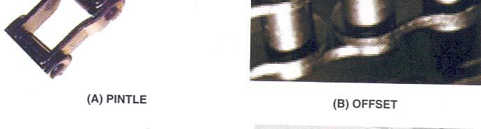
2 2 Power transmission chains have two things in common; side bars or link plates, and pin and bushing joints. The chain articulates at each joint to operate around a toothed sprocket. The pitch of the chain is the distance between the center of the articulating joints Power-transmission chains have several advantages: relatively unrestricted shaft center distances, compactness, ease of assembly, elasticity in tension with no slip or creep, and ability to operate in a relatively high-temperature atmosphere. Basic Types -There are six major types of power- transmission chains, with many modifications and special shapes for specific applications. A seventh type, the bead chain, is often used for light-duty applications. Pitch

3 3 Chain types
 and heavier loads.")
4 4 Basic Types Detachable Pitch range from in 23 to 103 mm and ultimate strength of 700 to 17,000 psi. Made in steel, does not require lubrication. Used in farm machinery. The ends of the detachable link are referred to as bar end & hook end Pintle Speeds to about 450 ft/min (2.2m/s) and heavier loads. Made up of individual cast links having a full, round barrel end with offset sidebars: inter-coupled with steel pins. Ends of pintle chain links referred as the barrel end and open end. Pitch range from (25 to 150mm) and strength of 3600 to 30,000 psi (25 200MPa)
 and transmit loads to about 250 hp (185")

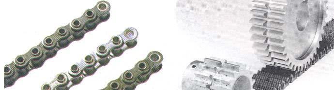
5 5 Basic Types Offset-Sidebar Used widely as drive chain on construction machinery. Operate at speeds to 1000 ft/min (5 m/s) and transmit loads to about 250 hp (185 kw). Each link has two offset sidebars, one bushing, one roller, one pin, and if the chain is detachable, a cotter pin. Some offset-sidebar chains are made without rollers


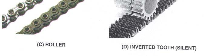
6 6 Roller: Basic Types Pitch range from in (6 to 75mm) pitch and strength of 925 to 130,000psi (6-900MPa) in single width. Available in multiple widths Small pitch sprocket Can operate at 10,000rpm at 1000 to 1200hp. Assembled with roller links and pin links, if detachable, cotter pins are used Self lubrication is possible


7 7 Basic Types Double-Pitch Same as roller chains except that t the pitch is twice as long. Have the same diameter pins and rollers, the same width rollers, and the same thickness of link plates. Inverted-Tooth (Silent) High-speed chains, used predominantly for prime-mover, power takeoff drives, such as on power cranes or shovels, machine tools, and pumps. Drives transmitting up to 1200 hp (900 kw) areinuse


8 8 Sprockets Basic sprocket types used with precision steel roller chains conform to ANSI standards Used for mounting flanges, hubs or other devices, the plate sprocket is a flat, hubless sprocket Small and medium sized hub sprockets are turned from bar stock or forgings or, are made from welding a bar-stock hub to a hot rolled plate For small, light load applications, one hub extension is needed and large sprockets have two hub projections equidistant from the center plane They are made from gray iron castings or cast steel Sprockets made of sintered metal and plastics are economical Plastics offer advantage as they require minimum lubrication and are used when cleanliness is essential
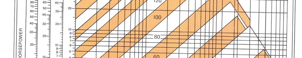
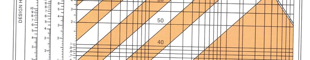
9 9 Design of Roller Chain Drives The design of a roller chain drive consists: Selection of the chain and sprocket sizes; determination of chain length, center distance, method of lubrication; and arrangement of chain casings and idlers. Belt drives based on linear speeds in fpm or m/s. Chain drives based on rotating speed (rpm) of the smaller sprocket (driver member in most installations). Design of chain drives based on the following factors: Average hp (kilowatts) to be transmitted (Fig ), RPM of the driving and driven members, Shaft diameter. Permissible diameters of sprockets.
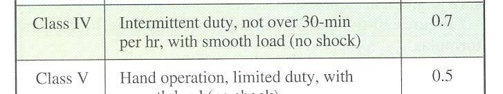
10 10 Design of Roller Chain Drives Load characteristics, whether smooth and steady, pulsating, heavy-starting, ti or subject to peaks. Fig Lubrication, whether periodic, occasional, or copious. When chains are exposed to dust, dirt, or injurious foreign matter, chain cases should be used Life expectancy: the amount of service required or the Life expectancy: the amount of service required, or the total life. It is much better to "over-chain" than to skimp on the size of the chain used.

")

11 11 Design of Roller Chain Drives The rpm and size of the smaller or faster moving sprocket determines the chain size. Smaller pitch chains in single or multiple l widths are adaptable for increased speed drives and for any speed drives where smooth (quiet) performance is needed Large pitch chains are adaptable for slow and medium speed drives Multiple-width roller chains popular, operate at different speeds with high loads and smooth in action (low noise).
12 12 Design of Roller Chain Drives Size of Sprockets - Use a minimum size sprocket of 17 teeth to obtain smooth operation at high speeds. 19 or 21-tooth sprockets used for greater life expectancy and smoother operation (lesser tooth impact slower speed). On slow-speed and special-purpose installations or where space limitations are involved, sprockets smaller than 17-tooth can be used. The normal maximum number of teeth is 120. Ordinary practice indicates: Ratio of driver to driven sprockets should be no more than 6 to 1. Recommended chain wrap on the driver is 120.
13 13 Design of Roller Chain Drives Chain Tension Chains should never run with both sides tight. Provide adjustable centers to permit proper initial slack and to allow for periodic adjustment due to natural chain wear. The chain sag should be equivalent to approximately 2% of the center distance (Fig ). Idler sprockets used as a means of taking up chain slack when it is not possible to provide adjustable centers.
14 14 Design of Roller Chain Drives Center Distances Best results are obtained by using a center distance of 30 to 50 times the pitch of the chain used. 80 times the pitch is considered maximum. Chain Length Function of the number of teeth in both sprockets and of the center distance. Chain must consist of an integral number of pitches, with an even number preferable to avoid the use of an offset link.
15 15 Design of Roller Chain Drives
16 16 Design of Roller Chain Drives Chain Length Formula - Compute the chain length in terms of chain pitches and then to multiply pythe result by the chain pitch to obtain the length in inches (millimeters). (Fig ). 1. Divide the center distance in inches (millimeters) by the pitch of the chain, obtaining C. 2. Add the number of teeth in the small sprocket to the number of teeth in the large sprocket, obtaining M. 3. Subtract the number of teeth in the small sprocket from the number of teeth in the large sprocket, obtaining value F to obtain the corresponding value of S. M S 4. Chain length in pitches equals: 2 C C Round-off the length to the next higher integer, preferable even number. The center distance must then be corrected. 5. Multiply the number of pitches by the chain pitch used in order to get the chain length in inches (millimeters).
17 17 Design of Roller Chain Drives


18 18 Design of Roller Chain Drives Drive Selection The horsepower (kilowatt) ratings relate to the speed of the smaller sprocket,, and drive selections are made on this basis (speed- reducing or speed-increasing). Dependent on loads imposed on the chain by the type of input power and the type of equipment to be driven. Service factors are used to compensate for these loads.
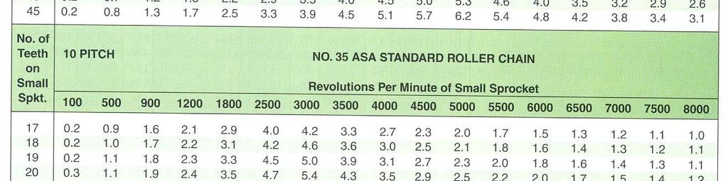
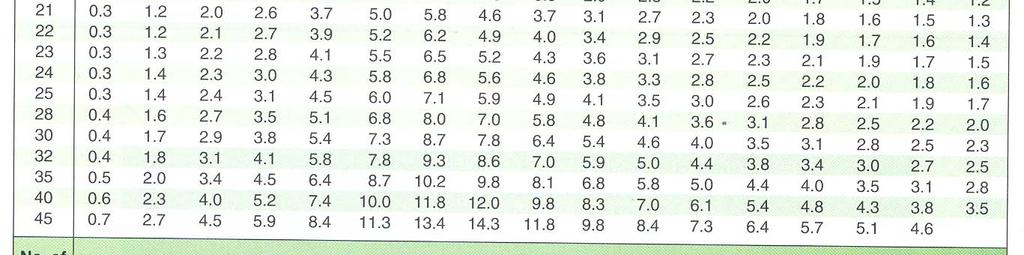
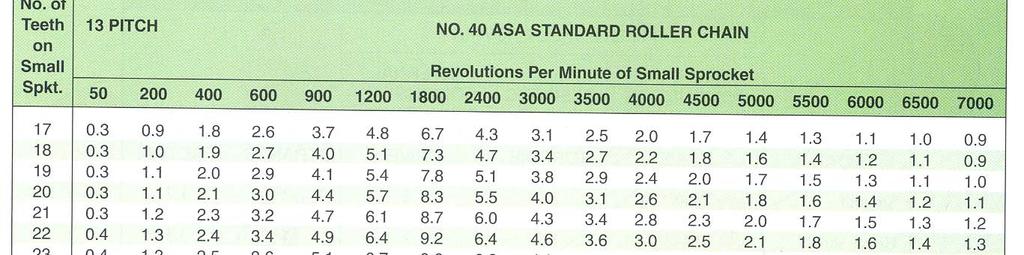
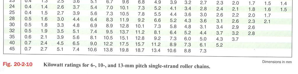
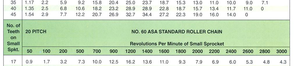
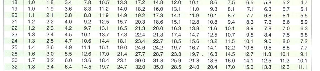
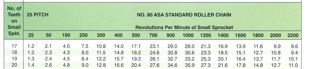
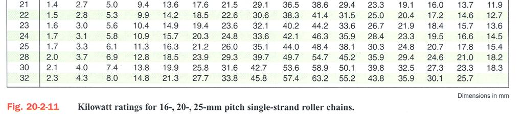
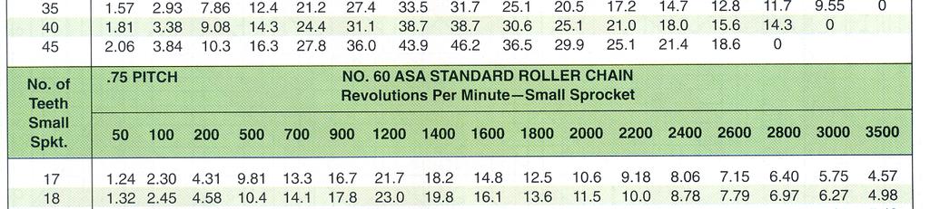
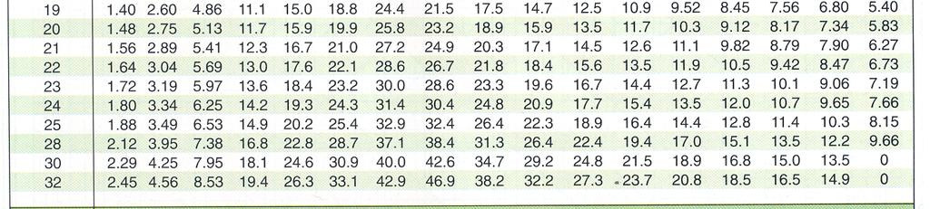
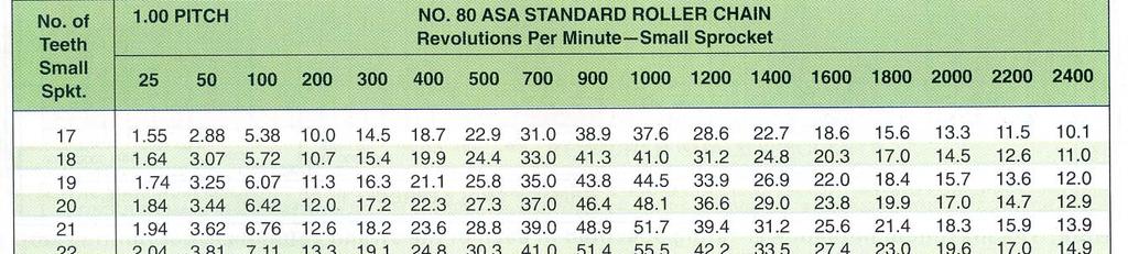
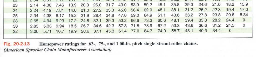
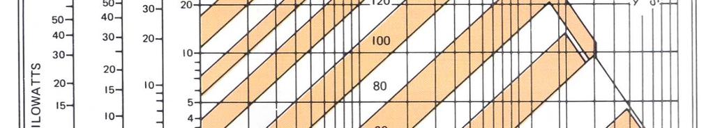
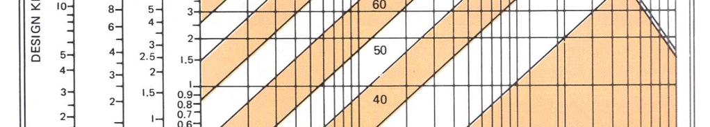
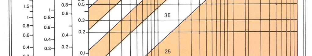
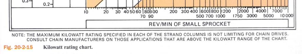
19 19 Design of Roller Chain Drives Required horsepower (kw) rating of the chain(fig ): Required hp (kw) rating = hp (kw) to be transmitted X service factor Multiple strand factor Figures to (pp ) show the hp and kw ratings for few of the many roller chains available. For more info, refer to catalogs. The hp and kw rating charts (Figs and ) provide a quick means of finding the probable chain requirements (See pp. 758 and 759.)
20 20 Chain Drive Design Example 1 Select aroller chain di driven by anelectric motor to transmit 5 hp from a countershaft to the main shaft of a wiredrawing machine. The countershaft is 1.5 in. in diameter and operates at 1200 rpm. The main shaft is also 1.5 in. and must operate between 378 and 382 rpm. Shaft centers, once established, are fixed, and by initial calculations must be approximately 22.5 in. The load on the main shaft is uneven and presents peaks that places it in the heavy-shock load category. Solution Step 1: Service Factor - The corresponding service factor from Fig for heavy-shock load and electric motor is 1.5
21 21 Chain Drive Design Solution: Step 1: Service Factor Corresponding service factor from Fig for heavy-shock load and electric motor = 1.5 Step 2: Design Horsepower Design horsepower = 5 X 1.5 = 7.5 hp
22 22 Chain Drive Design
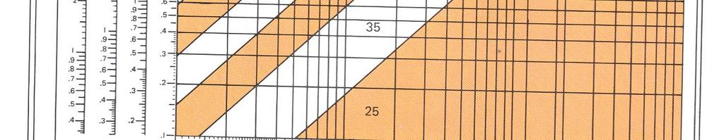
23 23 Chain Drive Design Step 3: Tentative Chain Selection Given the sprocket speed (driver) = 1200rpm, and design horse power = 7.5hp., using the horsepower rating chart (Fig ) yields the chain number to be 40. Given chain number = 40, the chain pitch =.50in from Fig Multiple-strand chain selected but using single strand data, required horsepower rating per strand is: Required horsepower rating = Multiple strand factor from Fig Design hp multiple-strand factor Or refer to the right-handhand columns shown in Fig or 15.

24 24 Chain Drive Design
25 25 Chain Drive Design Step 4: Final Selection of Chain and Small Sprocket Given chain No. = 40, small sprocket speed =1200 rpm, the computed design = 7.5 hp. Using Fig Go down the column headed by the small sprocket speed of 1200 rpm and find the nearest value to the design horsepower 7.69hp. Follow this line horizontally to the left to find the number of teeth for the small sprocket = 20. For intermediate speeds or sprocket sizes not tabulated, interpolate between the appropriate columns or lines.


26 26 Chain Drive Design
27 27 Chain Drive Design Check the maximum bore for the selected sprocket : Given chain pitch =.50in, number of small sprocket teeth = 20. Using Fig Go down the.50in chain pitch column and go along the 20 teeth row, the intersection = maximum small sprocket bore diameter = 1.78in. Greater that the given 1.50in shaft diameter (Countershaft) Hence sprocket can accommodate the 1.50in shaft. If the selected sprocket will not accommodate the shaft, use a larger sprocket or make a new sprocket and chain selection from the rating table for the next-larger chain number.


28 28 Chain Drive Design.
29 29 Chain Drive Design Step 5: Selection of the Large Sprocket Driver speed = 1200 rpm ; Driven speed at a min of 378 rpm; Speed ratio = 1200/378 = 3.17:1 1 min. Large sprocket = 20 X 3.17 = 63.4 teeth Standard sprocket sizes near this number of teeth are either 60 or 70 teeth (Fig ). More economical and time-saving to try to use a combination of standard sprockets.


30 30 Chain Drive Design Rechecking smaller sprocket, 19-tooth sprocket also OK. (Drop safety margin) Large sprocket of 19 X 3.17 teeth = 60.2 teeth (use 60 teeth). 19- and 60-tooth sprockets are acceptable and standard. More economical to use this combination.
31 31 Chain Drive Design Step 6: Chain Length in Pitches 19- and 60-tooth sprockets are to be placed on 22.5-in. centers. Chain length in pitches = M S 2C + + where 2 C C = center distance pitch = = 45 M = total number of teeth on both sprockets = = 79 F = = 41 S = (value obtained from table ) Substituting values for C, M, and S, we get Chain length in pitches = = The chain is to couple to an even number of pitches, use 130 pitches because the leeway on the 22.5 in. centers is not critical
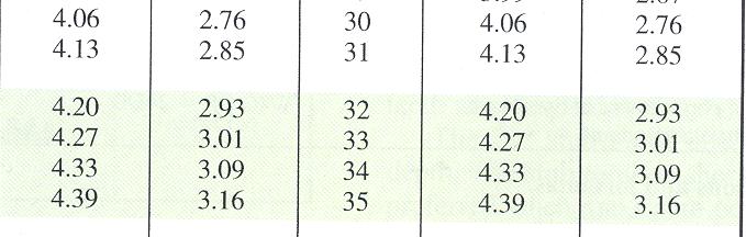
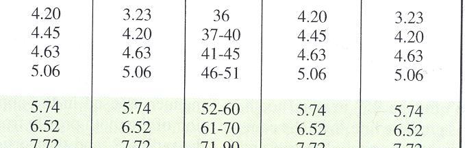
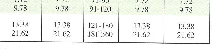
32 32 Chain Drive Design Step 7: Chain Length in Inches (Millimeters) Length of chain = number of pitches X pitch = 130 X.5 = 65 in. For metric chain problems the same procedures are followed except that t Figs , , and replace Figs , , 2 and
33 33 Chain Drive Design

34 34 Metric units Table


35 35 Chain Drives Metric units Table


36 36 Chain Drives Metric units Table

37 37 Metric units Figure
38 38


 Most")


39 39 Gear Drives Gear Drives transmit motion (rotary or reciprocating) from one part to another Reduce or increase revolutions of shaft Gears cylinders or cones having teeth (for positive motion) Most durable (used in automotive and heavy duty Based on shaft position, gears are classified as Spur, Bevel, Worm and Rack & Pinion

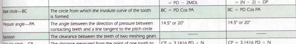
40 40 Gear Drives Spur Gears Spur gear proportions and the shape of gear teeth are standardized, and the definitions, symbols, and formulas are given in Figs to Gears used to transmit motion at constant angular velocity The form of the gear that produces this constant velocity is involute
 Every involute gear has one base circle from which all involutes")
 is the")

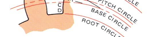
41 41 Gear Drives Spur Gears Involute curve traced by a point on a string unwinding from a circle (base circle) Every involute gear has one base circle from which all involutes are generated (not a physical part of the gear) Line of Action tangent to and crosses the base circles at contact Pressure angle - (also referred to as tooth shape ) is the angle at which the pressure from the tooth of one gear is passed on to the tooth of another gear. Spur gears come in two PA s: 14.5º and 20º
42 42
43 43 Gear Drives Drawing Gear Teeth Exact form is time consuming, approximate methods are used and the two most common methods are shown in the figure below First layout root, pitch and outside circles. Mark circular thickness on the pitch circle. With the line tangent to pitch circle draw pressure line (14.5 or 20 )
44 44 Gear Drives Drawing Gear Teeth Draw the base circle tangent to this pressure line With radius = 1/8 th the pitch dia and center on base circle draw arcs through the circular thickness, from base circle to top of the teeth Below the base circle, the teeth is drawn with a radial line ending in a fillet to the root diameter


45 45 Gear Drives Drawing Gear Teeth More closer approximation use grants representation R and r for inch gears value divided by the diametral pitch; for metric, the value times the module
46 46 Gear Drives Working Drawing of Spur Gears Sectional view is enough. If web or arm details are needed, the front view is drawn Teeth need not be shown in the front view, phantom lines for outside and root circles and center line for pitch circle to be used (ANSI) In section view, root and outside circle are shown as solid lines Gear blank is dimensioned in the drawing and teeth information in table as they are made by 2 different processes
47 47 Gear Drives Working Drawing of Spur Gears
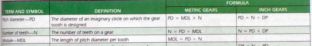
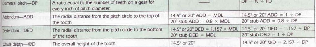
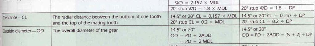
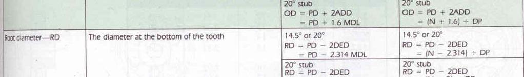
48 48 Gear Drives Working Drawing of Spur Gears The only differences in terminology between inch and metric-size gear drawings are the terms diametrical pitch (DP) and module (MDL) For inch gears, DP is used. DP is a ratio of the number of teeth to a unit length of pitch diameter. DP = N/PD For metric gears, MDL is used. It is the length of pitch diameter per tooth measured in millimeters. MDL = PD/N From these definitions it can be seen that the MDL is equal to the reciprocal of the DP and not its metric dimensional equivalent. If the DP is known, the MDL can be obtained. MDL = 25.4 DP Gears here are designed in the inch and have a standard DP instead of a preferred standard MDL. Therefore, DP is referenced beneath the MDL when gears designed with standard inch pitches are used
49 49 Gear Drives Working Drawing of Spur Gears For gears designed with standard MDL, the DP need not be referenced on the gear drawing. The standard modules for metric gears are 0.8, I, 1.25, 1.5, 2.25, 3, 4, 6, 7, 8, 9, 10, 12, and 16 For metric gear calculations, the DP is soft-converted to MDL in Fig for comparison purposes and for use in assignments Spur Gear Calculation Center Distance - The distance between the two shaft centers is sum of pitch diameter of the two gears divided by 2 Example 1 - A 12-DP, 36-tooth pinion mates with a 90-tooth gear Find the center distance
50 50 Gear Drives Spur Gear Calculation Pitch diameter (PD) = number of teeth (N) DP For gear 1 (PD) = = 3.00 in. (pinion- smaller gear) For gear 2 (PD) = = 7.50 in. (gear) Sum of the two PDs = 3.00 in in. = in. Center distance = 10.50/2 = 5.2 Ratio of the gear is the relationship between any of the following: RPM of the Gears Number of teeth on the gears Pitch diameter of the gears The ratio is obtained by dividing idi the larger value of these 3 parameters by the corresponding smaller value
51 51 Gear Drives Spur Gear Calculation Determining Pitch and Outside diameter Pitch diameter (PD) can be found if number of teeth (N) and diametral pitch (DP) or module (MDL) is known The outside diameter (OD) is equal to the pitch diameter plus 2 addendums The addendum for a gear tooth is 1/DP or the MDL
52 52 Power Transmission Capacity Spur Gears Gear drives are required to operate under such a wide variety of conditions that it is very difficult and expensive to determine the best gear set for a particular application. The most economical procedure is to select standard stock gears with an adequate load rating for the application Approximate hp (kw) ratings for spur gears of various sizes (numbers of teeth), at several operating speeds (rpm) are given in catalogs with the spur gear listings. Ratings for gear sizes and/ or speeds not listed may be estimated from the values shown on page 768 in Fig
53 53 Power Transmission Capacity Spur Gears Pitch-line velocities exceeding 1000 ft/min (5 m/s) for 14.5 PA (pressure angle), or 1200 ft/min (6 m/s) for 20 PA, are not recommended for metallic spur gears. Ratings are listed for speeds below these limits The ratings given (or calculated) should be satisfactory for gears used under normal operating conditions, i.e., when they are properly mounted and lubricated, carrying a smooth load (without shock) for 8 to 10 hours a day The charts shown in Fig indicate the approximate hp (kw) ratings of 16- and 20-tooth steel spur gears of several tooth sizes operating at various speeds
54 54 Power Transmission Capacity Spur Gears They may be used to determine the approximate DP or MDL of a 16- or 20-tooth steel pinion that will carry the hp (kw) required at the desired speed. The intersection of the lines representing values of rpm and hp (kw) indicates the approximate gear DP (MDL) required The number of teeth th normally should not be less than 16 to 20 in a pinion, or less than 13 in a 20 pinion Ratings shown for spur gears in catalogs normally are for class 1 service. For other classes of service, the service factors in Fig (p. 769) should be used


55 55 Power Transmission Capacity Selecting the Spur Gear Drive
56 56 Power Transmission Capacity Selecting the Spur Gear Drive 1. Determine the class of service 2. Multiply the horsepower (kilowatts) required for the application by the service factor 3. Select spur gear pinion with catalog rating hp (kw) determined in step 2 4. Select driven spur gear with a catalog rating hp (kw) determined in step 2
57 57 Power Transmission Capacity Selecting the Spur Gear Drive Example 1 - Select a pair of 20 spur gears that will drive a machine at 150rpm. Size of driving motor = 25hp, 600rpm. Service factor = 1 Solution - Since service factor = 1, we need not increase or decrease the design hp. Refer charts in Fig A, which h show design data for 20 spur gears having 16 and 20 teeth. Selecting a pinion having 16 teeth and reading vertically on the column showing 600 rpm to hp rating of 25, we find that required DP = 4. (Select the DP equal to or greater than hp) Pinion: N = 16, DP = 4, PD = 16 4 = in. Ratio = 600/150 = 4:1 Gear: N = 16 X 4 = 64, DP = 4, PD = 64 4 = in required
58 58 Power Transmission Capacity Selecting the Spur Gear Drive
59 59 Power Transmission Capacity Selecting the Spur Gear Drive
60 60 Power Transmission Capacity Selecting the Spur Gear Drive
61 61 Power Transmission Capacity Example 3 A 7.5-kW; 900-r/min motor is attached by means of 14.5 spur gears to a punch that operates 24 hours a day. Gear ratio: 4 to 1. Assuming the punch is being operated at motor capacity. Solution: Machine operating conditions = Service class 3 = Service factor of 1.3. Therefore: Kilowatts required for design purposes = = 9.75 kw. Pinion mounted on motor and runs at 900 r/min. Refer to Fig B. Select either a pinion having a module of 5.08 and N of 20 or a module of 6.35 and N of 16. First, module of 5.08mm: Pinion: N = 20, MDL = 5.08, PD = mm. Gear travels at 225 r/min, or one-fourth of pinion revolutions per minute. Gear: N = 4 20=80 80, MDL= , PD= = mm
62 62 Power Transmission Capacity Selecting the Spur Gear Drive Example 3 Second, using a module of 6.35mm: Pinion: N = 16, MDL = 6.35, PD = mm. Gear: N = 64, MDL = 6.35, PD = mm. Both sets of gears are of the same diameter, the overall size is not a factor. Extra strength of gear set with module of 6.35 not required. Considerable savings by selecting the gear and pinion having the module of Hence gear and pinion with module of 5.08 selected.
Gear Engineering Data. Spur Gear Gear Formulas Drive Selection Horsepower and Torque Tables
 Engineering Gear Engineering Data Spur Gear Gear Formulas Drive Selection Horsepower and Torque Tables G-79 Gear Selection Stock Spur Gear Drive Selection When designing a stock gear drive using the horsepower
Sheet 1 Variable loading
 Sheet 1 Variable loading 1. Estimate S e for the following materials: a. AISI 1020 CD steel. b. AISI 1080 HR steel. c. 2024 T3 aluminum. d. AISI 4340 steel heat-treated to a tensile strength of 1700 MPa.
Gear Tooth Geometry - This is determined primarily by pitch, depth and pressure angle
 Gear Tooth Geometry - This is determined primarily by pitch, depth and pressure angle Addendum: The radial distance between the top land and the pitch circle. Addendum Circle: The circle defining the outer
Graphical representation of a gear
 Homework 4 Gears Gears are designed to transmit rotary motion. Often they are arranged in a gear train (meshed together). Gear trains provide a change in speed, torque (turning force) and direction (clockwise
GEAR CONTENTS POWER TRANSMISSION GEAR TYPES OF GEARS NOMENCLATURE APPLICATIONS OF GEARS VELOCITY RATIO GEAR TRAINS EXAMPLE PROBLEMS AND QUESTIONS
 GEAR CONTENTS POWER TRANSMISSION GEAR TYPES OF GEARS NOMENCLATURE APPLICATIONS OF GEARS VELOCITY RATIO GEAR TRAINS EXAMPLE PROBLEMS AND QUESTIONS GEAR.. Power transmission is the movement of energy from
1/2/2015 2:04 PM. Chapter 13. Gears General. Dr. Mohammad Suliman Abuhaiba, PE
 Chapter 13 Gears General 1 2 Chapter Outline 1. Types of Gears 2. Nomenclature 3. Conjugate Action 4. Involute Properties 5. Fundamentals 6. Contact Ratio 7. Interference 8. The Forming of Gear Teeth 9.
12/6/2013 9:09 PM. Chapter 13. Gears General. Dr. Mohammad Suliman Abuhaiba, PE
 Chapter 13 Gears General 1 2 Chapter Outline 1. Types of Gears 2. Nomenclature 3. Conjugate Action 4. Involute Properties 5. Fundamentals 6. Contact Ratio 7. Interference 8. The Forming of Gear Teeth 9.
UNIT -I. Ans: They are specified by the no. of strands & the no. of wires in each strand.
 VETRI VINAYAHA COLLEGE OF ENGINEERING AND TECHNOLOGY, THOTTIAM, NAMAKKAL-621215. DEPARTMENT OF MECHANICAL ENGINEERING SIXTH SEMESTER / III YEAR ME6601 DESIGN OF TRANSMISSION SYSTEM (Regulation-2013) UNIT
ME6601 DESIGN OF TRANSMISSION SYSTEMS
 SYED AMMAL ENGINEERING COLLEGE (Approved by the AICTE, New Delhi, Govt. of Tamilnadu and Affiliated to Anna University, Chennai) Established in 1998 - An ISO 9001:2008 Certified Institution Dr. E.M.Abdullah
Engineering Information
 Engineering nformation Gear Nomenclature ADDENDUM (a) is the height by which a tooth projects beyond the pitch circle or pitch line. BASE DAMETER (D b ) is the diameter of the base cylinder from which
(POWER TRANSMISSION Methods)
") UNIT-5 (POWER TRANSMISSION Methods) It is a method by which you can transfer cyclic motion from one place to another or one pulley to another pulley. The ways by which we can transfer cyclic motion are:-
UNIT-5 (POWER TRANSMISSION Methods) It is a method by which you can transfer cyclic motion from one place to another or one pulley to another pulley. The ways by which we can transfer cyclic motion are:-
PowerGrip GT 2 Belt Drives Twin Power
 PowerGrip GT 2 Belt Drives Twin Power Twin Power Belt Drive Systems Belt Construction Gates Twin Power Belts have teeth on both sides to provide synchronization from both driving surfaces. This special
LESSON Transmission of Power Introduction
 LESSON 3 3.0 Transmission of Power 3.0.1 Introduction Earlier in our previous course units in Agricultural and Biosystems Engineering, we introduced ourselves to the concept of support and process systems
Catalog Q Conversion For those wishing to ease themselves into working with metric gears
 1.3.4 Conversion For those wishing to ease themselves into working with metric gears by looking at them in terms of familiar inch gearing relationships and mathematics, Table 1-5 is offered as a means
 DEPARTMENT OF MECHANICAL ENGINEERING Subject code: ME6601 Subject Name: DESIGN OF TRANSMISSION SYSTEMS UNIT-I DESIGN OF TRANSMISSION SYSTEMS FOR FLEXIBLE ELEMENTS 1. What is the effect of centre distance
Chapter 8 Kinematics of Gears
 Chapter 8 Kinematics of Gears Gears! Gears are most often used in transmissions to convert an electric motor s high speed and low torque to a shaft s requirements for low speed high torque: Speed is easy
Bevel Gears. Fig.(1) Bevel gears
 Bevel gears") Bevel Gears Bevel gears are cut on conical blanks to be used to transmit motion between intersecting shafts. The simplest bevel gear type is the straighttooth bevel gear or straight bevel gear as can be
Bevel Gears Bevel gears are cut on conical blanks to be used to transmit motion between intersecting shafts. The simplest bevel gear type is the straighttooth bevel gear or straight bevel gear as can be
KINGS COLLEGE OF ENGINEERING DEPARTMENT OF MECHANICAL ENGINEERING
 KINGS COLLEGE OF ENGINEERING DEPARTMENT OF MECHANICAL ENGINEERING QUESTION BANK Sub Code/Name: ME 1352 DESIGN OF TRANSMISSION SYSTEMS Year/Sem: III / VI UNIT-I (Design of transmission systems for flexible
Marine Engineering Exam Resource Review of Couplings
 1. What are rigid couplings used for? Used to join drive shafts together. True alignment and rigidity are required. Example Drive shafts and production lines, bridge cranes, solid shaft that needs to be
Marswell Engineering Ltd.
 Marswell Engineering Ltd. Specialized in small module plastic gearing and gearbox Automated injection molding and molds for any small, precision component. Table of content page table of content i Background
CH#13 Gears-General. Drive and Driven Gears 3/13/2018
 CH#13 Gears-General A toothed wheel that engages another toothed mechanism in order to change the speed or direction of transmitted motion The gear set transmits rotary motion and force. Gears are used
Lecture (7) on. Gear Measurement. By Dr. Emad M. Saad. Industrial Engineering Dept. Faculty of Engineering. Fayoum University.
 on. Gear Measurement. By Dr. Emad M. Saad. Industrial Engineering Dept. Faculty of Engineering. Fayoum University.") 1 Lecture (7) on Gear Measurement Fayoum University By Dr. Emad M. Saad Industrial Engineering Dept. Faculty of Engineering Fayoum University Faculty of Engineering Industrial Engineering Dept. 2015-2016
1 Lecture (7) on Gear Measurement Fayoum University By Dr. Emad M. Saad Industrial Engineering Dept. Faculty of Engineering Fayoum University Faculty of Engineering Industrial Engineering Dept. 2015-2016
Introduction. Kinematics and Dynamics of Machines. Involute profile. 7. Gears
 Introduction The kinematic function of gears is to transfer rotational motion from one shaft to another Kinematics and Dynamics of Machines 7. Gears Since these shafts may be parallel, perpendicular, or
Variable Speed Drives
 -1 Why Vary Speed? Variable speed drives are needed because many applications are not run at the same speed all of the time, due to the surrounding conditions. Revolutions per minute (RPM) of the driven
SECTION 4 SPUR GEAR CALCULATIONS
 Function of α, or invα, is known as involute function. Involute function is very important in gear design. Involute function values can be obtained from appropriate tables. With the 3.1 Contact Ratio center
11. GEAR TRANSMISSIONS
 11. GEAR TRANSMISSIONS 11.1. GENERAL CONSIDERATIONS Gears are one of the most important elements used in machinery. There are few mechanical devices that do not have the need to transmit power and motion
SPROCKET ENGINEERING DATA
 Engineering SPROCKET ENGINEERING DATA ROLLER CHAIN DIMENSIONS SPROCKET TOOTH DIMENSIONS MAXIMUM HUB RECOMMENDATIONS APPLICATION AND SELECTION HARDENING CHAIN LENGTH CALCULATION SPEED RATIOS SPROCKET DIAMETERS
ME6401 KINEMATICS OF MACHINERY UNIT- I (Basics of Mechanism)
") ME6401 KINEMATICS OF MACHINERY UNIT- I (Basics of Mechanism) 1) Define resistant body. 2) Define Link or Element 3) Differentiate Machine and Structure 4) Define Kinematic Pair. 5) Define Kinematic Chain.
ME6401 KINEMATICS OF MACHINERY UNIT- I (Basics of Mechanism) 1) Define resistant body. 2) Define Link or Element 3) Differentiate Machine and Structure 4) Define Kinematic Pair. 5) Define Kinematic Chain.
Technology of Machine Tools
 PowerPoint to accompany Technology of Machine Tools 6 th Edition Krar Gill Smid Gear Cutting Unit 70 Copyright The McGraw-Hill Companies, Inc. Permission required for reproduction or display. 70-2 Objectives
CONTENTS Sprockets for Roller Chain
 CONTENTS Sprockets for Roller Chain Features/enefits.................................................... PT14-2 Specification: TAPER-LOCK, A, #35 Pitch......................................................
Chapter 3. Transmission Components
 Chapter 3. Transmission Components The difference between machine design and structure design An important design problem in a mechanical system is how to transmit and convert power to achieve required
TECHNOLOGY MECHANISMS
 TECHNOLOGY MECHANISMS 3º ESO IES CHAN DO MONTE URTAZA 1 WHAT IS A MECHANISM? Mechanism are devices that have been designed to make jobs easier. They all have certain things in common: They involve some
Instantaneous Centre Method
 Instantaneous Centre Method The combined motion of rotation and translation of the link AB may be assumed to be a motion of pure rotation about some centre I, known as the instantaneous centre of rotation.
LAMBDA Chain. U.S. Tsubaki, Inc. The Next Generation of Lube-Free Roller Chain. Better than ever!
 U.S. Tsubaki, Inc. Roller Chain Division LAMBDA Chain The Next Generation of Lube-Free Roller Chain Better than ever! Maintenance-Free Even Longer Wear Life Increased Operating Temperatures Unique Patented
SPROCKET ENGINEERING DATA
 Engineering SPROCKET ENGINEERING DATA ROLLER CHAIN DIMENSIONS SPROCKET TOOTH DIMENSIONS MAXIMUM HUB RECOMMENDATIONS APPLICATION AND SELECTION HARDENING CHAIN LENGTH CALCULATION SPEED RATIOS SPROCKET DIAMETERS
Selection Procedure, Example... PT13-16 Basic Horsepower Ratings... PT13-20
 CONTENTS Sprockets for Roller Chain V-Drives Features/Benefits.......................................... PT13-2 Specification: TAPER-LOCK, A, B #35 Pitch...............................................
Driver Driven. InputSpeed. Gears
 Gears Gears are toothed wheels designed to transmit rotary motion and power from one part of a mechanism to another. They are fitted to shafts with special devices called keys (or splines) that ensure
Moments. It doesn t fall because of the presence of a counter balance weight on the right-hand side. The boom is therefore balanced.
 Moments The crane in the image below looks unstable, as though it should topple over. There appears to be too much of the boom on the left-hand side of the tower. It doesn t fall because of the presence
Fig. 1 Two stage helical gearbox
 Lecture 17 DESIGN OF GEARBOX Contents 1. Commercial gearboxes 2. Gearbox design. COMMERICAL GEARBOX DESIGN Fig. 1 Two stage helical gearbox Fig. 2. A single stage bevel gearbox Fig. 4 Worm gearbox HELICAL
CHAPTER 6 GEARS CHAPTER LEARNING OBJECTIVES
 CHAPTER 6 GEARS CHAPTER LEARNING OBJECTIVES Upon completion of this chapter, you should be able to do the following: Compare the types of gears and their advantages. Did you ever take a clock apart to
Specifications. Trantorque GT CALL FAX
 GT Specifications The following pages contain engineering data and product specifications for GT. For CAD drawings of GT, please click on the part number to download the drawing. All drawings are in AutoCAD
Power Jacks have taken time, engineering excellence and the best people to produce the ultra compact Neeter Drive gearbox.
 202 www.powerjacks.com Power Jacks have taken time, engineering excellence and the best people to produce the ultra compact Neeter Drive gearbox. Our expertise has been built on a history of engineering
1.6 Features of common gears
 1.6 Features of common gears Chapter 1.2 covered briefly on types of gear. The main gear features are explained here. Helical gear Helical gear has characteristics of transferability of larger load, less
SKF Disc Couplings. Selection
 SK Disc Couplings The SK disc coupling is the ideal solution in medium to high applications that require torsional rigidity, offer some allowance for misalignment, and do not require lubrication. These
Metrology Prof. Dr Kanakuppi Sadashivappa Bapuji Institute of Engineering and Technology Davangere. Lecture 25 Introduction of Gears
 Metrology Prof. Dr Kanakuppi Sadashivappa Bapuji Institute of Engineering and Technology Davangere Lecture 25 Introduction of Gears I welcome you for the series of lecture on gear measurement and at module
Installation Tensioning Procedure
 Contents PARTICULARS Introduction PIX X treme HTD Belts Construction Features Designation Pitch range Length range Pulley Dimensions Length tolerances Width tolerances PIX X treme Classical Belts Construction
Ribbed Belts FRICTION BELT DRIVES FRICTION BELT DRIVES. Drive Design & Maintenance Manual
 BELT DIMENSIONS & PHYSICAL PROPERTIES Belt Section PJ PK PL PM Rib pitch E (mm) 2.4.56 4.70 9.40 Belt thickness H (mm).50 5.00 7.00 12.00 Mass/unit length/rib (g/m/rib) 8.20 19.50 2.00 110.00 Maximum belt*
Basic Fundamentals of Gear Drives
 Basic Fundamentals of Gear Drives Course No: M06-031 Credit: 6 PDH A. Bhatia Continuing Education and Development, Inc. 9 Greyridge Farm Court Stony Point, NY 10980 P: (877) 322-5800 F: (877) 322-4774
Cross Tensioners. Frames. Bearings. Springs. Mounting Holes. Adjustment Marks
 Cross Tensioners Cross Tensioners provide constant belt or chain tension. Their automatic tensioning action translates into improved performance and extended life for most types of fixed-centre drives.
4 Fenner Torque Drive Plus 3
 Fenner Torque Drive Plus 3 offers; State of the art power ratings. Compact drive package - reduced weight. Quiet operation. Accuracy of positioning. Anti-static as standard. Runs on standard HTD pulleys.
CONTENT. 1. Syllabus 2. Introduction 3. Shaft 4. Coupling. Rigid coupling. Flange coupling. Sleeve (or) muff coupling Split muff coupling
 muff coupling Split muff coupling") UNIT II 1. Syllabus 2. Introduction 3. Shaft 4. Coupling Rigid coupling CONTENT Flange coupling Protected flange coupling Unprotected flange coupling Marine type flange coupling Sleeve (or) muff coupling
UNIT II 1. Syllabus 2. Introduction 3. Shaft 4. Coupling Rigid coupling CONTENT Flange coupling Protected flange coupling Unprotected flange coupling Marine type flange coupling Sleeve (or) muff coupling
Chapter 11. Keys, Couplings and Seals. Keys. Parallel Keys
 Chapter 11 Keys, Couplings and Seals Material taken for Keys A key is a machinery component that provides a torque transmitting link between two power-transmitting elements. The most common types of keys
SCREW JACK POWER TRANSMISSION COMPONENTS TYPICAL SYSTEM ARRANGEMENTS
 TYPICAL SYSTEM ARRANGEMENTS Duff-Norton offers all of the components necessary to complete your power transmission system, whether it consists of a single actuator or a multiple actuator arrangement. We
Tooth thickness Dedendum. Addendum. Centre distance Nominal
 FORMULAS SPUR GEARS TO FIND:- PCD ØD MODULE No. of TEETH CP ADDENDUM DEDENDUM MODULE No. of TEETH x MOD (mm) (No. of TEETH + ) x MOD (mm) 5.4 MODULE CP π (mm) PCD MODULE (mm) MODULE x π (mm) MODULE (mm)
Chapter 1 Gear Design
 Chapter 1 Gear Design GTU Paper Analysis Sr. No. Questions Nov 16 May 17 Nov 17 May 18 Theory 1. Explain the following terms used in helical gears: (a) Helix angle; (b) Normal pitch; (c) Axial pitch; (d)
Part VII: Gear Systems: Analysis
 Part VII: Gear Systems: Analysis This section will review standard gear systems and will provide the basic tools to perform analysis on these systems. The areas covered in this section are: 1) Gears 101:
Features / Benefits Fixed Pitch Drives... PT8-2 Variable Pitch Drives... PT8-2
 CONTENTS V-Drives Features / Benefits Fixed Pitch Drives......................................... PT8-2 Variable Pitch Drives....................................... PT8-2 Selection/Dimensions Light Duty
U.S. TSUBAKI DRIVE CHAINS
 DRIVE CHAINS Contents Page ANSI RS ROLLER CHAIN A- ~ A-4 INTRODUCTION A- ~ A-5 RS5 THROUGH RS4 A-6 ~ A-9 HEAVY SERIES A- RS DOUBLE PITCH ROLLER CHAINS A- SELECTION AND ENGINEERING INFORMATION A- ~ A-4
MECH 1200 Quiz 2 Review
 Name: Class: Date: MECH 1200 Quiz 2 Review True/False Indicate whether the statement is true or false. 1. Gears are machined toothed wheels that engage other toothed wheels to transfer power and torque.
Program Internal Gear Set Profile Shift Coefficients With Zero Backlash Introduction
 Program 60-107 Internal Gear Set Profile Shift Coefficients With Zero Backlash Introduction The purpose of this model is to provide data for a gear set when the tooth thickness and/or the center distance
Mechanism Feasibility Design Task
 Mechanism Feasibility Design Task Dr. James Gopsill 1 Contents 1. Last Week 2. Types of Gear 3. Gear Definitions 4. Gear Forces 5. Multi-Stage Gearbox Example 6. Gearbox Design Report Section 7. This Weeks
Introduction to Gear Design
 Introduction to Gear Design Course No: M03-016 Credit: 3 PDH Robert P. Tata, P.E. Continuing Education and Development, Inc. 9 Greyridge Farm Court Stony Point, NY 10980 P: (877) 322-5800 F: (877) 322-4774
Series PVP Variable Volume Piston Pumps
 Series PVP Variable Volume Piston Pumps Catalog HY28-2661-CD/US zp2 hpm12-1.p65, lw, jk 1 Notes Series PVP hpm12-1.p65, lw, jk 2 Introduction Series PVP Series Sizes 6-14 Phased Out For Reference Only
2. a) What is pantograph? What are its uses? b) Prove that the peaucellier mechanism generates a straight-line motion. (5M+10M)
 What is pantograph? What are its uses? b) Prove that the peaucellier mechanism generates a straight-line motion. (5M+10M)") Code No: R22032 R10 SET - 1 1. a) Define the following terms? i) Link ii) Kinematic pair iii) Degrees of freedom b) What are the inversions of double slider crank chain? Describe any two with neat sketches.
Code No: R22032 R10 SET - 1 1. a) Define the following terms? i) Link ii) Kinematic pair iii) Degrees of freedom b) What are the inversions of double slider crank chain? Describe any two with neat sketches.
The gear boxes can be run at the same speeds as the actuator models. Do not exceed torque ratings.
 1. What is the lifting torque required? The lifting torque for a single actuator depends on the load, the worm gear ratio, type of screw (machine cut or ball screw) and the pitch of the lifting screw.
KINEMATICS OF MACHINARY UBMC302 QUESTION BANK UNIT-I BASICS OF MECHANISMS PART-A
 KINEMATICS OF MACHINARY UBMC302 QUESTION BANK UNIT-I BASICS OF MECHANISMS PART-A 1. Define the term Kinematic link. 2. Classify kinematic links. 3. What is Mechanism? 4. Define the terms Kinematic pair.
Chapter seven. Gears. Laith Batarseh
 Chapter seven Gears Laith Batarseh Gears are very important in power transmission between a drive rotor and driven rotor What are the functions of gears? - Transmit motion and torque (power) between shafts
Different types of gears. Spur gears. Idler gears. Worm gears. Bevel gears. Belts & Pulleys
 GEARS Robot Gears By using different gear diameters, you can exchange between rotational (or translation) velocity and torque. by looking at the motor datasheet you can determine the output velocity and
PLASTICS INDEX...L-1 PLASTIC CAPABILITIES...L-2
 Index SECTION L PRODUCT PAGE INDEX...L-1 PLASTIC CAPABILITIES...L-2 SECTION I NON-METALLIC SPROCKETS...L-3 - L-12 Sprockets - Stock No. 25 1/4" Pitch...L-3 No. 35 3/8" Pitch...L-4 No. 40 1/2" Pitch...L-5
HTD Pulley & Belt Drives
 HTD Pulley & elt Drives HTD timing belts offer optimised load distribution through the rounded tooth form, guaranteeing high power transmission in low speed and high torque applications. apable of transmitting
ROLLER CHAIN SPROCKETS INDEX...E-1 E-2 MADE-TO-ORDER CAPABILITIES...E-3
 Index SECTION E ROLLER CHAIN SPROCKETS PRODUCT PAGE INDEX...E-1 E-2 MADE-TO-ORDER CAPABILITIES...E-3 SECTION I STANDARD SPROCKETS...E-4 E-112 Shear Pin Sprockets, Bolt-On...E-4 E-6 Type D Sprockets, Detachable
DESIGN OF MACHINE MEMBERS - I
 R10 Set No: 1 III B.Tech. I Semester Regular and Supplementary Examinations, December - 2013 DESIGN OF MACHINE MEMBERS - I (Mechanical Engineering) Time: 3 Hours Max Marks: 75 Answer any FIVE Questions
General gear terms and definitions. Trantorque 48 DP. Steel and Brass
 General gear terms and definitions 317 Spur and Helical Gears: Formulae and definitions Helical Gear Spur Gear Term Definition formulae formulae 318 Spur and Helical Gears: Formulae and definitions Helical
FEATURES / BENEFITS... 2 SPECIFICATION / HOW TO ORDER... 4 NOMENCLATURE... 11
 CONTENTS QUANTIS RHB FEATURES / BENEFITS.................................... 2 SPECIFICATION / HOW TO ORDER........................... 4 NOMENCLATURE......................................... 11 GEARMOTORS
Products Catalogue. Quality Guaranteed
 Products Catalogue CHAINS The GB range of Chains, Sprockets, Couplings and Pulleys has evolved from 20 years expertise in the importation and sale of the products locally in the Australia. The GB range
Vickers. Vane Pumps. Double Thru-drive Vane Pumps. High speed, high pressure VQT Series for mobile equipment. Released 7/93
 Vickers Vane Pumps Double Thru-drive Vane Pumps High speed, high pressure VQT Series for mobile equipment Released 7/93 612 Introduction Double VQT high performance pumps are fixed displacement units that
Chapter 11 Rolling Contact Bearings
 Chapter 11 Rolling Contact Bearings 1 2 Chapter Outline Bearing Types Bearing Life Bearing Load Life at Rated Reliability Bearing Survival: Reliability versus Life Relating Load, Life, and Reliability
High Tech High Top Hat Technicians. Gearbox Design as Seen Through the Toughbox. Gear Up
 High Tech High Top Hat Technicians Gearbox Design as Seen Through the Toughbox Or Gear Up Toughbox Gear Pairs Diametral Pitch (DP): 20 per inch Pressure angle: 14.5 degrees Gear Teeth 14 50 16 48 19 45
EXPANSION JOINT SELECTION GUIDE
 EXPANSION JOINT SELECTION GUIDE The proper selection and application of an expansion joint is the determining factor in its operation and life. Improper selection and application will lead to problems
What are the functions of gears? What is gear?
 8//0 hapter seven Laith atarseh are very important in power transmission between a drive rotor and driven rotor What are the functions of gears? - Transmit motion and torque (power) between shafts - Maintain
MECHANICAL DRIVES 1 SPUR GEAR DRIVES LEARNING ACTIVITY PACKET BB502-XD06AEN
 MECHANICAL DRIVES 1 LEARNING ACTIVITY PACKET SPUR GEAR DRIVES BB502-XD06AEN LEARNING ACTIVITY PACKET 6 SPUR GEAR DRIVES INTRODUCTION This LAP will begin the study of the third type of adjacent shaft-to-shaft
GatesFacts Technical Information Library Gates Compass Power Transmission CD-ROM version 1.2 The Gates Rubber Company Denver, Colorado USA
 SIZING UP V-RIBBED BELTS Gary Porter Machine Design October 22, 1992 V-ribbed belts offer several advantages to power transmission drive design. Classical V-belts have a profile shaped like a modified
Roller chain idler sprocket units Idler pulley units
 Roller chain idler sprocket units Idler pulley units Roller chain idler sprocket units, idler pulley units Page Product overview Roller chain idler sprocket units, idler pulley units... 334 Design and
Vickers. Piston Motors. Inline Piston Motors. Fixed and Variable Displacement. Revised 5/99 691
 Vickers Piston Motors Inline Piston Motors Fixed and Variable Displacement Revised 5/99 691 Table of Contents Introduction........................................................................................
Topic 1. Basics of Oil Hydraulic Systems
 Topic 1. Basics of Oil Hydraulic Systems Fluid power Fluid power is the technology that deals with the generation, control and transmission of forces and movement of mechanical element or system with the
The Available Solution CYCLO DRIVE. Gearmotors & Speed Reducers. Series
 The Available Solution CYCLO DRIVE Gearmotors & Speed Reducers 6000 Series WHAT DO YOU THINK OF THIS? THESE ARE THE ADVANTAGES OF THE NEWEST CYCLO, 6000 SERIES: More frame sizes, gear ratios and motor
CHENDU COLLEGE OF ENGINEERING & TECHNOLOGY DEPARTMENT OF MECHANICAL ENGINEERING QUESTION BANK
 CHENDU COLLEGE OF ENGINEERING & TECHNOLOGY DEPARTMENT OF MECHANICAL ENGINEERING QUESTION BANK Sub Code: ME 2342 DESIGN OF TRANSMISSION SYSTEM UNIT - I 1. How the bevel gears are classified? Explain with
Helical Gears. Section Contents
 Section Contents CATALOG NUMER / DIMENSIONS... 64-65 SELECTION PROCEDURE... 66 HORSEPOWER & TORQUE RATINGS... 67-68 STOCK ALTERED / CUSTOM HELICAL GEARS... 3-5 HELICAL GEAR ENGINEERING INFORMATION... 308-314
using Class 2-C (Centralizing) tolerances. Jack lift shaft lead tolerance is approximately 0.004" per foot.
 tolerances. Jack lift shaft lead tolerance is approximately 0.004 per foot.") WORM GEAR JACK MODELS WORM GEAR ACTIONJAC JACKS Jack systems are ruggedly designed and produced in standard models with load handling capacities from 1/4 ton to 100 tons. They may be used individually
WORM GEAR JACK MODELS WORM GEAR ACTIONJAC JACKS Jack systems are ruggedly designed and produced in standard models with load handling capacities from 1/4 ton to 100 tons. They may be used individually
speed hydraulic motors. Permission granted to reproduce for educational use only. Contrast the operation of fixed- and variable-
 Chapter 9 Actuators Workhorses of the System 1 Objectives Describe the construction and operation of basic hydraulic cylinders, limited-rotation actuators, and motors. Compare the design and operation
Disc Valve Hydraulic Motors 4000 Compact Series
 Disc Valve Hydraulic Motors 10.2014 inspired hydraulics. Änderungen und Druckfehler vorbehalten 10.2014 EN EATON_Motoren english Port B Port A Features Shuttle Valve with Back- Pressure Relief Valve Highlights
Flexible Jaw Couplings
 Flexible Jaw Martin Offers The Martin Universal Completely Interchangeable No Lubrication asy Installation No Metal to Metal Contact asy inspection of load carrying Spider Flexibility of angular or parallel
1 135 teeth to rack
 1. A spur gear with 46 teeth, 2.5 module has to be cut on a column and knee type horizontal milling machine with a rotary disc type form gear milling cutter. The 2.5 module cutter no. 3 is used on a blank
Unit IV GEARS. Gallery
 Gallery Components of a typical, four stroke cycle, DOHC piston engine. (E) Exhaust camshaft, (I) Intake camshaft, (S) Spark plug, (V) Valves, (P) Piston, (R) Connecting rod, (C) Crankshaft, (W) Water
10,000 Series. Highlights C-6
 Highlights Features higher flows Benefits demanding mobile and industrial applications from Applications Description This is the biggest disc valve motor of our line with up to 45 GPM and 24,000 in-lb
Shaft Mounted Speed Reducer Selection
 GEARBOX SELECTION PROCEDURE (a) Service Factor From Table 1 select the service factor applicable to the drive. (b) Design Power Multiply the absorbed power (or motor power if absorbed power not known)
 DEPARTMENT OF MECHANICAL ENGINEERING ME6401- KINEMATICS OF MACHINERY QUESTION BANK Part-A Unit 1-BASICS OF MECHANISMS 1. Define degrees of freedom. 2. What is meant by spatial mechanism? 3. Classify the
Simple Gears and Transmission
 Simple Gears and Transmission Simple Gears and Transmission page: of 4 How can transmissions be designed so that they provide the force, speed and direction required and how efficient will the design be?
Martin Sprocket & Gear, Inc.
 GEAR MANUAL Published by Martin Sprocket & Gear, Inc. Dave Walton, Technical Advisor TABLE OF CONTENTS Introduction.....................................1 Work.......................................2 Power......................................2
The HKK Solid Advantage
 The HKK Solid Advantage HKK Chain, with its cold-forged, solid bushings, solid rollers, and specially treated pins and bushings provides a unique advantage over conventional chains. HKK s cold forging