Fig. 1 Two stage helical gearbox
|
|
|
- Wilfred Gilbert
- 5 years ago
- Views:
Transcription


1 Lecture 17 DESIGN OF GEARBOX Contents 1. Commercial gearboxes 2. Gearbox design. COMMERICAL GEARBOX DESIGN Fig. 1 Two stage helical gearbox


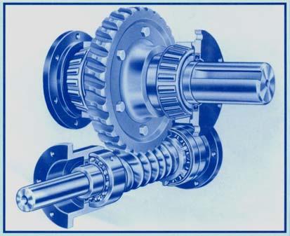
2 Fig. 2. A single stage bevel gearbox

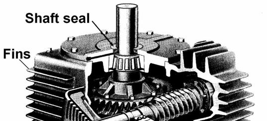
3 Fig. 4 Worm gearbox
4
5 HELICAL GEARBOX DESIGN - PROBLEM 1 In a turbine drive 300 kw power is transmitted using a pair of double helical gear. The pinion speed is 2950 rpm and that of the gear is about rpm. There are no space constraints on the gear drive. Selecting suitable materials, design the pinion and the gear to last for 10 8 cycles. Design the gearbox completely. Data: W = 300kW; n 1 = 2950rpm; n rpm; Life 10 8 cycles. Solution: 1. Angular speed of the input shaft 2πn1 2π x 2950 ω1 = = = rad/ s W 1000x Torque: T1 = = = 971.6Nm ω The details of the gear design carried out are given in Table 1 and 2.
6 The final specifications of the pinion and gear are: 20 o pressure angle involute teeth with helix angle of 35 o, h a =1m n, h f =1.25m n.; i= Z 2 / Z 1 =105/29= 3.62 Table1. Gear dimensions Z m n mm d mm d a mm d b mm d r mm m t mm Pinion Gear Table 2a. Gear specifications Φ n φ t b mm p t mm p a mm Pinion 20 o o Gear 20 o o Table 2b. Gear specifications CR t CR a CR FS s b FS s H Pinion Gear


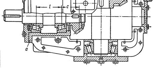
7 Fig.10a. Pinion Fig.10b.Gear All dimensions are in mm and not to scale Fig.11 A commercial double helical gearbox

8 Fig. 12 Gearbox outer dimensions (tentative)
9 4. Shaft design is based on the ASME equation: Tangential load on the shaft: F t = T/r = 971.6/ = 11kN F r =F t tan Ø =11tan23.96 o = 4.89kN F = (F t 2 + F r 2 ) 0.5 = ( ) 0.5 =15.42kN Bending moment at C M = Fl /4 =15.42x0.15/4=0.58 knm By ASME code equation for shaft design we have, d = (KbM) + (KtT) π(1 k)[ τ] k = 0.2 i.e, 20% reduction in strength due to keyway is assumed. From Table 3, for rotating shaft with minor shock loads, K b = 1.5 and K t = 1.0. Taking C45 steel for the shaft, σ yp = 360 MPa yp = 360/2 = 180 MPa and taking factor of safety of 2, [ yp] = 180/2 = 90 MPa
10 16 d = (KmM) + (K T) π(1 k)[ τ] 2 2 t 16 x10 π(1 0.2)x d = (1.5x0.58) + (1x0.9716) = 46mm Take d = 50 mm. Check for deflection at the pinion centre. Deflection at C: 3 Fl x150 δ= = = 0.017mm 4 48EI 5 πx50 48 X2.1x10 ( ) 64 Since δ < 0.01m = 0.01x5 = 0.05 mm, the design is OK. Check for slope at the bearing at A. 2 2 FL 15420x150 Slope: α= = = rad. 4 16EI 5 πx50 16x2.1x10 x( ) 64 α < rad. Hence the design is OK Check for the pinion size. The minimum pitch diameter of the pinion should be d 1min 2 x bore m where d is the bore diameter and m is the module expressed in mm. D 1min 2bore +0.1m= 2x x5 = mm Since d 1 = mm > D 1min. The design is satisfactory. Pinion drawing is shown in Fig.15 with full dimensions. 6. The outside diameter of the hubs in larger gears should be 1.8 times the bore for steel. The hub length should be at least 1.25 times the bore and never less than the width of the gear. Gear shaft diameter = d (i) 1/3 = 50 (3.62) 1/3 = 77 mm. Gear shaft diameter of 80 mm is taken. The hub diameter: d H = 1.8 x 80 = 144 mm, 150 mm is taken. Hub length is taken as L =1.25d =1.25 x mm Other dimensions of the gear are given in Fig. 16.

11 In view of the dimensions of the pinion and the gear, the dimensions of the shaft layout is revised as shown in Fig.17. When the calculations are redone, there is no change in shaft diameters. The same diameters are adopted for further computations. Fig.15. Pinion blank drawing showing all the dimensions. Fig.16. Gear blank drawing showing all the dimensions
12 7. Bearings selection is based on 90% reliability for the following life: 8 hrs. operation per day life= 20,000-30,000 hrs. Consider the bearings at A & B with Life = 30,000 hrs, P = / 2 = 7710 N, f n = for n = 2950 rpm from FAG catalog. f L = 3.91 for hrs life assuming 16 hrs/day working from FAG catalog. C = (f L / f n )P = (3.91/0.224)x7710 =134581N =134.6kN Giving 2.5 mm abutment for the bearings, shaft diameter of the bearing should be 45 mm. Roller bearing NJ 2309 satisfies this requirement C = 137 kn, C o = 153 kn, d o =100 mm, d i = 45mm, b = 36mm. For the gear shaft of diameter 80mm, giving abutment of 2.5 mm, bearing bore diameter should be 75mm. P = 7710 N, f n = for shaft speed of 815 rpm. P = 7710 N, f n = for shaft speed of 815 rpm. f L = 3.91 for Life of 30,000 hrs. C= (f L /f n ) x P = (3.91/.345)x 7710 = 87,380 = kn Deep groove ball bearing 6315 with C=114kN, C o =67kN; d o = 160 mm ; d i = 75mm; b=37mm.
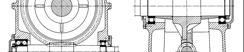
13 8. Gearbox dimensions are fixed based on thumb rule given in Table 4. Table 4. Wall thickness s in mm of the gearboxes. Non-case hardened gears Case hardened gears CI castings 0.007L + 6 mm L + 6 mm Steel castings 0.005L + 4 mm 0.007L + 4 mm Welded construction 0.004L + 4 mm 0.005L + 4 mm Where L is the largest dimension of the housing in mm. s = 0.005L + 4 mm =0.005x mm Top cover thickness: S c = 0.8s =8 mm. Flange thickness :s f = 2s = 2x10 = 20 mm Flange cover bolt diameter: d cb = 1.5s 16 mm M16 bolts. Bolt spacing: 6d = 6x mm Foundation bolt diameter: d fb =(2T) 1/3 12 mm d fb = (2x3.62x971.6) 1/3 = 19.2, Take M20 bolts. The thickness of the foundation flange should be: s ff 1.5 d fb. S ff = 1.5 d fb = 1.5x20 = 30 mm The width of the flange at the base: w b = 2.5d = 2.5 x 20 = 50 mm The width of the flanges at the two halves of the housing should be: w f = 2.5d = 2.5 x 16 = 40 With welding bead of 5mm, w f = 45 mm is taken. Outside dimension of the bearing housing times outside diameter of the bearing. Bearing housing diameters are : 1.5x100 = 150mm and : 1.3x160 = 210 mm taking 6 Nos. M10 bolts for the bearing covers. The views of the bottom and top half of the gearbox are shown in Fig. 18 and Fig.19.
14
15 RECOMMENDED OIL FOR VARIOUS SLIDING SPEEDS Table 5. Recommended oil viscosity V50 [cst at 50 o C] For different sliding speeds v(m/s) V 50 min V 50 max v(m/s) V 50 min V 50 max The gears are operating at a sliding speed of v = ωr = x = m/s. From the Table 5, the recommended oil viscosity at 50 o C for this operation is V 50 between 25 to 51 cst (interpolated values). ISO VG 100 satisfies this, see Fig. 20 The equivalent grade from chart in Fig. 21, SAE 30 oil comes under this range and is recommended for the operation.
16 ISO VG GRADE LUBRICANTS


17 SAE OIL VISCOSITY CHART 9. Losses in gear boxes : Total power loss L = L t + L ch + L b + L s L t - power loss at tooth engagement. L ch - churning power losses L b - bearing power losses & Ls-seal frictional power loss.
18 Lt = W + kw Z1 cosψ V Lt = kW O = 29cos Vµ 3 Lch = cbv x10 kw Z1 Z + 2 Where V - peripheral speed ( m/s) b - face width of the gear ( mm ) c - factor equal to for splash lubrication, µ - viscosity of oil at the operating temperature ( cp ) for stream lubrication Vµ 3 Lch = cbv x10 kw Z1+ Z x27.3x35 3 Lch = 0.006x70x27.3x x10 = kw Lb = 5.23 x 10⁻⁸ F f b d n kw where F - radial load on the bearing ( N ) f b - coefficient of friction at the bearing reduced to the shaft diameter for rough estimation or refer to catalog. d - shaft diameter ( mm ) n - shaft speed ( rpm ) From the catalog f B = for roller bearings and for ball bearings. Bearings at A & B L b = 5.23 x 10⁻⁸ F f b d n = 5.33x10-8x 15420x0.002 x 45x2950 =0.218 kw Bearings at D & E L b = 5.23 x 10⁻⁸ F f b d n = 5.33x10-8 x 15420x0.003 x75x814.92= 0.151kW L B = kw
 1/3 φ = Characteristic Number µ = Oil Viscosity [N.")
19 Seal frictional power loss: L s = T s ω x10-3 kw Where T s seal friction torque ω angular velocity of the shaft. T s = f P r r Where r = radius of the shaft [m] f seal friction P r Radial lip load [N] Coefficient of friction: f f= φ(µ v b / P r ) 1/3 φ = Characteristic Number µ = Oil Viscosity [N.s/cm 2 ] v = Linear Speed [m/s] b = Lip Contact Width [m] Fig. 22 gives the torque vs temperature chart for seal. Let the outlet oil temperature be 65 o C At 65 o C, T s =0.17Nm from Fig.23. V = πdn/60000 = πx50x1000/60000 = 2.36 m/s The operating Velocity V = πx45x2950/60000 = 6.95 m/s T s at operating speed of pinion shaft speed = 0.17x(6.95/2.36) 1/3 =0.244 Nm
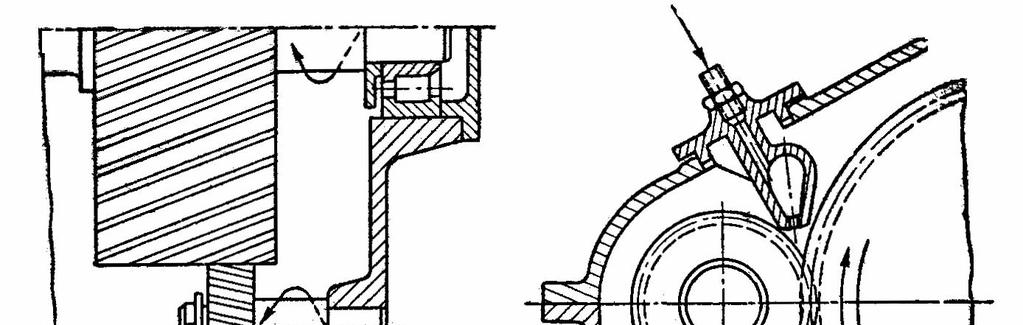
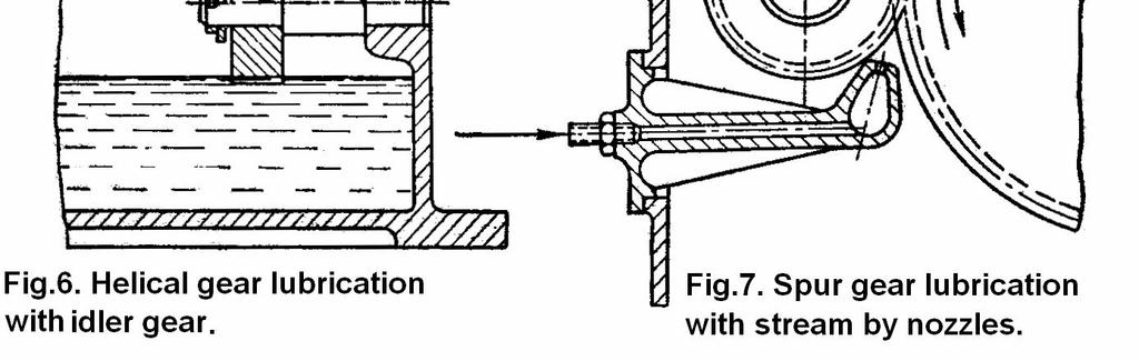
20 Pinion shaft seals power loss L s = T s ω x10-3 = 0.244x x 2 x10-3 = kw Gear shaft seal power loss V = π x 75x814.92/60000 = 3.2 m/s T s = 0.17 ( 3.2/2.36) 1/3 = Nm L s = T s ω x10-3 = (308.77/3.62)x2x10-3 = kw Total seal friction = = kw. Total power loss in the gearbox: L = L t + L ch + L b + L s = = kw For the operating speed of the gear m/s suggested type of lubrication is oil jet lubrication. Assuming inlet oil temperature of 40 o C and outlet oil temperature of 65 o C, the oil supply rate has to be: Q e = L x 10 3 / ρ c T = (5.315x10 3 / 0.88x1670x25) = lps = x60 =8.68 lpm. Based the details of the gearbox the shaft details are worked out and detailed pinion shaft drawing is shown in Fig. 24 and that of the gear shaft in Fig.25. The corresponding revised dimensions of the gears are shown in Fig.26 and 27.
21 Fig. 26. Pinion blank revised drawing showing all the dimensions.
22 Fig. 27. Gear blank revised drawing showing all the dimensions. Details of the gearbox Table 6. Gearbox size & wt Pinion C45 steel with hardness 380 Bhn Hobbed and ground 745x260x1020 mm 330 kg Gear ductile iron grade 120/90/02 of hardness 331 Bhn Hobbed and ground MS welded construction Shafts C-45 hardened and tempered and ground Lubricant SAE 30 Oil jet lubrication 10 lpm η = 98.2% The gearbox is of split type with radial assembly. Gears and bearings are mounted on the shafts separately outside and assembled radially in the gearbox and the top cover is bolted in position. The oil jet and the outlet connections are made subsequently. 8 lpm oil is directed at the gear mesh and 2 lpm is directed at the bearings and seals. The gearbox assembly views are shown in Fig. 28 to 30. Fig.28 shows the front view separately, Fig.29. The end view end view separately for clarity. and Fig.30 shows the complete view front and side together.
23
24
Sheet 1 Variable loading
 Sheet 1 Variable loading 1. Estimate S e for the following materials: a. AISI 1020 CD steel. b. AISI 1080 HR steel. c. 2024 T3 aluminum. d. AISI 4340 steel heat-treated to a tensile strength of 1700 MPa.
Tooth thickness Dedendum. Addendum. Centre distance Nominal
 FORMULAS SPUR GEARS TO FIND:- PCD ØD MODULE No. of TEETH CP ADDENDUM DEDENDUM MODULE No. of TEETH x MOD (mm) (No. of TEETH + ) x MOD (mm) 5.4 MODULE CP π (mm) PCD MODULE (mm) MODULE x π (mm) MODULE (mm)
QUESTION BANK Chapter:-6 Design of IC Engine Components
 QUESTION BANK Chapter:-6 Design of IC Engine Components Que:-1 Design a cast iron piston for a single acting four stroke diesel engine for following data: Cylinder bore = 100 mm, stroke = 125 mm, Pmax
Chapter 1 Gear Design
 Chapter 1 Gear Design GTU Paper Analysis Sr. No. Questions Nov 16 May 17 Nov 17 May 18 Theory 1. Explain the following terms used in helical gears: (a) Helix angle; (b) Normal pitch; (c) Axial pitch; (d)
Bevel Gears. Fig.(1) Bevel gears
 Bevel gears") Bevel Gears Bevel gears are cut on conical blanks to be used to transmit motion between intersecting shafts. The simplest bevel gear type is the straighttooth bevel gear or straight bevel gear as can be
Bevel Gears Bevel gears are cut on conical blanks to be used to transmit motion between intersecting shafts. The simplest bevel gear type is the straighttooth bevel gear or straight bevel gear as can be
 DEPARTMENT OF MECHANICAL ENGINEERING Subject code: ME6601 Subject Name: DESIGN OF TRANSMISSION SYSTEMS UNIT-I DESIGN OF TRANSMISSION SYSTEMS FOR FLEXIBLE ELEMENTS 1. What is the effect of centre distance
Bevel Gears n A Textbook of Machine Design
 080 n A Textbook of Machine Design C H A P T E R 30 Bevel Gears. Introduction.. Classification of Bevel Gears. 3. Terms used in Bevel Gears. 4. Determination of Pitch Angle for Bevel Gears. 5. Proportions
KINGS COLLEGE OF ENGINEERING DEPARTMENT OF MECHANICAL ENGINEERING
 KINGS COLLEGE OF ENGINEERING DEPARTMENT OF MECHANICAL ENGINEERING QUESTION BANK Sub Code/Name: ME 1352 DESIGN OF TRANSMISSION SYSTEMS Year/Sem: III / VI UNIT-I (Design of transmission systems for flexible
CONTENT. 1. Syllabus 2. Introduction 3. Shaft 4. Coupling. Rigid coupling. Flange coupling. Sleeve (or) muff coupling Split muff coupling
 muff coupling Split muff coupling") UNIT II 1. Syllabus 2. Introduction 3. Shaft 4. Coupling Rigid coupling CONTENT Flange coupling Protected flange coupling Unprotected flange coupling Marine type flange coupling Sleeve (or) muff coupling
UNIT II 1. Syllabus 2. Introduction 3. Shaft 4. Coupling Rigid coupling CONTENT Flange coupling Protected flange coupling Unprotected flange coupling Marine type flange coupling Sleeve (or) muff coupling
CH#13 Gears-General. Drive and Driven Gears 3/13/2018
 CH#13 Gears-General A toothed wheel that engages another toothed mechanism in order to change the speed or direction of transmitted motion The gear set transmits rotary motion and force. Gears are used
Design and Analysis of Six Speed Gear Box
 Design and Analysis of Six Speed Gear Box Ujjayan Majumdar 1, Sujit Maity 2, Gora Chand Chell 3 1,2 Student, Department of Mechanical Engineering, Jalpaiguri Government Engineering College, Jalpaiguri,
Chapter 8 Kinematics of Gears
 Chapter 8 Kinematics of Gears Gears! Gears are most often used in transmissions to convert an electric motor s high speed and low torque to a shaft s requirements for low speed high torque: Speed is easy
EXAMPLES GEARS. page 1
 (EXAMPLES GEARS) EXAMPLES GEARS Example 1: Shilds p. 76 A 20 full depth spur pinion is to trans mit 1.25 kw at 850 rpm. The pinion has 18 teeth. Determine the Lewis bending stress if the module is 2 and
NME-501 : MACHINE DESIGN-I
 Syllabus NME-501 : MACHINE DESIGN-I UNIT I Introduction Definition, Design requirements of machine elements, Design procedure, Standards in design, Selection of preferred sizes, Indian Standards designation
Design and Fabrication of Mini Saw Cotton Ginning Machine
 IJIRST International Journal for Innovative Research in Science & Technology Volume 3 Issue 03 August 2016 ISSN (online): 2349-6010 Design and Fabrication of Mini Saw Cotton Ginning Machine Bhushan S.
PRECISION GROUND GEARS Spur & Helical Gears
 Spur & Helical Gears Description Symbol Unit Equation Normal Module m n Transverse Module m t = m n / cos b Axial Module m x = m n / sin b Normal Pressure Angle a n degrees = 2 Transverse Pressure Angle
Civil Engineering Hydraulics. Radial Flow Devices
 Civil Engineering Hydraulics 2 3 Many rotary-flow devices such as centrifugal pumps and fans involve flow in the radial direction normal to the axis of rotation and are called radial- flow devices. 4 In
1.6 Features of common gears
 1.6 Features of common gears Chapter 1.2 covered briefly on types of gear. The main gear features are explained here. Helical gear Helical gear has characteristics of transferability of larger load, less
THEORY OF MACHINES FRICTION CLUTCHES
 THEORY OF MACHINES FRICTION CLUTCHES Introduction A friction clutch has its principal application in the transmission of power of shafts and machines which must be started and stopped frequently. Its application
NODIA AND COMPANY. Model Test Paper - I GATE Machine Design. Copyright By Publishers
 No part of this publication may be reproduced or distributed in any form or any means, electronic, mechanical, photocopying, or otherwise without the prior permission of the author. Model Test Paper -
Mechanism Feasibility Design Task
 Mechanism Feasibility Design Task Dr. James Gopsill 1 Contents 1. Last Week 2. Types of Gear 3. Gear Definitions 4. Gear Forces 5. Multi-Stage Gearbox Example 6. Gearbox Design Report Section 7. This Weeks
Transmissions. Pat Willoughby Wednesday Section 2/16/2005
 Transmissions Pat Willoughby Wednesday Section /6/005 Strategies -> Concepts -> Modules Strategies (What are you going to do?) Basic movements on table, how you will score Analysis of times to move, physics
Chapter 3. Transmission Components
 Chapter 3. Transmission Components The difference between machine design and structure design An important design problem in a mechanical system is how to transmit and convert power to achieve required
Highest Performance: Dyna Series
 Highest Performance: Dyna Series GAM can. If you don t see exactly what you need, let us know. We can modify the Dyna Series gearboxes to meet your needs. Page provides a list of commonly requested modifications
Chain Drives. Pitch. Basic Types -There are six major types of power-
 1 2 Power transmission chains have two things in common; side bars or link plates, and pin and bushing joints. The chain articulates at each joint to operate around a toothed sprocket. The pitch of the
The Sommerfeld number is also a dimensionless parameter used extensively in the design of
 Critical Pressure of the Journal Bearing The pressure at which the oil film breaks down so that metal to metal contact begins, is known as critical pressure or the minimum operating pressure of the bearing.
Introduction. Kinematics and Dynamics of Machines. Involute profile. 7. Gears
 Introduction The kinematic function of gears is to transfer rotational motion from one shaft to another Kinematics and Dynamics of Machines 7. Gears Since these shafts may be parallel, perpendicular, or
CHENDU COLLEGE OF ENGINEERING & TECHNOLOGY DEPARTMENT OF MECHANICAL ENGINEERING QUESTION BANK
 CHENDU COLLEGE OF ENGINEERING & TECHNOLOGY DEPARTMENT OF MECHANICAL ENGINEERING QUESTION BANK Sub Code: ME 2342 DESIGN OF TRANSMISSION SYSTEM UNIT - I 1. How the bevel gears are classified? Explain with
Electric Motors and Drives
 EML 2322L MAE Design and Manufacturing Laboratory Electric Motors and Drives To calculate the peak power and torque produced by an electric motor, you will need to know the following: Motor supply voltage:
Hoist Brake Motor. Hoist Gearbox Reeving Wire Rope Construction
 DR11 Monorail Hoist Hoist Brake Motor Hoist Gearbox Reeving Wire Rope Construction Rope Drum Trolley Brake Motor Trolley gearbox Trolley Trolley Wheels Load Block Hoist VFD Controls Trolley VFD Controls
Power Transmission Elements II: Gears and Bearings. Lecture 3, Week 4
 Power Transmission Elements II: Gears and Bearings Lecture 3, Week 4 Announcements Lab 4 need to finish by Friday Friday lab can get started today Project proposal Due at 23:59 tonight Email to us: matthewg@mit.edu,
ISSN: [Mukherjee * et al., 6(9): September, 2017] Impact Factor: 4.116
![ISSN: [Mukherjee * et al., 6(9): September, 2017] Impact Factor: 4.116](/thumbs/82/86563818.jpg "ISSN: [Mukherjee * et al., 6(9): September, 2017] Impact Factor: 4.116") IC Value:.00 IJESRT INTERNATIONAL JOURNAL OF ENGINEERING SCIENCES & RESEARCH TECHNOLOGY DESIGN AND ANALYSIS OF POWER TRAIN SYSTEM OF HEAVY TRUCK ENGINE Sabyasachi Mukherjee* & Puspendu Chandra Assistant
IC Value:.00 IJESRT INTERNATIONAL JOURNAL OF ENGINEERING SCIENCES & RESEARCH TECHNOLOGY DESIGN AND ANALYSIS OF POWER TRAIN SYSTEM OF HEAVY TRUCK ENGINE Sabyasachi Mukherjee* & Puspendu Chandra Assistant
The University of Melbourne Engineering Mechanics
 The University of Melbourne 436-291 Engineering Mechanics Tutorial Twelve General Plane Motion, Work and Energy Part A (Introductory) 1. (Problem 6/78 from Meriam and Kraige - Dynamics) Above the earth
Shafts are usually available up to 7 meters length due to inconvenience in transport. In order to have a greater length, it becomes necessary to join
 Design of shaft Shafts are usually available up to 7 meters length due to inconvenience in transport. In order to have a greater length, it becomes necessary to join two or more pieces of the shaft by
Chapter seven. Gears. Laith Batarseh
 Chapter seven Gears Laith Batarseh Gears are very important in power transmission between a drive rotor and driven rotor What are the functions of gears? - Transmit motion and torque (power) between shafts
Hours / 100 Marks Seat No.
 17610 16172 4 Hours / 100 Seat No. Instructions (1) All Questions are Compulsory. (2) Answer each next main Question on a new page. (3) Illustrate your answers with neat sketches wherever necessary. (4)
High Pressure Gear Pumps KP 5
 High Pressure Gear Pumps KP 5 Construction 1 6 2 9 8 4 5 7 3 1 Housing 2 Gearing 3 Drive shaft end 4 Flange cover 5 Roller bearing 6 Sliding plates 7 Lip-type shaft seal 8 Plain bearing 9 Housing gasket
Friction Calculation and Simulation of Column Electric Power Steering System
 Friction Calculation and Simulation of Column Electric Power Steering System Seyed Hamid Mirmohammad Sadeghi, Raffaella Sesana, Daniela Maffiodo Abstract This study presents a procedure for friction calculation
HepcoMotion MHD Heavy Duty Track Roller Guidance System
 Motion Without Limits HepcoMotion MHD Heavy Duty Track Roller Guidance System product overview The HepcoMotion MHD system provides an accurate, durable and low friction linear guide which is particularly
Helical Gears. Section Contents
 Section Contents CATALOG NUMER / DIMENSIONS... 64-65 SELECTION PROCEDURE... 66 HORSEPOWER & TORQUE RATINGS... 67-68 STOCK ALTERED / CUSTOM HELICAL GEARS... 3-5 HELICAL GEAR ENGINEERING INFORMATION... 308-314
Methodology for Designing a Gearbox and its Analysis
 Methodology for Designing a Gearbox and its Analysis Neeraj Patel, Tarun Gupta B.Tech, Department of Mechanical Engineering, Maulana Azad National Institute of Technology, Bhopal, India. Abstract Robust
Studying the Positioning Accuracy
 Ball Screw Studying the Positioning Accuracy Causes of Error in the Positioning Accuracy Point of Selection Studying the Positioning Accuracy The causes of error in the positioning accuracy include the
High Tech High Top Hat Technicians. Gearbox Design as Seen Through the Toughbox. Gear Up
 High Tech High Top Hat Technicians Gearbox Design as Seen Through the Toughbox Or Gear Up Toughbox Gear Pairs Diametral Pitch (DP): 20 per inch Pressure angle: 14.5 degrees Gear Teeth 14 50 16 48 19 45
TXV - Characteristics
 TXV - Characteristics TXV pumps are available in 11 models from to 150 cc/rev maximum displacement. Pump reference Direction of rotation Maximum displac. (1) Max. operating pressure Max. peak pressure
STRUCTURAL AND THERMAL ANALYSIS OF GEAR TECHNOLOGY
 STRUCTURAL AND THERMAL ANALYSIS OF GEAR TECHNOLOGY D.Ashokkumar 1, M.Venkaiah 2 1 M.tech student, Mechanical Engineering, Narasaraopeta Engineering College, A.P, India 2 Assistant Professor, Mechanical
D E X Series. Extruder Gear Box. Dharam Power Transmission Equipments Pvt. Ltd.
 D E X Series Extruder Gear Box Dharam Power Transmission Equipments Pvt. Ltd. General Description Omex' DEX-Series Extruder Gearbox in double reduction parallel shaft horizontal and vertical models are
Ch# 11. Rolling Contact Bearings 28/06/1438. Rolling Contact Bearings. Bearing specialist consider matters such as
 Ch# 11 Rolling Contact Bearings The terms rolling-contact bearings, antifriction bearings, and rolling bearings are all used to describe the class of bearing in which the main load is transferred through
12/6/2013 9:09 PM. Chapter 13. Gears General. Dr. Mohammad Suliman Abuhaiba, PE
 Chapter 13 Gears General 1 2 Chapter Outline 1. Types of Gears 2. Nomenclature 3. Conjugate Action 4. Involute Properties 5. Fundamentals 6. Contact Ratio 7. Interference 8. The Forming of Gear Teeth 9.
CHAPTER 5 PREVENTION OF TOOTH DAMAGE IN HELICAL GEAR BY PROFILE MODIFICATION
 90 CHAPTER 5 PREVENTION OF TOOTH DAMAGE IN HELICAL GEAR BY PROFILE MODIFICATION 5.1 INTRODUCTION In any gear drive the absolute and the relative transmission error variations normally increases with an
BEARINGS The lower bearing assemble is constructed to allow continuous operation when fully submerged in wastewater.
 GENERAL SPECIFICATION INTENT The equipment to be supplied by manufacturer includes the screw pumps, support for the drive unit, profile plates, motors, gearboxes, couplings, guards, upper and lower bearing
Spur gearing, Helical gearing [mm/iso] Pinion Gear ii Project information? i Calculation without errors.
![Spur gearing, Helical gearing [mm/iso] Pinion Gear ii Project information? i Calculation without errors.](/thumbs/80/81955134.jpg "Spur gearing, Helical gearing [mm/iso] Pinion Gear ii Project information? i Calculation without errors.") S Spur gearing, Helical gearing [mm/iso] i Calculation without errors. Pinion Gear ii Project information? Input section 1. Options of basic input parameters 1.1 Transferred power Pw [kw] 9.67 9.63 1.2
S Spur gearing, Helical gearing [mm/iso] i Calculation without errors. Pinion Gear ii Project information? Input section 1. Options of basic input parameters 1.1 Transferred power Pw [kw] 9.67 9.63 1.2
Design and Analysis of Spring-Ball Clutch Torque Limiter
 Design and Analysis of Spring-Ball Clutch Torque Limiter Nasiket M. Gawas, Manali S. Patkar, Prasad B. Gawade 1 B.E Student, B.E Student, 3 B.E Student Mechanical Engineering, Finolex Academy of Management
LONG LENGTH DESIGN MANUAL CONTENTS PAGE. Introduction Long Length features & benefits... 2 Long Length belting programme... 7
 DESIGN MANUAL LONG CONTENTS PAGE LENGTH Introduction Long Length features & benefits... 2 Long Length belting programme... 7 Drive Design Belt drive selection procedure... 8 Belt pitch selection guides...
PERIYAR CENTENARY POLYTECHNIC COLLEGE PERIYAR NAGAR - VALLAM THANJAVUR. DEPARTMENT OF MECHANICAL ENGINEERING QUESTION BANK
 PERIYAR CENTENARY POLYTECHNIC COLLEGE PERIYAR NAGAR - VALLAM - 613 403 - THANJAVUR. DEPARTMENT OF MECHANICAL ENGINEERING QUESTION BANK Sub : Design of Machine Elementss Year / Sem: III/ V Sub Code : MEB
Part VII: Gear Systems: Analysis
 Part VII: Gear Systems: Analysis This section will review standard gear systems and will provide the basic tools to perform analysis on these systems. The areas covered in this section are: 1) Gears 101:
COUPLINGS HRC FLEXIBLE COUPLINGS CHAIN SHAFT COUPLINGS SPLINE CLUTCHES TORQUE LIMITERS TORQUE LIMITER COUPLINGS
 COUPLINGS HRC FLEXIBLE COUPLINGS CHAIN SHAFT COUPLINGS SPLINE CLUTCHES TORQUE LIMITERS TORQUE LIMITER COUPLINGS FLEXIBLE COUPLINGS HRC TYPE Hercus HRC Couplings are designed for general-purpose applications
RS & RT WORM GEAR BOXES
 RS & RT WORM GEAR BOXES C-MRS-MRT ed0-2009 rev00 GB Product Description Multipurpose housing Aluminium die cast & Grey Iron Modular for all mountings Wormshaft ZI profile, hardened and ground. Alloy steel.
Expansion Joint Ball Joint Flexible Joint
 Ball Joint Flexible Joint -1 Step 0 Type/Structure/Features Please refer to this for structure and feature of Expansion Joint, Ball Joint, and Flexible Joint. Step 1 Selection Please look at the ID chart
ME6401 KINEMATICS OF MACHINERY UNIT- I (Basics of Mechanism)
") ME6401 KINEMATICS OF MACHINERY UNIT- I (Basics of Mechanism) 1) Define resistant body. 2) Define Link or Element 3) Differentiate Machine and Structure 4) Define Kinematic Pair. 5) Define Kinematic Chain.
ME6401 KINEMATICS OF MACHINERY UNIT- I (Basics of Mechanism) 1) Define resistant body. 2) Define Link or Element 3) Differentiate Machine and Structure 4) Define Kinematic Pair. 5) Define Kinematic Chain.
DESIGNING OF THE RACK AND PINION GEARBOX FOR ALL TERRAIN VEHICLE FOR THE COMPETITION BAJA SAE INDIA AND ENDURO STUDENT INDIA
 DESIGNING OF THE RACK AND PINION GEARBOX FOR ALL TERRAIN VEHICLE FOR THE COMPETITION BAJA SAE INDIA AND ENDURO STUDENT INDIA Omkar Diliprao Suryavanshi 1, Prathmesh Prasad Sathe 2, Mahesh Ashokrao Takey
ME6601 DESIGN OF TRANSMISSION SYSTEMS
 SYED AMMAL ENGINEERING COLLEGE (Approved by the AICTE, New Delhi, Govt. of Tamilnadu and Affiliated to Anna University, Chennai) Established in 1998 - An ISO 9001:2008 Certified Institution Dr. E.M.Abdullah
EFFICIENCY PERFECTED. DYNAGEAR DG ECOSYSTEM - FORCES AND SPEEDS with helical teeth and ratio i=5. Feed force [N] Feed speed [m/s]
![EFFICIENCY PERFECTED. DYNAGEAR DG ECOSYSTEM - FORCES AND SPEEDS with helical teeth and ratio i=5. Feed force [N] Feed speed [m/s]](/thumbs/72/67540751.jpg "EFFICIENCY PERFECTED. DYNAGEAR DG ECOSYSTEM - FORCES AND SPEEDS with helical teeth and ratio i=5. Feed force [N] Feed speed [m/s]") EFFICIENCY PERFECTED DYNAGEAR DG ECOSYSTEM - FORCES AND SPEEDS with helical teeth and ratio i=5 2000 TEETH RATIO i = 5 Feed force [N] 0000 8000 6000 4000 DE-DG5 m4 DE-DG5 m DE-DG90 m DE-DG90 m2 DE-DG75
EFFICIENCY PERFECTED DYNAGEAR DG ECOSYSTEM - FORCES AND SPEEDS with helical teeth and ratio i=5 2000 TEETH RATIO i = 5 Feed force [N] 0000 8000 6000 4000 DE-DG5 m4 DE-DG5 m DE-DG90 m DE-DG90 m2 DE-DG75
Chapter 11. Keys, Couplings and Seals. Keys. Parallel Keys
 Chapter 11 Keys, Couplings and Seals Material taken for Keys A key is a machinery component that provides a torque transmitting link between two power-transmitting elements. The most common types of keys
SHAFT MOUNTED HELICAL GEAR REDUCER
 Shaft Mounted Helical Gear Assembly INTRODUCTION The VIGNESSH Shaft Mounted Helical Gear Units are the result of experience in design and production, taking advantage of the most recent relevent research
Design and Manufacturing of Portal Axle Gear Box
 Volume: 04 Issue: 04 pr -2017 www.irjet.net p-issn: 2395-0072 Design and Manufacturing of Portal xle Gear ox Mali Lakhan. 1, Supekar Dattatray Dilip 2, Sayyad rshad Jabbar 3, Sartape Sandesh Laxman 4 Taware
UNIT -I. Ans: They are specified by the no. of strands & the no. of wires in each strand.
 VETRI VINAYAHA COLLEGE OF ENGINEERING AND TECHNOLOGY, THOTTIAM, NAMAKKAL-621215. DEPARTMENT OF MECHANICAL ENGINEERING SIXTH SEMESTER / III YEAR ME6601 DESIGN OF TRANSMISSION SYSTEM (Regulation-2013) UNIT
Introduction to Gear Design
 Introduction to Gear Design Course No: M03-016 Credit: 3 PDH Robert P. Tata, P.E. Continuing Education and Development, Inc. 9 Greyridge Farm Court Stony Point, NY 10980 P: (877) 322-5800 F: (877) 322-4774
Design and Vibrational Analysis of Flexible Coupling (Pin-type)
") Design and Vibrational Analysis of Flexible Coupling (Pin-type) 1 S.BASKARAN, ARUN.S 1 Assistant professor Department of Mechanical Engineering, KSR Institute for Engineering and Technology, Tiruchengode,
Design and Vibrational Analysis of Flexible Coupling (Pin-type) 1 S.BASKARAN, ARUN.S 1 Assistant professor Department of Mechanical Engineering, KSR Institute for Engineering and Technology, Tiruchengode,
International Journal of Advance Engineering and Research Development. Design of Two Stage Planetary Gear Train for High Reduction Ratio
 Scientific Journal of Impact Factor (SJIF): 4.72 International Journal of Advance Engineering and Research Development Volume 5, Issue 01, January -2018 e-issn (O): 2348-4470 p-issn (P): 2348-6406 Design
Gear Engineering Data. Spur Gear Gear Formulas Drive Selection Horsepower and Torque Tables
 Engineering Gear Engineering Data Spur Gear Gear Formulas Drive Selection Horsepower and Torque Tables G-79 Gear Selection Stock Spur Gear Drive Selection When designing a stock gear drive using the horsepower
High Pressure Gear Motors KM 5
 High Pressure Gear Motors KM 5 2 KRACHT GmbH Gewerbestr. 20 58791 Werdohl, Germany fon +49(0)2392/935-0 fax +49(0)2392/935 209 mail info@kracht.eu web www.kracht.eu Construction 1 Housing 2 Gearing 3 Drive
Effect of Geometry Factor I & J Factor Multipliers in the performance of Helical Gears
 Effect of Geometry Factor I & J Factor Multipliers in the performance of Helical Gears 1 Amit D. Modi, 2 Manan B. Raval, 1 Lecturer, 2 Lecturer, 1 Department of Mechanical Engineering, 2 Department of
Linear Actuator with Ball Screw Series OSP-E..S. Contents Description Overview Technical Data Dimensions 79
 Linear Actuator with Ball Screw Series OSP-E..S Contents Description Page Overview 71-74 Technical Data 75-78 Dimensions 79 71 The System Concept ELECTRIC LINEAR ACTUATOR FOR HIGH ACCURACY APPLICATIONS
PARALLEL INDEX DRIVES TP Series
 PARALLEL INDEX DRIVES TP Series Calculations J = moment of inertia Application examples Direct driven belt/chain = M B + M B M B = c a n 2π n x t² M R = µ g R m = M B + M R + (M ST )* M ST = m g R M AN
TECHNICAL INFORMATION
 General Nomenclature Spherical Roller Bearings The spherical roller bearing is a combination radial and thrust bearing designed for taking misalignment under load When loads are heavy, alignment of housings
Power transmission. Components used to transmit power: gears, belt, clutch and brakes. Gear (Stresses) act on the tooth Lewis formula and AGMA
 act on the tooth Lewis formula and AGMA") 1 Power transmission Components used to transmit power: gears, belt, clutch and brakes. Failure Types Gear (Stresses) Bending: resulted from bending stress. t act on the tooth Lewis formula and AGMA Pitting:
1 Power transmission Components used to transmit power: gears, belt, clutch and brakes. Failure Types Gear (Stresses) Bending: resulted from bending stress. t act on the tooth Lewis formula and AGMA Pitting:
SCM M2. Other advantages:
 Sunfab s SCM 025-108 M2 is a range of robust axial piston motors with cartridge flange especially suitable for winch-, slewing-, wheel- and track drives. SCM 025-108 M2 is of the bent-axis type with spherical
Design and Analysis of High Speed Helical Gear By Using Ansys
 Design and Analysis of High Speed Helical Gear By Using Ansys A. Sai Bharath*1, T.v.s.r.k. Prasad*2 M.Tech Student (Cad/ Cam) Mechanical Engineering, NCET, Jupudi, Ibrahimpatnam, Vijayawada, Krishna (dt),a.p,
MOTOR SCM ISO
 MOTOR SCM 012-130 ISO SCM 012-130 ISO is a range of robust axial piston motors especially suitable for mobile hydraulics. SCM 012-130 ISO is of the bent-axis type with spherical pistons. The design results
VALLIAMMAI ENGINEERING COLLEGE DEPARTMENT OF MECHANICAL ENGINEERING ME6503 DESIGN OF MACHINE ELEMENTS QUESTION BANK
 VALLIAMMAI ENGINEERING COLLEGE DEPARTMENT OF MECHANICAL ENGINEERING ME6503 DESIGN OF MACHINE ELEMENTS QUESTION BANK Unit -1 STEADY STRESSES AND VARIABLE STRESSES IN MACHINE MEMBERS Part-A 1. What are the
Chapter 7. Shafts and Shaft Components
 Chapter 7 Shafts and Shaft Components 2 Chapter Outline Introduction Shaft Materials Shaft Layout Shaft Design for Stress Deflection Considerations Critical Speeds for Shafts Miscellaneous Shaft Components
General gear terms and definitions. Trantorque 48 DP. Steel and Brass
 General gear terms and definitions 317 Spur and Helical Gears: Formulae and definitions Helical Gear Spur Gear Term Definition formulae formulae 318 Spur and Helical Gears: Formulae and definitions Helical
Linear Actuator with Ball Screw Series OSP-E..S. Contents Description Overview Technical Data Dimensions 89
 Linear Actuator with Ball Screw Series OSP-E..S Contents Description Page Overview 79-82 Technical Data 83-88 Dimensions 89 79 The System Concept ELECTRIC LINEAR ACTUATOR FOR HIGH ACCURACY APPLICATIONS
Lecture (7) on. Gear Measurement. By Dr. Emad M. Saad. Industrial Engineering Dept. Faculty of Engineering. Fayoum University.
 on. Gear Measurement. By Dr. Emad M. Saad. Industrial Engineering Dept. Faculty of Engineering. Fayoum University.") 1 Lecture (7) on Gear Measurement Fayoum University By Dr. Emad M. Saad Industrial Engineering Dept. Faculty of Engineering Fayoum University Faculty of Engineering Industrial Engineering Dept. 2015-2016
1 Lecture (7) on Gear Measurement Fayoum University By Dr. Emad M. Saad Industrial Engineering Dept. Faculty of Engineering Fayoum University Faculty of Engineering Industrial Engineering Dept. 2015-2016
Series 20 Axial Piston Pumps. Technical Information
 Series 20 Axial Piston Pumps Technical Information General Description INTRODUCTION Sauer-Danfoss a world leader in hydraulic power systems has developed a family of axial piston pumps. DESCRIPTION Sauer-Danfoss
MOTOR SCM M2
 MOTOR SCM 025 108 M2 Sunfab SCM M2 is a range of robust axial piston motors especially suitable for winch-, slewing-, wheeland track drives. Sunfab SCM M2 is of the bent-axis type with spherical pistons.
Therefore, it is the general practice to test the tooth contact and backlash with a tester. Figure 19-5 shows the ideal contact for a worm gear mesh.
 19. Surface Contact Of Worm And Worm Gear There is no specific Japanese standard concerning worm gearing, except for some specifications regarding surface contact in JIS B 1741. Therefore, it is the general
Highest Precision: Dyna Series
 GAM can. Just ask! If you don t see exactly what you need, let us know. We can modify the Dyna Series gearboxes to meet your needs. Page 3 provides a list of commonly requested modifications to give you
1/2/2015 2:04 PM. Chapter 13. Gears General. Dr. Mohammad Suliman Abuhaiba, PE
 Chapter 13 Gears General 1 2 Chapter Outline 1. Types of Gears 2. Nomenclature 3. Conjugate Action 4. Involute Properties 5. Fundamentals 6. Contact Ratio 7. Interference 8. The Forming of Gear Teeth 9.
Driver Driven. InputSpeed. Gears
 Gears Gears are toothed wheels designed to transmit rotary motion and power from one part of a mechanism to another. They are fitted to shafts with special devices called keys (or splines) that ensure
Linear actuators ILA Series
 Linear Actuator ILA Series without input drive, with flange and input shaft Linear Actuator ILA Series with input drive - with 2 bevel gearmotors - with single bevel gearmotor - with helical coaxial or
SCM ISO. SCM ISO is a range of robust axial piston motors especially suitable for mobile hydraulics.
 SCM 010-130 ISO is a range of robust axial piston motors especially suitable for mobile hydraulics. SCM 010-130 ISO is of the bent-axis type with spherical pistons. The design results in a compact motor
HP High-Performance Gear Units with <2' Adjustable Backlash
 Page HP High-Performance Gear Units with
Motion Technologies Bearing Products
 Page 1 of 12 Motion Technologies Bearing Products LARGE DIAMETER BEARINGS (conventional design) o Deep groove ball to 1900mm bore page 3 o Four point contact ball to 500mm bore page 3 o Single row angular
Series 20 Axial Piston Pumps. Technical Information
 Series 20 Axial Piston Pumps Technical Information General Description INTRODUCTION Sauer-Danfoss a world leader in hydraulic power systems has developed a family of axial piston pumps. DESCRIPTION Sauer-Danfoss
Spiroid High Torque Skew Axis Gearing A TECHNICAL PRIMER F. EVERTZ, M. GANGIREDDY, B. MORK, T. PORTER & A. QUIST
 2016 Spiroid High Torque Skew Axis Gearing A TECHNICAL PRIMER F. EVERTZ, M. GANGIREDDY, B. MORK, T. PORTER & A. QUIST Table of Contents INTRODUCTION PAGE 02 SPIROID GEAR SET CHARACTERISTICS PAGE 03 BASIC
Performance: Spiral Bevel Series
 Performance: Spiral Bevel Series GAM can. If you don t see exactly what you need, let us know. We can modify the VC Series gearboxes to meet your needs. Page provides a list of commonly requested modifications
technology made in Italy
 technology made in Italy GB RD * * VS made in China Technology Made in Italy Since 1955 Varvel has been making speed reducers and variators for light industry applications. Reliable partner in power transmission
Flywheel. 776 A Textbook of Machine Design
 776 A Textbook of Machine Design C H A P T E R Flywheel 1. Introduction.. Coefficient of Fluctuation of Speed. 3. Fluctuation of Energy. 4. Maximum Fluctuation of Energy. 5. Coefficient of Fluctuation
A comparison of the gear calculation process according to Swedish and American textbooks for higher education
 World Transactions on Engineering and Technology Education Vol.6, No.1, 2007 2007 UICEE A comparison of the gear calculation process according to Swedish and American textbooks for higher education Samir