CONTENT. 1. Syllabus 2. Introduction 3. Shaft 4. Coupling. Rigid coupling. Flange coupling. Sleeve (or) muff coupling Split muff coupling
|
|
|
- Coral Poole
- 5 years ago
- Views:
Transcription
1 UNIT II
2 1. Syllabus 2. Introduction 3. Shaft 4. Coupling Rigid coupling CONTENT Flange coupling Protected flange coupling Unprotected flange coupling Marine type flange coupling Sleeve (or) muff coupling Split muff coupling
3 Flexible coupling CONTENT Bushed pin type flexible coupling Universal coupling Oldham coupling Key Crankshaft
4 Syllabus Design of solid and hollow shafts based on strength, rigidity and critical speed Design of keys, key ways and splines Design of crankshafts Design of rigid and flexible coupling. Topics: 1. Coupling 2. Key 3. Crank shaft 4. Shaft
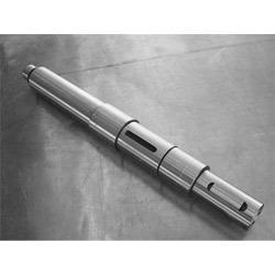
5 Introduction Shafts are usually available upto 7 metres length due to inconvenience in transport. In order to have a greater length, it becomes necessary to join two or more pieces of the shaft by means of a coupling. It is used to connect two shafts.
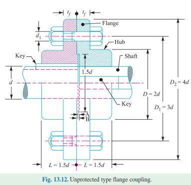
6 Flange coupling Flange coupling is a rigid coupling, it consists of two hubbed flanges. One is keyed to driving shaft and other to the driven shaft.

7 Flange Coupling
8 Continue Let d = Diameter of shaft (mm) D = Outer diameter of hub (mm) L = Length of hub in each flange (mm) d b = Diameter of bolts (mm) D p = Pitch circle diameter of bolts (mm) D o = Outer diameter of flange (mm) t f = Thickness of flange (mm) P = Power transmitted (W) N = Speed (rpm) [τ sh ] = Permissible shear stress of shaft material (N/mm 2 )
9 Continue [τ f ] = Permissible shear stress of flange material (N/mm 2 ) [τ k ] = Permissible shear stress of key material (N/mm 2 ) [τ b ] = Permissible shear stress of bolt material (N/mm 2 ) [σ cb ] = Permissible crushing stress of bolt material (N/mm 2 ) [σ ck ] = Permissible crushing stress of key material (N/mm 2 )
10 Design of Shaft and Hub Power transmitted by a solid shaft (P) P = 2πNT/60 P = Power transmitted by the shaft (Watt (or) N-m/s) T = Torque (or) twisting moment (or) Turning moment (N-m) N = Speed of the shaft (rpm) T = 16 d 3 T = Twisting moment (or) Turning moment (N-mm) [τ sh ] = Maximum shear stress (N/mm 2 ) d = Diameter of the shaft (mm) D = Diameter of hub = 2d L = Length of the hub = 1.5d sh
11 16T D Check Hub for shear τ f = N/mm d D τ f = Allowable shear stress for flange material (N/mm 2 ) T = Twisting moment (or) Turning moment (N-mm) D = Diameter of hub (mm) d = Diameter of the shaft (mm)
12 Design of Flange D o = Outer diameter of flange = 4d t f = Thickness of flange = 0.5d t p = Thickness of protected circumferential flange = 0.25d.
13 Checking flange for shear τ f = (N/mm 2 2 ) D t f τ f = Allowable shear stress for flange material (N/mm 2 ) T = Twisting moment (or) Turning moment (N-mm) 2T D = Diameter of hub (mm) t f = Thickness of flange (mm)
14 Design of Key From PSGDB: 5.16, width (w) and thickness (t)can be determined. If length of key is given assume length of the key is equal to length of hub. Length of key (l) = Length of the hub (L) Checking for shear stress: 2T l d w τ k = (N/mm 2 )
15 Checking for crushing stress σ ck = 4T (N/mm 2 ) l d t τ k = Allowable shear stress for key material, (N/mm 2 ) T = Twisting moment (or) Turning moment, N-mm l = Length of the key (mm) t = Thickness of key (mm) d =Diameter of the shaft (mm) w = Width of the key (mm)
16 Design of Bolts d b = n (mm) b d p T = Twisting moment (or) Turning moment (N-mm) d b =Diameter of bolt (mm) d p =Pitch circle diameter of bolts (mm) n = Number of bolts. 8T
17 Checking crushing for bolts σ cb = N/mm 2 d b t 2T n f σ cb = Allowable shear stress for key material (N/mm 2 ) T = Twisting moment (or) Turning moment (N-mm) d b =Diameter of bolt (mm) d p = Pitch circle diameter of bolts (mm) n = Number of bolts t f = Thickness of flange (mm) d p
18 Problems (Protected type flange) 1. Design a rigid flange coupling to connect two shafts to transmit 7.5 kw at 750 rpm. The permissible shear stress for shaft, bolt and key materials is 40 N/mm 2, Permissible crushing strength for bolt and key material is 60 N/mm 2 and permissible shear stress for flange material is 20 N/mm 2.
19 Continue Design a cast Iron (C.I) flange coupling for a mild steel shaft transmitting 90 kw at 250 rpm. The allowable shear stress in the shaft is 40 MPa and the angle of twist is not be exceed 1º in a length of 20 diameters. The allowable shear stress in the coupling bolts is 30 MPa. Note: For unprotected type flange coupling the all properties are same, except that D o = 3d.
20 Marine type Flange coupling In a marine type flange coupling the flanges are forged integral with the shafts as shown in fig. The flanges are held together by means of tapered headless bolts, numbering from 4 to 12 depending upon the diameter of shaft. The number of bolts may be chosen from the following table

21 Marine type flange coupling
22 Formula for marine type flange coupling Thickness of flange = d/3 Taper of bolt = 1 in 20 in 1 in 40 Pitch circle diameter of bolts d p = 1.6d Outside diameter of flange D o = 2d (or) 2.2d
23 Problem A marine type coupling is used to transmit 65 kw at 100 rpm. The permissible shear stress for shafts and bolts is 33 MPa and permissible crushing stress for bolts is 35 MPa. Design the coupling, assuming number of bolt used as 8.
24 Sleeve (or) Muff coupling It is the simplest type of rigid coupling, made of cast iron. It consists of a hollow cylinder whose inner diameter is the same as that of the shaft. It is fitted over the ends of the two shafts by means of a gib head key. The power is transmitted from one shaft to the other shaft by means of a key and a sleeve. It is therefore, necessary that all the elements must be strong enough to transmit the torque.
 Muff")
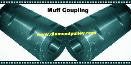
25 Sleeve (or) Muff coupling
26 Problems Design a muff (or) sleeve coupling for a shaft to transmit 35 kw at 350 rpm. The safe shear stress for the steel shaft is 50 N/mm 2 and for the cast Iron muff is 15 N/mm 2. The allowable shear and crushing stresses for the key material are 42 N/mm 2 and 120 N/mm 2 respectively. Formula D = 2d+13 mm L = 3.5d l = L/2
27 Continue STEPS: Step 1 Design of shaft diameter Step 2 Design of sleeve (or) muff Checking Step 3 Design of key Checking
28 Clamp (or) Compression (or) Split muff coupling In this case, the muff (or) sleeve is made into two halves and are bolted together. The halves of the muff are made of Cast Iron One half of the muff is fixed from below and the other half is placed above. Both the halves are held together by means of mild steel studs (or) bolts and nuts. The number of bolts may be two, four, six. This coupling may be used for heavy duty and moderate speeds.
29 Formula D = 2d+13 mm L = 3.5d l = L STEPS: Step 1 Design of shaft diameter Step 2 Design of sleeve (or) muff Checking Step 3 Design of key Checking Step 4 Design for bolts Continue
30 Problems Design a clamp coupling to transmit 30 kw at 100 rpm. The allowable shear stress for the shaft and key is 40 MPa and the number of bolts connecting the two halves are six. The permissible tensile stress for the bolts is 70 MPa. The coefficient of friction between the muff and the shaft surface may be taken as 0.3
31 Flexible Coupling A flexible coupling is used to connect two shafts which have lateral (or) angular misalignment. It is also used to reduce the effect of shock and impact load.

32 Flexible Coupling
33 Bushed Pin Type Flexible Coupling It is one type of flexible coupling. It is commonly used where the driving and driven members are mounted on a mono block. The construction of a flexible coupling is similar to that of a rigid coupling except that a rubber bushes are used over the pins as shown in fig. The coupling bolts are known as pins. The rubber (or) leather bushes are used over the pins.

34 Bushed Pin type flexible Coupling
35 Continue
36 Torque transmitted by the coupling: T W n D 2 l n 1 1 p d D b 2 Direct shear stress due to pure torsion in the coupling halves: W 4 d 1 2 Assuming a uniform distribution of the load W along the bush, the maximum bending moment on the pin: l M W 5mm 2 2

37 Bending stress: Maximum principal stress: Maximum shear stress on the pin: d mm l W Z M
38
39 Problem Design a bushed pin type of flexible coupling to connect a pump shaft to a motor shaft transmitting 32 KW at 960 rpm. The overall torque is 20 percent more than mean torque. The material properties are as follows. (a) The allowable shear and crushing stress for shaft and key material is 40 Mpa and 80 Mpa respectively. (b) The allowable shear stress for cast Iron is 15 Mpa. (c) The allowable bearing pressure for rubber bush is 0.8 N/mm 2 (d) The material of the pin is same as that of shaft and key
40
41 SHAFT: Design of shaft It is a rotating member, usually circular in cross-section used to transmit power. TRANSMISSION SHAFT: It transmit power from one place to another place. Ex. Shaft coupled with turbine. MACHINE SHAFT: Integral part of the machine. Ex. Crank shaft
42 SPINDLE: Short shaft is called spindle. Ex. Drilling machine spindle, Lathe spindle AXLE: It is appearance similar to shaft. It is load carrying member. It may be rotating (or) Non-rotating. SHAFT MATERIAL: Mild steel Cast Iron Steel-Chromium alloy Steel-Vanadium alloy Copper alloy
43 Continue STRESS INDUCED IN SHAFT MATERIAL: Shear stress due to transmission of torque Bending stress due to weight of pulley (or) gear in the shaft. Combined shear stress and Bending stress. Combined shear stress, Bending stress and axial stress.
44 Problems 1. A line shaft rotating at 300 rpm is to transmit 20 kw. Determine the diameter of the shaft, if the permissible shear stress of the shaft is 42 Mpa. Neglect bending moment on the shaft. 2. A shaft is transmitting 97.5 kw at 180 rpm. It the allowable shear stress in the material is 60MPa, find the suitable diameter for the shaft. The shaft is not to twist more than 1º in a length of 3m. Take C = 80GPa.
45 3. A solid circular shaft is subjected to a bending moment of 3000 N-m and a torque of N-m. The shaft is made of 45 C 8 steel having ultimate tensile stress of 700 MPa and a ultimate shear stress of 500 MPa. Assuming a factor of safety as 6, determine the diameter of the shaft. 4. A mild steel shaft transmits 20 kw at 200 rpm. It carries a central load of 1000 N and is simply supported between the bearing 2 m apart. Determine the size of the shaft, if the allowable shear stress is 42 MPa and maximum tensile (or) compressive stress is not to be exceed 56 MPa. What size of the shaft is required, if it is subjected to gradually applied loads?
46 5. Design a shaft to transmit power from an electric motor to a lathe head stock through a pulley by means of a belt drive. The pulley weighs 200 N and is located at 300 mm from the centre of the bearing. The diameter of the pulley is 200 mm and the maximum power transmitted is 1 kw at 120 rpm. The angle of lap of the belt is 180º and coefficient of friction between the belt and the pulley is 0.3. The shock and fatigue factors for bending and twisting are 1.5 and 2.0 respectively. The allowable shear stress in the shaft may be taken as 35 MPa.
47 6. A mild steel shaft transmit 100 kw at 300 rpm. The supported length of the shaft is 3 m. It carries two pulleys each weighting 1500 N mounted at a distance of 1m from the ends respectively. Determine the size of the shaft, if the allowable shear stress for the shaft material is 60 N/mm 2.
48 7. A mild steel shaft 900 mm between bearings support, a 600 mm pulley 300 mm to the right of the left band bearing and a belt drives the pulley directly below. Another pulley of 450 mm diameter is located 200 mm to the left of the right hand bearing and the belt is driven from a pulley horizontal to the right. The angle of contact for both the pulleys is 180º and the tension ratio is 2.2. The maximum tension in the belt on 600 mm diameter pulley is 2.25 kn. Determine the suitable diameter for the solid shaft, if the permissible tensile stress is 63 N/mm 2 and the permissible shear stress is 42 N/mm 2.
49 8. A shaft is supported on bearings A and B 800 mm between centers. A 20º straight tooth spur gear with 600 mm pitch diameter is locate 200 mm to the right of the left hand bearing A and a 700 mm diameter pulley is mounted 250 mm towards the left of bearing B. The gear is driven by a pinion with a downward tangential force while the pulley drives the horizontal belt having 180º angle of wrap. The pulley also serves as a flywheel and weight 2000 N. The maximum belt tension is 3:1. Determine the maximum bending moment and the necessary shaft diameter if the allowable shear stress of the material is 40 N/mm 2. The maximum belt tensile is 3000 N.
50 A steel solid shaft transmitting 15kW at 200 rpm is supported on two bearings 750 mm apart and has two gears keyed to it. The pinion having 30 teeth of 5 mm module is located 100 mm to the left of the right hand bearing delivers power horizontally to the right. The gear having 100 teeth of 5 mm module is located 150 mm to the right of the left hand bearing and receives power in a vertical direction from below. Using an allowable stress of 54 MPa in shear, determine the diameter of the shaft.
51 A horizontal nickel steel shaft rests on two bearings, A at the left and B at the right end and carries two gears C and D located at distances of 250 mm and 400 mm respectively from the centre line of the left and right bearings. The pitch diameter of the gear C is 600 mm and that of gear D is 200 mm. The distance between the centre line of the bearings is 240 mm.
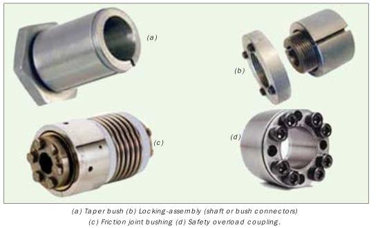
52 KEY: DESIGN OF KEYS The key is a element which is inserted between the shaft and hub of rotating element like gear (or) pulley (or) sprocket. It prevent the relative motion of a shaft and the member connected to it. Keys are used as temporary fastenings and (or) subjected to crushing and shearing. A key way is a slot provided in shaft hub of pulley (or) gear (or) sprocket to accommodate to key.
53 TYPES OF KEYS: Sunk key Saddle key Tangent key Round key Taper key splines SUNK KEY: One half portion is accommodated in the key way and that of the shaft and other half in the key way of hub.

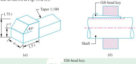
54 TYPES OF KEYS
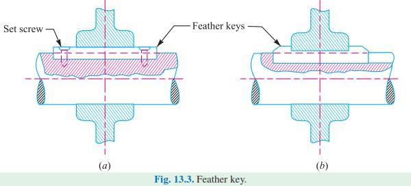
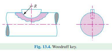
55
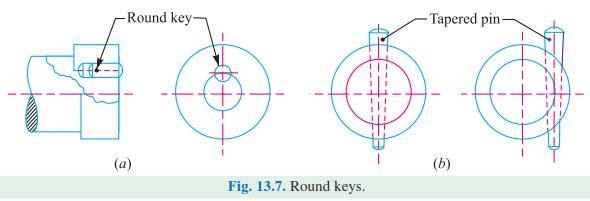
56
57 DESIGN OF SUNK KEY F 2T d Shear stress (τ k ) τ k = Force / Shearing area 2T d l w τ k = N/mm 2 Crushing stress (σ ck ) σ ck = Force / cutting area 4T d l t σ ck = N/mm 2
58 Where T Torque transmitted N-mm F Force applied N d Diameter of shaft mm l length of key mm w width of key mm t Thickness of key mm τ k Shear stress induced in key material, N/mm 2 (τ k ) Allowable (or) Permissible shear stress for key material,n/mm 2 σ ck - Crushing stress induced in key material, N/mm 2 (σ ck ) Allowable (or) Permissible crushing stress for key material, N/mm 2
59 Problem A rectangular key 40 mm length is required to transmit 10 kw at 900 rpm. Determine the size of key, if the permissible shear stress and crushing stress are limited to 65 N/mm 2 and 110 N/mm 2 respectively. Assume that the shaft and key are made of same material. (April/2010)
60 END
Shafts are usually available up to 7 meters length due to inconvenience in transport. In order to have a greater length, it becomes necessary to join
 Design of shaft Shafts are usually available up to 7 meters length due to inconvenience in transport. In order to have a greater length, it becomes necessary to join two or more pieces of the shaft by
NME-501 : MACHINE DESIGN-I
 Syllabus NME-501 : MACHINE DESIGN-I UNIT I Introduction Definition, Design requirements of machine elements, Design procedure, Standards in design, Selection of preferred sizes, Indian Standards designation
DESIGN OF MACHINE MEMBERS - I
 R10 Set No: 1 III B.Tech. I Semester Regular and Supplementary Examinations, December - 2013 DESIGN OF MACHINE MEMBERS - I (Mechanical Engineering) Time: 3 Hours Max Marks: 75 Answer any FIVE Questions
DEPARTMENT OF MECHANICAL ENGINEERING
 DEPARTMENT OF MECHANICAL ENGINEERING UABMCC01-DESIGN OF MACHINE ELEMENTS QUESTION BANK Prepared By: Dr.S.Prabhakaran, Associate Professor/Mechanical Engg. Unit -1 STEADY STRESSES AND VARIABLE STRESSES
VALLIAMMAI ENGINEERING COLLEGE DEPARTMENT OF MECHANICAL ENGINEERING ME6503 DESIGN OF MACHINE ELEMENTS QUESTION BANK
 VALLIAMMAI ENGINEERING COLLEGE DEPARTMENT OF MECHANICAL ENGINEERING ME6503 DESIGN OF MACHINE ELEMENTS QUESTION BANK Unit -1 STEADY STRESSES AND VARIABLE STRESSES IN MACHINE MEMBERS Part-A 1. What are the
Design and Vibrational Analysis of Flexible Coupling (Pin-type)
") Design and Vibrational Analysis of Flexible Coupling (Pin-type) 1 S.BASKARAN, ARUN.S 1 Assistant professor Department of Mechanical Engineering, KSR Institute for Engineering and Technology, Tiruchengode,
Design and Vibrational Analysis of Flexible Coupling (Pin-type) 1 S.BASKARAN, ARUN.S 1 Assistant professor Department of Mechanical Engineering, KSR Institute for Engineering and Technology, Tiruchengode,
DESIGN OF MACHINE ELEMENTS UNIVERSITY QUESTION BANK WITH ANSWERS. Unit 1 STEADY STRESSES AND VARIABLE STRESSES IN MACHINE MEMBERS
 DESIGN OF MACHINE ELEMENTS UNIVERSITY QUESTION BANK WITH ANSWERS Unit 1 STEADY STRESSES AND VARIABLE STRESSES IN MACHINE MEMBERS 1.Define factor of safety. Factor of safety (FOS) is defined as the ratio
DESIGN OF MACHINE MEMBERS I ASSIGNMENT
 SHRI VISHNU ENGINEERING COLLEGE FOR WOMEN DESIGN OF MACHINE MEMBERS I ASSIGNMENT UNIT I 1 a). Draw stress strain diagram for the ductile and brittle material and compare them? show the salient points on
PERIYAR CENTENARY POLYTECHNIC COLLEGE PERIYAR NAGAR - VALLAM THANJAVUR. DEPARTMENT OF MECHANICAL ENGINEERING QUESTION BANK
 PERIYAR CENTENARY POLYTECHNIC COLLEGE PERIYAR NAGAR - VALLAM - 613 403 - THANJAVUR. DEPARTMENT OF MECHANICAL ENGINEERING QUESTION BANK Sub : Design of Machine Elementss Year / Sem: III/ V Sub Code : MEB
Chapter 11. Keys, Couplings and Seals. Keys. Parallel Keys
 Chapter 11 Keys, Couplings and Seals Material taken for Keys A key is a machinery component that provides a torque transmitting link between two power-transmitting elements. The most common types of keys
Sheet 1 Variable loading
 Sheet 1 Variable loading 1. Estimate S e for the following materials: a. AISI 1020 CD steel. b. AISI 1080 HR steel. c. 2024 T3 aluminum. d. AISI 4340 steel heat-treated to a tensile strength of 1700 MPa.
EXAMPLES GEARS. page 1
 (EXAMPLES GEARS) EXAMPLES GEARS Example 1: Shilds p. 76 A 20 full depth spur pinion is to trans mit 1.25 kw at 850 rpm. The pinion has 18 teeth. Determine the Lewis bending stress if the module is 2 and
 DEPARTMENT OF MECHANICAL ENGINEERING Subject code: ME6601 Subject Name: DESIGN OF TRANSMISSION SYSTEMS UNIT-I DESIGN OF TRANSMISSION SYSTEMS FOR FLEXIBLE ELEMENTS 1. What is the effect of centre distance
NODIA AND COMPANY. Model Test Paper - I GATE Machine Design. Copyright By Publishers
 No part of this publication may be reproduced or distributed in any form or any means, electronic, mechanical, photocopying, or otherwise without the prior permission of the author. Model Test Paper -
DARSHAN INSTITUTE OF ENGG. & TECH.
 DARSHAN INSTITUTE OF ENGG. & TECH. B.E. Semester V Design of Machine Elements (2151907) Batch: Roll No.: List of Assignments Sr. No. Title Start Date End Date Sign Remark 1. Introduction 2. Design against
EXAMPLES INTRODUCTION
 AMEM 316 (AUTO308): Machine Elements I EXAMPLES INTRODUCTION EXAMPLES INTRODUCTION Example 1 (Hamrock p.53) As shown in figure 2.12(a), a 3m long bar is supported at the left end (B) by a 6 ram diameter
Shaft Design. Dr. Mostafa Rostom A. Atia Associate Prof.
 Shaft Design Dr. Mostafa Rostom A. Atia Associate Prof. 1 Loading modes A shaft is a rotating member, usually of circular cross section, used to transmit power or motion. It provides the axis of rotation,
R10 Set No: 1 ''' ' '' '' '' Code No: R31033
 R10 Set No: 1 III B.Tech. I Semester Regular and Supplementary Examinations, December - 2013 DYNAMICS OF MACHINERY (Common to Mechanical Engineering and Automobile Engineering) Time: 3 Hours Max Marks:
UNIT-3 PART-A C.K.GOPALAKRISHNAN, AP/MECH, MAHALAKSHMI ENGINEERING COLLEGE, TRICHY
 UNIT-3 PART-A 1. List the loads normally acting on a shaft? Bending load Torsional load or tw isting load. Axial thrust. 2. Write dow n the expression for the power transmitted by a shaft. P=2π NT/60 Where
QUESTION BANK Chapter:-6 Design of IC Engine Components
 QUESTION BANK Chapter:-6 Design of IC Engine Components Que:-1 Design a cast iron piston for a single acting four stroke diesel engine for following data: Cylinder bore = 100 mm, stroke = 125 mm, Pmax
The Sommerfeld number is also a dimensionless parameter used extensively in the design of
 Critical Pressure of the Journal Bearing The pressure at which the oil film breaks down so that metal to metal contact begins, is known as critical pressure or the minimum operating pressure of the bearing.
UNIT IV DESIGN OF ENERGY STORING ELEMENTS. Prepared by R. Sendil kumar
 UNIT IV DESIGN OF ENERGY STORING ELEMENTS Prepared by R. Sendil kumar SPRINGS: INTRODUCTION Spring is an elastic body whose function is to distort when loaded and to recover its original shape when the
Theory of Machines. CH-1: Fundamentals and type of Mechanisms
 CH-1: Fundamentals and type of Mechanisms 1. Define kinematic link and kinematic chain. 2. Enlist the types of constrained motion. Draw a label sketch of any one. 3. Define (1) Mechanism (2) Inversion
Chapter 7. Shafts and Shaft Components
 Chapter 7 Shafts and Shaft Components 2 Chapter Outline Introduction Shaft Materials Shaft Layout Shaft Design for Stress Deflection Considerations Critical Speeds for Shafts Miscellaneous Shaft Components
FRICTION DEVICES: DYNAMOMETER. Presented by: RONAK D. SONI Assistant Professor Parul Institute of Technology, Parul University
 FRICTION DEVICES: DYNAMOMETER Presented by: RONAK D. SONI Assistant Professor Parul Institute of Technology, Parul University DYNAMOMETER A dynamometer is a brake but in addition it has a device to measure
KINGS COLLEGE OF ENGINEERING DEPARTMENT OF MECHANICAL ENGINEERING
 KINGS COLLEGE OF ENGINEERING DEPARTMENT OF MECHANICAL ENGINEERING QUESTION BANK Sub Code/Name: ME 1352 DESIGN OF TRANSMISSION SYSTEMS Year/Sem: III / VI UNIT-I (Design of transmission systems for flexible
Driver Driven. InputSpeed. Gears
 Gears Gears are toothed wheels designed to transmit rotary motion and power from one part of a mechanism to another. They are fitted to shafts with special devices called keys (or splines) that ensure
KINEMATICS OF MACHINARY UBMC302 QUESTION BANK UNIT-I BASICS OF MECHANISMS PART-A
 KINEMATICS OF MACHINARY UBMC302 QUESTION BANK UNIT-I BASICS OF MECHANISMS PART-A 1. Define the term Kinematic link. 2. Classify kinematic links. 3. What is Mechanism? 4. Define the terms Kinematic pair.
FUNCTION OF A BEARING
 Bearing FUNCTION OF A BEARING The main function of a rotating shaft is to transmit power from one end of the line to the other. It needs a good support to ensure stability and frictionless rotation. The
Code No: R Set No. 1
 Code No: R05310304 Set No. 1 III B.Tech I Semester Regular Examinations, November 2007 KINEMATICS OF MACHINERY ( Common to Mechanical Engineering, Mechatronics, Production Engineering and Automobile Engineering)
Fig. 1 Two stage helical gearbox
 Lecture 17 DESIGN OF GEARBOX Contents 1. Commercial gearboxes 2. Gearbox design. COMMERICAL GEARBOX DESIGN Fig. 1 Two stage helical gearbox Fig. 2. A single stage bevel gearbox Fig. 4 Worm gearbox HELICAL
lea) shows a compression type. These couplings are used for
 shows a compression type. These couplings are used for") Mechanical Equipment - Course 230.1 SHAFT COUPLINGS Couplings Couplings are used to join two shafts provide some means of transmitting power source to a driven member. There are two tiona of couplings,
Mechanical Equipment - Course 230.1 SHAFT COUPLINGS Couplings Couplings are used to join two shafts provide some means of transmitting power source to a driven member. There are two tiona of couplings,
TYPICAL EXPERIMENTS Centers of gravity. Force triangle. Force polygon and Bow s Notation. Non- concurrent forces.
 MM 500-001 BASIC PANEL The panel is made from a perforated stainless steel sheet mounted on two supports with adjustable footings. The panel can be tilted, put in portrait or landscape position. Accessories
Hours / 100 Marks Seat No.
 17610 16172 4 Hours / 100 Seat No. Instructions (1) All Questions are Compulsory. (2) Answer each next main Question on a new page. (3) Illustrate your answers with neat sketches wherever necessary. (4)
SIT-LOCK self locking elements
 self locking elements Advantages of on the shaft-hub connection compared with traditional systems Easy assembly and disassembly Both actions take place by locking and unlocking the clamping screws with
Chapter 1 Gear Design
 Chapter 1 Gear Design GTU Paper Analysis Sr. No. Questions Nov 16 May 17 Nov 17 May 18 Theory 1. Explain the following terms used in helical gears: (a) Helix angle; (b) Normal pitch; (c) Axial pitch; (d)
AGE 222. Introduction to Farm Machinery Dr. O. U. Dairo. Farm Machinery and Power
 AGE 222 Introduction to Farm Machinery Dr. O. U. Dairo Farm Machinery and Power Equipment in the farm are classified as farm power and farm machinery Power provides pull/force required tom operate implements
Bevel Gears n A Textbook of Machine Design
 080 n A Textbook of Machine Design C H A P T E R 30 Bevel Gears. Introduction.. Classification of Bevel Gears. 3. Terms used in Bevel Gears. 4. Determination of Pitch Angle for Bevel Gears. 5. Proportions
TRADITIONAL SHAFT HUB CONNECTIONS
 TABLE OF CONTENTS MAV locking devices.... Pg. 2 Traditional shaft hub connections...pg. 3 Advantages of MAV locking devices...pg. 4 The wedge principle..... Pg. 5 Installation removal...pg. 6 Characteristics....
Changes in direction.! Using pulleys with belts
 Mechanisms Changes in direction! Using pulleys with belts Changes in direction! Using friction wheels Changes in direction! Using gears Worm drive! Reduces the speed! It is non-reversible Worm drive! Multiple
BEARINGS The lower bearing assemble is constructed to allow continuous operation when fully submerged in wastewater.
 GENERAL SPECIFICATION INTENT The equipment to be supplied by manufacturer includes the screw pumps, support for the drive unit, profile plates, motors, gearboxes, couplings, guards, upper and lower bearing
(POWER TRANSMISSION Methods)
") UNIT-5 (POWER TRANSMISSION Methods) It is a method by which you can transfer cyclic motion from one place to another or one pulley to another pulley. The ways by which we can transfer cyclic motion are:-
UNIT-5 (POWER TRANSMISSION Methods) It is a method by which you can transfer cyclic motion from one place to another or one pulley to another pulley. The ways by which we can transfer cyclic motion are:-
MAE 322 Machine Design Shafts -3. Dr. Hodge Jenkins Mercer University
 MAE 322 Machine Design Shafts -3 Dr. Hodge Jenkins Mercer University Setscrews Setscrews resist axial and rotational motion They apply a compressive force to create friction The tip of the set screw may
CHENDU COLLEGE OF ENGINEERING & TECHNOLOGY DEPARTMENT OF MECHANICAL ENGINEERING QUESTION BANK
 CHENDU COLLEGE OF ENGINEERING & TECHNOLOGY DEPARTMENT OF MECHANICAL ENGINEERING QUESTION BANK Sub Code: ME 2342 DESIGN OF TRANSMISSION SYSTEM UNIT - I 1. How the bevel gears are classified? Explain with
UNIT - 3 Friction and Belt Drives
 UNIT - 3 Friction and Belt Drives 1.State the laws of dynamic or kinetic friction (03 Marks) (June 2015) Laws of Kinetic or Dynamic Friction Following are the laws of kinetic or dynamic friction: 1. The
Shaft Couplings Flange-Couplings Rigid Shaft Couplings Flexible Couplings
 Shaft Couplings Flange-Couplings Rigid Shaft Couplings Flexible Couplings 44 Edition 2013/2014 RINGSPANN Registered Trademark of RINGSPANN GmbH, Bad Homburg 2 Table of Contents Flange-Couplings Page Flange-Couplings
RINGFEDER KEYLESS SHAFT/HUB CONNECTIONS LOCKING ASSEMBLIES TM LOCKING ELEMENTS TM SHRINK DISCS W-300-2
 RINGFEDER KEYLESS SHAFT/HUB CONNECTIONS LOCKING ASSEMBLIES TM LOCKING ELEMENTS TM SHRINK DISCS W-300-2 1 Ringfeder Corporation Catalog W-300-1 Shaft-Hub Locking Devices Ringfeder unique frictional, keyless
Figure 9.1 is an example of a shaft with several features. It is a shaft for a Caterpillar tractor transmission 1
 Chapter 9 Shaft Design Transmission shafts transmit torque from one location to another Spindles are short shafts Axles are non-rotating shafts Figure 9.1 is an example of a shaft with several features.
III B.Tech I Semester Supplementary Examinations, May/June
 Set No. 1 III B.Tech I Semester Supplementary Examinations, May/June - 2015 1 a) Derive the expression for Gyroscopic Couple? b) A disc with radius of gyration of 60mm and a mass of 4kg is mounted centrally
2. a) What is pantograph? What are its uses? b) Prove that the peaucellier mechanism generates a straight-line motion. (5M+10M)
 What is pantograph? What are its uses? b) Prove that the peaucellier mechanism generates a straight-line motion. (5M+10M)") Code No: R22032 R10 SET - 1 1. a) Define the following terms? i) Link ii) Kinematic pair iii) Degrees of freedom b) What are the inversions of double slider crank chain? Describe any two with neat sketches.
Code No: R22032 R10 SET - 1 1. a) Define the following terms? i) Link ii) Kinematic pair iii) Degrees of freedom b) What are the inversions of double slider crank chain? Describe any two with neat sketches.
Lecture 13 BEVEL GEARS
 Lecture 13 BEVEL GEARS CONTENTS 1. Bevel gear geometry and terminology 2. Bevel gear force analysis 3. Bending stress analysis 4. Contact stress analysis 5. Permissible bending fatigue stress 6. Permissible
ME 6503 DESIGN OF MACHINE ELEMENTS Mechanical Engineering Fifth Semester UNIT - 4 Part A
 ME 6503 DESIGN OF MACHINE ELEMENTS Mechanical Engineering Fifth Semester UNIT - 4 Part A 1. State any two functions of springs. (N/D 16) i) To provide cushioning effect or reduce the effect of shock or
Ch# 11. Rolling Contact Bearings 28/06/1438. Rolling Contact Bearings. Bearing specialist consider matters such as
 Ch# 11 Rolling Contact Bearings The terms rolling-contact bearings, antifriction bearings, and rolling bearings are all used to describe the class of bearing in which the main load is transferred through
For advanced drive technology CLAMPEX. Shaft-Hub-Connection. KTR Precision Joints CLAMPEX
 technology CLAMPEX Shaft-Hub-Connection CLAMPEX KTR Precision Joints 07 technology Table of contents Page Brief information 09 Selection and calculation -5 CLAMPEX -Selection Shaft diameter = d 0 10 0
Selection Tool. on the Internet at in the section MÄDLER -Tools. Other sizes and designs on request. Connecting Shafts Page 766
 Couplings Overview Friction Clutches Friction Clutches Type B Axial Arrangement Friction Clutches Type C Transversal Flexibility Sliding Hubs with Torsionally-Flexible Coupling Multi-Disk Friction Clutches
THEORY OF MACHINES FRICTION CLUTCHES
 THEORY OF MACHINES FRICTION CLUTCHES Introduction A friction clutch has its principal application in the transmission of power of shafts and machines which must be started and stopped frequently. Its application
CHENDU COLLEGE OF ENGINEERING & TECHNOLOGY DEPARTMENT OF MECHANICAL ENGINEERING QUESTION BANK IV SEMESTER
 CHENDU COLLEGE OF ENGINEERING & TECHNOLOGY DEPARTMENT OF MECHANICAL ENGINEERING QUESTION BANK IV SEMESTER Sub Code: ME 6401 KINEMATICS OF MACHINERY UNIT-I PART-A 1. Sketch and define Transmission angle
Code No: R Set No. 1
 Code No: R05222106 Set No. 1 II B.Tech II Semester Supplimentary Examinations, Aug/Sep 2007 MECHANISMS AND MECHANICAL DESIGN (Aeronautical Engineering) Time: 3 hours Max Marks: 80 Answer any FIVE Questions
Design & Optimization of Power Press Machine
 International Journal of Engineering & Technology Innovations, Vol. 2 Issue 1, January 2015 www..com 5 Design & Optimization of Power Press Machine Mohammad Israr 1, Amit Tiwari 2, Anshul Gangele 3 1 Principal,
Comparison Chart. extremely difficult. Finally, separated components can rarely be re-used.
 JAN 2014 Traditional Connections Why Go Keyless Keyed Bushing Systems Both QD and Taper-Lock bushing and weld-on hub systems are popular component mounting technologies. Yet both are ultimately keyed connections
3. BEARING ARRANGEMENT DESIGN
 3. BEARING ARRANGEMENT DESIGN 3.1 GENERAL PRINCIPLES OF ROLLING BEARING ARRANGEMENT DESIGN Rotating shaft or another component arranged in rolling bearings is guided by them in radial as well as in axial
ME6401 KINEMATICS OF MACHINERY UNIT- I (Basics of Mechanism)
") ME6401 KINEMATICS OF MACHINERY UNIT- I (Basics of Mechanism) 1) Define resistant body. 2) Define Link or Element 3) Differentiate Machine and Structure 4) Define Kinematic Pair. 5) Define Kinematic Chain.
ME6401 KINEMATICS OF MACHINERY UNIT- I (Basics of Mechanism) 1) Define resistant body. 2) Define Link or Element 3) Differentiate Machine and Structure 4) Define Kinematic Pair. 5) Define Kinematic Chain.
Design and Analysis of Spring-Ball Clutch Torque Limiter
 Design and Analysis of Spring-Ball Clutch Torque Limiter Nasiket M. Gawas, Manali S. Patkar, Prasad B. Gawade 1 B.E Student, B.E Student, 3 B.E Student Mechanical Engineering, Finolex Academy of Management
B.TECH III Year I Semester (R09) Regular & Supplementary Examinations November 2012 DYNAMICS OF MACHINERY
 Regular & Supplementary Examinations November 2012 DYNAMICS OF MACHINERY") 1 B.TECH III Year I Semester (R09) Regular & Supplementary Examinations November 2012 DYNAMICS OF MACHINERY (Mechanical Engineering) Time: 3 hours Max. Marks: 70 Answer any FIVE questions All questions
1 B.TECH III Year I Semester (R09) Regular & Supplementary Examinations November 2012 DYNAMICS OF MACHINERY (Mechanical Engineering) Time: 3 hours Max. Marks: 70 Answer any FIVE questions All questions
NEW. Cone Clamping Elements Trantorque Keyless Locking Devices for very small diameters from 3 mm. E03.050e
 Cone Clamping Elements Trantorque Keyless Locking Devices for very small diameters from 3 mm NEW E03.050e Backlash free positioning Excellent concentricity Quick mounting by central clamping nut Issue
Spur gearing, Helical gearing [mm/iso] Pinion Gear ii Project information? i Calculation without errors.
![Spur gearing, Helical gearing [mm/iso] Pinion Gear ii Project information? i Calculation without errors.](/thumbs/80/81955134.jpg "Spur gearing, Helical gearing [mm/iso] Pinion Gear ii Project information? i Calculation without errors.") S Spur gearing, Helical gearing [mm/iso] i Calculation without errors. Pinion Gear ii Project information? Input section 1. Options of basic input parameters 1.1 Transferred power Pw [kw] 9.67 9.63 1.2
S Spur gearing, Helical gearing [mm/iso] i Calculation without errors. Pinion Gear ii Project information? Input section 1. Options of basic input parameters 1.1 Transferred power Pw [kw] 9.67 9.63 1.2
Marine Engineering Exam Resource Review of Couplings
 1. What are rigid couplings used for? Used to join drive shafts together. True alignment and rigidity are required. Example Drive shafts and production lines, bridge cranes, solid shaft that needs to be
Solutions for power transmission. MAV-standardisarja.
 Solutions for power transmission MAV-standardisarja www.konaflex.fi L O C K I N G A S S E M B L I E S Shrink disc Mini Series Rigid Couplings www.mav.it our company We are an Italian company world renowned
Design and Analysis of Six Speed Gear Box
 Design and Analysis of Six Speed Gear Box Ujjayan Majumdar 1, Sujit Maity 2, Gora Chand Chell 3 1,2 Student, Department of Mechanical Engineering, Jalpaiguri Government Engineering College, Jalpaiguri,
Design of Machine Elements (Part-II) DR. Rabinarayan Sethi,
 DR. Rabinarayan Sethi,") Course Material: Design of Machine Elements (Part-II) PREPARED BY DR. Rabinarayan Sethi, Assistance PROFESSOR, DEPT. OF MECHANICAL ENGG., IGIT SARANG M.Tech,and B.Tech in Mechanical Engg. 05.05.2012 rabinsethi@igitsarang.ac.in
Course Material: Design of Machine Elements (Part-II) PREPARED BY DR. Rabinarayan Sethi, Assistance PROFESSOR, DEPT. OF MECHANICAL ENGG., IGIT SARANG M.Tech,and B.Tech in Mechanical Engg. 05.05.2012 rabinsethi@igitsarang.ac.in
High Performance Gear Couplings
 Overview -1 Overview Lovejoy High Speed and Engineered Special Gear Couplings The High Performance group of gear couplings consists of coupling designs that require additional engineering. While standard
13. A plane of 12mm thickness with two holes as indicated in figure is subjected to tensile load of 20kN. Calculate the stresses at both the holes.
 UNIT - 1 PART A 1. Define: Design? 2. What is Adaptive design? Where is it used? Give examples. 3. What are the various phase of design process? 4. List some factors that influence mechanical design? 5.
CLAMPING ELEMENTS SELF-CENTRING RCK 15 TYPE SELF-CENTRING RCK 13 TYPE
 CLAMPING ELEMENTS The clamping system connects one or two component parts solidly to the drive shaft, which allow motion to be transmitted or to withstand an axial thrust. Friction connection enables gaps
DHANALAKSHMI COLLEGE OF ENGINEERING
 DHANALAKSHMI COLLEGE OF ENGINEERING (Dr.VPR Nagar, Manimangalam, Tambaram) Chennai - 601 301 DEPARTMENT OF MECHANICAL ENGINEERING III YEAR MECHANICAL - VI SEMESTER ME 6601 DESIGN OF TRANSMISSION SYSTEMS
Footstep Power Generation
 GRD Journals- Global Research and Development Journal for Engineering Volume 2 Issue 7 June 2017 ISSN: 2455-5703 Footstep Power Generation Mr. Vishwanil V. Sarnaik Department of Mechanical Engineering
Frictional Connections Catalogue
 MMADE IN GERMANY Frictional Connections Catalogue ADE IN GERMANY Certified in accordance with DIN ISO 9001:2008 FRICTIONAL CONNECTIONS TECHNOLOGY THAT CONNECTS Dear business partner, STÜWE GmbH & Co. KG
1 Mounting V-belt drive (motor pulley, fly wheel, V-belts and guard)
") Mounting V-belt drive (motor pulley, fly wheel, V-belts and guard) General safety instructions, requirements and procedures 1 Mounting V-belt drive (motor pulley, fly wheel, V-belts and guard) 1.1 General
Mounting V-belt drive (motor pulley, fly wheel, V-belts and guard) General safety instructions, requirements and procedures 1 Mounting V-belt drive (motor pulley, fly wheel, V-belts and guard) 1.1 General
COUPLINGS HRC FLEXIBLE COUPLINGS CHAIN SHAFT COUPLINGS SPLINE CLUTCHES TORQUE LIMITERS TORQUE LIMITER COUPLINGS
 COUPLINGS HRC FLEXIBLE COUPLINGS CHAIN SHAFT COUPLINGS SPLINE CLUTCHES TORQUE LIMITERS TORQUE LIMITER COUPLINGS FLEXIBLE COUPLINGS HRC TYPE Hercus HRC Couplings are designed for general-purpose applications
For advanced drive technology CLAMPEX. Shaft-hub-connection. KTR Precision joints CLAMPEX
 technology CLAMPEX Shaft-hub-connection CLAMPEX KTR Precision joints 227 technology Table of contents Page Brief information 228 Selection and calculation 25-255 CLAMPEX -Selection Shaft diameter = d 0
Question 8 Engineering Higher Level
 Rack and Pinion Rotary motion to linear motion As pinion rotates, gear teeth mesh with those on rack Applications: Lowering table on pillar drill ; Steering in Car Worm and Worm wheel Transmits power through
Shaft-Hub-Connections
 Stand: 14.01.2010 Shaft-Hub-Connections Shrink Discs Cone Clamping Elements Star Discs 36 Edition 2012/2013 RINGSPANN Eingetragenes Warenzeichen der RINGSPANN GmbH, Bad Homburg Table of Contents Introduction
 VALLIAMMAI ENGINEERING COLLEGE DEPARTMENT OF MECHANICAL ENGINEERING ME6401- KINEMATICS OF MACHINERY QUESTION BANK PART-A Unit 1-BASICS OF MECHANISMS 1. Define degrees of freedom. BT1 2. Describe spatial
 DEPARTMENT OF MECHANICAL ENGINEERING ME6401- KINEMATICS OF MACHINERY QUESTION BANK Part-A Unit 1-BASICS OF MECHANISMS 1. Define degrees of freedom. 2. What is meant by spatial mechanism? 3. Classify the
FIRSTRANKER. 2. (a) Distinguish (by neat sketches) betweenpeaucellier mechanism and Hart mechanism.
 Distinguish (by neat sketches) betweenpeaucellier mechanism and Hart mechanism.") Code No: 07A51404 R07 Set No. 2 IIIB.Tech I Semester Examinations,May 2011 KINEMATICS OF MACHINERY Mechatronics Time: 3 hours Max Marks: 80 Answer any FIVE Questions All Questions carry equal marks 1.
Code No: 07A51404 R07 Set No. 2 IIIB.Tech I Semester Examinations,May 2011 KINEMATICS OF MACHINERY Mechatronics Time: 3 hours Max Marks: 80 Answer any FIVE Questions All Questions carry equal marks 1.
SNS COLLEGE OF TECHNOLOGY (An Autonomous Institution) Department of Automobile Engineering
 Department of Automobile Engineering") SNS COLLEGE OF TECHNOLOGY (An Autonomous Institution) Department of Automobile Engineering ACADEMIC YEAR 2015-16 FIFTH SEMESTER AU 302 AUTOMOTIVE ENGINE COMPONENTS DESIGN UNIT 2 CYLINDER, PISTON & CONNECTING
SNS COLLEGE OF TECHNOLOGY (An Autonomous Institution) Department of Automobile Engineering ACADEMIC YEAR 2015-16 FIFTH SEMESTER AU 302 AUTOMOTIVE ENGINE COMPONENTS DESIGN UNIT 2 CYLINDER, PISTON & CONNECTING
Graphical representation of a gear
 Homework 4 Gears Gears are designed to transmit rotary motion. Often they are arranged in a gear train (meshed together). Gear trains provide a change in speed, torque (turning force) and direction (clockwise
Analysis of Multistage Linkage Based Eclipse Gearbox for Wind Mill Applications
 Analysis of Multistage Linkage Based Eclipse Gearbox for Wind Mill Applications 1 Shrutika Patil, 2 J. G. Patil, 3 R. Y. Patil 1 M.E. Student, 2 Associate Professor, 3 Head of Department, Department of
PRODUCTS AND SERVICES 2017
 PRODUCTS AND SERVICES 2017 www.wagears.com.au INTRODUCTION WA Gears Pty Ltd is a precision gear manufacturing company based in Henderson, Western Australia. We specialise in manufacturing gears and precision
Design Analysis of Connecting rod of 4 strokes Single Cylinder Petrol Engine
 Design Analysis of Connecting rod of 4 strokes Single Cylinder Petrol Engine Amit B.Solanki #1, Mr.Bhoraniya Abhishek *2 Asst. Professor, Mechanical Engg.Deptt B.E.Student, Mechanical Engg.Deptt, C.U.Shah
ENGINE MECHANICAL <134>
 11A-1 GROUP 11A ENGINE MECHANICAL CONTENTS GENERAL INFORMATION........ 11A-2.................. 11A-3 11A-2 The newly developed 1.1L 134910 engine features 3-cylinder, 12-valve, and double overhead
STUDY AND ANALYSIS OF CONNECTING ROD PARAMETERS USING ANSYS
 International Journal of Mechanical Engineering and Technology (IJMET) Volume 7, Issue 4, July Aug 2016, pp.212 220, Article ID: IJMET_07_04_022 Available online at http://www.iaeme.com/ijmet/issues.asp?jtype=ijmet&vtype=7&itype=4
Flywheel. 776 A Textbook of Machine Design
 776 A Textbook of Machine Design C H A P T E R Flywheel 1. Introduction.. Coefficient of Fluctuation of Speed. 3. Fluctuation of Energy. 4. Maximum Fluctuation of Energy. 5. Coefficient of Fluctuation
COMPARATIVE ANALYSIS OF CRANKSHAFT IN SINGLE CYLINDER PETROL ENGINE CRANKSHAFT BY NUMERICAL AND ANALYTICAL METHOD
 COMPARATIVE ANALYSIS OF CRANKSHAFT IN SINGLE CYLINDER PETROL ENGINE CRANKSHAFT BY NUMERICAL AND ANALYTICAL METHOD Mr. Anant B. Khandkule PG Student Mechanical Engineering Department, Sinhgad Institute
Chain Drives. Pitch. Basic Types -There are six major types of power-
 1 2 Power transmission chains have two things in common; side bars or link plates, and pin and bushing joints. The chain articulates at each joint to operate around a toothed sprocket. The pitch of the
Pin-guided clutch with three flyweights
 S-Type Pin-guided clutch with three flyweights Construction and mode of operation 2 5 4 3 3 1 1 5 2 6 4 = Hub = Flyweights = Cylindrical pin = Tension spring = Lining = Clutch drum / Cover disc Low noise
3.2 lean SL 5 Technical data & dimension sheets lean SL series Technical data
 3.2.1 lean SL series Technical data 3.2 lean SL 5 Technical data & dimension sheets 3.2.1 lean SL series Technical data lean SL lean SL double! Make sure that the article number refers to the correct pinion
Design, Analysis &Optimization of Crankshaft Using CAE
 Design, Analysis &Optimization of Crankshaft Using CAE Dhekale Harshada 1, Jagtap Ashwini 2, Lomte Madhura 3, Yadav Priyanka 4 1,2,3,4 Government College of Engineering and Research Awasari, Department
RCK CLAMPING ELEMENTS
 RCK CAMPING EEMENTS SERIES RCK 11 page 6 SERIES RCK 13 7 SERIES RCK 15 8 SERIES RCK 16 9 SERIES RCK 19 10 SERIES RCK 40 11 SERIES RCK 45 12 SERIES RCK 50 13 SERIES RCK 55 14 SERIES RCK 60 15 SERIES RCK
RFC SPECIALTY LOCKING DEVICES
 RINGFEDER Products are available from MARYLAND METRICS P.O. Box 261 Owings Mills, MD 21117 USA email: sales@mdmetric.com web: http://mdmetric.com phones: (410)358-3130 (800)638-1830 faxes: (410)358-3142
MULTI CROSS RILLO. Highly flexible tyre coupling with taper bushings
 MULTI CROSS RILLO Highly flexible tyre coupling with taper bushings Maschinenfabrik Dipl.-Ing. Herwarth Reich GmbH Vierhausstr. 53 D-44807 Bochum P.O. Box 10 20 66 D-44720 Bochum Tel.: +49 / (0)234 / 959