Wheel Alignment on Heavy-Duty Trucks
|
|
|
- Liliana Tyler
- 5 years ago
- Views:
Transcription


1 What you need to know about Wheel Alignment on Heavy-Duty Trucks January 2017 Price: $19.99
2 Contents What is Proper Wheel Alignment? Alignment Angles and Effects Tire Wear Due to Improper Toe Settings Tire Wear Due to Improper Camber Settings Caster: A Factor in Vehicle Handling Tandem Axle Angles Tandem Scrub Angle Alignment Angles Affect Rolling Resistance and Fuel Consumption Geometric Centerline Alignment Frame Centerline Alignment Separation WinAlign HD Software HD Procedure Database Vehicle Specifi cations Compensation Control Screen Roll Compensation Precise Measurement Display Automatic calculation Frame Offset Print Any Screen Total Alignment Sensor Alignment vs. 4 Sensor Alignment Recognizing Factors That Can Fool the Alignment Technician Compensation for Runout Identifi es and Corrects for Offset Wheel Balance and Its Effect on Tire Wear Irregular Tire Wear Guide (Steer Tires) Diagnostic from the Printout Troubleshooting Guide Power Steering Troubleshooting Guide Facility Factors How Much Space is Required? Is a Pit Rack Needed? Alignment Training Truck/Bus/Trailer Alignment Procedures Truck & Bus Axle Configurations Trailer Axle Configurations Glossary
3 What is Proper Wheel Alignment? Wheel alignment is the process of positioning the wheels and suspension of a vehicle to Original Equipment Manufacturer specifi cations. The goal is to meet or exceed the expected tire life, vehicle handling, ride quality and performance characteristics intended by the vehicle manufacturer. The primary wheel alignment angles specified for class 8 vehicles are: % Camber % Caster % Total toe % Thrust angle % Tandem scrub angle How Can Wheel Alignment Benefit Your Operation? The number one and number two operating expenses in over-the-road transportation are fuel and tires respectively. Both are typically perceived as hard to control. Routine wheel alignment is the most effective way to control tire costs and can impact fuel costs as well. Problems created by misalignment: % Excessive tire wear % Increased fuel consumption caused by increased rolling resistance % Unsafe vehicle handling characteristics % Driver fatigue and driver retention % Premature suspension component wear Between 70 and 80 percent of heavy duty vehicles on the road today are misaligned! The transportation industry, as a whole, fi nds that outsourcing timely, accurate alignment service performed by qualifi ed technicians is diffi cult to manage. As a result alignment is mostly addressed after the damage has been done. Simply making alignment part of a vehicle or fl eet preventive maintenance program allows operators to easily get a handle on this perceived uncontrollable expense. Hunter recommends a minimum of two to three alignments per year or every 50,000 to 60,000 miles as part of the average vehicle s preventive maintenance program. Alignment service is a natural fi t for service facilities currently repairing suspensions. Technicians performing repairs on heavy duty suspensions are in effect alignment technicians. The only required equipment is the precision measuring system. Education Guide: Wheel Alignment on Heavy Duty Trucks Proper Wheel Alignment 3


 or the thrust line (non-reference")
4 Alignment Angles and Effects Tire Wear Due to Improper Toe Settings Total Toe is one of the most critical alignment setting for tire wear It is measured in degrees, and displayed in inches, millimeters or degrees. Results of excessive toe is wear on the leading edge of the tire. Total Toe is the angle formed by the intersection of two lines drawn through the rotational axis of left and right wheels of a given axle. Toe-in is when the horizontal lines intersect in front of the vehicle; Toeout is when the horizontal lines intersect behind the wheels. Excessive toe-in wears the outside of the tire. Excessive toe-out wears the inside of the tire. Individual Toe is the angle drawn by a line drawn through a plane of one wheel referenced to the geometric centerline (reference axle) or the thrust line (non-reference axles) of the vehicle. Individual toe is used to compute steer ahead, total toe, thrust angle and tandem scrub angle. 4


5 Tire Wear Due to Improper Camber Settings Caster: A Factor in Vehicle Handling Positive Negative Camber is the angle formed by the inward or outward tilt of the wheel referenced to a vertical line. This angle is measured in degrees. Camber is positive when the wheel is tilted outward at the top and is negative when the wheel is tilted inward at the top. A pull may be generated if left and right front camber angles differ by more than Caster is the forward or rearward tilt of the steering axis in reference to a vertical line. The angle is measured in degrees. Caster is positive when the top of the steering axis is tilted rearward and is negative when the tilt is forward. Caster doesn t effect tire wear directly. Caster is responsible for directional stability and returnability. Excessive caster may cause front wheel shimmy and excessive steering effort. A pull may be generated if left and right front caster differ by more than Tire wear from excessive camber: Wear from positive camber is on the outside shoulder of the tire; with negative camber, wear is on the inside shoulder. Turning Angle is the difference in the angles of the front wheels in a turn. This measurement is an aid in diagnosing steering component problems and irregular tire wear. Improper turning angle may cause scuffi ng, leading to excessive tire wear. Education Guide: Wheel Alignment on Heavy Duty Trucks Alignment Angles and Effects 5


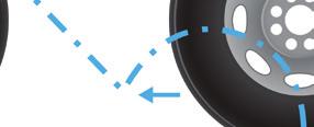
6 Tandem Axle Angles Tandem Scrub Angle Tandem scrub angle is the angle formed by the two thrust lines of a tandem axle vehicle. In the diagram below, misalignment causes the tandem axles to steer the rear of the truck. In this example, the rear of the truck is being steered to the left. Geometric centerline is used as a reference from which to compute individual toe for the rear reference axle. Thrust line is the bisector of the total toe angle of an axle. It represents the direction the axle points compared to the centerline of the vehicle. The steer axle must be turned to offset the push of the axles and keep the vehicle moving straight ahead. This causes every tire on the vehicle to scrub. Tire Wear from Tandem Scrub occurs at the leading edge of the steer tires, in a pattern called inside/outside wear. For example, on the front axle of this vehicle, wear would occur on the outside of the left steer tire and on the inside of the right steer tire. Tire wear would occur on all drive axle tires. Steering Angle Thrust angle is the angle formed by the geometric centerline and the thrust line of an axle Tandem Scrub Angle 6


7 Trailer Alignment and Tire Wear The same conditions that cause tandem scrub on tractors also apply to tractor-trailer combinations. Alignment Angles Affect Rolling Resistance and Fuel Consumption While the effects of misalignment show clearly in tire wear, the effects on fuel consumption are less easy to quantify. Fuel consumption is affected by many factors. However, it is obvious that misalignment must increase rolling resistance and rolling resistance is a major cause of fuel consumption Geometric Centerline Alignment Misaligned trailer axles cause tandem scrub, resulting in rapid wear on all tires. If the trailer doesn t track correctly, it may cause handling problems, use excessive lane space and affect fuel economy. Geometric Centerline Alignment can be used as a reference from which to compute individual toe angles. The Geometric Centerline of a vehicle is established by placing a line from the midpoint of the front axle and the midpoint of the rear-most axle. The Geometric Centerline is not based on frame rails or cross member reference points. The alignment system will establish the Geometric Centerline. Education Guide: Wheel Alignment on Heavy Duty Trucks Alignment Angles and Effects 7


8 Frame Centerline Alignment Frame offset angle is the angle of the frame referenced centerline to the geometric (sensor) centerline. This angle is calculated by the aligner when frame offset measurements are entered into the aligner. Frame offset measurements may be selected and measured by selecting"make Additional Measurements". Separation Separation is the distance between the reference axle adjustment points. This distance may be measured and entered into the aligner before adjusting thrust angle to allow the aligner to calculate how much the axle must be moved at the adjustment point. 8


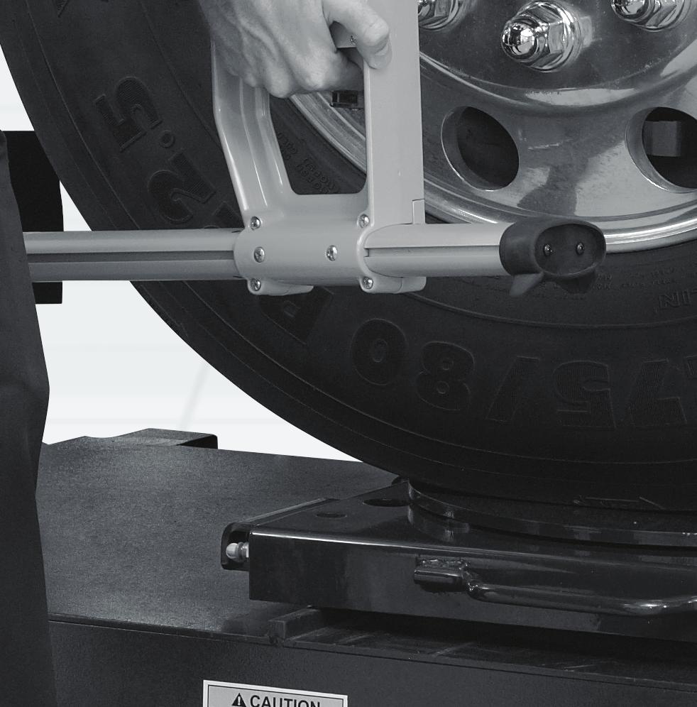
9 Total Alignment In the total alignment procedure, every axle on the vehicle is measured and the axles are set parallel so all the wheels roll in the same direction, minimizing rolling resistance. 3. The next drive axle is then aligned to the reference drive axle. The goal is to reduce tandem scrub angle to 0.00 ± Electronic sensors are mounted on the steer axle and on the tandem drive axles (the reference axle). The sensors are compensated for runout by rolling the vehicle forward approximately 22 inches. 4. The steer axle is aligned to the rear reference axle. 2. The rear reference axle is adjusted to correct thrust angle. The goal is to reduce thrust angle to 0.00 ± For other vehicle confi gurations, similar procedures are followed, aligning all axles to a reference axle. 37 pre-programmed procedures are built in to this system s software. Education Guide: Wheel Alignment on Heavy Duty Trucks Alignment Angles and Effects 9


10 6 Sensor Alignment vs. 4 Sensor Alignment 6 Sensors - Time: Approx. 3 minutes 1 Mount Sensors Roll Compensation 2 3 Measure Caster Turnplate Truck Pusher 4 Diagnose tire wear and handling problems. Start adjustments if needed. 4 Sensors - Time: Approx. 12 minutes 1 Mount Sensors Jacking Comp. 2 3 Measure Caster Front axle Rear axle Turnplate 4 Move front sensors to middle drive axle Jacking Comp. 5 6 Diagnose tire wear and handling problems. Restart entire process if adjustments if needed. Middle axle Front axle Middle axle 10

11 Advantages of Computerized Alignment WinAlign HD Software Education Guide: Wheel Alignment on Heavy Duty Trucks Advantages of Computerized Alignment 11


12 HD Procedure Database WinAlign HD software supports more than 60 customized truck, trailer and bus alignment procedures as well as passenger car and light truck alignment. 37 pre-programmed procedures Specifi cation Database A customized HD specification database supports most vehicle manufacturers by simply scrolling to the specifi c model being aligned. 12


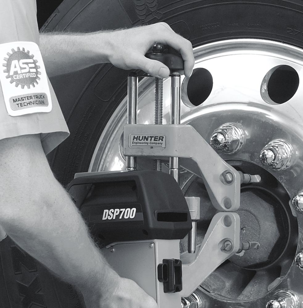
13 Vehicle Specifi cations The Vehicle Specifi cations primary screen displays the alignment specifi cations for the vehicle chosen. The technician may be asked to enter a reference diameter. He can measure the front tire diameter and enter that value in Reference Diameter. When activated, ExpressAlign tool bar (visible in top, right hand corner of aligner screen) automatically shows the customized alignment path for the vehicle selected. ExpressAlign allows movement in procedure by using the mouse and selecting the respective icon relative to sensor location. Compensation Control Screen Hunter's premium six sensor alignment system measures 3 axles at one time. Education Guide: Wheel Alignment on Heavy Duty Trucks Alignment Angles and Effects 13


14 Roll Compensation Roll the vehicle forward and the sensors are compensated. Precise Measurement Display Measuring all three axles at one time offers the advantage quickly diagnosing tire wear related to tandem scrub and excessive total toe. Measurements are compared with the manufacturer's specification and results are shown on the vehicle measurement display screen. Easy-to-read color coding identifi es in- and out- of-specifi cation measurements. 14


15 Automatic calculation WinAlignHD automatically calculates the correction required. As the adjustment is made, the arrow moves across the bar graph target guiding the technician. When the adjustment comes within specifi cation the bar graph changes from red to green. Education Guide: Wheel Alignment on Heavy Duty Trucks Alignment Angles and Effects 15

16 Frame Offset WinAlignHD allows frame offset measurements to be input and displays frame offset angle, recalculating thrust angle from the geometric centerline of the frame. Print Any Screen WinAlignHD allows the user to print any screen for records or to show the vehicle owner the need for service. Before and after alignment measurement screens can be printed to show any out-of-spec condition. Screens can be printed anytime as a guide for the technician. 16


 of a tire and")


17 Recognizing Factors That Can Fool the Alignment Technician A computerized alignment system should have the capacity to recognize several factors that can affect alignment. Wheel Balance and Its Effect on Tire Wear & Vibration When aligning the wheels don t forget about the importance of proper balance. Maximizing tire wear requires proper balance in addition to alignment. Compensation for Runout Runout, due to bent or distorted rims, is common on heavy duty trucks and trailers. The aligner electronically compensates each sensor and correctly measures where the axle points. Identifi es and Corrects for Offset When the wheel is put in motion, centrifugal force acts on the heavy spot, causing the rotating assembly to pull away from its axis. The resulting force causes the wheel to hop. This causes vibration and increased tread wear in the form of cupping. Road Force Hunter s ForceMatch HD balancer quickly measures runout (eccentricity) of a tire and wheel assembly. The roller measures the entire contact patch of the tire, detecting if the assembly is out of round. Match-mounting the high spot on a tire to the low spot on a rim makes the assembly roll as smoothly as possible. Axle offset on heavy duty trucks and trailers is due (for example) to mismatched rims. The aligner allows the technician to measure the distances and input those measurements, which automatically corrects for offset. ForceMatch Roller locates HIGH SPOT on tire Dataset Arms locate LOW SPOT on Rim RUNOUT minimized Education Guide: Wheel Alignment on Heavy Duty Trucks Alignment Angles and Effects 17


18 18


19 Irregular Tire Wear Guide (Steer Tires) Description Appearance Possible Cause Solution Full shoulder Excessive wear extended across the entire shoulder rib to a major tread groove. Excessive camber angle is the primary cause. Measure and align all wheels. If wear is severe, rotate tires. Sawtoothed / Feathered Tread ribs worn so that one side is higher, resulting in step-offs across the tread. Scrubbing due to incorrect toe angles, front and/or rear defective suspension or steering components. Replace worn parts, align vehicle, and if wear patterns are severe, rotate tires. Over Inflation Excessive wear in the center of the tread when properly inflated, appears to cup when viewed across the tread face. Over-inflation expands the tire forcing more wear in the center of the tread. Keep tires properly inflated. Under Inflation Tread is worn unevenly toward the edges of the tire - when properly inflated the tire appears round when viewed across the tread face. Under-inflation causes the tire to collapse, forcing more wear on the edges of the tread. Keep tires properly inflated. Cupping / Dished out areas Localized patches of fast wear creating a scalloped appearance. A result of moderate to sever assembly out of balance condition. Diagnose imbalance condition. Tires should be rotated to drive axle. Diagonal Localized flat spots across the tread often repeating around the tread circumference. Runout and/or out of balance in conjunction with a slow rate of wear. Can also be caused by a loose wheel bearing. Mount as outside drive dual with change in rotation of tire. Education Guide: Wheel Alignment on Heavy Duty Trucks Alignment Angles and Effects 19


.")


20 Diagnostic from the Printout Measuring a multi-axle truck using six sensors in less than 4 minutes offers amazing possibilities for diagnosing premature tire wear and vehicle handling conditions. Cross camber may cause pull to left Negative camber may cause tire wear Incorrect front total toe may cause premature tire wear and/or reduction in directional stability As the thrust angle arrow moves toward center (to the right), the scrub angle arrow will move toward center (to the left). Adjusting thrust angle to zero will result in a zero scrub angle. Thrust angle measurement of 0.00 indicates what the scrub angle will be after the reference axle is adjusted Center axle is pointed to the right of the rear reference axle. This scrub angle will cause a pull to the right. Reference axle Thrust angle indicates axle is pointed left of center 20
21 Troubleshooting Guide Symptom Possible Cause Pull Left/Right Centerline Steering Error Shimmy Vibration Uneven tire pressure / uneven tread wear / mismatched tires Uneven camber Uneven caster Brake drag Suspension/frame sag Unbalanced power assist Bent spindle Worn suspension components (front/rear) Excessive tandem scrub Incorrect front toe Rear wheel misalignment Excessive steering and suspension play Excessive gearbox play Gearbox loose at the frame Excessive positive caster Wheel imbalance Defective suspension and steering components Excessive wheel and tire runout (lateral) Worn tires Under inflation Steering gear loose Excessively loose wheel bearings Ply separation or blister Improperly torqued lug nuts Wheel imbalance Excessive wheel and tire runout (axial) Drum imbalance Drive shaft imbalance Defective u-joints Defective wheel bearings Improper tire inflation Drivetrain misalignment Defective shock or shock mounting Defective tire Education Guide: Wheel Alignment on Heavy Duty Trucks Alignment Angles and Effects 21
22 Troubleshooting Guide (continued) Symptom Noise (abnormal) Hard Steering Loose Steering Excessive Road Shock Braking Instability Possible Cause Defective wheel bearing Overinflation Coarse tread pattern Incorrect alignment (all wheels) Incorrect turning angle Loose or rubbing suspension or steering component Driveline misalignment Low air pressure Steering gear binding Steering lubricant low Excessive positive caster Defective power steering belt Power steering fluid level low Power steering pressure low Steering and suspension component dry or binding Excessively loose wheel bearings Worn steering and suspension components Steering gear assembly loose on mounting Excessive internal wear in steering gear Loose or worn steering shaft coupling Steering gear mis-adjusted Excessive positive caster Low air pressure Worn tires Wrong type tire Wrong shocks Worn shocks Springs worn or sagged Brakes incorrectly adjusted Contaminated brake linings Defective suspension components Incorrect alignment Excessive negative caster Uneven or low tire pressure 22
23 Troubleshooting Guide (continued) Symptom Wander/Instability Squeal/Scuff on Turns Excessive Body Sway Possible Cause Incorrect alignment Worn tires Low air pressure Mismatched tires Worn suspension and steering components Worn or loose steering gear Mis-adjusted steering gear Excessively loose wheel bearings Worn tires Low tire pressure Incorrect turning angle Poor driving habits Worn suspension or steering components Worn shocks or mountings Broken or sagging springs Uneven vehicle load Uneven tire pressure Education Guide: Wheel Alignment on Heavy Duty Trucks Alignment Angles and Effects 23
24 Power Steering Troubleshooting Guide Symptom Insufficient Assist Vehicle Pulls Fluid Leaks Excessive Noise Poor Returnability Possible Cause Low fluid Incorrect fluid Loose/worn belt Defective pump Restricted fluid passages Mechanical bind Inoperative control valve Mis-adjusted control valve Loose hose connection Defective hose Damaged seals Fluid level too high Low fluid level Loose/worn belt Defective pump Restricted fluid passages Defective relief valve Steering column misalignment Yoke plug too tight Valve assembly binding Contaminated fluid Defective u-joints 24
25 Facility Factors How Much Space is Required? Wheel alignment for heavy duty vehicles is not space intensive. The alignment console is usually mounted on a mobile cabinet that can be rolled to the vehicle. Overall dimensions of a console with a 19 monitor and truck & bus sensors mounted are 65 high by 33 deep by 72 wide. Space for the console and the vehicle, and working room for the technician is all that is required. Is a Pit Rack Needed? A pit rack has defi nite advantages in providing room underneath a vehicle for inspection, alignment and suspension repairs. However the only equipment needed for toe, scrub and thrust angle (the most important adjustments to be made) are the alignment system, turning angle gauges (standard equipment with the Hunter system) and a jack for lifting the vehicle during the procedure. Technicians and Training Finding an Alignment Technician Most experienced heavy duty technicians can learn alignment quickly, especially with the help of a computerized system and on-site training. Alignment Training Hunter Engineering Company routinely offers heavy-duty truck alignment courses. These courses provide extensive hands-on experience with equipment and vehicles. On-site training is offered at the time of equipment installation, with retraining available when new technicians are hired. Training in Alignment Merchandising Surprisingly, many experienced people in the trucking industry have only a minimal understanding of wheel alignment and its effects on tire wear, fuel consumption and vehicle handling. Because of this, the technician or service manager may need help in merchandising alignment service. Hands-on training in alignment merchandising should be as much a part of the equipment package as operations training. See your local Hunter representative for details. Pamphlets and brochures can be used at the shop location and in working with fl eet management. Education Guide: Wheel Alignment on Heavy Duty Trucks Alignment Angles and Effects 25


26 Truck/Bus/Trailer Alignment Procedures To properly align heavy-duty trucks, buses and trailers, it is necessary to fi rst determine the axle confi guration. WinAlign 15.0 software offers more than 50 confi gurations of trucks, tractors and trailers. The correct alignment process is automatically loaded based on the chosen confi guration. Hunter s DSP760 sensors offer the advantage of measuring and adjusting a trailer while still attached to the truck / trailer. Twin steer vehicle confi gurations guide the technician through the adjustment process, including establishing parallelism between the steer axles. Truck & Bus Axle Configurations Truck Bus Axle Configurations Trucks Buses 26

27 Trailer Axle Configurations Truck Bus Axle Configurations Semi-Trailers Full Trailers Dollies Cars / Light Truck Education Guide: Wheel Alignment on Heavy Duty Trucks Alignment Angles and Effects 27
28 Glossary A Ackerman Principle: An alignment principle based on vehicle tread width and wheelbase upon which turning angle is computed. Ackerman Arm: A steering component, which provides interconnection between the outer tie rod and spindle. Alignment: The process of measuring and adjusting the position of all wheels attached to a common chassis. Angle: Two intersecting lines that are not parallel. Arc: Any part of a circle or a curved line. Axial Play: Vertical movement of the wheel and tire assembly when inspecting a kingpin. B Balance: This term is used to describe having equal weight distribution about the circumference of a wheel and tire assembly. Bead: A wire steel coil forming an anchor for individual plies and rim attachment of a tire. Bellows: A rubber type seal, which is folded to allow for a telescopic action. Normally referred to as a bellows boot. Bias Belted: A bias ply tire that has reinforcing strips or belts under the tread section. Bias Ply: A tire constructed of alternate plies, which intersect the tire centerline at approximately 35 degrees. Body Roll: The leaning of the vehicle body while cornering. Braking Control: Vehicle stability related to the reaction under all stopping conditions. Bushing: A component made of metal or rubbertype material, used to isolate interconnected moving parts. C Cam Bolt: A bolt and eccentric assembly which, when rotated, will force components to change position. Camber: The inward or outward tilt of the wheel. Camber Roll: A change in camber brought about by suspension changes while cornering. Caster: The forward or rearward tilt of the steering axis. Center Bolt: A bolt that provides centering and attachment of an axle and spring assembly. Centerline Steering: A centered steering wheel while the vehicle is traveling a straight ahead course. Chassis: All major assemblies on a vehicle including suspension, steering, drivetrain, and frame. Everything, except the body. Circumference: The total distance around a circle. Concentric: Two or more components sharing a common center. Conicity: A tire irregularity, which causes the tire to take the shape of a cone when infl ated and loaded. This may generate a lateral force. Contact Area: The total amount of tread surface that contacts the road. Cornering: The ease at which a vehicle travels a curved path. Cross Tube Assembly: Two tie rods and a tube, which transfers the turning effort to the opposite side of the vehicle. Curb Weight: The overall weight of a vehicle, less passengers, luggage, or load. D Degree: A unit of measurement to describe an angle. 28
29 Dial Indicator: An instrument used to measure and display linear displacement. Measurement is displayed on a dial face and the scale is commonly graduated in thousandths. Directional Stability: The tendency for a vehicle to maintain a directed path. Drag Link: A tube or rod used for interconnection between Pitman Arm and tie-rod assemblies. Dynamic Balance: This normally refers to the balance condition of a wheel and tire assembly in motion. F Foot Pound: A unit of measurement used to describe torque force. Frame Angle: The angle formed by a horizontal line and a line drawn parallel to the frame. G Geometric Centerline: A line drawn between the midpoint of the front axle and the midpoint of the rear axle. H Horizontal: Parallel or level with the plane of the horizon. Hub: The assembly that houses the bearings about which the wheel and tire assembly rotates. Hydraulic Pump: A power driven device generating constant volume and pressure. I Included Angle: The sum of the angles, camber and SAI. Independent Suspension: A suspension system that provides an isolated mounting for each wheel to the chassis. Individual Toe: The angle formed by a horizontal line drawn through the plane of one wheel versus a centerline. Intersect: The crossing point of two lines. Jounce Travel: A suspension moving up through its travel. K Kinetic Balance: The balance condition of a rotating wheel related to force generated in a vertical plane. King Pin: A pin used to attach a spindle to an axle. L Lateral Run-out: Side-to-side movement with a rotating wheel or tire. Lead: A slight tendency for a vehicle to move away from its directed course. Linkage: A series of rods or levers used to transmit motion or force. Load Range: A system used to describe the service or weight limitations of a tire. M Memory Steer: A condition where the wheels, rather than returning to straight ahead, tend to remember and seek a previous position. Millimeter: A unit of linear measurement. One millimeter is equivalent to inches. Minute: A unit of measurement used to describe an angle. One minute is equivalent to 1/60 of one degree. O Offset: The lateral displacement of a wheel or axle in respect to a centerline. Oscillate: A back and forth motion at a specifi c frequency. Education Guide: Wheel Alignment on Heavy Duty Trucks Alignment Angles and Effects 29
30 Out-of-Round: A wheel and tire irregularity in which one or both are not concentric with its axis of rotation. Overinflation: Infl ation pressure beyond that which is recommended. Oversteer: A characteristic in which a vehicle has a tendency to turn sharper than the driver intends. P Parallelogram Steering Linkage: A steering linkage design where if all pivot points were connected by lines, these lines would be parallel. Perpendicular: Being at right angles. Pitman Arm: A steering component that provides interconnection between the steering gear sector shaft and the steering linkage. Ply Rating: A method of rating tire strength. Not necessarily indicative of the actual number of plies used. Power Steering: A steering system that incorporates hydraulics to assist in the steering of the wheels. Pre-load: A predetermined amount of load or force applied during assembly to prevent unwanted play during actual operation. Pull: The tendency for a vehicle to steer away from its directed course. R Radial Play: Any lateral movement of the wheel and tire assembly when inspecting a ball-joint or kingpin. Radial Ply Tire: A tire construction type with alternating plies 90 degrees to the tire bead. Radius: The distance from the center to the outer edge of a circle. Rear Axle Departure Offset: The amount in inches from the midpoint of the steer axle (or kingpin on a trailer), where the projected thrustline intersects. Rebound: A suspension moving down through its travel. Recirculating Ball Steering Gear: A steering gear design that is made up of a worm shaft, ball nut, and two recirculating ball circuits. Returnability: The tendency of the front wheels to return to a straight ahead position. Road Crown: The slope of a road from its center. Road Feel: Necessary feedback transmitted from the road surface up to the steering wheel. Road Isolation: The ability of a vehicle to better separate road irregularities from the driver and passengers. Road Shock: An excessive amount of force transmitted from the road surface up to the steering wheel. S Scrub Radius: The radius formed at the road surface between the wheel centerline and steering axis. Semi-Integral Power Assist: A power assist system using a hydraulic pump and a power cylinder in conjunction with the steering gear. Setback: The angle formed between a centerline and a line perpendicular to the front axle. Shim: Thin material of fi ber or metallic makeup used to take up clearance between two parts. Shimmy: A violent shake or oscillation of the front wheels transmitted up to the steering wheel. Shock Absorber: A suspension component used to dampen spring oscillation. Solid Axle Suspension: A suspension system consisting of one steel or aluminum I-beam extended the width of the vehicle. Short Long Arm (SLA): An independent suspension design incorporating unequal length control arms. 30
31 Spindle: A component on which a wheel and tire assembly rotates. Stability: The tendency of a vehicle to maintain a directed course. Stabilizer: A steel bar used to minimize body roll. Steering Axis Inclination: The angle formed by an imaginary line drawn through the steering axis versus vertical. Steering Gear: A mechanical device used to convert the rotary motion at the steering wheel to a lateral motion. Steering Shaft: A tube or rod, which interconnects the steering wheel to a lateral motion. Strut: Any support used between two parts. Suspension: An assembly used to support weight, absorb and dampen shock, help maintain tire contact and proper wheel to chassis relationship. Suspension Height: The specifi ed distance between one or more points on a vehicle to the road surface. T Tandem Lateral Offset: When the geometric centerline does not cross the midpoint of all axles. Tandem Scrub Angle: The angle formed by the intersection of horizontal lines drawn through each rear axle when total toe and the offset is zero. Thrust Angle: The angle formed by thrustline and geometric centerline. Thrustline: A bisector of rear total toe. Tie Rod Assembly: The outer most assemblies on a parallelogram steering linkage. These assemblies are attached to the drag link and Ackerman Arms. Tie Rod End: The ball and socket assembly of a tie rod. Tie Rod Sleeve: A threaded tube that provides connection and adjustment of a tie rod assembly. Tire Force Variation: A tire irregularity, in which there is a difference in radial stiffness about the circumference of the tire. Toe: The comparison of a horizontal line drawn through both wheels of the same axle. Turning Angle: The difference in the turning angle of the front wheels in a turn. Torsion Bar: A spring steel bar used in place of a coil spring. Tracking: The interrelated paths taken by the front and rear wheels. Treadwidth: The dimension as measured between the centerlines of the wheels on the same axle. Treadwear Indicators: Ridges molded between the ribs of the tread that visibly indicate a worn tire. U Under Inflation: Air pressure below that which is specifi ed. Understeer: A characteristic in which a vehicle has a tendency to turn less than the driver intends. V Vertical: Being exactly upright or plumb. Vibration: To constantly oscillate at a specifi c frequency. W Waddle: The lateral movement of a vehicle, usually caused by some type of tire or wheel imperfection. Wander: The tendency of a vehicle to drift to either side of its directed course. Wheelbase: The dimension as measured between the center of the front and rear axles. Education Guide: Wheel Alignment on Heavy Duty Trucks Alignment Angles and Effects 31
32 0117EH Copyright 2017, Hunter Engineering Company Form 995-T-2, 01/17 Supersedes form 995-T-2, 09/06
2004 SUSPENSION. Wheel Alignment - Corvette. Caster Cross +/ / Fastener Tightening Specifications Specification Application
 2004 SUSPENSION Wheel Alignment - Corvette SPECIFICATIONS WHEEL ALIGNMENT SPECIFICATIONS Wheel Alignment Specifications Camber Cross Caster Cross Suspension Camber Tolerance Caster Tolerance FE1 & FE3
Camber Angle. Wheel Alignment. Camber Split. Caster Angle. Caster and Ride Height. Toe Angle. AUMT Wheel Alignment
 AUMT 1316 - Wheel Alignment 11/15/11 Camber Angle Wheel Alignment Donald Jones Brookhaven College Camber Split Camber is the amount that the centerline of the wheel tilts away from true vertical when viewed
Basic Wheel Alignment Techniques
 Basic Wheel Alignment Techniques MASTERING THE BASICS: Modern steering and suspension systems are great examples of solid geometry at work. Wheel alignment integrates all the factors of steering and suspension
Wheel Alignment Fundamentals
 CHAPTER 67 Wheel Alignment Fundamentals OBJECTIVES Upon completion of this chapter, you should be able to: Describe each wheel alignment angle. Tell which alignment angles cause wear or pull. KEY TERMS
BASIC WHEEL ALIGNMENT
 BASIC WHEEL ALIGNMENT You have got to know all the angles. Correct wheel alignment plays a huge part in a customer s positive driving experience. Having it dialed in correctly is essential to proper vehicle
ATASA 5 th. Wheel Alignment. Please Read The Summary. ATASA 5 TH Study Guide Chapter 47 Pages: Wheel Alignment 64 Points
 ATASA 5 TH Study Guide Chapter 47 Pages: 1403 1423 64 Points Please Read The Summary Before We Begin Keeping in mind the Career Cluster of Transportation, Distribution & Logistics Ask yourself: What careers
SUSPENSION 2-1 SUSPENSION TABLE OF CONTENTS
 XJ SUSPENSION 2-1 SUSPENSION TABLE OF CONTENTS page ALIGNMENT... 1 FRONT SUSPENSION... 7 page REAR SUSPENSION... 16 ALIGNMENT TABLE OF CONTENTS page AND WHEEL ALIGNMENT...1 DIAGNOSIS AND TESTING SUSPENSION
Why do cars need Alignment
 Why do cars need Alignment The main purpose of wheel alignment is to make the tires roll without Scuffing, slipping, or dragging under all operating conditions. Caster Camber Toe Steering axis inclination
TRUCK AND BUS TYRE I TECHNICAL MANUAL MAINTENANCE AND CARE
 TRUCK AND BUS TYRE I TECHNICAL MANUAL MAINTENANCE AND CARE About tyre inflation Truck alignment and tyre wear Tyre damage TECHNICAL INFORMATION MAINTENANCE AND CARE About tyre inflation ONE OF THE MOST
GENERAL INFORMATION. Wheel Alignment Theory & Operation
 Fig. 1: Checking Steering Linkage GENERAL INFORMATION Wheel Alignment Theory & Operation ADJUSTMENTS NOTE: This article is intended for general information purposes only. This information may not apply
1. SPECIFICATIONS 2. WHEEL ALIGNMENT Front Suspension. (gas type) Rear Suspension. (gas type)
 Rear Suspension. (gas type)") 441101 053 1. SPECIFICATIONS Front Suspension Rear Suspension Description Suspension type Spring type Shock absorber type Stabilizer bar type Suspension type Spring type Shock absorber type Stabilizer
441101 053 1. SPECIFICATIONS Front Suspension Rear Suspension Description Suspension type Spring type Shock absorber type Stabilizer bar type Suspension type Spring type Shock absorber type Stabilizer
SUSPENSION 2-1 SUSPENSION CONTENTS
 TJ SUSPENSION 2-1 SUSPENSION CONTENTS page ALIGNMENT... 1 FRONT SUSPENSION... 5 page REAR SUSPENSION... 12 ALIGNMENT INDEX page GENERAL INFORMATION WHEEL ALIGNMENT... 1 DIAGNOSIS AND TESTING SUSPENSION
SUSPENSION 2-1 SUSPENSION CONTENTS
 TJ SUSPENSION 2-1 SUSPENSION CONTENTS page ALIGNMENT... 1 FRONT SUSPENSION... 6 page REAR SUSPENSION... 13 ALIGNMENT INDEX page DESCRIPTION AND OPERATION WHEEL ALIGNMENT... 1 DIAGNOSIS AND TESTING SUSPENSION
Wheel Alignment Defined
 Wheel Alignment Defined While it's often referred to simply as an "alignment" or "wheel alignment," it's really complex suspension angles that are being measured and a variety of suspension components
SUSPENSION 2-1 SUSPENSION CONTENTS
 WJ SUSPENSION 2-1 SUSPENSION CONTENTS page ALIGNMENT... 1 FRONT SUSPENSION... 4 page REAR SUSPENSION... 15 ALIGNMENT INDEX page AND WHEEL ALIGNMENT... 1 SERVICE PROCEDURES PRE-ALIGNMENT... 2 AND WHEEL
1. SPECIFICATIONS 2. WHEEL ALIGNMENT
 441101 083 1. SPECIFICATIONS Front Suspension Rear Suspension Description Suspension type Spring type Shock absorber type Stabilizer bar type Suspension type Spring type Shock absorber type Stabilizer
SUSPENSION 2-1 SUSPENSION CONTENTS
 ZJ SUSPENSION 2-1 SUSPENSION CONTENTS page ALIGNMENT... 1 FRONT SUSPENSION... 6 page REAR SUSPENSION... 14 ALIGNMENT INDEX page GENERAL INFORMATION WHEEL ALIGNMENT... 1 DIAGNOSIS AND TESTING SUSPENSION
Steering and Suspension
 The Steering and Suspension system is engineered to allow the vehicle to turn and absorb road irregularities. The suspension is comprised of springs, suspension arms or links and shock dampers. These components
SECTION Wheels and Tires
 204-04-i Wheels and Tires 204-04-i SECTION 204-04 Wheels and Tires CONTENTS PAGE DIAGNOSIS AND TESTING Wheels And Tires... 204-04-2 Inspection and Verification... 204-04-2 Tire Wear... 204-04-3 Symptom
DIAGNOSIS AND TESTING
 DIAGNOSIS AND TESTING SUSPENSION AND STEERING SYSTEM 2007 SUSPENSION Suspension - Nitro CONDITION POSSIBLE CAUSES CORRECTION FRONT END NOISE 1. Loose or worn wheel bearings. 1. Replace wheel bearings.
SUSPENSION 2-1 SUSPENSION TABLE OF CONTENTS
 DN SUSPENSION 2-1 SUSPENSION TABLE OF CONTENTS page ALIGNMENT... 1 FRONT SUSPENSION - 4x2... 6 page FRONT SUSPENSION - 4x4... 14 REAR SUSPENSION... 23 ALIGNMENT TABLE OF CONTENTS page AND OPERATION WHEEL
Tire 16 inch 225/75R inch 255/60R 18
 417009 143 1. SPECIFICATIONS Description Specification Tire 16 inch 225/75R 16 Tire inflation pressure 18 inch 255/60R 18 Front: 32 psi Rear: 32 psi (44 psi: when the vehicle is fully laden with luggage)
The WHAT and WHY of. Toe Caster - Camber Kingpin Inclination - Thrust Angle Steering Angle Wheel setback
 The WHAT and WHY of Toe Caster - Camber Kingpin Inclination - Thrust Angle Steering Angle Wheel setback WHEEL ALIGNMENT SIMPLIFIED Wheel alignment is often considered complicated and hard to understand
FRONT SUSPENSION AND STEERING LINKAGE
 A FRONT SUSPENSION AND STEERING LINKAGE CONTENTS GROUP 2 Page LOWER BALL JOINTS 12 LOWER CONTROL ARM AND SHAFT... 9 LOWER CONTROL ARM STRUT 12 PRE-ALIGNMENT INSPECTION Height Adjustment., 4 RUBBER ISOLATED
AER Automotive Steering and Suspension
 2013 NATEF JOB TASKS COMPLETION REQUIREMENT: P1-95% P2-80% P3-50% Student Name: DETAILED COURSE CONTENT AUTOMOTIVE SUSPENSION AND STEERING TECHNICIAN DEMONSTRATE PROFICIENCY IN SUSPENSION AND STEERING
Customer Engagement - Execution Playbook Module 1 WHEEL ALIGNMENTS ALIGNMENTS
 Customer Engagement - Execution Playbook Module 1 WHEEL ALIGNMENTS -------------------------- ALIGNMENTS 101 ------------------------------ While a wheel alignment is often referred to simply as an alignment,
FRONT SUSPENSION GROUP 2 FRONT SUSPENSION 2-1 CONTENTS SPECIFICATIONS VC-1, VC-2, VC-3 VY-1 TOOL LIST. Page
 GROUP 2 FRONT SUSPENSION CONTENTS Page Specifications 1 Tool List.... 1 Torque Reference 2 Preparation for Measuring Front End Alignment... 2 Front Suspension Height Adjustment 3 Front Suspension Alignment
SECTION steering mechanism
 07-302.01/ 1 2011MR17 SECTION 07-302.01 GENERAL Description See Figure 1. The includes the steering wheel (1), the steering column, the miter box (3), the steering shafts (2 and 4), and the drag link (7).
UNIBODY/FRAME/WHEEL ALIGNMENT II ABCT 2212
 UNIBODY/FRAME/WHEEL ALIGNMENT II ABCT 2212 A. Course Description Credits: 6.00 Lecture Hours/Week: 1.00 Lab Hours/Week: 5.00 OJT Hours/Week: 0 Prerequisites: None Corequisites: None MnTC Goals: None This
Fundamentals of Steering Systems ME5670
 Fundamentals of Steering Systems ME5670 Class timing Monday: 14:30 Hrs 16:00 Hrs Thursday: 16:30 Hrs 17:30 Hrs Lecture 3 Thomas Gillespie, Fundamentals of Vehicle Dynamics, SAE, 1992. http://www.me.utexas.edu/~longoria/vsdc/clog.html
STEERING SYSTEM Introduction
 STEERING SYSTEM Introduction The steering makes it possible to change direction. The steering must be reliable and safe; there must not be too much play in the steering. It must be possible to steer accurately.
AXLE ALIGNMENT ZF (40 FT)
") SECTION 04-000.10 04-000.10/ 1 2010DE06 GENERAL CONDITIONS See Figures 1 and 2 for the geometry of the frontand rear axles. Figure 3 represents the axis system of a Nova LFS 40-ft bus. Before performing
SECTION 04-000.10 04-000.10/ 1 2010DE06 GENERAL CONDITIONS See Figures 1 and 2 for the geometry of the frontand rear axles. Figure 3 represents the axis system of a Nova LFS 40-ft bus. Before performing
2011 MKS Workshop Manual. SECTION : Suspension System - General Information DESCRIPTION AND OPERATION Procedure revision date: 05/25/2010
 SECTION 204-00: Suspension System - General Information 2011 MKS Workshop Manual DESCRIPTION AND OPERATION Procedure revision date: 05/25/2010 Wheel Alignment Angles Camber Negative and Positive Camber
 Page 1 of 8 SECTION 204-00: Suspension System - General Information 1998 Contour/Mystique Workshop Manual DIAGNOSIS AND TESTING Procedure revision date: 09/14/2001 Suspension System Special Tool(s) Dial
SUSPENSION 2-1 SUSPENSION CONTENTS
 DN SUSPENSION 2-1 SUSPENSION CONTENTS page ALIGNMENT... 1 FRONT SUSPENSION... 5 page REAR SUSPENSION... 13 ALIGNMENT INDEX page GENERAL INFORMATION WHEEL ALIGNMENT... 1 DIAGNOSIS AND TESTING PRE-ALIGNMENT
Suspension and Steering Alignment
 Suspension and Steering Alignment Matthew Whitten Brookhaven College Alignment Components Ride height Caster Camber Included angle Scrub radius Thrust angle Toe Turning radius Toe out on turns Steering
2013 NATEF Task Area A-4 Suspension, Steering, Alignment7-2013
 2013 NATEF Task Area A-4 Suspension, Steering, Alignment7-2013 A. Steering System Diagnosis & Repair B. Suspension System Diagnosis & Repair C. Wheel Alignment Diagnosis & Adjustment D. Wheel & Tire Diagnosis
TRADE OF HEAVY VEHICLE MECHANIC
 TRADE OF HEAVY VEHICLE MECHANIC PHASE 2 Module 8 Steering and Suspension Systems UNIT: 2 Table of Contents 1.0 Learning Outcome... 1 1.1 Key Learning Points... 1 2.0 Health and Safety... 3 3.0 The Function
WinAlign. Alignment Systems Fast and accurate wheel alignment for multi-axle trucks NEW!
 WinAlign HD Alignment Systems Fast and accurate wheel alignment for multi-axle trucks NEW! New DSP760T alignment sensors Hunter's new DSP760T heavy-duty alignment sensors reduce setup time and provide
Hemet High School NATEF SUSPENSION AND STEERING CHECKLIST. Name Date Period
 Hemet High School NATEF SUSPENSION AND STEERING CHECKLIST Name Period For every task in Suspension and Steering, the following safety requirement must be strictly enforced: Comply with personal and environmental
1. General Description
 General Description 1. General Description A: SPECIFICATION Front Rear Model Wheel arch height (Tolerance: +12 mm 24 mm ( +0.47 in 0.94 in)) mm (in) 376 (14.8) Camber (Tolerance: 0 45 Differences between
Sequoia power steering rack service Match-mounting wheels and tires Oxygen sensor circuit diagnosis
 In this issue: Sequoia power steering rack service Match-mounting wheels and tires Oxygen sensor circuit diagnosis PHASE MATCHING Often referred to as match mounting, phase matching involves mounting the
Typical mounting of a dial indicator for a radial check. Moog Automotive, Inc.
 Inspect / Service / Test / Replace To find out if the ball joint is loose beyond manufacturer's specifications, use an accurate measuring device. Most load carrying ball joints have a wear limit of 0.060"
VERNON COLLEGE SYLLABUS. DIVISION: Information & Industrial Technology DATE: Fall COURSE NUMBER AND TITLE: AUMT 1416 Suspension and Steering
 VERNON COLLEGE SYLLABUS DIVISION: Information & Industrial Technology DATE: Fall 2010 CREDIT HRS: 4 HRS/WK LEC: 3 HRS/WK LAB: 3 LEC/LAB: 6 I. CATALOG DESCRIPTION: Theory and operation of automotive suspension
Unit No.03 Front axle, Steering system, Rear axle, Wheel & Tyres
 Unit No.03 Front axle, Steering system, Rear axle, Wheel & Tyres Prepared by, Prof. Santosh Kailas Chandole ME (Design Engineering) BE (Automobile Engineering) Steering system STEERING REQUIREMNTS: It
WinAlign. Alignment Systems Fast and accurate wheel alignment for multi-axle trucks NEW!
 WinAlign HD Alignment Systems Fast and accurate wheel alignment for multi-axle trucks NEW! New DSP760T alignment sensors Hunter's new DSP760T heavy-duty alignment sensors reduce setup time and provide
Hunter Alignment. The following courses are available. Read descriptions of each on the pages that follow.
 Hunter Alignment Two to five day courses for both entry-level and seasoned technicians who need wheel alignment training. Hunter Alignment courses are presented across the country. The following courses
WHEELS BEARINGS TIRES
 GROUP 22 WHEELS BEARINGS TIRES CONTENTS Page GENERAL INFORMATION 1 SERVICE DIAGNOSIS 1 SERVICE PROCEDURES... 2 WHEELS... 2 Page BEARINGS 2 TIRES 4 SPECIFICATIONS AND TIGHTENING REFERENCE.. In Rear of Manual
Wheel Alignment And Diagnostic Angles (STE04)
") Module 1 Wheel Alignments Wheel Alignment And Diagnostic Angles (STE04) Wheel Alignments o Conditions Requiring An Alignment o Conditions Requiring An Alignment (cont d) o Why We Do Checks And Alignments
Module 1 Wheel Alignments Wheel Alignment And Diagnostic Angles (STE04) Wheel Alignments o Conditions Requiring An Alignment o Conditions Requiring An Alignment (cont d) o Why We Do Checks And Alignments
Hunter Alignment. This alignment education series also helps prepare technicians for the ASE A4 Certification.
 Hunter Alignment Hunter offers entry and intermediate level alignment courses throughout the county. The combination of discussion and hands-on lab/shop activities melds theory with reality. This alignment
TIRES AND WHEELS 22-1 TIRES AND WHEELS CONTENTS
 ZG TIRES AND WHEELS 22-1 TIRES AND WHEELS CONTENTS TIRES... 1 WHEELS... 7 TIRES INDEX DESCRIPTION AND OPERATION RADIAL-PLY TIRES... 2 REPLACEMENT TIRES... 3 SPARE TIRE (TEMPORARY)... 2 TIRE INFLATION PRESSURES...
Fiat - Argentina - Wheel Aligner / Headlamp Aimer #16435
 2017 Fiat - Argentina - Wheel Aligner / Headlamp Aimer #16435 Wheel Aligner / Headlamp Aimer Operation & Maintenance Manual Overview Fori Automation Version 1.2 4/21/2017 TABLE OF CONTENTS Section 1.0
TIRE BASICS GENERAL INFORMATION WHAT S INSIDE A TIRE TREAD BELTS BELT EDGE INSULATION BODY PLIES INNERLINER CASING BEAD SIDEWALL BEAD FILLER
 WHAT S INSIDE A TIRE BELTS TREAD BELT EDGE INSULATION BODY PLIES INNERLINER CASING BEAD SIDEWALL The tire s INNERLINER -- keeps air inside the tire. BEAD FILLER The CASING (or CARCASS) the internal substructure
SR01 Steering, Gearbox
 Uniform Procedures For Collision Repair SR01 Steering, Gearbox 1. Description This procedure describes the diagnosis, repair, and inspection of a gearbox-type steering system. Requirements for both manual
FRONT & REAR SUSPENSION SECTIONSU CONTENTS IDX. FRONT SUSPENSION...2 Precautions...2. REAR SUSPENSION...14 Precautions...14
 FRONT & REAR SUSPENSION SECTIONSU GI MA EM LC EC CONTENTS FE FRONT SUSPENSION...2 Precautions...2 PRECAUTIONS...2 Preparation...2 SPECIAL SERVICE TOOLS...2 COMMERCIAL SERVICE TOOLS...2 Noise, Vibration
TIRES AND WHEELS 22-1 TIRES AND WHEELS CONTENTS
 ZJ TIRES AND WHEELS 22-1 TIRES AND WHEELS CONTENTS TIRES... 1 WHEELS... 7 TIRES INDEX DESCRIPTION AND OPERATION RADIAL-PLY TIRES... 2 REPLACEMENT TIRES... 3 SPARE TIRE TEMPORARY... 2 TIRE INFLATION PRESSURES...
Automotive Suspension and Steering Course number-20123
 Automotive Suspension and Steering Course number-20123 There is a high demand for trained individuals in the automotive service field. The desire for the students to receive industry-based training at
1940 Hudson SERVICING THE FRONT SUSPENSION SYSTEM
 1940 Hudson SERVICING THE FRONT SUSPENSION SYSTEM Source of this material is from 1940 Series, Issue 3, November-December Hudson Service Magazine SERVICING THE FRONT SUSPENSION SYSTEM No set rule can be
WinAlign HD Alignment Systems Fast and accurate wheel alignment for multi-axle trucks NEW
 WinAlign HD Alignment Systems Fast and accurate wheel alignment for multi-axle trucks NEW New DSP760T alignment sensors Hunter's new DSP760T heavy-duty alignment sensors reduce setup time and provide accurate
FRONT & REAR SUSPENSION SECTIONSU CONTENTS IDX. FRONT SUSPENSION...2 Precautions...2. Service Data and Specifications (SDS)...21
...21") FRONT & REAR SUSPENSION SECTIONSU GI MA EM LC EC CONTENTS FE...2 Precautions...2 PRECAUTIONS...2 Preparation...2 SPECIAL SERVICE TOOLS...2 COMMERCIAL SERVICE TOOLS...2 Noise, Vibration and Harshness (NVH)
FRONT & REAR SUSPENSION SECTIONSU GI MA EM LC EC CONTENTS FE...2 Precautions...2 PRECAUTIONS...2 Preparation...2 SPECIAL SERVICE TOOLS...2 COMMERCIAL SERVICE TOOLS...2 Noise, Vibration and Harshness (NVH)
Modern Auto Tech Study Guide Chapter 65 & 66 Pages Tires, Wheels, Bearings 51 Points. Automotive Service. Danger of Old Tires!!
 Modern Auto Tech Study Guide Chapter 65 & 66 Pages 1241 1278 Tires, Wheels, Bearings 51 Points Automotive Service Danger of Old Tires!! Tires Manufactured Since 2000 Since 2000, the week and year the tire
CHAPTER 7 FRONT AXLE
 CHAPTER 7 FRONT AXLE 1. STRUCTURE FRONT AXLE 1.1 FRONT AXLE STRUCTURE 704W701A (1) Front Bracket (2) Rear Bracket (3) Center Pin (4) Front Axle Support (5) Bevel Gear Case (6) Front Axle Case (7) Front
WHEELS AND TIRES 22-1 WHEELS AND TIRES CONTENTS
 J WHEELS AND TIRES 22-1 WHEELS AND TIRES CONTENTS page SPECIFICATIONS... 12 TIRES... 1 page VEHICLE VIBRATION... 10 WHEELS... 6 TIRES INDEX page Cleaning of Tires... 2 General Information... 1 Pressure
ALTERNATE LUG WEAR BOTH SHOULDER WEAR TYRE WEAR CONDITIONS WHAT S HAPPENING WHAT S HAPPENING
 ALTERNATE LUG WEAR The tyre s lugs are not wearing consistently because they are not making uniform contact with the highway. Alternate lug wear may routinely develop on certain tread types. The only solution
FRONT & REAR SUSPENSION SECTIONSU CONTENTS IDX. FRONT SUSPENSION...2 Precautions...2
 FRONT & REAR SUSPENSION SECTIONSU GI MA EM LC CONTENTS EC FE FRONT SUSPENSION...2 Precautions...2 PRECAUTIONS...2 Preparation...2 SPECIAL SERVICE TOOLS...2 COMMERCIAL SERVICE TOOLS...2 Noise, Vibration
Return To Main Table of Contents GENERAL... 2 STRUT ASSEMBLY LOWER ARM STABILIZER BAR CENTER MEMBER WHEEL AND TIRE...
 FRONT SUSPENSION Return To Main Table of Contents GENERAL... 2 STRUT ASSEMBLY... 11 LOWER ARM... 13 STABILIZER BAR... 17 CENTER MEMBER... 19 WHEEL AND TIRE... 21 GENERAL GENERAL SPECIFICATIONS Suspension
FRONT SUSPENSION SECTION CONTENTS E SUSPENSION FSU-1 FSU
 E SUSPENSION A SECTION FRONT SUSPENSION B C D CONTENTS FSU PRECAUTIONS... 2 Precautions... 2 PREPARATION... 3 Special Service Tools... 3 Commercial Service Tools... 3 NOISE VIBRATION AND HARSHNESS (NVH)
Unit 3. The different types of steering gears are as follows:
 Steering Gears One of the important human interface systems in the automobile is the steering gear. The steering gear is a device for converting the rotary motion of the steering wheel into straight line
Independent Front Suspension
 Independent Front Suspension Technical Training Contents Why Independent? Tuthill Models Features and Benefits Description Special Tools Regular Maintenance Troubleshooting Available Kits Contacting Tuthill
Tire 16 inch 225/75R inch 255/60R 18
 417009 133 1. SPECIFICATIONS Description Specification Tire 16 inch 225/75R 16 Tire inflation pressure 18 inch 255/60R 18 Front: 32 psi Rear: 32 psi (44 psi: when the vehicle is fully laden with luggage)
Alternate Lug Wear. Appearance. What's Happening. Probable Causes
 Alternate Lug Wear The tire's lugs are not wearing consistently because they are not making uniform contact with the highway. mismatched duals inconsistent dual inflation (10 PSI or greater) tread design/tire
WinAlign Operation Instructions for VAG Aligner
 OPERATION INSTRUCTIONS Form 6611TE-05, 06-13 Supersedes Form 6611TE-05, 01-13 WinAlign Operation Instructions for VAG Aligner Version 14.0 Copyright 2013 Hunter Engineering Company Contents Contents...
How to Set the Alignment on Ford Mustangs
 How to Set the Alignment on 1967-1973 Ford Mustangs Let's Get This Straight - Mustang Monthly Magazine Christopher Campbell Technical Editor March 25, 2015 Frontend alignment is one of the most basic adjustments
Section I TORSION-AIRE FRONT WHEEL SUSPENSION CONTENTS DATA AND SPECIFICATIONS MANUAL STEERING WITH POWER STEERING SPECIAL TOOLS
 CHRYSLER SERVICE MANUAL FRONT WHEEL SUSPENSION 7 Section I TORSION-AIRE FRONT WHEEL SUSPENSION CONTENTS Page Servicing the Front Wheel Suspension 10 Checking Front Suspension Height.. 12 Front Wheel Alignment
INDEX GENERAL. Page Connecting Rod 2M-3 Front Wheel Alignment 2M-4 Front Wheel Shimmy 2M-5 General 2M-1
 INDEX Page Connecting Rod 2M-3 Front Wheel Alignment 2M-4 Front Wheel Shimmy 2M-5 General 2M-1 Pago Specifications 21-8 Steering Damper 2M-3 Steering Wheel Spoke Alignment 2M-5 Tie Rod 2M-3 GENERAL The
SU11 Independant, SLA
 Uniform Procedures For Collision Repair UPCR SU11 Independant, SLA 1. Description This procedure describes the diagnosis, repair, and inspection of an independent, short-arm, long-arm (SLA) suspension
ALIGNMENT AND ROAD CROWN
 Classification: Reference: Date: ST08-001 NTB08-097 October 9, 2008 ALIGNMENT AND ROAD CROWN APPLIED VEHICLES: All Nissan - except GT-R SERVICE INFORMATION Customers may report that their vehicle pulls
Wheel Alignment - Basics
 Service Training Self Study Program 860103 Wheel Alignment - Basics Volkswagen Group of America, Inc. Volkswagen Academy Printed in U.S.A. Printed 2/2012 Course Number 860103 2012 Volkswagen Group of America,
Adjustable Tie-rod Ends (Mm5TR-1)
") 3430 Sacramento Dr., Unit D San Luis Obispo, CA 93401 Telephone: 805/544-8748 Fax: 805/544-8645 www.maximummotorsports.com 2005-10 Adjustable Tie-rod Ends (Mm5TR-1) 3. Remove the front wheels. 4. Loosen
3430 Sacramento Dr., Unit D San Luis Obispo, CA 93401 Telephone: 805/544-8748 Fax: 805/544-8645 www.maximummotorsports.com 2005-10 Adjustable Tie-rod Ends (Mm5TR-1) 3. Remove the front wheels. 4. Loosen
Diesel Technology: Steering and Suspension
 Diesel Technology: Steering and Suspension National Skills Crosswalk The following NATEF Suspension and Steering tasks (rev. 2004) are covered in this publication. The chart shows where each task is located
SUSPENSION 2-1 SUSPENSION CONTENTS
 PL SUSPENSION 2-1 SUSPENSION CONTENTS page FRONT SUSPENSION... 10 REAR SUSPENSION... 39 page WHEEL ALIGNMENT... 1 WHEEL ALIGNMENT INDEX page DESCRIPTION AND OPERATION COMPETITION PACKAGE ALIGNMENT... 2
Torque steer effects resulting from tyre aligning torque Effect of kinematics and elastokinematics
 P refa c e Tyres of suspension and drive 1.1 General characteristics of wheel suspensions 1.2 Independent wheel suspensions- general 1.2.1 Requirements 1.2.2 Double wishbone suspensions 1.2.3 McPherson
FRONT & REAR SUSPENSION SECTIONSU CONTENTS IDX. FRONT SUSPENSION...2 Precautions...2
 FRONT & REAR SUSPENSION SECTIONSU GI MA EM LC EC CONTENTS FE...2 Precautions...2 PRECAUTIONS...2 Preparation...2 SPECIAL SERVICE TOOLS...2 COMMERCIAL SERVICE TOOLS...2 Noise, Vibration and Harshness (NVH)
INTRO/APPLICATIONS PARTS TOOLS ACCESSORIES BRAKE & CV SPC GEAR & INDEXES APPLICATIONS PARTS
 TABLE OF CONTENTS INTRO/.................. 2-39 How to Use the Sourcebook......................................2 How to Sell Alignment...........................................2 Training Resources..............................................3
Modern Auto Tech Study Guide Chapter 67 & 69 Pages Suspension & Steering 32 Points. Automotive Service
 Modern Auto Tech Study Guide Chapter 67 & 69 Pages 1280 1346 Suspension & Steering 32 Points Automotive Service 1. The system allows a vehicle s tires & wheels to move up and down as they roll. Steering
SU01 Independent, Strut
 Uniform Procedures For Collision Repair SU01 Independent, Strut 1. Description This procedure describes the diagnosis, repair, and inspection of an independent, strut-type suspension system. 2. Purpose
2011+ Adjustable Tie-rod Ends (Mm5TR-2)
") 3430 Sacramento Dr., Unit D San Luis Obispo, CA 93401 Telephone: 805/544-8748 Fax: 805/544-8645 www.maximummotorsports.com 2011+ Adjustable Tie-rod Ends (Mm5TR-2) Instructions 1. Set the parking brake
3430 Sacramento Dr., Unit D San Luis Obispo, CA 93401 Telephone: 805/544-8748 Fax: 805/544-8645 www.maximummotorsports.com 2011+ Adjustable Tie-rod Ends (Mm5TR-2) Instructions 1. Set the parking brake
total vehicle alignment
 2 total vehicle alignment A guide created By: TBS Factoring service TBS Factoring Service 2 total vehicle alignment...created by tbs factoring service TBS Factoring Service, LLC is a leading provider of
Technician Handbook. 453 Suspension, Steering and Handling. Technician Objectives
 Technician Objectives 1. List the six functions of suspension components.. 2. List the six major groups of components that require inspection. 3. Explain the inspection methods for the individual suspension
Wheel Alignment Service
 CHAPTER 68 Wheel Alignment Service OBJECTIVES Upon completion of this chapter, you should be able to: Perform a prealignment inspection of the steering and suspension. Describe how to adjust caster, camber,
TIRES AND WHEELS 22-1 TIRES AND WHEELS CONTENTS
 PL TIRES AND WHEELS 22-1 TIRES AND WHEELS CONTENTS page page TIRES... 1 WHEELS... 8 TIRES INDEX page DESCRIPTION AND OPERATION RADIAL-PLY TIRES... 2 REPLACEMENT TIRES... 3 SPARE TIRE TEMPORARY... 2 TIRE
WHEEL AND TIRE GROUP CONTENTS WHEEL AND TIRE DIAGNOSIS WHEEL AND TIRE SPECIFICATIONS ON-VEHICLE SERVICE...
 31-1 GROUP 31 CONTENTS.... 31-2 DIAGNOSIS........................ 31-2 WHEEL BALANCE ACCURACY........ 31-3 ON-VEHICLE SERVICE........... 31-7 TIRE INFLATION PRESSURE CHECK... 31-7 TIRE WEAR CHECK..................
WHEEL ALIGNMENT SPECIFICATIONS & PROCEDURES
 WHEEL ALIGNMENT SPECIFICATIONS & PROCEDURES 1988 Jeep Cherokee 1988 Wheel Alignment INTRODUCTION PRE-ALIGNMENT VEHICLE CHECKS Prior to making wheel alignment adjustments, check and adjust the following
MM Caster/Camber Plates, (MMCC7989)
") 3430 Sacramento Dr., Unit D San Luis Obispo, CA 93401 Telephone: 805/544-8748 Fax: 805/544-8645 www.maximummotorsports.com MM Caster/Camber Plates, 1979-89 (MMCC7989) IMPORTANT: The bearing used in our
3430 Sacramento Dr., Unit D San Luis Obispo, CA 93401 Telephone: 805/544-8748 Fax: 805/544-8645 www.maximummotorsports.com MM Caster/Camber Plates, 1979-89 (MMCC7989) IMPORTANT: The bearing used in our
SR11 Steering, Rack-And-Pinion
 Uniform Procedures For Collision Repair SR11 Steering, Rack-And-Pinion SR Menu Procedure Menu 1. Description This procedure describes diagnosis, replacement, and inspection of a rack-and-pinion steering
Unit HV04K Knowledge of Heavy Vehicle Chassis Units and Components
 Assessment Requirements Unit HV04K Knowledge of Heavy Vehicle Chassis Units and Components Content: Chassis layouts i. types of chassis ii. axle configurations iii. rear steered axles iv. self-steered
DIAGNOSIS AND TESTING
 211-00-1 Steering System General Information 211-00-1 DIAGNOSIS AND TESTING Steering System Special Tool(s) Dial Thermometer 0-220 F 023-R0007 or equivalent Material Item MERCON Multi-Purpose (ATF) Transmission
SECTION 3A WHEEL ALIGNMENT
 SECTION 3A WHEEL ALIGNMENT NOTICE: All wheel alignment fasteners are important attaching parts in that they could affect the performance of vital components and systems, and/or could result in major repair
2003 FORESTER SERVICE MANUAL QUICK REFERENCE INDEX
 2003 FORESTER SERVICE MANUAL QUICK REFERENCE INDEX CHASSIS SECTION FRONT SUSPENSION FS REAR SUSPENSION RS WHEEL AND TIRE SYSTEM WT This service manual has been prepared to provide SUBARU service personnel
SECTION 2C FRONT SUSPENSION TABLE OF CONTENTS
 SECTION 2C FRONT SUSPENSION TABLE OF CONTENTS Description and Operation... 2C-2 Front Suspension... 2C-2 Specifications... 2C-4 Component Locator... 2C-5 Front Suspension Assembly... 2C-5 Cross-Sectional