2017 Bearcats Baja SAE Front Suspension
|
|
|
- Jeffery Scott
- 6 years ago
- Views:
Transcription
1 2017 Bearcats Baja SAE Front Suspension A Baccalaureate thesis submitted to the Department of Mechanical and Materials Engineering College of Engineering and Applied Science University of Cincinnati in partial fulfillment of the requirements for the degree of Bachelor of Science in Mechanical Engineering Technology by Christopher Bausch April 2017 Thesis Advisor: Professor Allen Arthur

2 2017 Bearcats Baja SAE Front Suspension Christopher Bausch President, Front Suspension Lead Copyright 2007 SAE International ABSTRACT Baja SAE is a collegiate design competition in which seniors build and race a mini baja car. The cars are powered by a ten horsepower Briggs and Stratton engine that is standard for every team. SAE Baja also fulfills many students senior capstone project. Baja SAE takes students from the design phase all the way through manufacturing and assembly. My task for the 2017 team was to design a new front suspension that will fit the previous year s frame. INTRODUCTION The front suspension of the car is designed to absorb the initial impact from obstacles and make the ride as smooth as possible for the operator. The front suspension maintains the contact between the tires and the Earth while going over these obstacles and terrain. There are a variety of obstacles we will face such as boulders, fallen trees, deep mud, and tight turns. The suspension must have enough travel to clear these obstacles successfully and be durable enough to withstand the subsequent impacts. This report will show the reasoning behind my design and my calculations to reinforce it. rocks, sand jumps, logs, steep inclines, mud and shallow water in any or all combinations and in any type of weather including rain, snow and ice. B1.2.2 The vehicle must have adequate ground clearance and traction CUSTOMER REQUIREMENTS (For the front and rear suspension) Track Width Center to Center: Front 52 ( ) Track Width Center to Center: Rear 50 ( ) Wheelbase: 70 ( ) Ground Clearance Front: 14 ( ) Ground Clearance Rear 12 Ground Clearance Belly pan 12 Suspension Travel Front: 11 ( ) Suspension Travel Rear: 11 DESIGN RESEARCH Problem Statement: Design and build a light weight and durable front suspension for the 2017 car that will allow the car to complete all the dynamic events and endurance race with minimal problems. RESEARCH Baja SAE rules directly related to front suspension (1) B1.1.2 Maximum Vehicle Dimensions Width: 162 cm (64 in) at the widest point with the wheels pointing forward at static ride height. Length: Unrestricted, see note below. NOTE: Teams should keep in mind that Baja SAE courses are designed for vehicles with the maximum dimensions of 162 cm (64 in) width by 274 cm (108 in) length. B1.2 All-Terrain Capability B1.2.1 The vehicle must be capable of safe operation over rough land terrain including obstructions such as Figure 1 MacPherson Strut Suspension MacPherson Suspension Advantages: 1. Fewer components 2. Less unsprung weight 3. Ease of design

3 4. Low cost 5. Minimal vibration Disadvantages: 1. Camber changes under load 2. Limited travel 3. Reduced handling camber is preferred. When making a turn, the body rolls in the opposite way of the turn. This puts extra force on the outside suspension components and causes them to compress farther. Negative camber then becomes zero camber, causing the tire to sit flush on the ground, thus enhancing grip. This system was designed with the static camber to be around -1 degrees, which is similar to the 2014 car. One can expect to see around 9 degrees change over the travel of the suspension. This is due to roll and will be addressed later. Caster Caster is the angle between the steering axis and vertical axis of the tire viewed from the side. Positive caster creates a moment about the tire that causes it to return to straight in the direction of movement. Caster can often be seen in the double digits, however this system is designed to be around +6 degrees. With a double A-arm design, the caster should not change over the travel of the suspension. Figure 2 Double Wishbone Suspension Double Wishbone Suspension Advantages: 1. Large range for travel 2. Design freedom 3. Increased stability 4. Performs well under stress Disadvantages: 1. Complex design due to many geometries 2. Higher cost DESIGN After going through the pros and cons of each design, it was decided to use a double wishbone suspension. It would provide the car with the most travel and be robust enough to handle the rough terrain and obstacles it would face. The frame was designed by a previous team who intended to use a double wishbone design front suspension. Redesigning for a MacPherson system would be very complicated. This contradicts one of the main advantages of a MacPherson system. INITIAL DESIGN After looking at previous teams successful designs, designing for a few initial measurements proved to be advantageous. A few important characteristics of suspension are camber, caster, kingpin axis, and scrub radius. Camber Camber is the angle between the vertical axis of the vehicle and the vehicle axis of the tire as viewed from the front. Camber has a large effect on the slippage of the vehicle in turns. For off-road vehicles, negative Kingpin Axis Kingpin inclination, also known by kingpin axis (KPA) or steering axis, is the angle between the vertical axis and the imaginary axis that goes through the upper and lower ball joints. In modern cars and offroad vehicles, the KPA is fixed and cannot be changed. This is due to the knuckle being cast with fixed points for mounting the upper and lower ball joints. The knuckle from last year s team was chosen as it has new bearings and has not seen the track. The knuckle is from a 2005 Polaris Predator 500 and has a fixed KPA of 18 degrees. Scrub Radius Scrub radius is the distance from the kingpin axis to the center contact patch of the tire where the two points would theoretically meet the ground. Scrub radius can be best seen from the front of the car. Scrub causes a loss of speed when going over rough terrain and landing jumps. Scrub also causes understeer, which is turning less than expected. This should be minimized to reduce parasitic losses. Shock Mount Another important component to design for is where the shock will mount on the lower a-arm. It has been shown that the lower control arms experience the greatest amount of force of all the suspension components. By mounting the shock to the lower arm, you can also extend the lower arm farther out promoting a good kingpin axis and increasing front track width. In this design, the lower A-arm will receive strong material as well as the shock mount. First Glance Since this frame was from the previous year, the design process could begin much earlier than in the past. While


4 the previous team s suspension was still mounted, the overall measurements needed for the new suspension design were attained. These measurements were beneficial because the travel and ride height was comparable to the previously stated goals. At first glance, the suspension arms looked weaker compared to the older cars. After further investigation it came to light that the front of the car was narrower than that of the previous cars. Thus, in order to achieve the desired track width, the arms needed to be longer. The material also ended up being thicker than previous cars, which allowed for the smaller diameter tubing that made the A- arms look thin. Finally, the upper shock mount location was neither visually appealing, nor strong. To alleviate this problem, the plan was to add a bent frame tube for the shock mount. DESIGN With having a tight budget, part of the task for this year was to make use of what was available in the shop. This meant going through bins and drawers and buckets to minimize the spending on manufactured and purchased parts. Since the previous team s car was never in running shape, this request seemed a little easier. There was enough tubing material left over to be able to manufacture the main portions of a lower A-arm and two upper A-arms. Since the ball joints were never used, they were able to be pressed out and saved. The ball joint cups, which house the ball joints, were cut off and salvaged as well. The wheel hubs and knuckles that the previous team used recently had the bearings replaced and never saw action. This meant a knuckle was already chosen for the design. Finally, the new suspension was designed to use the shocks selected by the previous team. This task was complex because the desire was to minimize the force on the arms while maximizing the travel and ride height. Limiting the shock options to only the previous team s purchase meant being creative and innovative. With tubing, knuckles, and shocks selected, a strong basis was already chosen for the design. The challenge was going to be getting the stresses manageable while maximizing performance. With the new budget restriction requirements, the revised design goals are as follows: Track Width Center to Center: 52 Ground Clearance Nose 14 ¾ Ground Clearance Belly pan 12 Suspension Travel 9 Lower arm The first iterations of the lower arms were based off the 2013 Cincinnati car. They were true to the wishbone shape and used the dimensions obtained from the current car s frame. The UC baja team has learned a lot throughout the years in respect of what works in regards to adjusting camber and caster of the suspension. With that knowledge, the lower suspension was designed to be rigid with no adjustment. Any and all adjustments would have to come from the upper arm. Figure three shows what this lower arm looked like. Upper Arm Figure 3: Initial Lower Arm The first iterations of the upper arms were also based off the 2013 Cincinnati car. Their shape was also a wishbone and included adjustment for camber and caster. Since the upper arm sees significantly less force than the lower arm, the use of threaded inserts and heim joints were acceptable. These joints give the arm some flexibility and allow the camber and caster to be adjusted to desired numbers. Figure 4 shows the first iteration of the upper arm. Improvements Figure 4: Initial Upper Arm Both of the arm designs proved to have sufficient strength when put under stress by the forces calculated in Solidworks (more details on this later). However, when it came to manufacturing, there was another obstacle. The available machine shop did not have the ability to bend the complex wishbone shapes. With the request to spend as little money as possible, it was back to the drawing board. The other option here was to do textbook A-arms. They would only consist of straight pieces which could be manufactured in-house with the available tools. The arms had to withstand the same forces that were previously calculated. This was much more difficult than expected. The sharp edges of the arms had to be placed precisely in the right location so there would not be any unnecessary stress risers on the tubes.


2 = 2625ft lbf Next, the decompression distance was used to solve for the average force. The decompression distance is the distance the kinetic energy can be slowed down in.")
5 Figure 5: Optimized Lower Arm Figure 6: Optimized Upper Arm Figures 5 and 6 show the modified lower and upper arms respectively. By using the A shape design, the extra cross arm was eliminated. This design also reduced the overall weight as well as material usage. Therefore, the A shape was stronger and subsequently a better choice than the wishbone design. Now that the velocity before the car hit the ground is known, the kinetic energy could be found. KE = (1 2)mV 2 The total goal weight of the car was 525lbs. This is a measurement of force, not mass. The weight was needed to find the mass used in the kinetic energy equation. F = ma ==> m = F a m = 525lbf 32.2ft s 2 = 16.3 slugs Now that the mass was known, one could solve for kinetic energy. The kinetic energy was needed to find the average force from the falling car. KE = ( 1 ) (16.3 slugs)(17.94ft s 2 )2 = 2625ft lbf Next, the decompression distance was used to solve for the average force. The decompression distance is the distance the kinetic energy can be slowed down in. In this case, after the travel of the shocks was utilized by the wheels, the car could no longer compress any more. Therefore: d d = wheel travel(t) = 9in 1ft 12in =.75ft Using kinetic energy and decompression distance, the average force could be calculated. f avg = KE 2625ft lbf = = 3500lbf T. 75ft Assuming the landing was divided perfectly between both wheels, the force would be halved resulting in 1750lbf on one side of the suspension. Transferring this force to the shock tabs means it was halved again with 875lbf going into each tab. This can be seen in figure 7. Calculations The suspension arms were tested in Solidworks using the calculations laid out in this section. Two scenarios were deemed worst case from which the digital simulation was based. This type of testing said that the parts will withstand the test given, but would fail if they experience more than is tested. The scenarios were as follows: Scenario one: Vertical Drop from 5 feet in which the car landed evenly on both tires Scenario two: Collision with a buried tree travelling 25 mph (36.66 fps) Scenario One: 5 foot Drop The first thing that was needed was the velocity of the car as it hit the ground. One of the fundamental equations of constant acceleration was used for this calculation. V 2 = V 2 o + 2a h Since the car was dropped, one can assume the original velocity to be zero, thus eliminating it from the equation. V 2 = 2gh Solving the equation for velocity and inputting the calculated values: V = sqrt(2gh) = sqrt(2 32.2ft s 2 5ft) V = 17.94ft s Figure 7: Lower A Arm 5 feet Drop Loading The maximum stress seen here was 69ksi which was below the yield strength of the material, 70ksi. The maximum areas of stress occured at weld joints and tube connections. The filler rod used would have 80ksi strength giving a worst case scenario safety factor of This means that should the car drop farther than 5 feet, the suspension would most likely fail. Scenario Two: Impact with a Tree at 25 MPH This scenario s loading conditions were based on data contained in The Motor Insurance Repair Research Centre (2). The data showed impulse time and G forces caused by crashes ranging from mph.


6 The only thing needed to calculate here was the force using Newton s second law, f=ma. Mass was calculated in scenario one which determined a value for the G force from the data center. Plugging in these values resulted in: reaction forces to the mounting points after the 25 mph collision with a tree. f = ma = 16.3 slugs 4g s 32.2ft s 2 = 2100lbf The force applied in Solidworks was slightly lower at 2000 pounds. Contacting a tree at this velocity was highly unlikely so the rounding to 2000 pounds would not make a significant difference. Figure 10: Reaction Forces on Hardware Figure 8: Tree Contact at 25 MPH Figure 8 shows the resulting max stress of 101ksi. Using a feature called isoclipping, a selected stress level could be entered and only those areas would appear in color. Figure 9 shows isoclipping with a value of 70ksi, the yield strength of the material, entered. The reaction force was shown to be 3410 lbf. Rounding to 3500 lbf, the shear forces on the mounting hardware was calculated. The equations were as follows: τ = F 2A This equation was used since the bolt was mounted in double shear. Calculating the area of the expected m10 bolt being used: τ = 3500lbf (2.1217in 2 ) τ = 14,375psi = 14.4ksi The shear stress rating for grade 8 bolts was 80 ksi. This leaves a safety factor of SHOCK CHOICE The shocks were chosen solely off cost reduction. Shocks are generally the most expensive part of a suspension setup. This is perhaps due to shocks being the most important part of the suspension. Without dampening, ball joints and control arms would be breaking repeatedly because there would be no suspension effect at all. Figure 9: Isoclipping of 70ksi As seen in Figure 9, only.25% of the arm experienced stress greater than 70ksi. Further isoclipping showed that only 3% of the arm experienced stress levels above 50ksi. The locations showed were all at points of intersections of tubes. In reality, these single points do not exist. The computers used to run FEA cannot handle running a finer mesh to get more accurate values and eliminate these impossible points. In reality, the stress level was much lower. Taking the max stress value experienced at 50ksi, a safety factor of 1.4 was obtained. More forces taken into consideration were the reaction forces to the mounting hardware. Figure 10 shows the Since the previous year s team did not compete, their shocks were reused. They were only loaded to test for bump steer and travel. The shocks had a travel of 4.5 inches, which allowed for 9 inches of travel with a motion ratio of.5. The arms were designed with this motion ratio in mind. The shocks also came at a weight around 2 pounds which helped keep the weight of the system to a minimum. MANUFACTURING All of the parts for the front suspension system that needed to be fabricated were built in-house. This was completed in the North Lab machine shop on the University of Cincinnati s Victory Parkway (VP) campus. The shop consisted of many horizontal and vertical milling machines as well as several lathes and drill presses. These would prove very useful when it came to fabricating parts.


7 All of the tube sections for the front suspension were straight sections. In the past, members have designed wishbone arms that have slight bends to help with force dispersal. However, neither the team nor the VP lab had the means to achieve this. With cost savings constantly in the picture, straight arms were decided upon so outsourced work did not have to be done. The material chosen was purchased by the prior team. There was enough material to build a front suspension system with only one more six foot section needing to be ordered for the fabrication of spares. This material was 4130 chromoly steel with a yield strength of 73ksi. These characteristics were input into Solidworks for the analysis which proved this material was perfect for the front suspension system. The tubes were measured and cut to rough length using a tape measure and angle grinder. The final lengths were obtained by using a tube notcher as well as a flap disc to ensure parts mated closely for welding. This allowed fabrication within +/-.015 inches. The tolerance was made up by using threaded heim joints that could effectively extend or shorten the tubes. A picture of the notching setup can be seen in figure 11. One of the major manufacturing challenges was creating the ball joint cups. These cups attached to the end of the control arms and housed the ball joints. The joints allowed the suspension to travel and maintain correct geometry. The ball joints were designed to be press fit and retained by an external snap ring. Special attention was required to measure and machine this tight tolerance. A boring bar with carbide inserts was used on a manual lathe in combination with a dial indicator to keep tolerances within +/ inches. Outside diameter (OD) micrometers were used to measure the outside dimension of the ball joint. The inside of the ball joint cup was measured using telescoping gauges that were then read by OD micrometers. Another challenging component that needed fabrication was the upper shock mount. The frame was not well equipped to mount the shock the way it was designed. A joint of 4 welded tubes was the only place available for mounting the shock. A tube was designed to span the welded joint and attach on either side of it. This still allowed for the force vector to intersect the welded joint while simplifying the shock mounting. The tube was bent on the in-house tube bender and notched using the same processes as the arms. Figure 13 shows the completed shock tube with the shock mounted to it. Figure 11: Tube notching setup After notching all of the tubes, they needed to be welded. A welding jig was created so the process could be repeated quickly and accurately. The weld jig was able to be used for the upper and lower arms as well as the rear suspension trailing arm. The jig consisted of a quarter inch steel plate with drilled and tapped holes to secure block with machined profiles of the tubes. A wedge was also used to obtain the correct angle of the ball joint cup. A picture of the jig can be seen in figure 12. Figure 12: Welding Jig Figure 13: Upper shock tube The shock tabs seen in figure 13, as well as the tabs to mount the arms to the frame, were all manufactured on the CNC plasma cutter at the VP lab. Solidworks has an output file type that was compatible with the plasma cutter. Two-dimensional drawings were imported into the machine and the tabs could be cut precisely to the drawing. The final part manufactured was the threaded inserts. These inserts were welded to the upper control arms to allow for camber and caster adjustments. They could also correct any variance in tolerance as previously mentioned. They were turned to the correct OD on a manual lathe out of a solid piece of bar stock. A hole was drilled to the appropriate tapping size. The tap was then started on the lathe to ensure the thread was perfectly in the center. The turning process can be seen in figure 14.


8 Figure 14: Threaded insert lathe setup RESULTS AND PROOF OF DESIGN After manufacturing, painting, and final assembly, the final weight came out to be 54 pounds. This is 4 pounds over the goal but still 4 pounds under the previous team s weight. This was not detrimental to the project but did increase the overall weight of the car and driver. Going back and applying the heavier loads did not change much in the failure analysis. With the safety factors in place, the arms could still handle the stresses expected. The car had a ride height/ground clearance of 14 inches. This was measured to the front bar. Just behind the tires, the belly pan height was nearly 12 inches. The track width came out to be 52 inches, which was the design goal. The full 9 inches of travel was not seen because a jump large enough to compress the shocks completely was not encountered. However, the shock did compress to 3.5 inches, meaning 7 of the 9 inches of tire travel was used. Over this distance, toe gain was minimal at 1 degree per 9 inches of travel. This meant the bump steer was minimal and complete control of the car could be maintained at all times. The car was tested for about 7 hours total. 5 hours of this was at a local off-road park, Haspin Acres. They have around 600 acres of unpaved, ungroomed trails that are perfect for mimicking and exceeding conditions seen in competition. The team went after 2 days of rain in 45 degree weather. This gave sloppy conditions that caused the car to slip and slide and also gain weight in the form of mud. Throughout the testing no front suspension parts were broken. The car was not tested at loading conditions outlined in this report because, due to time and minimal spare parts, breakage was not wise. Figure 15 shows the car after this testing. The remaining two hours was testing at VP campus. The car was driven on asphalt with concrete obstacles such as parking blocks and stairs. The biggest test was jumping off of a three-foot stair set. The car repeatedly jumped off this without damaging anything. The suspension performed as expected. CONCLUSION Figure 15: Complete car after testing The customer requirements and product objectives of this car were met. Even though the team did not get to go to the SAE Baja competition, this car should do very well at competition. The way it performed against an older car was a clear indication that this car would do well. Through experience in off-road racing, worst case scenario testing conditions were realistic and not uncommon. This allowed for a thorough and well thought out design that would prove itself in competition. Hopefully next year, the car can be raced and put to the test. Big thanks to the sponsors and Nick in the VP machine shop. RECOMMENDATIONS FOR FUTURE BAJA SAE TEAMS As the 2017 year comes to a close, many things have been learned about suspension geometry and handling. An old recommendation that has still not been answered is anti-dive geometry. When the car is under braking, weight shift causes clearance issues. The ground clearance was increased from previous years, but presidential duties kept from further researching and implementing anti-dive. Braking into obstacles is always common and would definitely be useful on this car. CONTACT Christopher Bausch bauschcm@mail.uc.edu Mechanical Engineering Technology University of Cincinnati 17
9 WORKS CITED 1. International, SAE Collegiate Design Series SAE Baja Rules. [Online] 2. Astrid Linder, Matthew Avery, Maria Krafft, Anders Kullgren. CHANGE OF VELOCITY AND PULSE CHARACTERISTICS IN REAR IMPACTS: REAL WORLD AND VEHICLE TESTS DATA. [pdf] Thatcham : The Motor Insurance Repair Research Centre.
10 APPENDIX A DEFINITIONS, ACRONYMS, ABBREVIATIONS,ft: Foot : Inches d d : Decompression distance f: Force g: Gravitational constant h: Height KE: Kinetic energy lb: Pound lbf: Pound force lbm: Pound mass m: Mass s: Second Slugs: English unit of mass FPS: feet per second MPH: miles per hour psi: pounds per square Inch ksi: Kips per square inch τ: Shear Stress
11 APPENDIX B HOUSE OF QUALITY
12 APPENDIX C CUSTOMER SURVEY In order to better cater to our customers, we would like feedback on a front suspension system. The goal of the survey is to determine which parameters are most important so we can focus on improving them. How important is each feature to you for the design of an off-road front suspension? Please circle the appropriate answer. 1 = low importance 5 = high importance Suspension Travel Ground Clearance Durability Maintenance Replacement parts cost Ride comfort How satisfied are you with the current off-road front suspension? Please circle the appropriate answer. 1 = very unsatisfied 5 = very satisfied Suspension Travel Ground Clearance Durability Maintenance Replacement parts cost Ride comfort How much would you be willing to pay for a complete off-road front suspension? $50-$100 $100-$200 $200-$500 $500-$1000 $1000-$2000


13 APPENDIX D BUDGET Budgeted $ Spent $ Remaining $

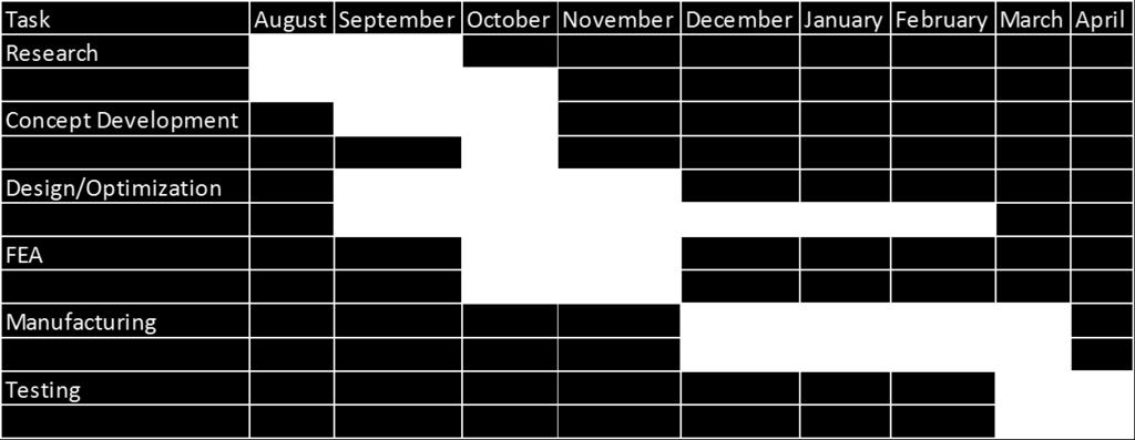
14 APPENDIX E TIMELINE

15 APPENDIX F MANUFACTURING DRAWINGS LOWER CONTROL ARM

16 UPPER CONTROL ARM
17 BALL JOINT CUP

18 THREADED INSERT

19 LOWER CONTROL ARM BUSHING

20 LOWER AND UPPER MOUNTING TABS

21 SHOCK TABS
SAE Mini BAJA: Suspension and Steering
 SAE Mini BAJA: Suspension and Steering By Zane Cross, Kyle Egan, Nick Garry, Trevor Hochhaus Team 11 Progress Report Submitted towards partial fulfillment of the requirements for Mechanical Engineering
SAE Mini BAJA: Suspension and Steering
 SAE Mini BAJA: Suspension and Steering By Zane Cross, Kyle Egan, Nick Garry, Trevor Hochhaus Team 11 Project Progress Submitted towards partial fulfillment of the requirements for Mechanical Engineering
2012 Baja SAE Drivetrain
 2012 Baja SAE Drivetrain A thesis submitted to the Faculty of the Mechanical Engineering Technology Program of the University of Cincinnati in partial fulfillment of the requirements for the degree of
2013 Baja SAE Drivetrain
 2013 Baja SAE Drivetrain A Baccalaureate thesis submitted to the School of Dynamic Systems College of Engineering and Applied Science University of Cincinnati in partial fulfillment of the requirements
SAE Mini BAJA: Suspension and Steering
 SAE Mini BAJA: Suspension and Steering By Zane Cross, Kyle Egan, Nick Garry, Trevor Hochhaus Team 11 Problem Formulation and Project Plan Report Submitted towards partial fulfillment of the requirements
2014 University of Cincinnati Baja SAE Braking System
 2014 University of Cincinnati Baja SAE Braking System A Baccalaureate thesis submitted to the School of Dynamic Systems College of Engineering and Applied Science University of Cincinnati In partial fulfillment
Design and Analysis of suspension system components
 Design and Analysis of suspension system components Manohar Gade 1, Rayees Shaikh 2, Deepak Bijamwar 3, Shubham Jambale 4, Vikram Kulkarni 5 1 Student, Department of Mechanical Engineering, D Y Patil college
SAE Mini Baja: Suspension and Steering
 SAE Mini Baja: Suspension and Steering Project Proposal Zane Cross, Kyle Egan, Nick Garry, Trevor Hochhaus NAU December 3, 2014 Overview 2 Problem Definition and Project Plan Concept Generation Design
SAE Mini Baja. Final Presentation. Benjamin Bastidos, Jeramie Goodwin, Eric Lockwood Anthony McClinton, Caizhi Ming, Ruoheng Pan May 2, 2014
 SAE Mini Baja Final Presentation Benjamin Bastidos, Jeramie Goodwin, Eric Lockwood Anthony McClinton, Caizhi Ming, Ruoheng Pan May 2, 2014 Overview Project Introduction Need Statement Frame Design and
International Journal of Scientific & Engineering Research Volume 8, Issue 10, October-2017 ISSN
 309 Design and Analysis of Suspension System for a Formula Style Car Anshul Kunwar 1, Mohit Nagpal 2, Geetanjali Raghav 3 1 Student, Department of Mechanical Engineering, DIT University, Dehradun-248009
Design And Development Of Roll Cage For An All-Terrain Vehicle
 Design And Development Of Roll Cage For An All-Terrain Vehicle Khelan Chaudhari, Amogh Joshi, Ranjit Kunte, Kushal Nair E-mail : khelanchoudhary@gmail.com, amogh_4291@yahoo.co.in,ranjitkunte@gmail.com,krockon007@gmail.com
SAE Mini Baja By Ahmed Alnattar, Neil Gehr, and Matthew Legg Team 11
 SAE Mini Baja 2014-2015 By Ahmed Alnattar, Neil Gehr, and Matthew Legg Team 11 Final Report Document April 22, 2015 Submitted towards partial fulfillment of the requirements for Mechanical Engineering
Design of Suspension and Steering system for an All-Terrain Vehicle and their Interdependence
 Design of Suspension and Steering system for an All-Terrain Vehicle and their Interdependence Saurabh Wanganekar 1, Chinmay Sapkale 2, Priyanka Chothe 3, Reshma Rohakale 4,Samadhan Bhosale 5 1 Student,Department
SAE Baja - Drivetrain
 SAE Baja - Drivetrain By Ricardo Inzunza, Brandon Janca, Ryan Worden Team 11 Engineering Analysis Document Submitted towards partial fulfillment of the requirements for Mechanical Engineering Design I
2016 Baja SAE Series Frame Design
 2016 Baja SAE Series Frame Design A Baccalaureate thesis submitted to the Department of Mechanical and Materials Engineering College of Engineering and Applied Science University of Cincinnati in partial
ASME Human Powered Vehicle
 ASME Human Powered Vehicle By Yousef Alanzi, Evan Bunce, Cody Chenoweth, Haley Flenner, Brent Ives, and Connor Newcomer Team 14 Mid-Point Review Document Submitted towards partial fulfillment of the requirements
2017 Baja SAE Competition
 2017 Baja SAE Competition Meet the Team Enrique DeLeon Manjula Hodekar Keith Hernandez Mechanical Lead Public Relations Design Lead Logistics Team Lead Project Management Instructor: Dr. Raresh Pascali
SAE Baja - Drivetrain
 SAE Baja - Drivetrain By Ricardo Inzunza, Brandon Janca, Ryan Worden Team 11A Concept Generation and Selection Document Submitted towards partial fulfillment of the requirements for Mechanical Engineering
Orbital Test Stand. By Mary Begay, Brett Booen, Calvin Boothe, James Ellis and Nicholas Garcia. Team 7. Project Proposal Document
 Orbital Test Stand By Mary Begay, Brett Booen, Calvin Boothe, James Ellis and Nicholas Garcia Team 7 Project Proposal Document Submitted towards partial fulfillment of the requirements for Mechanical Engineering
1. SPECIFICATIONS 2. WHEEL ALIGNMENT Front Suspension. (gas type) Rear Suspension. (gas type)
 Rear Suspension. (gas type)") 441101 053 1. SPECIFICATIONS Front Suspension Rear Suspension Description Suspension type Spring type Shock absorber type Stabilizer bar type Suspension type Spring type Shock absorber type Stabilizer
441101 053 1. SPECIFICATIONS Front Suspension Rear Suspension Description Suspension type Spring type Shock absorber type Stabilizer bar type Suspension type Spring type Shock absorber type Stabilizer
KINEMATICS OF REAR SUSPENSION SYSTEM FOR A BAJA ALL-TERRAIN VEHICLE.
 International Journal of Mechanical Engineering and Technology (IJMET) Volume 8, Issue 8, August 2017, pp. 164 171, Article ID: IJMET_08_08_019 Available online at http://www.iaeme.com/ijmet/issues.asp?jtype=ijmet&vtype=8&itype=8
Chrysler A-Body Tubular A-Arms Installation Instructions A-ARM INSTALLATION
 1967-1976 Dodge Demon 1112 67-72 Chrysler A-Body Tubular A-Arms Installation Instructions Thank you for your purchase of this Hotchkis Performance product. Your A-Arm set was designed with the performance
Wheel Alignment Defined
 Wheel Alignment Defined While it's often referred to simply as an "alignment" or "wheel alignment," it's really complex suspension angles that are being measured and a variety of suspension components
University of Wisconsin-Platteville Formula SAE Design Report
 2012-2013 University of Wisconsin-Platteville Formula SAE Design Report Introduction The 2012-2013 University of Wisconsin-Platteville Formula SAE Team is competing in Formula SAE, Nebraska, for the second
1. SPECIFICATIONS 2. WHEEL ALIGNMENT
 441101 083 1. SPECIFICATIONS Front Suspension Rear Suspension Description Suspension type Spring type Shock absorber type Stabilizer bar type Suspension type Spring type Shock absorber type Stabilizer
DOUBLE WISHBONE SUSPENSION SYSTEM
 International Journal of Mechanical Engineering and Technology (IJMET) Volume 8, Issue 5, May 2017, pp. 249 264 Article ID: IJMET_08_05_027 Available online at http:// http://www.iaeme.com/ijmet/issues.asp?jtype=ijmet&vtype=8&itype=5
PRESEASON CHASSIS SETUP TIPS
 PRESEASON CHASSIS SETUP TIPS A Setup To-Do List to Get You Started By Bob Bolles, Circle Track Magazine When we recently set up our Project Modified for our first race, we followed a simple list of to-do
COWBOY MOTORSPORTS SENIOR DESIGN Scott Dick Garrett Dollins Logan Gary
 COWBOY MOTORSPORTS SENIOR DESIGN 2016-2017 Scott Dick Garrett Dollins Logan Gary 2016-2017 ASABE INTERNATIONAL QUARTER SCALE TRACTOR STUDENT DESIGN COMPETITION COMPETITION OVERVIEW Design report 500 pts
08-09 Suspension Design Analysis
 Jonathan Peyton Independent Design Study 08-09 Suspension Design Analysis Summary: The chasiss of the 08-09 car was redesigned to have a shorter wheelbase by two inches and a wider rear track by two and
SAE Mini Baja. Frame Team. Ahmed Alnattar, Neil Gehr, Matthew Legg. Project Proposal
 SAE Mini Baja Frame Team Project Proposal Ahmed Alnattar, Neil Gehr, Matthew Legg 12-3-14 1 Overview Introduction Customer s Needs and Project Goals Constraints, Objectives, QFD, and Timeline Concept Generation
RHINO SUSPENSION SYSTEM INSTALLATION INSTRUCTIONS
 PARTS INCLUDED: 2 FRONT UPPER A-ARMS 2 FRONT LOWER A-ARMS 2 UNI-BALL JOINTS 2 UNI-BALL JOINT STUDS 2 UNI-BALL JOINT CAPS 2 RETAINING RINGS 1 FRONT SHOCK ASSEM. 2 DELRON STEERING STOPS 2 SHOCK MOUNT SPACERS
A double-wishbone type suspension is used in the front. A multi-link type suspension is used in the rear. Tread* mm (in.) 1560 (61.
 1560 (61.") CHASSIS SUSPENSION AND AXLE CH-69 SUSPENSION AND AXLE SUSPENSION 1. General A double-wishbone type suspension is used in the front. A multi-link type suspension is used in the rear. 08D0CH111Z Specifications
CHASSIS SUSPENSION AND AXLE CH-69 SUSPENSION AND AXLE SUSPENSION 1. General A double-wishbone type suspension is used in the front. A multi-link type suspension is used in the rear. 08D0CH111Z Specifications
Using ABAQUS in tire development process
 Using ABAQUS in tire development process Jani K. Ojala Nokian Tyres plc., R&D/Tire Construction Abstract: Development of a new product is relatively challenging task, especially in tire business area.
SAE Baja Design/Manufacturing Project. (MECET, Design Emphasis)
") 2016-2017 SAE Baja Design/Manufacturing Project Hani Alnakhly Mohnannad Gazzaz Azmi Awari Turki Al-Rashid Sultan Alshammari Abraham Ittycheri (MECET, Design Emphasis) (MECET, Design Emphasis) (MECET, Design
2016-2017 SAE Baja Design/Manufacturing Project Hani Alnakhly Mohnannad Gazzaz Azmi Awari Turki Al-Rashid Sultan Alshammari Abraham Ittycheri (MECET, Design Emphasis) (MECET, Design Emphasis) (MECET, Design
SAE Baja: Suspension & Steering Benjamin Bastidos, Victor Cabilan, Jeramie Goodwin, William Mitchell, Eli Wexler
 SAE Baja: Suspension & Steering Benjamin Bastidos, Victor Cabilan, Jeramie Goodwin, William Mitchell, Eli Wexler Wednesday, October 9, 2013 Overview Introduction Operating Environment Recognizing the Need
Timing the 9N/2N Steering Sector Gears
 Timing the 9N/2N Steering Sector Gears by John Korschot - www.johnsoldiron.com (May 2010) The procedure for timing a set of steering gears in the 9/2n tractors is published in the I&T FO4 shop manual.
Signature redacted. Signature redacted- - JUL LIBRARIES
 Design and Analysis of the Front Suspension Geometry and Steering System for a Solar Electric Vehicle by Bruce Arensen Submitted to the Department of Mechanical Engineering in Partial Fulfillment of the
DESIGN AND ANALYSIS OF TUBULAR CHASSIS OF GO-KART
 DESIGN AND ANALYSIS OF TUBULAR CHASSIS OF GO-KART Prashant Thakare 1, Rishikesh Mishra 2, Kartik Kannav 3, Nikunj Vitalkar 4, Shreyas Patil 5, Snehal Malviya 6 1 UG Students, Department of Mechanical Engineering,
Design and Front Impact Analysis of Rollcage
 International Conference on Challenges and Opportunities in Mechanical Engineering, Industrial Engineering and Management Studies 7 Design and Front Impact Analysis of Rollcage Gautam Yadav and Ankit Jain
Tech Tip: Trackside Tire Data
 Using Tire Data On Track Tires are complex and vitally important parts of a race car. The way that they behave depends on a number of parameters, and also on the interaction between these parameters. To
ME 455 Lecture Ideas, Fall 2010
 ME 455 Lecture Ideas, Fall 2010 COURSE INTRODUCTION Course goal, design a vehicle (SAE Baja and Formula) Half lecture half project work Group and individual work, integrated Design - optimal solution subject
Off Road Innovations. Design of an Off-Road Suspension and Steering System. EN Mechanical Design Project II - Progress Report 1
 Off Road Innovations Design of an Off-Road Suspension and Steering System EN 8926 - Mechanical Design Project II - Progress Report 1 Andrew Snelgrove 200832467 Calvin Holloway 200814416 Jeremy Sheppard
Over The Knuckle Steering PART #: RS-SC300-UV APPLICATION: XJ,TJ,ZJ
 Rusty s Off-Road Products 7161 Steele Station Road Rainbow City, AL 35906 Phone: (256) 442-0607 FAX: (256) 442-0017 Web Site: www.rustysoffroad.com Over The Knuckle Steering PART #: RS-SC300-UV APPLICATION:
Design and optimization of Double wishbone suspension system for ATVs
 Design and optimization of Double wishbone suspension system for ATVs Shantanu Garud 1, Pritam Nagare 2, Rohit Kusalkar 3, Vijaysingh Gadhave 4, Ajinkya Sawant 5 1,2,3,4Dept of Mechanical Engineering,
CHASSIS DYNAMICS TABLE OF CONTENTS A. DRIVER / CREW CHIEF COMMUNICATION I. CREW CHIEF COMMUNICATION RESPONSIBILITIES
 CHASSIS DYNAMICS TABLE OF CONTENTS A. Driver / Crew Chief Communication... 1 B. Breaking Down the Corner... 3 C. Making the Most of the Corner Breakdown Feedback... 4 D. Common Feedback Traps... 4 E. Adjustment
Between the Road and the Load Calculate True Capacity Before Buying Your Next Trailer 50 Tons in the Making
 Between the Road and the Load Calculate True Capacity Before Buying Your Next Trailer By Troy Geisler, Vice President of Sales & Marketing, Talbert Manufacturing Long before a single load is booked or
Solar Boat Capstone Group
 Solar Boat Capstone Group Design Team Chris Maccia, Jeff Tyler, Matt Knight, Carla Pettit, Dan Sheridan Design Advisor Prof. M. Taslim Abstract Every year Solar Splash, the IEEE World Championship of intercollegiate
New Frontier in Energy, Engineering, Environment & Science (NFEEES-2018 ) Feb
 Feb") RESEARCH ARTICLE OPEN ACCESS DESIGN AND IMPACT ANALYSIS OF A ROLLCAGE FOR FORMULA HYBRID VEHICLE Aayush Bohra 1, Ajay Sharma 2 1(Mechanical department, Arya College of Engineering & I.T.,kukas, Jaipur)
RESEARCH ARTICLE OPEN ACCESS DESIGN AND IMPACT ANALYSIS OF A ROLLCAGE FOR FORMULA HYBRID VEHICLE Aayush Bohra 1, Ajay Sharma 2 1(Mechanical department, Arya College of Engineering & I.T.,kukas, Jaipur)
Wheel Alignment Fundamentals
 CHAPTER 67 Wheel Alignment Fundamentals OBJECTIVES Upon completion of this chapter, you should be able to: Describe each wheel alignment angle. Tell which alignment angles cause wear or pull. KEY TERMS
SAE Baja: Project Proposal Suspension and Steering
 SAE Baja: Project Proposal Suspension and Steering Benjamin Bastidos, Victor Cabilan, Jeramie Goodwin, William Mitchell, Eli Wexler Wednesday, November 20, 2013 Overview Introduction Concept Generation
SAE Mini Baja West. By Ahmed Alnattar, Neil Gehr, and Matthew Legg Team 11. Concept Generation Document
 SAE Mini Baja West By Ahmed Alnattar, Neil Gehr, and Matthew Legg Team 11 Concept Generation Document Submitted towards partial fulfillment of the requirements for Mechanical Engineering Design I Fall
Design and Optimization of Suspension System of All Terrain Vehicle
 Design and Optimization of Suspension System of All Terrain Vehicle Abhishek Rajput 1, Bhupendra Kasana 2, Dhruv Sharma 3, Chandan B.B 4 1, 2, 3 Under Graduate students, Dept. of Mechanical Engineering,
ROLL CENTER You can adjust the front and rear roll centers of the XB8 by changing the mounting locations of various components.
 Your XRAY XB8 luxury nitro buggy is a top competition, precision racing machine that features multiple adjustments that allow you to set up for any track condition. The XB8 includes innovative set-up features
NEW DESIGN AND DEVELELOPMENT OF ESKIG MOTORCYCLE
 NEW DESIGN AND DEVELELOPMENT OF ESKIG MOTORCYCLE Eskinder Girma PG Student Department of Automobile Engineering, M.I.T Campus, Anna University, Chennai-44, India. Email: eskindergrm@gmail.com Mobile no:7299391869
Hitch Mounted Carrier for a Yamaha Blaster ATV JAMES DROIT
 Hitch Mounted Carrier for a Yamaha Blaster ATV by JAMES DROIT Submitted to the MECHANICAL ENGINEERING TECHNOLOGY DEPARTMENT In Partial Fulfillment of the Requirements for the Degree of Bachelor of Science
Mtd kit: Honda Engine Conversions for classic minis. mtd installation manual For Classic minis
 Mtd kit: Honda Engine Conversions for classic minis mtd installation manual For Classic minis 1959 2001 Dear Customer, We welcome you to the Honda Powered Mini World. Thank you and Congratulations for
Rear Camber Correction for Acura NSX
 Rear Camber Correction for 1991-2005 Acura NSX A Baccalaureate thesis submitted to the Department of Mechanical and Materials Engineering College of Engineering and Applied Science University of Cincinnati
F.I.R.S.T. Robotic Drive Base
 F.I.R.S.T. Robotic Drive Base Design Team Shane Lentini, Jose Orozco, Henry Sick, Rich Phelan Design Advisor Prof. Sinan Muftu Abstract F.I.R.S.T. is an organization dedicated to inspiring and teaching
SAE Baja - Drivetrain
 SAE Baja - Drivetrain Project Proposal Ricardo Inzunza, Brandon Janca, Ryan Worden December 3, 2014 Overview Introduction Needs and Constraints QFD/HOQ Problem Definition and Project Goal Transmission
2012 Dalhousie University Formula SAE Design Report
 Dalhousie University Car #47 - Formula SAE Michigan fsae@dal.ca Introduction 2012 Dalhousie University Formula SAE Design Report The 2012 Dalhousie University Formula SAE Team is competing in Formula SAE,
Kinematic Analysis of Roll Motion for a Strut/SLA Suspension System Yung Chang Chen, Po Yi Tsai, I An Lai
 Kinematic Analysis of Roll Motion for a Strut/SLA Suspension System Yung Chang Chen, Po Yi Tsai, I An Lai Abstract The roll center is one of the key parameters for designing a suspension. Several driving
Increase performance of all-terrain vehicle by tuning of various components
 Increase performance of all-terrain vehicle by tuning of various components Bhavdeep Trivedi Marut Patel Deep Patel Ripen Shah Asst. Professor, Mechanical Department, Silver Oak College of Engg. & Tech.,
Installation Procedure GR40 S197 SLA Front Suspension System (Does not include Aluminum Spindle and Hub Instructions)
") Installation Procedure GR40 S197 SLA Front Suspension System (Does not include Aluminum Spindle and Hub Instructions) Please take the time and read these instructions first! The GR40 S197 system is designed
Installation Procedure GR40 S197 SLA Front Suspension System (Does not include Aluminum Spindle and Hub Instructions) Please take the time and read these instructions first! The GR40 S197 system is designed
Cane Creek Double Barrel Instructions
 Cane Creek Double Barrel Instructions Congratulations on your purchase of the Cane Creek Double Barrel rear shock. Developed in partnership with Öhlins Racing, the Double Barrel brings revolutionary suspension
BIG BAR SOFT SPRING SET UP SECRETS
 BIG BAR SOFT SPRING SET UP SECRETS Should you be jumping into the latest soft set up craze for late model asphalt cars? Maybe you will find more speed or maybe you won t, but either way understanding the
JEEP JK 4 LONGARM. Tools Needed: Thank you for choosing Rough Country for your suspension needs.
 921786000 Thank you for choosing Rough Country for your suspension needs. JEEP JK 4 LONGARM Rough Country recommends a certified technician install this system. In addition to these instructions, professional
Remote Control Helicopter. Engineering Analysis Document
 Remote Control Helicopter By Abdul Aldulaimi, Travis Cole, David Cosio, Matt Finch, Jacob Ruechel, Randy Van Dusen Team 04 Engineering Analysis Document Submitted towards partial fulfillment of the requirements
Solar Car Suspension Design Considerations for achieving an efficient and stable vehicle
 Innovators Educational Foundation Solar Car Suspension Design Considerations for achieving an efficient and stable vehicle Solar Car Conference, February 1-3, 2019 Southern Illinois University, Edwardsville,
Racing Tires in Formula SAE Suspension Development
 The University of Western Ontario Department of Mechanical and Materials Engineering MME419 Mechanical Engineering Project MME499 Mechanical Engineering Design (Industrial) Racing Tires in Formula SAE
PYRTE. Building The Front Axle, Fork and Steering
 PYRTE Building The Front Axle, Fork and Steering The front axle on this traction engine is a very simple affair, in that it is a rectangular steel rod, sat on edge, with a pivot in the centre, which is
Steeda Sport Mustang Lowering Springs (2005+) - Installation Instructions
 - Installation Instructions") Steeda Sport Mustang Lowering Springs (2005+) - Installation Instructions The below installation instructions work for the following products: Steeda Sport Mustang Lowering Springs (2005+) Please read
Steeda Sport Mustang Lowering Springs (2005+) - Installation Instructions The below installation instructions work for the following products: Steeda Sport Mustang Lowering Springs (2005+) Please read
Chassis. Introduction. Design Objectives
 Chassis Introduction Purpose and Goals The chassis is the backbone of the Mini-Baja; it must support all the car s subassemblies as well as protect the driver. The chassis design is crucial to the success
DESIGN AND DEVELOPMENT OF IC ENGINE GO-KART
 DESIGN AND DEVELOPMENT OF IC ENGINE GO-KART AkshayB. Khot 1, KunalJ. Mahekar 2, VaibhavJ. Mahekar 3, GurunathS. Patil 4, MohanishM. Patil 5, Prof. S. P. Jarag 6 BE Student, Department of Mechanical Engineering,
Design, Modelling & Analysis of Double Wishbone Suspension System
 Design, Modelling & Analysis of Double Wishbone Suspension System 1 Nikita Gawai, 2 Deepak Yadav, 3 Shweta Chavan, 4 Apoorva Lele, 5 Shreyash Dalvi Thakur College of Engineering & Technology, Kandivali
Design of Formula SAE Suspension
 SAE TECHNICAL PAPER SERIES 2002-01-3310 Design of Formula SAE Suspension Badih A. Jawad and Jason Baumann Lawrence Technological University Reprinted From: Proceedings of the 2002 SAE Motorsports Engineering
Tools Needed: Class 8.8 Class MM 55ft/lbs 75ft/lbs 14MM 85ft/lbs 120ft/lbs 16MM 130ft/lbs 165ft/lbs 18MM 170ft/lbs 240ft/lbs
 921788000 JEEP JK 6 LONGARM Rough Country recommends a certified technician install this system. In addition to these instructions, professional knowledge of disassemble/reassembly procedures as well as
Chicane Coilover Kit For '64 to '72 Chevelle/ A Body. Installation Instructions
 Nov 3, 2017 Chicane Coilover Kit For '64 to '72 Chevelle/ A Body Installation Instructions Actual parts may vary from photo depending on application. 1 P a g e The following instructions are intended for
, Toyota Tacoma 3 SST Lift Kit
 69-5112, 69-5212 Toyota Tacoma 3 SST Lift Kit IF your ReadyLIFT product has a damaged or missing part, please contact customer service directly and a new replacement part will be sent to you immediately.
Stationary Bike Generator System
 Central Washington University ScholarWorks@CWU All Undergraduate Projects Undergraduate Student Projects Spring 2017 Stationary Bike Generator System Rakan Alghamdi Central Washington University, rk_rk11@hotmail.com
Torque steer effects resulting from tyre aligning torque Effect of kinematics and elastokinematics
 P refa c e Tyres of suspension and drive 1.1 General characteristics of wheel suspensions 1.2 Independent wheel suspensions- general 1.2.1 Requirements 1.2.2 Double wishbone suspensions 1.2.3 McPherson
Part # GM G Body Air Suspension System
 350 S. St. Charles St. Jasper, In. 47546 Ph. 812.482.2932 Fax 812.634.6632 www.ridetech.com Part # 11320298 78-88 GM G Body Air Suspension System Front Components: 1 11323001 HQ Series Front Shockwaves
Surface- and Pressure-Dependent Characterization of SAE Baja Tire Rolling Resistance
 Surface- and Pressure-Dependent Characterization of SAE Baja Tire Rolling Resistance Abstract Cole Cochran David Mikesell Department of Mechanical Engineering Ohio Northern University Ada, OH 45810 Email:
ISSN: [Patil et al., 5(10): October, 2016] Impact Factor: 4.116
![ISSN: [Patil et al., 5(10): October, 2016] Impact Factor: 4.116](/thumbs/83/88212336.jpg "ISSN: [Patil et al., 5(10): October, 2016] Impact Factor: 4.116") IJESRT INTERNATIONAL JOURNAL OF ENGINEERING SCIENCES & RESEARCH TECHNOLOGY DESIGN AND ANALYSIS OF TELESCOPIC HALFSHAFT FOR AN ALL-TERRAIN VEHICLE (ATV) Chirag Patil *, Sandeep Imale, Kiran Hiware, Sumeet
IJESRT INTERNATIONAL JOURNAL OF ENGINEERING SCIENCES & RESEARCH TECHNOLOGY DESIGN AND ANALYSIS OF TELESCOPIC HALFSHAFT FOR AN ALL-TERRAIN VEHICLE (ATV) Chirag Patil *, Sandeep Imale, Kiran Hiware, Sumeet
Mini Baja Advisory Presentation May 2, 2008
 Mini Baja Advisory Presentation May 2, 2008 Presenter: Mark Bell Accompanied by Baja Team 83 Member Jerrod Bohannon Table of Contents Overview of Competition Design Conditions Grading Criteria Design Concepts
INSTALLATION INSTRUCTIONS Mopar Performance 2 Lift System 2009 and Newer Dodge Ram 1500 (DS) 4WD PART NUMBER P
 4WD PART NUMBER P") INTRODUCTION Installation requires a professional mechanic. Prior to beginning, inspect the vehicle s steering, driveline, and brake systems, paying close attention to the suspension link arms and bushings,
INTRODUCTION Installation requires a professional mechanic. Prior to beginning, inspect the vehicle s steering, driveline, and brake systems, paying close attention to the suspension link arms and bushings,
Introduction: Problem statement
 Introduction: Problem statement The goal of this project is to develop a catapult system that can be used to throw a squash ball the farthest distance and to be able to have some degree of accuracy with
2015 Project Plan Report
 2015 Project Plan Report Jack Haiston, jhaiston@outlook.com, (970) 420-0943 Tyler Norris, tnorris93@me.com, (513) 288-0258 Loren Christensen, lchristensen92@gmail.com, (719) 580-0750 Nathan Houser, nthnhsr@rams.colostate.edu,
AMT Motorsport C7 Corvette Camber Kit User s Guide. 8 Upper Control Arm Studs and hardware for rear upper control arm adjustments
 AMT Motorsport C7 Corvette Camber Kit User s Guide Thank you for purchasing the AMT Motorsport Camber Kit for the C7 Corvette. We believe this is the most versatile camber kit available on the market,
Welcome and enjoy tuning your Manitou ABS+ Compression Damping System! Purposefully engineered to raise your expectations.
 Welcome and enjoy tuning your Manitou ABS+ Compression Damping System! Purposefully engineered to raise your expectations. PLEASE READ SERVICE INSTRUCTIONS PRIOR TO BEGINNING WORK. While revalving your
University of Alaska Anchorage Society of Automotive Engineers 2015 Baja Team
 University of Alaska Anchorage Society of Automotive Engineers 2015 Baja Team ME A438 Fall 2014 Senior Design Report Design Team Members: Galen Baumgartner Devon Jones Jun Mendoza Valisa Hansen Elena Stutzer
Chevy Nova Pro-Touring Front Suspension Installation Instructions
 1962-1967 Chevy Nova Pro-Touring Front Suspension Installation Instructions 1-800-984-6259 www.totalcostinvolved.com 1 Pro-Touring Clip A-Arm Assembly Sway Bar Assembly Fender Panel Kit 8 7/16-20 * 1 ¼
SAE Mini Baja Drivetrain
 SAE Mini Baja Drivetrain By: Abdulrahman Almuflih, Andrew Perryman, Caizhi Ming, Zan Zhu, Ruoheng Pan Team 02 Mid-point review REPORT Submitted towards partial fulfillment of the requirements for Mechanical
Development of a Rubber Disc Piston Seal for the Mahadaga Handpump Peter Govey, Christopher Claassen, Joseph Longenecker Messiah College 2006
 Development of a Rubber Disc Piston Seal for the Mahadaga Handpump Peter Govey, Christopher Claassen, Joseph Longenecker Messiah College 2006 Abstract We developed a new concept for a piston seal that
Test Plans & Test Results
 P10227 Variable Intake System for FSAE Race Car Test Plans & Test Results By: Dave Donohue, Dan Swank, Matt Smith, Kursten O'Neill, Tom Giuffre Table of contents 1. MSD I: WKS 8-10 PRELIMINARY TEST PLAN...
PROJECT IDEA SUBMISSION
 PROJECT IDEA SUBMISSION Team Contacts - 1 st person listed serves as the point of contact with Professor Nelson - Initial team size may be from 1 to 6 members (all members must agree to have their name
DESIGN AND DEVELOPMENT OF A SUSPENSION SYSTEM USED IN ROUGH- TERRAIN VEHICLE CONTROL FOR VIBRATION SUPPRESSION IN PLANETARY EXPLORATION
 DESIGN AND DEVELOPMENT OF A SUSPENSION SYSTEM USED IN ROUGH- TERRAIN VEHICLE CONTROL FOR VIBRATION SUPPRESSION IN PLANETARY EXPLORATION Arvin Niro College of Engineering University of Hawaiʽi at Mānoa
Technical Math 2 Lab 3: Garage Door Spring 2018
 Name: Name: Name: Name: As you may have determined the problem is a broken spring (clearly shown on the left in the picture below) which needs to be replaced. I. Garage Door Basics: Common residential
2. MEASURE VEHICLE HEIGHT. (b) Measure the vehicle height. Measurement points: C: Ground clearance of front wheel center
 Measure the vehicle height. Measurement points: C: Ground clearance of front wheel center") ADJUSTMENT If the wheel alignment has been adjusted, and if suspension or underbody components have been removed/installed or replaced, be sure to perform the following initialization procedure in order
ADJUSTMENT If the wheel alignment has been adjusted, and if suspension or underbody components have been removed/installed or replaced, be sure to perform the following initialization procedure in order
Feb 22, 2018 '67-69 Camaro & '68-74 Nova Bumpsteer Adjustment Kit
 Feb 22, 2018 '67-69 Camaro & '68-74 Nova Bumpsteer Adjustment Kit 10552 The following instructions are intended for professional installers. Speedtech Performance assumes NO responsibility for the installation
4.4. Forces Applied to Automotive Technology. The Physics of Car Tires
 Forces Applied to Automotive Technology Throughout this unit we have addressed automotive safety features such as seat belts and headrests. In this section, you will learn how forces apply to other safety