Introduction: Problem statement
|
|
|
- Marcus Shields
- 6 years ago
- Views:
Transcription
1 Introduction: Problem statement The goal of this project is to develop a catapult system that can be used to throw a squash ball the farthest distance and to be able to have some degree of accuracy with the mechanism. In order for this project to be successful at all, the catapult must at least work and actually through the ball. The degree of success will be determined by how accurate and how far we can get the catapult to through the ball. The design of the catapult mechanism has several design constraints placed on it. First the mechanism used for this catapult system must use at least a four-bar mechanism to accomplish the task. It may have any number of bars in the mechanism as long as it is greater than or equal to four. The catapult mechanism will use only one specified motor to power the system. Another constraint on the catapult mechanism is that it must be made entirely from wood. This mechanism cannot start with any potential energy stored in the system before the motor is turned on. The motor may be used to build up potential energy but may not be run for more than 30 seconds before actually firing the catapult system. Finally, the entire mechanism has to meet a space constraint of 2 by 2 and cannot leave that space while in operation. The following is a list of the project rules: The squash ball can be hand-loaded during the competition. However, after loading, teams will be permitted only to turn on the switch connecting power to the motor. Distances will be measured from the edge of the table (Start Plane) to the point of impact in centimeters. Each team will get three tries and the sum of the three distances (measured in cm) will serve as the team s score. A rematch may be
2 required to settle the decision in case of a tie (which will be solely at the discretion of Dr. Krovi) All parts should be taken from student s houses/apartments/garages, machine shops, scrap yards, etc. Purchases need to be kept minimal, if any. All devices will undergo strict safety inspections prior to the competition. If anyone in the MAE machine shop or Dr. Krovi feels that the mechanism is unsafe, it will not be allowed to compete no exceptions.
3 Idea Generation The first action we took as a group was to hold a brainstorming session to generate as many ideas as we could. Everyone came up with there own ideas for how to design the catapult system. We then met and went over the design ideas and evaluated how well we thought they were. After going through the initial concepts we considered and focused on three different designs for this mechanism. The first design is a system of springs that are stretched using a four bar setup. The four bar setup has a string connected to it which is wound onto a pulley by the motor. The springs store the potential energy as the string is wound onto the pulley. The ball is placed in front of a spring loaded platform that is pulled back and loaded by the four-bar mechanism. Once the string is released the spring s contract and the ball is fired. Figure 1

4 Another design that we considered is a design that resembles a BB gun. The motor is connected to a four bar-slider mechanism. When the input link is rotated by the motor, the four bar-slider mechanism compresses a spring. This preloads the mechanism by storing potential energy behind that platform. Once the mechanism releases, the spring forces the platform up and fires the ball. Figure 2 Design concept 3 is an earlier version of the design that we decided to use for this mechanism. We have since decided to move the location of the motor and string loading the system. This version of our four-bar catapult uses a rubber band to store the potential energy of the mechanism. The string is connected to the throwing arm and then wound onto a pulley by the motor. By rotating the throwing link through a determined angle, a load is placed on the input link by the rubber band connected to it. Figure 3

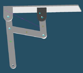
5 Our fourth and final design was similar to the third. We decided to place the motor at the other end of the mechanism. The new configuration is rotated in the opposite direction to through the ball. This setup was used so that longer links could be used and still meet the size requirements. The longer links would give the mechanism more leverage and therefore place more force on the ball. Figure 4
6 Project Development Our group decided to use a four-bar mechanism to construct the catapult. The motor will be use to load a spring connected to one of the links. The motor setup will use a pulley system with a shaft to wind the string onto. Once the link connected to the spring is rotated through a predetermined angle, the system will be triggered to release the string that is loading the mechanism and the mechanism will fire. The construction of the mechanism started after the preliminary analysis was completed. This analysis provided us with the position and lengths of all the links needed. a) Four-bar construction: The complete structure was made from wood. We used 1 x 2 pieces of hardwood for all of the links. All of the links were first cut to their predetermined lengths. The ends of the links were rounded and drilled for the pins to connect them together. The bases that connect the links to the platform were formed from blocks of pine and then screwed to the platform. The platform that the mechanism was mounted to was made from a piece of 1 pine. Since we wanted to have some versatility and control of how far the mechanism would shoot, several holes were drilled in the firing arm. This allowed us to change the amount of force and acceleration that the arm generated. b) Spring setup: At first, we were going to use rubber bands to store potential energy in the mechanism. We later decided against this and chose to use springs instead. The switch to springs was made because we felt that the springs would be more reliable and consistent. Rubber bands would be more likely to weaken and therefore cause variations in the amount of potential energy stored and also be more likely to break. An eye screw was screwed into the bottom side of the input link to connect the spring too. It was placed close to the follower link so that the spring would be steached the maximum possible amount. The other end of the spring was connected to another eye screw that

7 was screwed into the platform. For versatility and more control over the amount of force stored by the spring, several eye screws were placed in a line on the platform. This would allow us to very the amount that the spring was stretched when the mechanism is fired. We used one spring and eye screw distance combination for maximum distance and another spring and eye screw distance combination for shooting 20 feet in the accuracy competition. The spring setup can also be seen in Figure 6. c) Motor, Pulley, String setup: The motor is set up to use a system of two gears that drive a shaft for the string to wind onto. The motor is mounted to the platform using screws. We then mounted a shaft through a block of wood. The output shaft of the motors gearbox is connected to the shaft used to wind the string onto by a system of two gears and a belt to link them. The gears used form a 2:1 ratio so that the torque output of the motor is doubled. This allowed us to be able to store more potential energy by using a stiffer spring. The end of the shaft opposite of the gear has a hole drilled in it so that the string can be tied to it and then wound around the shaft. Figure 5

8 d) Release Mechanism The next major part of our catapult design is the release mechanism. We need a way to release the string from the throwing arm when it reached a predetermined position. This was accomplished by using a pin and a wedge. The pin and put through a loop at the end of the string and the placed into a whole at the end of the throwing arm. The pin was made so that it has a tapered wedge at the one end of it. We then made another tapered wedge out of a 2 x 4 piece of pine. This larger wedge was cut to the height needed and then mounted to the platform. When the motor is turned on, the string winds onto the shaft. Once the string pulls the throwing arm back to the release position, the wedge on the pin and the large wedge mounted to the platform push against each other. This causes the pin to pull out of the throwing arm, firing the mechanism. Figure 6

9 e) Ball holder: The ball holder was made from a coffee scoop. The coffee scoop used was a perfect size to hold and through the ball. The handle of the coffee scoop was mounted to the front side of the throwing arm. The scoop of the coffee scoop was bent back around the end of the throwing arm. Figure 7 f) Power supply, switch setup: The power supply consisted of a large 6-volt battery. We chose to use such a large power supply because we did not want to have to worry about smaller batteries wearing down and causing us to go over the allowed time constraint. The battery was connected to the motor through a small 12-volt switch. Both the power supply and the switch were mounted to the platform.
10 Project Optimization After we had our initial design idea set up and agreed upon, our group then began the task of modifying and optimizing our four bar mechanism. This was accomplished throughout the length of the project up until our competition. The first stage we did was to begin with the solid model constructed on Pro Engineer. This was done to ensure that the parts would fit before prototype construction. These Pro Engineer drawings are located with the simulations and photographs. Our initial analysis included placing a spring or a series of springs to provide forces and accelerate the links and throw the squash ball. We tested different springs to see what kind of forces the motors could store. The first problem was where to put the spring for optimal distance, yet controlled shooting. Link three was chosen because it was ideal from our initial design to fit a spring there and it acts as a driving link for the whole mechanism quite nicely. The spring was fastened by loops at the ends of the springs attached to I hooks in the base and link 3. The next stage in optimization was then testing the springs with our motors. We ended up testing the motor with increasingly higher voltages until our ideal spring was pulled back. This Voltage turned out to be 6 Volts. The motor took 28 seconds to pull back at this power output. A simple on-off switch controlled the motor. With 4.5 volts this turned out to be 35 seconds, a bit too long. The high torque gear was used inside our motor throughout testing. We found it to be able to pull the larger springs back, while the higher speed gear, or the smaller one, just couldn t handle the bigger springs. The next part our team proceeded to optimize was to transmit this power from the motor as efficiently as possible. We started out by building a gearbox, with a pulley and belt to convert the motors power to our spring. Our gearbox was basically a drilled out 2 by 4 chunk with a journal bearing type of friction affecting a steel shaft. This friction was reduced by the use of lubricating grease and it played a small role with little energy losses. This steel shaft transmits power to wind some fishing line on one end and be driven by the belt and pulley from the motors torque on the other end. The end of the shaft was kept in place by the inclusion of a spring to keep our pulleys aligned properly.
11 The fishing line was a 25 lb line, and we found that this snapped in testing once, but was generally OK. The gearbox was held in with two screws on the bottom of our base, which provided adequate stability. This concluded the power transfer development of our project. On the other end of our fishing line was the release mechanism. The release mechanism was the next part we tried to optimize. One of the team members had an idea from a brainstorming session that we use a wedge to provide a horizontal force using a vertical force to release our mechanism. This was the idea we chose to use as our release mechanism. Basically the fishing line wrapped around a peg with a wedged shape machined into it. The wedged shape was circular and the peg inserted into our throwing arm through a drilled hole with the fishing line looped around it. It was circular because when the arm was pulled back we wanted the other end of our wedge, which was attached to the projects base, to contact it at the desired release height and release the energy in the spring to drive the links and throw the ball. We had to optimize the height that our ground wedge stood at. This was done after the throwing arm wedge was constructed so we could just see how they fit together. Refer to the pictures section for a better look at this design. The next stage of optimizations focused on getting our four-bar to be accurate, make some baskets, and fine tuning its performance. The first optimization includes our modification of the throwing arm for better accuracy. This was achieved by using a key slide in our throwing arm. This was not used for distance however; separate holes drilled into link one connected it to link two with a shaft. The first link was attached to our second link by an adjustable wing- nut type fastener. This angle that the two come together at and the effective link lengths could be changed by an adjustment of the wing nut. We also installed many different I hooks screwed into the base for different spring angles and positions. This modification is what actually helped us shoot 2 out of 3 baskets, although our team knows we should have hit 3. Another modification was the use of a coffee scoop for our ball holder. This helped the release of our ball be smooth by cradling the squash ball, but not too tight. Bending it to give our team the best-arched shot for our baskets optimized the scoop.
12 Solid Edge Motion Stages Simulation of 4 bar Mechanism The starting position in the Figures is when the mechanism is fully loaded before release.
13
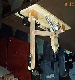
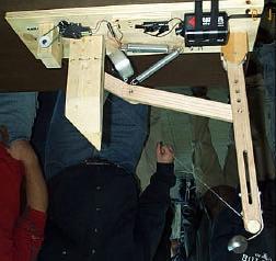
14 Photographs
15 Prototype Solid Edge Velocity and Acceleration Link Analysis Spring Stiffness (Ks) = 5 N/mm Force of Spring (Fs) = 20 N Link 1: Angular Velocity Angular Vel - Y (deg/sec) Time (sec) Angular Accel - Y (deg/sec**2) Angular Acceleration Time (sec) Link 2: Angular Vel - Y (deg/sec) Time (sec) Angular Accel - Y (deg/sec**2) Time (sec) Link 3: Angular Vel - Y (deg/sec) Time (sec) Angular Accel - Y (deg/sec**2) Time (sec)
16 Future Improvements A lot was learned by designing, constructing and testing our catapult. One of the important things that we realized and learned was how our design and setup could be improved. Given the time and opportunity to make improvements on our catapult mechanism, these are a few of the first changes that we would work on. The first improvement that we would make would be to make full use of the 30-second time constraint. Our mechanism was taking an average of 24 seconds before releasing. If we utilized the full 30 seconds allowed, then we could store more potential energy and therefore launch the ball farther than we did. It was apparent that the motor had more than enough torque to accomplish this. Another possible improvement that we could make to out mechanism would be to use lighter links. The lighter the links are, the higher the energy is that actually goes into throwing the ball instead of accelerating the links. Our links could either be made from thinner pieces of wood or slotted in the center the remove weight from them. A final improvement that we could possibly make to our mechanism would be to adjust the height of the large wedge mounted on the platform. If the height of the wedge were a little lower of moved further back, then the throwing arm could be pulled even further back. This would cause the spring to stretch more and store more potential energy.
17 Conclusion and final Results During the competition, our mechanism performed as expected. Although, on our first attempt at the furthest distance throw, the release pin came out too soon and resulted in a short throw. During the judging questions and evaluation we were asked how far we expected our mechanism to throw the ball. We predicted a longest through of 30 feet. Our longest through was on the second attempt and hit the 30-foot line. For our third attempt at a distance shot, we decided to use a combination of link and spring placement that we did not intend to. This combination produced a much larger amount of tension in the spring and caused the line to break. We felt that our best accomplishment and a major portion of our design and testing effort was on the accuracy portion of the competition. We setup our catapult to through the ball into a garbage can 20 feet away. Our design turned out to be much more accurate and consistent that we even expected. The catapult threw the ball into the garbage can two out of three times. The only shot that missed the can was the first shot. The first shot was missed purely because of the initial aiming of the catapult. The ball missed the can by about 2 inches to the left but had perfect distance. After the initial miss, the platform was slightly rotated to compensate for the throw to the left of the can and the last two shots went right into the can.
18 Competition results Farthest Distance Shooting Precision Shooting Group Trial Trial Trial Number of Farthest Ranking Successful Shoots A 38.5 ft 37 ft X 38.5 ft 2 2 B 14 ft 30 ft X 30 ft 7 2 C 24 ft 30 ft 32 ft 32 ft 5 1 D 10 ft 12 ft 14 ft 14 ft 12 0 E 25 ft 25 ft 25 ft 25 ft 9 0 F 17.5 ft 18 ft 20 ft 20 ft 10 0 G 38 ft 37 ft 35.5 ft 38 ft 3 1 H 26 ft 31.5 ft 25 ft 31.5 ft 6 0 I 20 ft 10 ft 15 ft 20 ft 10 0 J 18.5 ft 27.5 ft 38 ft 38 ft 3 2 K 60 ft 57.5 ft - 60 ft 1 2 L 24.5 ft 22.5 ft 27 ft 27 ft 8 2 With Group K that threw 60 feet, the average long distance throw was about 32 feet. This makes our longest through about the average of all the groups. Our precision shooting on the other hand was tied for the best. Overall, we had a great time designing, building and competing with out catapult mechanism in this competition. This project does a good job at demonstrating the objective and usefulness of this course.
After Kickoff, we immediately began the design process by reviewing the game rules with the entire team. During this step, we also looked over the
 After Kickoff, we immediately began the design process by reviewing the game rules with the entire team. During this step, we also looked over the field specifications. We continued development by determining
SAE Baja - Drivetrain
 SAE Baja - Drivetrain By Ricardo Inzunza, Brandon Janca, Ryan Worden Team 11A Concept Generation and Selection Document Submitted towards partial fulfillment of the requirements for Mechanical Engineering
Amazing127_RobotCDesignDoc
 Amazing127_RobotCDesignDoc Specifications: -Length 6.6 in -Width 9.7 in -Height 6.6 in Pictures of our robot: Left Side Back Side Right Side Front Side Componets: 1 Small Motor 2 Large Motors 1 Touch Sencor
Newton Scooters TEACHER NOTES. Forces Chapter Project. Materials and Preparation. Chapter Project Overview. Keep Students on Track Section 2
 TEACHER NOTES Lab zonetm Newton Scooters The following steps will walk you through the. Use the hints as you guide your students through planning, construction, testing, improvements, and presentations.
Engineering Fundamentals Final Project Engineering Lab Report
 Engineering Fundamentals Final Project Engineering Lab Report 4/26/09 Tony Carr Christopher Goggans Zach Maxey Matt Rhule Team Section A2-6 Engineering Fundamentals 151 I have read and approved of the
Manipulators. Example 1: The Claw
 Manipulators With these examples we will demonstrate some basic designs to accomplish each of the game piece challenges involved in the 2018 FIRST Global game Energy Impact to: 1. Collect fuel cubes and
ECSE-2100 Fields and Waves I Spring Project 1 Beakman s Motor
 Names _ and _ Project 1 Beakman s Motor For this project, students should work in groups of two. It is permitted for groups to collaborate, but each group of two must submit a report and build the motor
MOUSETRAP VEHICLE 2012 CONSTRUCTION TIPS
 MOUSETRAP VEHICLE 2012 CONSTRUCTION TIPS Bro. Nigel Pratt bronigel@kellenberg.org 1 Dennis Papesh dpapesh@holyangels.cc Many Thanks Thank you to Bobby B. of Magsig Middle School and Patrick B. of Holy
Lockheed Martin. Team IDK Seung Soo Lee Ray Hernandez Chunyu PengHarshal Agarkar
 Lockheed Martin Team IDK Seung Soo Lee Ray Hernandez Chunyu PengHarshal Agarkar Abstract Lockheed Martin has developed several different kinds of unmanned aerial vehicles that undergo harsh forces when
Engineering Design Process for BEST Robotics JANNE ACKERMAN COLLIN COUNTY (COCO) BEST & BEST OF TEXAS ROBOTICS
 BEST & BEST OF TEXAS ROBOTICS") Engineering Design Process for BEST Robotics JANNE ACKERMAN COLLIN COUNTY (COCO) BEST & BEST OF TEXAS ROBOTICS Agenda Getting Started Lessons Learned Design Process Engineering Mechanics 2 Save Time Complete
Engineering Design Process for BEST Robotics JANNE ACKERMAN COLLIN COUNTY (COCO) BEST & BEST OF TEXAS ROBOTICS Agenda Getting Started Lessons Learned Design Process Engineering Mechanics 2 Save Time Complete
Pre Built Competition Description, Rules 2.0 and Guidelines. Competition Date: December 2, 2017 Coordinator: Austin Cwiklik
 Pre Built Competition Description, Rules 2.0 and Guidelines Competition Date: December 2, 2017 Coordinator: Austin Cwiklik Introduction General Competition Overview Procedures Detailed Competition Overview
Orbital Test Stand. By Mary Begay, Brett Booen, Calvin Boothe, James Ellis and Nicholas Garcia. Team 7. Project Proposal Document
 Orbital Test Stand By Mary Begay, Brett Booen, Calvin Boothe, James Ellis and Nicholas Garcia Team 7 Project Proposal Document Submitted towards partial fulfillment of the requirements for Mechanical Engineering
Peg-Harness installation instructions
 Peg-Harness installation instructions I know it s not the easiest thing to do, but PLEASE READ THESE INSTRUCTIONS COMPLETELY so you will understand what you are trying to accomplish before you start drilling
Timing the 9N/2N Steering Sector Gears
 Timing the 9N/2N Steering Sector Gears by John Korschot - www.johnsoldiron.com (May 2010) The procedure for timing a set of steering gears in the 9/2n tractors is published in the I&T FO4 shop manual.
Door Panel Removal & Window Stop Adjustment
 Door Panel Removal & Window Stop Adjustment By: Jeff Wolford Disclaimer: This is simply an article of how I fixed my car. I m not responsible if you break, scratch, or mess up anything following my example.
Folding Shopping Cart Design Report
 Folding Shopping Cart Design Report EDSGN 100 Section 010, Team #4 Submission Date- 10/28/2013 Group Image with Prototype Submitted by: Arafat Hossain, Mack Burgess, Jake Covell, and Connor Pechko (in
ROBOT C CHALLENGE DESIGN DOCUMENT TEAM NAME. Sample Design Document. Bolt EVA. Lightning. RoboGirls. Cloud9. Femmebots
 ROBOT C CHALLENGE DESIGN DOCUMENT TEAM NAME (SELECT TEAM NAME TO NAVIGATE TO THE TEAM S DESIGN DOCUMENT) Sample Design Document Bolt EVA Lightning RoboGirls Cloud9 Femmebots SAMPLE ROBOT C DESIGN DOCUMENT
DESIGN AND DEVELOPMENT OF A SUSPENSION SYSTEM USED IN ROUGH- TERRAIN VEHICLE CONTROL FOR VIBRATION SUPPRESSION IN PLANETARY EXPLORATION
 DESIGN AND DEVELOPMENT OF A SUSPENSION SYSTEM USED IN ROUGH- TERRAIN VEHICLE CONTROL FOR VIBRATION SUPPRESSION IN PLANETARY EXPLORATION Arvin Niro College of Engineering University of Hawaiʽi at Mānoa
RAMPAGE POWER LIFT RAMP
 RAMPAGE POWER LIFT RAMP INSTALLATION AND OPERATING INSTRUCTIONS (3/10/07) The Rampage Power Lift Ramp is the fast, easy, and safe way to load a motorcycle into a truck. One person can load or unload a
No Drill Modern Gas Shock Installation on a 1931 Ford Model A Coupe
 No Drill Modern Gas Shock Installation on a 1931 Ford Model A Coupe Today we are not going to cover something new but just a little insider info in to what we do during our time off at Apex Tool Company.
2012 Baja SAE Drivetrain
 2012 Baja SAE Drivetrain A thesis submitted to the Faculty of the Mechanical Engineering Technology Program of the University of Cincinnati in partial fulfillment of the requirements for the degree of
Newton s First Law. Evaluation copy. Vernier data-collection interface
 Newton s First Law Experiment 3 INTRODUCTION Everyone knows that force and motion are related. A stationary object will not begin to move unless some agent applies a force to it. But just how does the
MLGW 2018 A-BLAZING MODEL SOLAR CAR RACE RULES AND VEHICLE SPECIFICATIONS
 MLGW 2018 A-BLAZING MODEL SOLAR CAR RACE RULES AND VEHICLE SPECIFICATIONS The object of the MLGW A-BLAZING MODEL SOLAR CAR RACE is to design and build a vehicle that will complete a race in the shortest
SunFlower Helicopter Rocket LUNAR Build Session: 9/25/08 By Tom Desmarais
 SunFlower Helicopter Rocket LUNAR Build Session: 9/25/08 By Tom Desmarais Contents of Kit: A. 3 1/16 x1 x11 basswood rotors B. 3 1/16 x2 x2 basswood fins C. 3 1/16 x5/16 x1/2 basswood hold spacer D. 3
SAE Mini BAJA: Suspension and Steering
 SAE Mini BAJA: Suspension and Steering By Zane Cross, Kyle Egan, Nick Garry, Trevor Hochhaus Team 11 Progress Report Submitted towards partial fulfillment of the requirements for Mechanical Engineering
Wireless Digital Repeater (WiDR) network's packaging/ Initial deployment review
 network's packaging/ Initial deployment review") Rochester Institute of Technology RIT Scholar Works Presentations and other scholarship 2006 Wireless Digital Repeater (WiDR) network's packaging/ Initial deployment review Margot Sandy Follow this and
Rochester Institute of Technology RIT Scholar Works Presentations and other scholarship 2006 Wireless Digital Repeater (WiDR) network's packaging/ Initial deployment review Margot Sandy Follow this and
Projector39/Umnitza BMW Headlight & Re-Installation for E39s Predator Angel Eyes, and Lamin-X Installation
 Projector39/Umnitza BMW Headlight & Re-Installation for E39s Predator Angel Eyes, and Lamin-X Installation Now it is time to remove the headlights! Obviously you have to open the hood to do this. 100_3630.jpg
J&M Mustang Adjustable Panhard Rod (05-09) - Installation Instructions
 - Installation Instructions") J&M Mustang Adjustable Panhard Rod (05-09) - Installation Instructions The below installation instructions work for the following products: J&M Mustang Adjustable Panhard Rod (05-09) Please read through
J&M Mustang Adjustable Panhard Rod (05-09) - Installation Instructions The below installation instructions work for the following products: J&M Mustang Adjustable Panhard Rod (05-09) Please read through
Cable Car. Category: Physics: Balance & Center of Mass, Electricity and Magnetism, Force and Motion. Type: Make & Take.
 Cable Car Category: Physics: Balance & Center of Mass, Electricity and Magnetism, Force and Motion Type: Make & Take Rough Parts List: 1 Paperclip, large 2 Paperclips, small 1 Wood stick, 1 x 2 x 6 4 Electrical
ROBOTICS BUILDING BLOCKS
 ROBOTICS BUILDING BLOCKS 2 CURRICULUM MAP Page Title...Section Estimated Time (minutes) Robotics Building Blocks 0 2 Imaginations Coming Alive 5...Robots - Changing the World 5...Amazing Feat 5...Activity
Commitment to Innovation Leads Fairchild International to Launch New AC Scoop Powered by Baldor Products
 Commitment to Innovation Leads Fairchild International to Launch New AC Scoop Powered by Baldor Products 4 Solutions Magazine Number 5 Coal River Energy agreed to field test the first Fairchild AC powered
Embedded system design for a multi variable input operations
 IOSR Journal of Engineering (IOSRJEN) ISSN: 2250-3021 Volume 2, Issue 8 (August 2012), PP 29-33 Embedded system design for a multi variable input operations Niranjan N. Parandkar, Abstract: - There are
2018 KANSAS BEST BREAKOUT SESSIONS
 2018 KANSAS BEST BREAKOUT SESSIONS Tips for Building a Robot Bryan Jaax September 8, 2018 1 ST STEP: READ the RULES and Technical Data Package 2 FOLLOW AN ENGINEERING PROCESS Define the Problem Brainstorm:
RZR 900 spring/shock installation
 RZR 900 spring/shock installation Thank you for purchasing the Shock Therapy Dual Rate Spring Kit for your RZR 900. Your item list: 2 Front upper coil springs, 2 Front lower coil springs, 2 Rear upper
The Car Tutorial Part 2 Creating a Racing Game for Unity
 The Car Tutorial Part 2 Creating a Racing Game for Unity Part 2: Tweaking the Car 3 Center of Mass 3 Suspension 5 Suspension range 6 Suspension damper 6 Drag Multiplier 6 Speed, turning and gears 8 Exporting
Lifting Mechanisms. Example 1: Two Stage Lift
 Lifting Mechanisms The primary scoring method for the 2018 game is to deposit fuel cubes into scoring zones. A manipulator fixed to your robot can deliver fuel cubes into ground level scoring zones, but
2017 FLYSET FTC Workshop. Hosted by
 2017 FLYSET FTC Workshop Hosted by Hardware Topics Session Evan / Abhishek contributed by Austin / Derek Melody / Audrey from FTC team #12810 Agenda Harvester mechanism comparison Shooter mechanism comparison
Speakers and Motors. Three feet of magnet wire to make a coil (you can reuse any of the coils you made in the last lesson if you wish)
") Speakers and Motors We ve come a long way with this magnetism thing and hopefully you re feeling pretty good about how magnetism works and what it does. This lesson, we re going to use what we ve learned
Speakers and Motors We ve come a long way with this magnetism thing and hopefully you re feeling pretty good about how magnetism works and what it does. This lesson, we re going to use what we ve learned
Moddit. How to Install Stance Coilovers on a Subaru
 Moddit How to Install Stance Coilovers on a Subaru BRZ Let's get LOW (and maybe lighter and stiffer suspension)! In this article, we will install Stance ST- ZN6-XS Coilovers on the FRSport Subaru BRZ.
SOFT LANDING GET READY AHEAD OF TIME. MATERIALS (per lander) INTRODUCE THE CHALLENGE (10 minutes)
 INTRODUCE THE CHALLENGE (10 minutes)") SOFT LANDING Photo credit: NASA/J CHALLENGE: Design and build an airbag system that can safely land an egg dropped onto the floor. LEARNING GOALS: Science: Force, potential and kinetic energy, and the
SOFT LANDING Photo credit: NASA/J CHALLENGE: Design and build an airbag system that can safely land an egg dropped onto the floor. LEARNING GOALS: Science: Force, potential and kinetic energy, and the
Course. GNEG 1103 Introduction to Engineering. Assignment. Team Design Project. Project Selected. Solar Powered Stereo Cooler. Project Presentation
 Course GNEG 1103 Introduction to Engineering Assignment Team Design Project Project Selected Solar Powered Stereo Cooler Project Presentation April 23, 2014 Team Members Kenny Callis Ronny Akhaphong Alfredo
EDSGN 100: INTRODUCTION TO ENGINEERING DESIGN Section 204 Team #1 BOX CART
 EDSGN 100: INTRODUCTION TO ENGINEERING DESIGN Section 204 Team #1 BOX CART Submitted by: Chang - http://www.personal.psu.edu/cbl5289/ Vinay Murthy - http://www.personal.psu.edu/vum119/ Aidan Fitzpatrick
Setup Guide and Chassis Tuning Tips (simple version) By Jim Daniels
 By Jim Daniels") This document is released into the public domain and may be reproduced and distributed in its entirety so long as all credit to Jim Daniels remains. If you find this guide helpful please consider donating
This document is released into the public domain and may be reproduced and distributed in its entirety so long as all credit to Jim Daniels remains. If you find this guide helpful please consider donating
University of New Hampshire: FSAE ECE Progress Report
 University of New Hampshire: FSAE ECE Progress Report Team Members: Christopher P. Loo & Joshua L. Moran Faculty Advisor: Francis C. Hludik, Jr., M.S. Courses Involved: ECE 541, ECE 543, ECE 562, ECE 633,
NOTE All entries must be checked in upon arrival at MESA Day.
 Hovercraft Challenge Level: Middle School Type of Contest: Team Composition of Team: 2 4 students per team Number of Teams: One entry per school Next Generation Science Standards: MS-ETS1-1., MS-ETS1-2.,
GNEG 1103 Introduction to Engineering FALL Team Design Project. Portable Phone Charger. Project Presentation. December 2, 2013, 8:00-9:15 A.
 1 GNEG 1103 Introduction to Engineering FALL 2013 Team Design Project Portable Phone Charger Project Presentation December 2, 2013, 8:00-9:15 A.M Derek Richard, Jarod Brunick, Luis Ramirez, Mason Torgerson
M:2:I Milestone 2 Final Installation and Ground Test
 Iowa State University AerE 294X/AerE 494X Make to Innovate M:2:I Milestone 2 Final Installation and Ground Test Author(s): Angie Burke Christopher McGrory Mitchell Skatter Kathryn Spierings Ryan Story
MECHANISMS. AUTHORS: Santiago Camblor y Pablo Rivas INDEX
 MECHANISMS AUTHORS: Santiago Camblor y Pablo Rivas INDEX 1 INTRODUCTION 2 LEVER 3 PULLEYS 4 BELT AND PULLEY SYSTEM 5 GEARS 6 GEARS WITH CHAIN 7 WORM GEAR 8 RACK AND PINION 9 SCREW AND NUT 10 CAM 11 ECCENTRIC
Wench With a Wrench. By Gail Wagner. A Shocking Discussion. Should I or Shouldn t I? That is The Question
 By Gail Wagner Wench With a Wrench A Shocking Discussion There are lots of things you want out of your Miata driving experience and one of them is a smooth ride. A key factor that contributes to this experience
Shigley Hauler. EME 150B Final Report Team Castor March 20, Sean Raley Josh Aguilar Rocco Hollaway Zachary March Bryce Yee
 Shigley Hauler EME 150B Final Report Team Castor March 20, 2014 Sean Raley Josh Aguilar Rocco Hollaway Zachary March Bryce Yee 1 Table of Contents 1. Introduction... 3 2. Analysis... 4 3. Figures... 6
REPAIR for: Sidelamp Bulb(s) Faulty, Left Tail Lamp Faulty, Right Tail Lamp Faulty, Directional Indicator Faulty, Left Hand Stop Bulb Faulty
 Faulty, Left Tail Lamp Faulty, Right Tail Lamp Faulty, Directional Indicator Faulty, Left Hand Stop Bulb Faulty") REPAIR for: Sidelamp Bulb(s) Faulty, Left Tail Lamp Faulty, Right Tail Lamp Faulty, Directional Indicator Faulty, Left Hand Stop Bulb Faulty DIFFICULTY LEVEL: ***** Drilling, Wire Crimping, Tight Spaces,
REPAIR for: Sidelamp Bulb(s) Faulty, Left Tail Lamp Faulty, Right Tail Lamp Faulty, Directional Indicator Faulty, Left Hand Stop Bulb Faulty DIFFICULTY LEVEL: ***** Drilling, Wire Crimping, Tight Spaces,
C5 Audi Allroad (Wabco) Suspension Compressor Strip/Repair.
 Suspension Compressor Strip/Repair.") C5 Audi Allroad (Wabco) Suspension Compressor Strip/Repair. Here are some of my experiences stripping 2 off Audi Allroad C5 suspension compressors to see what makes them tick; The compressor is fairly
C5 Audi Allroad (Wabco) Suspension Compressor Strip/Repair. Here are some of my experiences stripping 2 off Audi Allroad C5 suspension compressors to see what makes them tick; The compressor is fairly
Topic: Friction. Planes, Trains, and Automobiles. A Poppins Book Nook Science Experiment. My Name Is:
 Planes, Trains, and Automobiles A Poppins Book Nook Science Experiment Topic: Friction My Name Is: ---------------------------------------------------------------------------------------------------------
Stationary Bike Generator System (Drive Train)
") Central Washington University ScholarWorks@CWU All Undergraduate Projects Undergraduate Student Projects Summer 2017 Stationary Bike Generator System (Drive Train) Abdullah Adel Alsuhaim cwu, 280zxf150@gmail.com
Central Washington University ScholarWorks@CWU All Undergraduate Projects Undergraduate Student Projects Summer 2017 Stationary Bike Generator System (Drive Train) Abdullah Adel Alsuhaim cwu, 280zxf150@gmail.com
June 23, 2014 Page 1
 My engine looks pretty clean but this fuel pump and fuel control assembly looked really nasty. I decided to partially tear them down and clean them up. This is what the asssembly looked like to begin with.
Engaging Inquiry-Based Activities Grades 3-6
 ELECTRICITY AND CIRCUITS Engaging Inquiry-Based Activities Grades 3-6 Janette Smith 2016 Janette Smith 2016 1 What s Inside Activity 1: Light it Up!: Students investigate different ways to light a light
SAM-1 Fan Kit Installation Into HENG S Range Hood Model #R C David Jeffs June 2015
 SAM-1 Fan Kit Installation Into HENG S Range Hood Model #R0623500C David Jeffs June 2015 If you own an RV you probably have come to the same conclusion that I have. Everything related to an RV is plagued
HOW T O TO B UILD BUILD A F AST F PINEWOOD DERBY C AR CAR Scotten W. Jones
 HOW TO BUILD A FAST PINEWOOD DERBY CAR Scotten W. Jones I have to do what! Turn this Into this Start with the official BSA pinewood derby car kit Finish with a fast pinewood derby car Warning/disclaimer
Self-Concept. The total picture a person has of him/herself. It is a combination of:
 SELF CONCEPT Self-Concept The total picture a person has of him/herself. It is a combination of: traits values thoughts feelings that we have for ourselves (self-esteem) Self-Esteem Feelings you have for
roving on the moon Leader Notes for Grades 6 12 The Challenge Prepare ahead of time Introduce the challenge (5 minutes)
") for Grades 6 12 roving on the moon Leader Notes The Challenge Build a rubber band-powered rover that can scramble across the room. In this challenge, kids follow the engineering design process to: (1)
for Grades 6 12 roving on the moon Leader Notes The Challenge Build a rubber band-powered rover that can scramble across the room. In this challenge, kids follow the engineering design process to: (1)
Applications in Design & Engine. Analyzing Compound, Robotic Machines
 v2.1 Compound Machines ering Applications in Design & Engine Analyzing Compound, Robotic Machines Educational Objectives At the conclusion of this lesson, students should be able to: Understand the relationship
B&W Turnover Ball Installation
 B&W Turnover Ball Installation by Flopster843 02 Jan 2012 I wanted to start this article out by stating one very important thing. Installing a gooseneck hitch is not a task to be taken lightly. If you
SIM RIG GT. Product Manual
 SIM RIG GT Product Manual Introduction Thank you for purchasing the Heusinkveld Engineering Sim Rig GT! This is a compact, clean, adjustable and very stiff simulator frame for a GT-style simracing experience.
Converting a Series Land Rover to front wheel disc brakes using the kit made by Torrel Industries Ltd,
 Converting a Series Land Rover to front wheel disc brakes using the kit made by Torrel Industries Ltd, Torrel Industries ltd Series Land Rover front brake conversion kit: Difficulty - Low Except for one
Triumph Street Triple VSM Grip Heater Install
 Triumph Street Triple VSM Grip Heater Install Introduction: With winter fast approaching and with painful memories of last winter riding with the club it was time to do something about getting some grip
Lesson Plan 11 Electric Experiments
 Lesson Plan 11 Electric Experiments Brief description Students experiment with aluminium foil, batteries and cheap, readily availably low voltage light bulbs* to construct a simple conductivity tester.
Tip: Axle Bearing Replacement Date:
 Hi All, Some time ago I came into possession of some Donnerbüchsen or Thunder Boxes, Märklin items 4313,4314 and 4315 which were no longer usable as the axle bearings had worn out causing the wheels to
IT'S MAGNETIC (1 Hour)
") IT'S MAGNETIC (1 Hour) Addresses NGSS Level of Difficulty: 4 Grade Range: 3-5 OVERVIEW In this activity, students will create a simple electromagnet using a nail, a battery, and copper wire. They will
IT'S MAGNETIC (1 Hour) Addresses NGSS Level of Difficulty: 4 Grade Range: 3-5 OVERVIEW In this activity, students will create a simple electromagnet using a nail, a battery, and copper wire. They will
Cordless Drill Hydro Generator (9 May 05) Pico-Hydro Power using a Cordless Drill as DC Generator
 Pico-Hydro Power using a Cordless Drill as DC Generator") Pico-Hydro Power using a Cordless Drill as DC Generator Water wheel construction: One soon will get tired of hand cranking and will want to find a better way. In the near continuous raining condition as
Pico-Hydro Power using a Cordless Drill as DC Generator Water wheel construction: One soon will get tired of hand cranking and will want to find a better way. In the near continuous raining condition as
GNEG 1103 Introduction to Engineering Spring Assignment. Team Design Project. Selected Topic. Electric Boat. Team Members.
 Course 1 GNEG 1103 Introduction to Engineering Spring 2015 Assignment Team Design Project Selected Topic Electric Boat Team Members Alex Bonin Mario Diaz Instructor Dr. A. Stratigakis 2 Abstract As a team
Remote Control Helicopter. Engineering Analysis Document
 Remote Control Helicopter By Abdul Aldulaimi, Travis Cole, David Cosio, Matt Finch, Jacob Ruechel, Randy Van Dusen Team 04 Engineering Analysis Document Submitted towards partial fulfillment of the requirements
How to: Test & Evaluate Motors in Your Application
 How to: Test & Evaluate Motors in Your Application Table of Contents 1 INTRODUCTION... 1 2 UNDERSTANDING THE APPLICATION INPUT... 1 2.1 Input Power... 2 2.2 Load & Speed... 3 2.2.1 Starting Torque... 3
Rostra Electronic Cruise Control Install On a Stratoliner or Roadliner
 Rostra Electronic Cruise Control Install On a Stratoliner or Roadliner MATERIALS LIST: 1 - Rostra Part # 250-1223 (www.brandondist.com/products/cruise1223.htm) 1 - Signal Splitter part # 250-4369 1 - Engagement
Mustang CDC Lightbar (94-04) - Installation Instructions
 - Installation Instructions") Mustang CDC Lightbar (94-04) - Installation Instructions The below installation instructions work for the following products: Classic Design Concepts Mustang Convertible Lightbar (94-04 Carbon Fiber) Classic
Mustang CDC Lightbar (94-04) - Installation Instructions The below installation instructions work for the following products: Classic Design Concepts Mustang Convertible Lightbar (94-04 Carbon Fiber) Classic
Mechanical Power Transmission. September 16, 2008
 2008 TE Sessions Supported by Mechanical Power Transmission September 16, 2008 www.robojackets.org Goals Hand out kits to teams that don t have one. More physics concepts and terms Understanding key devices
Rocket Races. Rocket Activity. Objective Students investigate Newton s third law of motion by designing and constructing rocketpowered
 Rocket Activity Rocket Races Objective Students investigate Newton s third law of motion by designing and constructing rocketpowered racing cars. National Science Content Standards Unifying Concepts and
what you need to do is hit the taper housing as hard as you can with your hammers AT THE SAME TIME and at a slight angle, what will happen is you
 first things first, get the car on axle stands and the wheels off. Open the bonnet to let more light through to the area in which you'll be working. The following guide shows the passenger side being done
Rubber Band Car. Tommy Stewart Corey Marineau John Martinez
 Tommy Stewart Corey Marineau John Martinez Rubber Band Car PURPOSE: Create a rubber band propelled car that will travel three meters. Then create a regression line using the data that represents how the
PRESEASON CHASSIS SETUP TIPS
 PRESEASON CHASSIS SETUP TIPS A Setup To-Do List to Get You Started By Bob Bolles, Circle Track Magazine When we recently set up our Project Modified for our first race, we followed a simple list of to-do
rev. 01/2017 Mission To Mars
 Mission To Mars Scenario Newcastle Academics Space Agency (NASA) is aiming be the first international agency send humans Mars. They have developed an extremely small and fast space craft carry your team.
Design Documentation in ME 2110
 Design Documentation in ME 2110 Jeffrey Donnell MRDC 3410 894-8568 Spring, 2019 Organization What reports are for How to manage displays What information goes in reports What we mean by clear writing Example
University of Wisconsin-Platteville Formula SAE Design Report
 2012-2013 University of Wisconsin-Platteville Formula SAE Design Report Introduction The 2012-2013 University of Wisconsin-Platteville Formula SAE Team is competing in Formula SAE, Nebraska, for the second
Stationary Bike Generator System
 Central Washington University ScholarWorks@CWU All Undergraduate Projects Undergraduate Student Projects Spring 2017 Stationary Bike Generator System Rakan Alghamdi Central Washington University, rk_rk11@hotmail.com
Propeller Palooza! A classroom design challenge for students
 National Aeronautics and Space Administration Propeller Palooza! A classroom design challenge for students Four to Soar Aerodynamics Unit Table of Contents Lesson Objectives, Concepts, and Standards 2
Christine Tartaglia Individual Report: Week 1 February 1, 2012
 Over winter break, Nicole and I got together three separate times. The first time, we went to Home Depot and PETCO to look at tubing to build air muscles. At PETCO, we purchased tubing that we thought
SAE Baja - Drivetrain
 SAE Baja - Drivetrain By Ricardo Inzunza, Brandon Janca, Ryan Worden Team 11 Engineering Analysis Document Submitted towards partial fulfillment of the requirements for Mechanical Engineering Design I
Deriving Consistency from LEGOs
 Deriving Consistency from LEGOs What we have learned in 6 years of FLL by Austin and Travis Schuh Objectives Basic Building Techniques How to Build Arms and Drive Trains Using Sensors How to Choose a Programming
Pontoon Assembly Instructions and manual. Read before using hoist.
 Page 1 Pontoon Assembly Instructions and manual. Read before using hoist. For Models 32BL18, 32BL22, 32BL25 and 42BL28 R Model 32BL22 Shown Proudly Made in Michigan By NuCraft Metal Products 402 Southline
The Life of a Lifter, Part 2
 Basics Series: The Life of a Lifter, Part 2 -Greg McConiga Last time we looked at some complicated dynamics and compared flats to rollers. Now for the hands-on. 6 FEATURE This off-the-shelf hydraulic lifter
Bandmill Strain System Response
 Bandmill Strain System Response Bruce Lehmann, Ph.D., P.Eng, Sr. Engineer, Thin Kerf Technologies Inc. The responsiveness of the strain system of a bandmill is a critical factor for bandsaw performance
X-Type w/ non-premium sound amplifier installation instructions
 X-Type w/ non-premium sound amplifier installation instructions 1. Pull radio from dash (see Radio Removal Instructions ) 2. Disconnect wiring harness from back of radio by pushing in tab on plug and pulling
05/06 Gsxr 1000 Clutch Mod
 By: Ali (Jetspeedz) 05/06 Gsxr 1000 Clutch Mod Parts: 21472-41G10 - WASHER, CLUTCH - $10.09 From 06 Gsxr 750 Opt: 11482-40F00 - GASKET, CL COVER - $8.29 Tools: 13/64 Drill bit, 30mm, 12mm, 10mm, 8mm sockets,
Development of a Rubber Disc Piston Seal for the Mahadaga Handpump Peter Govey, Christopher Claassen, Joseph Longenecker Messiah College 2006
 Development of a Rubber Disc Piston Seal for the Mahadaga Handpump Peter Govey, Christopher Claassen, Joseph Longenecker Messiah College 2006 Abstract We developed a new concept for a piston seal that
Math is Not a Four Letter Word FTC Kick-Off. Andy Driesman FTC4318 Green Machine Reloaded
 1 Math is Not a Four Letter Word 2017 FTC Kick-Off Andy Driesman FTC4318 Green Machine Reloaded andrew.driesman@gmail.com 2 Goals Discuss concept of trade space/studies Demonstrate the importance of using
Solar Boat Capstone Group
 Solar Boat Capstone Group Design Team Chris Maccia, Jeff Tyler, Matt Knight, Carla Pettit, Dan Sheridan Design Advisor Prof. M. Taslim Abstract Every year Solar Splash, the IEEE World Championship of intercollegiate
Attached Images. Attached Images
 Results from May 9 th : I'm sorry to say... I should have stayed home!.. Well, actually I'm glad I went, but the day was NOT a success from a competitive standpoint. It's always risky to take an untested
M3 Design Product Teardown Kobalt Double-Drive Screwdriver
 19 Jun, 2013 Why do the product teardowns? M3 Design Product Teardown Kobalt Double-Drive Screwdriver Part of the product development process is to apply knowledge gained from prior experience during the
Fog Light setup for a 2003 XL F250 Super Duty using the OEM kit.
 Fog Light setup for a 2003 XL F250 Super Duty using the 2005-2007 OEM kit. Since the kit (1C3Z15200BB) for the 2001-2004 series truck was not available anymore, I explored options to put a set of OEM fog
NEW CAR TIPS. Teaching Guidelines
 NEW CAR TIPS Teaching Guidelines Subject: Algebra Topics: Patterns and Functions Grades: 7-12 Concepts: Independent and dependent variables Slope Direct variation (optional) Knowledge and Skills: Can relate
Water-Gauge, Water Level Test Valve and Boiler Blow Down Valve
 Water-Gauge, Water Level Test Valve and Boiler Blow Down Valve Troubles from the get go on the water gauge. While modeling the upper fitting for the water gauge I encountered a problem with the side hole