Software User s Manual. Version Tony Foale Designs 2017
|
|
|
- Marylou Gilmore
- 5 years ago
- Views:
Transcription

1 Software User s Manual Version Tony Foale Designs 2017 Last revision 26/07/2017
2 Contents Introduction Licence management First time use Principal screen Button functions area Main FFE calculations Description of main features Graphics area Suspension data entry Rocker orientation Button area Example results plots Anti-dive percentage Rake angle and Trail Virtual pivot locus and wheel trajectory Link angles and Suspension forces Wheel rate and Braking dive Examples of data entry Example of Foale/Parker/GTS system Hossack/BMW duo lever Leading Link forks Earles forks Appendix Import rear suspension Rake and trail calculator Wheel polar moment of inertia calculator CG position calculator Saving and loading data Multi-plotting
3 1 Introduction I know of no other software available for analysing various parameters of interest, such as anti-dive etc. for that class of motorcycle front suspension controlled by some form of swing-arm and/or pivoted links. The oft used term Hub-centre steering doesn t cover the whole range of these alternative designs and I use the all inclusive term of FFE or Funny Front Ends, hence the name on this software. I frequently needed to do such calculations and developed this software to fill the gap initially for my own work. However, as word got around of its existence I received a number of requests from interested people to buy copies of the software. To my surprise although there was a small market it was large enough to warrant developing the software as a marketable item. Even though interest in these types of front suspension is still limited, I have spent some time to make this software more useful and have added various features, as well as preparing this user s manual. Versions 1.00 to 2.xx only considered the geometric effects of the linkages without concern for the effects of suspension springing. Version 3.xx has the added ability to add springing to either the top or bottom links directly or through a simple rocker and link system. So now in addition to generating dive data in terms of a percentage anti-dive, it will calculate the actual dive and other suspension related effects in terms of suspension travel itself. To further add to the usefulness it is now possible to import rear suspension characteristics from my Whole bike software. These additions to the software have increased its usefulness by a large margin. I am always receptive to ideas for improvement and reports of any problems. Any such comments can be ed to info@tonyfoale.com. What will it do? The software will analyze most forms of what might be called link suspension. It will put numbers to various characteristics. In the early versions these included: anti-dive percentage, rake angle variation, trail variation and wheel trajectory. Version 3 adds considerably to that list with: Wheelbase variation, force centres, link angles, shock displacement, wheel/shock forces, wheel rate, velocity/motion ratio and brake dive under various degrees of braking. It will graph all of these parameters against suspension movement, or in the case of brake dive, against braking deceleration. Designs which fit into this category include, hub centre steered designs such as Difazio, Bimota, Vyrus etc. and other FFE designs such as Hossack (with or without suspended head stock), BMW Duolever, many of the Elf designs, Foale/Parker/Yamaha GTS and many more. Although not designed with them in mind it will also handle head stock mounted forks like girders and leading/trailing link. What it will not do. It will not handle any system with sliding elements such as the Saxon/BMW telelever nor telescopics. Tony Foale. July 2017

4 2 First time use licence management. When the software is started for the first time, you will be presented with the following licence screen. Fill in your name used for purchase and click on the button. This will prepare an in your default client, which can then be sent. If you do not use on this computer, or if an is not automatically prepared, then you can make a note of the customer code and send an manually to info@tonyfoale.com. You can then close the software. A licence code will be ed back to you, within a short period, usually less than 8 hours but international time zone differences might cause that to be up to 24 hours although that is exceptional. When you receive this code, restart the software and enter the code where indicated. The software will then shut down but will function fully when restarted. It is important that you only use the licence code on the same computer that showed the ed customer code. Both of these codes are unique to each individual computer and will not work on another machine. Procedure to transfer licence to another computer. If you wish to change the computer on which you use the software, then firstly enter the above licence screen by clicking the button on the opening window. (On the original computer.) Then click the button. Make a note of the un-licence code that appears. Install the software on the new computer and the customer number for that machine along with the un-licence code from the first computer.
5 3 Principal screen From the opening screen select the required action according to the function of each button. Button functions (see the Appendix near the end of this document for full details) The following three open generally helpful tools, but do not have direct influence on the main calculations. Evaluates the missing parameter in a set of four relating to steering geometry. Rake angle, wheel size, offset and trail are the four parameters. Enter any three of them and the fourth will be calculated. Calculator for the moments of inertia of wheels and tyres. There are two different methods included. Shows one way to measure CG height and does the necessary calculations.
6 4 Centre for management of saved project data. Up to ten cases can be saved in the same project file. A plotting module which graphs up to ten examples of a selected parameter. This is very useful for comparing the results of different design iterations. Imports rear suspension data from the separate Whole bike software. This modifies the results of the dive calculations due to the effect of the rear on the CG height. Front dive and rear lift are plotted together allowing instant viewing of front and rear shock topping or bottoming out. This opens the main form for the entry and analysis of the front suspension parameters. Takes you to the licence management screen as described previously in the section on first time running. Use this also when you wish to transfer the licence to another computer. Updates to this and other software will be announced on our web site, so visit from time to time. We welcome feedback and suggestions about this programme and they can be sent by . info@tonyfoale.com

7 5 Description of main FFE analysis features Main working form. This screen is divided into four main areas: 1. Miscellaneous data entry on the left. 2. Control buttons at the bottom. 3. Graphic area showing a sketch of the front suspension system as defined by the data. 4. Suspension data shown over the graphic, minimized in the above illustration. (See below) Miscellaneous data entry area All coordinates are to be determined with both front and rear suspensions fully extended with the wheels just touching the ground. The origin of the coordinate system, used to specify the location of the frame mountings of the two links, is at ground level directly under the frame mounting point of the lower link (see above illustration). Therefore, the X coordinate of the lower link pivot is 0 and does not need to be specified. All dimensions are in mm. Positive is to the right and upward. Bottom link is defined as link 1, X1 is 0 (by definition) Y1 is height of pivot above the ground. L1 is the link length. X2, Y2, and L2 have similar meanings for the upper link as X1, Y1 and L1 have for the lower link.


8 6 L upright 0 is the upright length from link 1 connection to link 2 connection L upright 1 is the upright length from link 2 connection to the axle, measured as shown in the sketch below, and may be greater or less than L upright 0. Offset is the normal offset of the axle from the steering axis, as defined by a line through the link pivots on the upright, shown in following sketch.
9 7 F wheel radius & R wheel radius are the rolling radii of the front and rear tyre respectively. Max. rear displ. is the maximum rear wheel movement. Entered automatically when using imported rear data. Wheelbase is the horizontal distance between front and rear axles. Ycg is the loaded CG height above ground level. The CG height is used in the calculation of the anti-dive percentage. If you have an error in the Ycg input then the values of the percentage will be out but the trend of the variation will be similar. Weight on front and Weight on rear are the loads supported by each tyre with the bike loaded. Front wheel wt. is the weight of the front wheel, tyre and brakes, etc. Front wheel MoI and Rear wheel MoI are the polar moments of the front and rear wheels, tyres and disks. If this information is unknown then use a value of 1 will force the software to use default values which are quite close enough for most practical purposes. A MoI calculator is built into the software and is described elsewhere in this manual. Head stock forks Some types of head stock mounted forks like the older Girders and Leading Link (LL) can be analyzed with this software but in those cases the steering axis is not defined by the line through the forward link joints, but by the axis of the headstock itself. In these cases tick the Head Stock option and enter the values of the head stock rake angle and the offset of the axle from that axis. This will ensure the proper calculation of the rake and trail variation with suspension movement. Note that in these cases the offset of the upright as described earlier is not the same as the offset from the steering axis. In the case of link forks the upright offset will generally be zero, but with girders it will likely be non-zero. Link forks do not generally have a part directly like the upright of girders or other types of link based front end. Instead the axle is generally fixed to the end of the link itself but for the purposes of analysing the anti-dive characteristics we can treat the caliper bracket or drum brake back plate as the upright. Then L upright 0 = L upright 1 and offset of the upright = 0. An example data set is shown later. For trailing link forks enter a negative value for the value of L1, the main link. The negative value signals the software that both links are trailing. Hub Centre Hub Centre systems have the lower steering pivot contained within the wheel hub. This is usually coincident with the lower link front pivot (from a side view) but there is a design class where the lower link front pivot does not define the steering axis. (Google on Romanelli.) Tick this box for those cases, although it matters not whether this is ticked or not for those systems which have the steering axis coincident with the lower link pivot. Suspended axis This option is for those designs, generally the Hossack style, which use a floating or suspended headstock. This design feature permits the use of low friction rolling bearing in place the higher friction ball joints commonly used. It also permits the use of a steering axis and rake angles different from that normally defined by the axis through the front link pivots, giving an extra design option for tailoring overall characteristics. The significance of the additional parameters is shown in the following illustrations. The true steering axis is the sum of the angle through the forward link pivots and the Axis offset deg. The value of Axis offset deg can be positive, negative or zero for a parallel headstock offset. Note: After making changes to any data, click on the ReDraw button to update the graphic.


10 8 This option box (left) allows selection of modifications to the basic design. These options are mutually exclusive and selection of any one disables the other two. When either the Head Stock or Suspended axis is chosen, two additional data entry boxes will be displayed, as shown to the right. Showing the significance of the extra parameters when using a suspended headstock. The trail values are based on the true steering axis and the Axle offset mm value. The upright Offset only defines the geometry of the upright and plays no direct part in determining trail in the case of a suspended headstock. The true steering axis is the sum of the angle through the forward link pivots and the Axis offset deg. The value of Axis offset deg can be positive, negative or zero for a parallel headstock offset.


11 9 Graphics area This shows an animation of the front suspension system as defined by the entered data. There are controls for studying the movement of the suspension through its specified range. After changing data, click the Re-draw button to refresh the graphic. There is an information panel (shown below) within the graphics area which shows selected parameters as the suspension is moved through its range. X_Y coordinates show the cursor position relative to the origin. Rvp is the radius to the virtual pivot or force centre. Xvp & Yvp are the coordinates of the virtual pivot or force centre. Wheelbase is the wheelbase in that wheel position. Rake angle is the angle of the steering axis from the vertical. These values change as the wheel is moved through its range. The coordinates shown as Tyre position in the top right box are those of the tyre contact point directly under the front axle. There are always tolerances on any measured data and it is most likely that when the Animation mode is set to Wheel moves there will a non-zero value for the Y coordinate and if the error is enough it will be obvious from the graphic as well. If this error is only a few mm. then it probably means that your data entry has been done correctly but measurement tolerances are showing their effect. If the tyre to ground level error is larger then it indicates either that a mistake entering data has been made or that at least one piece of data needs to be measured more accurately. If your data has come directly from a CAD drawing then it should be sufficiently accurate and the Y value will show zero.
12 10 The height of the CG line will be drawn lower than the user specified height. This is not an error and is due to rotary inertia effects of the wheels. Suspension data entry Click the expand button on as follows. to gain access to the suspension data entry This is the basic suspension data entry box. When the Rocker selection is made an additional box is opened for the rocker and link data. Which arm? specify whether the suspension is connected to the upper or lower arm. Type choose Direct if the shock is mounted directly to the arm/link with the other end fixed to the chassis. Otherwise if the shock is connected through a simple rocker and link system then choose Rocker. Descriptions of the remaining data are available directly within the software by clicking the help buttons. Important note: When entering data for a new design for the first time there may be some unforeseen geometric inconsistencies which might only show up as the system is moved through its range of suspension movement. For that reason it can be helpful to limit suspension travel in order to concentrate on checking out the basic link geometry without the added complication of the suspension details. Clicking on the button will automatically load basic suspension parameters with 1 mm of shock stroke. A shock will be mounted to the front of the lower arm with a top shock mounting vertically above the lower one at a height (Y-coordinate) such that the tyre contact point will be close to ground level. You can then manually adjust the Y-coord fixed end value to adjust the wheel position such that the contact point is on the ground. The Animation mode must be set to Wheel moves to see this. When this operation is correct you can increase the Maximum stroke value to give the desired range of wheel displacement. Exercising the suspension as described in the previous graphic will then show if there are any geometric problems with the overall layout. You are now ready to enter your actual shock parameters.


13 11 When Rocker is selected as the Type then an additional data entry panel will display as shown. The help button will display the meaning of the rocker data, as shown below. Note that the dimensions SP, LP and SL refer to the connections of the rocker and not to the right or left as in the help graphic. Click on the reduce button to close the data entry panel and redraw the graphic with the specified data. The significance of the Rocker orientation is explained below. The rocker fly out help graphic. Note that the dimensions SP, LP and SL refer to the connections of the rocker and not to the right or left as in the help graphic. The purpose of the Rocker orientation value is described next.
 and there is no way that the software can determine with 100% certainty which is the intended one.")
 show the four alternative orientations for this particular design.")

14 12 Rocker orientation There are four possible orientations of any given rocker design (It can be flipped horizontally and/or vertically.) and there is no way that the software can determine with 100% certainty which is the intended one. The user can use the spin control to toggle through to select the desired configuration if the software guesses wrong. The following illustrations (which appear when the spin control is used) show the four alternative orientations for this particular design. The correct orientation, in this case, is 1 as can be seen by reference to the graphics on the previous page. Some orientations lead to impossible physical layouts. To avoid the inherent problems of trying to draw impossible layouts, the illustrations only show the wheel, rocker and shock. An incorrect orientation is physically equivalent to an assembly error on the bike, although that is usually prevented by mechanical constraints such as different mounting fittings on each end of the rocker. Orientation 1 Orientation 2 Orientation 3 Orientation 4 To the left we see the effect of choosing an incorrect orientation of the system above. Orientation 4 instead of 1. In this case the rocker is flipped horizontally. Strangely this design reverses the action of the shock. That is, as the wheel is lifted the shock extends rather than compresses. Also with this design any attempt to use orientations 2 or 3 will result in an error message indicating that it gives impossible geometry. The user is encouraged to play with this control to get familiar with its effect. It may be advantageous to reduce the graphic size to view the whole system when the data entry box is visible.
15 13 Button area There are several buttons here which either control the calculations or access other functions. All are listed below and described in more detail in the appendix. Converts between metric and imperial units of measure. Plots the results of up to ten cases to be directly compared on one graph page. Loads a previously saved data file containing all the dimensions of a saved case. Calculates the configuration and refreshes the graphic after any data changes. Presents options to copy, save or print the graphic. Saves the current configuration data to a file for later recall. Displays several calculated characteristics throughout the range of suspension movement for the current case. The pre-defined graphs include anti-dive, rake angle, trail, the trajectory of the wheel axle and several more.

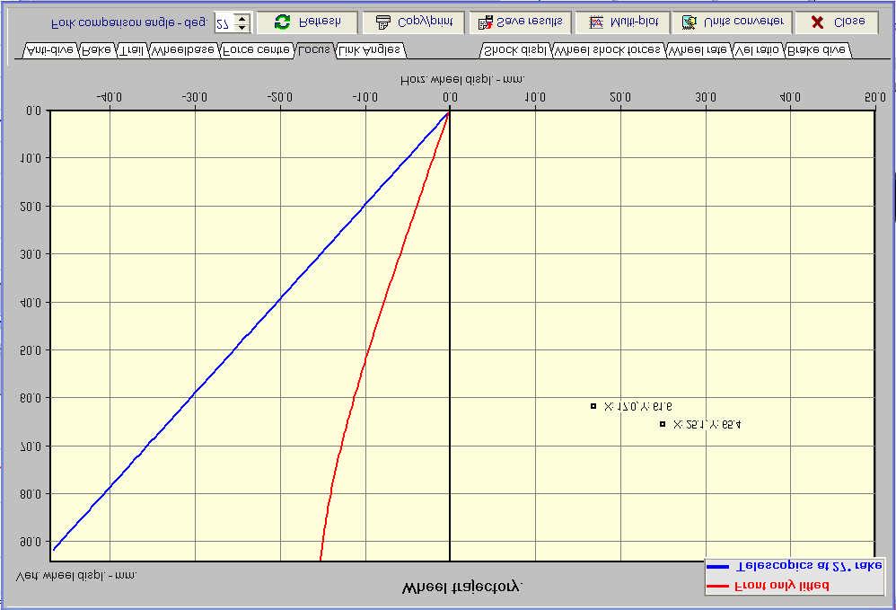
16 14 Example results plots There are several sets of calculated parameters pre-defined and plotted: anti-dive percentage, rake angle, trail and the trajectory of the wheel axle. The first three are plotted for the two extremes of rear wheel position and the area between the two curves defines the range of possible values for a particular parameter. The wheel trajectory plot also shows the wheel path that would occur with telescopic forks at a specified rake angle, this is just for reference. There are some special features available when the mouse pointer passes over a graph area. Cross-hairs appear automatically showing the X-Y values. Marking points. To mark a point, just click and release without moving the mouse. This will mark a point on a graph and show the X-Y parameter values. Line drawing. To draw a line, click and hold at the start and release at the end. The slope of the line will be calculated and displayed. Changing graph pages will remove the marks and lines, as will clicking the Refresh button.. The graph data can be saved in numeric form to a file, which can be later be used in the multi-plotting feature to compare multiple cases. The graph window can be saved to the clipboard and subsequently pasted into other software for creating reports etc. The following are typical results graphs:

17 15

18 16


19 17

20 18
21 Examples of data entry. Foale/Parker/GTS system. 19
22 20 Hossack/BMW duolever design
 or caliper mounting plate.")
23 21 Example of Leading Link forks Note that the two upright dimensions are equal and refer to the radius from the wheel axis to the mounting point for the torque arm on a floating back plate (for drum brakes) or caliper mounting plate. In the case that the back plate is fixed to a single arm, such as the leading link Earles style forks on the 1960s BMWs, you can model this design by making the rear pivots of the front (lower) swing arm and the torque arm (upper) concentric. For example using the swing arm dimensions from the example below, make X2 = 0, Y2 = Y1 = 280. L2 is relatively unimportant but it would be safe to make it equal to L1. The upright lengths can be any size greater than zero and less than L2. I use a value of 1. For any head stock mounted forks, the Head Stock box must be ticked and the values for rake angle and wheel offset need to be entered. See the later example. Trailing link forks Enter the data exactly the same as for the LL type with appropriate coordinates except use a negative value for the value of L1, the main link. The negative value signals the software that both links are trailing.
24 22 Here is the shock data that goes with the leading link fork example above.

25 An example of the data for Earles forks 23

26 24 Appendix This appendix describes in detail the use of the other software features. Use this if you have the Whole bike software loaded on the same computer. It will give you access to previously saved rear suspension data. Select the required file from the list as follows. You will see a graph and information about the data which helps decide if it is the file that you want. This will be used in the braking dive calculations which will also plot the rear suspension movement under braking as shown below. If the rear suspension data is not imported then the calculations will be done with the rear suspension set at full extension.

27 25 This is the results plot of the dive calculations including the displacement of the rear suspension under the influence of front wheel braking only. The lower blue line represents the actual dive to be expected and takes into account the anti- pro-dive characteristics of the design being analysed. The other lower lines are purely for comparative purposes. The red line shows the dive that would occur if dive was only dependent on load transfer alone. This would be the equivalent of a zero anti-dive percentage. The green line shows the dive to be expected from telescopic forks set to an angle specified by the number at the lower left. The calculations for the 0% anti-dive case and the telescopic case use the same effective vertical wheel rate as the actual case in blue. Note that three graphs end at slightly different braking decelerations. Each case stops at the deceleration that would cause the rear wheel to lift off the ground. These thresholds are determined by how the CG height and wheelbase vary with deceleration. It can be seen that the case with the telescopic forks reaches the threshold at lower decelerations, this may seem odd as the greater dive reduces the CG height more. This is true but that effect is overwhelmed by the amount that the wheelbase is shortened from the front due to the relatively large rearward component of the fork s displacement. As can be seen, the response of the rear suspension is less affected by the characteristics of the front. Only the actual case (the blue graph) is saved for viewing in the multi-plot feature. To create plots similar to the above it will be necessary to set the Gbrake parameter as the X-axis and the WheelDis as the Y-axis. For other saved parameters it would be usual to set WheelDis (Front wheel displacement) as the X-axis.

28 26 This is a simple tool to perform rake and trail calculations. Enter data into any three of the four data entry boxes, click on Calculate and it will calculate the fourth parameter. For example, if you know the required rake and trail values and wheel size then it will calculate the required offset necessary to give those values.

29 27 This is a wheel polar moment of inertia calculator. The wheel moments of inertia are used in the calculation of the anti-dive characteristics. This calculator is really two in one. It can calculate the moments of inertia for two different methods of physical measurements. The accuracy of the MoI values do not have a large effect on the anti-squat values, they are just a refinement to the calculations not a major part. In many cases the MoI values will not be available, if you do not have this information, use the value 1, which loads default values into the calculations based on typical wheels according to their weight. These default values will normally be sufficient. It is not difficult to measure the actual moments of inertia. There are many different ways of doing this depending on the facilities available, but these calculators do the hard work for two simple methods of measurement. They can be described as: 1. Swinging pendulum 2. Pulley and weight Swinging pendulum
, the wheel can be supported by the bar just under the rim section.")

30 28 The following photos show how the wheel needs to be mounted off-centre such that it can swing from side to side about an axis defined by the supporting bar. In cases where there is no convenient symmetrical supporting locations (rear wheels and single disc fronts), the wheel can be supported by the bar just under the rim section. The distance between the swing axis and the axle centre needs to be measured. The wheel should be slightly displaced to one side and allowed to swing back and forth like a pendulum. Measure the time required to complete a number of complete cycles, 20 for example to reduce the effect of timing errors. A swing amplitude of +/- 5 degrees is quite sufficient. This method has the advantage that only the minimum of equipment is needed to do the measurements. Apart from a stopwatch, weighing scales and a ruler or vernier calipers, a bar strong enough to support the wheel without excessive flex (10 mm. diameter is usually sufficient) and some means of supporting the bar horizontally is all that s necessary.
 needs to be made that can be attached to the wheel, concentric with its spin axis.")
31 29 Pulley and weight Probably the most accurate method of the two, but requires a little more preparation. A small pulley (about 100_mm diameter is ideal) needs to be made that can be attached to the wheel, concentric with its spin axis. Some thin cord or flexible cable is wound around the pulley and the free end attached to a known weight (2 kg. for example). Using this method the wheel can be supported with its own axle which must be mounted sufficiently high to allow the weight to fall the equivalent of two or more wheel revolutions. Using a pulley of 100 mm diameter, the weight will fall just over 0.3 metres for each revolution. The pulley should be a light as possible so that it contributes a minimum to the MoI of the wheel, although in most cases it will be a simple matter to calculate its own MoI and subtract from the overall value, but this is usually not necessary. Layout of pulley and wheel Sample pulley design.

32 30 The CG height is an important parameter needed for the analysis of motorcycle setup. There are various ways to measure this but most need facilities outside of those readily available. The simplest is to weigh each end of the machine when level and when lifted onto a block at one end. This calculator will then calculate the CG position. You can toggle the calculator depending on whether you raise the front or rear of the motorcycle. It is usually easier for the rider to raise the front end. A help window is built into the screen and warnings are given if input data is not mutually compatible.

33 31 Saving and loading data There are two types of data that can be saved in the software. Parametric (project data). Calculated results. The parametric data refers to the physical parameters of the motorcycle. For example, upright dimensions, wheel size etc. The calculated results are the characteristics of the system being analyzed such as anti-dive, wheel trajectory etc. Parametric (project data) The data is stored in the concept of a project. A project represents all the parametric data for a particular front suspension layout. Saving and loading parametric data is just a question of selecting a file name and confirming, as per usual software practice. Use the button on the principal screen Saving calculated results These can be saved by clicking on the button at the bottom of the results graphs. When saving both the parametric and calculated data it is suggested that you use a file name that will help identify the case when you return to it in the future.

34 32 Multi-plotting These access buttons are on both the principal screen and the results pages. They open a selection screen for choosing up to ten saved results files for comparative plotting. The window will initially open into the default file save directory. You can navigate to other directories if you saved the files elsewhere The second column will display a list of saved files. Click on those which you wish to compare (up to a maximum of ten), and they will appear in the plotting list across the bottom. There are buttons to remove files from this list or clear it altogether. Click on the Plot graphs button when you have listed the files of interest, three in this example.

35 33 The plotting window (shown next) has three areas. On the left are two lists of the parameters which can be plotted. The top one selects the parameter for the X axis, usually the Wheel displacement. The lower one selects the Y axis. The graphs will change dynamically as you select different plotting parameters. Along the bottom of the window, are some buttons with fairly obvious significance, except perhaps for the Scaling and offset. Occasionally it is useful to be able to scale or offset the data before plotting. The main area on this window is the plotting area which plots the chosen parameter from each of the selected files. On the plotting window, above, the area to the left shows that the wheel displacement has been chosen for the X axis and the anti-dive percentage, with the rear suspension extended for the Y axis. The three graphs show this parameter pair for the three files selected from the previous screen. This multi-file plotting feature is extremely useful for comparing different design iterations and is also very fast and easy to use.
SUMMARY OF STANDARD K&C TESTS AND REPORTED RESULTS
 Description of K&C Tests SUMMARY OF STANDARD K&C TESTS AND REPORTED RESULTS The Morse Measurements K&C test facility is the first of its kind to be independently operated and made publicly available in
ALIGNING A 2007 CADILLAC CTS-V
 ALIGNING A 2007 CADILLAC CTS-V I ll describe a four-wheel alignment of a 2007 Cadillac CTS-V in this document using homemade alignment tools. I described the tools in a previous document. The alignment
Simple Gears and Transmission
 Simple Gears and Transmission Simple Gears and Transmission page: of 4 How can transmissions be designed so that they provide the force, speed and direction required and how efficient will the design be?
SHAFT ALIGNMENT FORWARD
 Service Application Manual SAM Chapter 630-76 Section 24 SHAFT ALIGNMENT FORWARD One of the basic problems of any installation is aligning couplings or shafts. Therefore, this section will endeavor to
TO DIVE O R... Tony Foale January 1997
 TO DIVE O R... Tony Foale January 1997 Over the past couple of years the subject of anti-dive has received much attention, but there seems to be some divergence of opinion over the value of the Japanese
Roehrig Engineering, Inc.
 Roehrig Engineering, Inc. Home Contact Us Roehrig News New Products Products Software Downloads Technical Info Forums What Is a Shock Dynamometer? by Paul Haney, Sept. 9, 2004 Racers are beginning to realize
9 Locomotive Compensation
 Part 3 Section 9 Locomotive Compensation August 2008 9 Locomotive Compensation Introduction Traditionally, model locomotives have been built with a rigid chassis. Some builders looking for more realism
The Mark Ortiz Automotive
 August 2004 WELCOME Mark Ortiz Automotive is a chassis consulting service primarily serving oval track and road racers. This newsletter is a free service intended to benefit racers and enthusiasts by offering
Suspension Analyzer Full Vehicle Version
 Suspension Analyzer Full Vehicle Version Overview of Features The Full Vehicle version of Suspension Analyzer has several enhancements over the standard version, the most significant is analyzing various
Dynamics of Machines. Prof. Amitabha Ghosh. Department of Mechanical Engineering. Indian Institute of Technology, Kanpur. Module No.
 Dynamics of Machines Prof. Amitabha Ghosh Department of Mechanical Engineering Indian Institute of Technology, Kanpur Module No. # 04 Lecture No. # 03 In-Line Engine Balancing In the last session, you
DIY balancing. Tony Foale 2008
 DIY balancing. Tony Foale 2008 I hope that the main articles on the theory behind engine balance have removed the mystic which often surrounds this subject. In fact there is no reason why anyone, with
NEW DESIGN AND DEVELELOPMENT OF ESKIG MOTORCYCLE
 NEW DESIGN AND DEVELELOPMENT OF ESKIG MOTORCYCLE Eskinder Girma PG Student Department of Automobile Engineering, M.I.T Campus, Anna University, Chennai-44, India. Email: eskindergrm@gmail.com Mobile no:7299391869
V 2.0. Version 9 PC. Setup Guide. Revised:
 V 2.0 Version 9 PC Setup Guide Revised: 06-12-00 Digital 328 v2 and Cakewalk Version 9 PC Contents 1 Introduction 2 2 Configuring Cakewalk 4 3 328 Instrument Definition 6 4 328 Automation Setup 8 5 Automation
MicroGuard 586 Retrofit Rated Capacity Indicator System. Calibration and Testing for:
 GREER COMPANY Page 1 of 22 MicroGuard 586 Retrofit Rated Capacity Indicator System Machine Model Serial Number Tester Date Calibration and Testing for: GREER COMPANY Page 2 of 22 MicroGuard 586 Retrofit
The RCS-6V kit. Page of Contents. 1. This Book 1.1. Warning & safety What can I do with the RCS-kit? Tips 3
 The RCS-6V kit Page of Contents Page 1. This Book 1.1. Warning & safety 3 1.2. What can I do with the RCS-kit? 3 1.3. Tips 3 2. The principle of the system 2.1. How the load measurement system works 5
Good Winding Starts the First 5 Seconds Part 2 Drives Clarence Klassen, P.Eng.
 Good Winding Starts the First 5 Seconds Part 2 Drives Clarence Klassen, P.Eng. Abstract: This is the second part of the "Good Winding Starts" presentation. Here we discuss the drive system and its requirements
Appendix X New Features in v2.4 B
 Appendix X New Features in v2.4 B Version 2.4B adds several features, which we have grouped into these categories: New Suspension Types or Options The program now allows for solid front axles and for several
Design and Analysis of suspension system components
 Design and Analysis of suspension system components Manohar Gade 1, Rayees Shaikh 2, Deepak Bijamwar 3, Shubham Jambale 4, Vikram Kulkarni 5 1 Student, Department of Mechanical Engineering, D Y Patil college
SAE Mini BAJA: Suspension and Steering
 SAE Mini BAJA: Suspension and Steering By Zane Cross, Kyle Egan, Nick Garry, Trevor Hochhaus Team 11 Project Progress Submitted towards partial fulfillment of the requirements for Mechanical Engineering
KISSsys 03/2015 Instruction 010
 KISSsys 03/2015 Instruction 010 Positioning 07/04/2015 KISSsoft AG Rosengartenstrasse 4 8608 Bubikon Switzerland Tel: +41 55 254 20 50 Fax: +41 55 254 20 51 info@kisssoft.ag www.kisssoft.ag Contents 1.
Driven Damped Harmonic Oscillations
 Driven Damped Harmonic Oscillations Page 1 of 8 EQUIPMENT Driven Damped Harmonic Oscillations 2 Rotary Motion Sensors CI-6538 1 Mechanical Oscillator/Driver ME-8750 1 Chaos Accessory CI-6689A 1 Large Rod
SHOCK DYNAMOMETER: WHERE THE GRAPHS COME FROM
 SHOCK DYNAMOMETER: WHERE THE GRAPHS COME FROM Dampers are the hot race car component of the 90s. The two racing topics that were hot in the 80s, suspension geometry and data acquisition, have been absorbed
Using Advanced Limit Line Features
 Application Note Using Advanced Limit Line Features MS2717B, MS2718B, MS2719B, MS2723B, MS2724B, MS2034A, MS2036A, and MT8222A Economy Microwave Spectrum Analyzer, Spectrum Master, and BTS Master The limit
SPMM OUTLINE SPECIFICATION - SP20016 issue 2 WHAT IS THE SPMM 5000?
 SPMM 5000 OUTLINE SPECIFICATION - SP20016 issue 2 WHAT IS THE SPMM 5000? The Suspension Parameter Measuring Machine (SPMM) is designed to measure the quasi-static suspension characteristics that are important
Lab #3 - Slider-Crank Lab
 Lab #3 - Slider-Crank Lab Revised March 19, 2012 INTRODUCTION In this lab we look at the kinematics of some mechanisms which convert rotary motion into oscillating linear motion and vice-versa. In kinematics
SPMM OUTLINE SPECIFICATION - SP20016 issue 2 WHAT IS THE SPMM 5000?
 SPMM 5000 OUTLINE SPECIFICATION - SP20016 issue 2 WHAT IS THE SPMM 5000? The Suspension Parameter Measuring Machine (SPMM) is designed to measure the quasi-static suspension characteristics that are important
ECT Display Driver Installation for AP2 Module
 ECT Display Driver Installation for AP2 Module Overview The ECT Display Driver is a small module with a removable wire harness that mounts behind the driver's foot well cover. All wiring connections are
CurveMaker HD v1.0 2Ki Programmable Ignition programming software
 Contents CurveMaker HD v1.0 2Ki Programmable Ignition programming software Dynatek 164 S. Valencia St. Glendora, CA 91741 phone (626)963-1669 fax (626)963-7399 page 1) Installation 1 2) Overview 1 3) Programming
How To Build A Mini Chopper!
 How To Build A Mini Chopper! by Custom-Choppers-Guide.com Copyright All Rights Reserved. If you are new to such projects, it is strongly recommended that you do an assembly job, purchasing pre-constructed
Simple Gears and Transmission
 Simple Gears and Transmission Contents How can transmissions be designed so that they provide the force, speed and direction required and how efficient will the design be? Initial Problem Statement 2 Narrative
Technical Math 2 Lab 3: Garage Door Spring 2018
 Name: Name: Name: Name: As you may have determined the problem is a broken spring (clearly shown on the left in the picture below) which needs to be replaced. I. Garage Door Basics: Common residential
Analysis and control of vehicle steering wheel angular vibrations
 Analysis and control of vehicle steering wheel angular vibrations T. LANDREAU - V. GILLET Auto Chassis International Chassis Engineering Department Summary : The steering wheel vibration is analyzed through
Thanks for Ordering The Kawasaki KLX Adjustable Lowering Kit From
 www.scootworks.com Thanks for Ordering The Kawasaki KLX Adjustable Lowering Kit From READ THIS BEFORE UNPACKING YOUR KIT! This instruction booklet contains detailed steps for installing the rear suspension
RDS. For Windows TORSION SPRING CALCULATOR For ROLLING DOORS Version 4 REFERENCE MANUAL
 RDS For Windows TORSION SPRING CALCULATOR For ROLLING DOORS Version 4 REFERENCE MANUAL TABLE OF CONTENTS TABLE OF CONTENTS INTRODUCTION CREATING THE WORKING COPY INSTALLATION GETTING STARTED i iii iv v
FMVSS 126 Electronic Stability Test and CarSim
 Mechanical Simulation 912 North Main, Suite 210, Ann Arbor MI, 48104, USA Phone: 734 668-2930 Fax: 734 668-2877 Email: info@carsim.com Technical Memo www.carsim.com FMVSS 126 Electronic Stability Test
PowerSTAR PS-2024-D. Maximum Power Point Tracking Solar Regulator. w w w. r o c s o l i d. c o m. a u. Contents
 w w w. r o c s o l i d. c o m. a u PowerSTAR PS-2024-D Maximum Power Point Tracking Solar Regulator Contents 1 Quick Start Guide... 2 2 Specifications... 3 2.1 General Operation... 3 2.2 Absolute Maximum
Computer Power. Figure 1 Power-curves from Viper and Venom bottom left and right. (Source: D Quinlan)
") Introduction Computer Power The content of this article is, as you might guess, not about computer performance but rather how engine power can be predicted through the use of engine simulation tools. Little
Introduction Computer Power The content of this article is, as you might guess, not about computer performance but rather how engine power can be predicted through the use of engine simulation tools. Little
Charles Flynn s Permanent Magnet Motor.
 Charles Flynn s Permanent Magnet Motor. Patent US 5,455,474 dated 3rd October 1995 and shown in full in the Appendix, gives details of this interesting design. It says: This invention relates to a method
Model 2500 Horsepower Computer System User Manual
 Model 2500 Horsepower Computer System User Manual Manufacturered by: Ries Labs, Inc. 2275 Raven Road Farina, IL 62838 Phone: (618) 238-1400 email: admin@rieslabs.com Table of Contents Description ----------------------------------------------------------------
FRONTAL OFF SET COLLISION
 FRONTAL OFF SET COLLISION MARC1 SOLUTIONS Rudy Limpert Short Paper PCB2 2014 www.pcbrakeinc.com 1 1.0. Introduction A crash-test-on- paper is an analysis using the forward method where impact conditions
Mechanisms and Structures. Mechanical Systems. Levers. Basic Forces
 Mechanisms and Structures Mechanical Systems Levers Basic Forces Pupil Name Teacher Class Page 1 MECHANICAL SYSTEMS Our every day lives are made much easier by a variety of mechanical systems that help
PYRTE. Building The Front Axle, Fork and Steering
 PYRTE Building The Front Axle, Fork and Steering The front axle on this traction engine is a very simple affair, in that it is a rectangular steel rod, sat on edge, with a pivot in the centre, which is
Discussion Paper. Effect of Anti-Squat Adjustment in Solid Axle 4 Link Rear Suspension Systems
 Discussion Paper Effect of Anti-Squat Adjustment in Solid Axle 4 Link Rear Suspension Systems Example used is Commodore 1990 VG utility fitted with Whiteline KTA103 adjustable upper trailing arms. Prepared
Improving the gearshift feel in an SW20.
 Improving the gearshift feel in an SW20. Part one In 3 parts. The SW20 gearshift can be often be greatly improved by eliminating play in the shift linkages, and this article covers three areas that need
LG CORVETTE GT2 COIL OVERS
 LG CORVETTE GT2 COIL OVERS THE MOST POWERFUL HEADERS ON THE PLANET Brought to you by LG Motorsports 972-429-1963 Parts Inventory: 1. Assembled Front shock and spring 2. Assembled Rear shock and spring
Digital Hand Controller. Manual
 Digital Hand Controller Manual Authors: Dr.-Ing. T. Vaupel, D. Richter, M. Berger Translated by Wolfram Steinke Copyright Uhlenbrock Elektronik GmbH, Bottrop 3rd Edition March 2004 All Rights Reserved
2 Dynamics Track User s Guide: 06/10/2014
 2 Dynamics Track User s Guide: 06/10/2014 The cart and track. A cart with frictionless wheels rolls along a 2- m-long track. The cart can be thrown by clicking and dragging on the cart and releasing mid-throw.
Technical Report Lotus Elan Rear Suspension The Effect of Halfshaft Rubber Couplings. T. L. Duell. Prepared for The Elan Factory.
 Technical Report - 9 Lotus Elan Rear Suspension The Effect of Halfshaft Rubber Couplings by T. L. Duell Prepared for The Elan Factory May 24 Terry Duell consulting 19 Rylandes Drive, Gladstone Park Victoria
416 Air Shocks For Harley Davidson FLH/FLT 97-later*.
 Installation Instructions ATTENTION Statements in these instructions that are preceded by the following words are of special significance: W a r n i n g This means there is the possibility of injury to
CHASSIS DYNAMICS TABLE OF CONTENTS A. DRIVER / CREW CHIEF COMMUNICATION I. CREW CHIEF COMMUNICATION RESPONSIBILITIES
 CHASSIS DYNAMICS TABLE OF CONTENTS A. Driver / Crew Chief Communication... 1 B. Breaking Down the Corner... 3 C. Making the Most of the Corner Breakdown Feedback... 4 D. Common Feedback Traps... 4 E. Adjustment
Altec LMAP. (Load Moment and Area Protection) Telescopic Boom Cranes. Calibration
 Telescopic Boom Cranes. Calibration") Altec LMAP (Load Moment and Area Protection) Telescopic Boom Cranes Calibration Contents System Components...1 Anti-Two Block...1 Area Alarm...1 Boom Angle Sensor...1 Display...1 Extension Sensor...2 Function
Altec LMAP (Load Moment and Area Protection) Telescopic Boom Cranes Calibration Contents System Components...1 Anti-Two Block...1 Area Alarm...1 Boom Angle Sensor...1 Display...1 Extension Sensor...2 Function
Appendix 9: New Features in v3.5 B
 Appendix 9: New Features in v3.5 B Port Flow Analyzer has had many updates since this user manual was written for the original v3.0 for Windows. These include 3.0 A through v3.0 E, v3.5 and now v3.5 B.
Prop-Tech Vacuum Analyzer
 Electronic Carburettor / Injector Balancing Tool 1. WARNING THIS PRODUCT IS A PROFESSIONAL TOOL WHICH SHOULD ONLY BE OPERATED BY A COMPETENT TRAINED TECHNICIAN AND ONLY FOR THE PURPOSE WHICH IT WAS DESIGNED
:43 1/13 Victron & BYD B-Box
 2018-11-04 15:43 1/13 Victron & BYD B-Box Victron & BYD B-Box The combination of Victron products with BYD B-Box lithium batteries (2.5, 5.0, 7.5, 10.0 and 12.8 models) has been tested and certified by
UT Lift 1.2. Users Guide. Developed at: The University of Texas at Austin. Funded by the Texas Department of Transportation Project (0-5574)
") UT Lift 1.2 Users Guide Developed at: The University of Texas at Austin Funded by the Texas Department of Transportation Project (0-5574) Spreadsheet Developed by: Jason C. Stith, PhD Project Advisors:
UT Lift 1.2 Users Guide Developed at: The University of Texas at Austin Funded by the Texas Department of Transportation Project (0-5574) Spreadsheet Developed by: Jason C. Stith, PhD Project Advisors:
VBK 2596/12E/RSF. Thickness and Width Gauge for Strip and Profile. Operating- & Service Instructions. (with lateral guide rollers)
") Thickness and Width Gauge for Strip and Profile (with lateral guide rollers) VBK 2596/12E/RSF Operating- & Service Instructions erstellt am 5.2.1998 freigegeben am Bemerkungen Rev.01 Seiten:16 Name: Rietdorf
Thickness and Width Gauge for Strip and Profile (with lateral guide rollers) VBK 2596/12E/RSF Operating- & Service Instructions erstellt am 5.2.1998 freigegeben am Bemerkungen Rev.01 Seiten:16 Name: Rietdorf
The Basics of Balancing 101
 The Basics of Balancing 101 Gary K. Grim Bruce J. Mitchell Copyright 2014 Balance Technology Inc. Do not Distribute or Duplicate without the Authorized Written Consent of BTI (Balance Technology Inc.)
PVP Field Calibration and Accuracy of Torque Wrenches. Proceedings of ASME PVP ASME Pressure Vessel and Piping Conference PVP2011-
 Proceedings of ASME PVP2011 2011 ASME Pressure Vessel and Piping Conference Proceedings of the ASME 2011 Pressure Vessels July 17-21, & Piping 2011, Division Baltimore, Conference Maryland PVP2011 July
Jon Konings Former CEM Coordinator
 Jon Konings Former CEM Coordinator Not covering every detail of these QA topics. There is such a wide variation in the configuration of hardware out there, and I can t cover everything, so I will address
Theory of Machines II EngM323 Laboratory User's manual Version I
 Theory of Machines II EngM323 Laboratory User's manual Version I Table of Contents Experiment /Test No.(1)... 2 Experiment /Test No.(2)... 6 Experiment /Test No.(3)... 12 EngM323 Theory of Machines II
Parameters. Version 1.0 6/18/2008 1
 Warning: Remember to change your working directory before you begin this lesson. If you do not, Adams may not work correctly. Also remember to move everything you wish to keep from the working directory
Torque steer effects resulting from tyre aligning torque Effect of kinematics and elastokinematics
 P refa c e Tyres of suspension and drive 1.1 General characteristics of wheel suspensions 1.2 Independent wheel suspensions- general 1.2.1 Requirements 1.2.2 Double wishbone suspensions 1.2.3 McPherson
How to Build with the Mindstorm Kit
 How to Build with the Mindstorm Kit There are many resources available Constructopedias Example Robots YouTube Etc. The best way to learn, is to do Remember rule #1: don't be afraid to fail New Rule: don't
Dealer4 Maintenance, Adjusting and Cleaning Manual ver: 1.0
 Dealer4 Maintenance, Adjusting and Cleaning Manual ver: 1.0 Version information: Ver 1.0: First issue : 14/04/2008 - use word Board instead of Card Box - combine with Delaer4 Adjusting Manual 1V0 1 1 Dealer4
Laboratory Exercise 12 THERMAL EFFICIENCY
 Laboratory Exercise 12 THERMAL EFFICIENCY In part A of this experiment you will be calculating the actual efficiency of an engine and comparing the values to the Carnot efficiency (the maximum efficiency
CHAPTER 6 GEARS CHAPTER LEARNING OBJECTIVES
 CHAPTER 6 GEARS CHAPTER LEARNING OBJECTIVES Upon completion of this chapter, you should be able to do the following: Compare the types of gears and their advantages. Did you ever take a clock apart to
ISO 8855 INTERNATIONAL STANDARD. Road vehicles Vehicle dynamics and road-holding ability Vocabulary
 INTERNATIONAL STANDARD ISO 8855 Second edition 2011-12-15 Road vehicles Vehicle dynamics and road-holding ability Vocabulary Véhicules routiers Dynamique des véhicules et tenue de route Vocabulaire Reference
Basic Wheel Alignment Techniques
 Basic Wheel Alignment Techniques MASTERING THE BASICS: Modern steering and suspension systems are great examples of solid geometry at work. Wheel alignment integrates all the factors of steering and suspension
Converting a Series Land Rover to front wheel disc brakes using the kit made by Torrel Industries Ltd,
 Converting a Series Land Rover to front wheel disc brakes using the kit made by Torrel Industries Ltd, Torrel Industries ltd Series Land Rover front brake conversion kit: Difficulty - Low Except for one
AR2000 Rheometer: Instructions
 AR2000 Rheometer: Instructions Instrument Setup Note: The order in which the things are powered on is very important! 1. Check to make sure the Smart Swap cable is connected to the machine. 2. Make sure
HUSQVARNA SMR449/SMR511 A NEW BREED
 HUSQVARNA SMR449/SMR511 A NEW BREED Husqvarna has always been the star of the supermotard world. Husqvarna's numerous successes in this sport are accompanied by the commercial success obtained with innovative
Analysis and evaluation of a tyre model through test data obtained using the IMMa tyre test bench
 Vehicle System Dynamics Vol. 43, Supplement, 2005, 241 252 Analysis and evaluation of a tyre model through test data obtained using the IMMa tyre test bench A. ORTIZ*, J.A. CABRERA, J. CASTILLO and A.
SAE Mini BAJA: Suspension and Steering
 SAE Mini BAJA: Suspension and Steering By Zane Cross, Kyle Egan, Nick Garry, Trevor Hochhaus Team 11 Progress Report Submitted towards partial fulfillment of the requirements for Mechanical Engineering
Dynamic Analysis of Double Wishbone and Double Wishbone with S Link + Toe Link
 RESEARCH ARTICLE OPEN ACCESS Dynamic Analysis of Double Wishbone and Double Wishbone with S Link + Toe Link Rajkumar Kewat, Anil Kumar Kundu,Kuldeep Kumar,Rohit Lather, Mohit Tomar RJIT, B.S.F ACADEMY
SIX-BAR STEERING MECHANISM
 SIX-BAR STEERING MECHANISM Shrey Lende 1 1 UG Student, Department of Mech, G.H Raisoni College of Engineering, Nagpur, RTMN University ABSTRACT In this paper a steering system is designed for a Low weight
OVERSIZED DERAILLEUR PULLEY EFFICIENCY TEST
 OVERSIZED DERAILLEUR PULLEY EFFICIENCY TEST SUMMARY 0.49 watts efficiency difference was measured between a 10T-10T pulley combination and a 15T-15T pulley combination, with chain tension and bearing variables
BigStuff3 - GEN3. 1st Gear Spark Retard with Spark Retard Traction Control System (SR 2 ) Rev
 Rev") BigStuff3 - GEN3 1st Gear Spark Retard with Spark Retard Traction Control System (SR 2 ) 12-09 System Description 1st Gear Spark Retard with Spark Retard Traction Control System (SR 2 ) - SR 2 uses two
BigStuff3 - GEN3 1st Gear Spark Retard with Spark Retard Traction Control System (SR 2 ) 12-09 System Description 1st Gear Spark Retard with Spark Retard Traction Control System (SR 2 ) - SR 2 uses two
Chapter 7: DC Motors and Transmissions. 7.1: Basic Definitions and Concepts
 Chapter 7: DC Motors and Transmissions Electric motors are one of the most common types of actuators found in robotics. Using them effectively will allow your robot to take action based on the direction
1 Summary PROPORTIONAL RESPONSE TECHNICAL SUMMARY. Contents
 HABIT WHITE PAPER PROPORTIONAL RESPONSE TECHNICAL SUMMARY Contents 1 Summary 1 2 Suspension for Mountain Bikes 2 3 Proportional Response 10 4 Experimental Validation of Suspension Response 12 5 Size Specific
Learning to Set-Up Your Warrior Drive Belt Arizona Warrior (Rev4) BEFORE GETTING STARTED
 BEFORE GETTING STARTED") BEFORE GETTING STARTED 1. A noise one guy calls 'howling' is the same noise another guy calls 'squealing' so unless you are both hearing the noise with your own ears its better to not assume a drive belt
BEFORE GETTING STARTED 1. A noise one guy calls 'howling' is the same noise another guy calls 'squealing' so unless you are both hearing the noise with your own ears its better to not assume a drive belt
Extracting Tire Model Parameters From Test Data
 WP# 2001-4 Extracting Tire Model Parameters From Test Data Wesley D. Grimes, P.E. Eric Hunter Collision Engineering Associates, Inc ABSTRACT Computer models used to study crashes require data describing
B.TECH III Year I Semester (R09) Regular & Supplementary Examinations November 2012 DYNAMICS OF MACHINERY
 Regular & Supplementary Examinations November 2012 DYNAMICS OF MACHINERY") 1 B.TECH III Year I Semester (R09) Regular & Supplementary Examinations November 2012 DYNAMICS OF MACHINERY (Mechanical Engineering) Time: 3 hours Max. Marks: 70 Answer any FIVE questions All questions
1 B.TECH III Year I Semester (R09) Regular & Supplementary Examinations November 2012 DYNAMICS OF MACHINERY (Mechanical Engineering) Time: 3 hours Max. Marks: 70 Answer any FIVE questions All questions
1.0 SOFTWARE GRIPONE PRO 2
 1.0 SOFTWARE GRIPONE PRO 2 The user can manage the ECU GRIPONE PRO 2 by the software GRIPONE PRO 2. This software is available for Windows XP and Windows 7 OS. By the software the user can manage all the
Introducing the OMAX Generation 4 cutting model
 Introducing the OMAX Generation 4 cutting model 8/11/2014 It is strongly recommend that OMAX machine owners and operators read this document in its entirety in order to fully understand and best take advantage
2011+ Adjustable Tie-rod Ends (Mm5TR-2)
") 3430 Sacramento Dr., Unit D San Luis Obispo, CA 93401 Telephone: 805/544-8748 Fax: 805/544-8645 www.maximummotorsports.com 2011+ Adjustable Tie-rod Ends (Mm5TR-2) Instructions 1. Set the parking brake
3430 Sacramento Dr., Unit D San Luis Obispo, CA 93401 Telephone: 805/544-8748 Fax: 805/544-8645 www.maximummotorsports.com 2011+ Adjustable Tie-rod Ends (Mm5TR-2) Instructions 1. Set the parking brake
Learning Objectives:
 Topic 5.5 High Power Switching Systems Learning Objectives: At the end of this topic you will be able to; recall the conditions under which a thyristor conducts; explain the significance of the following
Cane Creek Double Barrel Instructions
 Cane Creek Double Barrel Instructions Congratulations on your purchase of the Cane Creek Double Barrel rear shock. Developed in partnership with Öhlins Racing, the Double Barrel brings revolutionary suspension
CurveMaker DFS v2.0 Dyna FS Ignition Programming Software
 CurveMaker DFS v2.0 Dyna FS Ignition Programming Software Contents Dynatek 164 S. Valencia St. Glendora, CA 91741 phone (626)963-1669 fax (626)963-7399 page 1) Installation 1 2) Overview 1 3) Introduction
Door panel removal F07 5 GT
 Things needed Decent plastic trim removal tools Torx 30 Spare door clips 07147145753 I got away with a set of 5 but if I did it again I d be cautious and get 10. From prior experience if they are damaged
Pearls from Martin J. King Quarter Wave Design
 Pearls from Martin J. King Quarter Wave Design An introduction by Bjorn Johannesen, Denmark. September the 1 st 2005. The first time you visit http://www.quarter-wave.com/, you might get overwhelmed by
Computerscales DX Model Operating Instructions (Also applies to models 72632, 72635, 72636)
") 16892 146 th St SE, Monroe, WA 98272 (360) 453-2030 Computerscales DX Model 72634 Operating Instructions (Also applies to models 72632, 72635, 72636) QUICK START INSTRUCTIONS: 1) Set up pads alongside
16892 146 th St SE, Monroe, WA 98272 (360) 453-2030 Computerscales DX Model 72634 Operating Instructions (Also applies to models 72632, 72635, 72636) QUICK START INSTRUCTIONS: 1) Set up pads alongside
IR_FAQ_7 09. Idleright Fact Sheet:
 Idleright Fact Sheet: 1. Q: What is the Idleright Fuel Management System? A: The Idleright is a purpose-built fuel management system designed to allow emergency vehicles to be parked with warning lights
Heat Engines Lab 12 SAFETY
 HB 1-05-09 Heat Engines 1 Lab 12 1 i Heat Engines Lab 12 Equipment SWS, 600 ml pyrex beaker with handle for ice water, 350 ml pyrex beaker with handle for boiling water, 11x14x3 in tray, pressure sensor,
Fourth Grade. Multiplication Review. Slide 1 / 146 Slide 2 / 146. Slide 3 / 146. Slide 4 / 146. Slide 5 / 146. Slide 6 / 146
 Slide 1 / 146 Slide 2 / 146 Fourth Grade Multiplication and Division Relationship 2015-11-23 www.njctl.org Multiplication Review Slide 3 / 146 Table of Contents Properties of Multiplication Factors Prime
Fiat - Argentina - Wheel Aligner / Headlamp Aimer #16435
 2017 iat - Argentina - Wheel Aligner / Headlamp Aimer #16435 Wheel Aligner / Headlamp Aimer Operation & Maintenance Manual Calibration / Testing ori Automation Version 1.2 4/21/2017 iat - Argentina - Wheel
Introduction: Supplied to 360 Test Labs... Battery packs as follows:
 2007 Introduction: 360 Test Labs has been retained to measure the lifetime of four different types of battery packs when connected to a typical LCD Point-Of-Purchase display (e.g., 5.5 with cycling LED
Armature Reaction and Saturation Effect
 Exercise 3-1 Armature Reaction and Saturation Effect EXERCISE OBJECTIVE When you have completed this exercise, you will be able to demonstrate some of the effects of armature reaction and saturation in
Fourth Grade. Slide 1 / 146. Slide 2 / 146. Slide 3 / 146. Multiplication and Division Relationship. Table of Contents. Multiplication Review
 Slide 1 / 146 Slide 2 / 146 Fourth Grade Multiplication and Division Relationship 2015-11-23 www.njctl.org Table of Contents Slide 3 / 146 Click on a topic to go to that section. Multiplication Review
Introduction. Kinematics and Dynamics of Machines. Involute profile. 7. Gears
 Introduction The kinematic function of gears is to transfer rotational motion from one shaft to another Kinematics and Dynamics of Machines 7. Gears Since these shafts may be parallel, perpendicular, or
MiR Hook. Technical Documentation
 MiR Hook Technical Documentation Version 1.7 Software release 1.7 Release date: 10.11.2016 Table of contents 1 Introduction...3 2 The MiR Hook hardware...3 3 Trolley specifications...4 4 Space requirements...5