ECT Display Driver Installation for AP2 Module
|
|
|
- Edmund Hudson
- 5 years ago
- Views:
Transcription
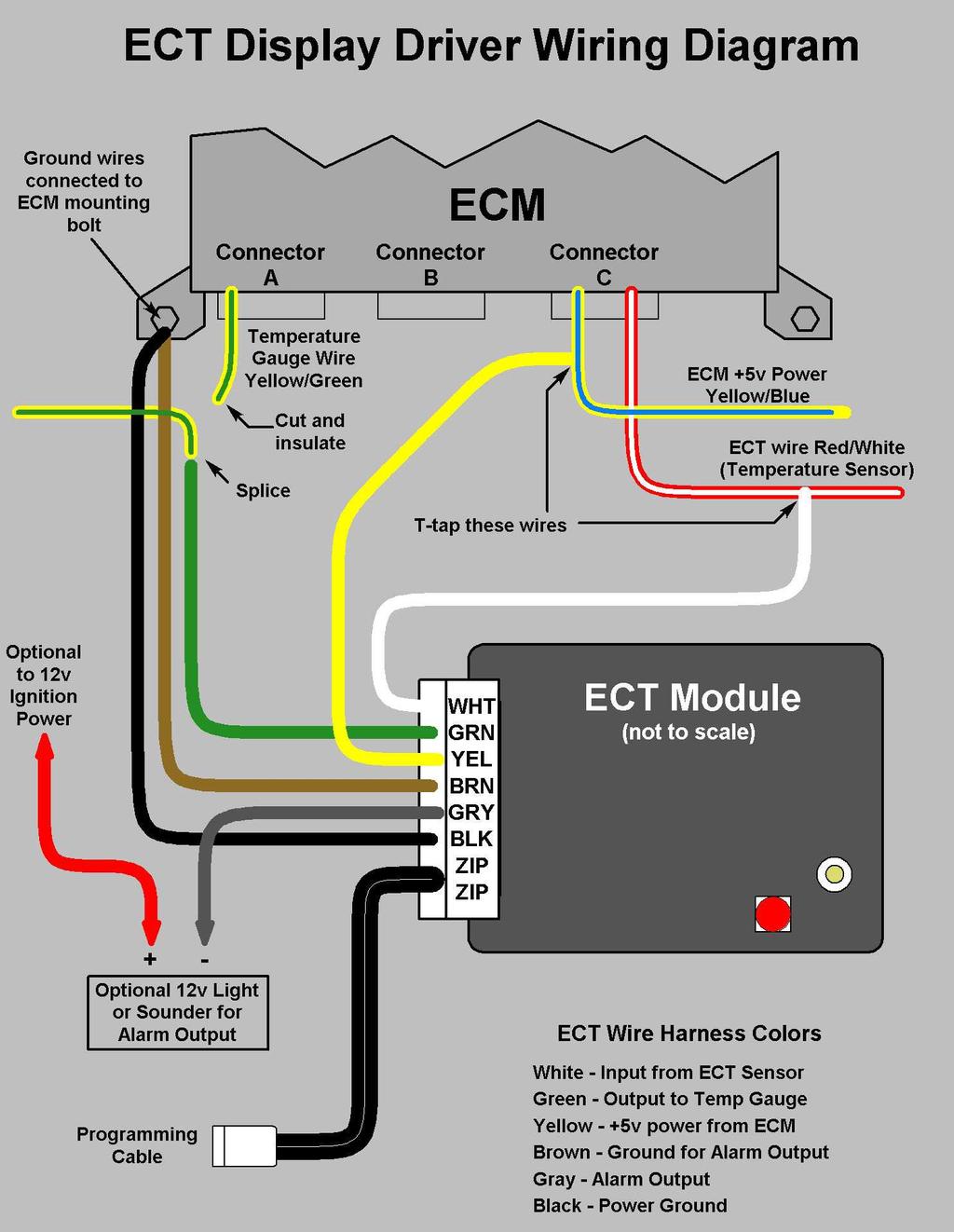
1 ECT Display Driver Installation for AP2 Module Overview The ECT Display Driver is a small module with a removable wire harness that mounts behind the driver's foot well cover. All wiring connections are near the ECM and only 4 wires are needed for basic operation: +5v power from the ECM (T-tap) Ground available at ECM mounting bolt ECT sensor wire (T-tap at ECM) Dash temperature gauge wire (must cut at ECM) If you want to use the optional Alarm Output feature 3 more wires are needed: Ground (must be run separate from the module's power ground) Module output (negative) to your alarm device (sounder or indicator light, not included) +12v ignition or accessory power wired directly to your alarm device Installation Details: refer to the photos and wiring diagram at the end of this manual 1. Remove the driver s side doorsill trim and the driver s foot well trim. (if you don t know how to do this you probably shouldn t be doing this modification) 2. Locate the connectors and wires you will be using, see photos at the end of this manual. a. Temperature gauge wire (Yellow/Green) Easily seen at the top left of connector A on the ECM. b. Power wire for +5v (Yellow/Blue) This is on the rear-most row of wires on connector C, in the middle section of the connector. You will have to remove connector C from the ECM to locate this wire c. ECT Sensor wire (Red/White) This is also on the rear-most row of wires on connector C, in the middle section of the connector. 3. Attach crimp connectors to the ECM wires as detailed below. a. Using a pair of pliers, clamp one of the red T-taps around the Yellow/Blue wire in connector C, making sure the wire goes into the metal slot of the T-tap. If you have strong fingers you can squeeze the T-tap on the wire to hold it temporarily, then use the pliers to clamp it shut. Or, you can position the T-tap in the pliers jaw, then clamp it on the wire. b. Crimp another T-tap around the Red/White wire in connector C. c. Now cut the Yellow/Green wire a few inches away from the ECM and strip about ¼ of insulation from each end. d. Using a crimp tool, crimp a female spade connector on the end of the Yellow/Green wire that comes from the ECM. e. Next crimp a male spade connector on the other end of the Yellow/Green wire (the end going into the wire bundle). f. Note that the ends of the Yellow/Green wire have opposite connectors. If you ever have to remove the ECT Module you simply plug these connectors together and the temperature gauge will work like normal.
2 4. Attach crimp connectors to the ECT wire harness. a. One ring terminal (each) for the Black and Brown wires. b. The male spades crimp on the White and Yellow wires. c. The female spade crimps on the Green wire. 5. Connect the ECT harness wires to the car wiring. a. Plug the ECT Yellow wire into the T-tap on the Yellow/Blue wire from connector C. This is +5v power. b. Connect the ECT White wire into the T-tap on the Red/White wire from connector C. This is the ECT sensor wire. c. Connect ECT Green wire to the Yellow/Green wire that s going into the wire bundle. This is the output to the dash temperature gauge. d. Leave the Yellow/Green wire going into ECM connector A hanging loose, it s not needed. e. Connect the Black and Brown wires to a good ground, either at the ECM mounting bolts or the hood release latch. Testing: Turn the ignition to ON and observe the LED on the module to make sure it is blinking. Blink rates will vary from once every 2 seconds (engine cold) to about 5 blinks a second (engine overheated), with normal coolant temperatures causing about 1 to 1.5 blinks per second. If the LED does not blink then the module is either bad or is not receiving power, so check the +5v (Yellow wire) and power ground (Black wire) connections. The Black wire MUST be grounded. Grounding only the Brown wire will NOT provide a power ground to the module. Also, accidentally connecting the Yellow wire to a +12v source instead of +5v ECM power will instantly and permanently damage the module. If the car is already warmed up you should observe between 5 and 10 segments illuminated on the dash temperature gauge. If there is no gauge activity after the ignition is on for 20 seconds there is likely a problem with the module s Green wire connection to the temperature gauge wire. If the engine is not warm, go ahead and start it and operate the vehicle long enough to warm it up. You should observe the gauge respond to increasing coolant temperature, and if you have the default programming you should see 10 segments (exactly half the gauge) illuminated when the engine is fully warm.

3 ECT Display Driver Operational Notes Notes on the stock temperature gauge The stock temperature gauge uses the temperature settings shown on the left and the default programming of the ECT module will re-calibrate the gauge as shown on the right. Most owners are used to seeing 8 segments all the time, which is not surprising once you know that the 8 th segment covers a temperature range from 178 to 22 5 F. I can only guess that Honda did this to provide consistent gauge readings and reduce questions about gauge fluctuations. The gauge has considerable averaging built into it, which results in delayed gauge response. In my testing I ve seen a 3-second delay between when the coolant temperature sensor voltage changes and the gauge responds. If I suddenly change the input voltage enough to cause 2 additional segments to light up, it takes about 3 seconds for the next segment to light and an additional 3 seconds for the second segment. This delay occurs during falling temperatures also. The only time there is no delay in the gauge response is when you first turn the ignition ON. Honda must have specifically designed the system to check the coolant temperature and immediately display the correct reading on the gauge. That way you don t get into a warm car and think the engine is still cold because of a slow-responding gauge. Diagnostic Mode Diagnostic Mode can be helpful when trying to verify programming changes you have made or if you are using an after-market engine management system. Diagnostic Mode is activated by pressing the tiny push button on the module until the LED gives a one-second flash and will remain active until reset by turning the ignition OFF. Diagnostic Mode causes the module LED and Alarm Output to activate each time the coolant sensor voltage crosses one of the set points. The LED and Alarm Output blink out the number of gauge segments that should be lit. In addition, it blinks fast for a rising temperature and slow for a falling temperature. This is easier to understand with an example: Assume you have activated Diagnostic Mode and the car is warming up and reaches the set point for the third segment on the gauge. As soon as that threshold is reached the LED will flash 3 short blinks, indicating the temperature is rising and 3 segments should be displayed on
4 the gauge (after the 3-4 second delay). If the temperature cools down below the 3 segment threshold you will see 2 long blinks, indicating a falling temperature and after a few seconds you will see a new gauge reading of 2 segments. Diagnostic mode works best if a small piezo sounder is connected to the Alarm Output. With the AP2 version of the ECT module Diagnostic Mode can be difficult to use because of the number of gauge segments. You will need to be patient and carefully count the LED blinks or beeper chirps to know which gauge segment should be lit. If you do any testing in Diagnostic Mode and monitor the ECT voltage with a meter you may notice the gauge transitions differ from your set points by 1 to 3 millivolts. This is usually caused by the ECM voltage (the 5v supply for the module) being slightly different than exactly 5 volts. These errors in supply voltage are somewhat self-corrected by the module since the voltage reference used for the A-D converter is tied to the 5v supply, but it's not perfect. If you find the self-correction is not accurate enough, just tweak your programmed set points slightly until the transitions are exactly where you want them. Alarm Output The Alarm Output feature can be used to activate a light or sounder when the programmed sensor voltage is reached. I can think of a few uses for this: 1. Overheat warning to get your immediate attention in case you don t check the gauge frequently. 2. OK to VTEC indicator if you decide to change the temperature ranges you may lose the 160 F gauge segment, so you could use a separat e indicator to tell you when the engine was sufficiently warmed up for VTEC operation. You could even use the output to activate a relay to disconnect the VTEC solenoid, making VTEC impossible when the engine is cold. The Alarm Output provides a ground when active so you will need to run a separate +12v wire to your light or sounder and use the module to provide the ground. It can provide up to ½ amp of current, but be careful because there is no internal fuse. Connecting it to a device that draws more than an amp will damage the module, so if you need more current you will need to install a relay. The output will rapidly pulse 4 or 5 times when it first activates, then it stays on until the ECT voltage rises above the alarm threshold, indicating the temperature has dropped. If the temperature goes up again, the pulsing/steady cycle will repeat. You may wonder why there is a separate ground wire (Brown) for the Alarm Output. The module measures the ECT sensor voltage relative to ground. That means it looks at the voltage difference between the White wire and the Black wire where they connect to the module. Any voltage drop on the Black wire between the ground connection and the module will cause an erroneous reading. Since the module draws very little current(<10ma) the normal operating voltage drop is insignificant. But if ½ amp of alarm current were to pass through the Black wire the voltage drop would be large enough to cause errors in the ECT voltage measurement, and a corresponding error in the gauge output. We can t have that, so a separate ground is used for the Alarm Output circuit.
5 The Alarm Output software has some hysteresis built in so that you don't get "on-off-on-off" cycling of the output. That could be annoying if you connect a sounder to the module and the ECT voltage is exactly at the alarm transition point. Minor fluctuations in the sensor voltage could cause the Alarm to cycle ON and OFF rapidly. To prevent this I have programmed the module to go into alarm exactly at your programmed set point, but not to turn off unless the voltage rises at least 5mv (.005volts) above the threshold. Bear that in mind if you do any Diagnostic Mode testing with a voltmeter on the ECT input. Tables of coolant temperatures and corresponding ECT voltages Use these voltage values if you decide to change the default programming of your ECT module. See the programming instructions following these charts. You should use the Coolant temp column as your temperature because it is the most accurate. The OBD Temp is the temperature indicated by my car s OBDII system, which in most cases was 2-5 degrees high. I only included it here for reference in case any of you are using an OBDII tool. Every 5 degrees F Every 2 degrees F Every 2 degrees F Coolant temp Stock AEM OBD Temp Coolant temp Stock AEM OBD Temp Coolant temp Stock AEM OBD Temp

6 ECT Display Driver - Programming Overview The ECT Display Driver comes with default programming as described in the previous page but can be re-programmed for custom temperature ranges with the use of the included programming cable and a laptop equipped with a serial port and communications software such as HyperTerminal. Here are the basic steps: Set up HyperTerminal for 9600, 8,N,1 (9600 baud, 8 data bits, no parity, 1 stop bit) With the ignition ON, connect the programming cable between the laptop and the module Transmit a text file containing the new programming values to the module Verify the module has accepted the programming Detailed steps for programming: 1. Copy the HyperTerminal session file and sample data files from my web site: a. I would suggest using the default data files for your first programming attempt. Once you do a successful download and prove your laptop serial port is working, then edit the data file and download your new set points. 2. Start HyperTerminal on your laptop by double-clicking the ECT on Comm1.ht file that you downloaded from my web site. 3. With the ignition ON, connect the programming cable from the laptop serial port to the ECT module. The module can only be programmed when powered up. 4. Click the connect icon in the tool bar. 5. On the tool bar click Transfer, then Send Text File a. Browse to where the data file is located and highlight the file. Do not double-click it at this time. You will transfer the file in the next step.
7 b. Observe the LED on the module as you hit the <Enter> key. 1. The LED should light during the file transfer ( 5-10 seconds) 2. The LED will go out as the new data is programmed into the module s EEPROM memory. 3. The LED will flash 2 slow one-second blinks to indicate the transfer and load were successful. 6. Unsuccessful downloads can be caused by: a. Invalid text file usually caused by missing brackets [ ] or deleting lines at the beginning of the file. Look for this if you do not get 2 slow blinks. b. Wrong voltage parameter used, (not 4 characters in length). Look for this type of error if the module gives 5 quick blinks after the download. That s it, the module is programmed and ready to operate. Editing the data file The data file is a simple text file that can be edited with any text editor, such as Notepad. I suggest you do not use Word or other word processing programs because they can leave invisible non-ascii characters in the file that may interfere with the download process or cause the module to operate in an unexpected manner. The data file uses actual ECT sensor voltage values to set the activation point for each gauge segment. By using voltage instead of temperature the module is more flexible and can work on both stock and after-market engine management systems. The value in the brackets [ ] defines the transition point between gauge segments. For example, the stock data file looks like this (partial): [1944] millivolts - 2nd segment lights at 110 degrees [1495] millivolts - 3rd segment lights at 130 degrees The first line indicates that the second gauge segment will light when the sensor voltage drops to 1944 millivolts (1.944 volts) and will go out if the voltage rises above 1944 millivolts. If the voltage continues to drop to 1495mv (or below) the third gauge segment will illuminate. Please note that the text after the brackets is a comment and has no effect on the module programming. It is only there to remind you what the settings mean. If you change the voltage values in the brackets for different temperature settings it s a good practice to edit the comment to indicate the temperature you are using for that value, but it s not required. Here are some rules for editing the text file: 1. Do not edit or delete any lines above the bracketed [ ] data values. 2. Data values must be enclosed in brackets [ ] and be exactly 4 characters long. s less than 100mv must use preceding zeros - 85mv should be entered as [0085]. 3. You are free to edit the comments after each data value, just keep it short. 4. The voltage values must always be in the specified segment order 2 nd segment, 3 rd segment, 4 th segment, etc, with the alarm set point last. 5. Feel free to add/edit/delete any of the text AFTER the section with the data values.

8 Photos to be used with Installation Instructions Photo 1 view of the ECM and the various connectors you will be using. C501 is only shown in case you decide to connect the optional Alarm Output to the seatbelt warning light as I have done in my car.


9 Photo 2 Close-up view of ECM connectors A and C Photo 3 Close-up of C501 and optional connection to seatbelt warning wire. I connected my alarm output to the seatbelt light it does a good job of getting my attention if it lights up.
10
Idle Timer Controller - A-ITC620-A Chevrolet Express/GMC Savana
 An ISO 9001:2008 Registered Company Idle Timer Controller - A-ITC620-A1 2009-2018 Chevrolet Express/GMC Savana Contact InterMotive for additional vehicle applications Introduction The A-ITC620-A1 is an
ITCEMS950 Idle Timer Controller - Engine Monitor Shutdown Isuzu NPR 6.0L Gasoline Engine
 Introduction An ISO 9001:2008 Registered Company ITCEMS950 Idle Timer Controller - Engine Monitor Shutdown 2014-2016 Isuzu NPR 6.0L Gasoline Engine Contact InterMotive for additional vehicle applications
Idle Timer Controller - A-ITC620-A Chevrolet Express/GMC Savana
 Introduction An ISO 9001:2015 Registered Company Idle Timer Controller - A-ITC620-A1 2009-2019 Chevrolet Express/GMC Savana Contact InterMotive for additional vehicle applications The A-ITC620-A1 is an
Idle Timer Controller - ITC515-A Ford Transit Contact InterMotive for additional vehicle applications
 An ISO 9001:2008 Registered Company Idle Timer Controller - ITC515-A 2015-2018 Ford Transit Contact InterMotive for additional vehicle applications Overview The ITC515-A system will shut off gas or diesel
Installation Tips for your Crimestopper/ProStart Remote Start system (add-on for GM vehicles) v1.02 updated 1/16/2013
 v1.02 updated 1/16/2013") Installation Tips for your Crimestopper/ProStart Remote Start system (add-on for GM vehicles) v1.02 updated 1/16/2013 Thank you for purchasing your remote start from MyPushcart.com - an industry leader
Installation Tips for your Crimestopper/ProStart Remote Start system (add-on for GM vehicles) v1.02 updated 1/16/2013 Thank you for purchasing your remote start from MyPushcart.com - an industry leader
An ISO 9001:2008 Registered Company
 An ISO 9001:2008 Registered Company Introduction Engine Monitor System 2009-2018 Ford E Series (EMS501-D) 2008-2010 Ford F250-550 6.2L, 6.8L (EMS506-D) 2011-2016 Ford F250-550 6.2L, 6.8L (EMS507-D) 2017
Idle Timer Controller - A-ITC520-A Ford E Series Ford F250 - F Ford F250 - F550 (*B-ITC520-A) F650/F750
 F650/F750") An ISO 9001:2008 Registered Company Idle Timer Controller - A-ITC520-A 2009-2018 Ford E Series 2008-2016 Ford F250 - F550 2017-2018 Ford F250 - F550 (*B-ITC520-A) 2016-2018 F650/F750 *Uses the Ford 24-Pin
An ISO 9001:2008 Registered Company Idle Timer Controller - A-ITC520-A 2009-2018 Ford E Series 2008-2016 Ford F250 - F550 2017-2018 Ford F250 - F550 (*B-ITC520-A) 2016-2018 F650/F750 *Uses the Ford 24-Pin
Idle Timer Controller - ITC Freightliner MT45 Contact InterMotive for additional vehicle applications
 An ISO 9001:2008 Registered Company System Operation Idle Timer Controller - ITC805 2013-2018 Freightliner MT45 Contact InterMotive for additional vehicle applications The ITC805 system shuts down idling
TIP SHEET T0937. Installation Tips For RS00/PS00 + ADS-TBSL-PL + SPDT
 Installation Tips For RS00/PS00 + ADS-TBSL-PL + SPDT TIP SHEET T0937 Thank you for purchasing your remote start from MyPushcart.com - an industry leader in providing remote starts to do-it-yourself installers
Installation Tips for your Add-on Remote Start (for GM vehicles with INTSL Install 2) v3.2 Updated 11/12/2012
 v3.2 Updated 11/12/2012") Installation Tips for your Add-on Remote Start (for GM vehicles with INTSL Install 2) v3.2 Updated 11/12/2012 Thank you for purchasing your remote start from MyPushcart.com - an industry leader in providing
Installation Tips for your Add-on Remote Start (for GM vehicles with INTSL Install 2) v3.2 Updated 11/12/2012 Thank you for purchasing your remote start from MyPushcart.com - an industry leader in providing
Installation Tips for your Remote Start system (for RS4LX>GMBP for GM vehicles)
") Installation Tips for your Remote Start system (for RS4LX>GMBP for GM vehicles) Thank you for purchasing your remote start from MyPushcart.com - an industry leader in providing remote starts to doit-yourself
Installation Tips for your Remote Start system (for RS4LX>GMBP for GM vehicles) Thank you for purchasing your remote start from MyPushcart.com - an industry leader in providing remote starts to doit-yourself
Installation Tips for RS4/RS7 + EVO-ALL (NIS 3.b)
") Installation Tips for RS4/RS7 + EVO-ALL (NIS 3.b) TIP SHEET T3092 + T3102 FOR: NISSAN ( 08-14 Frontier), ( 08-12 Pathfinder), & ( 08-12 Xterra) Thank you for purchasing your remote start from MyPushcart.com
Installation Tips for RS4/RS7 + EVO-ALL (NIS 3.b) TIP SHEET T3092 + T3102 FOR: NISSAN ( 08-14 Frontier), ( 08-12 Pathfinder), & ( 08-12 Xterra) Thank you for purchasing your remote start from MyPushcart.com
Installation Tips for RS4/RS7 + EVO-ALL (NIS 3.c) + 2 diodes
 + 2 diodes") Installation Tips for RS4/RS7 + EVO-ALL (NIS 3.c) + 2 diodes TIP SHEET T3093 + T3103 FOR: NISSAN ( 09-14 Cube), ( 11-14 Juke), & ( 07-11 Versa) automatic, regular key vehicles Thank you for purchasing
Installation Tips for RS4/RS7 + EVO-ALL (NIS 3.c) + 2 diodes TIP SHEET T3093 + T3103 FOR: NISSAN ( 09-14 Cube), ( 11-14 Juke), & ( 07-11 Versa) automatic, regular key vehicles Thank you for purchasing
Installation Tips for RS1 + EVO-RIDE + SPDT. *(reglar key, automatic transmission vehicles ONLY)*
*") Installation Tips for RS1 + EVO-RIDE + SPDT TIP SHEET T1235 *(reglar key, automatic transmission vehicles ONLY)* Thank you for purchasing your remote start from MyPushcart.com - an industry leader in providing
Installation Tips for RS1 + EVO-RIDE + SPDT TIP SHEET T1235 *(reglar key, automatic transmission vehicles ONLY)* Thank you for purchasing your remote start from MyPushcart.com - an industry leader in providing
TIP SHEET. Installation Tips for your RS IB-MUX / PKUMUX (D) + SPDT T1205 v1.2 4/3/14. 1 P a g e
 + SPDT T1205 v1.2 4/3/14. 1 P a g e") Installation Tips for your RS-150 + IB-MUX / PKUMUX (D) + SPDT T1205 v1.2 4/3/14 TIP SHEET Thank you for purchasing your remote start from MyPushcart.com - an industry leader in providing remote starts
Installation Tips for your RS-150 + IB-MUX / PKUMUX (D) + SPDT T1205 v1.2 4/3/14 TIP SHEET Thank you for purchasing your remote start from MyPushcart.com - an industry leader in providing remote starts
Read the entire installation manual. There are several safety tips there that you need to know before you start
 Installation Tips for RS4 + INTSL (2) TIP SHEET T0749 Buick Century: 2000-2005 Buick LeSabre: 2000-2005 Buick Park Avenue: 1999-2005 Buick Ranier: 2004-2007 Cadillac Escalade: 2003-2007 Chevrolet Avalanche:
Installation Tips for your Remote Start system (for Toyota Camry & Prius C, ) Crimestopper RS0+ EVO-ALL T3468 rev#1.
 Crimestopper RS0+ EVO-ALL T3468 rev#1.") Installation Tips for your Remote Start system (for Toyota Camry & Prius C, 2012-2014) Crimestopper RS0+ EVO-ALL T3468 rev#1.1 1/22/2015 Thank you for purchasing your remote start from MyPushcart.com -
Installation Tips for your Remote Start system (for Toyota Camry & Prius C, 2012-2014) Crimestopper RS0+ EVO-ALL T3468 rev#1.1 1/22/2015 Thank you for purchasing your remote start from MyPushcart.com -
TIP SHEET T2352, T3396. Installation Tips for RS1 + EVO-ALL 1-BUTTON REMOTE STARTER FOR: Acura RDX PUSH-TO-START / AUTOMATIC
 Installation Tips for RS1 + EVO-ALL 1-BUTTON REMOTE STARTER FOR: Acura RDX 2013-2015 PUSH-TO-START / AUTOMATIC TIP SHEET T2352, T3396 Thank you for purchasing your remote start from MyPushcart.com - an
Step 1 Wiring your remote start. Installation Tips for your Remote Start system (for GM vehicles) V3.3 revised 9/12/2013
 V3.3 revised 9/12/2013") Installation Tips for your Remote Start system (for GM vehicles) V3.3 revised 9/12/2013 Thank you for purchasing your remote start from MyPushcart.com - an industry leader in providing remote starts to
Installation Tips for your Remote Start system (for GM vehicles) V3.3 revised 9/12/2013 Thank you for purchasing your remote start from MyPushcart.com - an industry leader in providing remote starts to
Installation Tips for your RS-1 + Honda-SL3 (1.b) Remote starter Honda: ( FIT), ( Pilot), ( Ridgeline) Acura: ( MDX)
 Remote starter Honda: ( FIT), ( Pilot), ( Ridgeline) Acura: ( MDX)") Installation Tips for your RS-1 + Honda-SL3 (1.b) Remote starter Honda: ( 06-08 FIT), ( 05-08 Pilot), ( 06-13 Ridgeline) Acura: ( 03-06 MDX) TIP SHEET T0777 Thank you for purchasing your remote start from
Installation Tips for your RS-1 + Honda-SL3 (1.b) Remote starter Honda: ( 06-08 FIT), ( 05-08 Pilot), ( 06-13 Ridgeline) Acura: ( 03-06 MDX) TIP SHEET T0777 Thank you for purchasing your remote start from
Installation Tips - (Crimestopper RS1/RS2) & (Fortin EVO-ALL 5): *regular key & automatic transmission only*
 & (Fortin EVO-ALL 5): *regular key & automatic transmission only*") Installation Tips - (Crimestopper RS1/RS2) & (Fortin EVO-ALL 5): TIP SHEET T3385f, T3413f *regular key & automatic transmission only* Thank you for purchasing your remote start from MyPushcart.com - an
Installation Tips - (Crimestopper RS1/RS2) & (Fortin EVO-ALL 5): TIP SHEET T3385f, T3413f *regular key & automatic transmission only* Thank you for purchasing your remote start from MyPushcart.com - an
Installation Tips Crimestopper/ProStart Remote Start system + PLJX + DLRM + SPDT (for GM vehicles) T0760 v1.1 updated 2/5/14
 T0760 v1.1 updated 2/5/14") Installation Tips Crimestopper/ProStart Remote Start system + PLJX + DLRM + SPDT (for GM vehicles) T0760 v1.1 updated 2/5/14 Thank you for purchasing your remote start from MyPushcart.com - an industry
Installation Tips Crimestopper/ProStart Remote Start system + PLJX + DLRM + SPDT (for GM vehicles) T0760 v1.1 updated 2/5/14 Thank you for purchasing your remote start from MyPushcart.com - an industry
Installation Tips for your Crimestopper/ProStart Remote Start system (for GM vehicles) v1.01 updated 2/27/2012
 v1.01 updated 2/27/2012") Installation Tips for your Crimestopper/ProStart Remote Start system (for GM vehicles) v1.01 updated 2/27/2012 Thank you for purchasing your remote start from MyPushcart.com - an industry leader in providing
Installation Tips for your Crimestopper/ProStart Remote Start system (for GM vehicles) v1.01 updated 2/27/2012 Thank you for purchasing your remote start from MyPushcart.com - an industry leader in providing
Connecting the rear fog light on the A4 Jetta, while keeping the 5 Light Mod
 Connecting the rear fog light on the A4 Jetta, while keeping the 5 Light Mod DISCLAIMER: I'm human and make mistakes. If you spot one in this how to, tell me and I'll fix it This was done on my 99.5 Jetta.
Wired Real Time GPS Installation Instructions
 Wired Real Time GPS Installation Instructions This page intentionally left blank. TABLE OF CONTENTS 1. Introduction 2 2. Selecting the Mounting Location for the Device. 3 3. Mounting the Device 5 4. Optional
RS4/RS7 + + SPDT T0776,T0731
 TIP SHEET Installation Tips for your RS4/RS7 + Honda-SL3 (1.a) + SPDT T0776,T0731 Honda: ( 03-07 Accord),( 01-05 Civic),( 02-06 CRV),( 03-10 Element),( 05-10 Odyssey) Acura: ( 01-03 EL),( 02-06 RSX),(
RS4-7/PS4-7 + (2) + SPDT T3015, T3053
 + SPDT T3015, T3053") TIP SHEET Installation Tips for your RS4-7/PS4-7 + Honda-SL3 (2) + SPDT T3015, T3053 v1.3 4/25/14 Honda: ( 98-02 Accord), ( 98-01 CRV), ( 98-04 Odyssey), ( 03-04 Pilot) Acura: ( 98-99 EL), ( 98-03 CL),
TIP SHEET Installation Tips for your RS4-7/PS4-7 + Honda-SL3 (2) + SPDT T3015, T3053 v1.3 4/25/14 Honda: ( 98-02 Accord), ( 98-01 CRV), ( 98-04 Odyssey), ( 03-04 Pilot) Acura: ( 98-99 EL), ( 98-03 CL),
Installation Tips for your Remote Start/Keyless Entry (for Ford Vehicles) v3.3 Updated 1/13/2013
 v3.3 Updated 1/13/2013") Installation Tips for your Remote Start/Keyless Entry (for Ford Vehicles) v3.3 Updated 1/13/2013 Thank you for purchasing your remote start from MyPushcart.com - an industry leader in providing remote
Installation Tips for your Remote Start/Keyless Entry (for Ford Vehicles) v3.3 Updated 1/13/2013 Thank you for purchasing your remote start from MyPushcart.com - an industry leader in providing remote
Installation Tips for your Excalibur Remote Start (for Honda and Acura Vehicles) rev 11/28/2012
 rev 11/28/2012") Installation Tips for your Excalibur Remote Start (for Honda and Acura Vehicles) rev 11/28/2012 Thank you for purchasing your remote start from MyPushcart.com - an industry leader in providing remote starts
Installation Tips for your Excalibur Remote Start (for Honda and Acura Vehicles) rev 11/28/2012 Thank you for purchasing your remote start from MyPushcart.com - an industry leader in providing remote starts
CurveMaker HD v1.0 2Ki Programmable Ignition programming software
 Contents CurveMaker HD v1.0 2Ki Programmable Ignition programming software Dynatek 164 S. Valencia St. Glendora, CA 91741 phone (626)963-1669 fax (626)963-7399 page 1) Installation 1 2) Overview 1 3) Programming
ILISC515-A Shift Interlock (Manual Lift Door) Ford Transit
 Ford Transit") An ISO 9001:2008 Registered Company ILISC515-A Shift Interlock (Manual Lift Door) 2015-2018 Ford Transit Introduction The ILISC515-A is a microprocessor driven system for controlling wheelchair lift operation.
An ISO 9001:2008 Registered Company ILISC515-A Shift Interlock (Manual Lift Door) 2015-2018 Ford Transit Introduction The ILISC515-A is a microprocessor driven system for controlling wheelchair lift operation.
ECO3-601/602 EcoStar III * Chevy Express/GMC Savana Contact Intermotive for additional vehicle applications
 An ISO 9001:2015 Registered Company ECO3-601/602 EcoStar III 2009-2019* Chevy Express/GMC Savana Contact Intermotive for additional vehicle applications * In 2017-2018, the ignition switches on Chevy Express
2002 ENGINE PERFORMANCE. Self-Diagnostics - RAV4. Before performing testing procedures, check for any related Technical Service Bulletins (TSBs).
.") 2002 ENGINE PERFORMANCE Self-Diagnostics - RAV4 INTRODUCTION NOTE: Before performing testing procedures, check for any related Technical Service Bulletins (TSBs). To properly diagnosis and repair this
2002 ENGINE PERFORMANCE Self-Diagnostics - RAV4 INTRODUCTION NOTE: Before performing testing procedures, check for any related Technical Service Bulletins (TSBs). To properly diagnosis and repair this
RS4 / RS7 + (4) + SPDT
 + SPDT") TIP SHEET Installation Tips for RS4 / RS7 + Honda-SL3 (4) + SPDT + Diode x2 T0776, T0731 Honda: ( 08-12 Accord), ( 12-13 Civic), 12-13 CRV), ( 11-13 Odyssey), ( 09-13 Pilot) Acura: ( 09-13 TSX) Thank you
TIP SHEET Installation Tips for RS4 / RS7 + Honda-SL3 (4) + SPDT + Diode x2 T0776, T0731 Honda: ( 08-12 Accord), ( 12-13 Civic), 12-13 CRV), ( 11-13 Odyssey), ( 09-13 Pilot) Acura: ( 09-13 TSX) Thank you
*(reglar key vehicles ONLY)* Read the entire installation manual. There are several safety tips in there to know before you start
* Read the entire installation manual. There are several safety tips in there to know before you start") Installation Tips for RS4 + EVO-RIDE + SPDT TIP SHEET T2519 2009-2011 Ford Crown Victoria 2009-2012 Ford E-150 2009 Ford E-150 Econoline Club Wagon 2008-2010 Ford E-250 2010 Ford E-250 Econoline 2010 Ford
Installation Tips for RS4 + EVO-RIDE + SPDT TIP SHEET T2519 2009-2011 Ford Crown Victoria 2009-2012 Ford E-150 2009 Ford E-150 Econoline Club Wagon 2008-2010 Ford E-250 2010 Ford E-250 Econoline 2010 Ford
CurveMaker DFS v2.0 Dyna FS Ignition Programming Software
 CurveMaker DFS v2.0 Dyna FS Ignition Programming Software Contents Dynatek 164 S. Valencia St. Glendora, CA 91741 phone (626)963-1669 fax (626)963-7399 page 1) Installation 1 2) Overview 1 3) Introduction
TIP SHEET T0937. Installation Tips for RS00 + Passlock-sl2(4) + SPDT
 + SPDT") Installation Tips for RS00 + Passlock-sl2(4) + SPDT TIP SHEET T0937 Chevrolet (Astro 1998-2005) (Avalanche 2002-2006) (Blazer 1998-2005) (Express Van 1998-2007) (Impala 2000-2005) (Monte Carlo 2000-2005)
Installation Tips for RS00 + Passlock-sl2(4) + SPDT TIP SHEET T0937 Chevrolet (Astro 1998-2005) (Avalanche 2002-2006) (Blazer 1998-2005) (Express Van 1998-2007) (Impala 2000-2005) (Monte Carlo 2000-2005)
Thunder Power Tarp Kit Operation. Dual Arm Curb Side Stowing Single Arm Curb Side Stowing Flex Arm Curb Side Stowing.
 Thunder Power Tarp Kit Operation Dual Arm Curb Side Stowing Single Arm Curb Side Stowing Flex Arm Curb Side Stowing 011-52475 Rev - 2 P a g e USE THE PROCEDURES BELOW TO OPERATE THE TARP SYSTEM Powering
TIP SHEET. Installation Tips for SP-404/SP EVO-ALL + SPDT Remote Start/Alarm T1642
 TIP SHEET Installation Tips for SP-404/SP-502 + EVO-ALL + SPDT Remote Start/Alarm T1642 Nissan Armada: 2008-2012 Nissan Cube: 2009-2012 Nissan Frontier: 2008-2012 Nissan Pathfinder: 2009-2012 Nissan Quest:
Introduction. Drenth Motorsport Gearboxes Fleuweweg AG Enter The Netherlands Phone: +31 (0) Fax: +31 (0)
 Fax: +31 (0)") 25.03.0023 Introduction The display unit comes with a software application. With the software application information shown on the display can be adjusted. There are different modes to adjust: the shape
25.03.0023 Introduction The display unit comes with a software application. With the software application information shown on the display can be adjusted. There are different modes to adjust: the shape
Service Bulletin. (This bulletin and all other active bulletins are downloadable from our website at
 Bulletin 00--ABDE Service Bulletin (This bulletin and all other active bulletins are downloadable from our website at www.frymaster.com/parts_service.) Bulletin 00--ABDE Page of + Worksheets Date: 0//00
CAUTION: CAREFULLY READ INSTRUCTIONS BEFORE PROCEEDING
 Daytona Sensors LLC Engine Controls and Instrumentation Systems Installation Instructions for Wide-Band Exhaust Gas Oxygen Sensor Interface CAUTION: CAREFULLY READ INSTRUCTIONS BEFORE PROCEEDING OVERVIEW
Contacts The moveable contact, which is the one affected by the armature is sometimes referred to as the hinge contact.
 Relays & Wiring 101 Basically, a relay is an electrically operated, remotely controlled switch. A simple electromagnetic relay is an adaptation of an electromagnet. It consists of a coil of wire surrounding
Marine Exhaust Temperature Alarm. COMPONENTS
 Marine Exhaust Temperature Alarm. Model: SM0012 INTRODUCTION COMPONENTS Marine water cooled exhaust systems are designed to withstand temperatures of up to about 120 C. However the exhaust gases from the
Installation Tips for your GMDLBP + Excalibur Remote Start system (for GM vehicles) v1.01 updated 10/09/13
 v1.01 updated 10/09/13") Installation Tips for your GMDLBP + Excalibur Remote Start system (for GM vehicles) v1.01 updated 10/09/13 Thank you for purchasing your remote start from MyPushcart.com - an industry leader in providing
Installation Tips for your GMDLBP + Excalibur Remote Start system (for GM vehicles) v1.01 updated 10/09/13 Thank you for purchasing your remote start from MyPushcart.com - an industry leader in providing
Superlift TruSpeed Speed Sensor Calibrator For Most Ford Trucks and SUVs 1992-Present INSTALLATION INSTRUCTIONS
 FORM #33001.06-121703 PRINTED IN U.S.A. PAGE 1 OF 11 INTRODUCTION Superlift TruSpeed Speed Sensor Calibrator For Most Ford Trucks and SUVs 1992-Present INSTALLATION INSTRUCTIONS SUPERLIFT SUSPENSION SYSTEMS
Aftermarket Interface Module
 An ISO 9001:2008 Registered Company Aftermarket Interface Module (2015-2018 Ford Transit) AIM514-B High Side Solenoid type Coolant Valve Control AIM515-B Motor Reversing type Coolant Valve Control Introduction
TIP SHEET Installation instructions for EVO-NIST1 + LC1
 TIP SHEET Installation instructions for EVO-NIST1 + LC1 T3108 NISSAN INFINITY CUBE 2009-2014 M37 2010-2013 JUKE 2011-2016 M56 2011-2013 QUEST 2011-2016 Q70 2014-2015 SENTRA 2013-2016 Q70L 2015 VERSA SEDAN
Installation Directions for FINGER STICK and Blocker Plate
 Installation Directions for FINGER STICK and Blocker Plate What is a Finger Stick? A Finger Stick is a simple circuit that modifies the MAF signal on LLY and LBZ engines (not LB7 engines) to expected levels
Installation Tips for your Remote Start/Keyless Entry (for Mazda Vehicles) v3.1 Updated 9/22/2012
 v3.1 Updated 9/22/2012") Installation Tips for your Remote Start/Keyless Entry (for Mazda Vehicles) v3.1 Updated 9/22/2012 Thank you for purchasing your remote start from MyPushcart.com - an industry leader in providing remote
Installation Tips for your Remote Start/Keyless Entry (for Mazda Vehicles) v3.1 Updated 9/22/2012 Thank you for purchasing your remote start from MyPushcart.com - an industry leader in providing remote
GTWY605 Fast Idle, Shift Interlock, I/O Chevy 610 Van - 6.0L and 6.6L Engines Contact InterMotive for additional vehicle applications.
 An ISO 9001:2008 Registered Company GTWY605 Fast Idle, Shift Interlock, I/O 2009-2017 Chevy 610 Van - 6.0L and 6.6L Engines Contact InterMotive for additional vehicle applications. Introduction The Gateway
Installation Tips - (Crimestopper RS00) & (Fortin EVO-ALL) For:
 & (Fortin EVO-ALL) For:") Installation Tips - (Crimestopper RS00) & (Fortin EVO-ALL) For: TIP SHEET T3612-1a Acura TL 2004-2006 Honda Accord (Gas) 2003-2007 Acura TSX 2004-2008 Honda Accord (Hybrid) 2005-2007 Honda Ridgeline 2006-2013
Installation Tips - (Crimestopper RS00) & (Fortin EVO-ALL) For: TIP SHEET T3612-1a Acura TL 2004-2006 Honda Accord (Gas) 2003-2007 Acura TSX 2004-2008 Honda Accord (Hybrid) 2005-2007 Honda Ridgeline 2006-2013
6 RELAY SYSTEM 5-BUTTON SERIES VEHICLE SECURITY SYSTEM INSTALLATION MANUAL
 6 REAY SYSTEM 5-BUTTON SERIES VEHICE SECURITY SYSTEM INSTAATION MANUA Before you begin the installation Read the INSTRUCTIONS! Always use a multi-meter when verifying vehicle wiring. Before mounting the
TurfDefender Electronic Leak Detector Kit Reelmaster 5000, 6000 and 5010 Series Traction Units
 Form No. 56 586 Rev A TurfDefender Electronic Leak Detector Kit Reelmaster 5000, 6000 and 500 Series Traction Units Model No. 05 Installation Instructions The Installation Instructions for Reelmaster 5000/6000
2016 HONDA 1000 Pioneer PN 3102 Turn signal / horn kit rev nc
 2016 Honda 1000 Pioneer STOP - THIS KIT IS DESIGNED SPECIFICALLY FOR 2016 HONDA 1000 PIONEER IF YOUR MACHINE IS NOT THIS MODEL DO NOT PROCEED. THIS KIT DOES NOT WORK ON THE PIONEER 500 nor 700 S. Contact
TIP SHEET T0491. Installation Tips for your Excalibur RS Passlock-sl2(4) + DLRC + SPDT
 + DLRC + SPDT") TIP SHEET T0491 Installation Tips for your Excalibur RS-360 + Passlock-sl2(4) + DLRC + SPDT For Chevrolet: Astro 1998-2005, Avalanche 2002, Blazer 1998-2005, Cavalier 2000-2003, Express Van 1998-2005,
TIP SHEET T0491 Installation Tips for your Excalibur RS-360 + Passlock-sl2(4) + DLRC + SPDT For Chevrolet: Astro 1998-2005, Avalanche 2002, Blazer 1998-2005, Cavalier 2000-2003, Express Van 1998-2005,
Installation Tips for your Remote Start w/ Keyless Entry (Toyota Vehicles) v3.2 Updated 3/14/13
 v3.2 Updated 3/14/13") Installation Tips for your Remote Start w/ Keyless Entry (Toyota Vehicles) v3.2 Updated 3/14/13 Thank you for purchasing your remote start from MyPushcart.com an industry leader in providing remote starts
Installation Tips for your Remote Start w/ Keyless Entry (Toyota Vehicles) v3.2 Updated 3/14/13 Thank you for purchasing your remote start from MyPushcart.com an industry leader in providing remote starts
Remote Start Kit for GM Installation RS1/3/4/7 + ADS-DL Tip Sheet
 Remote Start Kit for GM Installation RS1/3/4/7 + ADS-DL Tip Sheet rev 1.4 12/16/2013 Thank you for purchasing your remote start from MyPushcart.com - an industry leader in providing remote starts to do-it-yourself
HID INSTALLATION ON RST1000 Futura
 HID INSTALLATION ON RST1000 Futura Disclaimer: This is a full description of what I have done to my motorcycle. I am in no way suggesting you do as I have done by following these instructions. I have not
Installation Tips For Crimestopper RS7 + Passlock-sl2(4) + DLRM + SPDT
 + DLRM + SPDT") TIP SHEET T3628 Installation Tips For Crimestopper RS7 + Passlock-sl2(4) + DLRM + SPDT For Chevrolet: Astro 1998-2005, Avalanche 2002, Blazer 1998-2005, Cavalier 2000-2003, Express Van 1998-2005, S10 Pickup
TIP SHEET T3628 Installation Tips For Crimestopper RS7 + Passlock-sl2(4) + DLRM + SPDT For Chevrolet: Astro 1998-2005, Avalanche 2002, Blazer 1998-2005, Cavalier 2000-2003, Express Van 1998-2005, S10 Pickup
Wide Band EFIE Installation Instructions. Locate the wide band oxygen sensor current wire
 Wide Band EFIE Installation Instructions Install your fuel efficiency device The EFIE is not intended to be a fuel saver by itself. You should install a device that is designed to get more energy out of
MEGA WAY LCD 4-CHANNEL CAR ALARM SECURITY SYSTEM. Installation Manual MEGATRONIX CALIFORNIA, USA MEGA 2500 INSTALL 1
 MEGA 2500 2-WAY LCD 4-CHANNEL CAR ALARM SECURITY SYSTEM Installation Manual MEGATRONI CALIFORNIA, USA MEGA 2500 INSTALL 1 MEGA 2500 INSTALL 2 INSTALLATION DIAGRAM H8: 10 Pin White Mini Connector H8 10
INSTALLATION GUIDE. FCC ID NOTICE
 REV.5 RS. ADVANCED REMOTE STARTER INSTALLATION GUIDE www.security.soundstream.com FCC ID NOTICE This device complies with Part 5 of the FCC rules. Operation is subject to the following conditions:. This
2 WAY REMOTE STARTER & ALARM SYSTEM INSTALLATION GUIDE FCC ID NOTICE
 REV. ARS. WAY REMOTE STARTER & ALARM SYSTEM INSTALLATION GUIDE FCC ID NOTICE This device complies with Part 5 of the FCC rules. Operation is subject to the following conditions:. This device may not cause
RICHARDSON PRODUCTS INCORPORATED. User s Manual. PowerTech II Power Center Patented US 6,222,282 B1
 RICHARDSON PRODUCTS INCORPORATED User s Manual PowerTech II Power Center Patented US 6,222,282 B1 1 Danger: This device should never be connected to any type of medical or life support system. PowerTech
TOYOFAN SYSTEM REQUIREMENTS
 TOYOFAN SYSTEM REQUIREMENTS 1- Electrical skills (understand this manual before starting, don't hesitate to send questions), a compatible car with electric radiator fan(s) 2 - An 2.3.3 and higher android
An ISO 9001:2008 Registered Company
 Introduction An ISO 9001:2008 Registered Company GTWY506 Fast Idle, Shift Interlock, I/O 2011-2016 Ford F250-F550 2017 Ford F250-F550 (Uses the Ford 24-Pin Data Link Harness) 2016-2017 Ford F650/750* *Transmission
An ISO 9001:2015 Registered Company
 Introduction An ISO 9001:2015 Registered Company HL550-B Fast Idle, Lift Interlock 2011-2016 Ford F250-F550 2017-2019 Ford F250-F550 (B-HL550*) 2016-2017 Ford F650/750** *Uses the Ford 24-Pin Data Link
FORM # PRINTED IN U.S.A. PAGE 1 OF 11
 FORM #33002.08-010507 PRINTED IN U.S.A. PAGE 1 OF 11 SUPERLIFT SUSPENSION SYSTEMS 300 Huey Lenard Loop Rd. West Monroe, Louisiana 71292 Phone: (318) 397-3000 Sales / Tech: 1-800-551-4955 FAX: (318) 397-3040
DCC-3000 Climate Control for Vintage Air GEN-IV systems
 INSTALLATION AND OPERATOR S MANUAL FOR DCC-3000 Climate Control for Vintage Air GEN-IV systems PARTS INCLUDED WITH THIS SYSTEM Vent sensor housings: 2 1 / 2 housings (x2) 2 housings (x2) Installation/operator
Greddy E-manage Installation and Tuning Information
 Greddy E-manage Installation and Tuning Information Overview The Emanage has a lot of functionality considering it is still a piggyback type engine management system and not a full standalone. By itself,
TIP SHEET. Installation Tips for your RS OL-MDB-CH6 (1) (for Jeep vehicles) T1227 v1.0 3/19/14
 (for Jeep vehicles) T1227 v1.0 3/19/14") TIP SHEET Installation Tips for your RS-360 + OL-MDB-CH6 (1) (for Jeep vehicles) T1227 v1.0 3/19/14 Thank you for purchasing your remote start from MyPushcart.com - an industry leader in providing remote
TIP SHEET Installation Tips for your RS-360 + OL-MDB-CH6 (1) (for Jeep vehicles) T1227 v1.0 3/19/14 Thank you for purchasing your remote start from MyPushcart.com - an industry leader in providing remote
Installation Tips for your Remote Start/Keyless Entry (for Honda/Acura Vehicles) [EVO-ALL] v1.02 updated 9/13/2013
![Installation Tips for your Remote Start/Keyless Entry (for Honda/Acura Vehicles) [EVO-ALL] v1.02 updated 9/13/2013](/thumbs/87/96035180.jpg "Installation Tips for your Remote Start/Keyless Entry (for Honda/Acura Vehicles) [EVO-ALL] v1.02 updated 9/13/2013") Installation Tips for your Remote Start/Keyless Entry (for Honda/Acura Vehicles) [EVO-ALL] v1.02 updated 9/13/2013 Thank you for purchasing your remote start from MyPushcart.com - an industry leader in
Installation Tips for your Remote Start/Keyless Entry (for Honda/Acura Vehicles) [EVO-ALL] v1.02 updated 9/13/2013 Thank you for purchasing your remote start from MyPushcart.com - an industry leader in
GTWY515, GTWY516* Fast Idle, Shift Interlock, I/O Ford Transit Introduction
 An ISO 9001:2015 Registered Company GTWY515, GTWY516* Fast Idle, Shift Interlock, I/O 2015-2019 Ford Transit Introduction The Gateway 515 and 516 are wheelchair lift safety interlocks which allows lift
HL610-B Fast Idle, Lift Interlock Chevy 610 Van 6.0L and 6.6L Contact InterMotive for additional vehicle applications
 An ISO 9001:2015 Registered Company HL610-B Fast Idle, Lift Interlock 2009-2019 Chevy 610 Van 6.0L and 6.6L Contact InterMotive for additional vehicle applications Introduction The HighLock 610 is a wheelchair
Step 1 : Starting the installation
 Installation Instructions for GM Remote Start w/ INTSL Interface Pre-wired Review the remote start installation manual for safety instructions! Overview Your kit consists of two modules a remote start
Remote Keyless Entry Installation Guide ca 2051
 PROFESSIONAL SERIES Remote Keyless Entry Installation Guide ca 2051 ca2051 rev B. 2011 Audiovox Electronics Corporation. All rights reserved. 1 Table of Contents Before You Begin... 3 Wire Connection Guide...
1999 Mercury Cougar ACCESSORIES & EQUIPMENT' 'Passive Anti-Theft Systems - Cougar 1999 ACCESSORIES & EQUIPMENT
 DESCRIPTION 1999 ACCESSORIES & EQUIPMENT Passive Anti-Theft Systems - Cougar Passive Anti-Theft System (PATS) is available on some vehicles. The system is passive in that it does not require any activity
EFIE Wideband O2 (Electronic Fuel Injector Enhancer) Installation & Operating Instructions.
 Installation & Operating Instructions.") EFIE Wideband O2 (Electronic Fuel Injector Enhancer) Installation & Operating Instructions. The EFIE is not intended to be a fuel saver by itself. The EFIE is designed to be used in conjunction with fuel
EFIE Wideband O2 (Electronic Fuel Injector Enhancer) Installation & Operating Instructions. The EFIE is not intended to be a fuel saver by itself. The EFIE is designed to be used in conjunction with fuel
TIP SHEET. STEP 1: Starting the installation
 TIP SHEET Add on Remote Start Kit for Push to Start CRV 2015-2016 Txxxx Thank you for purchasing your remote start from MPC - an industry leader in providing remote starts to do-it-yourself installers
30140 F5 Dual Fan Controller
 30140 F5 Dual Fan Controller 1 2501 Ludelle Street Fort Worth, Texas 76105 817-244-6212 Phone 817-244-4024 Fax 888-350-6588 Sales 800-423-9696 Tech E-mail: painless@painlessperformance.com Web: www.painlessperformance.com
Cannondale Diagnostic Tool Manual
 Cannondale Diagnostic Tool Manual For vehicles (ATV & Motorcycles) equipped with the MC1000 Engine Management System Software CD P/N 971-5001983 Data Cable P/N 971-5001984 POTENTIAL HAZARD Running the
Optional: Wiring a Relay for Gauge Controlled Output
 Wiring Installation Instructions for : PYROMETER 2 1/16 Spek Pro Professional Racing Gauge GAUGE 12-Pin Wiring Harness & Plug Firewall Grommet DIAGRAM 1 Black-Engine Ground 12-Pin Wiring Harness CUP Coil
Manual - Inside Front Cover (Blank)
") FRONT COVER Manual - Inside Front Cover (Blank) Table of Contents Important Information... 2 Recommended Installation Tools... 2 Recommended Procecures... 2 Wiring Diagram... 3 14 Pin Connector...4 Installation
FRONT COVER Manual - Inside Front Cover (Blank) Table of Contents Important Information... 2 Recommended Installation Tools... 2 Recommended Procecures... 2 Wiring Diagram... 3 14 Pin Connector...4 Installation
NOS -36 Magic. An electronic timer for E-36 and F1S Class free flight model aircraft. January This document is for timer version 2.
 NOS -36 Magic An electronic timer for E-36 and F1S Class free flight model aircraft January 2017 This document is for timer version 2.0 Magic Timers Copyright Roger Morrell January 2017 January 2017 Page
NEXTUP TERMINAL STRIP CONTROLLER INSTALLATION MANUAL - VER 1.5
 CONTENTS INTRODUCTION 1 STEP ONE QUICKSHIFTER Power and Ground 3 STEP TWO QUICKSHIFTER Wiring and Final Connections 4 STEP ONE AIR SHIFTER Power and Ground 6 STEP TWO AIR SHIFTER Wiring and Final Connections
Elite Power Solutions Automatic Battery Control (ABC) Operation Manual
 Operation Manual") Elite Power Solutions Automatic Battery Control (ABC) Operation Manual Elite Power Solutions 335 E Warner Rd. STE 3 Chandler, AZ 85225 www.elitepowersolutions.com ABC Operation Manual Page 1 Table of Contents
Elite Power Solutions Automatic Battery Control (ABC) Operation Manual Elite Power Solutions 335 E Warner Rd. STE 3 Chandler, AZ 85225 www.elitepowersolutions.com ABC Operation Manual Page 1 Table of Contents
TranZformer 2 nd Gen Shift Kit Installation
 TranZformer 2 nd Gen Shift Kit Installation For Firmware Version 2.0.0-061214 The TranZformer Shift Kit is an electronic shift enhancer for 2011-2014 Dodge Charger and Chrysler 300 vehicles. The TranZformer
Coleman Air Diversion Controller Model C40
 Coleman Air Diversion Controller Model C40 Version 2.0 With Extended Diversion Mode Designed for 12 volt battery based systems. The Coleman Air model C40 charge controller is a compact, simple to use controller
Warning! Before continuing further, please ensure that you have NOT mounted the propellers on the MultiRotor.
 Mission Planner Setup ( optional, do not use if you have already completed the Dashboard set-up ) Warning! Before continuing further, please ensure that you have NOT mounted the propellers on the MultiRotor.
D&D Motor Systems, Inc.
 D&D Motor Systems, Inc. Programmable Regen Controller Manual & Schematics BE ADVISED, D&D Motor Systems, Inc. does not design and manufacture controllers. We provide them as an extension to our existing
UNISTEER Performance Products UNIVERSAL HOT ROD ELECTRA-STEER KIT
 UNISTEER Performance Products UNIVERSAL HOT ROD ELECTRA-STEER KIT 8051500 BEFORE YOU START PLEASE READ! Designing steering systems requires an understanding of steering function and design. If you are
The RCS-6V kit. Page of Contents. 1. This Book 1.1. Warning & safety What can I do with the RCS-kit? Tips 3
 The RCS-6V kit Page of Contents Page 1. This Book 1.1. Warning & safety 3 1.2. What can I do with the RCS-kit? 3 1.3. Tips 3 2. The principle of the system 2.1. How the load measurement system works 5
G - TESTS W/CODES - 2.2L
 G - TESTS W/CODES - 2.2L 1994 Toyota Celica 1994 ENGINE PERFORMANCE Toyota 2.2L Self-Diagnostics Celica INTRODUCTION If no faults were found while performing F - BASIC TESTING, proceed with self-diagnostics.
An ISO 9001:2008 Registered Company
 An ISO 9001:2008 Registered Company CVC501-A HVAC & Fast Idle CAN Vehicle Controller CVC502-A HVAC Control without Fast Idle 2011-2016 Ford F250-F550 (CVC501/502-A) 2017 Ford F-250-F550 (B-CVC501/502-A)
Installation Instructions for the Plug & Play Chrysler/Dodge/Jeep Remote Start Package w/mux T5
 v1.01 12/14/2102 Installation Instructions for the Plug & Play Chrysler/Dodge/Jeep Remote Start Package w/mux T5 Review the remote start installation manual for safety instructions! Overview Your kit consists
Turn Signal Kit Installation Instructions for Model A Fords & Other Antique Vehicles
 Turn Signal Kit Installation Instructions for Model A Fords & Other Antique Vehicles Lifetime Technical Support support@logolites.com 770-476-7322 www.logolites.com Manual 100-0005N Thank you for purchasing
VSM V-COUNT II are registered trademark of APEXS, Inc.
 Applied Expert Systems Inc. (APEXS, Inc.). 2003.All rights reserved VSM V-COUNT Vehicle Speed Sensor (VSS) Installation Guide VSM V-COUNT II are registered trademark of APEXS, Inc. VSS Installation Guide
SP EVO-CHR4 (A)
") TIP SHEET Installation Tips for SP-502 + EVO-CHR4 (A) Remote Start / Alarm T1630 Chrysler 300 (2008-2011) Dodge Magnum (2008) Chrysler Town and Country (2008-2015) Dodge RAM (2009-2012) Dodge Challenger
TIP SHEET Installation Tips for SP-502 + EVO-CHR4 (A) Remote Start / Alarm T1630 Chrysler 300 (2008-2011) Dodge Magnum (2008) Chrysler Town and Country (2008-2015) Dodge RAM (2009-2012) Dodge Challenger
CAUTION: CAREFULLY READ INSTRUCTIONS BEFORE PROCEEDING
 Daytona Sensors LLC Engine Controls and Instrumentation Systems Installation Instructions for WEGO II Wide-Band Exhaust Gas Oxygen Sensor Interface Methanol Version CAUTION: CAREFULLY READ INSTRUCTIONS