Daedal Electromechanical Positioning Systems.
|
|
|
- Jemima Harrison
- 6 years ago
- Views:
Transcription


1 Daedal Electromechanical Positioning Systems


2 Parker Hannifin Corporation A Fortune 300 company with annual sales exceeding $10 billion and more than 400,000 customers in 43 countries, Parker Hannifin is the world s leading supplier of innovative motion control components and system solutions serving the industrial, mobile, and aerospace markets. We are the only manufacturer offering customers a choice of electromechanical, hydraulic, pneumatic, or computer-controlled motion systems. Total System Solutions Parker s team of highly qualified application engineers, product development engineers, and system specialists can turn pneumatic, structural, and electromechanical products into an integrated system solution. Moreover, our Selectable Levels of Integration allows you to choose the appropriate system, subsystem, or component to meet your specific need. Parker offers complete engineered systems. First in Delivery, Distribution, and Support In today s competitive, fast-moving economy, what good is an application that isn t ready on time? This is especially true when compressed design cycles make the quick delivery of critical components essential. With factories strategically located on five continents, Parker offers an unrivaled delivery record, getting solutions out our door and onto your floor faster than ever. Parker also has the industry s largest global distribution network, with more than 8,600 distributors worldwide. Each of these locations maintains ample product inventory to keep your downtime to a minimum. And many distributors have in-house design capabilities to support your system and subsystem requirements. Throughout the design process, Parker s factory-trained electromechanical engineers work hand in hand with you and day or night at C-Parker. Our operators will connect you with a live, on-call representative who will identify replacement parts or services for all motion technologies. Parker world headquarters in Cleveland Training Parker s best-in-class technology training includes hands-on classes, Webbased instruction, and comprehensive texts for employees, distributors, and customers. Parker also provides computer-based training, PowerPoint presentations, exams, drafting and simulation software, and trainer stands. parkermotion.com Our award-winning Web site is your single source for Product information Downloadable catalogs Motion-sizing software 3D design files Training materials Product-configuration software RFQ capabilities Videos and application stories 24/7 Emergency Breakdown Support The Parker product information center is available any time of the day or night at C-Parker. Our operators will connect you with a live, on-call representative who will identify replacement parts or services for all motion technologies. Copyright 2008,. All rights reserved.
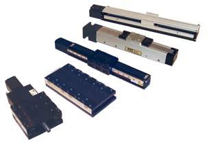
3 Daedal Electromechanical Positioning Systems Table of Contents Introduction 2-3 Parker Partners in Automation & Support 4-5 Selectable Levels of Integration 6-7 Parker Products and Technologies 8-9 Daedal Products and Technologies Daedal Engineered Solution Examples Linear Servo Motor Driven LXR Series Screw Driven Automation Overview XR Series Square Rail Linear XRS Cartesian Systems /403XE Series Positioners XE Series HD Series Linear Positioners Ultra Series Crossed Roller Ultra Precision Stages CT & 800CT Series RT Series Rotary Series Worm Driven Precision Stages ZP200 Series Vertical Lift Wedge Table Additional Products Miniature Positioners Linear Motor & Screw Driven Overview MX80L Linear Motor Driven Stages MX80S Ballscrew/Leadscrew Driven Stages MX80M Free Travel & Micrometer Driven LX80L Linear Motor PROmech LP 28 Miniature Linear Positioners PROmech LD 28 Miniature Linear Positioners 194 PROmech LD 28 Miniature Linear Positioners Belt Driven High-speed Automation Overview HPLA Series HLE-RB HLE-SR HLE-Z HZR BLMA Gantry Robot Configurations HPLA/HLE Options and Accessories Additional Products Drives and Controllers Planetary Gearheads Rotary Servo Motors 286 Frameless Motors Servo Drives & Controller Drives 290 Stepper Drives & Controller Drives 291 ACR Motion Controllers 292 Real-Time Ethernet Motion Control HMI Human Machine Interfaces Engineering Reference Welcome! Thank you for your interest in the products and systems offered by s Electromechanical Automation Division. This catalog presents Parker s perfect fit electromechanical solutions for high-precision positioning and high-speed automation. Our products and systems are recognized around the world for their functionality, performance, and reliability. The products illustrated in this catalog can be combined to form single- or multi-axis systems. These systems are offered at Selectable Levels of Integration ranging from basic single-axis mechanical tables and actuators... to multi-axis mechanical subsystems... to complete electromechanical systems and robots including motors, drives, controls, and machine interface. As you read through this catalog, you will discover that Parker offers the widest variety of electromechanical solutions that are delivered in the shortest amount of time. Still, many customers require special solutions to satisfy unique or special requirements. Parker has been providing custom engineered solutions for over 30 years to satisfy those requirements. If your application cannot be fulfilled by the complement of products found in this catalog, please contact an authorized Parker Automation Technology Center or a factory applications engineer. We are proud to present to you a complete spectrum of positioning and motion control products. We invite you to discover the advantages that can be realized by relying on Parker for products and systems which represent the very best value in the electromechanical marketplace. Sincerely, Ken Sweet General Manager Linear Motor Driven Screw Driven Miniature Positioners Belt Driven Drives & Controllers Engineering Reference Copyright 2008


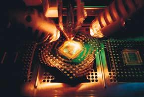
4 Positioning Systems Partners in Automation Today s automation applications demand performance in quality throughput, productivity and precision. Miniaturization of semiconductor, electronics and life science applications have created the need to partner with companies that have the experience and products to meet stringent specifications for smaller, more precise motion control solutions. Parker s dedicated electromechanical business is rapidly becoming an industry leader in providing precision connectivity to PC-based controls for target industries including: Semiconductor Electronics Computer Peripherals Life Science Medical Equipment In the industrial markets, solutions from Parker s combine speed, accuracy and high-load capacities to give machine builders and OEMs a competitive edge in applications including: Packaging Automotive Manufacturing and Assembly Printing Material Handling Military Applications Parker is about motion control engineering, manufacturing, application expertise and unparalleled customer service. Our electromechanical systems and solutions are available wherever needed around the corner or around the world. 2

5 Parker Unrivaled Support Customization and Services Unlike many other motion technologies, electromechanical applications often require custom solutions. Parker has a Custom Systems Group staffed by experienced engineers and technicians who utilize systematic processes for handling component modifications or complete one-of-akind systems. The System is the Product Many of the industrial systems shown in this catalog are built specifically to customer request and need. Parker system customers can receive many optional services such as: 3-D Custom Assembly Drawings Electronics Integration Finite Element Analysis Life Load Testing End Effector Integration High-Flex Cabling Systems Our advanced manufacturing and assembly process allows us to build quality and consistency into every element of your motion system. Each mechanical system is fully assembled prior to shipment and each component is properly handled to protect finish and appearance. Performance and specifications are verified with state-of-the-art testing, including: Cleanroom Testing Parker is equipped with particulate testing to certify materials for cleanroom ratings. EMI Testing Parker has an EMI test chamber, which allows us to test equipment to verify levels of electromagnetic interference. Precision Metrology Lab When precision is critical to your process, you need validated, proven performance data. Parker certifies all precision-grade positioners using state-of-the-art laser interferometers, and provides reports to validate accuracy and bidirectional repeatability. 24/7 Emergency Breakdown Referrals The Parker product information center at 800-C-PARKER offers live operators 24/7 to help identify replacement parts or services. Parker Automation Technology Centers Parker Automation Technology Centers are a network of premier product and service providers who can serve you locally for your automation needs. Each Automation Technology Center is certified to have completed significant product training and has the ability to provide subsystem solutions with local support. Industry s Best Lead Times #1 rated, industry-leading, on-time delivery to customerrequested ship dates. The Parker Electromechanical Automation site offers the most extensive online support tools in the industry, including: Complete online catalog FAQ database with more than 500 answers to common questions Interactive product sizing and selection tool Comprehensive CAD drawings and 3-D models for electronic and mechanical products User guides and detailed product specifications Latest software and firmware revisions Application case studies and videos Custom solutions photo library Innovative technology white papers One-on-One with a Motion Control Expert Toll-Free Applications Engineering Assistance When you have urgent questions, expert answers are only a phone call away. Our team of experienced engineers is ready to take your call. These engineers have practical field experience and can provide you with application and product assistance throughout the stages of your project and for the life of the product. For presale support, including sizing and selecting systems, call ( outside the US). For post-sale support with technical questions on programming and troubleshooting, call ( outside the US). Our staffing and support tools allow us to resolve most issues and get your project rolling in less than one hour. 3


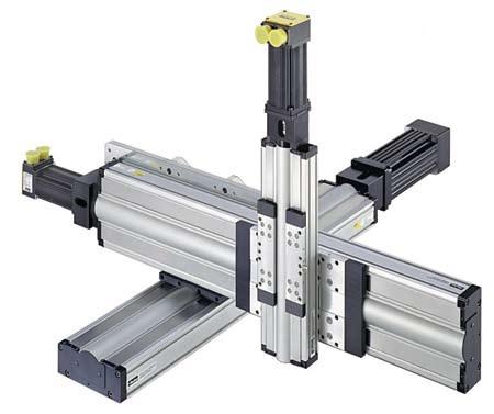
6 Positioning Systems Parker Selectable Levels of Integration Parker s Selectable Levels of Integration is a philosophy of product development and management that allows the machine builder to select an appropriate system, subsystem, or component to meet a specific need. Parker has solutions for machine builders of all types, from those who want a complete integrated system to those who want to build their own system from best of breed components. Systems Machine builders and OEMs often choose to integrate a complete electromechanical system into their machine. They have confidence in knowing that our knowledge, experience, and support will ensure that their goals are met. Minimal design engineering ensures component compatibility from a single source. Subsystems and Bundled Products For a cost-effective and efficient solution, Parker offers bundled or kitted systems. We can combine motors, gearheads, and positioning systems to deliver a configured subsystem ready for installation. Parker configuration and setup software accommodates the rest of the product line, making start-up a snap. Combining this with our custom product modification capabilities gives the machine builder an economical custom-fit solution, with reduced engineering effort, straightforward integration, and modular compatibility. Component Products We offer the broadest range of linear and rotary motion products available for automation systems. If you have the capability and experience to develop your own systems, our innovative, easy-to-use products will help you get the job done. Parker provides short lead times, large selection, and proven reliability. 4


7 Parker Selectable Levels of Integration 5


8 Positioning Systems Parker Products and Technologies Parker products are built using industry standard interfaces and market-leading features that combine great value and performance. Whether using one component or an entire system, Parker has the right solution. HMI (Human-Machine Interface) Parker offers HMI solutions for any application from simple pushbutton replacement to sophisticated networking, multimedia and data logging requirements. Parker pre-loads Interact or InteractX HMI software on PowerStation industrial computers to provide a ready-to-go HMI solution. This bundled approach reduces development and integration time for your HMI project. Motion Controllers Parker motion controllers are powerful designs that have the processing power to coordinate multiple axes of motion. Parker controllers have advanced features built in, such as kinematics transformation for the control of robots and other non-linear functions. Each Parker controller comes with free libraries for Visual Basic and Visual C++. 6
9 Parker Products and Technologies Drives Parker drives are digital designs that deliver a maximum amount of power output and performance in minimal package size. These drives have industry-leading power density and smart digital designs with features to ease integration and start-up. Motors Using advanced technologies, Parker rotary motors provide maximum performance and value. Our exposed-lamination designs provide maximum torque per package size, and the motor designs provide cogfree rotary motion for the best low-speed smoothness. Patented linear motor designs provide the greatest winding uniformity and accuracy in the industry, and range from the smallest linear motor on the market to the largest force capacity. Gearheads High-precision designs, Parker gearheads have less than three arc-min of backlash. They have an industry-leading two-year warranty. Positioning Parker multi-axis positioning tables integrate linear motors or ground ballscrews. The designs combine the low cost of extruded aluminum with machined bases allowing out of the box submicron precision. Our positioning tables are modular designs that easily accommodate flexible configurations such as XY and XYZ. Actuators Parker actuators are modular single-axis actuators that can be easily configured in multi-axis systems. These actuators are screw- or belt-driven and give the designer a great deal of flexibility to apply the right actuator technology to meet the application needs for accuracy, speed and distance. End Effectors With the broadest range of automation products in the industry, Parker provides pneumatic grippers, rotary actuators and vacuum components for a wide range of applications. Structural Framing Parker Industrial Profile Systems provide full engineering, fabrication and assembly for any structural design. We provide the profiles, fasteners and accessories to complete any system. The only limitation is your imagination. I/O The Parker I/O system is a modular and flexible remote I/O system designed to work with today s common fieldbuses. The modular design of the Parker I/O allows the user to choose the number and type of I/O points that best suit each application. Systems Parker s systems combine the breadth of our motion control solutions into XY systems, Cartesian robots, gantry systems, or completely custom configurations. 7


10 Positioning Systems Daedal Products and Technologies This catalog is divided into several sections based on primary distinguishing characteristics such as drive technology, degree of precision, travel range, and acceleration. If you don t find what you are looking for, please contact us for information on other suitable Daedal and Parker products. Linear Motor Driven Drive Mechanisms Linear Servo Motor Direct Drive Rotary Motor Bearing Systems Square Rail Screw Driven Drive Mechanisms Ground Ballscrew Ground Leadscrew Rolled Ballscrew Worm Gear Bearing Systems Square Rail Round Rail Linear Ball & Rod Cross Roller Miniature Positioners Drive Mechanisms Linear Servo Motor Ground Ballscrew Rolled Leadscrew Bearing Systems Square Rail Cross Roller Belt Driven Drive Mechanisms Timing Belt Linear Servo Motor Rack-and-Pinion Bearing Systems Polyamide Wheel Steel Wheel Square Rail Visit our Website Complete up-to-date technical assistance can be found on the web at. This includes all the latest information on current products, new product introductions, local assistance and support, plus a comprehensive Engineering Reference Library. Complete Product Catalog Product Selection Wizards Performance Charts and Graphs Engineering Data and Calculations CAD Drawings Local Service and Support Directory On-Line Purchasing Application stories and videos 8
11 Daedal Products and Technologies Screw Driven Positioners Style Standard Miniature Model Drive Type Ground Ballscrew Rolled Ballscrew Rolled Leadscrew Bearing Type Precision µm Max. Travel mm Normal Load N (lbs) Profile Width mm Max. Speed mm/s Page 404XR Square Rail (375) Best 406XR Square Rail (1390) Best 412XR Square Rail 2000* (3241) Best HD085 Square Rail (375) Better HD125 Square Rail (1390) Better HD185 Square Rail 2000* (3241) Better 402XE Recirculating Ball (205) Good 403XE Recirculating Ball (360) Good 404XE Square Rail (382) Good CT Cross Roller (290) Good ER Roller Wheel (500) (3) Good ET Roller Wheel 2000* (10000) (3) Good Ultra Cross Roller (4821) Better LN Square Rail (160) PDF** Good LP28 Square Rail (22) Better LD (10) Good MX80S Cross Roller (18) Best Linear Motor Driven Style Recommendation High- Precision High- Precision Miniature Industrial Grade Model Drive Type Slotless Ironless Ironcore Bearing Type Precision µm Normal Load N (lbs) Profile Width mm Max. Speed mm/s Page Recommendation 404LXR Square Rail (375) Best 406LXR Square Rail (1390) Best 412LXR Square Rail 3000* (3241) Best Ultra Cross Roller (4821) Best MX80L Cross Roller 200* 80 (18) Best LX80 Square Rail (13) Better T Square Rail 4060* 900 (200) (2) Better TR Square Rail 2655* 4500 (990) (2) Better BLMA Roller Wheel (674) Good Belt Driven Products Style Model Drive Type Bearing Type HPLA080 Belt Steel/Polyamide Roller Wheel HPLA120 Belt Steel/Polyamide Roller Wheel HPLA180 Belt Steel/Polyamide Roller Wheel Precision µm Max. Travel mm Normal Load N (lbs) Profile Width mm Max. Speed mm/s Page Recommendation (674) Best (1358) Best (3372) Best HLE60RB Belt Roller Wheel (150) Best HLE100RB Belt Roller Wheel (256) Good HLE150RB Belt Roller Wheel (512) Good HLE60SR Belt Square Rail (157) Best HLE100SR Belt Square Rail (377) Better LCB Belt Sliding Bearing (66) (3) Good ERV Belt Roller Wheel (807) (3) Better ER Belt Roller Wheel (50) (3) Good HZR Belt Roller Wheel (310) Better Other Products Drive Type Bearing Type Precision µm Max. Travel mm Normal Load N (lbs) Profile Width mm Max. Speed mm/s Page Recommendation Rotary Worm / Direct Servo Ball Bearing 3250 (715) RPM Better Wedge Positioners Ball Screw Square Rail (165) Better Manually Driven Micrometer Cross Roller/ Ball (500) PDF** Best Rack and Pinion Belt/Rack Roller Wheel (3372) 150 & Better * Longer travel lengths available by special order. ** PDF documents are available on our website at (2) See Catalog (3) See Catalog AU /US 9
. Parker s electromechanical systems are utilized extensively in all three areas.")


12 Positioning Systems Daedal Engineered Solutions The majority of today s positioning and motion control systems are involved in processes associated with making (manufacturing), moving (transferring), or measuring (testing). Parker s electromechanical systems are utilized extensively in all three areas. This is attributed to our ability to provide Perfect Fit solutions covering a broad spectrum of requirements at various levels of integration and complexity. Below and on the following pages are several examples of Daedal engineered Parker systems for customer-specific applications. Making The application examples shown here are a small sample of the multitude of manufacturing processes where Parker system solutions are being utilized. From factory floors to cleanrooms, Parker provides versatile motion systems and subsystems that maximize manufacturing productivity. Automotive Component Assembly Machine Tooling station positioner to replace mechanical cam. 6 inch vertical travel with electromechanical brake on ballscrew inch position repeatability Dowel holes in table base and carriage for precise mounting Strip seals on table to keep fingers and debris out of table Catheter and Stent Manufacturing for Medical Industry XY positioning for micromanufacturing of precision instruments. Miniature positioners with NEMA 16 servo motors inch resolution with linear encoder feedback Continuous duty cycle Precision grade tables with special laser interferometer testing 1 Sealant Dispensing for Engine Rocker Covers 1 Contour path CAD to motion. XYZ (18 in x 14 in x 6 in) work area High stiffness tables for cantilevered mounting Cable carriers for multi-axis system Precision ground ballscrews for smooth, quiet operation Rapid Prototype Machines 2 Automated process for fabricating dense metal parts by fusing metal powder within the focal beam of a laser. Combined linear motor, ballscrew and belt drive technologies Complete with machine base and cable management system Special straightness and flatness testing Custom engineered brackets Food and Beverage Packaging 3 Filling machine in washdown environment. Stainless steel construction FDA approved lubrication 30 inch travel; 50 lb load Continuous duty at 120 in/sec velocity; 3 g acceleration

 work area High dynamics")
 Custom end effectors Genomic Specimen Handling 3 Accurate placement of 96, 384, or 1536 well microtiter plates for DNA sequencing and analysis 2 XY (24 in x 20 in) work area")
 work area 60 in/sec velocity requirement Clean cable / air hose routing Payloads up to 130 lb Palletizer")
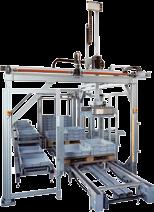
13 Daedal Engineered Solutions Moving The application examples shown here illustrate the types of material handling applications routinely solved by Parker system solutions. From overhead gantry robots to tabletop XY positioners, Parker provides the widest spectrum of material handling application solutions in the industry. 1 Electric Motor Container Handling 1 Automated transfer of product from conveyor to labeler to pallet. XYZ (80 in x 60 in x 40 in) work area Per axis repeatability of inch Complete cable management system Custom end effector Multi-Pick Storage and Retrieval System 2 Programmable order picker XYZ (20 ft x 13 ft x 3 ft) work area High dynamics (2 g accel.; 80 in/sec vel.) Custom end effectors Genomic Specimen Handling 3 Accurate placement of 96, 384, or 1536 well microtiter plates for DNA sequencing and analysis 2 XY (24 in x 20 in) work area Modular motion platform integrates into OEM machinery Attractive packaging of XY table with stainless steel protective covers Cleanroom compatible 3 Machine Tool Loader/Unloader 4 Automated machine tending for top entry machine access XZ (10 ft x 3 ft) work area 60 in/sec velocity requirement Clean cable / air hose routing Payloads up to 130 lb Palletizer for Pharmaceutical Products Product loading on automated guided vehicle XYZ (15 ft x 6 ft x 6 ft) work area Pneumatic rotary axis Custom end effector Overhead gantry mechanics allow floor space utilization 4 11


14 Positioning Systems Daedal Engineered Solutions Measuring The examples shown here showcase Parker s ability to provide high-precision motion solutions for critical test and measurement applications. From miniature microscope mounted positioners to steel framed test systems, Parker provides solutions for the widest range of precision applications and ensures performance with laser testing and certification. Surface Measurement of Turbine Blades Precise positioning of contact probes. Custom 5-axes motion mechanics Complete with machine base and cable management system Special laser interferometer certification Heavy duty construction to minimize deflection Flying Height Tester Position a test specimen to simulate hard disk drive reader head operation. 6 in x 4 in XY travel designed for high accuracy Special materials for extreme rigidity and low ESD Cleanroom compatible mechanical system Special point of measurement laser interferometer testing 2 1 Wafer Inspection Vision system raster scan. 350 mm x 350 mm work area Continuous duty cycle Cleanroom compatible mechanics Precision ballscrew or linear motor drive options Inspection of Composite Parts for Aerospace Industry 1 Precision positioning of 300 lb test specimen relative to fixed test beam. 40 in x 20 in x 360 work envelope All axes of motion aligned to test beam for entire travel range Custom 16 ft x 8 ft x 5 ft steel machine frame Complete with control panel and cable management system Camera Calibration Rig 2 Calibration of video camera used in space for vital display information. Ballscrew driven XYZ system with extended travel (144 in x 24 in x 24 in) Custom engineered brackets Pinned orthogonal Repeatable within in 12


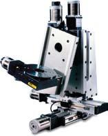
15 Linear Motor Driven high-speed, high-precision tables Positioning systems needed for many of today s high-technology applications must satisfy an ever-increasing demand for high throughput and the need for extreme precision. Semiconductor, fiber optics, computer peripherals, metrology, solar scribing, digital printing, and other high-end industries require positioning systems which demonstrate quick response, high acceleration, high velocity, and fast settling time, in conjunction with micron and submicron level positioning. Parker s linear motor product group is designed to satisfy this attribute combination of performance and precision. Products and systems in this section feature advanced direct-drive technology, which enables payloads to be directly driven by highly efficient brushless servo motors. Contents Overview 16 Specifications 17 Cable Management 18 Digital Drive Options 19 Cleanroom Option LXR Dimensions LXR Ordering Information LXR Dimensions LXR Ordering Information LXR Dimensions LXR Ordering Information Additional Products 13


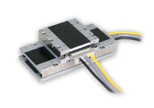
16 Linear Motor Driven Linear Servo Motor Driven 400LXR Series Linear Motor Linear motors cannot function on their own. Before motion can occur, a platform must be engineered to provide support, direction, and feedback for the linear motor. Bearings, cables, connectors, encoder, travel stops, homing sensor and other components must be performance matched and integrated to achieve desired motion and control. Pre-engineered package Performance matched components Protection from environment Laser certified precision Parker linear motor tables provide all this and more in a pre-engineered, easily mounted, ready to run package. The linear motor magnet rail is mounted to a stationary base and the forcer is mounted to the moveable carriage. The only contact between the moving carriage and the stationary base is through the linear support bearings. High-precision square rail bearings provide load support, low-friction translation, and a precise linear path. A high resolution linear encoder provides the required velocity and positional information to the motor controller, and a unique cable management system enables high performance motion with a life of 30 million cycles and beyond. Parker tables, with the slotless linear motor, are offered in three sizes: 404LXR, 406LXR, and 412LXR. Performance Matched Components The 400LXR Series linear servo motor tables achieve optimum performance by combining slotless motor technology with performance matched mechanical elements and feedback devices. Fast response, high acceleration, smooth translation, high velocity, and quick settling time describe the performance characteristics found in the 400LXR while high repeatability, precise accuracy, and sub-micron resolution define the positioning attributes. Sized to Fit The 400LXR are offered in three widths (100, 150, and 300 mm), and travel lengths up to 3 meters to accommodate the size and performance requirements of many industries including life sciences, photonics, semiconductor, digital printing, solar panel, and general automation. Designer Friendly Features and Options A vast assortment of designer friendly features and options simplify the engineering challenges often confronted with base model positioning devices. Features like the IP30 protective strip seal and long life cable management system exemplify the built-in value found in the 400LXR units. Other selectable enhancements like cleanroom compatibility, travel limit sensors, motor drives, encoder resolution, and pinning holes for tooling location, simplify machine design and integration efforts. 14


17 Linear Servo Motor Driven Flexibility and Multi-Axis Compatibility The 400LXR s selection flexibility and mounting compatibility with the 400XR ballscrew driven tables enables single-axis or complex multi-axis units to be configured in a straightforward manner. Parker s matching servo drives and motion controllers can be included to complete the motion system. Customs and Systems For specialized applications requiring customization, Parker design engineers can easily modify these tables to suit, or engineer complete interactive linear motion systems to desired specifications. Parker s 400LXR series tables have taken the mystery, difficulty and cost out of integrating linear motor tables into high throughput precision positioning applications. Linear Motor Driven Pass-Through Cabling Pre-wired, plug-in connection of the moving payload for easy hookup of user instruments or end effectors. Connector Panel Electrically shielded panel provides plug-in connectivity and quick disconnect for all signal and power requirements. High Strength Aluminum Body Extruded aluminum housing is precision machined to provide outstanding straightness and flatness. Magnet Rail Single rail of high energy rare earth magnets offers lower weight and lower cost than double magnet type. Slotless Linear Motor Provides a highly responsive, zero backlash drive system. Slotless motors offer excellent heat management, durability, and have built-in thermal sensor and hall sensors Linear Guidance System The highly engineered carriage and bearing system effectively counters the combined problematic effects of heat, high-speed and high acceleration. Integral Linear Encoder Protected non-contact feedback with selectable resolutions to 0.1 micron. Z channel is factory aligned to home sensor for precise homing. Limit/Home Sensors Proximity sensors establish end of travel and home location and are easily adjustable over entire length to restrict the travel envelope. Quick Change Cabling Innovative cable transport module offers extended life (30 million cycles) and a simple cable changing system for preventative maintenance. Protective Seals Hard shell aluminum cover combined with stainless steel strip seals provide IP30 protection to interior components as well as enhances overall appearance. 15
18 Linear Motor Driven 400LXR Series Specifications 2D & 3D CAD files Download from parkermotion.com Model 404LXR 406LXR 412LXR Motor 8 Pole 8 Pole 12 Pole 12 Pole Rated Load kg (lb) 45 (99) 180 (396) 180 (396) 950 (2090) Maximum Acceleration Maximum Velocity Encoder Resolution: 0.1 µm 0.5 µm 1.0 µm 5.0 µm Sine Output Positional Repeatability Encoder Resolution: 0.1 µm 0.5 µm 1.0 µm 5.0 µm Sine Output (m/sec) Gs ± 1.0 µm ± 1.0 µm ± 2.0 µm ± 10.0 µm (Interpolation Dependent) Peak Force N (lb) 180 (40) 225 (50) 330 (75) 1000 (225) Continuous Force N (lb) 50 (11) 75 (17) 110 (25) 355 (80) Carriage Mass (kg) Travel Dependent Specifications Accuracy* (µm) Unit Weight (Kg) Positional Travel Resolution Straightness 404LXR 406LXR 406LXR 412LXR (mm) 0.1 & Flatness 8-Pole 8-Pole 12-Pole 12-Pole * Accuracy stated is at 20 C, utilizing slope correction factor provided Encoder Specifications Description Input Power Output (Incremental) Reference (Z Channel) Specification 5 VDC ±5% 150 ma Square wave differential line driver (EIA RS422) 2 channels A and B in quadrature (90 ) phase shift. Synchronized pulse, duration equal to one resolution bit. Repeatability of position is unidirectional moving toward positive direction. Limit and Home Specifications Description Input Power Output Repeatability Specification +5 to +24 VDC 60 ma (20 ma per sensor) Hall Effect Specifications Description Input Power Output Output form is selectable with product: Normally Closed Current Sinking Normally Open Current Sinking Normally Closed Current Sourcing Normally Open Current Sourcing All types Sink or Source max of 50 ma Limits: ±10 microns (unidirectional) Home: See Z channel specifications Specification +5 to +24 VDC, 30 ma Open Collector, Current Sinking, 20 ma Max 16


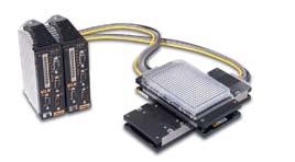
19 400LXR Cable Management Options Cable Transport Module The LXR s Cable Transport Module offers the convenience of plug and play connectivity for fast, easy table installation and quick change replacement. This system of cable management includes the highest quality high-flex ribbon cable with a life rating of 30 million cycles, a cable track with support brackets, a quick change carriage cartridge, and a plug-in connector panel housing. It also provides a pass-through connection and cabling for customer application. This transport module option is ideal for high throughput continuous duty requirements where downtime is not acceptable. Quick Change Cartridge Cable Extensions Flying Leads Terminations 2-Axis System w/expandable Cable Management 404LXR 404LXR Cable Transport Module Connection Ends 406LXR/412LXR Cable Transport Module Order Code Order Extension Cable Code Length (m) Termination CM02 No Extension Cables CM Flying Leads CM Flying Leads CM Gemini Conn. CM Gemini Conn. CM Aries/ViX Conn. CM Aries/ViX Conn. Linear Motor Driven OEM Cable System The LXR s unharnessed cable system is offered for OEMs and others who have independent methods of routing and managing cables. These systems offer the quick change cartridge, pass-through connection and round high-flex cables in lengths of 3.0 or 7.5 meters. They are available with flying lead end terminations, as well as Gemini or Aries connectors. 406LXR with OEM cables and flying leads OEM Cable System Order Code Order Extension Cable Code Length (m) Termination CM Flying Leads CM Flying Leads CM Gemini Conn. CM Gemini Conn. CM Aries/ViX Conn. CM Aries/ViX Conn. User Pass-Through Cabling Cable concerns regarding routing and durability for payload or instrument signals are addressed by the passthrough connectivity feature included with both of the LXR cable management systems. Nine pin D-connectors provided on the carriage (with the transport module units) and the cable connecting block combine with high-flex, long life cables for easy setup and dependable performance. Note: Extension cables are available and can be ordered separately (3 meters); (7.5 meters). Pre-wired plug-in connection to the moving payload Nine user conductors for end-effectors or instruments High-flex long life cables: Ribbon Cable Transport Module System Round Cable OEM System 17


20 Linear Motor Driven 400LXR Series Options and Accessories Simple Configuration Digital Drive Options All digital drives ordered in the LXR part number configuration come set up with a motor file including electrical parameters to set continuous and peak currents, current loop compensation values, and default gain settings. Users will have the ability to override these parameters for special application requirements. Tuning is easy to use and intuitive for users and is available via a variety of methods. The motor and loading information must be known by the drive to determine the baseline tuning gains. These are simple parameter entries the user can complete with the help of standard Parker supplied front-end software tools. Aries Series Aries Digital Drive The Aries option allows the user to select the fully digital compact servo drive from Parker. Look for upcoming additions to the LXR configured with the Aries ETHERNET Powerlink version as well as the Aries Drive/Controller versions. Order Codes: A62 A63 Gemini Series GV Digital Servo Drive The Gemini Series offers a fully digital servo drive configured directly in the LXR part numbering system. Order Codes: A4 A7 A40 GV Digital Controller/Servo Drive The Gemini Series servo drive/controller option allows the user to order a preconfigured digital drive/controller for a single-axis easy to use solution. Order Codes: A5 A6 A8 A9 A41 A42 For complete details on drive product features and specifications, please refer to the Drives & Controllers section of this catalog. Dowel Pinning Options Order Codes: P1 P2 P3 Standard dowel pin locating holes P1 are offered on all 400LXR units to facilitate repeatable mounting of tooling or payload. In addition, pinning options P2 and P3 are offered for precise orthogonal mounting of the second axis in a multi-axis system. In this case, the bottom side of the table base is match drilled and reamed to the first axis to provide exact orthogonal location. This convenient option eliminates concerns regarding contamination or damage often associated with machining for locating pins in an assembled unit. In some instances a 404LXR pinning adapter may be required part number Two locating dowel holes, right (P1 option) shown in 404LXR carriage 18


21 400LXR Series Options and Accessories Cleanroom Preparation Option Order Codes: R2 Cleanroom compatible linear tables are often required for laboratory and production applications in industries such as semiconductor, life science, electronics, and pharmaceuticals. 400LXR tables with cleanroom preparation were tested in Parker s vertical laminar flow work station, which utilizes ULPA filters to produce an environment having a cleanliness of class 1 prior to testing. were tested in a variety of orientations with sampling both below the table and at the carriage mounting surface. Laminar flow rate is 0.65 inches W.C. 404LXR with cleanroom Class 10 modification Linear Motor Driven Special cleanroom testing can be provided upon request. For more information on cleanroom testing, contact a Parker Applications Engineer at About Cleanrooms A room in which the concentration of airborne particles is controlled within defined limits. Federal Standard 209E statistically defines the allowable number of particles per cubic foot of air. The chart below describes the conditions that must be maintained for the cleanroom to have a specific class rating. Class Number of Allowable Particles (Measured particle size in microns µm) Standard Cleanroom Preparation Stringent cleaning and handling measures Cleanroom rated lubrication Strip seal replaced with hard shell cover Testing at 4.5 inches below table 400LXR Cleanroom Compatibility Table Velocity Testing at carriage mounting surface 4.5 Below Table Class At Carriage Surface 250 mm/sec mm/sec mm/sec mm/sec mm/sec Toe Clamp Accessories Part Number: (404LXR) (406LXR) (412LXR) Toe clamps for mounting 400LXR tables are ordered separately. Note that 400LXR Series toe clamps are not interchangeable with toe clamps for 400XR Series tables. 19
22 Linear Motor Driven 404LXR Dimensions 2D & 3D CAD files Download from parkermotion.com Dimensions (mm) Qty (2) Dia.Pin Holes Qty (4) Mounting Holes (top) M6 x 1.0 Thd "E" M6 C'bore Centers of Toe Clamps LIMITS MOTOR ENC./HALL AUX (Pin Holes) 88.0 (Mounting Holes) P/N AUXILLARY P/N ENCODER-HALLS P/N LIMIT-HOME P/N MOTOR CABLE OEM Cables (Strip Seal/Hardcover) 18.0 "A" Top View (With Cable Transport Module) LIMITS MOTOR ENC./HALL AUX. Cable Module (Strip Seal/Hardcover) Z4-Negative Z3-Center Z2-Positive 1/2 Travel mm 1/2 Travel mm A Recommended Clearance for Cable Carrier Front View Z-Channel Location "A" Qty (2) Dia. Pin Holes A Minimum Clearance Required for Extension Cable Connector Clearance OEM Cables/Strip Seal OEM Cables/Hardcover Cable Module/Strip Seal Cable Module/Hardcover End Views A-A M5 x 0.8 Tapped Holes Qty "D" Holes 15.0 "B" mm = "C" Bottom View 15.0 "B" mm = "C" Model Travel (mm) Dimensions (mm) A B C D E 404T00LXR T01LXR T02LXR T03LXR T04LXR T05LXR T06LXR T07LXR T09LXR T11LXR T13LXR T15LXR T17LXR T19LXR
23 404LXR Ordering Information Fill in an order code from each of the numbered fields to create a complete model order code. 1 Series Travel mm 8 Pole Motor T00 50 T T T T T T T T T T T T T Model LXR Linear Motor 4 Mounting M Metric 5 Grade P Order Example: Precision # $ 404 T04 LXR M P D13 H3 L2 CM09 Z2 E2 R1 A4 P1 9 Cable Management CM01 No Cables Free Travel CM02 Cable Transport Module (only) CM m OEM Cable Set-FL CM m OEM Cable Set-FL CM m OEM Cable Set-Gemini CM m OEM Cable Set-Gemini CM07 Cable Trans Mod. w/3.0 m-fl* CM08 Cable Trans Mod. w/7.5 m-fl* CM09 Cable Trans Mod. w/3.0 m-gemini* CM10 Cable Trans Mod. w/7.5 m-gemini* CM m OEM Cable Set-Aries/ViX CM m OEM Cable Set-Aries/ViX CM13 Cable Trans Mod. w/3.0 m-aries/vix* CM14 Cable Trans Mod. w/7.5 m-aries/vix* * Extension cable for pass through connection is available and can be ordered separately: # (3 meters); # (7.5 meters) 0 Z Channel Location* Z1 None Z2 Positive End Position Z3 Center Position Z4 Negative End Position * Refer to dimensions on previous page Linear Motor Driven 6 Drive Type D3 Free Travel (No Motor) D13 8 Pole Motor 7 Home Sensor H1 None-Free Travel (only) H2 N.C. Current Sinking H3 N.O. Current Sinking H4 N.C. Current Sourcing H5 N.O. Current Sourcing 8 Limit Sensor L1 None-Free Travel (only) L2 N.C. Current Sinking L3 N.O. Current Sinking L4 N.C. Current Sourcing L5 N.O. Current Sourcing! Encoder Option E1 None E2 1.0 µm Resolution E3 0.5 µm Resolution E4 0.1 µm Resolution E5 5.0 µm Resolution E7 Sine Output Environmental R1 Strip Seal R2 Hard Cover w/class 10 Cleanroom Prep R3 Hard Cover without Cleanroom Prep # Digital Drive A1 No Drive A4 Gemini Drive GV-U6E A5 Gemini Controller/Drive GV6-U6E A6 Gemini Controller/Drive GV6K-U6E A62 Aries Drive AR-04AE 21 $ Pinning Option P1 No multi-axis pinning P2 * X axis transfer pinning to Y or Z axis - 30 arc-sec P3 * Y axis transfer pinning to X axis - 30 arc-sec * Transfer pinning to XR from LXR requires additional bracket and an EPS request. Call for details.
24 Linear Motor Driven 406LXR Dimensions 2D & 3D CAD files Download from parkermotion.com 8 or 12 Pole Slotless Motor Dimensions (mm) Ctr'd Ctr'd 80.0 Ctr'd 25.0 Qty (2) Dia.Pin Holes M6 x 1.0 Thd. Carriage Mtg. Holes Qty Ctr'd Ctr'd Ctr'd Ctr'd 55.0 Top View (with Cable Transport Module) Z4* Negative 1/2 Travel - 10 mm Z3* Center 8 Pole Carriage = 288 mm 12 Pole Carriage = 373 mm 1/2 Travel - 10 mm Z2* Positive Top View (with OEM Cable System) 69.9 Front View (Z-Channel Location) *Z2, Z3, Z4 shows Carriage Center-line Location for Selected Z-Channel Position 1/2 "A" "C" = "D" "A" 50.0 Ctr'd "C" = "D" 15.0 "B" Mtg. Holes M6 x 1.0 Th'd End View (with OEM Cable System) Toe Clamp Mounting Optional Ctr'd Ctr'd Ctr'd "F" = "G" Qty (2) Dia.Pin Holes Ctr'd Ctr'd Bottom View "F" = "G" Model "E" C'bored Mtg.Holes - (Farside) for M6 Cap Screws Travel (mm) Dimensions (mm) 8 Pole 12 Pole A B C D E F G 406T01LXR T02LXR T03LXR T04LXR T05LXR T06LXR T07LXR T08LXR T09LXR T10LXR T11LXR T12LXR T13LXR T14LXR
25 406LXR Ordering Information Fill in an order code from each of the numbered fields to create a complete model order code. 1 Series Travel mm 8 Pole Motor 12 Pole Motor T01 50 T T T T T T T T T T T T T Model LXR Linear Motor 4 Mounting M Metric 5 Grade P Order Example: Precision # $ 406 T08 LXR M P D13 H2 L2 CM09 Z2 E2 R1 A4 P1 9 Cable Management CM01 No Cables Free Travel CM02 Cable Transport Module (only) CM m OEM Cable Set-FL CM m OEM Cable Set-FL CM m OEM Cable Set-Gemini CM m OEM Cable Set-Gemini CM07 Cable Trans Mod. w/3.0 m-fl* CM08 Cable Trans Mod. w/7.5 m-fl* CM09 Cable Trans Mod. w/3.0 m-gemini* CM10 Cable Trans Mod. w/7.5 m-gemini* CM m OEM Cable Set-Aries/ViX CM m OEM Cable Set-Aries/ViX CM13 Cable Trans Mod. w/3.0 m-aries/vix* CM14 Cable Trans Mod. w/7.5 m-aries/vix* * Extension cable for pass through connection is available and can be ordered separately: # (3 meters); # (7.5 meters) 0 Z Channel Location* Z1 None Z2 Positive End Position Z3 Center Position Z4 Negative End Position * Refer to dimensions on previous page Linear Motor Driven 6 Drive Type Free Travel (No Motor) D3 8 Pole Motor (No Motor) D5 12 Pole Motor (No Motor) Linear Motor D13 8 Pole Motor Carriage D15 12 Pole Motor Carriage 7 Home Sensor H1 None-Free Travel (only) H2 N.C. Current Sinking H3 N.O. Current Sinking H4 N.C. Current Sourcing H5 N.O. Current Sourcing 8 Limit Sensor L1 None-Free Travel (only) L2 N.C. Current Sinking L3 N.O. Current Sinking L4 N.C. Current Sourcing L5 N.O. Current Sourcing! Encoder Option E1 None E2 1.0 µm Resolution E3 0.5 µm Resolution E4 0.1 µm Resolution E5 5.0 µm Resolution E7 Sine Output Environmental R1 Strip Seal R2 Hard Cover w/class 10 Cleanroom Prep # Digital Drive A1 No Drive A4 Gemini Drive GV-U6E A5 Gemini Controller/Drive GV6-U6E A6 Gemini Controller/Drive GV6K-U6E A62 Aries Drive AR-04AE $ Pinning Option P1 No multi-axis pinning P2 * X axis transfer pinning to Y or Z axis - 30 arc-sec P3 * Y axis transfer pinning to X axis - 30 arc-sec * Transfer pinning to XR from LXR requires additional bracket and an EPS request. Call for details. 23
26 Linear Motor Driven 412LXR Dimensions 2D & 3D CAD files Download from parkermotion.com 12 Pole Slotless Motor Dimensions (mm) Ctr'd Qty 8 Mounting Holes (Top) M6 x 1.0 Thd. Note: Additional holes are provided for direct mounting, toe clamp mounting and pin holes for the 404LXR and 406LXR (CAD files) Ctr'd Ctr'd Ctr'd Qty (2) Dia. Pin Holes Ctr'd Top View Z4* Negative Z3* Center 1/2 Travel - 10 mm 1/2 Travel - 10 mm Z2* Positive Toe Clamp Mounting (Optional) Front View *Z2, Z3, Z4 shows Carriage Center-line Location for Selected Z-Channel Position End View "A/2" "A" C L Qty (2) Dia. Pin Holes Ctr'd Ctr'd "C" = "D" C L (See Notes) Ctr'd (See Note) Notes: Base mounting holes for models Ctr'd 412T10 and 412T12 are patterned from one hole on centerline Bottom View "C" = "D" (See Notes) "B" Mounting Holes M8 x 1.25 Tapped Thru and C'bored (farside) for M6 x 1.0 Cap Screw Model Travel (mm) Dimensions (mm) A B C D 412T01LXR T02LXR T03LXR T04LXR T05LXR T06LXR T07LXR T08LXR T09LXR T10LXR T11LXR T12LXR
27 412LXR Ordering Information Fill in an order code from each of the numbered fields to create a complete model order code. 1 Series Travel mm 8 Pole Motor T T T T T T T T T T T T Model LXR Linear Motor 4 Mounting M Metric 5 Grade P Order Example: Precision 6 Drive Type D5 Free Travel (No Motor) D15 12 Pole Motor 7 Home Sensor H1 None-Free Travel (only) H2 N.C. Current Sinking H3 N.O. Current Sinking H4 N.C. Current Sourcing H5 N.O. Current Sourcing # $ 412 T09 LXR M P D15 H3 L3 CM09 Z2 E2 R1 A7 P1 9 Cable Management CM01 No Cables Free Travel CM02 Cable Transport Module (only) CM m OEM Cable Set-FL CM m OEM Cable Set-FL CM m OEM Cable Set-Gemini CM m OEM Cable Set-Gemini CM07 Cable Trans Mod. w/3.0 m-fl* CM08 Cable Trans Mod. w/7.5 m-fl* CM09 Cable Trans Mod. w/3.0 m-gemini* CM10 Cable Trans Mod. w/7.5 m-gemini* CM m OEM Cable Set-Aries/ViX CM m OEM Cable Set-Aries/ViX CM13 Cable Trans Mod. w/3.0 m-aries/vix* CM14 Cable Trans Mod. w/7.5 m-aries/vix* * Extension cable for pass through connection is available and can be ordered separately: # (3 meters); # (7.5 meters) 0 Z Channel Location* Z1 None Z2 Positive End Position Z3 Center Position Z4 Negative End Position * Refer to dimensions on previous page! Encoder Option E1 None E2 1.0 µm Resolution E3 0.5 µm Resolution E4 0.1 µm Resolution E5 5.0 µm Resolution E7 Sine Output Environmental R1 Strip Seal R2 Hard Cover w/class 10 Cleanroom Prep Linear Motor Driven 8 Limit Sensor L1 None-Free Travel (only) L2 N.C. Current Sinking L3 N.O. Current Sinking L4 N.C. Current Sourcing L5 N.O. Current Sourcing # Digital Drive A1 No Drive A7 Gemini Drive GV-U6E A8 Gemini Controller/Drive GV6-U6E A9 Gemini Controller/Drive GV6K-U6E A63 Aries Drive AR-04AE 25 $ Pinning Option P1 No multi-axis pinning P2 * X axis transfer pinning to Y or Z axis - 30 arc-sec P3 * Y axis transfer pinning to X axis - 30 arc-sec * Transfer pinning to XR from LXR requires additional bracket and an EPS request. Call for details.

28 Linear Motor Driven Other Servo Drive Products from Parker Trilogy I-Force Ironless Linear Motors Trilogy RIPPED Ironcore Linear Motors Parker Trilogy s I-Force ironless motors offer high force and rapid accelerations in a compact package. Parker Trilogy s patented I-beam shape, with its overlapping windings, allows for a higher power density in a smaller motor, improved heat removal, and added structural stiffness. A forgiving air gap and no attractive forces allow for easy installation and zero cogging during motion. 5 different cross sections (110, 210, 310, 410, and ML50) up to 8 poles Compact size with high force density and superior heat removal Air and water cooling Vacuum rated to 10-6 torr Ultra high-flex cable standard Parker Trilogy s RIPPED ironcore linear motors, with their patent-pending anti-cog technology, can produce the large forces needed for many industrial applications without the roughness associated with traditional ironcore linear motors. The RIPPED family is well suited for a broad range of extremely demanding applications. Patent-pending anti-cog technology for extremely smooth motion 5 different cross sections Single magnet row for high performance at an economical price Connector module allows for quick installation and easy cable management Ultra high-flex cable standard Trilogy ML50 Ironless Linear Motors Parker Trilogy s ML50 ironless linear motors are optimized to provide high forces with minimum moving mass, making them the ideal choice for applications requiring very high, continuous accelerations of relatively light payloads. Demanding applications such as high-speed pick and place, die sorting, injection mold loading/unloading, and textile weaving can all benefit from unique characteristics of the ML50 motors. Optimized for ultra high acceleration of light payloads Compact size with high force density and superior heat removal Connector module for quick installation and easy cable management Ultra high-flex cable standard Series I-Force Ironless ML50 Ironless Ripped Ironcore Continuous force 5.5 to lbf (24.5 to N) 43 to 192 lbf (189 to 852 N) 13 to 501 lbf (56 to 2230 N) Peak force 45.5 to 883 lbf (202.5 to 3928 N) 190 to 857 lbf (847 to 3811 N) 43 to 1671 lbf (190 to 7433 N) Cogging force Zero Zero Low Attractive force Zero Zero High Magnet tracks Dual Dual Single Heat dissipation Good Good Better Applications Rapid accelerations, extremely smooth motion Ultra high accelerations of relatively light payloads High force, lower cost for long travels 26


29 Other Servo Drive Products from Parker Trilogy Ironless and Ironcore Linear Motor Positioning Linear Motor Driven Parker linear positioners utilize our high-performance Trilogy ironless and ironcore linear motors in a pre-engineered, easily integrated, ready-to-run package. The principal design goal for these positioners is to achieve high performance at an economical cost while preserving the design flexibility to accommodate customization. Options include multi-axis configurations, bellows, and a variety of cable management systems. Single- or dual-bearing rail positioners to better match the performance and cost requirements for each application Magnetic encoders for industrial environments or optical encoders with resolutions down to 0.1 micron Multiple carriage options Open frame, bellows or two covers available Zero cogging (ironless) or extremely smooth (ironcore) Counterbalance options for vertical applications Velocities to 7 m/s For more information on these Trilogy products, refer to our complete Linear Motor Catalog # Series T1S / T1D T2S / T2D T3S / T3D T4S / T4D TR7 TR9 TR16 Motor 110 ironless 210 ironless 310 ironless 410 ironless R7 ironcore R9 ironcore R16 ironcore Travel lengths (mm) 100 to to to to to to to 3694 Load (kg) 11.3*/13.5** 27.2*/45.3** 72*/108** 90*/181** 200** 300** 450** Acceleration (G s) *** Velocity (m/s) up to 3 up to 5 up to 5 up to 5 up to 5 up to 5 up to 5 Peak force (N) Continuous force (N) Resolution (micron) 0.1 to to to to to to to 5.0 Repeatability (micron) ±1 ±1 ±1 ±1 ±1 ±1 ±1 * Single rail load specifications ** Dual rail load specifications *** Consult factory for higher accelerations Peak velocity is encoder dependent Repeatability is resolution dependent Recommended loads based on motor size and typical performance. Bearing specifications exceeded listed specifications. Consult factory for higher loads. 27


30 Linear Motor Driven Other Servo Drive Products from Parker RD Direct Drive Rotary Stages /products Parker Direct Drive Rotary Stages feature a robust construction and high performance in a compact package, providing smooth, near frictionless motion with zero backlash. Featuring an integral brushless DC servo motor, these rotary stages offer several distinct advantages over traditional worm gear-driven stages. The elimination of the worm gearing offers the ability to reduce wear with zero backlash while exhibiting near frictionless motion. Its high positioning accuracy, solely based on the stage's encoder, provides repeatability within 2 encoder counts, with resolutions ranging to 1.4 arc-seconds. The RD Direct Drive features speeds up to 700 RPM with significant torque capability. Applications Electronic assembly Fiber Optics Medical Packaging Pharmaceutical Recommended Uses Precision rotary motion ZERO backlash Compact Rugged For more information on Parker s direct drive rotary products, please refer to catalog Unique design integrated brushless motor features high copper slot and rare earth magnet for maximum torque efficiency Aluminum or stainless steel precision ground top plate for accurate mounting Robust bearing design for high load capacity Sub D connectors for plug & play operation and easy hook-up. In-line rotary encoder for direct position feedback. Also includes once per rev index mark Motor rotor and top plate shaft as one-piece construction for high stiffness 28
31 Screw Driven automation tables Precise multi-axis positioning systems play an integral part in today s semiconductor, computer peripheral, solar power, flat panel, life sciences, lab automation, biomedical and electronics industries. The demands for tighter specifications, improved throughput and consistent quality have become increasingly stringent. Because of the complexity associated with these systems, many manufacturers insist on a single source supplier to eliminate multiple vendor design incompatibilities and delivery conflicts. With over forty years experience as a global leader in the development of products and technology, Parker provides the most advanced, easy to integrate high-precision electromechanical systems. Contents Overview XR Series Precision Linear Positioners XRS Cartesian Systems /403XE Series Positioners XE Series Positioners HD Series Industrial Linear Positioners Ultra Series Precision Stages CT & 800CT Series RT Series Rotary R Series Worm Drive Rotary ZP200 Series Vertical Lift Wedge Table Additional Products 29


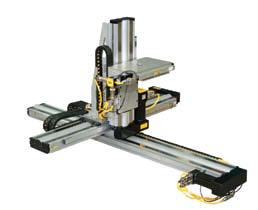
32 Screw Driven Overview Parker High-precision Systems and Services include: Selectable Levels of Integration that let you pick the product or system which suits your need and fits your capability The most comprehensive array of products in the industry Advanced product development Seamless integration with other Parker components including servo motors, motor drives, controls, interfaces, actuators, pneumatics, and structural components Modular construction from standard catalog tables or custom systems designed and built to specification Global Parker support network (1-800-C-PARKER) Easy, multi-axis connectivity Submicron precision Velocities up to 1.5 meters/second Cleanroom and vacuum compatible Thorough testing and certification Product Comparisons: Parker high-precision screw driven tables are divided into families (or groups) which are distinguished by the primary bearing style and precision. All tables are offered with several drive mechanism options and are designed for direct connection to standard frame size stepper or servo motors. Each family is shown here for a quick comparison based on key parameters. 400XR Series Precision Linear Positioners Page XRS Cartesian Systems Page The key attributes of the XR Series Positioners are high strength, long travel range, and high precision utilizing square rail technology. These tables can satisfy the vast majority of high-precision positioning applications in hightechnology markets. Travel Range: 2000 mm Load Capacity: 1470 kg Maximum Speed: 1.5 meters/sec Duty Cycle: 100% Repeatability: ±1.3 µm (bidirectional) Utilizing our standard and precision XR series positioning tables, Parker has developed the XRS family of Cartesian systems. These systems offer broad range of scalability, a unique mix of technology, and a rugged long lasting product. Travel Range: 300 x 300 mm to 1000 x 600 x 150 mm Load Capacity: 25 kg Maximum Speed: 2 m/s on one axis Duty Cycle: 100% Repeatability: ±6 to ±50 micron per axis 30


33 Overview 402/403XE Series Ballscrew Positioners Page HD Series Industrial Linear Positioners Page The steel base constructed 402/403XE series offers rigid compact positioning for the cost conscious motion applications. A highly integrated ballscrew, bearing retainer system results in a very low overall height and high payload capacities. Travel Range: 655 mm Load Capacity: 160 kg Maximum Speed: 0.8 m/s Duty Cycle: 100% Repeatability: ±5 µm By incorporating a deep channel design, coupled with a belt seal and industrial grade ballscrews, the HD series offers an economical solution for industrial positioning. Perfect for use in many industries from packaging to liquid dispensing, the HD series is a robust, rigid, industrial grade positioner, without the precision of the XR, for a lower cost. Travel Range: 2 m Load Capacity: 1470 kg Maximum Speed: 1.5 m/s Duty Cycle: 100% Repeatability: ±8 µm Screw Driven 404XE Series Series Ballscrew Positioners Page Ultra Series Precision Stages Page The 404XE is an economy version of the 404XR. This product is ideal for applications where the precision of the XR is not needed, but the wide flat stance of the XR family benefits the application details. Travel Range: 700 mm Load Capacity: 125 kg Maximum Speed: 1.4 m/s Duty Cycle: 100% Repeatability: ±30 µm The Ultra Series features precision cross roller bearings, an optional open frame design, and lead screw, ballscrew, or linear motor drive options. Travel Range: 0.5 m Load Capacity: 2187 kg Maximum Speed: 1.5 m/s Duty Cycle: 100% Repeatability: ±0.5 µm 31
34 Screw Driven Overview 100CT & 800CT Series Ballscrew Positioners Page R Series Worm Drive Rotary Page CT 200RT Series Rotary Page CT These tables offer ultra-smooth highly precise motion and positioning. They are much stronger providing higher load carrying capability and offer a 100% duty cycle. Travel Range: 300 mm Load Capacity: 400 pounds Maximum Speed: 250 mm/sec Duty Cycle: 100% Repeatability: ±1.3 μm (bidirectional) Rotary provide continuous motor driven rotary Unique self-compensating preload to limit backlash Solid or thru bore construction Robust bearing design for high-load capacity Built-in limit switches Aluminum construction with stainless steel top plate The Rotary Stage Series offers an unparalleled combination of high accuracy and high-load capacity. These rotary stages utilize a precision worm gear with the worm flexed against the gear to ensure a proper mesh. This feature provides high repeatability with very smooth operation. Additionally, the rotary stages incorporate an oversized preloaded cross roller bearing, offering exceptional stiffness and load capacity. Travel Range: continuous Load Capacity: 600 kg Maximum Speed: 30 RPM Duty Cycle: 50% Repeatability: 12 arc-sec ZP200 Vertical Lift Wedge Stages Page motion and precise positioning. They are offered in 5, 6, 8, 10, and 12 inch diameters. Their low profile and light weight make them ideal indexing units for multi-axis combination with high-precision linear tables. Travel Range: continuous Load Capacity: 90 kg Maximum Speed: 150 deg/sec Duty Cycle: 50% Repeatability: 0.2 arc-min (unidirectional) The ZP200 is a unique vertical lift stage providing up to 25 mm lift with no horizontal translation in a small package. The ZP200 uses ballscrew technology and a square rail bearing design. Travel Range: 25 mm Load Capacity: 75 kg Maximum Speed: 0.4 m/s Duty Cycle: 100% Repeatability: ±3 μm 32


35 Overview Additional Capabilities Page These pre-engineered tables are utilized primarily by OEMs for requirements which exceed Parker s standard catalog offering. They include high-precision square rail units, belt driven round rail units, heavy duty cross roller units, and high-speed rotary units. An overview of these products is provided at the end of this section. Visit our website at for complete specifications on these products, PDF data sheets and CAD drawing downloads. Screw Driven 100BT Motor Drives and Controls (See pages ) 300AT 402LN 506ET, 506ST 406LN 400ST 33
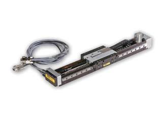
36 Screw Driven 400XR Series Features 400XR Series Precision Linear Positioners Pre-engineered package Performance matched components Environmental protection Laser certified precision Typical Enhancements Limit/home position sensors Linear encoder feedback Cleanroom preparation Multi-axis brackets & adapters Selectable motor mounts Servo motors and drives Programmable controls Cable management system 412XR 406XR 404XR 401XR 402XR Limit/Home Encoder 401XR 402XR 404XR 406XR 412XR The 400XR precision linear positioners family has achieved global recognition for consistent accuracy, reliable performance, high strength, and unmatched versatility. The XRs have excelled in industries such as life sciences, fiber optics and instrumentation, where the highest degree of precision is required. And yet, because of the rugged construction, strength, and sealed design, these units have been used extensively for industrial automation applications (packaging, automotive, etc). 401XR 402XR 404XR 406XR 412XR Travel (mm) Load (kg) Acceleration (m/sec 2 ) The XR family offers an unrivaled array of features and options which are easily matched to fit any application, from the very basic to the highly complex. Premier performance, modular compatibility, and quick delivery have made these tables the perfect building blocks for precision multi-axis systems. 34


37 400XR Series Features High Strength Aluminum Body Extruded aluminum housing is precision machined to provide outstanding straightness and flatness. Square Rail Linear Bearing These tables are equipped with square rail carriage support bearings which provide high load carrying capabilities, smooth precise motion and dependable performance. High Efficiency Ballscrew Drive Precision ground, or rolled ballscrew drive (5, 10, 20, 25, 32 mm lead) offers high throughput, efficiency, accuracy and repeatability. Limit/Home Sensors Proximity sensors establish end of travel and home location and are easily adjustable over entire length to restrict the travel envelope. Motor Mounts A large selection of servo and stepper motor sizes plus selectable mounting configurations (in-line, parallel) permit a wide variety of motor mounting possibilities. IP30 Rated Strip Seals 1 An anodized aluminum cover combined with stainless steel strip seals provide IP30 protection to interior components as well as enhance the overall appearance. Encoders The linear encoder option offers direct positional feedback of the carriage location. The rotary shaft encoder couples directly to the drive shaft to nullify any incurred mechanical error (particularly useful with the parallel motor mount). Not shown. Shaft Brake The electromagnetic shaft brake option couples directly to the drive screw and is employed primarily on vertical axes to halt carriage motion during a power loss. Not shown. Convenient Mounting Slots Continuous T-slots along the side of the table body provide a convenient means of mounting the table to a work surface as well as mounting accessories to the table. Positive Pressure Port A standard port (1/8 NPT) for pressurizing the interior to prevent particle intrusion. (Standard on 404XR, 406XR, 412XR units.) Easy Lube System A standard option on some models, enables easy access for ballscrew and bearing lubrication. 4 Screw Driven Cleanroom Preparation Class 10 cleanroom preparation is a standard option for the 400XR series. For detailed technical information on cleanroom preparation, contact Parker s Application Engineering Department at

38 Screw Driven 401XR and 402XR Specifications 401XR (41 mm wide profile) 402XR Series (58 mm wide profile) The 401XR and 402XR Series positioners enhance the 400XR family of precision linear positioners, addressing applications which involve precise positioning of smaller payloads within a very small space envelope. These ballscrew driven positioners were developed to address the needs of industries such as photonics, life sciences, semiconductor, and instrumentation, where technology advancements dictate miniaturization of work envelopes. 402XR Carriage equipped with dowel locating holes for repeatable positioning of tooling or payload. 401XR Common Specifications Bidirectional Repeatability 2 mm lead 5 or 10 mm lead Travel/Screw Lead Dependent Specifications Travel (mm) Positional Accuracy* (µm) Straightness & Flatness Input Inertia (10-5 kg-m 2 ) 401XR 402XR 401XR 402XR Max Screw Speed (revs/sec) Unit Weight (kg) Precision Standard Precision Standard 401XR 402XR 2 mm 10 mm 5 mm 10 mm 401XR 402XR 401XR 402XR *Accuracy stated is at 20 C utilizing slope correction factor provided. µm ±1.3 ±1.3 Precision* Standard 401XR 402XR 401XR 402XR Duty Cycle % Maximum Acceleration m/sec 2 (in/sec 2 ) 20 (773) 20 (773) 20 (773) 20 (773) Normal Load Capacity (1) kgf (lbs) 50 (110) 100 (220) 50 (110) 100 (220) Axial Load Capacity (1) 2 mm lead 5 or 10 mm lead kgf (lbs) 5.5 (12.1) 15.5 (34.2) ± (84) ±5 ± (12.1) 15.5 (34.2) Drive Screw Efficiency % ±12 38 (84) Maximum Breakaway Torque Nm (in-oz) 0.03 (4.2) (12.0) 0.03 (4.2) (12.0) Maximum Running Torque (2) Nm (in-oz) (4.0) 0.08 (11.3) (4.0) 0.08 (11.3) Linear Bearing Coefficient of Friction Ballscrew Diameter 2 mm lead 5 or 10 mm lead mm 6 8 Carriage Weight kg (lbs) (0.1) 0.11 (0.25) (0.1) 0.11 (0.25) * Requires linear encoder option E3 or E4. (1) Refer to life load charts found later in this section. (2) Ratings established at 2 rps

39 404XR Specifications 404XR Series (95 mm wide profile) The 404XR is a sleek compact positioner (47.3 x 95 mm profile) capable of carrying 170 kg loads up to a distance of 700 mm. Its quick and accurate positioning capability can be attributed to a high strength extruded housing, square rail ball bearing system, and precision ground ballscrew drive. With its low profile design the 404XR is ideal for height restricted applications, and its lightweight construction makes it well suited as secondary axes on multi-axis systems. These units offer a wide array of easily adapted options and accessories which permit easy configuration to specific requirements. Common Specifications Precision Standard Bidirectional Repeatability (5) µm ±1.3 ±3 Duty Cycle Ballscrew Leadscrew % 100 Maximum Acceleration m/sec 2 (in/sec 2 ) 20 (773) 20 (773) Normal Load Capacity (1) kgf (lbs) 170 (375) 170 (375) Axial Load Capacity (2) Ballscrew Leadscrew Drive Screw Efficiency Ballscrew Leadscrew kgf (lbs) 90 (198) % (198) 25 (55) Maximum Breakaway Torque Nm (in-oz) 0.13 (18) 0.18 (26) Maximum Running Torque (3) Nm (in-oz) 0.11 (16) 0.17 (24) Linear Bearing Coefficient of Friction Ballscrew Diameter mm Carriage Weight kg (lbs) 0.70 (1.55) 0.70 (1.55) Parallel Motor Mount (with limit/home sensor pack option) (1) Refer to life load charts found later in this section. (2) Axial load for parallel mount is limited by a maximum input torque of 25 Nm. (3) Ratings established at 2 rps. (4) Positional accuracy applies to in-line motor configurations only. Contact factory for parallel motor specifications. (5) Consult factory for specifications with linear encoder. (6) Consult factory for higher screw speeds. Screw Driven Travel/Screw Lead Dependent Specifications Travel (mm) (4) (5) Positional Accuracy (µm) Straightness Input Inertia (10-5 kg-m 2 ) & Flatness Precision Standard 5 mm 10 mm 20 mm 37 Max Screw Speed (6) (revs/sec) Unit Weight (kg)
 this durable table is ideal as the base unit in a multi-axis system.")
 Common Specifications Precision Standard Bidirectional Repeatability (5) µm ±1.")
40 Screw Driven 406XR Specifications 406XR Series (150 mm wide profile) The 406XR can position high loads (up to 630 kgf) over distances up to two meters. Because of its size and strength (270 Nm, 200 lb-ft moment load capacity) this durable table is ideal as the base unit in a multi-axis system. From high resolution to high throughput, selectable ballscrew leads (5, 10, 20, 25 mm) make the desired resolution/velocity ratio easy to achieve, and stainless steel seal strips alleviate environmental concerns. Parallel Motor Mount (with limit/home sensor pack option) Common Specifications Precision Standard Bidirectional Repeatability (5) µm ±1.3 ±3 Duty Cycle % Maximum Acceleration m/sec 2 (in/sec 2 ) 20 (773) 20 (773) Normal Load Capacity (1) kgf (lbs) 630 (1390) 630 (1390) Axial Load Capacity (2) 0 to 600 mm Travel 700 to 2000 mm Travel kgf (lbs) 90 (198) 90 (198) 200 (440) Drive Screw Efficiency % Maximum Breakaway Torque 0 to 600 mm Travel 700 to 2000 mm Travel Maximum Running Torque (3) 0 to 600 mm Travel 700 to 2000 mm Travel Nm (in-oz) 0.13 (18) Nm (in-oz) 0.11 (16) 0.18 (26) 0.39 (55) 0.17 (24) 0.34 (48) Linear Bearing Coefficient of Friction Ballscrew Diameter 0 to 600 mm Travel 700 to 2000 mm Travel mm 16 Carriage Weight kg (lbs) 2.7 (5.94) 2.7 (5.94) (1) Refer to life load charts found later in this section. (2) Axial load for parallel mount is limited to: 140 lbs for the 5, 10 and 20 mm lead drives: 104 kg (230 lbs) for 25 mm lead drives (3) Ratings established at 2 rps. (4) Positional accuracy applies to in-line motor configurations only. Contact factory for parallel motor specifications. (5) Consult factory for specifications with linear encoder. (6) Consult factory for higher screw speeds. Travel/Screw Lead Dependent Specifications Travel (mm) (4) (5) Positional Accuracy (µm) Straightness Input Inertia (10-5 kg-m 2 ) & Flatness Precision Standard 5 mm 10 mm 20 mm 25 mm Max Screw Speed (6) (revs/sec) Unit Weight (kg)

41 412XR Specifications 412XR Series (285 mm wide profile) The 412XR is a rugged heavy duty linear table (285 mm x 105 mm profile) that enables massive loads (up to 1470 kgf) to be precisely positioned over distances up to two meters. Single point easy lube port is standard on carriage assembly for simple servicing and a convenient adapter plate (# ) is available for easy X-Y configuration. An unrivaled array of options combined with mounting compatibility with the smaller 400XR tables makes the 412XR ideal as the base unit for multiaxis positioning of heavier payloads. Common Specifications Standard Screw Lead mm 5, 10, Bidirectional Repeatability (4) µm ±5 ±5 Duty Cycle % Maximum Acceleration m/sec 2 (in/sec 2 ) 20 (773) 20 (773) Normal Load Capacity (1) kg (lbs) 1470 (3241) 1470 (3241) Axial Load Capacity kg (lbs) 200 (441) 460 (1014) Drive Screw Efficiency % Maximum Breakaway Torque Nm (in-oz) 0.61 (86) 0.76 (108) Maximum Running Torque (2) Nm (in-oz) 0.55 (78) 0.69 (98) Linear Bearing Coefficient of Friction Ballscrew Diameter mm Carriage Weight kg (lbs) 12 (27) 13 (28) (1) Refer to life load charts found later in this section. (2) Ratings established at 2 rps. (3) Positional accuracy applies to in-line motor configurations only. Contact factory for parallel motor specifications. (4) Consult factory for specifications with linear encoder. (5) Consult factory for higher screw speeds. Screw Driven Travel/Screw Lead Dependent Specifications Travel (mm) Positional Accuracy (µm) (3) (4) Straightness & Flatness Input Inertia (10-5 kg-m 2 ) 5 mm 10 mm 25 mm 32 mm Max Screw Speed (5) (revs/sec) 5, 10, 25 mm 32 mm Unit Weight (kg) 5, 10, 25 mm mm 39
42 Screw Driven 400XR Series Specifications 400XR Series Life/Load The following performance information is provided as a supplement to the product specifications pages. The following graphs are used to establish the table life relative to the applied loads. The useful life of a linear table at full catalog specifications is dependent on the forces acting upon it. These forces include both static components resulting from payload weight, and dynamic components due to acceleration/ deceleration of the load. In multi-axes applications, the primary positioner at the bottom of the stack usually establishes the load limits for the combined axes. When determining life/load, it is critical to include the weight of all positioning elements that contribute to the load supported by the primary axis. Catalog load specifications are rated for 100 million inches of travel or 2,540 km. For final evaluation of life vs load, including off center, tension, and side loads refer to the charts and formulas found on our web site at. Normal Load (Compression) These graphs provide a rough cut evaluation of the support bearing life/load characteristics. The curves show the life/load relationship when the applied load is centered on the carriage, normal (perpendicular) to the carriage mounting surface Life with Compression Load 401XR 402XR Axial Load (Thrust) These graphs illustrate table ballscrew life relative to the axial load. Life (Km) Thrust Load 401XR 2 mm lead 401XR 5 mm lead 402XR 5 mm lead 402XR 10 mm lead Life (Km) Catalog values are rated at 2,540 Km of life Load (N) Catalog values are rated at 2,540 Km of life Load (N) Thrust Load Life with Compression Load XR 406XR 412XR Life (Km) Life (Km) Catalog values are rated at 2,540 Km of life Load (N) Load (N) XR 20 mm lead x 16 mm dia XR 10 mm lead x 16 mm dia XR 5 mm lead x 16 mm dia XR 25 mm lead x 25 mm dia XR 10 mm lead x 25 mm dia XR 5 mm lead x 25 mm dia. Catalog values are rated at 2,540 Km of life 412XR 5 mm lead x 25 mm dia. 412XR 10 mm lead x 25 mm dia. 412XR 25 mm lead x 25 mm dia. 412XR 32 mm lead x 32 mm dia. 40
43 400XR Series Specifications 400XR Series Bearing Life/Load* Life (Km) Life (Km) Normal Load (Compression) Life with Compression or Tension Load Catalog values are rated at 2,540 Km of life Load per Bearing (N) Life with Side Load Catalog values are rated at 2,540 Km of life 404XR 406XR 412XR 404XR 406XR 412XR These charts are to be used in conjunction with the corresponding formulas found in the product manuals at to establish the life/load for each bearing (4 per table). Several dimensions, which are specific to each linear positioning table model, and the load geometry are required for these computations. These dimensions are supplied in the catalog information for each positioner. The dimensions are referenced as follows: d1 bearing block center-to-center longitudinal spacing d2 bearing rail center-to-center lateral spacing da Rail center-to-carriage mounting surface d1 d2 da 404XR XR XR Refer to Parker s website for moment loading and other engineering data. Screw Driven Load per Bearing (N) *For 401XR and 402XR moment loading capacities, please refer to the maintenance manual. 41

44 Screw Driven 400XR Series Options Home or Limit Sensor Options End of Travel and Home Sensors for the 400XR series are available in a variety of styles. The sensors can be ordered as part of the table or as separate components with the associated mounting hardware or in an enclosed sensor pack. A 5 meter high-flex extension cable (Part No ) is included for use with the 401XR thru 406XR models having the locking connector option. NPN (Sinking) or PNP (Sourcing) Normally Closed (N.C.) or Normally Open (N.O.) Flying Leads or Locking Connector Specifications Input Power Output Wire Color Code 5-30 VDC, 20 ma 100mA max (+) Supply: Brown ( ) Supply: Blue NO Output: Black NC Output: White 401XR Limits and Home Sensor Black Brown Blue 150 mm Connector Cable Sensor Target 20,5 13,0 30,0 Sensor / Bracket Detail Order Code Part Number* Switch Type Logic Cable Length Connector Option H2 or L N.C. Sinking 3.0 m Flying Leads H3 or L N.O. Sinking 3.0 m Flying Leads H4 or L N.C. Sourcing 3.0 m Flying Leads H5 or L N.O. Sourcing 3.0 m Flying Leads H6 or L N.C. Sinking 150 mm Locking Connector H7 or L N.O. Sinking 150 mm Locking Connector H8 or L N.C. Sourcing 150 mm Locking Connector H9 or L N.O. Sourcing 150 mm Locking Connector H11 or L11 See chart below N.C. Sinking See chart below Sensor Pack H12 or L12 See chart below N.O. Sinking See chart below Sensor Pack H13 or L13 See chart below N.C. Sourcing See chart below Sensor Pack H14 or L14 See chart below N.O. Sourcing See chart below Sensor Pack * Applies to 401XR thru 406XR models. 412XR models have limits and homes internally mounted with a connector termination. Sensor triggers (targets) ordered separately. Sensor Pack Cable NOMINAL CABLE LENGTH 75mm Description Part Number 3 Meters Meters XR with Limit and Home Sensor Pack Wire Color Function Pin Number Red +5 to +24 VDC A Blue Limit 1 (LXR ) B Orange Limit 2 (LXR +) C Green Home D Black Ground E Green/Yellow Shield Shield Case 42


 150 mm Screw Driven 401XR with")
45 400XR Series Options Linear Encoder Options (Tape Scale) A linear position feedback device which mounts directly to the table carriage. (Factory installation required.) 1.0 µm resolution 0.5 µm resolution 0.1 µm resolution Specifications Input Power Output Resolution Cable Length 5 VDC, 150mA A/B quadrature and reference mark, differential line drive output 1.0, 0.5, 0.1 micron 3 m Rotary Encoder Option Modular rotary encoder couples directly to the drive screw for position feedback and is easily field installed. The rotary encoder cannot be installed with the brake assembly option counts/rev Note: Dimensions shown apply to 404XR and 406XR models. Consult factory for 412XR dimensions. Specifications Input Power Output Resolution Cable Length 9.5 Dia. Shaft Mounting Hole 38.1 (2) 3.7 Dia. Holes on 46.0 Dia. B.C VDC, 135 ma A/B quadrature and reference mark, differential line drive output 1250 lines/rev equals 5000 counts post quadrature (1 µm with 5 mm lead ballscrew) 150 mm Screw Driven 401XR with Linear Encoder plus Sensor Pack Brake Assembly Option Electromagnetic brake assembly used to prevent backdriving in vertical applications. The brake option includes a 5 m extension cable. The brake option is easily field installed. The brake option cannot be installed with the rotary encoder option. "A" "B" 404XR with Brake Option Holding Dimensions (mm) Table Series Part Number Input Power Torque A B 401XR/402XR 404XR VDC, 0.46 A 2.0 Nm XR VDC, 0.5 A 4.5 Nm XR VDC, 0.75 A 9.0 Nm


46 Screw Driven 400XR Series Options Dowel Pinning Options* Standard dowel pin locating holes are offered on most 400XR units to facilitate repeatable mounting of tooling or payload.* In addition, pinning options are offered for precise orthogonal mounting of the second axis in a multi-axis system. In this case, the bottom side of the table base is match drilled and reamed to the first axis to provide exact orthogonal location. This convenient option eliminates concerns regarding contamination or damage often associated with machining for locating pins in an assembled unit. *Not available with 401XR or 402XR or 50 mm travel 404XR. Two locating dowel pins shown in carriage 44
47 400XR Series Accessories 400XR Series Accessories Riser Plate Accessory Used to raise the table base to provide clearance for motors. Toe Clamp Accessory Used for convenient outboard mounting of table to a base plate, riser plates, Z-axis bracket, or other 400XR table. All hardware is included. Table Series 401XR/402XR Part Number: / (2) Mtg. Holes for M6 Cap Screw 22.0 High Model "B" Ctr'd "A" Part Number 401XR XR XR XR XR "C" High 15.0 Dimensions (mm) A B C 401XR XR XR Part Number: (2) Mtg. Holes for M6 Cap Screw Model (1) Mtg. Hole for M6 Low Head Cap Screw Part Number 404XR XR XR XR Part Number: XR Part Number: Ctr'd (2) Mtg. Holes for M6 Screws Screw Driven 25.0 Ctr'd Ctr'd XR Part Number: High (4) Mtg. Holes for M6 Screws 25.0 Ctr'd XR Part Number: (3) Mtg. Holes for M6 Screws Ctr'd Ctr'd Ctr'd Ctr'd


48 Screw Driven 400XR Series Configurations 400XR Multi Axis Configurations Base Axis (X) * 401XR Orientation 401XR 50 mm >50 mm Second Axis (Y or Z)* 402XR 404XR 404LXR 406XR 406LXR 412XR 412LXR X-Y X-Y Cartesian X-Z Wedge X-Z Side Mount X-Y XR X-Y Cartesian X-Z X-Z Side Mount X-Y Direct Mount* X-Y Carriage to Carriage X-Y Cartesian 404XR Right Hand 404LXR X-Y Cartesian Left Hand X-Z X-Z Side Mount X-Y Direct Mount* Direct Mount* Direct Mount* Direct Mount* X-Y Carriage to 406XR Carriage LXR X-Y Cartesian X-Z X-Z Side Mount XR 412LXR Direct Mount* Direct Mount* Direct Mount* Direct Mount* X-Y or Toe Clamp or Toe Clamp or Toe Clamp or Toe Clamp X-Y Cartesian ZP 200 Wedge * An adaptor plate ( ) is required whenever the X-axis is a parallel motor mount model. If the Y-axis is 404XR with 50 mm stroke, a special plate or toe clamp option is required. X-Y or Toe Clamp or Toe Clamp
49 400XR Series Configurations 400XR Multi Axis Configurations These diagrams show the most popular variations of multiaxis configurations. Both standard and custom brackets are available. Standard X-Y orientation will place the X axis motor at the 6 o clock position and the Y axis motor at the 3 o clock position. X Z Y Screw Driven Figure 1 Two Axis (X-Y) Horizontal Mounting Figure 2 Two Axis (X-Z) Vertical Mounting Figure 3 Two Axis (X-Y) Inverted Mounting Figure 4 Two Axis-Carriage to Carriage (Y Axis Inverted) Figure 5 Two Axis (X-Y) Cartesian Horizontal Mounting Figure 6 Three Axis (X-Y-Z) Cartesian Horizontal Mounting Figure 7 Three Axis (X-Z-Y) Horizontal Mounting Figure 8 Three Axis (X-Y-Z) Horizontal Mounting Figure 9 Three Axis (X-Y-Z) Inverted Mounting 47
50 Screw Driven 401XR Dimensions 2D & 3D CAD files Download from parkermotion.com 401XR Dimensions Dimensions (mm) 34.0 ctr'd mm Dowel Hole Slip Fit ctr'd. Top View 92.0 M4 X 0.7 Th'd "J" (mid-travel) "F" "G" mm dia. Shaft Optional Encoder Package (4) Tapped Mtg. Holes 15.6 Motor Pilot Dia Optional Limit/Home Sensor Pack Enlarged End View (with Encoder and Limit/Home Sensor Pack Option) Front View "I" End View "A" "D" "C" = "E" "C" "B" "H" 18.0 Ctr'd Bottom View Clearance holes for M4 Low head screws Model Travel (mm) Dimensions (mm) A B C D E J XR XR XR XR XR Motor Size Order Code Dimensions (mm) F G H I SM 16 M NEMA 23/SM 23 M NEMA 17 M BE 23 M In-Line Motor Adapters Used to easily accommodate the mounting of different servo or stepper motors dia dia. M3 x 0.5 Th'd on bolt circle 22.1 dia. #4-40 Clearance on bolt circle 38.2 dia dia. M4 x 0.7 Th'd M4 x 0.7 Th'd on bolt circle on bolt circle SM 16 NEMA 17 SM 23 or NEMA 23 BE 23 48
51 402XR Dimensions 402XR Dimensions Dimensions (mm) mm dia. Shaft Optional Limit/Home Sensor Pack 50.0 Ctr'd 4 mm Dowel Hole Slip Fit.022 Top View Front View "A" Qty. "D" M4 x 0.7 Th'd "J" (mid-travel) "B" "F" "G" "H" 57.5 End View Optional Encoder Package 57.1 (4) Tapped Mtg. Holes Motor Pilot Dia Enlarged End View (with Encoder and Limit/Home Sensor Pack Option) Screw Driven Bottom View Clearance holes for M4 Low head screws 28.0 Ctr'd Model Travel (mm) Dimensions (mm) A B D J XR XR XR XR XR XR Motor Size Order Code Dimensions (mm) F G H SM 16 M NEMA 23/SM 23 M NEMA 17 M BE 23 M In-Line Motor Adapters Used to easily accommodate the mounting of different servo or stepper motors dia 20.0 dia. M3 x 0.5 Th'd on bolt circle 22.1 dia. #4-40 Clearance on bolt circle 38.2 dia dia. M4 x 0.7 Th'd M4 x 0.7 Th'd on bolt circle on bolt circle SM 16 NEMA 17 SM 23 or NEMA 23 BE 23 49
52 Screw Driven 404XR Dimensions 2D & 3D CAD files Download from parkermotion.com 404XR Dimensions 25.0 Ctr'd Ctr'd 8 Mtg. Holes (Top) M6 X 1.0 Thd. Dimensions (mm) 8.0 dia. (ballscrew) 6.35(.25") (leadscrew) 83.0 Ctr'd 85.0 Ctr'd Dowel Holes for 4 mm Pins 2 Holes (Top) Slip Fit.022 1/2 "A" "C" 75.0 = "D" 50.0 Ctr'd Top View Front View "A" "E" Ctr'd "F" Ctr'd "C" 75.0 = "D" Optional Home/Limit Switch Optional Toe Mounting Clamp End View Optional Linear Encoder Ctr'd 50.0 Ctr'd Dowel Holes for 4 mm Pins 2 Holes (Bottom) Slip Fit Ctr'd Bottom View "B" C'bored Mtg. Holes (Far Side) for M6 Low Head Cap Screws (included) 2.5 mm Grip Slot for Std. M4 Square Nut 4 Slots Typ Typ. 4.2 Typ. View showing slots in extruded base 7.5 Typ. Model Travel (mm) Dimensions (mm) A B C D E F XR XR XR XR XR XR XR XR XR XR XR XR
53 404XR Dimensions 404XR In-Line Motor Mounting In-line motor mounting allows the motor to be mounted directly to the drive screw via the selected motor coupling. Used to easily accommodate the mounting of different frame sizes. These adapter plates can be ordered separately by part number below Ctr'd Ctr'd ("A") (See Table Dwg.) Motor Size 33.0 Ctr'd Order Code "P" "K" 69.9 "L" Max. Motor Shaft Ø 46.0 Ctr'd Motor Motor Mount This Side 16.0 Ctr'd (4) Tapped Mtg. Holes 1/2 "M" 83.0 "M" Motor Pilot Dia. Dimensions (mm) Dimensions (mm) 1/2 "N" Ctr'd "N" K L M N P SM 16 M NEMA 23 M NEMA 34 M NEO 70 M Ctr'd Screw Driven (4) Mtg. Holes For M3 Screws on bolt circle 20.1 Dia. Motor Pilot (4) Mtg. Holes for M4 Screws on bolt circle 38.2 Dia. Motor Pilot (4) Mtg. Holes for M5 Screws on bolt circle 60.1 Dia. Motor Pilot (4) Mtg. Holes for M5 Screws on bolt circle SM 16 NEMA 23 NEOMETRIC 70/SMN060 NEMA Dia. Motor Pilot 404XR Parallel Motor Mounting Parallel motor mounting is employed whenever a shorter overall unit length is needed. The motor is positioned along the sides or bottom of the table as designated by position A, B, or C. (No coupling required.) SM 16 ("A") Y NEMA Motor Mount This Side Z 13.0 Table Motor Motor Size 96.0 Table Y (mm) 96.0 Dimensions Z (mm) Motor Shaft Ø SM SM 23/BE NEMA ,0 (4) Mtg. Holes for M3 Screws on bolt circle 45,0 37,0 Ctr'd NEMA 23 58,0 37,0 Ctr'd 23,0 Ctr'd 20,1 Motor Pilot ,0 23,0 Ctr'd 1.0 Motor POSITION A (Not compatible with sensor pack option) 70.5 Motor POSITION C Motor POSITION B (4) Mtg. Holes for M4 Screws on bolt circle 38,2 Dia. Motor Pilot 51
54 Screw Driven 406XR Dimensions 2D & 3D CAD files Download from parkermotion.com 406XR Dimensions Ctr'd Ctr'd 50.0 Ctr'd 25.0 Ctr'd (20) Mtg. Holes (Top) M6 X 1.0 Thrd. Dimensions (mm) "H" 46.0 Ctr'd Ctr'd Ctr'd Ctr'd 3.7 Dowel Holes for 5 mm Pins 2 Holes (Top) Slip Fit.022 "C" = "D" 1/2 "A" 80.0 Ctr'd Top View Front View "A" 50.0 Ctr'd "B" Mtg. Holes M6 x 1.0 Thd. "C" = "D" Optional Home/Limit Switch Optional Toe Clamp Mounting (< _ 600 mm travel) 20.0 (> _ 700 mm travel) End View Optional Linear Encoder Ctr'd Ctr'd Ctr'd 41.3 Dowel Holes for 5 mm Pins 2 Holes (Bottom) Slip Fit.022 "F" = "G" Slot for Std. M4 Square Nut 2 Slots (Top) 73.5 Typ Typ. View of Slots in Extrusion Slot for Std. Typ. M5 Square Nut 2 Slots (Bottom) 73.5 Typ. "E" C'bored Mtg. Holes (Far Side) for M6 Cap Screws 8 mm Grip "F" Spaces = "G" Ctr'd Bottom View Travel Ballscrew Dimensions (mm) Model (mm) Ø A B C D E F G H XR XR XR XR XR XR XR XR XR XR XR XR XR XR
55 406XR Dimensions 406XR In-Line Motor Mounting In-line motor mounting allows the motor to be mounted directly to the drive screw via the selected motor coupling. ("A") (See Table Dwg.) "K" 14.0 "L" (4) Tapped Mtg. Holes 1/2 "M" "M" Dimensions (mm) Used to easily accommodate the mounting of different frame sizes. These adapter plates can be ordered separately by part number below. Motor Size "P" Order Code Motor Motor Mount This Side Max. Motor Shaft Ø Dimensions (mm) 1/2 "N" Motor Pilot Dia. K L M N P MPP092 M NEMA 23/SM 23 M NEMA 34 M NEO 34 M NEO 70 M NEO 92 M "N" Screw Driven Ctr'd Ctr'd Ctr'd Ctr'd Ctr'd Ctr'd Ctr'd Ctr'd (4) Mtg. Holes for M4 Screws on bolt circle 38.1 Dia. Motor Pilot NEMA 23 or SM 23 (4) Mtg. Holes for M5 Screws on bolt circle 60.0 Dia. Motor Pilot (4) Mtg. Holes for M5 Screws on bolt circle 73.1 Dia. Motor Pilot (4) Mtg. Holes for M6 Screws on bolt circle NEO 70 / SMN060 NEMA 34 or NEO 34 MPP Dia. Motor Pilot 406XR Parallel Motor Mounting Parallel motor mounting is employed whenever a shorter overall unit length is needed. The motor is positioned along the sides or bottom of the table as designated by position A, B, or C. (No coupling required.) ("A") "Y" Sq. NEMA Motor Mount This Side "Z" 14.0 C L Table C L Motor Motor Size C L Table Y (mm) Dimensions Z (mm) Motor Shaft Ø MPP mm NEMA NEO NEO mm SM23/BE Motor POSITION A (Not compatible with Sensor Pack option) Motor POSITION C Motor POSITION B 53
56 Screw Driven 412XR Dimensions 2D & 3D CAD files Download from parkermotion.com 412XR Dimensions Ctr'd Mounting Holes (Top) M6 x 1.0 Thd. Note: Additional holes are provided for direct mounting, toe clamp mounting and pin holes for the 404XR/LXR and 406XR/LXR. (see CAD files) Dimensions (mm) Ctr'd Ctr'd Ctr'd Dowel Holes E" 8.0 mm Pins 2 Holes (Top) Slip Fit Ctr'd Top View Toe Clamp Mounting (Optional) "A/2" Front View "A" Dowel Holes E" 8.0 mm Pins 2 Holes (Bottom) Slip Fit End View Ctr'd Ctr'd 11.4 Notes: -Base mounting holes for model 412T10 and 412T12 are patterned from one hole on centerline "C" 100 = "D" (See Notes) Ctr'd (See Notes) Ctr'd Bottom View X-Y Adapter Plate # (Used to mount any 404XR, 406XR or 412XR with toe clamps) "C" 100 = "D" (See Notes) "B" Mounting Holes M8 x 1.25 Tapped (Bottom Mounting) C'bored for M6 x 1.0 Cap Screws (Top Mounting) Model Travel (mm) Dimensions (mm) A B C D 412T T T T T T T T T T
57 412XR Dimensions 412XR In-Line Motor Mounting In-line motor mounting allows the motor to be mounted directly to the drive screw via the selected motor coupling. ("A") (See Table Dwg.) "K" "L" 1/2 "M" "M" Dimensions (mm) Used to easily accommodate the mounting of different frame sizes. These adapter plates can be ordered separately by part number below. "N" (4) Tapped Mtg. Holes Motor Pilot Dia. "N" 1/2 "N" Motor Size Order Code Dimensions (mm) K L M N MPP092 M M105, SMN100 M NEMA 34 M NEO 34 M NEO 70 M NEO 92 M Screw Driven Ctr'd 53.0 Ctr'd Ctr'd Ctr'd Ctr'd Ctr'd 53.0 Ctr'd Ctr'd (4) Mtg. Holes for M4 Screws on bolt circle NEO 70 / SMN dia. Motor Pilot (4) Mtg. Holes for M5 Screws on bolt circle 73.2 dia. Motor Pilot (4) Mtg. Holes for M6 Screws on bolt circle 80.1 dia. Motor Pilot (4) Mtg. Holes for M8 Screws on bolt circle NEMA 34 or NEO 34 MPP092 M105 / SMN dia. Motor Pilot 412XR Parallel Motor Mounting Parallel motor mounting is employed whenever a shorter overall unit on length is needed. The motor bolt is circle positioned along the sides or bottom of the table as designated by position A, B, or C. (No coupling required.) Dimensions Motor Mount This Side C L Table C L Motor 75.0 Motor Size Bolt Circle (mm) C L Table Pilot Ø (mm) Shaft Ø MPP mm NEMA NEO NEO mm NEO mm C L Motor POSITION A C L Motor POSITION B 55
58 Screw Driven 401XR Ordering Information Fill in an order code from each of the numbered fields to create a complete model order code Series * Travel mm * Model XR Order Example: Linear Table 4 Mounting M Metric XR M S D9 H3 L2 C3 M2 E2 R1 8 Limit Sensor ** L1 None L2 N.C. Current Sinking Flying Leads L3 N.O. Current Sinking Flying Leads L4 N.C. Current Sourcing Flying Leads L5 N.O. Current Sourcing Flying Leads L6 N.C. Current Sinking Locking Connector L7 N.O. Current Sinking Locking Connector L8 N.C. Current Sourcing Locking Connector L9 N.O. Current Sourcing Locking Connector L11 N.C. Current Sinking Sensor Pack L12 N.O. Current Sinking Sensor Pack L13 N.C. Current Sourcing Sensor Pack L14 N.O. Current Sourcing Sensor Pack 5 Grade S P 6 Drive Screw * D3 10 mm Lead D9 2 mm Lead Standard Precision (E3 or E4 encoder option required) 7 Home Sensor ** H1 None H2 N.C. Current Sinking Flying Leads H3 N.O. Current Sinking Flying Leads H4 N.C. Current Sourcing Flying Leads H5 N.O. Current Sourcing Flying Leads H6 N.C. Current Sinking Locking Connector H7 N.O. Current Sinking Locking Connector H8 N.C. Current Sourcing Locking Connector H9 N.O. Current Sourcing Locking Connector H11 N.C. Current Sinking Sensor Pack H12 N.O. Current Sinking Sensor Pack H13 N.C. Current Sourcing Sensor Pack H14 N.O. Current Sourcing Sensor Pack 9 Motor Coupling C1 No Coupling C2 6.3 mm (0.25 in) Bore Oldham C3 6.3 mm (0.25 in) Bore Bellows C5 9.5 mm (0.375 in) Bore Bellows C24 5 mm (0.20 in) Bore Oldham C25 5 mm (0.20 in) Bore Bellows 0 Motor Mount M2 SM 16 In-Line Mounting M3 NEMA 23 In-Line Mounting M37 NEMA 17 In-Line Mounting M61 BE 23 In-Line Mounting! Encoder Option E1 None E2 1.0 µm Resolution E3 0.5 µm Resolution E4 0.1 µm R1 Required Designator * Drive Screw Lead Availability Travel 401XR 2 mm 10 mm ** 50 mm stroke 401XR may only allow room for 2 sensors in sensor pack. 56
59 402XR Ordering Information Fill in an order code from each of the numbered fields to create a complete model order code Order Example: XR M S D9 H3 L2 C3 M2 E2 R1 1 Series * Travel mm * Model XR Linear Table 4 Mounting M Metric 5 Grade S P 6 Drive Screw * D2 5 mm Lead D3 10 mm Lead Standard Precision (E3 or E4 encoder option required) 7 Home Sensor H1 None H2 N.C. Current Sinking Flying Leads H3 N.O. Current Sinking Flying Leads H4 N.C. Current Sourcing Flying Leads H5 N.O. Current Sourcing Flying Leads H6 N.C. Current Sinking Locking Connector H7 N.O. Current Sinking Locking Connector H8 N.C. Current Sourcing Locking Connector H9 N.O. Current Sourcing Locking Connector H11 N.C. Current Sinking Sensor Pack H12 N.O. Current Sinking Sensor Pack H13 N.C. Current Sourcing Sensor Pack H14 N.O. Current Sourcing Sensor Pack 8 Limit Sensor L1 None L2 N.C. Current Sinking Flying Leads L3 N.O. Current Sinking Flying Leads L4 N.C. Current Sourcing Flying Leads L5 N.O. Current Sourcing Flying Leads L6 N.C. Current Sinking Locking Connector L7 N.O. Current Sinking Locking Connector L8 N.C. Current Sourcing Locking Connector L9 N.O. Current Sourcing Locking Connector L11 N.C. Current Sinking Sensor Pack L12 N.O. Current Sinking Sensor Pack L13 N.C. Current Sourcing Sensor Pack L14 N.O. Current Sourcing Sensor Pack 9 Motor Coupling C1 No Coupling C2 6.3 mm (0.25 in) Bore Oldham C3 6.3 mm (0.25 in) Bore Bellows C4 9.5 mm (0.375 in) Bore Oldham* C5 9.5 mm (0.375 in) Bore Bellows C24 5 mm (0.20 in) Bore Oldham C25 5 mm (0.20 in) Bore Bellows *NEMA 23 frame size only (M3, M61) 0 Motor Mount M2 SM 16 In-Line Mounting M3 NEMA 23 In-Line Mounting M37 NEMA 17 In-Line Mounting M61 BE 23 In-Line Mounting! Encoder Option E1 None E2 1.0 µm Resolution E3 0.5 µm Resolution E4 0.1 µm R1 Required Designator Screw Driven * Drive Screw Lead Availability Travel 402XR 5 mm 10 mm
60 Screw Driven 404XR Ordering Information Fill in an order code from each of the numbered fields to create a complete model order code # $ Order Example: XR M S D33 H4 L2 C3 M4 E1 B1 R1 P1 1 Series Travel mm * (no pinning available) Model XR Linear Table 4 Mounting M Metric 5 Grade S P Standard Precision (only available with D2, D3, D4 drive screws) 6 Drive Screw D1 Free Travel D2 5 mm Ballscrew D3 10 mm Ballscrew D4 20 mm Ballscrew (standard grade only) D31 1 mm V Thread Leadscrew D32 2 mm V Thread Leadscrew D33 5 mm V Thread Leadscrew D V Thread Leadscrew D Acme Thread Leadscrew 7 Home Sensor Assembly (one sensor) H1 None-Free Travel (only) H2 N.C. Current Sinking Flying Leads H3 N.O. Current Sinking Flying Leads H4 N.C. Current Sourcing Flying Leads H5 N.O. Current Sourcing Flying Leads H6 N.C. Current Sinking Locking Connector* H7 N.O. Current Sinking Locking Connector* H8 H9 H11 H12 H13 H14 N.C. Current Sourcing Locking Connector* N.O. Current Sourcing Locking Connector* N.C. Current Sinking Sensor Pack** N.O. Current Sinking Sensor Pack** N.C. Current Sourcing Sensor Pack** N.O. Current Sourcing Sensor Pack** 8 Travel Limit Sensor Assembly (two sensors) L1 None-Free Travel (only) L2 N.C. Current Sinking Flying Leads L3 N.O. Current Sinking Flying Leads L4 N.C. Current Sourcing Flying Leads L5 N.O. Current Sourcing Flying Leads L6 N.C. Current Sinking w/locking Connector* L7 N.O. Current Sinking w/locking Connector* L8 N.C. Current Sourcing w/locking Connector* L9 N.O. Current Sourcing w/locking Connector* L11 N.C. Current Sinking Sensor Pack** L12 N.O. Current Sinking Sensor Pack** L13 N.C. Current Sourcing Sensor Pack** L14 N.O. Current Sourcing Sensor Pack** 9 Motor Coupling C1 No Coupling (required for parallel mounting) C Oldham C Bellows (required for precision grade) C Oldham C Bellows (required for precision grade) C6 11 mm Oldham C7 11 mm Bellows (required for precision grade) C10 14 mm Oldham (M75 motor option) C11 14 mm Bellows (M75 motor option) C22 9 mm Oldham C23 9 mm Bellows C24 5 mm Oldham (M37 motor option) C25 5 mm Bellows (M37 motor option) C26 8 mm Oldham (M71 motor option) C27 8 mm Bellows (M71 motor option) C Oldham (M37 motor option) C Bellows (M37 motor option) C Oldham (couplings for leadscrew grade) C Bellows (couplings for leadscrew grade) C Oldham (couplings for leadscrew grade) C Bellows (couplings for leadscrew grade) C39 9 mm Bellows (couplings for leadscrew grade) * Sensors with locking connector include 5 m extension cable. ** Sensor Pack includes 3 m cable. 58
61 404XR Ordering Information 0 Motor Mount * M1 No Motor Mount M2 SM 16 In-Line Mounting M3 NEMA 23 & SM 23 In-Line Mounting M4 NEMA 34 In-Line Mounting M5 SM 16 Parallel Mounting, A Location* M6 SM 16 Parallel Mounting, B Location* M7 SM 16 Parallel Mounting, C Location* M8 NEMA 23 Parallel Mounting, A Location* M9 NEMA 23 Parallel Mounting, B Location* M10 NEMA 23 Parallel Mounting, C Location* M11 SM 23 Parallel Mounting, A Location* M12 SM 23 Parallel Mounting, B Location* M13 SM 23 Parallel Mounting, C Location* M21 Neometric 70 In-Line Mounting M37 NEMA 17 In-Line Mounting M42 SM232AQ NPSN Servo Motor In-Line Mounting M46 HV Stepper Motor In-Line Mounting M49 Handcrank without Readout M50 Handcrank with Readout (0.10 or 1 mm leads only) M61 BE 23 In-Line Mounting M62 BE 23 Parallel Mounting, A Location* M63 BE 23 Parallel Mounting, B Location* M64 BE 23 Parallel Mounting, C Location* M71 SGM01 In-Line Mounting M75 SGM02 In-Line Mounting * See 404XR dimensions for maximum allowable motor shaft diameter. Parallel motor mounts not available with leadscrew drives. $ Pinning Option * P1 No multi-axis pinning P2 X axis transfer pinning to Y or Z axis - 30 arc-sec ** P3 Y axis transfer pinning to X axis - 30 arc-sec P4 Z axis transfer pinning to X axis - 30 arc-sec P5 X axis transfer pinning to Y axis arc-sec P6 Y axis transfer pinning to X axis arc-sec * Pinning option is for pinning to other 404XR and 406XR tables. Transfer pinning is not available on some XR to LXR models. Contact factory for more information. Pinning XY orientation standard with Y motor at 3 o clock position. ** Z pinning uses bracket (see figures 7, 8 and 9 on page 47) Screw Driven! Encoder Option E1 No Encoder E2 1.0 µm Resolution Linear Encoder (tape scale) E3 0.5 µm Resolution Linear Encoder (tape scale) E4 0.1 µm Resolution Linear Encoder (tape scale) E5 Rotary Shaft Encoder (not available with Brake Option B1 No Brake B2 Shaft Brake (Refer to 404XR holding torque specifications to confirm maximum load. Not available with rotary encoder) # Cleanroom Preparation R1 Class 1000 Compatible R2 Class 10 Compatible (consult factory) R5 Class 1000 with Easy Lube System R8 Class 10 with Easy Lube System 59
62 Screw Driven 406XR Ordering Information Fill in an order code from each of the numbered fields to create a complete model order code # $ Order Example: XR M S D3 H4 L1 C7 M4 E1 B1 R1 P1 1 Series Travel mm * Model XR Linear Table 4 Mounting M Metric 5 Grade * S P Standard Precision 6 Drive Screw * D1 Free Travel D2 5 mm Ballscrew D3 10 mm Ballscrew D4 20 mm Ballscrew D5 25 mm Ballscrew 7 Home Sensor Assembly (one sensor) H1 None H2 N.C. Current Sinking Flying Leads H3 N.O. Current Sinking Flying Leads H4 N.C. Current Sourcing Flying Leads H5 N.O. Current Sourcing Flying Leads H6 N.C. Current Sinking Locking Connector** H7 N.O. Current Sinking Locking Connector** H8 N.C. Current Sourcing Locking Connector** H9 N.O. Current Sourcing Locking Connector** H11 N.C. Current Sinking Sensor Pack*** H12 N.O. Current Sinking Sensor Pack*** H13 N.C. Current Sourcing Sensor Pack*** H14 N.O. Current Sourcing Sensor Pack*** 8 Travel Limit Sensor Assembly (two sensors) L1 None L2 N.C. Current Sinking Flying Leads L3 N.O. Current Sinking Flying Leads L4 N.C. Current Sourcing Flying Leads L5 N.O. Current Sourcing Flying Leads L6 N.C. Current Sinking w/locking Connector** L7 N.O. Current Sinking w/locking Connector** L8 N.C. Current Sourcing w/locking Connector** L9 N.O. Current Sourcing w/locking Connector** L11 N.C. Current Sinking Sensor Pack *** L12 N.O. Current Sinking Sensor Pack*** L13 N.C. Current Sourcing Sensor Pack*** L14 N.O. Current Sourcing Sensor Pack *** 9 Motor Coupling C1 No Coupling (required for parallel mounting) C Oldham C Bellows (required for precision grade) C Oldham C Bellows (required for precision grade) C6 11 mm Oldham C7 11 mm Bellows (required for precision grade) C Oldham C Bellows (required for precision grade) C10 14 mm Oldham C11 14 mm Bellows (required for precision grade) C12 16 mm Oldham C13 16 mm Bellows (required for precision grade) * Drive Screw Lead Availability Precision Standard Grade Travel Grade 5 mm 10 mm 5 mm 10 mm 20 mm 25 mm ** Sensors with locking connector include 5 m extension cable. *** Sensor Pack includes 3 m cable. 60
63 406XR Ordering Information 0 Motor Mount * M1 No Motor Mount M3 NEMA 23 & SM 23 In-Line Mounting M4 NEMA 34 In-Line Mounting M11 SM 23 Parallel Mounting, A Location* M12 SM 23 Parallel Mounting, B Location* M13 SM 23 Parallel Mounting, C Location* M14 NEMA 34 Parallel Mounting, A Location M15 NEMA 34 Parallel Mounting, B Location M16 NEMA 34 Parallel Mounting, C Location M17 Neometric 34 In-Line Mounting M18 Neometric 34 Parallel Mounting, A Location M19 Neometric 34 Parallel Mounting, B Location M20 Neometric 34 Parallel Mounting, C Location M21 Neometric 70 In-Line Mounting M22 Neometric 70 Parallel Mounting, A Location M23 Neometric 70 Parallel Mounting, B Location M25 Neometric 70 Parallel Mounting, C Location M29 Neometric 92 In-Line Mounting M61 BE 23 In-Line Mounting M62 BE 23 Parallel Mounting, A Location M63 BE 23 Parallel Mounting, B Location M64 BE 23 Parallel Mounting, C Location M75 SGM02 In-Line Mounting M90 MPP092 In-Line Mounting M91 MPP092 Parallel Mounting, A Location M92 MPP092 Parallel Mounting, B Location M93 MPP092 Parallel Mounting, C Location * See 406XR dimensions for maximum allowable motor shaft diameter. SM 23 parallel motor mounts not available with leadscrew drives.! Encoder Option E1 No Encoder E2 1.0 µm Resolution Linear Encoder (tape scale) E3 0.5 µm Resolution Linear Encoder (tape scale) E4 0.1 µm Resolution Linear Encoder (tape scale) E5 Rotary Shaft Encoder (not available with Brake Option B1 No Brake B2 Shaft Brake (Refer to 406XR holding torque specifications to confirm maximum load. Not available with rotary encoder) # Cleanroom Preparation R1 Class 1000 Compatible R2 Class 10 Compatible (consult factory) R5 Class 1000 with Easy Lube System R8 Class 10 with Easy Lube System $ Pinning Option * P1 No multi-axis pinning P2 X axis transfer pinning to Y or Z axis - 30 arc-sec ** P3 Y axis transfer pinning to X axis - 30 arc-sec P4 Z axis transfer pinning to X axis - 30 arc-sec * Pinning option is for pinning to other 404XR and 406XR tables. Transfer pinning is not available on some XR to LXR models. Contact factory for more information. Pinning XY orientation standard with Y motor at 3 o clock position. ** Z pinning uses bracket (see figures 7, 8 and 9 on page 47) Screw Driven 61
64 Screw Driven 412XR Ordering Information Fill in an order code from each of the numbered fields to create a complete model order code # $ Order Example: 412 T03 XR M S D2 H3 L3 C15 M4 E3 B1 R1 P1 1 Series Travel mm T T T T T T T T T T Model XR Linear Table 4 Mounting M Metric 5 Grade S Standard 6 Drive Screw D1 Free Travel D2 5 mm Leadscrew D3 10 mm Leadscrew D5 25 mm Leadscrew D6 32 mm Leadscrew 8 Travel Limit Sensor * L1 None L2 N.C. Current Sinking Flying Leads L3 N.O. Current Sinking Flying Leads L4 N.C. Current Sourcing Flying Leads L5 N.O. Current Sourcing Flying Leads * Includes a 3 meter extension cable with flying lead termination. A 7.5 meter extension cable can be ordered separately. 9 Motor Coupling C1 No Coupling C Oldham C Bellows C6 11 mm Oldham C7 11 mm Bellows C Oldham C Bellows C10 14 mm Oldham C11 14 mm Bellows C12 16 mm Oldham C13 16 mm Bellows C (19 mm) Oldham C (19 mm) Bellows 7 Home Sensor * H1 None H2 N.C. Current Sinking Flying Leads H3 N.O. Current Sinking Flying Leads H4 N.C. Current Sourcing Flying Leads H5 N.O. Current Sourcing Flying Leads * Includes a 3 meter extension cable with flying lead termination. A 7.5 meter extension cable can be ordered separately. 62
65 412XR Ordering Information 0 Motor Mount M1 No Motor Mount M4 NEMA 34 In-Line Mounting M14 NEMA 34 Parallel Mounting, A Location M15 NEMA 34 Parallel Mounting, B Location M17 Neometric 34 In-Line Mounting M18 Neometric 34 Parallel Mounting, A Location M19 Neometric 34 Parallel Mounting, B Location M21 Neometric 70 In-Line Mounting M22 Neometric 70 Parallel Mounting, A Location M23 Neometric 70 Parallel Mounting, B Location M29 Neometric 92 In-Line Mounting M30 Neometric 92 Parallel Mounting, A Location M31 Neometric 92 Parallel Mounting, B Location M33 M105 & SMN100 In-Line Mounting M90 MPP092 In-Line Mounting M91 MPP092 Parallel Mounting, A Location M92 MPP092 Parallel Mounting, B Location M93 MPP092 Parallel Mounting, C Location! Encoder Option E1 No Encoder E2 1.0 µm Resolution Linear Encoder (tape scale) E3 0.5 µm Resolution Linear Encoder (tape scale) E4 0.1 µm Resolution Linear Encoder (tape scale) E5 5.0 µm Resolution Linear Encoder (tape scale) E6 Rotary Shaft Encoder (not available with brake) E7 Sine Brake Option B1 No Brake B2 Shaft Brake (Refer to 412XR holding torque specifications to confirm maximum load. Not available with rotary encoder) # Cleanroom Preparation R1 Class 1000 with Strip Seals R2 Class 100 without Strip Seals $ Pinning Option * P1 No multi-axis pinning P2 X axis transfer pinning to Y or Z axis - 30 arc-sec ** P3 Y axis transfer pinning to X axis - 30 arc-sec (includes a required 15 mm thick adapter) P4 Z axis transfer pinning to X axis - 30 arc-sec * Pinning option is for pinning to other 404XR and 406XR tables. Transfer pinning is not available on some XR to LXR models. Contact factory for more information. Pinning XY orientation standard with Y motor at 3 o clock position. ** Z pinning uses bracket (see figures 7, 8 and 9 on page 47) Screw Driven 63


66 Screw Driven XRS Features XRS Cartesian Systems Parker XRS Series standard Cartesian robot modules are the ideal solution for cost effective automation in life sciences, semiconductor, electronics, automated assembly, dispensing, and many other applications. Standard XRS Systems are pre-engineered to optimize work-space, simplify selection, shorten delivery and lower costs. Scalability With 3 size platforms and 124 standard systems you can find a standard solution for your application. Technology A unique mix of linear servo motor and ballscrew drive technology provides optimized dynamic performance for today s demanding automation applications. Reliability XRS Systems are built from Parker s XR/LXR linear positioners, time tested and proven in thousands of applications worldwide. Small Platform XRS Cartesian Systems Smaller footprint for light loads and shorter travels Maximum X-Y work area: 600 mm X 300 mm Maximum load: 5 kg Recommended Parker Servo Drive: X axis: AR-02_E Y axis: AR-02_E Z axis: AR-02_E Pre-engineered cost-effective automation package Performance matched components Protection from environment Cleanroom preparation available Innovative strip seal design provides IP30 protection to interior components as well as enhanced overall appearance Inertia matched brushless servo motors provide compatibility with Parker and other industry standard drives and controls Pre-installed air, power and signal lines routed to moving payload for convenient hook-up and long life operation System cable management features high-flex shielded cables with quick disconnect convenience Precision dowel holes in carriage surface allows repeatable mounting of tooling to robot. Precision dowel holes in base allows repeatable mounting of entire robot module into machine Cleanroom preparation and other options are available for easy selection Ordering Information: Specify the system number corresponding to the appropriate orientation and performance characteristics. Right Hand System Number Left Hand System Number Max. Work Envelope (mm) Velocity (mm/sec) Resolution (µm) Repeatability* (µm) Load (kg) X Y Z X Y Z X Y Z X Y Z XRS-0001 XRS XRS-0002 XRS XRS-0003 XRS XRS-0004 XRS XRS-0005 XRS XRS-0006 XRS XRS-0007 XRS XRS-0008 XRS * Repeatability established at maximum load - fully extended stroke. Linear Motor driven actuator Ballscrew driven actuator 64
67 XRS Specifications Medium Platform XRS Cartesian Systems For mid-range loads and travels Maximum X-Y work area: 1000 mm X 600 mm Maximum load: 12 kg Recommended Parker Servo Drive: X axis: AR-04_E Y axis: AR-02_E Z axis: AR-02_E Right Hand System Number Left Hand System Number Max. Load (kg) Work Envelope (mm) Velocity (mm/sec) Resolution (µm) Repeatability** (µm) X Y Z X Y Z X Y Z X Y Z XRS-0017 XRS XRS-0018 XRS XRS-0019 XRS XRS-0020* XRS-0056* XRS-0021 XRS XRS-0022 XRS XRS-0023 XRS XRS-0024* XRS-0060* XRS-0025 XRS XRS-0026 XRS XRS-0027 XRS XRS-0028* XRS-0064* XRS-0029 XRS XRS-0030 XRS XRS-0031 XRS XRS-0032* XRS-0068* XRS-0033 XRS XRS-0034 XRS XRS-0035 XRS XRS-0036* XRS-0072* XRS-0037 XRS XRS-0038 XRS XRS-0039 XRS XRS-0040* XRS-0076* XRS-0041 XRS XRS-0042 XRS XRS-0043 XRS XRS-0044* XRS-0080* XRS-0045 XRS XRS-0046 XRS XRS-0047 XRS XRS-0048* XRS-0084* XRS-0049 XRS XRS-0050 XRS XRS-0051 XRS XRS-0052* XRS-0088* * Models indicated have the Z-axis mounted to the Y-axis carriage to carriage, hence the Z-axis will extend & retract vertically. Note that the F dimension (see dimensions on facing page), is established when the Z-axis is at the top of the stroke. ** Repeatability is established at maximum load - fully extended stroke. Linear Motor driven actuator Ballscrew driven actuator Screw Driven 65

68 Screw Driven XRS Features Large Platform XRS Cartesian Systems For heavier loads and travels Maximum X-Y work area: 1000 mm X 1000 mm Maximum load: 25 kg Recommended Parker Servo Drive: X axis: AR-08_E Y axis: AR-04_E Z axis: AR-02_E Right Hand System Number Left Hand System Number Max. Load (kg) Work Envelope (mm) Velocity (mm/sec) Resolution (µm) Repeatability** (µm) X Y Z X Y Z X Y Z X Y Z XRS-0089 XRS XRS-0090 XRS XRS-0091* XRS-0109* XRS-0092 XRS XRS-0093 XRS XRS-0094* XRS-0112* XRS-0095 XRS XRS-0096 XRS XRS-0097* XRS-0115* XRS-0098 XRS XRS-0099 XRS XRS-0100* XRS-0118* XRS-0101 XRS XRS-0102 XRS XRS-0103* XRS-0121* XRS-0104 XRS XRS-0105 XRS XRS-0106* XRS-0124* * Models indicated have the Z-axis mounted to the Y-axis carriage to carriage, hence the Z-axis will extend & retract vertically. Note that the F dimension (see dimensions on facing page), is established when the Z-axis is at the top of the stroke. ** Repeatability is established at maximum load - fully extended stroke. Linear Motor driven actuator Ballscrew driven actuator 66


69 XRS Dimensions Small Platform Dimensions Dimensions (mm) System Orientation Screw Driven Right Hand System Number Left Hand System Number Dimensions (mm) A B C D E F G H J K L M N X Y Z XRS-0001 XRS XRS-0002 XRS XRS-0003 XRS XRS-0004 XRS XRS-0005 XRS XRS-0006 XRS XRS-0007 XRS XRS-0008 XRS
 System Orientation Right Hand System Number Left Hand System Number Dimensions (mm) A B C D E F G H J K L M X Y Z XRS-0017 XRS-0053 892.5 1127.5 105-99.")


70 Screw Driven XRS Dimensions 2D & 3D CAD files Download from parkermotion.com Medium Platform Dimensions Dimensions (mm) System Orientation Right Hand System Number Left Hand System Number Dimensions (mm) A B C D E F G H J K L M X Y Z XRS-0017 XRS XRS-0018 XRS XRS-0019 XRS XRS-0020* XRS-0056* * XRS-0021 XRS XRS-0022 XRS XRS-0023 XRS XRS-0024* XRS-0060* * XRS-0025 XRS XRS-0026 XRS XRS-0027 XRS XRS-0028* XRS-0064* * XRS-0029 XRS XRS-0030 XRS XRS-0031 XRS XRS-0032* XRS-0068* * XRS-0033 XRS XRS-0034 XRS XRS-0035 XRS XRS-0036* XRS-0072* * XRS-0037 XRS XRS-0038 XRS XRS-0039 XRS XRS-0040* XRS-0076* * XRS-0041 XRS XRS-0042 XRS XRS-0043 XRS XRS-0044* XRS-0080* * XRS-0045 XRS XRS-0046 XRS XRS-0047 XRS XRS-0048* XRS-0084* * XRS-0049 XRS XRS-0050 XRS XRS-0051 XRS XRS-0052* XRS-0088* * * Models indicated have the Z-axis mounted to the Y-axis carriage to carriage, hence the Z-axis will extend & retract vertically. Note that the F dimension is established when the Z-axis is at the top of the stroke. 68


71 XRS Dimensions Large Platform Dimensions Dimensions (mm) System Orientation Screw Driven Right Hand System Number Left Hand System Number Dimensions (mm) A B C D E F G H J K L X Y Z XRS-0089 XRS XRS-0090 XRS XRS-0091* XRS-0109* * XRS-0092 XRS XRS-0093 XRS XRS-0094* XRS-0112* * XRS-0095 XRS XRS-0096 XRS XRS-0097* XRS-0115* * XRS-0098 XRS XRS-0099 XRS XRS-0100* XRS-0118* * XRS-0101 XRS XRS-0102 XRS XRS-0103* XRS-0121* * XRS-0104 XRS XRS-0105 XRS XRS-0106* XRS-0124* * * Models indicated have the Z-axis mounted to the Y-axis carriage to carriage, hence the Z-axis will extend & retract vertically. Note that the F dimension is established when the Z-axis is at the top of the stroke. 69


72 Screw Driven 402/403XE Series Features 402/403XE Series Positioners Features Integrated bearing Rigid steel body Significant force per dollar value Easily integrated into multi-axis designs Adjustment free Small package size Reliable, Cost-Effective Positioning The 402/403XE series of positioners combines a rugged steel body construction with an integrated precision ballscrew and bearing guide to produce a highly accurate, cost-effective line of positioners ideal for applications in the hard disk, semiconductor, medical, machine building and many other industries. Optional Hard Cover Clear anodized cover provides protection from contamination falling into the positioner. Precision Ballscrew Drive Train Provides smooth motion with high Integrated Precision accuracy and high mechanical Screw and Guide efficiency. Bearing provides a low profile, high accuracy, smooth motion, and robust adjustment free design over the life of the actuator. Flexible Motor Mounting Options Provide a variety of motor drive options, including servo and stepper motors. Rigid Steel U-Channel Body Provides structural rigidity for minimal deflection. Packaged Adjustable Limit Sensors Provide adjustable stroke lengths, easily connected, fewer cables to manage, and no pinch points in an aesthetically pleasing manner. 70
73 402/403XE Specifications Common Performance Specifications Specifications Units 402XE 403XE 2 mm Lead 5 mm Lead 5 mm Lead 10 mm Lead Repeatability µm ± 5 ± 5 Flatness µm 15 see below Straightness µm 15 see below Breakaway Torque Nm Maximum Input Speed RPS 90 see below Maximum Normal Load kg Maximum Inverted Load kg Static Permissible Pitch Moment Nm Static Permissible Roll Moment Nm Static Permissible Yaw Moment Nm Torsional Pitch Stiffness Arc-second/Nm Torsional Yaw Stiffness Arc-second/Nm Torsional Roll Stiffness Arc-second/Nm Drive Screw Diameter mm 8 10 Drive Screw Efficiency % Linear Bearing Coefficient of Friction Running Torque Nm Maximum Axial Load Kg Moment of Inertia X of Guide Rail mm E E+04 Moment of Inertia Y of Guide Rail mm E E+05 Weight of Carriage kg Maximum Acceleration g s 2 2 Allowable Duty Cycle % Screw Driven 402XE Specifications T01 (70 mm) T02 (120 mm) T03 (170 mm) 71 T04 (220 mm) Specifications Units 402XE with 2 mm Lead Accuracy over travel μm Input Inertia x10-6 (Kg-m 2 ) Weight of Total Table Kg XE with 5 mm Lead Accuracy over travel μm Input Inertia x10-6 (Kg-m 2 ) Weight of Total Table Kg XE Specifications T01 (55 mm) T02 (105 mm) T03 (205 mm) T04 (305 mm) T05 (305 mm) T06 (505 mm) T07 (605 mm) T08 (655 mm) Units 403XE with 5 mm Lead Travel Accuracy µm n/a Flatness µm n/a Straightness µm n/a Maximum Input Speed RPS n/a Input Inertia x10-6 (Kg-m 2 ) n/a Weight of Total Table Kg n/a 403XE with 10 mm Lead Accuracy over travel µm Maximum Input Speed RPS Input Inertia x10-6 (Kg-m 2 ) Weight of Total Table Kg
74 Screw Driven 402/403XE Series Specifications 402/403XE Load-Life Performance The following performance information is provided as a supplement to the product specification pages. The useful life of a linear table at full catalog specifications is dependent on the forces acting upon it. These forces include both static components resulting from payload weight, and dynamic components due to acceleration/ deceleration of the load. In multi-axis applications, the primary positioner at the bottom of the stack usually establishes the load limits for the combined axes. When evaluating life versus load, it is critical to include the weight of all positioning elements that contribute to the load supported by the primary axis. The following graphs are used to establish the table life relative to the applied loads. For more information, download the product manual at or contact our applications department at (800) XE Carriage Life with Moment Roll Pitch Yaw Life - km Catalog values are rated at 2,540 Km of life Moment - Nm XE Carriage Life with Moment Roll Pitch Yaw Life - km Catalog values are rated at 2,540 Km of life Moment - Nm 402/403XE Carriage Life with Normal or Inverted Load XE 403XE Life - km Catalog values are rated at 2,540 Km of life Load - N 72
75 402/403XE Series Specifications Life - km /403XE Carriage Life with Side Load 402XE 403XE Screw Driven Catalog values are rated at 2,540 Km of life Load - N XE Ballscrew Life with Axial Load 2mm Lead 5mm Lead Life - km Catalog values are rated at 2,540 Km of life Load - N XE Ballscrew Life with Axial Load 5mm Lead 10mm Lead Life - km Catalog values are rated at 2,540 Km of life Load - N 73


76 Screw Driven 402/403XE Series Options The 402/403XE Series offers complete flexibility, from motor-mounting options to cleanroom compatability and a variety of offerings in between. Whether the application calls for a hardcover protection for the linear guide, cleanroom-compatible solutions, custom motors mounted at the factory, or an aesthetically appealing engineered limit sensor package, the 402/403XE can be customized to fit the task at hand. Motor Mounting Flexibility With standard options for the NEMA 17, NEMA 16, NEMA 23, and other Parker Automation motors, the 402/403XE allows the user to select the motor of their choice without being restricted to one model. To further customize the application solution, the 402/403XE can be ordered ready to mount onto most other manufacturers motors as well. Low-Profile Design The highly integrated ballscrew and guide bearing design allows for a greatly reduced overall height when compared to traditional stacking of a bearing and screw assembly. This results in a more compact footprint. Hardcover Protection For added protection to the bearing system and drive train, an optional hardcover is available. This will bring the positioner to an IP20 rating and prevent large particles from entering and damaging the screw or bearings. Cleanroom & Raydent Coatings Cleanroom ratings are possible with the XE product. The actual cleanroom rating will be dependent upon such variables as the location of the sniffer device, the velocity of the table, etc. Consult the factory for specific cleanroom-capability details or test results. Riser Plates Most of the motors used with the 402/403XE and some of the 404XE motors have a taller profile than the positioner. Thus the motor can interfere with the positioner mounting surface. To accommodate riser plates can be provided to space the unit above the mounting surface. See XE product Manual for dimensional details and part numbers. Also available are X-Y transition plates for XE to XE and LP mounting. 402/403XE Demo Units Rigidity Order for a multi-axis demo unit to learn the product and display for shows and presentations. The demo will come in a watertight pelican carrying case and will be ready for demonstration programmed from the factory. With the steel U channel body and integrated bearing design, the structural rigidity of the 402/403XE is significantly stiffer than most aluminum body positioners. The increased stiffness results in reduced overall cost due to the elimination of support structures. 74


77 402/403XE Series Options Packaged Limit Sensors Limit sensor flexibility allows for a completely packaged sensor kit with a connectorized cable and a single cable to manage multi-axis solutions. It also allows for a simpler sensor pack out of which the sensor wires exit in a flyingleads style with 3 meters of cable from the point of the sensor. To further accommodate each application s unique needs, the sensors can be specified as NPN, PNP, normally open, or normally closed varieties. With the unmatched design, the sensor pack on the 402/403XE allows for fully adjustable sensors along the travel length of the positioner, which creates no pinch points for other cables or hoses to be sliced. The limit/home switch installed on the 402XE and 403XE is a Hall effect sensor tripped by a magnet located in a housing attached to the carriage. On the switch body is an LED to indicate activation. Normally open sensors are typically used for home and normally closed are typically used for limits. With a current sinking sensor, the output lead provides a path to ground when activated, and with a current sourcing sensor, the output lead provides a positive (+) voltage potential relative to ground. Refer to your controller s manual for compatibility. Limit/home switch information is below. 402/403XE Wiring Code Power (+) Output Signal Ground (-) Brown Black Blue 402/403XE Sensor Pack Wiring Code Screw Driven Limit sensor mounting screws are reverse-thread style so tightening the screw loosens the limit sensor in the track and vice versa. 402/403XE Home/Limit Switch Specifications Units H2 or L2 Option H3 or L3 Option Power (+) Limit 1 (1) Output Signal Limit 1 (1) Output Signal Home Output Signal Ground (-) Shield (Connect to Earth Ground) H4 or L4 Option H5 or L5 Option H11 or L11 Option H12 or L12 Option H13 or L13 Option Switch Type N.C. N.O. N.C. N.O. N.C. N.O. N.C. N.O. Logic NPN NPN PNP PNP NPN NPN PNP PNP Operating Voltage VDC Voltage Drop VDC (Max) 2.5 Red Blue Orange Green Blue Green w/ Yellow Stripe (1) Limit 1 is the switch farthest from the connector on the sensor pack housing; Limit 2 is the switch closest to the connector. H14 or L14 Option Continuous Current ma 100 Repeatability µ (Max) 100 Reverse Polarity Protection Yes Short-Circuit Protection Yes Power-Up Pulse Suppression Yes Enclosure Rating IP67 Operating Temperature º C -25 to +75 Cable Length m 3.0 m from Switch 3.0 m from end of Sensor Pack 75
78 Screw Driven 402XE Dimensions 2D & 3D CAD files Download from parkermotion.com 402XE with Hardcover Dimensions (mm) Ctr'd 25.0 Ctr'd (4) Mtg. Holes M4x0.7 Thd. Order Code Travel A B F G H J T01 70 mm T mm T mm T mm "B" (Mid-Travel) Optional Home/Limit Switch 15.4 "A" mm Drive Screw Shaft Dia Ctr'd "J" "J" "H" Clearance Holes for M4 Cap Screws "F" "G" "R" "L" 402XE without Hardcover 23.0 Ctr'd (4) Mtg. Holes M3x0.5 Thd. Motor 34.4 Ctr'd 23.0 Ctr'd /2 "M" "M" "N" 1/2 "N" Motor Option Motor or Motor Size L M N R M2 SM16/BE M3 NEMA23/SM M37 NEMA M41 SM162AQ-NPSN M46 HV M61 BE
79 403XE Dimensions 403XE with Hardcover Dimensions (mm) Ctr'd Ctr'd 54.0 "B" (Mid-Travel) (4) Mtg. Holes M5x0.8 Thd. Order Code Travel A B F G H J T01 55 mm T mm T mm T mm T mm T mm T mm T mm Optional Home/Limit Switch 21.3 Screw Driven "A" mm Drive Screw Shaft Dia Ctr'd "J" "F" = "G" "J" "H" Clearance Holes for M5 Cap Screws "R" "L" Motor 403XE without Hardcover 30.0 Ctr'd (4) Mtg.Holes M5x0.8 Thd. 1/2 "M" "M" 38.9 Ctr'd 30.0 Ctr'd /2 "N" "N" Motor Option Motor or Motor Size L M N R M2 SM16/BE M3 NEMA23/SM M37 NEMA M41 SM162AQ-NPSN M42 SM232AQ-NPSN M46 HV M61 BE
80 Screw Driven 402XE Ordering Information Fill in an order code from each of the numbered fields to create a complete model order code ! Order Example: 402 T03 XE S D9 H4 L5 M2 C3 R11 P1 1 Series mm 2 Travel T01* 70 mm T mm T mm T mm * Limited to H1L2, H1L3, H1L4, H1L5, H1L1, or H2L1, H3L1, H4L1, or H5L1 home and limit options 3 Family XE 4 Grade S XE Series 5 Drive Screw D2 5 mm D9 2 mm Standard Grade 6 Home Sensor H1 No home sensor H2 N.C. sinking, flying leads H3 N.O. sinking flying leads H4 N.C. sourcing, flying leads H5 N.O. sourcing, flying leads H11* N.C. sinking, sensor pack H12* N.O. sinking, sensor pack H13* N.C. sourcing, sensor pack H14* N.O. sourcing, sensor pack * Must be ordered with L11, L12, L13, or L14 limit option 7 Limit Sensor L1 None L2 N.C. sinking, flying leads L3 N.O. sinking, flying leads L4 N.C. sourcing, flying leads L5 N.O. sourcing, flying leads L11 N.C. sinking, sensor pack L12 N.O. sinking, sensor pack L13 N.C. sourcing, sensor pack L14 N.O. sourcing, sensor pack 8 Motor Mount M1 MTR block coupling housing only M2 MTR block with flange kit for SM16 M3 MTR block with flange kit for NEMA 23 M37 MTR block with flange kit for NEMA 17 M41* SM162AQ-NPSN motor mounted M46** HV stepper motor mounted M61 MTR block with flange kit for BE23 * Order with C2 or C3 coupling option ** Order with C4 or C5 coupling option 9 Motor Coupling C1 Not required C Oldham C Bellows C Oldham C Bellows C24 5 mm Oldham C25 5 mm Bellows 0 Environmental Options R11 Hard cover R12* Hard cover, cleanroom prep R13 No cover R14* No cover, cleanroom prep * Cleanroom class rating should be checked for each application due to variation of compatibility at different speeds! Orthogonality Options P1 X axis for single axis P20* X axis for X-Y assembly 12:00 P43* Y axis for X-Y assembly 3:00 P49* Y axis for X-Y assembly 9:00 * Pinning to 130 arc-sec orthogonality. Additional bracketing required. Contact factory for details. 78
81 403XE Ordering Information Fill in an order code from each of the numbered fields to create a complete model order code ! Order Example: 403 T04 XE S D2 H3 L2 M4 C3 R13 P1 1 Series mm 2 Travel T01* 55 mm T02* 105 mm T mm T mm T mm T mm T mm T08** 655 mm * Limited to H1L2, H1L3, H1L4, H1L5, H1L1, or H2L1, H3L1, H4L1, or H5L1 home and limit options ** Only available with D3 drive option 3 Family XE 4 Grade S XE Series 5 Drive Screw D2 5 mm D3 10 mm Standard Grade 6 Home Sensor H1 No home sensor H2 N.C. sinking, flying leads H3 N.O. sinking flying leads H4 N.C. sourcing, flying leads H5 N.O. sourcing, flying leads H11* N.C. sinking, sensor pack H12* N.O. sinking, sensor pack H13* N.C. sourcing, sensor pack H14* N.O. sourcing, sensor pack * Must be ordered with L11, L12, L13, or L14 limit option 8 Motor Mount M1 MTR block coupling housing only M2 MTR block with flange kit for SM16 M3 MTR block with flange kit for NEMA 23 M37 MTR block with flange kit for NEMA 17 M41* SM162AQ-NPSN motor mounted M46** HV stepper motor mounted M61 MTR block with flange kit for BE23 * Order with C2 or C3 coupling option ** Order with C4 or C5 coupling option 9 Motor Coupling C1 Not required C Oldham C Bellows C Oldham C Bellows C24 5 mm Oldham C25 5 mm Bellows 0 Environmental Options R11 Hard cover R12* Hard cover, cleanroom prep R13 No cover R14* No cover, cleanroom prep * Cleanroom class rating should be checked for each application due to variation of compatibility at different speeds! Orthogonality Options P1 X axis for single axis P20* X axis for X-Y assembly 12:00 P43* Y axis for X-Y assembly 3:00 P49* Y axis for X-Y assembly 9:00 * Pinning to 130 arc-sec orthogonality. Additional bracketing required. Contact factory for details. Screw Driven 7 Limit Sensor L1 None L2 N.C. sinking, flying leads L3 N.O. sinking, flying leads L4 N.C. sourcing, flying leads L5 N.O. sourcing, flying leads L11 N.C. sinking, sensor pack L12 N.O. sinking, sensor pack L13 N.C. sourcing, sensor pack L14 N.O. sourcing, sensor pack 79


82 Screw Driven 404XE Series Features 404XE Series Positioners (95 mm wide profile) Features Economy Grade Positioning 100% Duty Cycle High Strength Design Easy Multi-Axis Mounting Locating Dowel Holes Reliable and Cost Effective Positioning The 404XE positioners combine versatility with rugged construction in a compact motion platform that is ideal for 24/7 process automation. A high efficiency ballscrew drive, recirculating square rail bearings and high strength aluminum body are the result of innovative engineering that has reduced costs while improving performance. Unmatched Options and Features A vast assortment of designer friendly options and features simplify the engineering challenges often confronted with base model positioning devices. Features like precision dowel holes, linear feedback, sensor packs, parallel motor mounting, brakes, and cleanroom preparation simplify and speed your machine design process. Multi-Axis Systems XY and XYZ systems are easily configured and pinned so that factory orthogonality can be reproduced in the field. Motors and cable management systems connect to the XE tables in a straightforward and simple manner. Technology Evolution The XE is direct mounting compatible with our precision series XR ballscrew tables and our LXR linear motor tables. It is possible to mix-and-match various levels of technology on a per axis basis allowing the most cost effective optimized application solutions. 80
83 404XE Series Specifications Common Specifications Bidirectional Repeatability T01 to T11 models T12 to T15 models ±20 micron ±30 micron Duty Cycle 100% Max Acceleration (1) Normal Load Capacity (2) NL (short carriage) VL (long carriage) Axial load capacity (2) 5 mm lead ballscrew 10 mm lead ballscrew 20 mm lead ballscrew 20 m/sec 2 (773 in/sec 2 ) 61.3 kgf (135 lbs) kgf (270 lbs) 60 kgf (132 lbs) 70 kgf (154 lbs) 70 kgf (154 lbs) Drive Screw Efficiency 90% Max Break-Away Torque Max Running Torque 2 RPS) 0.25 Nm (35in-oz) 0.21 Nm (30in-oz) Linear Bearing Coefficient of Friction 0.01 Ballscrew Diameter 5 & 10 mm lead 20 mm lead Carriage Weight NL (short carriage) VL (long carriage) (1) Applies to units with VL carriage (2) Refer to life/load charts. 16 mm 15 mm kg (0.47 lbs) kg (1.09 lbs) Screw Driven Travel Dependent Characteristics Travel (mm) Positional (3) (4) Accuracy Code NL VL (µm) Input Inertia NL Carriage Units (10-5 kg-m 2 ) 5 mm 10 mm 20 mm Input Inertia VL Carriage Units (10-5 kg-m 2 ) 5 mm 10 mm 20 mm Max. Screw Speed (RPS) 5 mm Max. Velocity (meters/sec.) 10 mm 20 mm Total Table Weight (kg) T T T T T T T T T T T T T T (3) Positional accuracy applies to in-line motor configurations only. Positional specifications are based on no-load conditions and apply to individual axes only. (4) Consult factory for specs with linear feedback. NL VL 81
84 Screw Driven 404XE Series Specifications 404XE Life-Load Performance The following performance information is provided as a supplement to the product specifications pages. The useful life of a linear table at full catalog specifications is dependent on the forces acting upon it. These forces include both static components resulting from payload weight and dynamic components due to acceleration/ deceleration of the load. In multi-axes applications, the primary positioner at the bottom of the stack usually establishes the load limits for the combined axes. When determining life/load, it is critical to include the weight of all positioning elements that contribute to the load supported by the primary axis. The following graphs and formulas are used to establish the table life relative to the applied loads. Catalog load specifications are rated for 100 million inches of travel or km. Table Life/Thrust (Axial) Load This graph illustrates table ballscrew life relative to the axial load. Life (Km) Thrust Load Catalog values are rated at 2,540 Km of life 5 mm Lead 10 mm Lead 20 mm Lead Table Life/Compression (Normal) Load This graph provides an evaluation of the support bearing life/load characteristics. The curves show the life/load relationship when the applied load is centered on the carriage, normal (perpendicular) to the carriage mounting surface. For final evaluation of life vs load, including off center, tension, and side loads refer to the pitch/moment chart for the NL carriage units or the bearing load charts (next page) for the VL carriage units Load (N) Table Life with Compression Load NL 2 Brg. Carriage VL 4 Brg. Carriage Table Life/Load Chart Pitch Moment - NL (Short Carriage) This graph illustrates table linear bearing life as a result of pitch moment. Life (Km) Pitch Moment vs Life Short Carriage Catalog values are rated at 2,540 Km of life Load (N) Travel (Km) Pitch Moment (Nm) 82
85 404XE Series Specifications Bearing Life/Load for VL Long Carriage Units These charts are to be used to evaluate the VL Carrige units. They should be used in conjunction with the corresponding formulas (found under Product Information at ) to establish the life/load for each bearing (4 per table). Several dimensions, which are specific to each linear positioning table model, and the load geometry are required for these computations. These dimensions are supplied in the catalog information for each positioner. The dimensions are referenced as follows: d1 bearing block center-to- center longitudinal spacing d2 bearing rail center-to-center lateral spacing da Rail center-to-carriage mounting surface Life (Km) Life with Compression Load Catalog values are rated at 2,540 Km of life Load (N) Life with Tension Load 500 Screw Driven d1 d2 da 404XE Life (Km) Catalog values are rated at 2,540 Km of life Refer to Parker s website for moment loading and other engineering data Load (N) Life with Side Load Life (Km) Catalog values are rated at 2,540 Km of life Load (N)


86 Screw Driven 404XE Series Options and Accessories Home or Limit Sensor End of Travel and Home Sensors for the 404XE series are available in a variety of styles. The sensors can be ordered as part of the table or as separate components with the associated mounting hardware or in an enclosed sensor pack. A 5 meter high-flex extension cable (Part No ) is available for use with models having the locking connector option. NPN (Sinking) or PNP (Sourcing) Normally Closed (N.C.) or Normally Open (N.O.) Flying Leads or Locking Connector With Limits and Home Sensors Black Brown Blue 150 mm Connector Cable Sensor With Limits and Home Sensor Pack Input Power 5-30 VDC, 20 ma Output 100 ma max Wire Color Code (+) Supply: Brown (-) Supply: Blue NO Output: Black NC Output: White Order Code Part No.* (Includes Mounting Bracket) Switch Type Logic Cable Length Connection Option H2 or L N.C. Sinking 3.0 m Flying Leads H3 or L N.O. Sinking 3.0 m Flying Leads H4 or L N.C. Sourcing 3.0 m Flying Leads H5 or L N.O. Sourcing 3.0 m Flying Leads H6 or L N.C. Sinking 150 mm Locking Connector H7 or L N.O. Sinking 150 mm Locking Connector H8 or L N.C. Sourcing 150 mm Locking Connector H9 or L N.O. Sourcing 150 mm Locking Connector *Sensor triggers (targets) ordered separately. Brake Assembly Electromagnetic brake assembly used to prevent backdriving in vertical applications. Includes 5 m cable. Table Series Part Number Input Power Holding Torque 404XE VDC, 0.46 A 2.0 N-m

 22.")
 Dowel Pinning Standard dowel pin locating holes are offered on all 400XE units to facilitate repeatable mounting of tooling or payload.")
87 404XE Series Options and Accessories Rotary Encoder Modular rotary encoder couples directly to the drive screw for position feedback. 150 mm cable included. Input Power Output Resolution Riser Plate Used to raise the table base to provide clearance for motors larger than NEMA 23 frame size. Linear Feedback A magnetic linear position feedback device which mounts directly to the table carriage. (Factory installation required.) 9.5 Dia. Shaft Mounting Hole 38.1 (2) 3.7 Dia. Holes on 46.0 Dia. B.C VDC, 135 ma A/B quadrature and reference mark, differential line drive output 1250 lines/rev equals 5000 counts post quadrature (1 µm with 5 mm lead ballscrew) 22.0 High Part Number Ctr'd Ctr'd (2) Mtg. Holes for M6 Cap Head Screw 25.0 Ctr'd Part Number (All hardware included) Dowel Pinning Standard dowel pin locating holes are offered on all 400XE units to facilitate repeatable mounting of tooling or payload. Multi-axis options are offered with P20 for the base X Axis and P33-59 for the Y Two locating dowel pins shown in carriage orientation and mounting method. Clock position call-outs refer to the position of the motor end of the table. The multi-axis option allows the user to choose the motor orientation and mounting style. P43 & P49 provide toe clamp mounting. P33 & P39 offers standard pins on the carriage in addition to the toe clamps. P53 & P59 offers uniquely pinned and toe clamp mounting to ensure the best orthogonality. This is offered for precise orthogonal mounting of the second axis in a multi-axis system. In this case, the bottom side of the table base is match drilled and reamed to the first axis to provide exact orthogonal location. This convenient option eliminates concerns regarding contamination or damage often associated with machining an assembled unit. Screw Driven Input Power Output Resolution 5 VDC, 240 ma A/B quadrature and reference marks, differential line drive output 5.0 µmm X-Y showing 12:00 and 9:00 positions Toe Clamp Used for convenient mounting of 404XE to a base plate, or riser plates (1) Mtg. Hole for M6 Low Head Cap Screw Part Number
88 Screw Driven 404XE Series Dimensions 2D & 3D CAD files Download from parkermotion.com 400XE Series Dimensions Dimensions (mm) C D 4 Mtg. Holes (Top) M6 X 1.0 Thd. 8.0 Dia Carriage Type C D E NL Dowel Holes for 4 mm Dia. Pins (Slip Fit) - 2 holes (carriage).022 Top View E B (Center of Travel) Optional Home/Limit Switch 17.7 VL Optional Feedback Front View A B (Center of Holes) End View Optional Toe Mounting Clamp 50.0 Dowel Holes for 4 mm Pins (Slip Fit) 2 Holes (Bottom) Bottom View Slotted for Std. M4 Square Nut 4 Slots Typ Typ. View showing slots in extruded base Carriage Travel 4.2 Typ. Designation NL (short) VL (long) A B 7.5 Typ. T T T T T T T T T T T T T T
89 404XE Series Dimensions 400XE Series Motor Mount Dimensions Dimensions (mm) In-Line Motor Mount In-line motor mounting allows the motor to be mounted directly to the drive screw via the selected motor coupling. A K L C L motor 4 tapped mounting holes motor pilot dia. M 1/2 M 1/2 N N In-Line Adaptor Plates Used to easily accommodate the mounting of different frame sizes. These adapter plates can be ordered separately by part number below. Motor Size P Order Code Max. Motor Shaft Dia. K L M N P SM16 M NEMA 23 M NEMA 34 M Neometric 70 M Screw Driven Ctr'd 33.0 Ctr'd Ctr'd 47.2 Ctr'd Ctr'd 46.0 Ctr'd Ctr'd 50.0 Ctr'd Ctr'd Ctr'd Ctr'd Ctr'd Ctr'd 69.5 Ctr'd (4) Mtg. Holes For M3 Screws 20.1 Dia. Motor Pilot (4) Mtg. Holes for M4 Screws 38.2 Dia. Motor Pilot (4) Mtg. Holes for M5 Screws 60.1 Dia. Motor Pilot (4) Mtg. Holes for M5 Screws 73.1 Dia. Motor Pilot In-line SM 16 In-line NEMA 23 In-line NEOMETRIC 70 /SMN060 In-line NEMA 34 Parallel Motor Mounting A 31.7 Y motor mount this side 30.0 Z Parallel motor mounting is employed whenever a shorter overall unit length is needed. The motor is positioned along the sides or bottom of the table as designated by position A, B, or C. (No coupling required) (4) Mtg. Holes for M3 Screws Ctr'd 33.0 Ctr'd 20.1 Dia. Motor Pilot Reverse SM Ctr'd 33.0 Ctr'd 58.0 (4) Mtg. Holes for M4 Screws Ctr'd 37.0 Ctr'd Reverse NEMA Motor Pilot Ctr'd Ctr'd Motor Size Y Z Motor Shaft Dia. SM SM 23 / BE NEMA Motor Position A 87 Motor 70.5 Note: Some sensor pack and encoder Position B restriction apply when mounting motors larger than NEMA 23 in the A or B positions. Please consult factory. Motor Position C
90 Screw Driven 404XE Ordering Information Fill in an order code from each of the numbered fields to create a complete model order code # $ % Order Example: 404 T08 XE M S VL D4 H8 L8 C3 M4 E1 B1 R11 P1 1 Series Table Travel (mm) NL Short Carriage VL Long Carriage T01* 25 n/a T02** 50 n/a T T T T T T T T T T T T * VL carriage, D3 & D4 drives, and Limit/Home Sensor Pack option are not offered with T01 travel models. ** VL carriage, D4 drive options are not offered with T02 travel models. 3 Table Style XE XE Series 4 Mounting M Metric 5 Grade S Standard Grade 8 Home Sensor (one sensor) H1 No home sensor H2 N.C. current sinking, flying leads H3 N.O. current sinking flying leads H4 N.C. current sourcing, flying leads H5 N.O. current sourcing, flying leads H6 N.C. current sinking, with locking connector H7 N.O. current sinking, with locking connector H8 N.C. current sourcing, with locking connector H9 N.O. current sourcing, with locking connector H11 N.C. current sinking, sensor pack* H12 N.O. current sinking, sensor pack* H13 N.C. current sourcing, sensor pack* H14 N.O. current sourcing, sensor pack* * Must be ordered with L11-L14 sensor option. 9 Travel Limit Sensor Assembly (two sensors) L1 No limit sensors L2 N.C. current sinking, flying leads L3 N.O. current sinking, flying leads L4 N.C. current sourcing, flying leads L5 N.O. current sourcing, flying leads L6 N.C. current sinking with locking connector* L7 N.O. current sinking with locking connector* L8 N.C. current sourcing with locking connector* L9 N.O. current sourcing with locking connector* L11 N.C. current sinking, sensor pack L12 N.O. current sinking, sensor pack L13 N.C. current sourcing, sensor pack L14 N.O. current sourcing, sensor pack * Sensors with locking connector include 5 m extension cable. 6 Carriage Style NL Short VL Long 7 Drive Screw D1 Free travel D2 5 mm ballscrew D3* 10 mm ballscrew D4* 20 mm ballscrew * D3 & D4 drives are not available with T01 travel. D4 drives are are not available with T02 travels. 88
91 404XE Ordering Information 0 Motor Coupling C1 No coupling (required for parallel mounting) C Oldham C Bellows C Oldham C Bellows C Oldham C Bellows C10 14 mm Oldham (M75 motor option) C11 14 mm Bellows (M75 motor option) C22 9 mm Oldham C23 9 mm Bellows C24 5 mm Oldham (M37 NEMA 17) C25 5 mm Bellows (M37 NEMA 17) C26 8 mm Oldham (M71 NEMA motor option) C27 8 mm Bellows (M71 NEMA motor option) C Oldham (M37 NEMA 17) C Bellows (M37 NEMA 17)! Motor Mount* M1 No motor mount M2 SM 16 In-line mounting M3 NEMA 23 & SM 23 In-line mounting M4 NEMA 34 In-line mounting M5 SM16 Parallel mounting, A location M6 SM16 Parallel mounting, B location M7 SM16 Parallel mounting, C location M8 NEMA 23 Parallel mounting, A location M9 NEMA 23 Parallel mounting, B location M10 NEMA 23 Parallel mounting, C location M11 SM23 Parallel mounting, A location M12 SM23 Parallel mounting, B location M13 SM23 Parallel mounting, C location M21 Neometric 70 In-line mounting M37 NEMA 17 In-line mounting M42 SM232AQ-NPSN Servo motor In-line mounting M46 HV Stepper motor In-line mounting M49 Handcrank/no read out M51 HDY55 In-line mounting M61 BE23 In-line mounting M62 BE23 Parallel mounting, A location M63 BE23 Parallel mounting, B location M64 BE23 Parallel mounting, C location M71 SGM01 In-line mounting M72 SGM01 Parallel mounting, A location M73 SGM01 Parallel mounting, B location M74 SGM01 Parallel mounting, C location M75 SGM02 In-line mounting * Refer to Motor Mounting Dimensions for maximum allowable motor shaft Feedback Option E1 None E2 Linear feedback 5 micron magnetic (not available on T01 units with H2-H9 home and L2-L9 limit sensors) E5 Rotary shaft encoder (cannot be used with brake option) # Brake Option B1 No brake B2 Shaft brake (cannot be used with rotary encoder option) $ Environmental Protection R11 Hard cover R12 Hard cover, cleanroom prep R13 No cover R14 No cover, cleanroom prep % Multi-Axis Selections P1 X axis for single axis use P20 X axis for X-Y assembly (VL carriage units only) 12:00 P33 Y axis, standard dowel pinned & toe clamped to X axis 3:00 P39 Y axis, standard dowel pinned & toe clamped to X axis 9:00 P43 Y axis, toe clamped to X axis 3:00 P49 Y axis, toe clamped to X axis 9:00 P53 Y axis, precision dowel pinned & toe clamped to X axis 3:00 P59 Y axis, precision dowel pinned & toe clamped to X axis 9:00 Screw Driven 89

92 Screw Driven HD Series Features HD Series Linear Positioners Features Pre-engineered package Performance matched components Two performance grades available standard and industrial Protection from environment Robust design exceptional beam strength The HD Series linear table line is a robust, industrial positioner that is easy to apply, easy to install, and easy to maintain. The robust design begins with a deep channel extruded body and carriage that provide exceptional beam strength and carriage stiffness. The linear bearings and ballscrew are precision components selected for their long life at 100% duty operation. The HD Series also includes IP30 rated belt seals that protect the interior components from debris. The HD Series is very easy to apply. As part of the configurable part number, users can select options such as screw lead, home and limit sensors, a fail safe brake, and motor orientation. With motors as part of the standard table, system-level performance is provided in the form of graphs to enable quick application without the need for a complex motor sizing exercise. High Efficiency Ballscrew Drive is precision ground or precision rolled and offered in 5, 10, 20, and 40 mm leads. Like the linear bearings the screw is self lubricating and is maintenance free for the life of the table. IP30 Rated Belt Seals protect the table s internal components from falling debris as well as enhance the overall appearance. High-Performance Brushless Servo Motor is performance-matched and included with the table in both in-line and parallel configurations. System level performance data is provided to minimize motor sizing requirements. Dowel Holes are provided in the base and carriage for repeatable mounting payloads and the table. Limit/Home Sensors Hall effect sensors establish end of travel and home locations and are easily adjustable over the entire travel length. (not shown) T-Slot Mounting is available along the entire body length for convenient attachment of accessories and for flexible toe clamp mounting. Fail-safe Brake is available to prevent back driving and halt carriage motion in vertical applications during power down. (not shown) Deep Channel Extruded Body Provides significant beam strength, stiffness and is machined to provide exceptional straightness and flatness. Square Rail Linear Bearing support the carriage and payload to provide high load capacity with smooth, precise, dependable motion. The bearings are self lubricating and therefore maintenance free over the life of the table. 90
93 HD Series Specifications HD Series Life/Load Performance The following performance information is provided as a supplement to the product specifications pages. The following graphs are used to establish the table life relative to the applied loads. The useful life of a linear table at full catalog specifications is dependent on the forces acting upon it. These forces include both static components resulting from payload weight and dynamic components due to acceleration/deceleration of the load. In multi-axes applications, the primary positioner at the bottom of the stack usually establishes the load limits for the combined axes. When determining life/load, it is critical to include the weight of all positioning elements that contribute to the load supported by the primary axis. These charts are to be used in conjunction with the corresponding formulas found in the product manuals at to establish the life/load for each bearing (4 per table). Several dimensions, which are specific to each linear positioning table model, and the load geometry are required for these computations. These dimensions are supplied in the catalog information for each positioner. The dimensions are referenced as follows: Life (Km) Table Life/Load Compression (Normal) Load Life with Compression Load Catalog values are rated at 2,540 Km of life Load (N) HD085 HD125 HD185 This graph provides evaluation of the support bearing life/load characteristics. The curves show the life/load relationship when the applied load is centered on the carriage, normal (perpendicular) to the carriage mounting surface. For final evaluation of life vs load, including off center, tension, and side loads, refer to the charts and formulas found at. Screw Driven d1 bearing block center-to-center longitudinal spacing d2 bearing rail center-to-center lateral spacing d3 Rail center-to-carriage mounting surface Refer to Parker s website for moment loading and other engineering data. d1 d2 d3 HD HD HD Bearing Life with Compression or Tension Load Bearing Life with Side Load Life with Compression or Tension Load Life with Side Load HD085 HD125 HD HD085 HD125 HD185 Life (Km) Life (Km) Catalog values are rated at 2,540 Km of life Catalog values are rated at 2,540 Km of life Load per Bearing (N) Load per Bearing (N) 91
94 Screw Driven HD085 Series Specifications HD085 Series Linear Table 85 mm Wide Profile Common Characteristics Performance Standard Industrial Bidirectional Repeatability (1) (µm) ±8.0 ±50.0 Duty Cycle 100% 100% Max Acceleration m/sec 2 (in/sec 2 ) 20 (773) 20 (773) Rated Normal Load (2) kgf (lbs) 170 (374) 170 (374) Rated Axial Loading (3) kgf (lbs) 90 (198) 90 (198) Drive Screw Efficiency % Max. Breakaway Torque Nm (ft-lbs) 0.21 (0.15) 0.21 (0.15) Running Torque Nm (ft-lbs) 0.18 (0.13) 0.18 (0.13) Linear Bearing Coefficient of Friction Carriage Weight kg (lbs) 0.9 (1.98) 0.9 (1.98) Travel Dependent Characteristics Travel Positional Accuracy (1) (µm) Straightness & Flatness Accuracy (µm) Max. Velocity (mm/sec.) Input Inertia (kg-m 2 x 10⁻⁵ ) Total Table Weight Standard Industrial Standard Industrial 5 mm 10 mm 20 mm 5 mm 10 mm 20 mm (kg) Motor Characteristics M01x M02x SM232AE M11x M12x SM232AQ M100 Series* HV232 M100 Parallel* HV232 Max. Voltage Peak Current RMS Current Resistance Inductance Recommended Drive S025 AR-04 E-AC E-AC * Series/Parallel denotes wiring of step motor to drive (1) Accuracy and Repeatability apply to in-line motors only. Contact factory for parallel motor configurations. The accuracy and repeatability shown are for mechanics only and assume no error contribution from the motor. With standard 4000 count encoders an additional error must be added to both the accuracy and repeatability. For 5 mm lead add 1.25 microns, for 10 mm leads add 2.5 microns and for 20 mm leads add 5 microns of error to the accuracy and repeatability value stated above. (2) Normal load capacities apply to centralized load on the linear bearing to a life of 2540 Km. Refer to life/load charts to determine life of your particular application. Normal load capacity ratings are to be used as a reference of linear bearing load to life rating. This value SHOULD NOT be used as a safe loading value since other application factors (such as mounting) affect the safe load rating. (3) Axial load capacities assumes an average axial load on a 10 mm lead ball screw and a life of 2540 Km. Refer to life/load charts to determine life of your particular application. 92 Rev
95 HD085 Series Specifications HD085 Thrust versus Velocity 3000 Thrust (N) Peak 120VAC - 5mm Lead RMS Peak 120 VAC - 10mm Lead RMS Peak 120VAC - 5mm Lead RMS Screw Driven Velocity (m/s) HD085 Inertia Ratios Inertia Ratio mm Lead 10mm Lead 20mm Lead Load (Kg) HD085 Acceleration Rates 25.0 Acceleration (m/s/s) Peak - 5mm Lead RMS Peak - 10mm Lead RMS Peak - 20mm Lead RMS Payload (Kg) 93
96 Screw Driven HD125 Series Specifications HD125 Series Linear Table 125 mm Wide Profile Common Characteristics Performance Standard Industrial Bidirectional Repeatability (1) (µm) ±8.0 ±50.0 Duty Cycle 100% 100% Max Acceleration m/sec 2 (in/sec 2 ) 20 (773) 20 (773) Rated Normal Load (2) kgf (lbs) 630 (1390) 630 (1390) Rated Axial Loading (3) kgf (lbs) 90 (198) 90 (198) Drive Screw Efficiency % Max. Breakaway Torque Nm (ft-lbs) 0 to 1000 mm Travel 1200 to 1500 mm Travel Running Torque Nm (ft-lbs)) 0 to 1000 mm Travel 1200 to 1500 mm Travel Travel Dependent Characteristics Travel Positional Accuracy (1) (µm) 0.25 (0.18) 0.35 (0.26) 0.21 (0.15) 0.32 (0.24) 0.25 (0.18) 0.35 (0.26) 0.21 (0.15) 0.32 (0.24) Linear Bearing Coefficient of Friction Carriage Weight kg (lbs) 2.2 (4.84) 2.2 (4.84) Straightness & Flatness Accuracy (µm) Max. Velocity (mm/sec.) Input Inertia (kg-m 2 x 10⁻⁵ ) Total Table Weight Std Ind Std Ind 5 mm 10 mm 20 mm 40 mm 5 mm 10 mm 20 mm 40 mm (kg) Motor Characteristics M01x M02x SM232AE M11x M12x SM232AQ M03x SM233AE M13x SM233AQ M04x MPP921B M14x MPP921B M100 Series* HV232 M100 Parallel* HV232 Max. Voltage Peak Current RMS Current Resistance Inductance Recommended Drive S025 AR-04 S025 AR-04 S025 AR-04 E-AC E-AC * Series/Parallel denotes wiring of step motor to drive (1) Accuracy and Repeatability apply to in-line motors only. Contact factory for parallel motor configurations. The accuracy and repeatability shown are for mechanics only and assume no error contribution from the motor. With standard 4000 count encoders an additional error must be added to both the accuracy and repeatability. For 5 mm lead add 1.25 microns, for 10 mm leads add 2.5 microns and for 20 mm leads add 5 microns of error to the accuracy and repeatability value stated above. (2) Normal load capacities apply to centralized load on the linear bearing to a life of 2540 Km. Refer to life/load charts to determine life of your particular application. Normal load capacity ratings are to be used as a reference of linear bearing load to life rating. This value SHOULD NOT be used as a safe loading value since other application factors (such as mounting) affect the safe load rating. (3) Axial load capacities assumes an average axial load on a 10 mm lead ball screw and a life of 2540 Km. Refer to life/load charts to determine life of your particular application. 94 Rev
97 HD125 Series Specifications HD125 Series Performance HD125 Thrust versus Velocity Thrust (N) 2500 Peak - 5mm Lead - M01x, M11x 120VAC 2000 RMS Peak - 10mm Lead - M03x, M13x 120VAC 1500 RMS Peak - 20mm Lead - M03x, M13x 120VAC 1000 RMS Velocity (m/s) Thrust (N) 2500 Peak - 20mm Lead - M04x, M14x RMS 2000 Peak - 40mm Lead - M04x, M14x RMS Velocity (m/s) Screw Driven HD125 Inertia Ratios Inertia Ratio mm Lead - M01x, M11x mm Lead - M03x, M13x mm Lead (<=800mm) - M03x, M13x mm Lead (>800mm) - M03x, M13x Payload (Kg) Inertia Ratio mm Lead (>800mm) - M04x, M14x 40mm Lead - M04x,M14x Payload (Kg) HD125 Acceleration Rates 25.0 Peak - 5mm Lead - M01x, M11x 25.0 Acceleration Rate (m/s/s) RMS Peak - 10mm Lead - M03x, M13x RMS Peak - 20mm Lead (<=800mm) - M03x, M13x RMS Peak - 20mm Lead (>800mm) - M03x, M13x RMS Acceleration Rate (m/s/s) Peak - 20mm Lead (>800mm) - M04x, M14x RMS Peak - 40mm Lead - M04x, M14x RMS Payload (Kg) Payload (Kg) 95
98 Screw Driven HD185 Series Specifications HD185 Series Linear Table 185 mm Wide Profile Common Characteristics Performance Standard Industrial Bidirectional Repeatability (1) (µm) ±8.0 ±50.0 Duty Cycle 100% 100% Max Acceleration m/sec 2 (in/sec 2 ) 20 (773) 20 (773) Rated Normal Load (2) kgf (lbs) 1470 (3241) 1470 (3241) Rated Axial Loading (3) kgf (lbs) 90 (198) 90 (198) Drive Screw Efficiency % Max. Breakaway Torque Nm (ft-lbs) 0 to 1000 mm Travel 1200 to 1600 mm Travel Running Torque Nm (ft-lbs) 0 to 1000 mm Travel 1200 to 1600 mm Travel 0.32 (0.24) 0.38 (0.28) 0.21 (0.15) 0.35 (0.26) 0.32 (0.24) 0.38 (0.28) 0.21 (0.15) 0.35 (0.26) Linear Bearing Coefficient of Friction Carriage Weight kg (lbs) 3.6 (7.92) 3.6 (7.92) Travel Dependent Characteristics Travel Positional Accuracy (1) (µm) Straightness & Flatness Accuracy (µm) Max. Velocity (mm/sec.) Input Inertia (kg-m 2 x 10⁻⁵ ) Weight (kg) Std Ind Std Ind 5 mm 10 mm 20 mm 40 mm 5 mm 10 mm 20 mm 40 mm Total Motor Characteristics M01x SM232AE M11x SM232AQ M03x SM233AE M13x SM233AQ M04x MPP921B M14x MPP921B Max. Voltage Peak Current RMS Current Resistance Inductance Recommended Drive S025 AR-04 S025 AR-04 S025 AR-04 * Series/Parallel denotes wiring of step motor to drive (1) Accuracy and Repeatability apply to in-line motors only. Contact factory for parallel motor configurations. The accuracy and repeatability shown are for mechanics only and assume no error contribution from the motor. With standard 4000 count encoders an additional error must be added to both the accuracy and repeatability. For 5 mm lead add 1.25 microns, for 10 mm leads add 2.5 microns and for 20 mm leads add 5 microns of error to the accuracy and repeatability value stated above. (2) Normal load capacities apply to centralized load on the linear bearing to a life of 2540 Km. Refer to life/load charts to determine life of your particular application. Normal load capacity ratings are to be used as a reference of linear bearing load to life rating. This value SHOULD NOT be used as a safe loading value since other application factors (such as mounting) affect the safe load rating. (3) Axial load capacities assumes an average axial load on a 10 mm lead ball screw and a life of 2540 Km. Refer to life/load charts to determine life of your particular application. 96 Rev
99 HD185 Series Specifications HD185 Series Performance HD185 Thrust versus Velocity Thrust (N) 2500 Peak - 5mm Lead - M01x, M11x 120VAC 2000 RMS Peak - 10mm Lead - M03x, M13x 120VAC 1500 RMS Peak - 20mm Lead - M03x, M13x 120VAC 1000 RMS Velocity (m/s) Thrust (N) 2500 Peak - 20mm Lead - M04x, M14x RMS 2000 Peak - 40mm Lead - M04x, M14x RMS Velocity (m/s) Screw Driven HD185 Inertia Ratios Inertia Ratio mm Lead - M01x, M11x 10mm Lead - M03x, M13x 20mm Lead (<=800mm) - M03x, M13x 20mm Lead (>800mm) - M03x, M13x Inertia Ratio mm Lead (>800mm) - M04x, M14x 40mm Lead - M04x,M14x Payload (Kg) Payload (Kg) HD185 Acceleration Rates Acceleration Rate (m/s/s) Peak - 5mm Lead - M01x, M11x RMS Peak - 10mm Lead - M03x, M13x RMS Peak - 20mm Lead (<=800mm) - M03x, M13x RMS Peak - 20mm Lead (>800mm) - M03x, M13x RMS Acceleration Rate (m/s/s) Peak - 20mm Lead (>800mm) - M04x, M14x RMS Peak - 40mm Lead - M04x, M14x RMS Payload (Kg) Payload (Kg) 97


100 Screw Driven HD Series Features and Options HD Series Features and Options Deep Channel Extruded Body The foundation of the HD Series is an extruded body, designed to provide exceptional beam strength and rigidity with ease of use features, yet be aesthetically appealing. The extrusion cross section has a high moment of inertia that strengthens and stiffens the unit. This enables users to span unsupported distances or cantilever the axis with minimal or no need for stiffening brackets. As an example, an HD may be toe clamped directly to the structural beams in a machine frame as opposed to having a plate cut to size and machined flat to serve as the positioner s mounting surface. The elimination of the mounting plate reduces overall design time and machine cost. Precision Machined Tolerances The extruded base provides the basic shape of the positioner but in its raw form, lacks the precision needed for most applications. Parker s proprietary machining processes are used to cut rail seats and flatten the bottom of the extrusion to specifications better than jig plate. Some manufacturers will skip machining the bottom mounting surface to save cost but sacrifice precision and risk binding and other application problems. With the HD Series you gain the feature benefits of an extruded base and through Parker s machining capability, gain precision better than jig plate designs can offer. Maintenance Free Linear Bearings Supporting the payload in the HD Series is a precision ground linear bearing set that offers precise, smooth motion. The two-rail, four-bearing truck design provides high load capacity and is structured to handle cantilevered load unlike single rail designs. The linear bearings are self lubricating and therefore will not require re-lubrication for the life of the table. IP30 Rated Environmental Protection Often automation applications can be in dirty environments. For this reason the HD Series includes environmental protection beyond just a simple plate. The HD Series uses a combination of hard cover and belt seal to provide a significant level of environmental protection for the tables internal components. This is ideal for larger objects like nuts, bolts, fingers, and larger debris. The sealing system will provide a measure of protection for dust but is not impervious. For these applications, pressurizing the HD positioner can be very effective. High-Performance Brushless Servo Motors Included with the HD Series are high-performance brushless servo motors. These motors are performance-matched with the mechanical drive train and are inertia matched to maintain good load-torotor inertia ratios. Together, these characteristics offer excellent dynamic performance and stability. As standard, the motors are offered in an in-line configuration and for space constrained applications may be mounted in a parallel configuration. The parallel design utilizes a belt and pulley to transfer torque and includes additional pulley support bearings to protect the motor shaft and screw shank from over tension and fatigue failures. Finally, because the motors are included, system performance can be pre-calculated and presented in graphical form. For most applications, motor sizing is as simple as looking at a graph. Zero Backlash Shaft Coupling Included with the HD Series to transfer motor torque to the ballscrew is a high-performance shaft coupling. The coupling design uses stainless steel disks to transfer torque yet provide a measure of flexibility for slight shaft misalignments. The design is very lightweight and adds minimal inertia. The combination of high stiffness and low inertia maintains high natural frequencies, which is important for high performance applications. 98


 provide an easy method of bolting the HD down to a surface.")
101 HD Series Features and Options Ground Ballscrew Drive Train (Standard Grade) At the heart of the HD Series drive train is a preloaded, precision ground ballscrew. This highperformance component offers high-speed, 100% duty cycle operation with long life, plus the better precision and surface finish of a ground screw compared with a rolled screw enables more accurate and quieter operation. As standard, the HD Series offers 5 mm, 10 mm, and 20 mm lead options with a 40 mm lead available as a special. For most travels, the screws are 15 mm in diameter with the longer 20 mm lead and all 40 mm lead screws increasing to 20 mm in diameter. Like the linear bearings, the screws are self lubricating and will not require relubrication for the table s life. Mounting Features The HD Series is designed for easy mounting. There are two basic methods of mounting an HD module into a machine. First, toe clamps (Part Number ) provide an easy method of bolting the HD down to a surface. For maximum flexibility, the toe clamps can be placed anywhere along the body extrusion and enable aligning mounting points with structural members of the machine frame. The second method utilizes taped holes in the base where the mounting hardware comes through the mounting surface into the HD module. The mounting pattern consists 4 tapped holes and 2 dowel holes and repeats at varying intervals depending on overall travel. See the HD Series drawings for hole location details. Home and Limit Sensors As a standard option, home and end of travel limit sensors may be added to an HD positioner. These are industrially hardened, hall effect sensors that are triggered by a magnet mounted on the moving carriage. The sensors nest inside the extrusion T-slot and so do not add additional width or create obstructions. Further they are protected inside the T-slot which minimizes the opportunity for physical damage. For maximum flexibility, sensors are adjustable over the entire length and magnets are included on both sides of the table so sensors can be attached on either side. The sensors are offered in 4 variants with NPN (sinking) or PNP (sourcing) outputs and in normally open (NO) or normally closed (NC) logic. The sensor cables extend 300 mm and terminate into a M3 connector. If purchased as part of the positioner (LH option) each sensor will include a 5 m extension cable (P/N: ). Input Power 10-30VDC Voltage Drop <= 2.5V Cont. Current Electrical Protection Enclosure 100mA Short Circuit, Reverse Polarity, Power Up Pulse Suppression IP67 Rated Polyamide Housing with PVC Cable Jacket Wire Colors Brown Power (+) Black Signal Blue Ground (-) Repeatability 0.1 mm max Screw Driven Dowel Holes As mentioned above the base of the HD Series includes dowel holes. These enable repeatable mounting within a machine. Further, the carriage of the HD also includes a set of dowel holes and is very useful for maintaining alignment if the payload is removed or replaced. End Mounting In many applications, the positioner may be mounted with the carriage stationary such that the body moves. For these applications, the end of the HD includes tapped and dowel holes for mounting of the payload to the HD body. In many cases this avoids the cost and time of designing an awkward bracket to wrap from the bottom of the positioner around to the end. Spare Part Number Output Type Logic Cable Type N.O. NPN (Sinking) N.O. PNP (Sourcing) N.C. NPN (Sinking) 300 mm to M3 connector 300 mm to M3 connector 300 mm to M3 connector N.C. PNP (Sourcing) 300 mm to M3 connector m Extension Cable 99
102 Screw Driven HD085 Series Dimensions 2D & 3D CAD files Download from parkermotion.com HD085 Series Dimensions 10.0 Mtg. Surface A 88.0 Mtg. Surface Dimensions (mm) 50.0 Ctr'd 40.0 Ctr'd C L Mtg. Surface B Mid Travel Dowel Holes for 6mm Pins 2 Holes (Top) Slip Fit Top View 4 Mtg. Holes (Top) M6 x 1.0 Thd. 2.0 A E 70.0 F G C L Motor Front View See Detail A on page /2 A Typ Typ. C Mtg. Holes M5 x 0.8 Thd. (Base) Ctr'd 85.0 Dowel Holes Bottom View for 5mm Pins D Holes dia. 2 holes Drill and tap M5 x.8 4holes Dimensions Model Travel A B C D E HD085T HD085T HD085T HD085T HD085T HD085T HD085T HD085T HD085T HD085T HD085T HD085T Slot for Std. M4 Square Nut 4 Slots 36.7 Typ. 4.2 Typ. View showing slots in extruded base 7.5 Typ. 5.5 Typ. H Parallel Motor Mounts for M Motor Codes Shown in Position A See addendum page 100A for additional new parallel motor mounts. Dimensions Motor Model E F G H M000 No Motor 0 M010 SM232AE-TPSN M020 SM232AE-TPSB M100 HV232-D M110 SM232AQ-TPSN M020 SM232AQ-TPSB
103 Screw Driven HD085 Series Dimensions 2D & 3D CAD files Download from parkermotion.com New HD085 Parallel Motor Options Dimensions (mm) ADDER TO "A" LENGTH DIM "T" THICKNESS "P" PILOT DIA "S" SHAFT DIA. NOTE : SHOWN AS SIDE"A" ("B" IS MIRROR IMAGE. ROTATED 180' ABOUT TABLE SCREW CENTERLINE) "M" TAPPED HOLE ON A "N" B.C.D. Motor Adapter Assembly Part Number A011-HD085 or B011-HD085 A232-HD085 or B232-HD085 Dimensions M P S T M4 x Example Motors Yaskawa SGMAH-01, SGM-01 Kollmorgen AKM1X-AN Allen Bradley Y-1002, Y-1003 M5 x Parker SM23X, BE23X 100 A
104 HD085 Series Dimensions HD085 Motor Flange/Coupling Assembly Options Dimensions (mm) DIM C DIMENSION MOTOR FLANGE SITS ABOVE CARRIAGE SURFACE MTR SHAFT LENGTH Ø THRU HOLE MTG. SEE DETAIL A Screw Driven MTR PILOT DIAMETER MTR B.C.D. MTR SHAFT DIAMETER MTR PILOT THICKNESS DETAIL A DIM B TOTAL MOTOR ADAPTER(S) THICKNESS DIM A LOCATION OF COUPLING FACE TO MOTOR FACE Motor Adapter Assembly Part Number Dimensions Required Motor Specifications Bolt Bolt Circle Hole Dia. Size Pilot Pilot Shaft Shaft A B C Dia. Depth Dia. Length Example Motors Yaskawa SGMAH-01, SGM-01 F011-HD Kollmorgen AKM1X-AN Allen Bradley Y-1002, Y-1003 F012-HD Yaskawa SGMAH-A1XXF4, SGMAH-A3XXF4X, SGM-03,SGM-A5 F021-HD Allen Bradley LD-2003 F031-HD Parker SMB60/HDY55 Allen Bradley MPL1510/1520/1530 F041-HD Kollmorgen AKM2X-AN Indramat MKD025 F051-HD Yaskawa SGMP-01, SGMPH-01-XXXX F061-HD * F071-HD * Yaskawa SGMAH-02XXF4X, SGMAH-04XXF4X, SGM-02, SGM-04 Allen Bradley Y-2006, Y-2012 Parker J070/NO70/HDY70 Allen Bradley MPL210/220/230 Kollmorgen B102/BH-122 F072-HD * Kollmorgen B104/B106, M-103/105/107, AKM3X- AN, BH-124/126 N231-HD Parker ES23X Allen Bradley N-2302, N-2304 Animatics SM2310D, SM2320D N232-HD Parker SM23X, BE23X N233-HD * Yaskawa SGMAH-0XXN2XX, SGMAH-04XXN2XX NEMA 23 Face N341-HD * Parker HV/LV34 * Note: Coupling must be mounted to motor first. Distance of coupling face to motor face. 101
105 Screw Driven HD125 Series Dimensions 2D & 3D CAD files Download from parkermotion.com HD125 Series Dimensions Dimensions (mm) "A" C L B Mid Travel Top View 18.0 Brake Option 2.5 A L 85.0 (to carriage) C L M N Front View 49.5 Ø H7 2 Holes Per Set See Detail A on page 103 M6 X1.0 X 12.0DP 4 Holes Per Set Ctr d C D E F G A Bottom View M6 X 1.0 X 10.0 Deep 8 Holes Slot for std M4 square nut 4 slots C L End View Dia. Holes Qty. (4) Holes M6 X 1.0 Tapped Top Carriage View Dimensions Model Travel A B C D E F G HD125T HD125T HD125T HD125T HD125T HD125T HD125T HD125T HD125T Dia. H7 2 Holes P Parallel Motor Mounts for M Motor Codes Shown in Position A See addendum page 102A for additional new parallel motor mounts. Dimensions Motor Model L M N P M000 No Motor 0 M010 SM232AE-TPSN M030 SM233AE-TPSN M040 CMP921B1E M100 HV232-D M110 SM232AE-TPSN M130 SM233AE-TPSN M140 CMP921B3E
106 Screw Driven HD125 Series Dimensions 2D & 3D CAD files Download from parkermotion.com New HD125 Parallel Motor Options Dimensions (mm) ADDER TO "A" LENGTH D "T" THICKNESS "P" PILOT DIA "S" SHAFT DIA. "M" TAPPED HOLE ON A "N" B.C.D. NOTE : SHOWN AS SIDE"B" ("A" IS MIRROR IMAGE. ROTATED 180' ABOUT TABLE SCREW CENTERLINE) Motor Adapter Assembly Part Number A021-HD125 or B021-HD125 A031-HD125 or B031-HD125 A041-HD125 or B041-HD125 A061-HD125 or B061-HD125 A062-HD125 r B062-HD125 A071-HD125 or B071-HD125 A081-HD125 or B081-HD125 A101-HD125 or B101-HD125 A111-HD125 or B111-HD125 A121-HD125 or B121-HD125 A231-HD125 or B231-HD125 Dimensions M N P S T Example Motors M4 x Allen Bradley LD-2003 M5 x M4 x Parker SMB60/HDY55 Allen Bradley MPL1510/1520/1530 Kollmorgen AKM2X-AN Indramat MKD025 M5 x Yaskawa SGMP-01, SGMPH-01-XXXX M5 x M5 x M6 x Yaskawa SGMAH-02XXF4X, SGMAH-04XXF4X, SGM-02, SGM-04 Allen Bradley Y-2006, Y-2012 Parker J070/NO70/HDY70 Allen Bradley MPL210/220/230 Kollmorgen B102/BH-122 Yaskawa SGMPH-02XXX, SGMPH-04XXX, SGMP-02, SGMP-04 M6 x Indramat MKD041 M6 x Parker JO92X/NO92X M6 x * Kollmorgen AKM4X-AN Mounting Code M5 x Parker ES23X Allen Bradley N-2302, N-2304 Animatics SM2310D, SM2320D A232-HD125 or B232-HD125 M5 x Parker SM23X, BE23X A233-HD125 or Yaskawa SGMAH-0XXN2XX, M4 x B233-HD125 SGMAH-04XXN2XX NEMA 23 Face A341-HD125 or B341-HD125 M5 x Parker HV/LV34 A342-HD125 or B342-HD125 M5 x Parker BE34 *Not outer support bearing assembly block (no 35 mm dimension pulley on motor shaft. 102 A
107 HD125 Series Dimensions HD125 Motor Flange/Coupling Assembly Options Dimensions (mm) DIM C DIMENSION MOTOR FLANGE SITS ABOVE CARRIAGE SURFACE MTR SHAFT LENGTH Ø THRU HOLE MTG. MTR PILOT DIAMETER SEE DETAIL A Screw Driven MTR B.C.D. MTR SHAFT DIAMETER MTR PILOT THICKNESS DETAIL A DIM B TOTAL MOTOR ADAPTER(S) THICKNESS DIM A LOCATION OF COUPLING FACE TO MOTOR FACE Dimensions Required Motor Specifications Motor Adapter Assembly Part Number A B C Pilot Dia. Pilot Depth Bolt Circle Dia. Bolt Hole Size Shaft Dia. Shaft Length Example Motors F021-HD Allen Bradley LD-2003 F031-HD Parker SMB60/HDY55 Allen Bradley MPL1510/1520/1530 F041-HD Kollmorgen AKM2X-AN Indramat MKD025 F061-HD Yaskawa SGMP-01, SGMPH-01-XXXX F062-HD Yaskawa SGMAH-02XXF4X, SGMAH-04XXF4X, SGM-02, SGM-04 Allen Bradley Y-2006, Y-2012 F071-HD Parker J070/NO70/HDY70 Allen Bradley MPL210/220/230 Kollmorgen B102/BH-122 F072-HD Kollmorgen B104/B106, M-103/105/107, AKM3X- AN, BH-124/126 F081-HD * Yaskawa SGMPH-02XXX, F082-HD * SGMPH-04XXX, SGMP-02, SGMP-04 Yaskawa SGMAH-08 SGM-08 Allen Bradley Y-3023 F091-HD * Allen Bradley LD-3009 F101-HD * Indramat MKD041 F111-HD * Parker JO92X/NO92X F121-HD * Parker MPP92X Allen Bradley MPL310/320/330, LD-4012 F122-HD * Kollmorgen AKM4X-AN Mounting Code N231-HD Parker ES23X Allen Bradley N-2302, N-2304 Animatics SM2310D, SM2320D N232-HD Parker SM23X, BE23X N233-HD * Yaskawa SGMAH-0XXN2XX, SGMAH-04XXN2XX NEMA 23 Face N341-HD Parker HV/LV34 N342-HD * Parker BE34 * Note: Coupling must be mounted to motor first. Distance of coupling face to motor face.
108 Screw Driven HD185 Series Dimensions 2D & 3D CAD files Download from parkermotion.com HD185 Series Dimensions Dimensions (mm) "A" L Brake Option "B" Mid Travel Top View L 2 N 95 C L M Front View See Detail A on page "B" "C" "C" Typ Ø8.008 H7 2 Holes Per Set Bottom View M8X1.25 X12.0DP 4 Holes Per Set Carriage Length M8 X 1.25 X12.0 DP. 8 Holes dia. 2 holes 30.0 Typ Typ. Qty. (4) Holes M6 X 1.0 Tapped End View Carriage Top View Ø8.00 H7 Qty.(2) Holes P Parallel Motor Mounts for M Motor Codes Shown in Position A Dimensions Model Travel A B C HD185T HD185T HD185T HD185T HD185T HD185T HD185T HD185T HD185T HD185T HD185T See addendum page 104A for additional new parallel motor mounts. Dimensions Motor Model L M N P M000 No Motor 0 M010 SM232AE-TPSN M030 SM233AE-TPSN M040 CMP921B1E M110 SM232AQ-TPSN M130 SM233AQ-TPSN M140 CMP921B3E
109 Screw Driven HD185 Series Dimensions 2D & 3D CAD files Download from parkermotion.com New HD185 Parallel Motor Options Dimensions (mm) ADDER TO "A" LENGTH D "T" THICKNESS "P" PILOT DIA "S" SHAFT DIA. "M" TAPPED HOLE ON A "N" B.C.D. NOTE : SHOWN AS SIDE"B" ("A" IS MIRROR IMAGE. ROTATED 180' ABOUT TABLE SCREW CENTERLINE) Motor Adapter Assembly Part Number A021-HD185 or B021-HD185 A031-HD185 or B031-HD185 A041-HD185 or B041-HD185 A061-HD185 or B061-HD185 A062-HD185 or B062-HD185 A071-HD185 or B071-HD185 A081-HD185 or B081-HD185 A082-HD185 or B082-HD185 A101-HD185 or B101-HD185 A111-HD185 or B111-HD185 A121-HD185 or B121-HD185 A231-HD185 or B231-HD185 A232-HD185 or B232-HD185 A233-HD185 or B233-HD185 A341-HD185 or B341-HD185 A342-HD185 or B342-HD185 Dimensions M N P S T Example Motors M4 x Allen Bradley LD-2003 M5 x M4 x Parker SMB60/HDY55 Allen Bradley MPL1510/1520/1530 Kollmorgen AKM2X-AN Indramat MKD025 M5 x Yaskawa SGMP-01, SGMPH-01-XXXX M5 x M5 x M6 x M5 x Yaskawa SGMAH-02XXF4X, SGMAH-04XXF4X, SGM-02, SGM-04 Allen Bradley Y-2006, Y-2012 Parker J070/NO70/HDY70 Allen Bradley MPL210/220/230 Kollmorgen B102/BH-122 Yaskawa SGMPH-02XXX, SGMPH-04XXX, SGMP-02, SGMP-04 Yaskawa SGMAH-08 SGM-08 Allen Bradley Y-3023 M6 x Indramat MKD041 M6 x Parker JO92X/NO92X M6 x * M5 x Parker MPP92X Allen Bradley MPL310/320/330, LD-4012 Parker ES23X Allen Bradley N-2302, N-2304 Animatics SM2310D, SM2320D M5 x Parker SM23X, BE23X M4 x Yaskawa SGMAH-0XXN2XX, SGMAH-04XXN2XX NEMA 23 Face M5 x Parker HV/LV34 M5 x Parker BE34 *Not outer support bearing assembly block (no 35 mm dimension pulley on motor shaft. 104 A
110 HD185 Series Dimensions HD185 Motor Flange/Coupling Assembly Options Dimensions (mm) SEE DETAIL A B MOTOR ADAPTER LENGTH ADDER BEYOND ENDCAPS MTR SHAFT LENGTH Ø THRU HOLE MTG. MTR PILOT DIAMETER Screw Driven DETAIL A A DIMENSION LOCATION OF COUPLING FACE TO MOTOR FACE MTR B.C.D. MTR SHAFT DIAMETER MTR PILOT THICKNESS Dimensions Required Motor Specifications Motor Adapter Assembly Part Number A B Pilot Dia. Pilot Depth Bolt Circle Dia. Bolt Hole Size Shaft Dia. Shaft Length Example Motors F021-HD Allen Bradley LD-2003 F031-HD Parker SMB60/HDY55 Allen Bradley MPL1510/1520/1530 F041-HD Kollmorgen AKM2X-AN Indramat MKD025 F061-HD Yaskawa SGMP-01, SGMPH-01-XXXX F062-HD Yaskawa SGMAH-02XXF4X, SGMAH-04XXF4X, SGM-02, SGM-04 Allen Bradley Y-2006, Y-2012 F071-HD Parker J070/NO70/HDY70 Allen Bradley MPL210/220/230 Kollmorgen B102/BH-122 F072-HD Kollmorgen B104/B106, M-103/105/107, AKM3X-AN, BH-124/126 F081-HD Yaskawa SGMPH-02XXX, F082-HD SGMPH-04XXX, SGMP-02, SGMP-04 Yaskawa SGMAH-08 SGM-08 Allen Bradley Y-3023 F083-HD Allen Bradley LD-3009 F101-HD Indramat MKD041 F111-HD Parker JO92X/NO92X F121-HD Parker MPP92X Allen Bradley MPL310/320/330, LD-4012 F122-HD Kollmorgen AKM4X-AN Mounting Code N231-HD Parker ES23X Allen Bradley N-2302, N-2304 Animatics SM2310D, SM2320D N232-HD Parker SM23X, BE23X N233-HD Yaskawa SGMAH-0XXN2XX, SGMAH-04XXN2XX NEMA 23 Face N341-HD Parker HV/LV34 N342-HD Parker BE34 105
111 Screw Driven HD Series XY Adapter Dimensions 2D & 3D CAD files Download from parkermotion.com HD Series XY Adapter Dimensions Dimensions (mm) P/N HD085 TO HD085 & HD085 TO HD125 & HD085 RISER PLATE A P/N HD085 TO HD A 12 C B A A C F C A A B C C B C F C B C D D D D D D B A F A B B F B C A C 75 C A 50 C C A C C C A Hole Description mm in] Qty A Ø 6.6 [0.256] Thru Hole with a counterbored Ø 11.0 [0.433] X 7.0 [0.276] deep hole 8 B Ø 5.5 [0.217] Thru Hole with a counterbored Ø 10.0 [0.394] X 6.0 [0.236] Far Side 4 C Drill & Tap Thru M6 X 1 8 D Ø / [ / ] 4 F Ø / [ / ] 2 Hole Description mm in] Qty A Ø 9.0 [0.3541] Thru Hole with a counterbored Ø 15.0 [0.591] X 9.0 [0.354] deep hole 4 B Ø 5.5 [0.217] Thru Hole with a counterbored Ø 10.0 [0.394] X 6.0 [0.236] Far Side 4 C Drill & Tap Thru M6 X 1 8 D Ø / [ / ] 4 F Ø / [ / ] 2 P/N HD125 TO HD125 & HD125 TO HD185 & HD125 RISER PLATE P/N HD185 TO HD185 & HD185 RISER PLATE C G C A C G C C B A C C A B C B D A B D A A 165 F D D F D D 200 B A D A B G G C C C C C B A A A D B A C C C Hole Description Qty A Ø 6.6 [0.256] Thru Hole with a counterbored Ø 11.0 [0.433] X 7.0 [0.276] deep hole 4 B Ø 6.6 [0.256] Thru Hole with a counterbored Ø 11.0 [0.433] X 7.0 [0.276] deep hole - Far Side 4 C Drill & Tap Thru M6 X 1 8 D Ø / [ / ] 4 F Ø / [ / ] 2 G Ø 9.0 [0.3541] Thru Hole with a counterbored Ø 15.0 [0.591] X 9.0 [0.354] deep hole Hole Description Qty A Ø 9.0 [0.3541] Thru Hole with a counterbored Ø 15.0 [0.591] X 9.0 [0.354] deep hole 8 B Ø 9.0 [0.3541] Thru Hole with a counterbored Ø 15.0 [0.591] X 9.0 [0.354] deep hole - Far Side 4 C Drill & Tap Thru M6 X 1 8 D Ø / [ / ] 4 106
112 HD015 Series Dimensions HD015 Series Dimensions Dimensions (mm) A A/2 C B A B C Screw Driven O Drill & tap M5 X X 8.0 F holes X 8.0 E holes Bottom View Dimensions Model Travel A B C D E F HD015T HD015T HD015T HD015T HD015T HD015T HD015T HD015T HD015T HD015T HD015T HD015T HD015T HD015T HD015T HD015T HD015T HD015T HD015T HD015T D (.246) Dia. X.669 DP. Min C Sink 90 to /-.00 dia. tap for M6 X 1 TH D insert.394 DP. Min. for M6 X 1 X 9.0 LG locking TH D insert 4 holes D (.246) Dia. X.669 DP. Min C Sink 90 o to /-.00 dia. tap for M6 X 1 TH D insert.394 DP. Min. for M6 X 1 X 9.0 LG locking TH D insert 2 holes VL Option- Long Carriage NL Option- Short Carriage 107
113 Screw Driven HD085 Series Ordering Information Fill in an order code from each of the numbered fields to create a complete model order code Order Example: HD085 T08 S D02 M020 LH2 B1 R1 1 Series HD mm 2 Travel* T mm T mm T mm T mm T mm T mm T mm T mm T mm T mm T mm T mm 3 Grade N S Industrial Grade Standard Grade 4 Drive D02* 5 mm lead D03 10 mm lead D04 20 mm lead *Maximum travel for D02 (5 mm lead) = 800 mm (T08). 5 Motor Options* F011 Yaskawa SGMAH-01, SGM-01 Kollmorgen AKM1X-AN Allen Bradley Y-1002, Y-1003 F012 Yaskawa SGMAH-A1XXF4, SGMAH-A3XXF4X, SGM-03,SGM-A5 F021 Allen Bradley LD-2003 F031 Parker SMB60/HDY55 Allen Bradley MPL1510/1520/1530 F041 Kollmorgen AKM2X-AN Indramat MKD025 F051 Yaskawa SGMP-01, SGMPH-01-XXXX F061 Yaskawa SGMAH-02XXF4X, SGMAH-04XXF4X, SGM-02, SGM-04 Allen Bradley Y-2006, Y-2012 F071 F072 M010 M011 M012 M020 M021 M022 M110 M111 M112 M120 M121 M122 M100 N231 N232 N233 N341 Parker J070/NO70/HDY70 Allen Bradley MPL210/220/230 Kollmorgen B102/BH-122 Kollmorgen B104/B106, M-103/105/107, AKM3X-AN, BH-124/126 Servo with standard encoder (SM232AE-TPSN), In-line Servo with standard encoder (SM232AE-TPSN), Parallel A Servo with standard encoder (SM232AE-TPSN), Parallel B Servo with standard encoder (SM232AE-TPSB), In-line Servo with standard encoder (SM232AE-TPSB), Parallel A Servo with standard encoder (SM232AE-TPSB), Parallel B Servo with smart encoder (SM232AQ-TPSN), In-line Servo with smart encoder (SM232AQ-TPSN), Parallel A Servo with smart encoder (SM232AQ-TPSN), Parallel B Servo with smart encoder & brake (SM232AQ-TPSB), In-line Servo with smart encoder & brake (SM232AQ-TPSB), Parallel A Servo with smart encoder & brake (SM232AQ-TPSB), Parallel B Stepper (HV ), In-line only Parker ES23X Allen Bradley N-2302, N-2304 Animatics SM2310D, SM2320D Parker SM23X, BE23X Yaskawa SGMAH-0XXN2XX, SGMAH-04XXN2XX NEMA 23 Face Parker HV/LV34xx (motor sits above and below table) *See Addendum page 100A for additional new A or B parallel motor codes. 6 Home/Limit Switch* LH1 No sensors LH2 NPN standard (NC limits, NO home) LH3 PNP standard (NC limits, NO home) LH4 PNP standard (NO limits, NO home) *Includes 5 meter extension cables 7 Brake* B1 No brake *See motor options 8 Environmental Protection 108
114 HD125 Series Ordering Information Fill in an order code from each of the numbered fields to create a complete model order code Order Example: HD125 T04 S D02 M030 LH2 B1 R1 1 Series HD mm 2 Travel* T mm T mm T mm T mm T mm T mm T mm T mm T mm T mm *Maximum travel for D02 (5 mm lead) = 800 mm (T08). Maximum travel for D03 (10 mm lead) = 1000 mm (T10) 3 Grade N S Industrial Grade Standard Grade 4 Drive D02* 5 mm lead D03 10 mm lead D04 20 mm lead D07** 40 mm lead *D02 only with M01, M11 and M100 motors. **D07 option will lose 50 mm of travel below 1100 mm stroke units. 5 Motor Options* F021 Allen Bradley LD-2003 F031 Parker SMB60/HDY55 Allen Bradley MPL1510/1520/1530 F041 Kollmorgen AKM2X-AN Indramat MKD025 F061 Yaskawa SGMAH-02XXF4X, SGMAH-04XXF4X, SGM-02, SGM-04 Allen Bradley Y-2006, Y-2012 F062 Yaskawa SGMAH-02XXF4X, SGMAH-04XXF4X, SGM-02, SGM-04 Allen Bradley Y-2006, Y-2012 F071 Parker J070/NO70/HDY70 Allen Bradley MPL210/220/230 Kollmorgen B102/BH-122 F072 Kollmorgen B104/B106, M-103/105/107, AKM3X-AN, BH-124/126 F081 Yaskawa SGMPH-02XXX, SGMPH-04XXX, SGMP-02, SGMP-04 F082 Yaskawa SGMAH-08 SGM-08 Allen Bradley Y-3023 F091 Allen Bradley LD-3009 F101 Indramat MKD041 F111 Parker JO92X/NO92X F121 Parker MPP92X Allen Bradley MPL310/320/330, LD-4012 F122 Kollmorgen AKM4X-AN Mounting Code M010 Servo with standard encoder (SM232AE-TPSN), In-line M011 Servo with standard encoder (SM232AE-TPSN), Parallel A M012 Servo with standard encoder (SM232AE-TPSN), Parallel B M030 Servo with standard encoder (SM233AE-TPSN), In-line M031 Servo with standard encoder (SM233AE-TPSN), Parallel A M032 Servo with standard encoder (SM233AE-TPSN), Parallel B M040 Servo with standard encoder (CMP0921B1E) M110 Servo with smart encoder (SM232AQ-TPSN), In-line M111 Servo with smart encoder (SM232AQ-TPSN), Parallel A M112 Servo with smart encoder (SM232AQ-TPSN), Parallel B M130 Servo with smart encoder (SM233AQ-TPSN), In-line M131 Servo with smart encoder (SM233AQ-TPSN), Parallel A M132 Servo with smart encoder (SM233AQ-TPSN), Parallel B M140 Servo with smart encoder (CMP0921B3E) M100 Stepper (HV ) N231 Parker ES23X Allen Bradley N-2302, N-2304 Animatics SM2310D, SM2320D N232 Parker SM23X, BE23X N233 Yaskawa SGMAH-0XXN2XX, SGMAH-04XXN2XX NEMA 23 Face N341 Parker HV/LV34 N342 Parker BE34 *See Addendum page 102A for additional new A or B parallel motor codes. 6 Home/Limit Switch* LH1 No sensors LH2 NPN standard (NC limits, NO home) LH3 PNP standard (NC limits, NO home) LH4 PNP standard (NO limits, NO home) *Includes 5 meter extension cables 7 Brake* B1 No brake B2 Brake 8 Environmental Protection R1 IP30, Maintenance free Screw Driven 109
115 Screw Driven HD185 Series Ordering Information Fill in an order code from each of the numbered fields to create a complete model order code Order Example: HD185 T05 S D02 M030 LH2 B1 R1 1 Series HD mm 2 Travel* T mm T mm T mm T mm T mm T mm T mm T mm T mm T mm T mm 3 Grade N S Industrial Grade Standard Grade 4 Drive D02** 5 mm lead D03 10 mm lead D04 20 mm lead D07 40 mm lead *Maximum travel for D02 (5 mm lead) = 800 mm (T08). Maximum travel for D03 (10 mm lead) = 1000 mm (T10) **D02 only with M01 and M11 motors. 5 Motor Options* F021 Allen Bradley LD-2003 F031 Parker SMB60/HDY55 Allen Bradley MPL1510/1520/1530 F041 Kollmorgen AKM2X-AN Indramat MKD025 F061 Yaskawa SGMAH-02XXF4X, SGMAH-04XXF4X, SGM-02, SGM-04 Allen Bradley Y-2006, Y-2012 F062 Yaskawa SGMAH-02XXF4X, SGMAH-04XXF4X, SGM-02, SGM-04 Allen Bradley Y-2006, Y-2012 F071 Parker J070/NO70/HDY70 Allen Bradley MPL210/220/230 Kollmorgen B102/BH-122 F072 Kollmorgen B104/B106, M-103/105/107, AKM3X-AN, BH-124/126 F081 Yaskawa SGMPH-02XXX, SGMPH-04XXX, SGMP-02, SGMP-04 F082 Yaskawa SGMAH-08 SGM-08 Allen Bradley Y-3023 F083 Allen Bradley LD-3009 F101 Indramat MKD041 F111 Parker JO92X/NO92X F121 Parker MPP92X Allen Bradley MPL310/320/330, LD-4012 F122 Kollmorgen AKM4X-AN Mounting Code M010 Servo with standard encoder (SM232AE-TPSN), In-line M011 Servo with standard encoder (SM232AE-TPSN), Parallel A M012 Servo with standard encoder (SM232AE-TPSN), Parallel B M030 Servo with standard encoder (SM233AE-TPSN), In-line M031 Servo with standard encoder (SM233AE-TPSN), Parallel A M032 Servo with standard encoder (SM233AE-TPSN), Parallel B M040 Servo with standard encoder (CMP0921B1E), In-line M041 Servo with standard encoder (CMP0921B1E), Parallel A M042 Servo with standard encoder (CMP0921B1E), Parallel B M110 Servo with smart encoder (SM232AQ-TPSN), In-line M111 Servo with smart encoder (SM232AQ-TPSN), Parallel A M112 Servo with smart encoder (SM232AQ-TPSN), Parallel B M130 Servo with smart encoder (SM233AQ-TPSN), In-line M131 Servo with smart encoder (SM233AQ-TPSN), Parallel A M132 Servo with smart encoder (SM233AQ-TPSN), Parallel B M140 Servo (CMP0921B3E), In-line M141 Servo (CMP0921B3E), Parallel A M142 Servo (CMP0921B3E), Parallel B N231 Parker ES23X Allen Bradley N-2302, N-2304 Animatics SM2310D,SM2320D N232 Parker SM23X, BE23X N233 Yaskawa SGMAH-0XXN2XX, SGMAH-04XXN2XX NEMA 23 Face N341 Parker HV/LV34 N342 Parker BE34 *See Addendum page 104A for additional new A or B parallel motor codes. 6 Home/Limit Switch* LH1 No sensors LH2 NPN standard (NC limits, NO home) LH3 PNP standard (NC limits, NO home) LH4 PNP standard (NO limits, NO home) *Includes 5 meter extension cables 7 Brake* B1 No brake B2 Brake 8 Environmental Protection R1 IP30, Maintenance free 110
116 HD015 Series Specifications Fill in an order code from each of the numbered fields to create a complete model order code Order Example: HD015 T04 NL R1 1 Series HD mm 2 Travel* T03 T04 T05 T06 T08 T10 T12 T14 T16 T18 T mm 400 mm 500 mm 600 mm 800 mm 1000 mm 1200 mm 1400 mm 1600 mm 1800 mm 2000 mm Screw Driven 3 Carriage Option NL Single bearing truck VL Double bearing truck 4 Environmental Protection R1 IP30, Maintenance free 111

117 Screw Driven Ultra Series Features Ultra Series Precision Stages When to Use: High-precision sub micron Precise repeatability Open or closed frame Thermal compensation Smooth motion Applications: Electronics Semiconductor Automation Medical Flat panel Linear Motor Driven or Screw-Driven Styles Linear Motor Ultra Stages can achieve sub-micron accuracy with position repeatability of +1 encoder count. Featuring Parker s patented AutoFlex Preload, Linear Motor Ultra Stages provide exceptional smoothness of motion for constant velocity requirements in scanning applications. The AutoFlex preload provides a unique thermal compensation method, eliminating any effects of expansion/ contraction on bearing performance. The brushless linear motor is mounted inverted, with the ironless coil attached to the stationary base, eliminating moving wires. Traditional Ultra Stages are provided with either a ballscrew or lead screw mounted alongside the stage. This stage configuration allows easy mounting of any step or servo motor with a flexible coupling. The ballscrew version provides high-speed and high force for dynamic move-and-settle applications. The lead screw version provides exceptional smoothness for slow-speed scanning. Both the lead screw and ballscrew models are available with linear encoders, providing high positional accuracy and repeatability. Standard with Side Mounted Brushless Linear ServoMotor (Ironless) for smooth, high-speed and high-accuracy operation, or Standard with C3 Class Precision Ground Ballscrew or Ground V Thread Screw for high positioning accuracy Rugged Aluminum Construction for high accuracy and stiffness No Moving Wires yields highest constant velocity and stage reliability Optional Open Frame for through-stage lighting or inspection Patented AutoFlex Preload for optimum performance during thermal expansion and high accelerations Precision Cross Roller Bearings for high loads, low friction and straight line accuracy Non-Contact Linear Encoder with Limits Built Into Stage for position feedback 112
118 Ultra Series Features Linear Motor Driven Ultra Stages Screw-Driven Ultra Stages Linear Motor Ultra Stages utilize a non-contact optical linear encoder, integrated directly into the stage footprint. The encoder tape scale is mounted upside-down and referenced directly off the bearing surface, eliminating any Abbe error and protecting it from any debris. The encoder read head is mounted inside the stationary base, eliminating moving wires. Sub-micron accuracy 0.5 micron repeatability Travels from 100 mm to 500 mm Patented AutoFlex Preload Built-in encoder and limits Optional open frame construction U200 Linear Motor Driven Closed frame design 200 mm wide Maximum travel 400 mm Maximum load capacity 1,859 kg Maximum velocity to 1,500 mm/sec U300 Linear Motor Driven Available in closed-and open-frame design 300 mm wide Maximum travel 500 mm Maximum load capacity 2187 kg Maximum velocity to 1,500 mm/sec U400 Linear Motor Driven Available in closed and open frame design 400 mm wide Maximum travel 500 mm Maximum load capacity 2,187 kg Maximum velocity to 1,500 mm/sec U600 Linear Motor Driven Available in open frame design 600 mm wide Maximum travel 500 mm Maximum load capacity kg Maximum velocity to 1,500 mm/sec Screw-driven Ultra Stages are ideal for easy mounting to any servo or step motor. For increasing positional accuracy, optional linear encoders are offered. Variety of ballscrew and lead screw pitches Travels from 100 to 500 mm 2 micron repeatability Optional linear encoder for direct position feedback Optional open frame construction Available in closed and open frame design U200 Screw-Driven Available in closed frame design 200 mm wide Maximum travel 400 mm Maximum load capacity 1,859 kg NEMA 23 or 60 mm BM Servo motor mounting U300 Screw-Driven Available in closed and open frame design 300 mm wide Maximum travel 500 mm Maximum load capacity 2,187 kg NEMA 23 or 60 mm BM Servo motor mounting U400 Screw-Driven Available in closed and open frame design 400 mm wide Maximum travel 500 mm Maximum load capacity 2,187 kg NEMA 23 or 60 mm BM Servo motor mounting U600 Screw-Driven Available in open frame design 600 mm wide Maximum travel 500 mm Maximum load capacity 2,187 kg NEMA 23 or 60 mm BM Servo motor mounting Screw Driven 113
119 Screw Driven Ultra Series Linear Motor Driven Specifications Ultra Series Linear Motor Driven Specifications Performance and Accuracy Specifications Travel Range Maximum Velocity (1) Acceleration (2) Maximum Model Number (mm) (in.) (mm/sec.) (in./sec.) (g) U to to , U to to , U to to , U , Model Number Straightness/Flatness (microns/25 mm) Pitch & Yaw (arc-sec/25 mm) Accuracy (3) (microns/25 mm) Repeatability (3) U200 ±1.25 ±2.0 ±2 ± 0.5 U300 ±1.25 ±2.0 ±2 ± 0.5 U400 ±1.25 ±3.0 ±2 ± 0.5 U600 ±1.25 ±3.0 ±2 ± 0.5 Linear Motor Specifications All Linear Motor Ultra Series come with a brushless, ironless DC linear servomotor. The standard motors provided yield performance based on the moving mass and the customer load. For additional motor sizes to increase stage performance, please contact the factory. Specification Symbol Unit Peak Force F p N lb Continuous Force F c N lb Motor Constant K m N/ W lb/ W Motors for U , U , and U Motors for U , and All U300 Series Motors for All U400 and All U600 Max Continuous Dissipation P c W Peak Current I p amps RMS Continuous Current I c amps RMS Resistance R L-L ohms Inductance L L-L mh Back EMF Constant K EL-L Vpeak/mm/sec Vpeak/in/sec Force Constant K f mps lb/arms (1) Maximum velocity is based on motor size and encoder resolution. (2) Maximum acceleration is load and motor size dependent. Actual acceleration may vary. (3) Accuracy is based on a stage mounted to a flat granite surface and measured at 25mm above the center of the stage. Varies based on encoder length. Repeatability is based on encoder resolution selected and above specification is for 0.1µ resolution
120 Ultra Series Linear Motor Driven Specifications My Mx Fy Mz Z Axis 100 mm Moment Loading (3) Model Number 100 mm 100 mm Fz Fz X Axis F (Mx) (Load applied at 100 mm off end) 1 2 Fz 1 is the load applied in the Z Axis direction, 100 mm off end, causing Mx rotation around the X Axis. Fz 2 is the load applied in the Z Axis direction, 100 mm off side, causing My rotation around the Y Axis. Fy is the load applied around the Z Axis at a 100 mm radius from the center, causing Mz rotation around the Z Axis. F (My) (Load applied at 100 mm of side) F (Mz) (Load applied at 100 mm off center) (kg) (lb) (kg) (lb) (kg) (lb) U U U U U U U U U U U U Screw Driven Linear Encoder Specifications All Linear Motor Ultra Series are provided with a noncontact, optical linear encoder. Each encoder has two (2) magnetic travel limits and one (1) optical home reference built in. Available resolutions are: 0.1 micron, 0.5 micron, 1 micron, 5 microns. Encoder Power Supply 5 VDC + 5% Operating Temperature Output Signal (4) Limit Signal Home Signal 0 C to 55 C 32 F to 131 F Square wave differential line driver Magnetic, Normally Closed Sourcing Optical Reference (3) Maximum and moment loads are based on bearing capacity. Loading will effect acceleration and velocity capability. Specifications are subject to change without notice. Accuracy can be enhanced with mapping. (4) Optional analog output head is available for use with external multipliers. Tape scale pitch is 20 microns. Please contact factory. 115
121 Screw Driven Ultra Series Screw-Driven Specifications Ultra Series Screw-Driven Specifications Travel Model Number (in.) Maximum Range (mm) U to to U to to U to to U Velocity and Thrust Model Number Velocity Maximum Thrust Lead Screw Ballscrew Lead Screw Ballscrew (mm/sec) (in/sec) (mm/sec) (in/sec) (kgf) (lbf) (kgf) (lbf) U U U U Accuracy Specifications Straightness/Flatness Pitch & Yaw Model Number (microns/25 mm) (in/in) (arc-sec/25 mm) U200 ±1.25 ± ±2.0 U300 ±1.25 ± ±2.0 U400 ±1.25 ± ±3.0 U600 ±1.25 ± ±3.0 Accuracy (3) Repeatability (4) Model Number (microns/25 mm) (in) (microns) (in) U200 ± ± U300 ± ± U400 ± ± U600 ± ± (1) Based on 0.2 in Ballscrew. (2) Based on 10 mm Lead Screw. (3) Accuracy is based on a stage mounted to a flat granite surface and measured at 25 mm above the center of the stage. (4) Repeatability is based on encoder resolution selected and above specification is for 0.1µ resolution. Lead accuracy of ballscrew (open loop without encoder) is + 6 µm over travel range. (5) Maximum and moment loads are based on bearing capacity. Loading will affect acceleration and velocity capability. Specifications are subject to change without notice. 116
122 Ultra Series Screw-Driven Specifications My Mx Fy Mz Z Axis 100 mm Moment Loading (5) 100 mm 100 mm Fz Fz 1 2 X Axis F (Mx) (Load applied at 100 mm off end) Fz 1 is the load applied in the Z Axis direction, 100 mm off end, causing Mx rotation around the X Axis. Fz 2 is the load applied in the Z Axis direction, 100 mm off side, causing My rotation around the Y Axis. Fy is the load applied around the Z Axis at a 100 mm radius from the center, causing Mz rotation around the Z Axis. F (My) (Load applied at 100 mm off side) F (Mz) Load applied at 100 mm off center) Model No. (kg) (lb) (kg) (lb) (kg) (lb) U U U U U U U U U U U U Screw Driven Screw Inertia Moving Slide Weight Lead Screw Ballscrew Coupling Inertia Closed Open Model No. (gm cm sec 2 ) (oz in sec 2 ) (gm cm sec 2 ) (oz in sec 2 ) (gm cm sec 2 ) (oz in sec 2 ) (kg) (lb) (kg) (lb) U U U U U U U U U U U U
123 Screw Driven U200 Linear Motor Driven Dimensions 2D & 3D CAD files Download from parkermotion.com U200 Linear Motor Drive Dimensions Dimensions (mm) A 50 B C D E 125 M TAP H H Counterbore Thru Hole Model No. (mm) (in) (mm) (in) U200 11x12 dp 0.43x Travel A B C D Model No. (mm) (in) (mm) (in) (mm) (in) (mm) (in) (mm) (in) U U U U E M Load Capacity Stage Weight Moving Slide Weight Model No. (mm) (in) Tap (kg) (lb) (kg) (lb) (kg) (lb) U M6 x , U M6 x 1 1,203 2, U M6 x 1 1,531 3, U M6 x 1 1,859 4,
124 U300 Linear Motor Driven Dimensions U300 Linear Motor Drive Dimensions Dimensions (mm) A OPTIONAL OPEN FRAME DESIGN F 268 B C D E Screw Driven H H Counterbore Thru Hole Model No. (mm) (in) (mm) (in) U300 11x12 dp 0.43x Travel A B C D Model No. (mm) (in) (mm) (in) (mm) (in) (mm) (in) (mm) (in) U U U U E F M Load Capacity Model No. (mm) (in) (mm) (in) Tap (kg) (lb) U M6 x 1 1,203 2,652 U M6 x 1 1,531 3,375 U M6 x 1 1,859 4,098 U M6 x 1 2,187 4,822 Moving Slide Weight 119 Stage Weight Open Closed Open Closed Model No. (kg) (lb) (kg) (lb) (kg) (lb) (kg) (lb) U U U U
125 Screw Driven U400 Linear Motor Driven Dimensions 2D & 3D CAD files Download from parkermotion.com U400 Linear Motor Drive Dimensions Dimensions (mm) A OPTIONAL OPEN FRAME DESIGN B 378 C D E 50 TYP. 25 M TAP H H Counterbore Thru Hole Model No. (mm) (in) (mm) (in) U400 11x12 dp 0.43x Travel A B C D Model No. (mm) (in) (mm) (in) (mm) (in) (mm) (in) (mm) (in) U U U E F M Load Capacity Model No. (mm) (in) (mm) (in) Tap (kg) (lb) U M6 x 1 1,531 3,375 U M6 x 1 1,859 4,098 U M6 x 1 2,187 4,821 Moving Slide Weight Stage Weight Open Closed Open Closed Model No. (kg) (lb) (kg) (lb) (kg) (lb) (kg) (lb) U U U
126 U600 Linear Motor Driven Dimensions U600 Linear Motor Drive Dimensions Dimensions (mm) A 50 TYP. 578 OPTIONAL OPEN FRAME DESIGN F 578 B C D E Screw Driven 25 M TAP H H Counterbore Thru Hole Model No. (mm) (in) (mm) (in) U600 11x12 dp 0.43x Travel A B C D Model No. (mm) (in) (mm) (in) (mm) (in) (mm) (in) (mm) (in) U E F M Load Capacity Model No. (mm) (in) (mm) (in) Tap (kg) (lb) U M6 x 1 2, Moving Slide Weight Stage Weight Model No. (kg) (lb) (kg) (lb) U
127 Screw Driven U200 Screw-Driven Dimensions 2D & 3D CAD files Download from parkermotion.com U200 Screw-Driven Drive Dimensions Dimensions (mm) A 178 B C D E 50 TYP 25 M TAP 200 NEMA23 - #8-32 on B.C. Dia BM60 - M5 on B.C. Dia. 70 H Pilot Diameter NEMA BM60-50 Coupling I.D NEMA BM H Counterbore Thru Hole Model No. (mm) (in) (mm) (in) U200 11x12 dp 0.43x Travel A B C D Model No. (mm) (in) (mm) (in) (mm) (in) (mm) (in) (mm) (in) U U U U E M Load Capacity Stage Weight Moving Slide Weight Model No. (mm) (in) Tap (kg) (lb) (kg) (lb) (kg) (lb) U M6 x , U M6 x 1 1,203 2, U M6 x 1 1,531 3, U M6 x 1 1,859 4,
128 U300 Screw-Driven Dimensions U300 Screw-Driven Drive Dimensions Dimensions (mm) A 278 B C D E Screw Driven 50 TYP 25 M TAP H NEMA23 - #8-32 on B.C. Dia BM60 - M5 on B.C. Dia. 70 Pilot Diameter NEMA BM60-50 Coupling I.D NEMA BM H Counterbore Thru Hole Model No. (mm) (in) (mm) (in) U300 11x12 dp 0.43x Travel A B C D Model No. (mm) (in) (mm) (in) (mm) (in) (mm) (in) (mm) (in) U U U U E F M Load Capacity Model No. (mm) (in) (mm) (in) Tap (kg) (lb) U M6 x 1 1,203 2,652 U M6 x 1 1,531 3,375 U M6 x 1 1,859 4,095 U M6 x 1 2,187 4,821 Stage Weight Moving Slide Weight Open Closed Open Closed Model No. (kg) (lb) (kg) (lb) (kg) (lb) (kg) (lb) U U U U
129 Screw Driven U400 Screw-Driven Dimensions 2D & 3D CAD files Download from parkermotion.com U400 Screw-Driven Drive Dimensions 378 Dimensions (mm) A 378 OPTIONAL OPEN FRAME DESIGN B C D E 50 TYP 25 M TAP H 400 NEMA23 - #8-32 on B.C. Dia BM60 - M5 on B.C. Dia Pilot Diameter NEMA BM Coupling I.D NEMA BM H Counterbore Thru Hole Model No. (mm) (in) (mm) (in) U400 11x12 dp 0.43x Travel A B C D Model No. (mm) (in) (mm) (in) (mm) (in) (mm) (in) (mm) (in) U U U E F M Load Capacity Model No. (mm) (in) (mm) (in) (mm) (kg) (lb) U M6 x 1 1,531 3,375 U M6 x 1 1,859 4,098 U M6 x 1 2,187 4,822 Stage Weight Moving Slide Weight Open Closed Open Closed Model No. (kg) (lb) (kg) (lb) (kg) (lb) (kg) (lb) U U U
130 U600 Screw-Driven Dimensions U600 Screw-Driven Drive Dimensions Dimensions (mm) A 50 TYP OPEN FRAME DESIGN B C D E Screw Driven 25 M TAP H NEMA23 - #8-32 on B.C. Dia BM60 - M5 on B.C. Dia. 70 Pilot Diameter NEMA BM60-50 Coupling I.D NEMA BM Counterbore H Thru Hole Model No. (mm) (in) (mm) (in) U600 11x12 dp 0.43x Travel A B C D Model No. (mm) (in) (mm) (in) (mm) (in) (mm) (in) (mm) (in) U E F M Load Capacity Model No. (mm) (in) (mm) (in) Tap (kg) (lb) U M6 x 1 2, Moving Slide Weight Stage Weight Model No. (kg) (lb) (kg) (lb) U
131 Screw Driven Ultra Series Configuration and Options Suggested Configuration Suggested Motor Orientation Suggested Motor Orientation Options Calibration Option Parker provides laser-calibrated and / or matched roller options to optimize your stage for the most demanding applications. P.A.C.T. Prevents cross roller bearing creep in vertical and/or highspeed applications. Special Environment Option Parker can prepare your stage for a variety of environments including: Vacuum Cleanroom Radiation Food Grade Special Lubricants Dry lubricant suitable for environments that need a dry, permanent lubrication (e.g. vacuum rated applications). 126
132 Ultra Series Ordering Information Fill in an order code from each of the numbered fields to create a complete model order code Order Example: U 300 X Series U Ultra Series 2 Metric Width of Stage mm mm mm mm 3 Frame U200 U300 U400 U600 X Closed Closed Closed Closed H Open Open Open 6 Limits (1) 1 None 2 End of travel 3 End of travel and home 7 Linear Encoder (1) 1 None µm µm µm µm (1) End-of-Travel and Home Limits integral to linear encoder will be provided, when a linear encoder is selected. Screw Driven 4 Travel U200 U300 U400 U mm mm 200 mm mm 300 mm 300 mm mm 400 mm 400 mm mm 500 mm 500 mm 5 Drive Screw Lead Screw in lead in lead 3 1 mm lead Ballscrew 4 3 mm lead 5 5 mm lead 6 10 mm lead Linear Motor 7 Linear motor drive 8 Motor Mounting X Specify motor, make and model for mounting kit 9 Roller Configuration/Environment 1 None (standard) 2 PACT 5 Cleanroom (Class 10,000) 6 Cleanroom (Class 10,000) with PACT 9 Vacuum (no finish) 127
133 Screw Driven 100CT & 800CT Series Features 100CT & 800CT Cross Roller Features Twice as strong as the same size ball bearing table Non-recirculating bearing design for the smoothest linear translation Leadscrew drive for smooth motion or ballscrew drive for 100% duty cycle Highly repeatable positioning (± ) Precision ground top and bottom mounting surfaces Quality Design and Construction The 100CT and 800CT linear tables employ a nonrecirculating cross roller bearing system to provide smooth linear translation of heavier loads where mechanical disturbance cannot be tolerated. They are offered in two styles the 100CT and 800CT. 100CT The 100CT is a low profile light duty cross roller table. It is similar in size and shape to the 100BT ball bearing table and utilizes the same pre-loaded leadscrew drive. It is designed to fit those applications whose load requirements exceed the 100BT and whose duty cycle is less than 75%. The 800CT is a rugged table rated at 100% duty cycle. It has a larger cross roller bearing system and an efficient (90%) ballscrew drive, and should be considered in high to ultra high-end applications that require accurate positioning over a relatively short distance at slow to moderate speeds and accelerations. Options Motor Couplings A wide range of coupling styles and bores are available to match motor requirements. Bellows-style couplings are required for all precision grade tables and have the lowest radial windup, while the aluminum and stainless steel helix couplers offer good windup characteristics and high durability at a lower cost. Motor Mounts The motor mount is designed for an industry standard NEMA 23 motor flange with shaft lengths between 0.65 and 0.85 inches. Limit and Home Switches All styles can be equipped with either mechanical reed switch or optical sensor type limit and home switch assemblies. The limit switches provide a signal when the table is approaching its end of travel which is used to command the motor to stop. The Home sensor provides a fixed reference point to which the table can always return. Linear Encoders This option mounts to the side of the table and is used to give direct positional feedback of the carriage. English resolution of inch and metric resolution of mm are available. Z-Brackets 800CT Brackets for vertical mounting of these units are offered as a standard accessory. Note: Refer to or contact a Parker applications engineer for additional detailed information pertaining to any of these options or accessories. 128
134 100CT & 800CT Series Specifications 100CT & 800CT Common Characteristics 100CT 800CT Units Precision Standard Precision Standard Performance Positional Repeatability (bidirectional) x in (µm) ± 0.12 (± 3.0) ± 0.47 (± 12) ± 0.05 (± 1.3) ± 0.2 (± 5) rated Load Cap. x 1 million in (km) 10 (254) 10 (254) 100 (2540) 100 (2540) Duty Cycle % Acceleration (Max.) in/sec 2 (m/sec 2 ) 4.8 (1.2) 24 (0.6) 96 (2.4) 96 (2.4) Maximum Screw Speed rps Motor Sizing Ballscrew Diameter in (mm) 0.50 (12.7) 0.50 (12.7) (15.9) (15.9) Drive screw Efficiency % Breakaway Torque (Max.) oz-in (N-m) 16.5 (0.117) 16.5 (0.117) 17.6 (0.12) 26.4 (0.19) Running Torque (Max.) oz-in (N-m) 15 (0.106) 15 (0.103) 16.0 (0.11) 24.0 (0.17) Coefficient of Friction - Linear Bearing Screw Driven 100CT Travel Dependent Characteristics Travel Load Capacity lbs (kgf) Accuracy x in (µm Input Inertia** 10-3 oz.-in.- sec. 2 Carriage Weight Total Weight in (mm) Normal Inverted Axial Positional Straightness (10-5 kg-m 2 ) lbs (kgf) lbs (kgf) Precision Grade 4 (100) 200 (90) 100 (45) 55 (25) 0.6 (16) 0.32 (8) 0.79 (0.56) 5.4 (2.4) 7.6 (3.4) 6 (150) 220 (100) 110 (50) 55 (25) 0.9 (24) 0.48 (12) 1.02 (0.72) 7.4 (3.4) 10.5 (4.8) 8 (200) 240 (108) 120 (54) 55 (25) 1.3 (32) 0.64 (16) 1.22 (0.86) 10.5 (4.8) 13.6 (6.2) 10 (250) 260 (118) 130 (59) 55 (25) 1.6 (40) 0.64 (16) 1.43 (1.01) 11.6 (5.3) 16.7 (7.6) 12 (300) 280 (128) 140 (64) 55 (25) 1.9 (48) 0.64 (16) 1.63 (1.15) 13.5 (6.1) 19.8 (9) Standard Grade 4 (100) 200 (90) 100 (45) 55 (25) 0.8 (20) 0.8 (20) 0.79 (0.56) 5.4 (2.4) 7.6 (3.4) 6 (150) 220 (100) 110 (50) 55 (25) 1.2 (30) 1.2 (30) 1.02 (0.72) 7.4 (3.4) 10.5 (4.8) 8 (200) 240 (108) 120 (54) 55 (25) 1.6 (40) 1.6 (40) 1.22 (0.86) 10.5 (4.8) 13.6 (6.2) 10 (250) 260 (118) 130 (59) 55 (25) 2.0 (50) 2.0 (50) 1.43 (1.01) 11.6 (5.3) 16.7 (7.6) 12 (300) 280 (128) 140 (64) 55 (25) 2.4 (60) 2.4 (60) 1.63 (1.15) 13.5 (6.1) 19.8 (9) *For moment load calculations, refer to the technical section of Parker s web site **Input Inertia based on 0.2 inch lead ballscrew. 800CT Travel Dependent Characteristics Travel Load Capacity* lbs (kgf) Accuracy x in (µm) Input Inertia** 10-3 oz.-in.-sec. 2 (10-5 kg-m 2 ) Carraige Weight lbs (kgf) Total Weight lbs (kgf) in (mm) Normal Inverted Axial Positional Straightness 6 Wide 8 Wide 6 Wide 8 Wide 6 Wide 8 Wide Precision Grade 4 (100) 200 (90) 100 (45) 200 (91) 0.32 (8) 0.32 (8) 2.33 (1.65) 2.38 (1.68) 5.4 (2.5) 7.2 (3.3) 12.4 (5.6) 16.6 (7.5) 6 (150) 220 (100) 110 (50) 200 (91) 0.48 (12) 0.48 (12) 2.73 (1.93) 2.80 (1.98) 6.6 (3.0) 9.2 (4.2) 14.6 (6.6) 20.0 (9.1) 8 (200) 240 (108) 120 (54) 200 (91) 0.60 (15) 0.64 (16) 3.14 (2.22) 3.23 (2.28) 7.6 (3.5) 10.8 (4.9) 15.8 (7.2) 23.3 (10.6) 10 (250) 260 (118) 130 (59) 200 (91) 0.60 (15) 0.80 (20) 3.55 (2.51) 3.64 (2.57) 8.7 (3.9) 12.5 (5.7) 19.8 (8.6) 26.7 (12.1) 12 (300) 280 (128) 140 (64) 200 (91) 0.60 (15) 0.96 (24) 3.95 (2.79) 4.06 (2.87) 10.0 (4.5) 14.1 (6.4) 21.6 (9.8) 30.0 (13.7) Standard Grade 4 (100) 200 (90) 100 (45) 200 (91) 0.60 (15) 0.32 (8) 2.33 (1.65) 2.38 (1.68) 5.4 (2.5) 7.2 (3.3) 12.4 (5.6) 16.6 (7.5) 6 (150) 220 (100) 110 (50) 200 (91) 0.9 (23) 0.48 (12) 2.73 (1.93) 2.80 (1.98) 6.6 (3.0) 9.2 (4.2) 14.6 (6.6) 20.0 (9.1) 8 (200) 240 (108) 120 (54) 200 (91) 1.0 (25) 0.64 (16) 3.14 (2.22) 3.23 (2.28) 7.6 (3.5) 10.8 (4.9) 15.8 (7.2) 23.3 (10.6) 10 (250) 260 (118) 130 (59) 200 (91) 1.0 (25) 0.80 (20) 3.55 (2.51) 3.64 (2.57) 8.7 (3.9) 12.5 (5.7) 19.8 (8.6) 26.7 (12.1) 12 (300) 280 (128) 140 (64) 200 (91) 1.0 (25) 0.96 (24) 3.95 (2.79) 4.06 (2.87) 10.0 (4.5) 14.1 (6.4) 21.6 (9.8) 30.0 (13.7) *For moment load calculations, refer to the technical section of Parker s web site **Input Inertia based on 0.2 inch lead ballscrew. 129
135 Screw Driven 100CT & 800CT Series Dimensions 2D & 3D CAD files Download from parkermotion.com 106CT Dimensions Dimensions - inches (mm) 1/2 A A 2.62 (66.5) Mounting for NEMA 23 motor 4.00 x.01 (101.6 x 0.25) relief F E H H E F J (ctr'd) 6.00 (152.4) "G" mtg. holes (top) English models = 1/4-20 thd. Metric models = M6 thd Motor travels with table top Drive Screw Shaft 0.25 dia. (6.35) 1.25 (31.7) Limit & Home Switch Option Encoder Option 2.00 (50.8) 1.00 (25.4) 3.25 (82.5) 1.12 (28.4) C B ctr'd "D" c'bored mtg. holes (base) English models = 1/4 S.H.C.S. Metric models = M6 S.H.C.S. C 4.00 (101.6) English Models Model No. Travel A B C Quantity D E F Quantity G H J in 6 in 5 in in 5.00 in in 9 in 5 in 1.5 in in in 5.00 in in 12 in 5 in 3 in in in 5.00 in in 15 in 6 in 4 in in 2 in in 5.00 in in 18 in 7 in 5 in 8 5 in 1 in in 5.00 in Metric Models Model No. Travel A B C Quantity D E F Quantity G H J mm mm mm mm mm mm mm mm 37.5 mm mm mm mm mm mm mm 75.0 mm mm mm mm mm mm mm mm mm 50.0 mm mm mm mm mm mm mm mm 25.0 mm mm mm 130
136 100CT & 800CT Series Dimensions 806CT Dimensions Dimensions - inches (mm) B A 5.00 (Eng) (125.0) (Met) ctr'd B 1.92 (48.8) 5.00 (Eng) (125.0) (Met) ctr'd NEMA 23 Motor Block 2.50 (63.5) "C" mtg. holes (top) 1/4-20 thd. (Eng) M6 thd. (Met) Drive Screw Shaft 0.25 dia.(6.35) Limit & Home Option 1.50 (38.1) dia Motor Pilot 3.75 x.01 (95.2 x 0.25) relief 1.86 (47.2) square Optional Linear Encoder Screw Driven 5.00 (Eng) D (125.0) (Met) ctr'd "E" c'bored mtg. holes for 1/4 S.H.C.S. (Eng) for M6 S.H.C.S. (Met) D 0.88 (22.3) 1.00 (25.4) 5.00 (Eng) (125.0) (Met) ctr'd 6.00 (152.4) 1.12 (28.4) 4 mtg. holes #10-32 thd. (Eng) M5 thd. (Met) English Models Model Travel A B C D E CT-E CT-E CT-E CT-E CT-E Metric Models Model Travel A B C D E CT-M CT-M CT-M CT-M CT-M
137 Screw Driven 100CT & 800CT Series Dimensions 2D & 3D CAD files Download from parkermotion.com 808CT Dimensions Dimensions - inches (mm) 1/2 A B A 5.00 (Eng) (125.0) (Met) ctr'd B 1.92 (48.8) "C" mtg. holes (top) 1/4-20 thd. (Eng) for M6 thd. (Met) NEMA 23 Motor Block 5.00 (Eng) (125.0) (Met) ctr'd 7.00 (Eng) (175.0) (Met) ctr'd 7.00 (Eng) (175.0) (Met) ctr'd Drive Screw Shaft 0.25 dia. (6.35) 4 mtg. holes #10-32 thd. (Eng) M5 (Met) Limit & Home Option Optional Linear Encoder 4.50 x 0.1 (114.3 x 0.25) relief 2.50 (63.5) D 7.00 (Eng) (175.0) (Met) ctr'd "E" c'bored mtg. holes for 1/4 S.H.C.S. (Eng) for M6 S.H.C.S. (Met) D 0.88 (22.3) 1.00 (25.4) 1.86 (47.2) square 7.00 (Eng) (175.0) (Met) ctr'd 8.00 (203.2) 1.12 (28.4) English Models Model Travel A B C D E CT-E CT-E CT-E CT-E CT-E Metric Models Model Travel A B C D E CT-M CT-M CT-M CT-M CT-M
138 100CT & 800CT Series Ordering Information Fill in an order code from each of the numbered fields to create a complete model order code ! Order Example: CT M P D2 L1 C2 M1 E2 1 Series 1 100CT 8 800CT 2 Table Width 06 6 in, 150 mm mm (800 series) 3 Table Travel in, 100 mm in, 150 mm in, 200 mm in, 250 mm in, 300 mm 8 Limit/Home L1 No limit/home switches L2 Magnetic limit/home switches L3 Optical limit/home switches 9 Motor Coupling C1 No coupling C in bore, helix, aluminum C in bore, helix, stainless steel C in bore, bellows, required for precision grade C in bore, helix, aluminum C in bore, helix, stainless steel C in bore, bellows, required for precision grade Screw Driven 4 Table Style CT Cross roller bearing 5 Mounting E English M Metric (800CT only) 6 Grade S P Standard Precision 0 Motor Mount M1 23 frame size! Encoder E1 No encoder E2 Linear encoder, English, in resolution E3 Linear encoder, metric, 1 µm resolution 7 Drive Screw 100CT Series Designators D in lead (50 pitch) D in lead (10 pitch) D in lead (5 pitch) D4 1 mm lead D5 2 mm lead D6 5 mm lead D7 0.1 in lead (ACME) for vertical applications, motor up D8 0.1 in lead (ACME) for vertical applications, motor down 800CT Series Designators D in lead ballscrew D2 5 mm lead ballscrew 133

139 Screw Driven 200RT Series Features 200RT Series Rotary Features Highly repeatable indexing (12 arc-sec) Load capacities to 200 lbs 360 degrees continuous travel Performance tested worm gear drive Selectable table sizes and drive ratio Dual race angular contact support bearing Quality Design and Construction The 200RT Series Rotary are designed for precise motor-driven rotary positioning and indexing. These tables are designed to function independently or in conjunction with linear tables used in the high-precision and precision automation applications. Their low profile design minimizes stack height in multi-axis configurations and enables them to fit in many places where other motorized rotary devices cannot. Models are available in 5, 6, 8, 10, or 12 inch diameters and are offered with four gear ratios making it convenient to match size, speed, and load requirements. They can be selected in either English or metric mounting. They are found in virtually all industries where intermittent part indexing, part scanning, skew adjustment, or precise angular alignment is required. At the heart of these tables is a rugged main support bearing which is comprised of two preloaded angular contact bearing races. It is designed for high load capacity and smooth, flat rotary motion. The drive is a precision worm gear assembly which is preloaded to remove backlash. The top and base are constructed of high quality aluminum with an attractive black anodized finish. The top and bottom mounting surfaces are precision ground to assure flatness. High Performance Direct Drive Rotary Parker s DM1004 direct drive brushless servo motor tables offer an alternative to the 200RT series for high throughput precision indexing. Visit our website for complete information. Options and Accessories Motor Couplings A wide range of coupling styles and bores are available to match motor requirements. Bellows-style couplings, offering the lowest windup are required for all precision grade tables, while the aluminum and stainless steel helix couplers offer good windup characteristics and high durability at a lower cost. Motor Mounts The motor mount is designed for an industry standard NEMA 23 motor flange and a maximum shaft length of Home Sensor The Home sensor provides a fixed reference point to which the table can always return. This is a mechanical reed switch which is mounted the body of the rotary table and is activated by a magnet imbedded on the table top. Rotary Encoders High resolution, high accuracy rotary encoders can be added for direct positional feedback of the table top position. Rotary encoders can be mounted directly to the base of the rotary table. The encoder input shaft is then coupled directly to the rotary table top, supplying positional feedback of the table top, with no drive train errors. They can be supplied with or without a base housing which encloses and protects the encoder. Seals Custom designed sealed units are offered to prevent excessive wear or internal damage resulting from dust and contaminates. Motors, Drives & Controls Micro-step motors with drives are available for direct mounting to the rotary tables. Motion controllers can also be added to provide systems with seamless connectivity. 134
140 200RT Series Specifications 200RT Common Characteristics Units Precision Standard Positional Repeatability (unidirectional) arc-min Duty Cycle % Table Runout (Max.) in (µm) ±0.001 (±25) ±0.003 (±75) Concentricity in (µm) ±0.001 (±25) ±0.005 (±127) Wobble arc-sec Input Velocity (Max.) revs./sec Travel Dependent Characteristics Table Diameter inches Drive Ratio Load Capacity lbs (kgf) Accuracy arc-min Precision Standard Output Torque in-lb (N-m) Inertia oz.-in-sec 2 (10-6 kg-msec 2 ) Input Breakaway Torque (max.) oz.-in (N-m) Running Torque (max) oz-in (Nm) Weight lb (kgf) Standard Top :1 25 (11) (2.8) 0.14 (0.102) 22 (0.16) 20 (0.13) 0.67 (0.3) 6.0 (2.7) :1 25 (11) (2.8) 0.15 (0.112) 22 (0.16) 20 (0.13) 0.67 (0.3) 6.0 (2.7) :1 25 (11) (2.8) 0.24 (0.173) 22 (0.16) 20 (0.13) 0.67 (0.3) 6.0 (3.6) :1 150 (68) (4.5) 0.16 (0.112) 22 (0.16) 20 (0.13) 0.91 (0.42) 8.0 (2.7)) :1 150 (68) (4.5) 0.20 (0.132) 22 (0.16) 20 (0.13) 0.91 (0.42) 8.0 (3.6) :1 150 (68) (4.5) 0.29 (0.204) 22 (0.16) 20 (0.13) 0.91 (0.42) 8.0 (3.6) :1 150 (68) (4.5) 0.24 (0.163) 28 (0.19) 25 (0.18) 2.23 (1.01) 15.0 (6.8) :1 150 (68) (4.5) 0.66 (0.459) 28 (0.19) 25 (0.18) 2.23 (1.01) 15.0 (6.8) :1 150 (68) (4.5) 0.90 (0.642) 28 (0.19) 25 (0.18) 2.30 (1.05) 15.0 (6.8) :1 200 (90) (21.5) 0.74 (0.530) 33 (0.22) 30 (0.21) 5.26 (2.30) 29.0 (13.1) :1 200 (90) (21.5) 1.02 (0.734) 33 (0.22) 30 (0.21) 5.26 (2.30) 29.0 (13.1) :1 200 (90) (21.5) 2.13 (1.53) 33 (0.22) 30 (0.21) 5.26 (2.30) 29.0 (13.1) :1 200 (90) (21.5) 0.99 (0.713) 33 (0.22) 30 (0.21) 7.67 (3.49) 32.0 (14.5) :1 200 (90) (21.5) 1.59 (1.12) 33 (0.22) 30 (0.21) 7.67 (3.49) 32.0 (14.5) :1 200 (90) (21.5) 3.83 (2.75) 33 (0.22) 30 (0.21) 7.67 (3.49) 32 (14.5) NOTE: For moment load calculations, refer to the technical section of Parker s web site Total Screw Driven 135
141 Screw Driven 200RT Series Dimensions 2D & 3D CAD files Download from parkermotion.com 200RT Series Dimensions Dimensions - inches (mm) "B" dia. thru hole "A" dia. table top Drive Screw Shaft M dia. Home Option H C D ctr'd 4 mtg. holes (top) on a "J" dia b.c. English models = 1/4-20 thd. Metric models = M6 thd. 4 mtg. holes (top) on a "K" dia b.c. English models = 1/4-20 thd. Metric models = M6 thd. D ctr'd C 4 c'bored mtg. holes (base) English models = 1/4 S.H.C.S. Metric models = M6 S.H.C.S. L 4 mtg. holes English models = #10-32 thd. Metric models = M5 thd (38.1) dia. Motor Pilot 2.25 (57.2) square E F G 1.86 (47.2) square English Units A B C D E Standard (T2) E Option (T3) F Standard (T2) F Option (T3) G H J K L M * *On the 8.0 (203,2) diameter table with 36:1 ratio, this dimension is 1.0 (25,4). Metric Units A B C D E Standard (T2) E Option (T3) F Standard (T2) F Option (T3) G H J K L M * *On the 8.0 (203,2) diameter table with 36:1 ratio, this dimension is 1.0 (25,4). 136
142 200RT Series Ordering Information Fill in an order code from each of the numbered fields to create a complete model order code ! Order Example: RT M S H1 C1 M1 E1 T1 1 Series 2 2 Table Diameter 05 5 in, 125 mm 06 6 in, 150 mm 08 8 in, 200 mm in, 250 mm in, 300 mm 3 Gear Ratio :1, Available on all dia :1, Available on all dia :1, Available on 6, 10 and 12 dia. only 05 36:1, Available on 5 and 8 dia. only 4 Table Style RT 5 Mounting E English M Metric (800CT only) 6 Grade S P Standard Precision 8 Motor Coupling C1 No coupling C in bore, helix, aluminum C in bore, helix, stainless steel (not available on 205 model) C in bore, bellows, required for precision grade C in bore, helix, aluminum C in bore, helix, stainless steel (not available on 205 model) C in bore, bellows, required for precision grade 9 Motor Mount M1 23 frame size 0 Encoder E0 No encoder E8 Ring encoder 314,880 post quad. counts/rev E9 Ring encoder 3,148,800 post quad. counts/rev! Table Top T1 No top T2 Standard top T3 Oversized top (raises height to clear NEMA 23 motor) Screw Driven 7 Home H1 H2 No home switches Magnetic home switches 137

143 Screw Driven Rotary Series Features Rotary Series Worm Drive Precision Stages The Rotary Stage Series offers an unparalleled combination of high accuracy and high load capacity. These rotary stages utilize a precision worm gear with the worm flexed against the gear to ensure a proper mesh. This feature provides high repeatability with very smooth operation. Additionally, the rotary stages incorporate an oversized preloaded cross roller bearing, offering exceptional stiffness and load capacity. Unique self-compensating preload to limit backlash Solid or thru bore construction Robust bearing design for high-load capacity Built-in limit switches Aluminum construction with stainless steel top plate When to Use High accuracy High loads Compact High stiffness Applications Electronic assembly Fiber optics Medical Packaging Pharmaceutical Robotics Semiconductor Motor Mounting and Coupling for easy installation Integral Limit Switches mounted under top plate for safety Preloaded Cross Roller Bearings for high loads and spindle stiffness Stainless Steel Top Plate with solid or through hole construction Heavy Duty Stainless Steel Worm with Bronze Gear for smooth operation and high torque Self-Compensating Preload for zero backlash Completely Sealed and Lubricated for long life even in harsh environments Optional Inline Rotary Encoder for direct position feedback 138
144 Rotary Series Specifications Rotary Series Specifications Performance Specifications Axial Perpendicular Capacity 25 mm Model No. (kg) (lb) (kgf) (lb) (kgf) (lb) R100M R150M R200M R300M Worm Gearing Backlash (2) Peak Output RPM Input Peak Output Speed Weight Inertia Model No. Gear Ratio (arc-sec) (Nm) (in-lb) (RPM) (kgf) (lbf) gm-cm sec 2 oz-in sec 2 RM100 60: R150M 72: R200M 4 72: R300M 90: Screw Driven Accuracy Specifications (2) Main Bearing Runout Top to Base Parallelism Position (3) Accuracy Position (3) Repeatability Input Torque Required (microns) (microns) (arc-min) (arc-sec) (Nm) (in-oz) R100M ±5 ± R150M ±5 ± R200M 4 ±7 ± R300M ±10 ± (1) Gearing backlash is uni-directional. (2) Accuracy is based on stage mounted to a flat granite surface and measured at 25 mm above the center of the stage. (3) Accuracy and repeatability are based on open loop lead accuracy and can be enhanced with encoder feedback. (4) See 200RT Series page
145 Screw Driven Rotary Series Dimensions 2D & 3D CAD files Download from parkermotion.com Rotary Series Dimensions Dimensions (mm) D H G Motor Mounting Bracket K B S E R P Holes on A N BCD P Holes on A M BCD Counterbore F Dia. Thru For Mounting Screws A Dia. C J L 50 (This dimension is used when the in-line encoder option is selected.) A B C D E Model No. (mm) (in) (mm) (in) (mm) (in) (mm) (in) (mm) (in) R100M R150M R200M R300M F G H J K Model No. (mm) (in) (mm) (in) (mm) (in) (mm) (in) (mm) (in) R100M R150M R200M R300M L M N P R S Stage Weight Model No. (mm) (in) (mm) (in) (mm) (in) Tap CBore (mm) (in) (kg) (lb) R100M M5 x 0.8 M R150M M6 x 1 M R200M M8 x 1.25 M R300M M8 x 1.25 M
146 Rotary Series Ordering Information Fill in an order code from each of the numbered fields to create a complete model order code Order Example: R 150 M Series R Worm Gear Rotary Series 2 Metric Square Width mm mm 200 (1) 200 mm mm 3 Drive M Separate Motor Screw Driven 4 Gear Ratio 2 60:1 (R100) 3 72:1 (R150 and R200) 4 90:1 (R300) 5 Motor Mounting X See how to order step 2 6 Limits Switches 1 None 2 End of travel 3 End of travel and home 7 Encoder in Line with Top Plate 1 None LPR 8 Environment 1 Standard 2 Cleanroom (1) See page 134 for 200RT series rotary tables. 141
 throughout range of motion Precision ground ballscrew drive - 5, 10, or 20 mm lead Multi-axis compatibility with XR and LXR tables Laser tested and certified with calibrated")

147 Screw Driven ZP200 Series Features ZP200 Series Vertical Lift Wedge Table Features Precision platform for vertical (Z-axis) positioning Continuous duty - High dynamic performance Precision straightness (±5 arc-sec) throughout range of motion Precision ground ballscrew drive - 5, 10, or 20 mm lead Multi-axis compatibility with XR and LXR tables Laser tested and certified with calibrated lead value Quality Design and Construction The ZP200 Z axis lift table is a stable support platform which provides precise vertical translation and positioning, while maintaining X-Y integrity. Recirculating square rail bearings are incorporated into a unique variation of wedge mechanics to enable reliable high dynamic performance without the potential loss of travel encountered with cross roller bearings. The ZP200 is compatible with XR and LXR tables for multi-axis systems, and it can be utilized as the system base axis or top axis to fit the motion requirements of the application. Standard mounting holes and dowel pin holes accommodate repeatable mounting. Options Linear Encoder option with selectable resolutions of 0.1, 0.5, 1.0 µm Fail-safe brake (field installable - mounts directly to the ballscrew drive) Class 10 cleanroom preparation Selectable motor mounting and couplings for SM16 or NEMA 23 servo or stepper motors Easily adjusted travel limit and home sensors are provided in an enclosed sensor pack ZP200 utilized in a laser test set-up Encoder Sensor Pack 142
148 ZP200 Series Specifications ZP200 Specifications Precision Standard Travel (Z-axis) 25 mm (limit to limit) 25 mm (limit to limit) Positional Accuracy with no encoder 1,2,7 8 µm with linear encoder 3,6,7 8 µm Positional Repeatability with no encoder 1,7 with 1.0 µm linear encoder 6,7 with 0.5 µm linear encoder 6,7 with 0.1 µm linear encoder 6,7 Lift Lead Ratio 4 5 mm lead ballscrew drive 10 mm lead ballscrew drive 20 mm lead ballscrew drive Lift Velocity 5 mm lead ballscrew drive 10 mm lead ballscrew drive 20 mm lead ballscrew drive ± 3 µm ± 5 µm ± 4 µm ± 3 µm mm/rev mm/rev mm/rev 110 mm/sec 220 mm/sec 440 mm/sec 20 µm ± 10 µm Load Capacity (normal) 15 kg (33 lb) 75 kg (165 lb) Duty Cycle 100% Max Acceleration 7.2 m/sec 2 Efficiency 90% Max Breakaway Torque 5 Max Running Torque Nm 0.13 Nm Linear Bearing Coefficient Of Friction 0.01 Ballscrew Diameter Unit Weight Top Plate Weight 16 mm 5.82 kg 2.25 kg Pitch 7 ± 15 Arc-sec ± 45 Arc-sec Roll 7 ± 15 Arc-sec ± 25 Arc-sec Input Inertia 5 mm lead ballscrew drive 10 mm lead ballscrew drive 20 mm lead ballscrew drive 2.32 x 10⁻⁵ Kg-m x 10-5 Kg-m x 10-5 Kg-m 2 1) Measured 38 mm directly above the true center of the top mounting surface. 2) Measured using calibrated lead value (provided). 3) Slope correction value provided 4) Lift per 1 motor shaft revolution. Lift lead listed is nominal. All units are provided with calibrated lead value. 5) Torque ratings are measured with unit unloaded, traveling upward. 6) Measured directly over encoder on outer edge. 7) Pitch and Roll Specifications are measured with <1kg load. Addition of load increases pitch and roll error by 10 arc-sec per 5 kg of load assuming the load center of gravity is located at the center of the stage platform. Cantilevered loading increases these errors more. Screw Driven Table Life/Compression (Normal) Load The graph provides a preliminary evaluation of the support bearing life/load characteristics. The curves show the life/load relationship when the applied load is centered on the carriage, normal (perpendicular) to the carriage mounting surface. For final evaluation of life vs load, including off center, tension, and side loads contact Parker Applications Engineering at Life (km) Life with Compression Load Catalog values are rated at 2,540 Km of life Load (N) 143
149 Screw Driven ZP200 Series Dimensions 2D & 3D CAD files Download from parkermotion.com ZP200 Series Dimensions Dimensions - inches (mm) 3.62 [92.0] 7.87 [200.0] 7.24 [184.0] 1.53 [39.0] (sensor pack) 3.13 [79.5] (optical switches) 5.89 [149.5] 1.92 [48.9] (brake) 2.94 [74.8] 4.31 [109.5] 2.16 [54.7] 4.33 [110.0] 1.77 [45.1] 1.74 [44.1] (sensor pack).76 [19.3] (optical switches) M6 mounting holes - 12 places standard dowel pin holes for 5mm dia pins [67.6] 2.60 [66.2] 3.36 [ 85.4] extended 2.38 [ 60.4] retracted 1.77 [45.0].98 [25.0].32 [8.0] 4.33 [110.0] 5.91 [150.0] 7.24 [184.0] 7.87 [200.0] 2.85 [72.5] 2.39 [60.8] 1.86 [ 47.1].93 [23.6].93 [23.6] 1.86 [47.1] M5 motor mounting holes 4 places.99[25.2] (sensor pack) 1.38 [34.9] (optical switches).98 [25.0] 5.91 [150.0].43 [10.9] (for encoder).70 [17.7] (sensor pack) 1.05 [26.5] (optical switches) 6.89 [175.0] 3.45 [ 87.5].49 [ 12.5].25 [6.0] dia mounting holes - 4 places standard dowel pin holes for 5 mm dia pins [45.0] 4.33 [110.0] XR Adapter Plate A multi-axis adapter plate is available to mount the ZP200 to an XR/LXR table or, mount an XR/LXR table to the ZP200. This plate is 9.53 mm thick and includes standard dowel pin holes for repeatable alignment. ZP200 as Base ZP200 as Top Axis 404XR Yes * 404LXR Yes * 406XR Yes Yes 406LXR Yes Yes 206 Rotary Yes * *Not recommended - consult factory. 144
150 ZP200 Series Ordering Information Fill in an order code from each of the numbered fields to create a complete model order code # 1 Series ZP200 2 Travel T01 Order Example: 25 mm ZP200 T01 M S D2 H12 L12 C3 M3 E3 B2 R1 P1 8 Coupling C1 No coupling C bore bellows C bore bellows C mm (0.35 ) bore bellows 3 Mounting M Metric 4 Grade P S Precision Standard 5 Drive Screw D2 5 mm lead D3 10 mm lead D4 20 mm lead 6 Home Sensor H1 No sensor H11 N.C. current sinking, sensor pack H12 N.O. current sinking, sensor pack H13 N.C. current sourcing, sensor pack H14 N.O. current sourcing, sensor pack 7 Travel Limit Sensors L1 No sensor L11 N.C. current sinking, sensor pack L12 N.O. current sinking, sensor pack L13 N.C. current sourcing, sensor pack L14 N.O. current sourcing, sensor pack 9 Motor Mount M1 No motor mounts M2 SM16/BE16 motor M3 NEMA 23 and SM23 motors M61 BE23 motor mount 0 Linear Encoder Option E1 No encoder E2 1.0 micron E3 0.5 micron E4 0.1 micron E5 5.0 micron E7 Sine/cosine encoder! Brake Option B1 No brake B2 Shaft Environmental R1 Class 1000 R2 Class 10 # P1 Place holder Screw Driven 145
151 Screw Driven Other Screw Driven Products from Parker Additional Screw Driven Products In addition to the precision tables previously described in this section, Parker offers additional products which enhance the overall capability of this product family. The table products shown on the following pages expand the range of performance features, and are used extensively as the mechanical subsystem in OEM applications. The motors, drives and controls are presented to increase awareness of Parker s electrical subsystems which are incorporated into the control element of a system. More information is available on these products in the Drives and Controllers section of this catalog. Visit our website at for complete specifications on these products, PDF data sheets and CAD drawing downloads. 100BT Series (pdf available on our website) Non-recirculating linear ball bearing for smoothest linear translation Precision ground leadscrew drive for accurate, repeatable positioning of ± in (bidirectional) Selectable drive screw leads to match speed and resolution requirements Travels up to 12 inches The 100BT Series Linear incorporate a nonrecirculating linear ball bearing system to produce extremely smooth linear translation with excellent straightline and flatness accuracy. The drive mechanism is a precision ground leadscrew which is pre-loaded to provide highly precise positional accuracy and repeatability. Offered in English or metric versions, these tables are utilized in high to ultra high-end applications requiring accurate positioning over a relatively short distance at slow to moderate speeds and accelerations. In addition to the precision grade models, this series is also offered in standard grade models which permit cost savings to be realized in less demanding applications. Table housings are constructed of high quality aluminum alloy and are protected with a black anodized surface finish. The top and bottom mounting surfaces are precision ground to assure flatness. The low-profile design and lightweight construction make the 100BT well suited for multi-axis applications. These tables are designed for use in clean environments and are typically found in the semiconductor, aerospace, instrumentation, and scientific industries. Typical applications include: Parts Inspection, Vision Systems, and Gauging. Scanning and Crystal Growing are also popular uses for these tables since they require extremely smooth and very precise motion. 146
152 Other Screw Driven Products from Parker 300AT Series (pdf available on our website) Large clear aperture Travel ranges up to 24 in x 24 in Non-recirculating linear ball bearing for smoothest linear translation Precision ground leadscrew drive for accurate, repeatable positioning (± in) Single and dual axis models The 300AT Series Linear, like the 100BT Series incorporate a non-recirculating linear ball bearing system to produce extremely smooth linear translation with excellent straightline and flatness accuracy. They also offer a precision ground leadscrew drive mechanism which is preloaded to provide highly precise positional accuracy and repeatability. The 300AT, however, has the drive mechanism located on the side of the unit to allow for a clear opening through the center of the table(s). This center opening (aperture) enables these tables to be utilized in a variety of applications where light or objects can pass through the table. These include component insertion and assembly, back-lit inspection, and scanning applications. Table elements are constructed of high quality aluminum alloy and are protected with black anodized surface finish. The top and bottom mounting surfaces are precision machined to assure flatness, and fixturing holes are fitted with locking steel threaded inserts. These units are offered in English or metric versions, and in two grades: precision grade and standard grade which permit cost savings to be realized in less demanding applications. Screw Driven Low Profile X-Y Inspection Positioners These two axis units provide a very low profile (under 2 inches) making them ideal for height restricted applications such as microscope inspection. They have a square rail bearing system and precision ballscrew drive and have been utilized in other applications including wafer inspection and handling, mask & die inspection, and cell counting & analysis. Custom design with a work envelope thickness less than 40 mm. Travel Range: 12 in x 12 in Load Capacity: 30 pounds Maximum Speed: 10 in./sec. Duty Cycle: 100% Repeatability: ± in. Drive Type: Ground ballscrew
 Protective bellow style way cover This series of compact tables are the smallest motorized linear positioners in the Parker line.")
153 Screw Driven Other Screw Driven Products from Parker 402LN Series Miniature (pdf available on our website) Compact size Ballscrew or leadscrew drive New 8 mm lead ballscrew High strength square rail bearing system Life rating: 10 million inches (ballscrew) Protective bellow style way cover This series of compact tables are the smallest motorized linear positioners in the Parker line. These all metric units are designed for repeatable positioning of light payloads over relatively short distances. A dual track square rail bearing system, a ballscrew or leadscrew drive mechanism, and integral protective way covers are all contained within a table housing having a cross section of only 33 mm X 60 mm. The 402LN is utilized in applications requiring horizontal, inverted, or vertical translation, and is offered in two grades (precision or standard) to provide cost vs performance alternatives. 400ST Series Square Rail Linear (pdf available on our website) Load capacity to 2300 pounds Repeatability of ± inches (bidirectional) Large moment capacity Travels up to 60 inches Standard widths to 24 inches 100% duty cycle in the 400ST Series, Parker s most rugged and durable table line, are designed for precise positioning of very heavy loads (up to 1,500 pounds). By combining a high strength square rail bearing system with highly accurate precision ground ballscrew drives, these units provide the best solution for demanding applications in the high-precision and precision automation markets. in this series are offered in widths of 8, 12, 18 and 24 inches, and can be equipped with heavy-duty protective bellows for dirty or dusty environments. Typical applications include X-ray Scanning, Laser Machining, Laser Welding, and surface inspection. They have found popularity in a wide range of industries including Machine Tool, Automotive, Biomedical and Aerospace. The top and base are constructed of high quality aluminum alloy and are protected with a black anodized surface finish. The top and bottom mounting surfaces are precision ground to assure flatness and all mounting holes are fitted with locking steel threaded inserts to prevent mounting bolts from working loose. The linear guide ways utilize 1 inch square hardened steel rails, with four bearing trucks on the 8 and 12 wide units and six bearing trucks on the 18 and 24 wide units. The carriage is driven by a 0.2 inch lead (5 pitch) precision ground ballscrew secured at both ends by precision grade angular contact bearings. 148

154 Other Screw Driven Products from Parker 406LN Square Rail Linear (pdf available on our website) The 406LN is the proven performer where aggressive acceleration and exceptional accuracy are required in moving light to heavy loads over travels up to 24 inches. It is the table of choice for OEMs and integrators involved with semiconductor processing, PCB staking, and part insertion. The 406LN can be provided with or without linear encoder feedback, and is ready for direct hook-up with NEMA 23 or 34 frame size motors. Travel Range: 24 inches Load Capacity: 600 pounds Maximum Speed: 12 in./sec. Duty Cycle: 100% Repeatability: ± in. Drive Type: Ground ballscrew Screw Driven 500ET & 500ST Round Rail (pdf available on our website) Are low-cost, multi-functional linear tables for applications having a load requirement of 200 lb or less. With a round rail bearing system, rolled ballscrew drive and either hard cover or bellows protection, the 500ET and 500ST tables are well suited for industrial and automation applications. Applications include parts transfer, cutoff machines, part loading, fluid dispensing, and light duty machining. Travel Range: 60 inches Load Capacity: 200 pounds Maximum Speed: 25 in./sec. Duty Cycle: 100% Repeatability: ± in. Drive Type: Rolled Ballscrew 500PD Round Rail (pdf available on our website) The 500PD combines a round rail bearing system with a steel reinforced timing belt drive to high-speed linear translation up to 120 in/sec and positional repeatability of ± inches. They have been utilized by OEMs for uses in part transfer, pick-and-place, and high-speed scanning. Travel Range: 60 inches Load Capacity: 200 pounds Maximum Speed: 120 in./sec. Duty Cycle: 100% Repeatability: ± in. Drive Type: Belt 149
155 Screw Driven Other Products from Parker Motors, Drives and Controllers Digital drives provide a robust and cost-effective system by power matching the drive with the application requirements. Designed with an open architecture in mind, drives can be configured for use Parker or any other manufacturer s motion controller. For complete details on drive product features and specifications, please refer to the Drives & Controllers section of this catalog. 150
156 Miniature Positioners linear motor and screw driven stages Miniaturization of fiber optics, photonics, electronics and biomedical processes has driven the need for smaller and more efficient positioners. Parker offers numerous miniature stage solutions. Contents Overview MX80L Linear Motor Driven Stages MX80S Ballscrew/Leadscrew Driven Stages MX80M Free Travel & Micrometer Driven LX80L Linear Motor PROmech LP28 Miniature Linear Positioners PROmech LD28 Miniature Linear Positioners 194 PROmech Options & Accessories 151


 offer high performance 100% duty operation with higher thrust (128 N) and velocities up to 100 mm/second.")
157 Miniature Positioners Linear Stages, and Positioners Miniature Positioning Stages Common Features Small size; high acceleration, velocity, resolution, repeatability and accuracy Miniature profile stages as small as 25 X 80 mm Travel lengths to 750 mm Acceleration to 5 g; velocity to 3 m/sec Internal cable management or non-moving cables Square rail or cross roller bearing systems Compatible mounting for multi-axis systems Cleanroom prep, low ESD coating and vacuum prep options Submicron precision options Thorough testing and certification MX80L Linear Motor Driven Stages Page Parker s MX80L Miniature Linear Motor Stage is the smallest linear servo motor driven positioner in the industry. Loaded with high performance features, the MX80L is ideal for rapid linear translation and precise positioning of lighter loads in small work envelopes. Precision Grade & Standard Grade MX80S Ballscrew & Leadscrew Driven Stages Page MX80L stages provide high-precision positioning and linear motor dynamics for positioning light loads within a small workspace. They offer exceptional straightness and flatness of travel, and can position repeatedly within ±0.4 microns with encoder resolutions down to 10 nanometers. MX80S ballscrew driven motorized stages (left) offer high performance 100% duty operation with higher thrust (128 N) and velocities up to 100 mm/second. Featuring a PTFE coated leadscrew drive assembly (right), the MX80S provides cost-effective linear translation at velocities to 200 mm/second. MX80M Free Travel and Micrometer Driven Stages Page MX80M stages have a precision micrometer drive assembly for manually controlled point to point positioning along a linear path. 152


158 Linear Stages, and Positioners LX80L Long Travel Page PROmech LP28 & LD28 Miniature Linear Positioners Page For longer travel lengths, the LX80L Series offers linear motor dynamics and travels up to 750 mm while maintaining a very small profile. Multi-Axis System Capabilities The direct mounting compatibility of miniature stages enables a large variety of 2- or 3-axis combinations to be configured with ease. When optioned with Parker s ViX Intelligent Servo Drives, 2- or 3-axis stages are transformed into complete plug & play systems offering easy hookup and direct operation from a PC via the RS232 interface. All necessary motor-drive setup, and testing are completed at the factory prior to shipping. For standard multi-axis configurations, please go to Designed for OEMs needing simple positioning solutions for instrument and light industrial applications, the PROmech family of positioners offers a complete positioning solution at a price OEMs can afford to design into their equipment. The LP 28 provides travels from 5 mm to 500 mm; the LD28 provides travels from 5 mm to 300 mm. Both products feature an anti-backlash nut for excellent positioning. Custom Solutions Parker s years of experience of building both standard and custom positioning systems uniquely enables us to customize MX80 systems to your exact requirements. We are able to add custom brackets, counterbalances, surface finishes, fixtures, etc. to solve your specific application. Please call to discuss your requirements. Miniature Positioners XYZ with Pneumatic Counterbalance XYZ with Special Orthogonality Vacuum Prepared XY XYZ System with elevator table 153
 Multi-axis platform Attributes Low profile miniature size - (25 mm high X 80 mm wide) Linear servo motor drive Six linear encoder resolutions (0.01 µm to 5.")

159 Miniature Positioners MX80L Features MX80L Linear Servo Motor Driven Stages Features Miniature size 5 g acceleration Fast settling Submicron precision High velocity (2 m/sec.) Multi-axis platform Attributes Low profile miniature size - (25 mm high X 80 mm wide) Linear servo motor drive Six linear encoder resolutions (0.01 µm to 5.0 µm) 25, 50, 100, 150 and 200 mm travels Cross Roller bearing (zero cage creep design) Precision or standard grade Cleanroom and low ESD options Fully adjustable home and limit sensors Dowel holes for repeatable mounting of payload Master reference surface to travel path Plug-in intelligent drive Pneumatic z-axis counterbalance No moving cables Miniaturization of fiber optics, photonics, electronics and biomedical processes has driven the need for smaller and more efficient positioners. Parker s MX80 miniature stage, the smallest linear servomotor driven positioner in the industry, is loaded with high-performance features for both rapid linear translation and precise positioning of lighter loads in small work envelopes. Designed for today s 24/7 production demands, the MX80 has redefined high-throughput automation in the world of miniature positioners. Cross Roller Bearings provide high stiffness and extremely smooth linear translation. A rack and pinion anti-cage creep design within the bearing races prevents cage creep even at 5g acceleration, or with cantilevered loads. Optical Linear Encoders are available in six standard resolutions (10 nm, 20 nm, 0.1 µm, 0.5 µm, 1.0 µm, 5.0 mm) and is fully integrated within the body of the stage. The non-contact design offers long life and clean operation. Linear Servo Motor features a patent pending ironcore design that provides high thrust density for linear acceleration to 5g s and velocities to 2 meters/second. The non-contact design offers long life and clean operation. Master Reference Surface is a feature unique to the MX80 that enables customers to align their process to the actual travel path within microns. Home/Limit Sensors are magnetic sensors completely housed within the body of the stage, and fully adjustable over the entire travel range. 154


160 MX80L Features High Performance in a Small Package While the MX80 is small in size, it is large on performance and reliability. All key components are built-in residing within the body of the stage to provide a clean looking, reliable, unobstructed package. At the heart of the MX80 is an innovative non-contact linear servo motor (patent pending). This direct drive motor has been optimized for force, speed, and acceleration, to deliver outstanding performance and response. A high-precision non-contact linear encoder provides submicron resolution, repeatability and accuracy. Selectable resolutions range from 10 nanometers to 5 microns. Precision ground cross roller bearing sets with a zero cage creep feature provide extremely smooth, precise linear translation. Digital Hall effect travel limit and home sensors are conveniently designed into the unit for easy adjustment over the entire travel of the stage. Although there are no moving cables, a meter of high-flex cabling is included and wired directly into the units. This high-flex cabling addresses cable flexing concerns associated with the second or third axis in multi-axis system. Zero Cage Creep Feature High acceleration and smooth translation are both desired attributes in a linear-motor stage. The cross roller bearing system found in the MX80 provides extremely smooth linear translation, and with an anti-cage creep design, operates very well in high acceleration applications. This design employs a rack and pinion feature within the bearing races to eliminate bearing creep. As a result, the MX80 performs well, even at 5g acceleration. Tooling Features Innovative tooling features make mounting and alignment much quicker and easier. A hardened steel master reference surface is provided along the side of the stage to allow fixturing or other tooling elements to be precisely aligned with the actual travel path. Two dowel pin holes are provided on the carriage top and base for repeatable mounting of positioner or tooling. Miniature Positioners MX80LP Precision Series MX80LS Standard Series 4 g acceleration Repeatability to ±0.4 µm Straightness 4 µ Steel body construction Precision ground mounting and bearing surfaces Electroless nickel protective finish Precision grade models are designed for high-performance applications requiring the highest degree of positioning accuracy. They offer a steel body design with precisely ground mounting surfaces & bearing ways. They include higher resolution linear encoders, and are slope corrected, laser tested and certified for optimum precision. 5 g acceleration Repeatability to ±0.8 µm Straightness 6 µ Steel body construction Light weight aluminum body Low luster black anodize finish Standard grade units offer a lower cost alternative for applications requiring high throughput performance with less demanding positioning requirements. They are constructed of high alloy aluminum, providing a lighter weight design which can accelerate to 5 g s. 155
161 Miniature Positioners MX80L Specifications 2D & 3D CAD files Download from parkermotion.com MX80LP Precision Grade MX80LS Standard Grade Travel (mm) Normal Load Capacity kg (lb) 8 (18) 8 (18) 8 (18) 8 (18) 8 (18) 8 (18) 8 (18) 8 (18) 8 (18) Maximum Acceleration in/sec Maximum Velocity 5.0 µm 1.0 µm 0.5 µm 0.1 µm 0.02 µm 0.01 µm mm/sec Peak Force N (lb) 12 (2.7) 12 (2.7) 24 (5.4) 24 (5.4) 12 (2.7) 12 (2.7) 24 (5.4) 24 (5.4) 24 (5.4) Continuous Force N (lb) 4 (0.9) 4 (0.9) 8 (1.8) 8 (1.8) 4 (0.9) 4 (0.9) 8 (1.8) 8 (1.8) 8 (1.8) Duty Cycle % Straightness & Flatness Positional Accuracy* 5.0 µm 1.0 µm 0.5 µm 0.1 µm 0.02 µm 0.01 µm Bi-directional Repeatability* 5.0 µm 1.0 µm 0.5 µm 0.1 µm 0.02 µm 0.01 µm µm µm µm ±10.0 ±2.0 ±1.0 ±0.5 ±0.4 ± ±10.0 ±2.0 ±1.0 ±0.5 ±0.4 ± ±10.0 ±2.0 ±1.0 ±0.5 ±0.4 ±0.4 Unit Mass g Carriage Mass (unloaded) ±10.0 ±2.0 ±1.0 ±0.5 ±0.4 ± ±10.0 ±2.0 ±1.0 ±0.5 ±0.4 ± ±10.0 ±2.0 ±1.0 ±0.5 ±0.4 ± ±10.0 ±2.0 ±1.0 ±0.5 ±0.4 ± ±10.0 ±2.0 ±1.0 ±0.5 ±0.4 ±0.4 g * Notes: (1) Measured at the carriage center, 35 mm above the mounting 20 C with no load. Unit bolted to granite surface, flat to within 1 micron/300 mm. (2) Total accuracy and bi-directional repeatability over full travel (peak to peak). (3) Precision grade with slope correction value provided. Consult factory if better accuracy is required ±10.0 ±2.0 ±1.0 ±0.7 ±0.5 ±0.5 (1) Total accuracy and bi-directional repeatability over full travel (peak to peak). 156
162 MX80L Specifications Force - Speed Life Load (Normal Load) Force N Peak (T03,T04,T05) Peak (T01,T02) Continuous (T03,T04,T05) Life (km) 1,000, ,000 T01 T02 T03 T04 T05 5 Continuous (T01,T Note: Speed mm/second T01(25 mm travel) is limited to a maximum speed of 1100 mm/sec. T02 (50 mm) is limited to 1500 (due to limited travel). 10, Load (kg) Distance (microns) Distance vs Time Time (milliseconds) Microns Velocity Ripple Seconds Miniature Positioners Note: 1 Kg payload, 500 micron move: Move and settle to within 1 micron in 47 milliseconds. Note: Test were performed using a model MX80LT04D13E8 with a 20 nanometer linear encoder 157
163 Miniature Positioners MX80L Options and Accessories Simple Configuration Digital Drive Options All digital drives ordered in the MX80 part number configuration come set up with a motor file including electrical parameters to set continuous and peak currents, current loop compensation values, and default gain settings. Users will have the ability to override these parameters for special application requirements. Tuning is easy and intuitive for users and is available via a variety of methods. The motor and loading information must be known by the drive to determine the baseline tuning gains. These are simple parameter entries the user can complete with the help of standard Parker supplied front-end software tools. Seamless integration of drives and controls ensures performance matched functionality of the completed motion system. ViX Intelligent Servo & Microstepping Drives/Controllers The ViX servo and microstepping drives are the perfect drive solution to be paired with the MX80 family. These drives use advanced field oriented digital control technology to enhance dynamic performance and improve efficiency. In addition to servo and microstepping versions, the ViX family is offered with different levels of control. ViX Servo Drive Order Codes: A20 A21 A22 ViX Servo Drive/Controller Order Codes: A25 Plug & Play Cable Options Order Codes: CM04 CM05 CM06 CM07 User convenience is high on the list of cable attributes found in the MX80. The high-flex cabling and connectors are reliable, durable and offer easy hook-up for plug and run installation. High-flex cables Plug-in compatibility with ViX drive CE compliant connectors and shielding CE compliant ferrite beads Color coded jackets and labeling Connectors simplify installation Encoder Options Order Codes: E2 E3 E4 E8 E9 A non-contact linear optical encoder provides a quadrature output and offers resolution ranging from 10 nanometer to 5 micron. On the MX80L, the encoder is internal to the stage body. There is no increase to the footprint of the unit and no additional external cabling is required. Home and Limit Sensor Options Order Codes: H1 H2 H3 L1 L2 L3 Magnetic home and limit sensors are completely housed within the body of the stage. An innovative design adds functionality without sacrificing geometry. Sensor triggers can be easily adjusted over the travel. The output format is an open collector type capable of sinking up to 50 ma, and be set as N.O. or N.C. XL-PSU Power Supply Module Accessory The Parker XL-PSU power supply offers a convenient way of powering a ViX series servo drive. For complete details on drive product features and specifications, please refer to the Drives & Controllers section of this catalog. 158

164 MX80L Options and Accessories Cleanroom Option Order Codes: R2 R20 Both precision and standard grade products can be prepared for cleanroom compatibility. Preparation involves material changes, element modification and cleanroom compatible lubricants. MX80L and MX80S stages with this option are class 10 cleanroom compatible. When applying an XY or XYZ combination in a cleanroom environment, moving wires need to be considered please consult a Parker application engineer. Low ESD Coating Option Order Codes: R10 R20 An optional low ESD electroless nickel or Armoloy coating is offered for improved electrically conductivity, providing a low resistance to ground path for electric discharge. Environmental Protection Option Both precision and standard grade units have a hard coat protective finish. The precision units have a hard coat (Rc 78) satin chrome finish, and the standard units have a low luster black anodized finish. Pneumatic Accessory Package This accessory is offered for use with the pneumatic counterbalance option. It consists of a pre-filter, a pressure regulator, a coalescing filter, and a precision regulator to precisely regulate air pressure and remove oil, water or debris down to 3 microns. Part Number: Z-Axis Bracket Accessory Lightweight aluminum Z-brackets are available for easy construction of vertical axis combinations. Standard Model Part Numbers: 25 & 50 mm: & 15 0mm: Low ESD Model Part Numbers: 5 & 50 mm: & 150 mm: Miniature Positioners System Orthogonality Option Order Codes: S2 S3 S4 S5 S6 In any multi-axis positioning system, the perpendicular alignment of the axes must be clearly specified. Degree of orthogonality defines the perpendicular alignment of axis one to another. The MX80 offers two choices for orthogonality. As standard, perpendicularity is held to within 60 arc seconds. For more exacting applications the MX80 can be optioned for 15 arc seconds orthogonality. Z-axis Counterbalance Option Order Codes: X2 A pneumatic Z-axis counterbalance is offered to prevent a sudden load drop if power to the motor is interrupted. A controlled vertical force is applied to the stage top to negate the effect of gravity and achieve equilibrium. A precisely regulated clean air supply of 0 to 60 psi is required for operation. (See Pneumatic Accessory Package) 159
165 Miniature Positioners MX80L Dimensions 2D & 3D CAD files Download from parkermotion.com M4 x.7 thread x 4.0 deep. (max.) QTY: H (top) dowel pin holes Qty: 2 (top) 35.0 T01, T02, T03, T04 F E M4 x.7 thread x 4.0 deep. (max.) QTY: 24 (top) dowel pin holes Qty: 2 (top) A T Z Dimensions (mm) Z-axis 1.8 (limit/home option) 25.0 (typical) K B N (centered) 50.0 (centered) 70.0 (centered) (centered) 50.0 (centered) 7.0 M C D E D 60.0 C (limit/home option) 50.0 (typical) (centered) 50.0 (centered) 70.0 (centered) (centered) 50.0 (centered) Travel 126 Pneumatic Vertical Axis Counter Balance 99.3 Dim Z dowel pin holes Qty: 2 (base) F 4.5 drill thru 8.0 dia. x 5.0 deep counterbore (far side) Qty: J (base) dowel pin holes Qty: 2 (base) X Travel Dim X Dimensions (mm) Travel A B C D E F H J K M N drill thru 8.0 dia. x 5.0 deep counterbore (far side) Qty: 12 (base)
166 MX80L Ordering Information Fill in an order code from each of the numbered fields to create a complete model order code # $ Order Example: MX80L T02 M P D11 H3 L2 CM05 Z3 E8 R1 A25 X1 S1 1 Series MX80L 2 Travel mm T01 25 T02 50 T T T Mounting M Metric 4 Grade S P Standard Precision (not available with T05 Travel option) 5 Drive Type D1 Free Travel (No Motor) D11 4 Pole (25 & 50 mm travel only) D13 8 Pole (100, 150 & 200 mm travel only) 0 Digital Linear Encoder Option E1 None E2 1.0 µm Resolution E3 0.5 µm Resolution E4 0.1 µm Resolution E µm Resolution (20 nanometer) E µm Resolution (10 nanometer)! Environmental R1 Standard Finish (black anodized) R2 Cleanroom Prep R10 Low ESD Finish R20 Low ESD Finish & Cleanroom Digital Drive A1 No Drive A20 ViX250-AH (force mode) A21 ViX250-AH (velocity mode) A22 ViX250-AH (step/direction mode) A25 ViX250-IH Drive/Controller Miniature Positioners 6 Home Sensor H1 None-Free Travel (only) H2 N.C. Current Sinking H3 N.O. Current Sinking 7 Limit Sensor L1 None-Free Travel (only) L2 N.C. Current Sinking L3 N.O. Current Sinking 8 Cable Options CM03 No Cables Free Travel CM04 High-Flex Cables w/vix Connector (1 meter) CM05 High-Flex Cables w/vix Connector (3 meter) CM06 High-Flex Cables w/vix Connector, no limit/home cable (1 meter) CM07 High-Flex Cables w/vix Connector, no limit/home cable (3 meter) 9 Z Channel Location Z1 None Z3 Center Position # Other Options X1 None X2 Z-axis Pneumatic Counter Balance* * Not available with T05 Travel. $ Axis Designator S1 None (single-axis) S2 X-axis base unit 12 o clock) S3 Y-axis 60 arc-sec 3 o clock) S4 Y-axis 60 arc-sec 9 o clock) S5 Y-axis 15 arc-sec 3 o clock) S6 Y-axis 15 arc-sec 9 o clock) 161
 Stepper")

167 Miniature Positioners MX80S Features MX80S Ballscrew and Leadscrew Driven Stages Features Miniature Size - Low Profile (35 mm high X 80 mm wide) Normal or cleanroom environments 25, 50, 100, 150 mm travels Multi-axis platform Ballscrew or leadscrew drive options Attributes Low profile miniature size Up to 123 N axial thrust 2g acceleration Cross roller bearing (zero cage creep option) Stepper or servo motor drive Digital limit/home system Optional linear encoder Cleanroom prep. option Low ESD option for electrically sensitive applications The MX80S miniature positioner is the screw driven member of Parker s MX80 family. Like its counterparts, the MX80L linear motor driven stage and MX80M manual stage, the MX80S is designed for applications requiring reliable linear positioning in space restricted applications. It is the complementary product that bridges the product spectrum between the high dynamic linear motor performance of the MX80L, and the manual precision of the MX80M. The MX80S can be supplied with a high-efficiency leadscrew drive capable of reaching 200 mm per second velocity, or a precision ground ballscrew drive offering axial thrust to 123 N. The leadscrew drive employs a PTFE coated leadscrew with a preloaded nut to produce extremely smooth linear translation. A choice of three leads provides improved opportunity for matching desired velocity/resolution requirements. Leadscrew drive Ballscrew drive The 2.0 mm lead ballscrew stage offers high performance 24/7 operation with a thrust load capacity of 123 N (28 lb) and velocity to 100 mm/ second at 100% duty cycle. Cross Roller Bearings provide high stiffness and extremely smooth linear translation. A rack and pinion anti-cage creep design within the bearing races prevents cage creep even at 5 g acceleration, or with cantilevered loads. Master Reference Surface is a feature unique to the MX80 that enables customers to align their process to the actual travel path within microns. Ballscrew or leadscrew drive The 2.0 mm lead ballscrew driven stage offers high performance 24/7 operation with a thrust load capacity of 123 N (28 lb.) and velocity to 100 mm/second at 100% duty cycle. Leadscrew driven stages are available with 1 mm, 2 mm, or 10 mm leads. The PTFE coated leadscrew provides extremely smooth linear translation at velocities up to 200 mm/second. Home/Limit Sensors are magnetic sensors completely housed within the body of the stage, and fully adjustable over the entire travel range. 162
168 MX80S Specifications MX80S Leadscrew Drive MX80S Ballscrew Drive Travel (mm) Normal Load Capacity kg (lb) 8 (18) 8 (18) 8 (18) 8 (18) 8 (18) 8 (18) 8 (18) 8 (18) Thrust Load Capacity N (lb) 44 (10) 44 (10) 44 (10) 44 (10) 123 (28) 123 (28) 123 (28) 123 (28) Maximum Velocity 1.0 mm lead 2.0 mm lead 10.0 mm lead mm/sec Breakaway Torque Nm Running Torque 1.0 mm lead 2.0 mm lead 10.0 mm lead Nm Duty Cycle % Straightness & Flatness* µm Positional Accuracy* 1.0 mm lead 2.0 mm lead 10.0 mm lead Bi-directional Repeatability* 1.0 mm lead 2.0 mm lead 10.0 mm lead Inertia (without motor & coupling) 1.0 mm lead 2.0 mm lead 10.0 mm lead µm µm ±5.0 ±5.0 ± kg-m ±5.0 ±5.0 ± ±5.0 ±5.0 ± ±5.0 ±5.0 ± Screw Speed (max) rps Leadscrew Efficiency 1.0 mm lead 2.0 mm lead 10.0 mm lead % Screw Diameter mm Bearing Coefficient of Friction Unit Mass Table only With 2-stack stepper Carriage Mass (unloaded) g ± ± ± ± g * Notes: (1) Measured at the carriage center, 35 mm above the mounting 20 C with no load. Unit bolted to granite surface, flat to within 1 micron/300 mm. (2) Total accuracy and bi-directional repeatability over full travel (peak to peak) (1) Measured at the carriage center, 35 mm above the mounting 20 C with no load. Unit bolted to granite surface, flat to within 1 micron/300 mm. (2) Total accuracy and bi-directional repeatability over full travel (peak to peak). (3) Repeatability valid with M21 servo motor. Miniature Positioners 163


169 Miniature Positioners MX80S Options and Accessories Simple Configuration Digital Drive Options All digital drives ordered in the MX80 part number configuration come set up with a motor file including electrical parameters to set continuous and peak currents, current loop compensation values, and default gain settings. Users will have the ability to override these parameters for special application requirements. Tuning is easy and intuitive for users and is available via a variety of methods. The motor and loading information must be known by the drive to determine the baseline tuning gains. These are simple parameter entries the user can complete with the help of standard Parker supplied front-end software tools. Seamless integration of drives and controls ensures performance matched functionality of the completed motion system. ViX Intelligent Servo & Microstepping Drives/Controllers The ViX servo and microstepping drives are the perfect drive solution to be paired with the MX80 family. These drives use advanced field oriented digital control technology to enhance dynamic performance and improve efficiency. In addition to servo and microstepping versions, the ViX family is offered with different levels of control. ViX Servo Drive Order Codes: A10 A11 A12 ViX Servo Drive/Controller Order Codes: A15 Plug & Play Cable Options Order Codes: CM02 CM03 CM04 CM05 CM06 CM07 CM08 CM09 CM10 CM11 CM12 CM13 CM15 CM17 User convenience is high on the list of cable attributes found in the MX80. The high-flex cabling and connectors are reliable, durable and offer easy hook-up for plug and run installation. High-flex cables Plug-in compatibility with ViX drive CE compliant connectors and shielding CE compliant ferrite beads Color coded jackets and labeling Connectors simplify installation Encoder Options Order Codes: E2 E3 E4 E5 E7 A non-contact linear optical encoder provides a quadrature output and offers resolution ranging from 10 nanometer to 5 micron. On the MX80L, the encoder is internal to the stage body. There is no increase to the footprint of the unit and no additional external cabling is required. Home and Limit Sensor Options Order Codes: H2L2 H2L3 H3L2 H3L3 Magnetic home and limit sensors are completely housed within the body of the stage. An innovative design adds functionality without sacrificing geometry. Sensor triggers can be easily adjusted over the travel. The output format is an open collector type capable of sinking up to 50 ma, and be set as N.O. or N.C. ViX Microstep Drive/Controller Order Codes: A62 E-AC and E-DC Microstepping Drive Order Codes: A31 XL-PSU Power Supply Module Accessory The Parker XL-PSU power supply offers a convenient way of powering a ViX series servo drive. For complete details on drive product features and specifications, please refer to the Drives & Controllers section of this catalog. 164
170 MX80S Options and Accessories Cleanroom Option Order Codes: R2 R20 Both precision and standard grade products can be prepared for cleanroom compatibility. Preparation involves material changes, element modification and cleanroom compatible lubricants. MX80L and MX80S stages with this option are class 10 cleanroom compatible. When applying an XY or XYZ combination in a cleanroom environment, moving wires need to be considered please consult a Parker application engineer. Z-Axis Bracket Accessory Lightweight aluminum Z-brackets are available for easy construction of vertical axis combinations. Standard Model Part Numbers: 25 & 50 mm: & 150 mm: Low ESD Model Part Numbers: 5 & 50 mm: & 150 mm: Low ESD Coating Option Order Codes: R10 R20 An optional low ESD electroless nickel or Armoloy coating is offered for improved electrically conductivity, providing a low resistance to ground path for electric discharge. Environmental Protection Option Both precision and standard grade units have a hard coat protective finish. The precision units have a hard coat (Rc 78) satin chrome finish, and the standard units have a low luster black anodized finish. Miniature Positioners System Orthogonality Option Order Codes: S2 S3 S4 S5 S6 In any multi-axis positioning system, the perpendicular alignment of the axes must be clearly specified. Degree of orthogonality defines the perpendicular alignment of axis one to another. The MX80s offer two choices for orthogonality. As standard, perpendicularity is held to within 60 arc seconds. For more exacting applications the MX80 can be optioned for 15 arc seconds orthogonality. 165
171 Miniature Positioners MX80S Dimensions 2D & 3D CAD files Download from parkermotion.com M4 x.7 thd.x 5.0 dp. Qty. K (top only) F E A D C Dimensions (mm) (centered) 50.0 (centered) 60.0 (centered) M4 x.7 thd.x 5.0 dp. Qty. J (top only) dia. dowel pin holes Qty typ. G B (to end of screw shaft) mm dia. ballscrew 3.0 dia. leadscrew shaft extension 29.0 optional linear encoder dia thru 4 holes - motor mount (optical) 13.0 (magnetic) 14.0 Ballscrew extends 14 mm on 25 & 50 mm travel models F E D C 4.5 dia. thru base (only) 8.0 dia. X 5.0 dp. c'bore (farside) Qty: K 21.0 (centered) 70.0 (centered) 50.0 (centered) External rear support T01 & T02 Only H dia. dowel pin holes Qty: 2 (base only) Dimensions (mm) Travel A B C D E F G H J K Mounting Stepper Motor L Servo Motor 11.5 L 21.5 Model Stepper # Stack NEMA 11 Dimension L (mm) Servo stepper motor connection
172 MX80S Ordering Information Fill in an order code from each of the numbered fields to create a complete model order code # $ % Order Example: MX80S T04 M P K D1 M1 H3L3 CM12 E1 Z1 R1 A11 X1 S1 1 Series MX80S 2 Travel mm T01 25 T02 50 T T Mounting M Metric 4 Grade S Standard P Precision* * Must order E3 or E4 Digital Option to meet catalog specification. 5 Bearing Type J Standard Cross Roller K ACS Cross Roller 6 Drive Type D1 1 mm Leadscrew (1) D2 2 mm Leadscrew (1) D3 10 mm Leadscrew (1,3) D6 2 mm Ballscrew (2,3) (1) Standard grade only (2) Precision grade only (3) Not available with 1- or 2-stack stepper motor. 7 Motor M0 No motor, flange, coupling M1 NEMA 16 flange, no motor, coupling M14 Stepper, 1 stack, NEMA 11 M15 Stepper, 2 stack, NEMA 11 M16 Stepper, 3 stack, NEMA 11 M21 Servo, 1 stack, NEMA 16 8 Home/Limit Switch* H1L1 None H2L2 N.C. Home/N.C. Limit H2L3 N.C. Home/N.O. Limit H3L2 N.O. Home/N.C. Limit H3L3 N.O. Home/N.O. Limit *NC = Normally Closed; NO = Normally Open 9 Cable Options (High-flex) CM01 None CM02 Limits (only) w/flying Leads (1 meter) CM03 Limits (only) w/flying Leads (3 meter) CM04 Limits (only) w/vix Connector (1 meter) CM05 Limits (only) w/vix Connector (3 meter) CM06 Stepper Motor & Limits w/vix Connector (1 meter) CM07 Stepper Motor & Limits w/vix Connector (3 meter) CM08 Stepper Motor (no Limits) w/vix Connector (1 meter) CM09 Stepper Motor (no Limits) w/vix Connector (3 meter) CM10 Stepper Motor (E Drive) & Limits (1 meter) CM11 Stepper Motor (E Drive) & Limits (3 meter) CM12 Stepper Motor (E Drive) no Limits (1 meter) CM13 Stepper Motor (E Drive) no Limits (3 meter) CM15 Servo Motor, Encoder & Limits w/vix Connector (3 m) CM17 Servo Motor, Encoder (no Limits) w/vix Connector (3 m) 0 Digital Option E1 None E2 1.0 µm Resolution E3 0.5 µm Resolution E4 0.1 µm Resolution E5 5.0 µm Resolution E7 Sine Output! Z Channel Location Z1 None Z3 Center Environmental R1 Standard Finish (black anodized) R2 Cleanroom Prep R10 Low ESD Finish R20 Low ESD Finish & Cleanroom Prep # Digital Drive A1 No Drive A10 ViX250-AE Servo (torque mode) A11 ViX250-AE Servo (velocity mode) A12 ViX250-AE Servo (step/direction mode) A15 ViX250-IE Servo Drive/Controller A31 E-DC Stepper Drive A62 ViX250-IM Stepper Drive/Controller $ Axis Designator S1 None (single-axis) S2 X-axis base unit 12 o clock) S3 Y-axis 60 arc-sec 3 o clock) S4 Y-axis 60 arc-sec 9 o clock) S5 Y-axis 15 arc-sec 3 o clock) S6 Y-axis 15 arc-sec 9 o clock) % Required Designator X1 Miniature Positioners 167


173 Miniature Positioners MX80M Features MX80M Free Travel and Micrometer Driven Stages Features Precision cross roller bearings Optional cleanroom prep. Optional low ESD coating Dowel holes in top & base Interchangeable mounting with motorized MX80 models Positive position lock The MX80M stages are offered as free travel or micrometer driven units with 25 mm or 50 mm travel. They include innovative tooling features to make mounting and precision alignment quicker and easier. A hardened steel master reference surface is provided along the side of the stage to allow fixturing or other tooling elements to be precisely aligned with the actual travel path. Dowel pin holes are provided on the carriage top for repeatable mounting or tooling. Also available are custom features such as a steel body design, vacuum prepped units, and anti cage creep bearings for high-dynamic applications up to 150 mm travel. 168
174 MX80M Specifications MX80M Free Travel MX80LM Micrometer Driven Travel (mm) Normal Load Capacity kg (lb) 20 (44) 20 (44) 20 (44) 20 (44) Axial Force (1) F a kg F b Straight Line Accuracy (per 25 mm travel) Micrometer Resolution in 0.01 mm Digital Micrometer in mm (1) Fa (force acting against micrometer) Fb (force acting against spring) µm Yes Yes Yes Yes Yes Yes Yes Yes Miniature Positioners 169
175 Miniature Positioners MX80M Dimensions 2D & 3D CAD files Download from parkermotion.com Free Travel (with position lock) Dimensions (mm) M4 x.7 thd.x 5.0 dp. Qty. 4 (top only) dia. dowel pin holes Qty: 2 (top only) 80.0 centered 50.0 centered 70.0 centered Top: M4 x.7 thd.x 5.0 dp. (max.) Base: 4.5 Drill thru, 8.0 dia. x 5.0 dp. C'bore. Qty: 4 (top & base) Digital Micrometer (side drive shown) F a F b 92.1 Standard Micrometer (center drive shown) A A Drive Orientation Center Side Travel Dimension A (mm) Drive Orientation Center Side Travel Dimension A (mm)
176 MX80M Ordering Information Fill in an order code from each of the numbered fields to create a complete model order code Order Example: MX80M T02 M S C2 D22 R1 X4 S1 1 Series MX80M 2 Travel mm T01 25 T Mounting M Metric 4 Grade S Standard 5 Style C1 Free Travel C2 Center Drive C3 Side Drive 6 Drive Type D1 None D20 Metric Micrometer D21 English Micrometer D22 Digital Micrometer 7 Environmental R1 Standard Finish (black anodized) R2 Cleanroom Prep R10 Low ESD Finish R20 Low ESD Finish & Cleanroom Prep 8 Lock Options X1 No Lock X4 With Lock 9 Axis Designator S1 None (single-axis) S2 X-axis base unit 12 o clock) S3 Y-axis 60 arc-sec 3 o clock) S4 Y-axis 60 arc-sec 9 o clock) S5 Y-axis 15 arc-sec 3 o clock) S6 Y-axis 15 arc-sec 9 o clock) Miniature Positioners 171


177 Miniature Positioners LX80L Features LX80L Miniature Linear Features Velocity to 3 m/sec Acceleration to 5 g s Encoder resolution to 0.1 micron Cleanroom compatible Easy multi-axis mounting Internal cable management Miniaturization of life sciences, electronics, photonics, and fiber optic processes has driven the need for smaller and more efficient positioners. Parker s MX80, the smallest linear servomotor driven positioner in the industry, has redefined high-throughput automation in the world of miniature positioners. It is loaded with high performance features for both rapid linear translation and precise positioning of smaller loads within very small work envelopes. The LX80L picks up where the MX80 leaves off, offering longer travels than the MX80 while maintaining a very small profile. Like the MX80, it is designed to meet the rigors of today s 24/7 production demands. High Performance in a Small Package Although it has a small profile, the LX80L is large on performance and reliability. All key components are builtin, residing within the body of the table to provide a clean looking, reliable, unobstructed package. At the heart of the LX80L is an innovative non-contact linear servo motor (patent pending). This direct drive motor has been optimized for force, speed, and acceleration to deliver outstanding performance and response. A high-precision non-contact linear encoder provides submicron resolution, repeatability and accuracy with selectable resolutions ranging from 0.1 microns to 5 microns. Hall effect limit and home sensors are conveniently designed into the unit for easy adjustment over the entire travel of the table. Precision square rail bearings provide load support and precise linear translation, while effectively countering the problematic effects of heat, high speeds, and high acceleration. Cable management is neatly packaged inside the unit so no moving cables are visible. From the end of the unit, high-flex cabling is provided for direct connection to the servo drive. This high-flex cabling alleviates cable flexing concerns associated with the second or third axis in multi-axis system. Single or Double Row Bearings Precision linear bearings support the carriage, motor, and payload. Sized to provide virtually unlimited life, the bearings provide stable and accurate linear motion while maintaining high rigidity even under combined or fluctuating loads. Unique in the LX80L s design are single and double linear bearing rail options. The double rail design consists of two linear rails spaced apart with a total of four bearing trucks. This version offers the best load capacity, straightness/ flatness, and stability. For applications requiring minimal load capacity and precision, a single rail version is offered with a single linear rail and two bearing trucks. This version reduces cost and further reduces the width to 63 mm. The single rail version is also useful when building gantry systems where stability is achieved through use of a second axis or idler rail. Tooling Features Standard dowel pin locating holes facilitate repeatable mounting of a table and payloads. Two dowel holes in the LX80L base enable simple, repeatable mounting of the table into a machine. Similarly, two dowel holes in the carriage enable simple, repeatable mounting of a fixture or payload onto the LX80L. 172


178 LX80L Features Home and Limit Sensors Hall effect home and limit sensors are completely housed within the body of the motor driven table. An innovative design adds functionality without sacrificing geometry. Sensor triggers can be easily adjusted over the travel. The output format is an open collector type capable of sinking up to 50 ma. LX80L Multi-Axis Systems The direct mount compatibility of the LX80 and compatibility with the MX80 family enables a large variety of two and three axis systems. Possible configurations include XY systems where LX80s serve as the base axis and either an LX80 or MX80 serve as the Y axis. XZ and XYZ arrangements are possible when using MX80s as Z axes. MX80 Z-axis brackets are mount compatible with the LX80 carriage. When optioned with Parker s ViX series drives, 2- and 3-axis systems are transformed into complete plug & run systems offering easy hookup and configuration. Intelligent ViX drives offer direct control from a PC via the RS232 interface. This solution offers a simple low cost control solution when tight coordination is not needed. For applications requiring a higher level of axis coordination, one of Parker s ACR family of controllers is an effective solution. The ACR1505 is a powerful PCI bus based motion controller capable of controlling up to 4 axes. The ACR9000 is similar but packaged as a standalone unit with RS232, USB, and Ethernet capability. Mounting Variations All versions of the LX80 can be mounted flat to a surface using 4 mm cap screws. The single rail version offers an additional mounting option where the table can be edge mounted. This allows further reduction of axis width to 45 mm for applications where space is very limited. Idler Rail For gantry or Cartesian configurations, an idler rail is available to provide greater system stability. Contact a Parker application engineer for detail on adding this to your system. For gantry or Cartesian configurations, an idler rail is available to provide greater system stability. Contact a Parker application engineer for detail on adding this to your system. Customs and Systems For specialized applications requiring customization, Parker design engineers can easily modify LX80L tables to suit all application specific requirements. Parker has taken the mystery, difficulty and cost out of integrating linear motor tables into high throughput precision positioning applications. Miniature Positioners 173
179 Miniature Positioners LX80L Specifications 8 Pole 16 Pole Single Rail Double Rail Single Rail Double Rail Normal Load Capacity kg (lb) 3 (6.5) 3 (6.5) 6 (13) 6 (13) Maximum Acceleration in/sec Maximum Velocity Encoder Resolution: 0.1 µm 0.5 µm 1.0 µm 5.0 µm Positional Repeatability Encoder Resolution: 0.1 µm 0.5 µm 1.0 µm 5.0 µm m/sec µm ±2.5 ±2.5 ±3.5 ± ±1.5 ±1.5 ±2.5 ± ±2.5 ±2.5 ±3.5 ± ±1.5 ±1.5 ±2.5 ±10.0 Peak Force Max N (lb) 19 (4.3) 19 (4.3) 36 (8.1) 36 (8.1) Continuous Force Max N (lb) 4.7 (1.0) 4.7 (1.0) 10 (2.2) 10 (2.2) Moment Load Max Nm Carriage Weight g Travel Dependent Specifications Code Travel mm 8 Pole 16 Pole Positional Accuracy* Encoder Resolution (µm) 0.1; 0.5; 1.0 Single Rail Straightness & Flatness* Weight kg 10.0 µm 8 Pole 16 pole Positional Accuracy* Encoder Resolution (µm) 0.1; 0.5; 1.0 Double Rail Straightness & Flatness* Weight kg 10.0 µm 8 Pole 16 pole T T T T T T * Accuracy stated is at 20 degrees C, utilizing slope correction factor provided. Force Speed Force N Peak Continuous Max. Velocity micron encoder 8 Pole Motor (80 VDC) 16 Pole Motor (80 VDC) Max. Velocity micron encoder Max. Velocity & 5.0 micron encoder Force N Peak Continuous Max. Velocity micron encoder Max. Velocity micron encoder Max. Velocity & 5.0 micron encoder Speed mm/second Speed mm/second
180 LX80L Drive and Control Options Simple Configuration Digital Drive Options All digital drives ordered in the LX80L part number configuration come set up with a motor file including electrical parameters to set continuous and peak currents, current loop compensation values, and default gain settings. Users will have the ability to override these parameters for special application requirements. Tuning is easy and intuitive for users and is available via a variety of methods. The motor and loading information must be known by the drive to determine the baseline tuning gains. These are simple parameter entries the user can complete with the help of standard Parker supplied front-end software tools. Seamless integration of drives and controls ensures performance matched functionality of the completed motion system. ViX Intelligent Servo Drives/Controllers The ViX servo and microstepping drives are the perfect drive solution to be paired with the MX80 family. These drives use advanced field oriented digital control technology to enhance dynamic performance and improve efficiency. In addition to servo and microstepping versions, the ViX family is offered with different levels of control. ACR1505 Acroloop Motion Controller PCI/PC Bus Operation The ACR1505 is Parker s PCI Bus performance leader. The ACR1505 is a half-slot PCI card capable of operating four axes of servo or stepper motion control with four encoder inputs at up to 30 MHz (post-quadrature). XL-PSU Power Supply Module Accessory The Parker XL-PSU power supply offers a convenient way of powering a ViX series servo drive. Miniature Positioners ViX Servo Drive Order Codes: A20 A21 A22 ViX Servo Drive/Controller Order Codes: A25 For complete details on drive product features and specifications, please refer to the Drives & Electronics section of this catalog. 175

181 Miniature Positioners LX80L Options and Accessories Cleanroom Option Order Codes: CM03 CM04 CM05 LX80L tables can be prepared for cleanroom compatibility. Preparation involves material changes, element modification and cleanroom compatible lubricants. The LX80L with this option is class 100 cleanroom compatible. When applying an XY or XYZ combination in a cleanroom environment, moving wires need to be considered please consult a Parker application engineer. Encoder Options Order Codes: E2 E3 E4 E5 E7 A non-contact linear optical encoder provides a quadrature output and offers resolution ranging from 0.1 micron to 5 micron. On the LX80L, the encoder is internal to the table body. There is no increase to the footprint of the unit and no additional external cabling is required. Orthogonality Order Codes: S2 S3 S4 S5 S6 In any multi-axis positioning system, the perpendicular alignment of the axes must be clearly specified. Degree of orthogonality defines the perpendicular alignment of axis one to another. The LX80L is offered with two choices for orthogonality. As standard, perpendicularity is held to within 60 arc seconds. For more exacting applications, the LX80L can be optioned for 15 arc seconds orthogonality. Z-Axis Bracket Accessories Lightweight aluminum Z-brackets are available for easy construction of vertical axis combinations. These include brackets for mounting both the MX80L and MX80S tables as verticals. Contact Factory for ordering information. 176
182 LX80L Options and Accessories Cable Management Plug & Play Cable Options Order Codes: CM03 CM04 CM05 User friendly and robust were the goals of the cabling design. All cables are high-flex for durability and are fully shielded. The cables are labeled for quick identification and have connectors at critical locations to simplify use. The drive end terminations are ViX series servo drive compatible and have CE compliant connectors including a ferrite bead to improve EMI immunity. Internal Cable Management Accessories The LX80 s pre-engineered internal cable management offers several benefits. It preserves the LX80 s narrow footprint by not Internal cable management requiring additional space for cable management. It allows the table to be mounted in any orientation without a need to re-engineer the cable management. The innovative design is field serviceable and can be maintained without a trip back to the factory. It is designed for and fully tested to last over 20 million cycles. And best of all, it is already done for you! Multi-Axis Cable Management Accessories When building multi-axis systems, flexible cable management for the moving axes should be considered. Parker offers pre-engineered cable management for MX80s and LX80s used as the Y-axis. Contact Parker when putting multi-axis systems together to take advantage of these pre-engineered solutions. Multi-axis cable management Miniature Positioners Cable Options Accessories From the end of the LX80L, high-flex extension cables are included for connection to the servo drive and control. They are offered in 1 m and Convenient connectors for 3m lengths and are connectorized ViX drives at both ends for easy installation or removal. The servo drive end is connectorized for Parker s ViX series servo drives. The extension cables egress from the table at a right angle to minimize the overall length of the system. In the standard configuration the cable egress to the left; however, the design is flexible and allows them to egress to the right if desired. Right or left hand cable egress 177
183 Miniature Positioners LX80L Dimensions 2D & 3D CAD files Download from parkermotion.com Two Rail (8 Pole model shown) Optional Extension Cables exit either side Dimensions (mm) Note: For edge mounting dimensions go to parkermotion.com CAD Drawing Files 70.0 C L M4 X 0.7 Thd Carriage Mtg. Holes Qty (4 holes per side) Top View Slip Fit For 4.0mm Dowel Pins Qty. 4 Standard Cable exit this side C L M4 X 0.7 Thd. Carriage Mtg. Holes Qty. 8 (4 holes per side) C'bored thru hole (farside) for M4 cap screw Qty: "E" Front View A C L B Slip Fit For 4.0mm Dowel Pins Qty End View Single Rail Models C 70.0 = D 70.0 Centered Bottom View C 70.0 = D Travel Dimensions (mm) 8 Pole 16 Pole A B C D E Carriage Mounting One Rail - 8 Pole Model C L One Rail - 16 Pole Model C L 15.0 Slip Fit For 4.0mm Dowel Pins Qty. 2 Two Rail - 16 Pole Model C L Slip Fit For 4.0mm Dowel Pins Qty M4 X 0.7 thd. X 0.7 Thd. Slip fit Slip for Fit For riage Carriage Mtg. Holes mtg. holes mm 4.0mm dowel Dowel pinspins. 4Qty: Qty: 2Qty M4 X 0.7 Thd. Carriage Mtg. Holes Qty M4 X 0.7 Thd. Carriage Mtg. Holes Qty. 12 (6 holes per side) C L M4 X 0.7 thd. Carriage mtg. hol Qty: C L M4 X 0.7 Thd. Carriage Mtg. Holes Qty C L M4 X 0.7 Thd. Carriage Mtg. Holes Qty. 12 (6 holes per side)
184 LX80L Ordering Information Fill in an order code from each of the numbered fields to create a complete model order code # Order Example: LX80L T04 M P D D13 CM05 Z1 E3 R1 A25 X1 S1 1 Series LX80L 2 Travel mm 8 Pole 16 Pole T T T T T T Z Channel Location Z1 None Z2 Positive End Position 9 Digital Linear Encoder E1 No encoder (free travel only) E2 1.0 µm Resolution E3 0.5 µm Resolution E4 0.1 µm Resolution E5 5.0 µm Resolution E7 Sine Output 3 Mounting M Metric 4 Grade P Precision 5 Bearing Type S Single Row D Double Row 6 Drive Type D3 None 8 pole carriage D7 None 16 pole carriage D13 8 pole linear motor* D17 16 pole linear motor* *Includes home or limit switches 7 Cable Options CM03 Standard Finish (black anodized) CM04 High-flex Cables w/vix connector, 1 meter CM05 High-flex Cables w/vix connector, 3 meter 0 Environmental R1 Standard Finish (black anodized) R2 Cleanroom Prep! Digital Drive A1 No Drive A20 ViX250-AH (torque mode) A21 ViX250-AH (velocity mode) A22 ViX250-AH (step/direction mode) A25 ViX250-IH Required Designator X1 # Axis Designator S1 None (single-axis) S2 X-axis base unit 12 o clock) S3 Y-axis 60 arc-sec 3 o clock) S4 Y-axis 60 arc-sec 9 o clock) S5 Y-axis 15 arc-sec 3 o clock) S6 Y-axis 15 arc-sec 9 o clock) Miniature Positioners 179
 High-performance leadscrew drive train 1 mm, 3 mm, 10 mm, and 1 screw lead options Recirculating linear bearing")

185 Miniature Positioners PROmech LP28 Features PROmech LP28 Miniature Linear Positioner Features: Miniature profile Optimal length to travel ratio Travels from 5 mm to 500 mm Fully assembled package Multi-axis platform Motor included Attributes: Miniature cross section (28 mm x 28 mm) High-performance leadscrew drive train 1 mm, 3 mm, 10 mm, and 1 screw lead options Recirculating linear bearing Travels selectable by the mm from 5 mm to 500 mm NEMA 11 or NEMA 17 stepper motors included as standard Fully adjustable home and limit sensors Designed for OEMs needing simple positioning solutions for instrument and light industrial applications, the PROmech family of positioners offers a complete positioning solution at a price OEMs can afford to design into their equipment. The PROmech LP28 is a packaged linear positioner whose completeness reduces OEM component selection and system design time. Further, PROmech positioners minimize re-engineering requirements because the positioner s design is already fully tested. Together these benefits help engineering teams keep aggressive project time lines on schedule and reduce time to market. Once a design goes into production PROmech positioners help reduce both costs and assembly time. Building a linear motion axis from scratch requires the procurement, tracking, receiving, inventorying, kiting, assembly, and testing of about a dozen parts. Every time a component must be touched to help it navigate this process, it consumes part of a resource and adds a hidden cost of both time and money. Instead of a dozen parts, a PROmech positioner is a single piece, sourced from a domestic supplier with short lead times. PROmech positioners are easy to procure and once on the assembly floor, are quick to install. Multi-axis Systems: Beyond the single-axis positioner many applications require XY or XYZ configurations. PROmech positioners are designed for multi-axis mounting and include features and accessories to enable this. To further minimize your assembly time, Parker can provide PROmech systems where we mount and align multiple axes together into a systems per your specification. Whether you use 100 axes/year or 10,000 axes/year, Parker s PROmech series positioners offer the flexibility, reliability, and ease of use that will enable you to achieve your company s business objectives. 180
186 PROmech LP28 Features The PROmech design begins with an extruded aluminum body that provides aesthetic appeal, functionality, and structural strength. Internally, the drive train is highly integrated and includes the drive screw, screw nut, independent preloaded thrust bearing set, shaft coupling, and motor. Externally, an optional linear bearing may be used to support heavier or cantilevered payloads. Toe clamp mounting makes installation a snap. And finally, home and limit sensors which are triggered by a magnet in the carriage assembly may be mounted using the T-slot and are fully adjustable over travel. The PROmech LP28 is engineered for transport of small payloads over distances as short as 5 mm and as long as 500 mm. The LP28 is commonly used in life sciences, medical, and semiconductor equipment although it is not limited to these markets. Typical applications include transport of 1 to 2 lb. payloads such as microplates, vials, and small syringe pumps. In inspection applications, the LP28 is excellent as a focus axis for adjusting the position of a camera, optics, or payload. The LP28 s light weight also makes it suitable for mobile equipment as well. Stepper Motor Included as part of the positioner to simplify application and installation of a complete motion solution Leadscrew Drive Train Long life and with multiple lead options to easily match the screw to an application s performance requirements Motor Coupling Integrated into the design to conserve space and provide long life Strip Seal Option Polyester impregnated UHMW strip seal for protection from particulate penetration offers long life and keeps the unit clean from debris (not shown) Miniature Positioners Thrust Bearing Set Independent from the motor bearings to provide precise, reliable movement without risk to the motor Extruded Aluminum Body Provides structural rigidity, aesthetic appeal, and functionality including T- slots for mounting and attachment of accessories Home and Limit Sensors Mount to the external T-slot, and are fully adjustable over travel. (not shown) Precision Linear Bearings Provide smooth, straight transport of payloads over the life of the positioner T-Slots For mounting accessories including home and limit sensors 181
187 Miniature Positioners PROmech LP28 Specifications Common Performance Characteristics Bidirectional Repeatability 1 mm Lead 3 mm Lead 10 mm Lead 1 Lead µm ±50 ±50 ±100 ±100 Duty Cycle % Maximum Acceleration Normal Load Single Bearing Carriage Double Bearing Carriage Moment Load Roll Single Bearing Double Bearing Moment Load Pitch Single Bearing Double Bearing Moment Load Yaw Single Bearing Double Bearing m/sec 2 (ips 2 ) 20 (787) Kgf (lb) 5 (11) 10 (22) Nm (in-lb) 0.5 (4.4) 1.0 (8.8) Nm (in-lb) 0.5 (4.4) 2.0 (18) Nm (in-lb) 0.5 (4.4) 2.0 (18) 20 (787) 5 (11) 10 (22) 0.5 (4.4) 1.0 (8.8) 0.5 (4.4) 2.0 (18) 0.5 (4.4) 2.0 (18) 20 (787) 5 (11) 10 (22) 0.5 (4.4) 1.0 (8.8) 0.5 (4.4) 2.0 (18) 0.5 (4.4) 2.0 (18) 20 (787) 5 (11) 10 (22) 0.5 (4.4) 1.0 (8.8) 0.5 (4.4) 2.0 (18) 0.5 (4.4) 2.0 (18) Maximum Thrust (1) N (lbs) 45 (10) 45 (10) 45 (10) 45 (10) Screw Efficiency % Breakaway Torque Nm (oz-in) 0.02 (2.8) 0.02 (2.8) 0.03 (4.2) 0.03 (4.2) Screw Diameter mm Coefficient of Friction (1) See speed/thrust curves for combined motor-screw thrust capacity. Travel Dependent Performance Characteristics Travel Maximum Speed mm/s Total Mass Kg (lbs) mm 1 mm Lead 3 mm Lead 10 mm Lead 1.0 Lead M11xx M13xx M71xx (0.85) 0.48 (1.05) 0.52 (1.14) (0.90) 0.51 (1.12) 0.55 (1.20) (1.00) 0.55 (1.20) 0.59 (1.29) (1.08) 0.58 (1.28) 0.62 (1.37) (1.17) 0.62 (1.36) 0.66 (1.45) (1.33) 0.70 (1.53) 0.74 (1.62) (1.50) 0.77 (1.69) 0.81 (1.78) (1.66) 0.85 (1.86) 0.89 (1.95) (1.83) 0.92 (2.02) 0.96 (2.11) (1.99) 1.00 (2.19) 1.04 (2.28) (2.16) 1.07 (2.35) 1.11 (2.44) (2.32) 1.15 (2.52) 1.19 (2.61) (2.49) 1.22 (2.68) 1.26 (2.77) 182
188 Force - N Force - N PROmech LP28 Specifications Performance Graph Notes: To simplify application, the different aspects of positioner performance, including motor torque, motor speed, screw efficiency, friction, safety margin, etc., have been consolidated into these speed versus thrust graphs. To make a selection first use the X axis scale of the different graphs to identify a screw lead that will deliver the desired peak velocity. Next, using the specific screw lead graph, identify the motor with enough torque to deliver the needed thrust to lift or accelerate the payload. NEMA 11 stepper motor curves (M11xx and M13xx options) assume 24 VDC bus voltage at 0.67 amps. NEMA 17 stepper motor curves (M71xx options) assume 48 VDC bus voltage at 1.14 amps for series wound operation and 2.28 amps for parallel wound operation. All graphs are limited to 45 N (10 lbs) of thrust due to mechanical limitations. Care should be taken not to stall the axis into the end of travel, particularly with the 1 mm lead screw (D01 options) as this motor-screw combination can generate significant amounts of thrust. All curves include a 10% safety margin. The Maximum Recommended Speed is based on a maximum motor speed of 15 rps. Generally, the motors can rotate faster than 15 rps; however, at about 20 rps, they pass through a resonance which adversely and unpredictably affects usable motor torque. For applications requiring higher speeds, Parker recommends using a faster lead or a servo motor. Applications using a stepper motor above this recommended limit must be fully tested and qualified by the user. Linear Speed-versus-Force Graphs Force - N mm Lead Screw (D01 Option) Maximum mm Lead Screw (D03 Option) Maximum Miniature Positioners Speed - mm/s Speed - mm/sec mm Lead Screw (D10 Option) Maximum Force - N " Lead Screw (D26 Option) Maximum Speed - mm/sec Speed - mm/sec NEMA11 Triple Stack (M13xx Option) NEMA11 Single Stack (M11xx Option) NEMA17 Single Stack - Series Wound (M71xx Option) NEMA17 Single Stack - Parallel Wound (M71xx Option) 183


189 Miniature Positioners PROmech LP28 Options Travel by the mm Because the LP28 is miniature and must often fit into miniature spaces, the travel of the LP28 is selectable by the millimeter from 5 mm to 500 mm. This offers the greatest flexibility and enables designs to have the required travel with the minimum overall length. Independent Thrust Bearings Because high reliability and long life are critical requirements of OEM designs, the LP28 includes a pair of independent thrust bearings, dedicated to managing the positioner s axial loads. Some competitive miniaturized drive trains use the radial bearings in the step motor to contain the motor rotor, manage thermal expansion as the motor heats, and bear the axial loads generated by the application. In some cases this is an acceptable practice, but may prove to be a reliability risk down the road. The LP28 s bearing design allows thrust bearings to be thrust bearings and motor bearings to be motor bearings resulting in a highly reliable and long life positioner. Toe Clamp Mounting Installation of the LP28 is very simple with toe clamps that may be placed anywhere along the base extrusion offering flexibility in the base mounting pattern. The cam style toe clamps can be loosely installed without the positioner. This allows fingers to quickly and efficiently place the toe clamps and start the screws without interference. Once started, the positioner can be placed and the toe clamps rotated into the lower slot and tightened. Toe clamps are available as an accessory and may be purchased in a 4 pack (part # ) which is ideal for shorter travel units. For OEMs, toe clamps may be purchased in bulk (part # ). Multi-axis Mounting The LP28 is designed to mount in XY and Cartesian arrangements with only toe clamps. Short travel Z axes can be attached using only toe clamps with longer travels requiring a standard Z-Bracket. Contact Daedal for more information. Motor Coupling Integrated into the PROmech design is a motor coupling. The innovative design minimizes part count and overall length, and, when necessary, enables a measure of flexibility when a special motor is required. Optional Strip Seal Promech offers a rugged polyester impregnated UHMW seal for antistretch and anti-wear characteristics providing protection for the lead screw and internal bearings. The seal provides protection to an IP30 rating and is matched to the black actuator body for optically sensitive environments. The strip seal is ordered under the bearing options and will slightly increase the overall length due to an extended length carriage. 184

190 PROmech LP28 Options Screw Lead Flexibility The PROmech Series offers 4 standard screw lead options: 1 mm lead, 3 mm lead, 10 mm lead, and 1.0 lead. Whether your application is slow and precise, long and fast, or somewhere in between, the options will allow you to performance match the drive train to your application. Home and Limit Sensor Options Home and Limit Sensors are available as a standard option. These attach to the side of the actuator using the T-slot and are activated by a magnet imbedded inside the carriage assembly. Four sensor types are available with all the N.O., N.C., NPN, and PNP variations. The sensors include 3.0 meters of cable. Home sensor options include 1 sensor and mounting hardware. Limit sensor options include 2 sensors and mounting hardware. Motor Options The PROmech Series includes a number of standard motors. For most applications the NEMA 11 motors options will easily fulfill requirements. These are available in multiple stack lengths. The motors may include a rear shaft for encoder mounting or for manually positioning the stage. You may also choose between 12 flying motor leads or a 10 long cable. Further, the faster lead screw options will require the higher torque capacities of the standard NEMA 17 stepper. If you have special motor requirements such as a servo or DC motor, contact Daedal as these can be accommodated as well. Encoder Options Rotary encoders on the back of the motor are available. Contact Daedal for more information. Miniature Positioners Input Power 10-30VDC Voltage Drop 2.5V Cont. Current Electrical Protection Enclosure 100mA Wire Colors Brown Power (+) Black Signal Blue Ground (-) Cable Length Short Circuit, Reverse Polarity, and Power Up Pulse Suppression IP67 Rated Polyamide Housing with PVC Cable Jacket 3.0 meter to flying leads Linear Bearing Options The PROmech Series offers 2 standard bearing options: a single linear rail with a single bearing truck or with two bearing trucks. These options provide flexibility to performance match the linear bearing system to your application. Order Code Spare Part Number Switch Type Logic Cable Type H2 or L N.C. Sinking 3.0 meter to flying leads H3 or L N.O. Sinking 3.0 meter to flying leads H4 or L N.C. Sourcing 3.0 meter to flying leads H5 or L N.O. Sourcing 3.0 meter to flying leads 185
191 Miniature Positioners PROmech LP28 Dimensions 2D & 3D CAD files Download from parkermotion.com 5.0 1/2 Travel (Mid-Travel no Strip Seal) (Mid-Travel with Strip Seal) Travel (no Strip Seal) (with Strip Seal 5.0 "A" 9.9 Rear Motor Shaft Only Dimensions (mm) Shaft Dia Ctr'd 45.0 (no Strip Seal) 71.4 (with Strip Seal) (6) Mtg. Holes M3x0.5 Thd (4) Mtg. Holes M3x0.5 Thd Ctr'd Single Bearing Truck (G21 Option) NEMA17 Motor Option (M71xx Option) "A" Shaft Dia Ctr'd (6) Mtg. Holes M3x0.5 Thd (4) Mtg. Holes M3x0.5 Thd. Limit Switch Accessories 15.0 Toe Clamp Accessories T-Slot For Use With M2 Sq. Nut Optional Limit/Home Switch Optional Toe Clamp 35.0 Ctr'd 3.0m Cable To Flying Leads 31.7 For Toe Clamp Only No T-Slot M3x12mm Long Screw Recommended Model A mm Amps/Phase Torque Nm (oz-in) Resistance ohm/phase Inductance mh Rotor Inertia oz-in 2 Weight Kg (lb) Wire Color M11xx Peak/0.5 RMS 0.06 (9.2) (0.24) A+ Red M12xx Peak/0.5 RMS 0.10 (13.7) (0.31) A- Black B+ White M13xx Peak/0.5 RMS 0.14 (16.6) (0.40) B- Green M71xx (Series) Peak/0.8 RMS 0.40 (56.0) (0.40) Refer to M71xx (Parallel) (56.0) (0.40) Manual 186
192 PROmech LP28 Ordering Information Fill in an order code from each of the numbered fields to create a complete model order code Order Example: LP28 T0050 D01 G31 M1111 H3 L2 1 Series LP28 2 Travel mm Txxxx Specify length in mm 3 Drive D00 Idler only D01 1 mm lead screw (1) D03 3 mm lead screw D10 10 mm lead screw D26 1 lead screw (2) 4 Guide System G21 Linear Rail with 1 Bearing Truck, no seal G22 Linear Rail with 1 Bearing Truck, with strip seal G31 Linear Rail with 2 Bearing Trucks, no seal G32 Linear Rail with 2 Bearing Trucks, with strip seal 5 Motor M1111 Stepper, NEMA 11, 1 Stack, 12 Leads (2) M1112 Stepper, NEMA 11, 1 Stack, 10 Cable (2) M1321 Stepper, NEMA 11, 3 Stack, Rear Shaft, 12 Leads (2) M1322 Stepper, NEMA 11, 3 Stack, Rear Shaft, 10 Cable (2) M7122 Stepper, NEMA 17, 1 Stack, Rear Shaft, 10 Cable (1) Miniature Positioners 6 Home Sensors (3) H1 No Sensor H2 N.C., Current Sinking, 3.0 m cable to flying leads H3 N.O., Current Sinking, 3.0 m cable to flying leads H4 N.C., Current Sourcing, 3.0 m cable to flying leads H5 N.O., Current Sourcing, 3.0 m cable to flying leads 7 Limit Sensors (quantity 2) (3) L1 No Sensor L2 N.C., Current Sinking, 3.0 m cable to flying leads L3 N.O., Current Sinking, 3.0 m cable to flying leads L4 N.C., Current Sourcing, 3.0 m cable to flying leads L5 N.O., Current Sourcing, 3.0 m cable to flying leads (1) D01 not available with M7xxx (2) D26 not available with M1xxx (3) with travel 75 mm or less may have limited sensor capabilities and may be limited to 0, 1 or 2 sensors 187
193 Miniature Positioners PROmech LD28 Features PROmech LD28 Miniature Linear Positioner Features Miniature profile Independent thrust bearing set High thrust per package size Stepper or servo motor Stroke from 5 mm to 300 mm Backlash compensation Attributes Miniature cross section (28 mm x 28 mm) High-performance leadscrew drive train 1 mm, 3 mm, 10 mm, and 1 screw lead options Anti-backlash nut design Travels selectable by the mm from 5 mm to 300 mm NEMA 11 or NEMA 17 stepper motors included as standard Independent, preloaded thrust bearing set for long life Designed for OEMs needing simple positioning solutions for instrument and light industrial applications, the PROmech family of positioners offers a complete positioning solution at a price OEMs can afford to design into their equipment. The PROmech LD28 is a packaged linear actuator whose completeness reduces OEM component selection and system design time. Further, PROmech positioners minimize re-engineering requirements because the positioner s design is already fully tested. Together these benefits help engineering teams keep aggressive project time lines on schedule and reduce time to market. Once a design goes into production PROmech positioners help reduce both costs and assembly time. Building a linear motion axis from scratch requires the procurement, tracking, receiving, inventorying, kiting, assembly, and testing of about a dozen parts. Every time a component must be touched to help it navigate this process, it consumes part of a resource and adds a hidden cost of both time and money. Instead of a dozen parts, a PROmech actuator is a single piece, sourced from a domestic supplier with short lead times. PROmech actuators are easy to procure and once on the assembly floor, are quick to install. The PROmech LD28 is engineered for thrusting small payloads over distances as short as 5 mm and as long as 300 mm. The LD28 is commonly used in life sciences, medical, and semiconductor equipment although it is not limited to these markets. Typical applications include syringe pumps and positioning stages. The LD28 s light weight also makes it suitable for mobile equipment. 188
, special screws (finer leads, ballscrews, special nuts, etc.")
194 PROmech LD28 Features Customizable Beyond the standard configurations, PROmech LD28 actuators can be customized to address the unique requirements of a particular high-volume application. These modifications may further reduce the installed cost and could include special motors (stepper, servo, or DC), special screws (finer leads, ballscrews, special nuts, etc.), and environmental preparation (vacuum, high temperature, etc.) just to mention a few. Whether you use 10 axes/year or 10,000 axes/year, Parker s PROmech series positioners offer the flexibility, reliability, and ease of use that will enable you to achieve your company s business objectives. Thrust Bearing Set Independent from the motor bearings to provide precise, reliable movements without risk to the motor Miniature Positioners Leadscrew Drive Train Long life and with multiple lead options to easily match the screw to an application s performance requirements Polymer Screw Nut Includes backlash compensation adjustment to improve bidirectional repeatability while maintaining long life Motor Coupling Integrated into the design to conserve space and provide long life Stepper Motor Included as part of the positioner to simplify application and installation of a complete motion solution 189
195 Miniature Positioners PROmech LD28 Specifications Common Performance Characteristics 1 mm Lead 3 mm Lead 10 mm Lead 1 Lead Bidirectional Repeatability µm ±50 ±50 ±100 ±100 Duty Cycle % Maximum Acceleration m/sec 2 (ips 2 ) 20 (787) Maximum Axial Load (1) N (lb) 45 (10) 45 (10)) 45 (10)) 45 (10) Screw Efficiency % Breakaway Torque Nm (oz-in) 0.02 (2.8) 0.02 (2.8) 0.03 (4.2) 0.06 (8.5) Screw Diameter mm (1) See speed/thrust curves for combined motor-screw thrust capacity. 20 (787) 20 (787) 20 (787) Travel Dependent Performance Characteristics Travel Maximum Speed mm/s Total Mass Kg (lbs) mm 1 mm Lead 3 mm Lead 10 mm Lead 1.0 Lead M11xx M13xx M71xx (0.85) 0.48 (1.05) 0.52 (1.14) (0.90) 0.51 (1.12) 0.55 (1.20) (1.00) 0.55 (1.20) 0.59 (1.29) (1.08) 0.58 (1.28) 0.62 (1.37) (1.17) 0.62 (1.36) 0.66 (1.45) (1.33) 0.70 (1.53) 0.74 (1.62) (1.50) 0.77 (1.69) 0.81 (1.78) (1.66) 0.85 (1.86) 0.89 (1.95) (1.83) 0.92 (2.02) 0.96 (2.11) (1.99) 1.00 (2.19) 1.04 (2.28) (2.16) 1.07 (2.35) 1.11 (2.44) (2.32) 1.15 (2.52) 1.19 (2.61) (2.49) 1.22 (2.68) 1.26 (2.77) 190
196 PROmech LD28 Options Independent Thrust Bearings Because high reliability and long life are critical requirements of OEM designs, the LD28 includes a pair of independent thrust bearings, dedicated to managing the positioner s axial loads. Some competitive miniaturized drive trains use the radial bearings in the step motor to contain the motor rotor, manage thermal expansion as the motor heats, and bear the axial loads generated by the application. In some cases this is an acceptable practice, but may prove to be a reliability risk down the road. The LD28 s bearing design allows thrust bearings to be thrust bearings and motor bearings to be motor bearings resulting in a highly reliable and long life positioner. Motor Coupling Integrated into the PROmech design is a motor coupling. The innovative design minimizes part count and overall length. And when necessary, enables a measure of flexibility when a special motor is required. Motor Options The PROmech Series includes a number of standard motors. For most applications the NEMA 11 motors options will easily fulfill requirements. These are available in multiple stack lengths. The motors may include a rear shaft for encoder mounting or for manually positioning the stage. You may also choose between 12 flying motor leads or a 10 long cable. Further, the faster lead screw options will require the higher torque capacities of the standard NEMA 17 stepper. If you have special motor requirements such as a servo or DC motor, contact Daedal as these can be accommodated as well. Encoder Options Rotary encoders on the back of the motor are available. Contact Daedal for more information. Miniature Positioners Toe Clamp or Tapped Face Mounting Installation of the LD28 is very T-Slot simple with the option to use toe Face Mount clamps or T-Slots for mounting on surfaces that are parallel with the axis or a tapped face mount for Toe Clamps surfaces that are perpendicular to the axis. The cam style toe clamps can be loosely installed without the positioner allowing fingers to quickly and efficiently place the toe clamps and start the screws without interference. Once started, the actuator can be placed and the toe clamps rotated into the lower slot and tightened. Toe clamps are available as an accessory and may be purchased in a 4 pack (part # ) or in bulk (part # ). The T-Slot enables a bolt to come through a surface into a T-nut and for the face mount, the LD28 includes four M2.5 tapped holes in a 23.1 mm square pattern. Screw Lead Flexibility The PROmech Series offers 4 standard screw lead options: 1 mm lead, 3 mm lead, 10 mm lead, and 1.0 lead. Whether your application is slow and precise, long and fast, or somewhere in between, the options will allow you to performance match the drive train to your application. Travel by the mm Because the LD28 is miniature and must often fit into miniature spaces, the travel of the LD28 is selectable by the millimeter from 5 mm to 300 mm. This offers the greatest flexibility and enables designs to have the required travel with the minimum overall length. 191
197 Miniature Positioners PROmech LD28 Dimensions 2D & 3D CAD files Download from parkermotion.com Dimensions (mm) Travel "A" Rear Motor Shaft Only 6.4 Screw Dia Shaft Dia (4) Mtg. Holes M2.5x0.45 Thd Optional Toe Clamp M3x12mm Long Screw Recommended Dia /16-20 Thd. Model A mm Amps/Phase Torque Nm (oz-in) Resistance ohm/phase Inductance mh Rotor Inertia oz-in 2 Weight Kg (lb) Wire Color M11xx Peak/0.5 RMS 0.06 (9.2) (0.24) A+ Red M12xx Peak/0.5 RMS 0.10 (13.7) (0.31) A- Black B+ White M13xx Peak/0.5 RMS 0.14 (16.6) (0.40) B- Green M71xx (Series) Peak/0.8 RMS 0.40 (56.0) (0.40) Refer to M71xx (Parallel) (56.0) (0.40) Manual 192
198 PROmech LD28 Ordering Information Fill in an order code from each of the numbered fields to create a complete model order code Order Example: LD28 T0050 D01 M Series LD28 2 Travel mm Txxxx Specify length in mm 3 Drive D00 Idler only D01 1 mm lead screw (1) D03 3 mm lead screw D10 10 mm lead screw D26 1 lead screw (2) 4 Motor M1111 Stepper, NEMA 11, 1 Stack, 12 Leads (2) M1112 Stepper, NEMA 11, 1 Stack, 10 Cable (2 ) M1321 Stepper, NEMA 11, 3 Stack, Rear Shaft, 12 Leads (2) M1322 Stepper, NEMA 11, 3 Stack, Rear Shaft, 10 Cable (2) M7122 Stepper, NEMA 17, 1 Stack, Rear Shaft, 10 Cable (1) (1) D01 not available with M7xxx (2) D26 not available with M1xxx Miniature Positioners 193
199 Miniature Positioners PROmech LP28 and LD28 Accessories Accessories & Spare Parts Availability LP28 LD28 Part Number Description Toe Clamp Kit - Includes (4) Toe Clamps and (4) M3x12 SHCS Bulk Toe Clamps - Includes (100) Toe Clamps Only Sensor Mounting Kit - Includes Mounting Clip, M2 Square Nut, and M2x5 Pan Head Screw T-Nut Kit - Includes (10) M2 Square Nuts NEMA 17 Motor Adapter Kit - Includes Adapter, (4) M2.5x20 SHCS, and (4) M3x16 SHCS Motor, NEMA 11 Triple Stack, Rear Shaft, 12 Leads - For M1321 Option Motor, NEMA 11 Single Stack, 12 Leads - For M111 Option Motor, NEMA 11 Triple Stack, Rear Shaft, 10 Cable - For M1322 Option Motor, NEMA 11 Single Stack, 10 Cable - For M1112 Option M2.5x60 Pan Head Screw, Mounts NEMA 11 Triple Stack Motor M2.5x40 Pan Head Screw, Mounts NEMA 11 Single Stack Motor Coupling Hub, 5 mm Bore Coupling Torque Disk Sensor, N.C. Current Sinking, 3 m Cable to Flying Leads - For H2 or L2 Option Sensor, N.O. Current Sinking, 3 m Cable to Flying Leads - For H3 or L3 Option Sensor, N.C. Current Sourcing, 3 m Cable to Flying Leads - For H4 or L4 Option Sensor, N.O. Current Sourcing, 3 m Cable to Flying Leads - For H5 or L5 Option M2 Square Nut Toe Clamp NEMA 17 Motor Adapter C*LV Motor, NEMA 17 Single Stack, Rear Shaft, 10 Cable - For M7122 Option Toe Clamp NEMA 17 Motor Adapter Strip Seal kit including 600 mm strip seal, and all necessary mounting hardware 194

200 Belt Driven high speed automation modules For high speed automation, both gantry and articulated arm robots are widely used throughout industry. Because of the many inherent advantages of the gantry robot, it is a solid choice for: palletizing, storage and retrieval, machine loading, parts transfer, material handling, automated assembly. Parker offers numerous standard gantry configurations as well thousands of configured product options to develop a customer specific system solution to solve these and other automation applications. Utilization of these pre-engineered systems enables the user to redirect scarce engineering resources from motion system design to machine or process functionality. Contents Overview HPLA Series HLE-RB Series HLE-SR Series HLE-Z Series HZR Series BLMA Series Gantry Robot Configurations Options and Accessories for Belt Driven Modules Additional Products 195
201 Belt Driven High Speed Automation Systems Overview Parker s family of linear modules provides the most comprehensive line of high throughput linear positioning devices in the industry. These electromechanical positioners are designed to shuttle a payload at high speeds to multiple locations along a linear travel path. They serve as the primary building blocks for Parker pre-engineered gantry systems or customer designed automation systems. Parker linear modules are offered in several unique product families which can address a broad range of travel, speed, load, accuracy, and environmental requirements. There are three bearing systems (polyamide roller, steel roller, or square rail), three drive types (belt-and-pulley or rackand-pinion, or linear servo motor), and up to six different cross sectional sizes (60, 80, 100, 120, 150 and 180 mm) from which to choose. Systems designed around these elements have effectively, efficiently, and economically satisfied the widest range of application requirements for high speed automation. HPLA Series Page HLE-RB Series Page These are the most popular electromechanical modules in the Parker line. They utilize a unique composite roller wheel bearing design coupled with a timing belt and pulley drive mechanism to provide long travel with high speed and high acceleration. Travel Range: 7.9 meters Load Capacity: 600 kg Maximum Speed: 5 meters/sec. Duty Cycle: 100% Repeatability: ±0.2 mm HLE-SR Series Page The next generation of belt driven modules, the HPLA expands on the roller wheel bearing design with the addition of high-load capacity steel wheels. The steel wheels significantly increase normal and moment load capacities of this belt driven actuator. Travel Range: 9.0 meters Load Capacity: 1530 kg Maximum Speed: 5 meters/sec. Duty Cycle: 100% Repeatability: ±0.2 mm The SR series, having a square rail ball bearing system, complement the RB series by providing increased moment load capacities without an increase in profile size. The SR utilizes the same reliable timing belt and pulley drive system found in the RB. Travel Range: 6.0 meters Load Capacity: 600 kg Maximum Speed: 3 meters/sec. Duty Cycle: 100% Repeatability: ±0.2 mm 196
202 High Speed Automation Systems Overview HLE-Z Series Page BLMA Series Page The endless linear unit is designed for positioning payloads over long travel distances with high rigidity and repeatability. This is accomplished by incorporating Parker s uniquely designed rack-and-pinion based drive system with the RB series roller wheel bearing system. Travel Range: 50 meters Load Capacity: 600 kg Maximum Speed: 5 meters/sec. Duty Cycle: 100% Repeatability: ±0.05 mm HZR Series Page The BLMA is a plug and play linear motor actuator which houses a powerful linear servo motor (386 pounds of peak thrust) in a high strength rigid aluminum body to enable high end performance with highly repeatable positioning over long unsupported spans. Travel Range: 6.0 meters Load Capacity: 700 kg Maximum Speed: 7 meters/sec. Duty Cycle: 100% Repeatability: ±0.01 mm Belt Driven The HZR is a vertical unit specifically designed to meet the high speed and force requirements of the automation industry. The fixed housing and movable aluminum extrusion permit the unit to retract out of the work area, thereby keeping the work area free of obstructions. Travel Range: 2.0 meters Load Capacity: 150 kg Maximum Speed: 5 meters/sec. Duty Cycle: 100% Repeatability: ±0.2 mm 197

203 Belt Driven High Speed Automation Systems Overview Gantry Systems Page Parker s gantry systems provide cost-effective, easy to integrate solutions that satisfy the vast majority of automation requirements. In addition to these standard gantry systems, Parker offers products with additional capabilities to fulfill the needs of special applications. Our engineering skill and manufacturing expertise have integrated these products into custom-tailored gantry solutions which have successfully addressed the most unique and exacting requirements of machine builders and integrators around the world. Support Structures Page 270 Parker can include the support structure and machine guarding as part of your complete system solution. Parker s ParFrame extruded aluminum structures are suited for light to medium duty requirements. High strength steel supports are offered for applications involving greater loads and forces. Motors, Drives, and Controls (Electrical Subsystems) Page 271 A high speed multi-axis Gantry Robot requires a complete electromechanical solution where the machine Interface, Control and Motor/Drive functions are seamlessly integrated with the mechanical elements. Parker s wide range of electrical products and subsystems enable Gantry Robots to be supplied to the customer at the level of integration most suitable for his need. Whether you need a basic mechanical unit, a unit including drives and motors, or a full-blown electromechanical system ready to run or link to a PLC, Parker has the best solution. 198


204 High Speed Automation Systems Overview Additional Capabilities Page ET Series Rod Style Electric Cylinders HTR Telescopic Vertical Units HDM Series Rotary Motion Modules Belt Driven ER and ERV Series Rodless Actuators LCB Series Compact Rodless Actuators 199


205 Belt Driven HPLA Series Features HPLA Series Belt Driven Linear Modules Features Strong steel roller bearing option for highest load capacity 1530 kg Rugged construction for heavy duty applications Thrust force capacity to 5455 N Standard travel up to 9 meters Velocity up to 5 meters/sec. Positional repeatability of ±0.2 mm Timing belt and pulley drive mechanism for fast, accurate positioning The Modular Concept Provides the ideal solution for applications: Modular drive system: Increased system stiffness due to larger belt width Low maintenance High performance due to hollow shaft input Modular guide system: Provides an alternative to composite wheel material Quiet operation Low maintenance Steel wheel option on an integrated steel rolling surface for increased load capacity High load-bearing capacity High levels of rigidity Various options for adaptation to wide ranging applications: Steel cover strip Corrosion-resistant stainless steel version for application in clean rooms or in the food industry Integrated position feedback system for maximum precision Optional IP30 rated strip seal HPLA Encoder Option See pages for available options and accessories. Proven Technology Direct mounting for planetary gear reducers eliminating complexity of additional machined parts or couplings Adjustable end of travel limit switches and Home position sensor Cable carrier systems Performance matched Parker servo systems Structural components for vertical and multi-axis mounting Toe clamps and hardware for fast/easy mounting External bumper option Link shafts and support bearing for dual unit axes Splice plates for extending travels beyond length available in a single profile Typical Fields of Application As part of advanced, cost-effective construction of machines and handling systems: Materials handling: palletizing, depalletizing, feeding, part removal Cleanroom technology: wafer transport, wafer coating Warehouse technology: parts picking, storage and retrieval Machine tool automation: workpiece loading and unloading, tool changing Construction: formwork, placing reinforcing steel bars in concrete Process engineering: painting, coating, bonding Testing technology: guiding ultrasonic sensors, laboratory equipment Textile machinery building: cross-cutting, slitting and stacking, quilting, seam stitching 200

206 HPLA Series Features The HPLA is a rugged next generation linear module that offers high speed, high acceleration, and long travel, combined with stiff, rigid construction characteristics. It is ideally suited as a single axis product or as a component for high speed multi-axis gantries. The HPLA carriage is rigidly supported on three sides by heavy duty roller bearings, housed in a rugged aluminum housing. The bearing wheels are pre-loaded via eccentric bushings to eliminate play in the system, and are strategically located to evenly distribute the load across the length of the carriage. A high strength steel reinforced drive belt and pulley system provides fast and highly repeatable positioning of the carriage. This high thrust drive belt is securely connected to the carriage by a unique clamping system. This system provides a secure connection and enables easy belt replacement without the need to remove the payload. Having a low coefficient of friction, the carriage design provides a high mechanical efficiency and long service life. Special carriage lengths and linear units with multiple carriages are available for custom applications. Drive Station The drive stations are designed to accept planetary gear reducers or provide different shaft outputs for driving the HPLA. Drive Belt A zero backlash, steel reinforced timing belt provides high speed, high force, and high acceleration. A serrated clamp mechanism between belt and carriage guarantees a safe, strong connection and allows belt replacement without removing the load. Carriage Roller bearing wheels are installed on three sides of the carriage to provide smooth linear motion and support. The wheels are positioned to evenly distribute the load across the length of the carriage. Eccentric bearing wheel bushings are adjusted to eliminate play on all sides of the carriage. The carriages are available in standard and extended lengths. Tensioning Station An easily accessible tensioning station is used to set the drive belt tension. Housing An extruded aluminum profile provides maximum rigidity (torsion and deflection) at minimum weight. It is designed to accommodate both steel or polyamide roller bearing wheels. The polyamide wheels ride in the extruded guideway and the steel wheels ride on integral hardened steel bearing ways. Belt Driven Roller Bearing Three rows of preloaded heavy duty steel roller bearings provide the highest load carrying capacity available. Each roller bearing incorporates a low friction, lubricated and sealed radial ball bearing enclosed in a hardened steel outer ring (or raceway). A polyamide tread can be substituted for the steel ring whenever whisper quiet motion is desired. Optional IP30 Strip Seal Magnetically attached stainless steel seal strip (not shown) provides environmental protection to interior components. 201
207 Belt Driven HPLA Series Specifications HPLA Series Specifications Characteristic Unit Weight (basic unit without stroke) Standard Carriage, NL Extended Carriage, VL Carriage Weight Standard Carriage, NL Extended Carriage, VL Weight/Meter of Additional Travel Linear Actuator Size Comparison Units kg (lb) kg (lb) kg (lb) kg (lb) kg/m (lb/ft) Moment of Inertia (related to the drive shaft) Standard Carriage, NL kg-cm 2 (lb-in 2 ) Extended Carriage, VL kg-cm 2 (lb-in 2 ) Polyamide Wheel 6.8 (15.0) 8.6 (18.9) 1.7 (3.7) 2.6 (5.7) 6.1 (4.1) 17.8 (6.1) 25.4 (8.7) HPLA80 HPLA120 HPLA180 Steel Wheel 7.5 (16.5) 9.5 (20.9) 1.8 (4.0) 2.8 (6.2) 7.3 (4.9) 18.4 (6.3) 26.5 (9.0) Polyamide Wheel 20.2 (44.4) 25.2 (55.4) 5.8 (12.8) 8.8 (19.4) 13.7 (9.2) 142 (48) 197 (67) Steel Wheel 21.6 (47.5) 27.1 (59.6) 6.0 (13.2) 9.2 (20.2) 15.5 (10.4) 146 (50) 204 (70) Polyamide Wheel 57.2 (125.8) 74.8 (164.6) 12.3 (27.1) 21.1 (46.4) 29.4 (19.8) 725 (247) 1121 (382) Steel Wheel 61.6 (135.3) 80.9 (178.0) 12.6 (27.7) 21.8 (48.0) 33.6 (22.6) 743 (253) 1154 (393) HPLA180 (Rack Drive) Polyamide Wheel 78.4 (172.5) 95.2 (209.4) 32.5 (71.5) (1) 39.8 (87.6) (1) 31.5 (21.2) 698 (238) 845 (288) Travel and Speed Maximum Speed (2) m/s (in/s) 5 (200) 5 (200) 5 (200) 5 (200) Maximum Acceleration (2) m/s 2 (in/s 2 ) 10 (393) 10 (393) 10 (393) 10 (393) Max. Travel, Standard Carriage NL (3) mm (in) 5540 (218) 5520 (217) 9470 (372) 9440 (371) 9240 (363) 9200 (362) 8680 (341) Max. Travel, Extended Carriage VL (3) mm (in) 5390 (212) Geometric Data Cross Section, Square mm (in) 80 (3.15) 120 (4.72) 180 (7.09) 180 (7.09) Moment of Inertia Ix cm 4 (in 4 ) 139 (3.34) 724 (17.39) 3610 (86.73) 3610 (86.73) Moment of Inertia Iy cm 4 (in 4 ) 165 (3.96) 830 (19.94) 4077 (97.95) 4077 (97.95) Moment of Elasticity N/mm 2 (lb/in 2 ) 5370 (211) 0.72 x 10 5 ( x 10 8 ) 9270 (365) 9240 (363) 0.72 x 10 5 ( x 10 8 ) 8940 (352) 8900 (350) 0.72 x 10 5 ( x 10 8 ) 8380 (330) 0.72 x 10 5 ( x 10 8 ) Pulley Data, Torques, Forces Travel Distance per Revolution mm/rev (in/rev) 180 (709) 270 (10.63) 420 (16.54) 280 (11.02) Response Radius of Drive Pulley mm (in) 28.7 (1.13) 43.0 (1.69) 66.8 (2.63) 44.6 (1.75) Maximum Drive Torque Nm (lb-in) 47.4 (420) (1165) 368 (3264) 58 (514) Maximum Belt Traction (effective load) Refer to charts on following pages Repeatability (3)(4) mm (in) ± 0.2 (± 0.008) ± 0.2 (± 0.008) ± 0.2 (± 0.008) ± 0.05 (± 0.002) (1) Includes weight of drive module. (2) Greater speeds and accelerations may be achieved. (3) Bumper to bumper maximum stroke - splicing possible for longer travel distances including safety zone. (4) Nominal value - component dependent. For improved repeatability consult factory. HLE60 HPLA080 HLE100 HPLA120 HLE150 HPLA
208 HPLA Series Specifications HPLA080 Series Load-Bearing Capacity of Carriage and Timing Belt Load-Bearing Capacity of HPLA080 Timing Belt (Fx) Transferable Thrust Force (n) Nominal Belt Tension Maximum Belt Tension Drive Option (81,000 km life) (46,000 km life) Supported Pulley (S03, S04, S08, S09) Unsupported Pulley (S01, S02) W/GTN090 PEN115 PEN F X The forces and moments that the carriage is capable of transferring are speed-dependent. The curves shown in the graphs apply to a standard carriage (S). With the extended carriage (E), all the values apart from Fx (load-bearing capacity of timing belt) can be doubled if the load is applied equally to both halves of the carriage or distributed uniformly along its entire length. HPLA080 Load-Bearing Capacity (Fy and Fz) (Values double for extended carriage) Load bearing capacity [N] HPLA080 Maximum Permissable Moment Load (Mx, My and Mz) (Values double for extended carriage) Maximum permissible torque [Nm] Fz with steel roller guide Fy with steel roller guide Fz with polyamide roller guide Fy with polyamide roller guide Velocity [m/s] My with steel roller guide Mz with steel roller guide Mx with steel roller guide My with polyamide roller guide Mz with polyamide roller guide Mx with polyamide roller guide The curves show the maximum load-bearing capacity of a carriage in one direction of force or torque. If several loads are applied in different directions, the values given by the curves must be derated, i.e. the load or speed should be reduced if necessary. M Z F Z DimAxes software is available for determination of precise carriage loading. Visit to request a Gantry Robot CD. M y F y M x Belt Driven Velocity [m/s] 203
209 Belt Driven HPLA Series Specifications HPLA120 Series Load-Bearing Capacity of Carriage and Timing Belt Load-Bearing Capacity of HPLA120 Timing Belt (Fx) Transferable Thrust Force (n) Nominal Belt Tension Maximum Belt Tension Drive Option (85,000 km life) (37,000 km life) Supported Pulley (S03, S04, S08, S09) Unsupported Pulley (S01, S02) W/GTN115 W/GTN090 PEN F X The forces and moments that the carriage is capable of transferring are speed-dependent. The curves shown in the graphs apply to a standard carriage (S). With the extended carriage (E), all the values apart from Fx (load-bearing capacity of timing belt) can be doubled if the load is applied equally to both halves of the carriage or distributed uniformly along its entire length. HPLA120 Load-Bearing Capacity (Fy and Fz) (Values double for extended carriage) Load bearing capacity [N] HPLA120 Maximum Permissable Moment Load (Mx, My and Mz) (Values double for extended carriage) Maximum permissible torque [Nm] Velocity [m/s] Fz with steel roller guide Fy with steel roller guide Fz with polyamide roller guide Fy with polyamide roller guide My with steel roller guide Mz with steel roller guide Mx with steel roller guide My with polyamide roller guide Mz with polyamide roller guide Mx with polyamide roller guide The curves show the maximum load-bearing capacity of a carriage in one direction of force or torque. If several loads are applied in different directions, the values given by the curves must be derated, i.e. the load or speed should be reduced if necessary. F Z DimAxes software is available for determination of precise carriage loading. Visit to request a Gantry Robot CD. Mz M Z My F y Mx M x M y Velocity [m/s] 204
210 HPLA Series Specifications HPLA180 Series Load-Bearing Capacity of Carriage and Timing Belt Load-Bearing Capacity of HPLA180 Timing Belt (Fx) Transferable Thrust Force (n) Nominal Belt Tension Maximum Belt Tension Drive Option (100,000 km life) (45,000 km life) Supported Pulley (S03, S04, S08, S09) Unsupported Pulley (S01, S02) W/GTN142 W/GTN F X The forces and moments that the carriage is capable of transferring are speed-dependent. The curves shown in the graphs apply to a standard carriage (S). With the extended carriage (E), all the values apart from Fx (load-bearing capacity of timing belt) can be doubled if the load is applied equally to both halves of the carriage or distributed uniformly along its entire length. HPLA180 Load-Bearing Capacity (Fy and Fz) (Values double for extended carriage) Load bering capacity [N] Fz with steel roller guide Fy with steel roller guide Fz with polyamide roller guide Fy with polyamide roller guide The curves show the maximum load-bearing capacity of a carriage in one direction of force or torque. If several loads are applied in different directions, the values given by the curves must be derated, i.e. the load or speed should be reduced if necessary. F Z HPLA180 Maximum Permissable Moment Load (Mx, My and Mz) (Values double for extended carriage) Maximum permissible torque [Nm] Velocity [m/s] My with steel roller guide Mz with steel roller guide Mx with steel roller guide My with polyamide roller guide Mz with polyamide roller guide Mx with polyamide roller guide DimAxes software is available for determination of precise carriage loading. Visit to request a Gantry Mx Robot CD. Mz M Z My M y F y M x Belt Driven Velocity [m/s] 205
211 Belt Driven HPLA Series Specifications HPLA Characteristics The HPLA deflection curves can be used for determining the deflection based on the profile length and the application load weight. Applications requiring high acceleration forces can place a severe strain on the system stability. In these cases, a solid substructure may be required with the HPLA product being supported at frequent intervals. These deflection curves illustrate the deflection d, based on the HPLA profile being simply supported at both ends. The graphs take into consideration the self deflection due to the weight of the profile, along with the load to be transported. The maximum deflection cannot be exceeded. If the maximum deflection is exceeded based on your application parameters, then additional supports are required. Alternatively, the next larger profile size may be considered. For deflection formulas and calculations, please refer to the Technical Information Library found on our web site: www. parkermotion.com Deflection Curves Deflection (mm) Maximum Deflection HPLA Unsupported length (m) Load (N) L F L F Deflection (mm) Maximum Deflection HPLA120 Load (N) F = Force N L = Unsupported length mm d = Deflection mm Deflection (mm) Unsupported length (m) Maximum Deflection HPLA Unsupported length (m) Load (N)
212 HPLA Series Specifications Dual Axis Considerations When two parallel linear modules are required to form a single axis, the span or distance between each unit determines which type of shaft connection is required. In some cases, a link shaft support bearing might also be required. The link shaft bearing is used to support the linking shaft of an HPLA dual axis when there is a large center to center distance. This bearing must be used if the critical speed is exceeded with the dual-axis link shaft. Figure A Critical Speed 9000 Figure B A (min) A (max) A (max) A Span (mm) Series (min.) (max.) HPLA HPLA HPLA Center to Center ( mm) L HPLA HPLA120 HPLA Shaft rpm Linear Velocity 6 A Span (mm) Series (min.) (max.) HPLA HPLA HPLA Linear Velocity (m/s) HPLA180 HPLA120 HPLA080 Belt Driven Figure C 1 n v A (max) Shaft rpm A Span (mm) Series (min.) (max.) HPLA HPLA HPLA
213 Belt Driven HPLA080 Dimensions 2D & 3D CAD files Download from parkermotion.com HPLA080 Drive Unit Dimensions (mm) 46 Gearbox Reference Dimension 199 (w/ strip seal) 164 (w/o strip seal) Safety Zone A + Travel 10* 10* 250 (Std. Carriage) 400 (Extended Carriage) A Travel * With Steel Wheels Only 125 Safety Zone 163(w/ strip seal) 128 (w/o strip seal) A Y X Detail X 2.5 Detail Y Section A-A Dimension A (mm) Description With Strip Seal Without Strip Seal Standard Carriage - Polyamide Wheels Standard Carriage - Steel Wheels Extended Carriage - Polyamide Wheels Extended Carriage - Steel Wheels
214 HPLA120 Dimensions HPLA120 Drive Unit Dimensions (mm) Gearbox Reference Dimension A + Travel 250 (w/ strip seal) 205 (w/o strip seal) Safety Zone 13* 13* 300 (Std. Carriage) 500 (Extended Carriage) * With Steel Wheels Only Travel 125 Safety Zone 205 (w/ strip seal) 160 (w/o strip seal) 117 A A Detail X SQ Belt Driven Section A-A Detail X Dimension A (mm) Description With Strip Seal Without Strip Seal Standard Carriage - Polyamide Wheels Standard Carriage - Steel Wheels Extended Carriage - Polyamide Wheels Extended Carriage - Steel Wheels
215 Belt Driven HPLA180 Dimensions 2D & 3D CAD files Download from parkermotion.com HPLA180 Drive Unit 23.5 Dimensions (mm) 95 Gearbox Reference Dimension A + Travel 393 (w/ strip seal) 293 (w/o strip seal) 125 Safety Zone 20* 400 Standard Carriage 700 Extended Carriage A 20* * With Steel Wheels Only Travel 125 Safety Zone 363 (w/ strip seal) 263 (w/o strip seal) A 235 Description Dimension A (mm) With Strip Seal Without Strip Seal Standard Carriage - Polyamide Wheels Standard Carriage - Steel Wheels Extended Carriage - Polyamide Wheels Extended Carriage - Steel Wheels Section A-A Detail X Detail X HPLA180 Rack Drive Unit Gearbox Reference Dimension 128 (w/ strip seals) 28 (w/o strip seals) 125 Safety Zone Standard Carriage 700 Extended Carriage 128 (w/ strip seals) 28 (w/o strip seals) 125 Travel Safety Zone
216 HPLA Series Dimensions Idler Unit Dimensions Dimensions (mm) E A Safety B C B Travel Safety A E Zone Zone D D Lubrication system with steel rollers Series Carriage Length Wheel Type With Strip Seal Dimensions (mm) Without Strip Seal A B C D E A B C D E HPLA080 Standard Polyamide HPLA080 Extended Polyamide HPLA080 Standard Steel HPLA080 Extended Steel HPLA120 Standard Polyamide HPLA120 Extended Polyamide HPLA120 Standard Steel HPLA120 Extended Steel HPLA180 Standard Polyamide HPLA180 Extended Polyamide HPLA180 Standard Steel HPLA180 Extended Steel Belt Driven 211

217 Belt Driven HPLA Series Ordering Information Fill in an order code from each of the numbered fields to create a complete model order code # $ % Order Example: HPLA080 D1 B1 T2000 C1 DA1000 S08 F02 G2-05 K24 M98 R1 H1 LH1 E1 1 Series HPLA080 HPLA120 HPLA180 2 Drive System D0 Idler Unit D1 Timing Belt Drive, Nominal Thrust, Maximum Life D2 Timing Belt Drive, Maximum Thrust, Nominal Life D9 Internal Rack and Pinion (HPLA180 only) 3 Bearing Option B1 Polyamide Rollers B2 Steel Rollers 4 Travel Tnnnn Specified travel in mm (nnnn = mm) 5 Carriage C1 Standard Length Carriage with Load Plate* C2 Extended Length Carriage with Load Plate* C3 Standard Length Carriage with Clamping Bar* C4 Extended Length Carriage with Clamping Bar* * See photos below. 6 Link Shaft Option DA0000 No Link Shaft - Single Axis or Idler Unit DAnnnn Double Unit, Specify Center to Center Distance (mm) 7 Drive Shaft Configuration S00 No Shaft, Idler Unit S01 Unsupported Pulley, Flange Left S02 Unsupported Pulley, Flange Right S03 Supported Pulley, Flange Left S04 Supported Pulley, Flange Right S05 Supported Pulley, Shaft Option, Left S06 Supported Pulley, Shaft Option, Right S07 Supported Pulley, Shaft Option, Both S08 Supported Pulley, Flange Left, Shaft Right S09 Supported Pulley, Flange Right, Shaft Left S00 S01 S02 S03 S04 S03 Dual S04 Dual S05 S06 S07 S08 S09 Load Plate carriage option Clamping Bar carriage option 212
218 HPLA Series Ordering Information 8 Drive Housing Flange F00 No Flange F01 GTN070 Flange (HPLA080 only) F02 GTN090 Flange (HPLA080 and HPLA120 only) F03 GTN115 Flange (HPLA120 & HPLA180 only) F04 GTN142 Flange (HPLA180 only) F06 PEN090 Flange (HPLA080 only) F07 PEN115 Flange (HPLA080 and HPLA120 only) 9 Gearbox Option G0-00 No Gearbox G01-nn GTN070* G02-nn GTN090* G03-nn GTN115* G04-nn GTN142* G06-nn PEN090** G07-nn PEN115** *Single stage ratios: 3, 4, 5, 8, 10; Dual stage ratios: 12, 15, 16, 20, 25 **Single stage ratios: 3, 4, 5, 8; Dual stage ratios: 9, 12, 15, 16, 20, 25 0 Motor Kit Option K00 No Flange K20 NEMA23 stepper, 1/4 shaft K21 BE23 K22 MPM66 (metric) K23 SMN60, MPM72 (metric), N070, J070 K24 SMN82, MPM89 (metric), N092, J092 K25 NEMA34 stepper, 3/8 shaft K26 BE34 K27 SMN100 K28 NEMA42 stepper, 5/8 shaft K29 MPM114x (x =0, 1 metric) K30 SMN115, MPM114x (x = 2, 3 metric) K31 SMN152, MPM142 (x = 0, 1, 2 metric) K32 MPM142x (x = 3, 4 metric) K33 MPM190x (x = 0, 1, 2 metric) K34 MPP092x motor kit! Motor Mount Option M00 No Motor M98 Mount Parker Motor M99 Mount Customer Motor (Consult Environmental Option R1 Standard preparation with strip seal 1 R2 Standard preparation with no strip seal R3 Corrosion resistant preparation with strip seal 1, 2 R4 Corrosion resistant preparation with no strip seal 2 1 C1, C2 Carriage Load Plate Only 2 B1 Bearing Option Polyamide Rollers Only) # Mounting Orientation H1 Carriage Up H2 Carriage Down H3 Carriage on Side, Drive Station Up H4 Carriage on Side, Drive Station Down $ Limit/Home Switch Option* LH0 No Limit Switch Assembly LH1 Three Mechanical Switches LH2 Two Mechanical Switches, One Proximity (NPN) LH3 Three NPN Prox Switches,10-30 VDC LH4 Three PNP Prox Switches, VDC *C1, C2 Carriage Load Plate Only % Linear Encoder E1 Without Linear Encoder E5 5.0 Micron Resolution, Magnetic Type E7 Sine Cosine Output, Magnetic Type *C1, C2 Carriage Load Plate Only Belt Driven 213

219 Belt Driven HLE-RB Series Features HLE-RB Series Belt Driven Linear Modules Features Standard travel up to 7.9 meters* Load Capacities up to 600 kg ±0.2 mm positional repeatability Timing belt and pulley drive mechanism for fast, accurate positioning Roller wheel bearings for smooth high speed linear motion IP30 strip seal *Longer travels available with splice kits. The HLE-RB linear modules are ideal as single axis products or as components for high speed multi-axis gantries. With thousands of units in operation worldwide the HLEs are proven performers offering long life and trouble-free operation. Construction The HLE Linear Module consists of a lightweight carriage which can be precisely positioned within an extruded aluminum housing by a timing belt and pulley drive system. The housing, constructed from extruded aluminum with a square cross sectional geometry, demonstrates excellent deflection characteristics. The protective anolite coating provides durability as well as an attractive silver appearance. It includes T-slots along its entire length for flexible mounting. The drive mechanism is a zero backlash steel reinforced timing belt. The tension station, conveniently located at the end of the unit provides for quick and easy belt adjustment. The drive station is designed to accept planetary gear reducers as well as a wide variety of servo and stepper motors. The bearing system for the RB models is comprised of three rows of roller wheels integral to the carriage which are guided by extruded tracks within the housing. The T-slots of the load attachment plate and the HLE profile are suitable for T-nuts and T-bolts. Plastic caps protect the interior from dust. Proven Technology Proven in numerous applications, the HLE-RB series offers the following advantages: Low running friction Low particle generation (clean room suitability to class 100) Low wear Low maintenance Quiet operation High efficiency Long service life High dynamic performance due to low-mass, play-free wheels Minimal preventative maintenance required T-slots integrated on all sides of the profile for mounting attachments or for use as a cable duct Timing belts can be replaced without removing load attachment plate Multiple configuration options due to T-slots available on both the profile and load plate A spring-loaded felt insert cleans the strip seal. Magnetic strips recessed in the profile ensure that the strip seal is fully sealed with the profile. Polymer inlays serve as a bearing surface for the strip seal. The timing belt is attached to the carriage with a serrated clamp mechanism which assures a strong connection and makes belt replacement easy without the need to remove payload. 214
220 HLE-RB Series Features Typical Fields of Application As part of advanced, cost-effective construction of machines and handling systems: Materials handling: palletizing, depalletizing, feeding, part removal Cleanroom technology: wafer transport, wafer coating Warehouse technology: parts picking, storage and retrieval Machine tool automation: workpiece loading and unloading, tool changing Construction: formwork, placing reinforcing steel bars in concrete Process engineering: painting, coating, bonding Testing technology: guiding ultrasonic sensors, laboratory equipment Textile machinery: crosscutting, slitting and stacking, quilting, seam stitching Optional Features Direct mounting for planetary gear reducers Adjustable end of travel limit switches and home position sensor Clean room preparation option Cable carrier systems Performance matched Parker servo systems Structural components for vertical and multi-axis mounting Toe clamps and hardware for fast and easy mounting External bumpers Link shafts and support bearings for dual axis units Splice plates for extending travels beyond length available in a single profile See pages for available options and accessories. Housing Lightweight and self-supporting aluminum profiles are offered in three sizes: HLE60: 60 x 60 mm HLE100: 100 x 100 mm HLE150: 150 x 150 mm T-slots are provided for mounting the linear unit itself, applying additional components and accessories, or combining multiple HLEs. T-slots with plastic covers provide a simple cable conduit. Load Attachment Plate Load attachment plates are available for every type of carriage. With integral T-slots or tapped with holes in a standard mounting pattern, they allow easy mounting of your load to the carriage of the HLE. Multiple HLEs can easily be mounted together by using standard clamping profiles. Tripping plates are mounted to the side of the load attachment plate to activate home or end of travel switches mounted to the side of the HLE. For special applications, the load plates can be designed to customer specified requirements. Drive Station Rigid cast housing with standard flanges for a variety of gearboxes. The drive stations are designed to accept planetary and worm gear reducers or provide different shaft outputs for driving the HLE. Belt Driven Drive Belt A zero backlash, steel reinforced timing belt provides high speed, high acceleration and good bidirectional repeatability. Tensioning Station Easy access tensioning bolts allow external adjustment of belt tension. Carriage Roller bearing wheels are installed on three sides of the carriage to provide smooth linear motion and support. The wheels are positioned to evenly distribute the load across the length of the carriage. Eccentric bearing wheel bushings are adjusted to eliminate play on all sides of the carriage. Due to a low coefficient of friction, the carriage design provides a high mechanical efficiency and long service life. The carriages are available in standard and extended lengths. Special carriage lengths and linear units with multiple carriages are available for custom applications. Roller Bearing Each wheel consists of a lubricated and sealed radial ball bearing to reduce friction and maintenance. The bearing is enclosed within a tough polyamide tread to reduce noise and provide long service life. IP30 Strip Seal Magnetically attached stainless steel seal strip (not shown) provides environmental protection to interior components. 215
221 Belt Driven HLE-RB Series Specifications HLE-RB Series Specifications Characteristic Units HLE60-RB HLE100-RB HLE150-RB Unit Weight (basic unit without stroke) Standard Carriage, NL Extended Carriage, VL Carriage Weight Standard Carriage, NL Extended Carriage, VL Weight per meter of additional length Moment of Inertia (related to the drive shaft) Standard Carriage, NL Extended Carriage, VL Travel and Speed Maximum Speed (1) Maximum Acceleration (1) Maximum Travel (2) standard carriage, NL Maximum Travel (2) extended carriage, VL Geometric Data Cross Section, Square Moment of Inertia Ix Moment of Inertia Iy Moment of Elasticity Pulley Data, Torques, Forces Travel Distance per Revolution Pulley Diameter Maximum Drive Torque (3) Maximum Belt Traction (3) (effective load) Repeatability (4) kg (lb.) kg (lb.) kg. (lb) kg. (lb) kg/m (lb/ft) kg-cm 2 (lb-in 2 ) kg-cm 2 (lb-in 2 ) m/s (in/s) m/s 2 (in/s 2 ) m (in) m (in) mm (in) cm 4 (in 4 ) cm 4 (in 4 ) N/mm 2 (lb/in 2 ) mm/rev (in/rev) mm (in) Nm (lb-in) N (lb) mm (in) x ±0.2 (5.03) (8.77) (1.76) (2.87) (2.43) (1.05) (1.64) (120) (393) (160) (149) (2.25) (1.34) (1.35) ( x 10 8 ) (4.92) (1.57) (78.5) (±0.008) x ±0.2 (28.00) (34.84) (6.17) (9.70) (6.72) (8.41) (12.45) (200) (393) (244) (238) (3.94) (9.20) (10.35) ( x 10 8 ) (6.69) (2.13) (354.0) (±0.008) x ±0.2 (68.80) (84.89) (16.10) (25.36) (14.18) (42.17) (62.79) (200) (393) (311) (305) (5.91) (46.61) (51.58) (01044 x 10 8 ) (9.45) (3.01) (955.9) (±0.008) For the following deviations from the above standards, please contact Parker engineering: (1) Greater speeds and accelerations may be achieved. (2) Splicing possible for longer travel distances. This may cause reductions in effective load, drive torque, speed, acceleration, and repeatability. Consult factory for strip seal availability on spliced units. (3) Increased timing belt tension required. (4) Nominal value - component dependent. For improved repeatability consult factory. Linear Actuator Size Comparison HLE60 HPLA080 HLE100 HPLA120 HLE150 HPLA
222 HLE-RB Series Specifications Load-Bearing Capacity of Carriage and Timing Belt Forces and Moment Loads The forces and moments that the carriage is capable of transferring are speed-dependent. The curves shown in the graphs apply to a standard carriage (S). With the extended carriage (E), all the values apart from Fx (loadbearing capacity of timing belt) can be doubled if the load is applied equally to both halves of the carriage or distributed uniformly along its entire length. The curves show the maximum load-bearing capacity of a carriage in one direction of force or torque. If several loads are applied in different directions, the values given by the curves must be derated, i.e. the load or speed should be reduced if necessary. M Z F Z M X F X M y F y DimAxes software is available for determination of precise carriage loading. Visit to request a Gantry Robot CD. Load-Bearing Capacity Timing Belt (Fx) HLE60-RB HLE100-RB Transferrable Thrust Force (n) Nominal Belt Tension Transferrable Thrust Force (n) Nominal Belt Tension Maximum Belt Tension Drive Option (81,000 km life) (46,000 km life) Supported Pulley (SP19 - SP30) 500 Maximum Belt Tension Drive Option (81,000 km life) (46,000 km life) GTN GTN090, PEN PEN F X Belt Driven HLE150-RB Transferrable Thrust Force (n) Nominal Belt Tension Maximum Belt Tension Drive Option (85,000 km life) (37,000 km life) GTN GTN PEN
223 Belt Driven HLE-RB Series Specifications HLE-RB Series Force and Moment Loads Load-Bearing Capacity Maximum Permissible Moment Load F Z M Z M x F y M y Force (N) Force (N) F z F y HLE60-RB Lbs = N x Velocity (m/s) F z Fy HLE100-RB Lbs = N x Moment (Nm) Moment (Nm) HLE60-RB My Lbs = N x M z 15 M x Velocity (m/s) 200 My M z M x 50 HLE100-RB Lbs = N x Force (N) Velocity (m/s) HLE150-RB F z Lbs = N x Fy Moment (Nm) Velocity (m/s) HLE150-RB 500 My 400 Lbs = N x M z 200 M x Velocity (m/s) Velocity (m/s) 218
224 HLE-RB Series Specifications HLE-RB Deflection Characteristics The HLE deflection curves can be used for determining the deflection based on the profile length and the application load weight. Applications requiring high acceleration forces can place a severe strain on the system stability. In these cases, a solid substructure may be required with the HLE product being supported at frequent intervals. These deflection curves illustrate the deflection d, based on the HLE profile being simply supported at both ends. The graphs take into consideration the self deflection due to the weight of the profile, along with the load to be transported. The maximum deflection cannot be exceeded. If the maximum deflection is exceeded based on your application parameters, then additional supports are required. Alternatively, the next larger profile size may be considered. For deflection formulas and calculations, please refer to the Technical Information Library found on our web site L F F = Force N L = Unsupported length mm d = Deflection mm L F Deflection Curves Deflection, mm (in) Deflection, mm (in) Deflection, mm (in) 3 (0.118) 2 (0.079) 1 (0.039) (0.236) 5.0 (0.197) 4.0 (0.157) 3.0 (0.118) 2.0 (0.079) 1.0 (0.039) 6.0 (0.236) 5.0 (0.197) 4.0 (0.157) 3.0 (0.118) 2.0 (0.079) 1.0 (0.039) 0 0 Maximum Deflection (19.7) (39.4) (59.0) (78.7) (98.4) Unsupported Length, mm (in) HLE100 Deflection Curve 1 Maximum Deflection (39.4) (78.7) (118.1) (157.5) (196.8) Unsupported Length, mm (in) Maximum Deflection HLE60-RB 2 4 HLE100-RB 5 HLE150-RB (111.8) 6000 (236.2) 1) F = 500 N (113 lb) 2) F = 300 N (68 lb) 3) F = 150 N (34 lb) 4) F = 75 N (17 lb) 5) F = 0 N 1) F = 2000 N (444 lb) 2) F = 1000 N (222 lb) 3) F = 500 N (113 lb) 4) F = 250 N (56 lb) 5) F = 0 N 1) F = 3500 N (788 lb) 2) F = 2000 N (444 lb) 3) F = 1000 N (222 lb) 4) F = 250 N (56 lb) 5) F = 0 N Belt Driven (39.4) (78.7) (118.1) (157.5) (196.8) Unsupported Length, mm (in) 6000 (236.2) 219
225 Belt Driven HLE-RB Series Specifications Dual Unit Axis Considerations When two parallel linear modules are required to form a single axis, the span or distance between each unit determines which type of shaft connection is required. In some cases, a link shaft support bearing might also be required. The link shaft bearing is used to support the linking shaft of an HLE dual axis when there is a large center to center distance. This bearing must be used if the critical speed is exceeded with the dual-axis link shaft. Figure A Critical Speed* A (min) A (max) A Span (mm) Series (min.) (max.) HLE HLE Center to Center (mm) L HLE150 HLE100 Figure B Shaft rpm Linear Velocity A (max) A Span (mm) Series (min.) (max.) HLE HLE Linear Velocity (m/s) n HLE150 v HLE100 HLE60 Figure C Shaft rpm A (max) *HLE60 Critical speed is above charted 2000 RPM. A Span (mm) Series (min.) (max.) HLE HLE HLE
226 HLE60-RB Dimensions HLE60-RB with PV60 Direct Drive [6.00] (NL CARRIAGE) 254 (VL CARRIAGE) 24 [0.94] 42.9 [1.69] 60 [2.36] 19 [0.74] 57.2 [2.25] [6.00] (NL CARRIAGE) 254 (VL CARRIAGE) M8 X 1.25 X 12.0DP. QTY. 4 PLCS. PV60 PV60 72MM SINGLE STAGE PV60 92MM DUAL STAGE 17MM FOR (MOTOR SHAFT LENGTHS ) 22MM FOR (MOTOR SHAFT LENGTHS ) 113 [4.44] HARD STOP 125 [4.92] SAFETY ZONE TRAVEL 125 [4.92] SAFETY ZONE 31.8 [1.25] 31.7 [1.25] 75 [2.95] PV60 GEARBOX INPUT 25.4 [1.00] 81 [3.19] BASE LENGTH TRAVEL+ 466 (NL CARRIAGE) TRAVEL+ 568 (VL CARRIAGE) 61 [2.42] 100 [3.93] 10 [0.38]MM (DRIVE HOUSING SITS BELOW BASE) OVERALL LENGTH TRAVEL+ 647(NL CARRIAGE) TRAVEL+ 749(VL CARRIAGE) HLE60-RB Drive with Motor Block 57.2 [2.25] 42.9 [1.69] 60 [2.36] 43 [1.69] 19 [0.74] Belt Driven 113 [4.44] HARD STOP [6.00] (NL CARRIAGE) 254 (VL CARRIAGE) 125 [4.92] SAFETY ZONE TRAVEL M8 X 1.25 X 12.0DP. QTY. 4 PLCS. 125 [4.92] SAFETY ZONE 8 [0.31] NEMA 34 ADAPTER ADDER 61 [2.39] 85 [3.35] NEMA 23 MOTOR BLOCK 32 [1.25] 32 [1.25] 75 [2.95] 26 [1.01] 81 [3.19] BASE LENGTH TRAVEL+466 (NL CARRIAGE) TRAVEL +568 (VL CARRIAGE) 10MM NEMA 23 MOTOR BLOCK 16MM NEMA 34 MOTOR BLOCK 2 [0.08] NEMA 34 BLOCK LENGTH ADDER OVERALL LENGTH TRAVEL+ 647 (NL CARRIAGE) NEMA 23 BLOCK TRAVEL+ 749 (VL CARRIAGE) NEMA 23 BLOCK ADD 2MM FVOR NEMA 34 BLOCK 100 [3.93] 221
227 Belt Driven HLE60-RB Dimensions 2D & 3D CAD files Download from parkermotion.com HLE60-RB Idler Dimensions (mm) 491+TRAVEL ( NL CARRIAGE) 593+TRAVEL (VL CARRIAGE) 44 [1.75] 13 [0.50] 44 [1.75] 13 [0.50] 125 [4.92] SAFETY ZONE 125 [4.92] SAFETY ZONE 1/2 TRAVEL 1/2 TRAVEL Drive Shaft Option WRO Shaft on Right WLO Shaft on Left WBO Shaft on Both Sides 3MM X 12.0 KEY 10 [0.39] 18 [0.70] "WRO" and "WBO" 43 [1.69] End View 10 [0.38] 6 [0.24] 2 [0.08] 6 [0.22] 61 [2.39] 17 [0.67] 6 [0.25] 5 [0.20] 2 [0.06] 10 [0.39] 122 [4.78] 6 [0.24] 75 [2.95] 17 [0.67] 61 [2.39] 38 [1.50] 18 [0.70] 10 [0.39] "WLO" and "WBO" 57 [2.25] 10 [0.37] 96 [3.77] 222
228 HLE-RB Series Dimensions HLE100-RB Drive Dimensions (mm) A Standard Carriage = Travel Extended Carriage = Travel Standard Carriage = Extended Carriage = Travel Safety Zone A Safety Zone Sq Drive Shaft Option WRO Shaft on Right WLO Shaft on Left WBO Shaft on Both Sides 7 60 Section A-A WRO Belt Driven WBO WLO HLE100-RB Idler Std. Carriage = Travel (T) Ext. Carriage = Travel (T) Safety Zone 300 (Std. Carriage) 450 (Ext. Carriage) Travel Safety Zone
229 Belt Driven HLE-RB Series Dimensions 2D & 3D CAD files Download from parkermotion.com HLE150-RB Drive Dimensions (mm) Safety Zone Standard Carriage = Extended Carriage = Standard Carriage = Travel Extended Carriage = Travel 35.0 A 35.0 Travel 125 Safety Zone A Section A-A Drive Shaft Option WRO Shaft on Right WLO Shaft on Left WBO Shaft on Both Sides WRO WLO WBO 150 HLE150-RB Idler Std. Carriage = Travel (T) Ext. Carriage = Travel (T) (Std. Carriage) Travel Safety 500 (Ext. Carriage) Safety 10 Zone Zone
230 HLE60-RB Series Ordering Information Fill in an order code from each of the numbered fields to create a complete model order code # Order Example: HLE060 RB NL E 1000 DA0000 MBL SP5 G1205 H1 K24 ZA LH0 1 Series HLE060 2 Bearing Type RB 3 Carriage Type NL Standard Carriage VL Extended Carriage 4 Unit Type M Idler D Dual Axis Unit E Single Axis Unit 5 Travel Length nnnn nnnn=mm (3000 mm max for NLcarriage; 2900 mm max for VL carriage) 6 Drive Shaft Option - Center to Center DA0000 No Drive Shaft - Single Axis or Idler Unit DAnnnn (nnnn=mm) Dual Axis Center to Center (200 mm min; 1500 mm max) DCnnnn (nnnn=mm) Dual Axis with Covered Link Shaft Center to Center (200 mm min; 1500 mm max ) 7 Shaft Configuration Options WOO No Shaft, Idler Unit ARO Gearhead Right ALO Gearhead Left ARW Gearhead Right Shaft Left ALW Gearhead Left Shaft Right WLO Shaft Left WRO Shaft Right WBO Double Shaft MBL Motor Block Left MBR Motor Block Right MLW Motor Block Left, Shaft Right MRW Motor Block Right, Shaft Left DAL Double Axis Gearhead, Drive Left DAR Double Axis Gearhead, Drive Right DML Double Axis, Motor Block Left DMR Double Axis, Motor Block Right WRO WLO WBO ARO ALO ARW ALW MBR MBL MRW MLW 8 Drive Station Interface SP19 Drive Housing For PV60-FN SP20 Idler Unit SP21 No Motor Block SP22 Motor Block NEMA 23 with Bore Coupling SP23 Motor Block NEMA 34 with 0.25 Bore Coupling SP24 Motor Block NEMA 34 with Bore Coupling SP25 Motor Block NEMA 34 with 0.50 Bore Coupling SP28 Motor Block NEMA 23 without Coupling SP29 Motor Block NEMA 34 without Coupling SP30 Motor Block Neo 70 with 11.0 mm Bore Coupling 9 Gearbox Option* G0 No Gearbox (Requires MBR, MBL, MRW, MLW) G1 Customer Supplied Gearhead* G1203 PV60 Gearhead 3:1 Ratio G1205 PV60 Gearhead 5:1 Ratio G1210 PV60 Gearhead 10:1 Ratio G1215 PV60 Gearhead 15:1 Ratio G1225 PV60 Gearhead 25:1 Ratio *Contact factory for approval of any alternative gearbox information. 0 Mounting Orientation H1 Carriage Up H2 Carriage Down H3 Carriage on Side, Drive Station Up H4 Carriage on Side, Drive Station Down! Motor Kit Option K00 No Motor Kit K21 Motor Kit LV23, HV23, OS23, ES23, VS23 to PV60 K22 Motor Kit BE23X to PV60 K23 Motor Kit SM23, SE23 to PV60 K24 Motor Kit LV34, HV34 K25 Motor Kit BE34, NO34X, JO34X, TS31, TS32 to PV60 K26 Motor Kit RS34, ES34 to PV60 K27 Motor Kit NO70, JO70 to PV60 K28 Motor Kit SMB60 to PV60 Belt Strip Seal Option ZA Unit with Strip Seal (IP30) ZB Unit without Strip Seal DAR DAL DMR DML # Limit/Home Switch Option LH0 No Limit Switch Assembly LH1 Three Mechanical Switches (1 NO & 1 NC Contact Per Switch) LH2 Two Mechanical Switches (1 NO & 1 NC Contact Per Switch) LH3 Three NPN Prox Switches, VDC LH4 Three PNP Prox Switches, VDC 225
231 Belt Driven HLE100-RB Series Ordering Information Fill in an order code from each of the numbered fields to create a complete model order code # Order Example: HLE100 RB NL E 1000 DA0000 ARO SP7 G2-05 H2 ZB K6 LH0 1 Series HLE100 2 Bearing Type RB 3 Carriage Type NL Standard Carriage VL Extended Carriage 4 Unit Type M Idler D Dual Axis Unit E Timing Belt Drive, Nominal Thrust, Maximum Life 5 Travel Length nnnn Specified travel in mm (nnnn = mm) 6 Drive Shaft Option - Center to Center DA0000 No Drive Shaft - Single Axis or Idler Unit DAnnnn (nnnn=mm) 7 Shaft Configuration Options WOO No Shaft, Idler Unit WLO Shaft Left WRO Shaft Right WBO Double Shaft ALO Reducer Left ARO Reducer Right ALW Reducer Left, Shaft Right ARW Reducer Right, Shaft Left DAL Double Axis, Drive Left DAR Double Axis, Drive Right MBL Motor Block Left MBR Motor Block Right WOO WLO WRO WBO ALW ARW DAL DAR MBL MBR ALO ARO ALW ARW 8 Drive Station Interface SP0 Idler or Shaft Option SP1 Drive Housing for GTN /GTR-090 SP2 Drive Housing for GTN / GTR / PEN / PER-115 SP3 Motor Block - NEMA 34 with in. coupling SP4 Motor Block - NEMA 34 with in. coupling SP5 Motor Block - NEMA 34 without coupling SP6 Motor Block - with coupling for JO923 direct drive SP7 Motor Block - NEMA 42 with in. coupling SP8 Motor Block - NEMA 42 without coupling SP9 Drive Housing for PEN / PER Gearbox Option G0-00 No Gearbox G2-nn PEN-090** G3-nn PER-090** G4-nn PEN-115** G5-nn PER-115** G6-nn GTN-090* G7-nn GTR-090* G8-nn GTN-115* G9-nn GTR-115* *Single stage ratios: 3, 5, 8, 10; Dual stage ratios: 12, 15, 16, 20, 25 **Single stage ratios: 3, 4, 5, 8; Dual stage ratios: 9, 12, 15, 16, 20, 25 0 Mounting Orientation H1 Carriage Up H2 Carriage Down H3 Carriage on Side, Drive Station Up H4 Carriage on Side, Drive Station Down! Strip Seal Option ZA Unit with Strip Seal (IP30) ZB Unit without Strip Motor Kit Option K0 No motor kit K1 J034*, N034*, BE34*, TS31, TS32 to GT-090, PE-090 K2 J070*, N070* to GT-090, PE-090 K3 J090*, N090* to GT-090, PE-090 K4 M105* to GT-090, PE-090 K5 ES3*, OEM83-*, ZETA83-*, S83-*, RS3* to GT-090, PE-090 K6 J034*, N034*, BE34*, TS3 K7 J090*, N090* K8 M105* K9 ES3*, OEM83-*, ZETA83-*, S83-*, RS3* K10 RS42, RE42, S K11 S , S K12 M145 K35 MPP092 K37 MPP100 K39 MPP115 *Single stage ratios: 3, 5, 8, 10; Dual stage ratios: 12, 15, 16, 20, 25 # Limit/Home Switch Option LH0 No Limit Switch Assembly LH1 Three Mechanical Switches, 1 NO and 1 NC contact per switch LH2 Two Mechanical Switches, 1 NPN Prox Switch LH3 Three NPN Prox Switches, VDC LH4 Three PNP Prox Switches, VDC 226
232 HLE150-RB Series Ordering Information Fill in an order code from each of the numbered fields to create a complete model order code # 1 Series HLE150 Order Example: 2 Bearing Type RB HLE150 RB NL E 1000 DA0000 ARO SP1 G2-05 H2 ZA K7 LH2 8 Drive Station Interface SP0 Idler or Shaft Option SP1 Drive Housing for GTN115 SP2 Drive Housing for GTN142 SP9 Drive Housing for PEN115 3 Carriage Type NL Standard Carriage VL Extended Carriage 4 Unit Type M Idler E Timing Belt Drive, Nominal Thrust, Maximum Life F Timing Belt Drive, Maximum Thrust, Nominal Life 5 Travel Length nnnn Specified travel in mm (nnnn = mm) 6 Drive Shaft Option - Center to Center DA0000 No Drive Shaft - Single Axis or Idler Unit DAnnnn (nnnn=mm) 9 Gearbox Option G0-00 No Gearbox G2-nn PEN-115** G3-nn PER-115** G4-nn GTN-115* G5-nn GTR-115* G6-nn GTN-142* G7-nn GTR-142* *Single stage ratios: 3, 5, 8, 10; Dual stage ratios: 12, 15, 16, 20, 25 **Single stage ratios: 3, 4, 5, 8; Dual stage ratios: 9, 12, 15, 16, 20, 25 0 Mounting Orientation H1 Carriage Up H2 Carriage Down H3 Carriage on Side, Drive Station Up H4 Carriage on Side, Drive Station Down 7 Shaft Configuration Options WOO No Shaft, Idler Unit WLO Shaft Left WRO Shaft Right WBO Double Shaft ALO Reducer Left ARO Reducer Right ALW Reducer Left, Shaft Right ARW Reducer Right, Shaft Left DAL Double Axis, Drive Left DAR Double Axis, Drive Right WOO WLO WRO WBO ALO ARO ALW ARW! Strip Seal Option ZA Unit with Strip Seal (IP30) ZB Unit without Strip Motor Kit Option K0 No motor kit K6 J034*, N034*, BE34*, TS31, TS32 to GT-115, PE- 115 K7 J090*, N090* to GT-115, PE-115 K8 M105* to GT-115, PE-115 K9 ES3*, OEM83-*, ZETA83-*, S83-*, RS3* to GT-115, PE-115 K10 RS42, RE42, S to GT-115, PE-115 K11 S , S to GT-115, PE-115 K12 M145 to GT-115, PE-115 K13 M145 to GT-142, PE-142 *Single stage ratios: 3, 5, 8, 10; Dual stage ratios: 12, 15, 16, 20, 25 Belt Driven O ALO ARO ALW ARW DAL DAR MBL MBR # Limit/Home Switch Option LH0 No Limit Switch Assembly LH1 Three Mechanical Switches, 1 NO and 1 NC contact per switch LH2 Two Mechanical Switches, 1 NPN Prox Switch LH3 Three NPN Prox Switches, VDC LH4 Three PNP Prox Switches, VDC 227

233 Belt Driven HLE-SR Series Features HLE-SR Series Belt Driven Linear Modules Features Heavy duty steel square rail bearing system for greater load capacity Standard travel to 6 meters* Load capacities up to 600 kg Velocity up to 3 meters/sec. ±0.2 mm positional repeatability Timing belt and pulley drive mechanism IP30 strip seal *Longer travels available with splice kits. HLE-SR Bearing System The bearing system is the principal distinction between the RB (Roller Bearing) type modules and the SR (Square Rail) type. The SR employs a square rail bearing system, which permits greater load carrying capability without increasing overall size. Square rail bearings are recirculating ball bearings designed to move heavy loads on a precise linear path. Linear guides, which house several rows of re-circulating ball bearings, ride on a high strength, steel square rail. The steel square rail cross section enables bearing ways to be ground into the sides of the rail. These bearing ways are shaped in an arch which approximates the same radius as the ball bearing. This increases the contact surface between the ball and the rail, thereby increasing the load capacity of the linear bearing. HLE-SR Drive Principle The HLE-SR employs the same high performance belt and pulley drive mechanism as the HLE-RB. It features a zero backlash steel reinforced timing belt drive, which provides high speeds, high acceleration, and good bidirectional repeatability. A belt tension station, conveniently located at the end of the unit provides for quick and easy belt adjustment. The drive station is designed to accept planetary gear reducers as well as a wide variety of servo and stepper motors. Proven Technology Proven in numerous applications, the HLE-SR series offers the following advantages: Low running friction Low wear Low maintenance Quiet operation High efficiency Long service life High dynamic performance due to high load capacity square rail systems Easily accessible lubrication points Minimal preventive maintenance required T-slots integrated on sides of the profile for mounting attachments or for use as a cable duct Timing belts can be replaced without removing load attachment plate Multiple configuration options due to T-slots available on both the profile and load plate 228

234 HLE-SR Series Features Typical Fields of Application As part of advanced, cost-effective construction of machines and handling systems: Materials handling: palletizing, depalletizing, feeding, part removal Clean room technology: water transport, water coating Warehouse technology: parts picking, storage and retrieval Machine tool automation: workpiece loading and unloading, tool changing Construction: formwork, placing reinforcing steel bars in concrete Process engineering: painting, coating, bonding Testing technology: guiding ultrasonic sensors, laboratory equipment Textile machinery building: cross-cutting, slitting and stacking, quilting, seam stitching Optional Features Direct mounting for planetary gear reducers Adjustable end of travel limit switches and Home position sensor Cable carrier systems Performance matched Parker servo systems Structural components for vertical and multi-axis mounting Toe clamps and hardware for fast/easy mounting External bumpers Link shafts and support bearing for dual unit axes Splice plates for extending travels beyond length available in a single profile See pages for available options and accessories. Housing The HLE-SR housing is a light-weight, compact and self-supporting extruded aluminum section. It is available in two cross-sections: 60 x 60 mm (HLE60) and 100 x 100 mm (HLE100). T-slots along the length are utilized for clamping mechanical components, joining units, and attaching sensors or mechanical switches. Carriage A rigid carriage assembly is built upon two bearing housings which contain several rows of recirculating ball bearings designed to ride in grooves ground into a steel square rail linear raceway. Longer or custom carriages are also available. Load Attachment Plate Longitudinal T-Slots integrated on the top of this plate facilitate the assembly of attachments to the HLE-SR. Utilization of these T-Slots together with standard clamping profiles enables easy straightforward construction of multi-axis systems. Belt Driven Bearing Raceway A high strength steel alloy bearing rail features precision ground gothic arch raceways to provide precise translation and high strength support of the recirculating ball bearings. Optional IP30 Strip Seal Magnetically attached stainless steel seal strip provides environmental protection to interior components. Drive Belt A zero backlash, steel reinforced timing belt provides high speed, high acceleration and high bidirectional repeatability. A serrated clamp mechanism between belt and carriage guarantees a safe and strong connection. 229
235 Belt Driven HLE-SR Series Specifications HLE-SR Series Specifications Characteristic Units HLE60-SR HLE100-SR Unit Weight (basic unit without stroke) Standard Carriage, NL Extended Carriage, VL Carriage Weight Standard Carriage, NL Extended Carriage, VL Weight per meter of additional length Moment of Inertia (related to the drive shaft) Standard Carriage, NL Extended Carriage, VL Travel and Speed Maximum Speed (1) Maximum Acceleration (1) Maximum Travel (2), NL Maximum Travel (2), VL Geometric Data Cross Section, Square Moment of Inertia Ix Moment of Inertia Iy Moment of Elasticity Pulley Data, Torques, Forces Travel Distance per Revolution Pulley Diameter Maximum Drive Torque (3) Maximum Belt Traction (3) (effective load) Repeatability (4) kg (lb.) kg (lb.) kg. (lb) kg. (lb) kg/m (lb/ft) kg-cm 2 (lb-in 2 ) kg-cm 2 (lb-in 2 ) m/s (in/s) m/s 2 (in/s 2 ) m (in) m (in) mm (in) cm 4 (in 4 ) cm 4 (in 4 ) N/mm 2 (lb/in 2 ) mm/rev (in/rev) mm (in) Nm (lb-in) N (lb) mm (in) x ±0.2 (7.7) (13) (4.0) (4.6) (3.7) (1.20) (1.83) (120) (393) (120) (114) (2.25) (1.16) (1.43) ( x 10 8 ) (4.92) (1.57) (79) (150) (±0.008) x ±0.2 (35.7) (44.1) (4.9) (8.4) (8.9) (11.9) (17.9) (120) (393) (242) (236) (3.94) (9.06) (10.38) ( x 10 8 ) (9.45) (2.93) (544) (371) (±0.008) For the following deviations from the above standards, please contact Parker engineering: (1) Greater speeds and accelerations may be achieved. (2) Splicing possible for longer travel distances. This may cause reductions in effective load, drive torque, speed, acceleration, and repeatability. (3) Increased timing belt tension required. (4) Nominal value - component dependant. For improved repeatability consult factory. Linear Actuator Size Comparison HLE60 HPLA080 HLE100 HPLA120 HLE150 HPLA180 (RB & Z only) 230
236 HLE-SR Series Specifications Load-Bearing Capacity of Carriage and Timing Belt Forces and Moment Loads The forces and moments that the carriage is capable of transferring are speed-dependent. The curves shown in the graphs apply to a standard carriage (S). With the extended carriage (E), all the values apart from Fx (loadbearing capacity of timing belt) can be doubled if the load is applied equally to both halves of the carriage or distributed uniformly along its entire length. The curves show the maximum load-bearing capacity of a carriage in one direction of force or torque. If several loads are applied in different directions, the values given by the curves must be derated, i.e. the load or speed should be reduced if necessary. M Z F Z M X F X M y F y DimAxes software is available for determination of precise carriage loading. Visit to request a Gantry Robot CD. Load-Bearing Capacity Timing Belt (Fx) HLE60-SR HLE100-SR Transferrable Thrust Force (n) Nominal Belt Tension Transferrable Thrust Force (n) Nominal Belt Tension Maximum Belt Tension Drive Option (81,000 km life) (46,000 km life) Supported Pulley (SP19 - SP30) 500 Maximum Belt Tension Drive Option (81,000 km life) (46,000 km life) GTN GTN090, PEN PEN F X Belt Driven 231
237 Belt Driven HLE-SR Series Specifications HLE-SR Performance Curves The force and moment capabilities of the carriage and the timing belt are speed dependent. The load curves shown in the graphs are valid for a standard (NL order code) carriage. These curves show the allowable force or moment versus the nominal carriage life. M Z F Z M X F X M y F y Legend Velocity Curve m/sec. (in/sec.) A 0.25 (10) B 0.50 (20) C 1.00 (40) D 2.00 (80) E 3.00 (120) HLE-60SR HLE-100SR 1,800 (405) Life vs. Load Fz and Fy Normal and Side Loads 6,000 (1,350) Life vs. Load F z and Fy Normal and Side Loads Force, N (lb) 1,500 (338) 1,200 (270) 900 (203) 600 (135) 300 (68) A B C D E m/sec (in/sec) Force, N (lb) 5,000 (1,125) 4,000 (900) 3,000 (675) 2,000 (450) 1,000 (225) A B C DE m/sec (in/sec) 0 10,000 20,000 30,000 40,000 50,000 60,000 (6,213) (12,427) (18,641) (24,854) (31,068) (37,282) Nominal Carriage Life, Km (miles) 0 10,000 20,000 30,000 40,000 50,000 60,000 (6,213) (12,427) (18,641) (24,854) (31,068) (37,282) Nominal Carriage Life, Km (miles) 90 (66.4) Life vs. Moment Load M y and M z 300 (221.2) Life vs. Moment Load M y and M z Moment, Nm (ft-lbs) 75 (55.3) 60 (44.3) 45 (33.2) 30 (22.1) 15 (11.1) A B C D E m/sec (in/sec) Moment, Nm (ft-lbs) 250 (184.3) 200 (147.5) 150 (110.6) 100 (73.7) 50 (36.9) A B C D E m/sec (in/sec) Moment, Nm (ft-lbs) 30 (22.1) 25 (18.4) 20 (14.7) 15 (11.1) 0 10,000 20,000 30,000 40,000 50,000 60,000 (6,213) (12,427) (18,641) (24,854) (31,068) (37,282) Nominal Carriage Life, Km (miles) Life vs. Moment Load Mx m/sec (in/sec) 10 (7.4) A B 5 (3.7) D C E 0 10,000 20,000 30,000 40,000 50,000 60,000 (6,213) (12,427) (18,641) (24,854) (31,068) (37,282) Nominal Carriage Life, Km (miles) Moment, Nm (ft-lbs) 70 (51.6) 60 (44.2) 50 (36.8) 40 (29.5) 30 (22.1) 20 (14.7) 10 (7.4) 0 10,000 20,000 30,000 40,000 50,000 60,000 (6,213) (12,427) (18,641) (24,854) (31,068) (37,282) Nominal Carriage Life, Km (miles) Life vs. Moment Load Mx A B C D E m/sec (in/sec) 0 10,000 20,000 30,000 40,000 50,000 60,000 (6,213) (12,427) (18,641) (24,854) (31,068) (37,282) Nominal Carriage Life, Km (miles) 232
238 HLE-SR Series Specifications HLE-SR Deflection Characteristics The HLE deflection curves can be used for determining the deflection based on the profile length and the application load weight. Applications requiring high acceleration forces can place a severe strain on the system stability. In these cases, a solid substructure may be required with the HLE product being supported at frequent intervals. These deflection curves illustrate the deflection d, based on the HLE profile being simply supported at both ends. The graphs take into consideration the self deflection due to the weight of the profile, along with the load to be transported. The maximum deflection cannot be exceeded unless additional supports are implemented. Alternatively, the next larger profile size may be considered. For deflection formulas and calculations, please refer to the Technical Information Library found on our web site Deflection Curves Deflection, mm (in) 3 (0.118) 2 (0.079) 1 (0.039) HLE60SR 1 Maximum Deflection (19.7) (39.4) (59.0) (78.7) (98.4) (111.8) Unsupported Profile Length, mm (in) ) 2) 3) F = 1,000 N (222 lb) F = 500 N (113 lb) F = 300 N (68 lb) 4) F = 150 N (34 lb) 5) F = 75 N (17 lb) 6) F = 0 N L F = Force N L = Unsupported length mm d = Deflection mm F L F Deflection, mm (in) 4,8 (0.189) 3,2 (0.126) 1,6 (0.063) 1 HLE100SR 2 Maximum Deflection (39.4) (78.7) (118.1) (157.5) (196.8) (236.2) Unsupported Profile Length, mm (in) 1) F = 2,500 N (563 lb) 2) F = 1,500 N (338 lb) 3) F = 1,000 N (222 lb) 4) F = 500 N (113 lb) 5) F = 0 N Belt Driven 233
239 Belt Driven HLE60-SR Dimensions 2D & 3D CAD files Download from parkermotion.com HLE60-SR with PV60 Direct Drive Dimensions (mm) 42.9 [1.69] 35 [1.38] 27 [1.06] 57.2 [2.25] 24 [0.94] 19 [0.74] [6.00] (NL CARRIAGE) 254 (VL CARRIAGE) M8 X 1.25 X 12.0DP. QTY. 4 PLCS. PV60 17MM FOR (MOTOR SHAFT LENGTHS ) 22MM FOR (MOTOR SHAFT LENGTHS ) PV60 72MM SINGLE STAGE PV60 92MM DUAL STAGE 108 [4.25] 125 [4.92] SAFETY ZONE TRAVEL [4.92] SAFETY ZONE 75 [2.95] PV60 GEARBOX INPUT 89 [3.50] BASE LENGTH TRAVEL+ 448MM (NL CARRIAGE) TRAVEL+ 550MM (VL CARRIAGE) 100 [3.93] 10 [0.38] OVERALL LENGTH TRAVEL+ 637MM (NL CARRIAGE) TRAVEL+ 739MM (VL CARRIAGE) 234
240 HLE60-SR Dimensions HLE60-SR Drive with Motor Block Dimensions (mm) 42.9 [1.69] 35 [1.38] 57.2 [2.25] 43 [1.69] 19 [0.74] M8 X 1.25 X 12.0DP. QTY. 4 PLCS. 85 [3.35] NEMA 23 MOTOR BLOCK [6.00] (NL CARRIAGE) 254 (VL CARRIAGE) 8 [0.31] NEMA 34 ADAPTER ADDER 19 [0.75] 125 [4.92] SAFETY ZONE TRAVEL 125 [4.92] SAFETY ZONE 27 [1.06] 75 [2.95] 10 [0.38](NEMA 23) 89 [3.50] BASE LENGTH TRAVEL+ 448 MM (NL CARRIAGE) TRAVEL+ 550 MM (VL CARRIAGE) OVERALL LENGTH TRAVEL+ 637MM (NL CARRIAGE) TRAVEL+ 739MM (VL CARRIAGE) 100 [3.93] 6.3 [0.25](NEMA34 ADDER) 2 [0.08](NEMA 34 LENGTH ADDER) Belt Driven 235
241 Belt Driven HLE60-SR Dimensions 2D & 3D CAD files Download from parkermotion.com HLE60-SR Idler Dimensions (mm) 482+TRAVEL (NL CARRIAGE) 584+TRAVEL (VL CARRIAGE) 541 [21.28] 40 [1.56] 40 [1.56] [4.92] SAFETY ZONE 1/2 TRAVEL 1/2 TRAVEL 125 [4.92] SAFETY ZONE Drive Shaft Option WRO Shaft on Right WLO Shaft on Left WBO Shaft on Both Sides 3MM X 12.0 KEY 10 [0.39] 18 [0.70] "WRO" and "WBO" 43 [1.69] 6 [0.22] End View 10 [0.38] 6 [0.24] 2 [0.08] 61 [2.39] 17 [0.67] 5 [0.20] 6 [0.25] 2 [0.06] 10 [0.39] 122 [4.78] 6 [0.24] 17 [0.67] 75 [2.95] 61 [2.39] 38 [1.50] 18 [0.70] 10 [0.39] "WLO" and "WBO" 10 [0.37] 96 [3.77] 57 [2.24] 236
242 HLE100-SR Series Dimensions HLE100-SR Drive Dimensions (mm) Safety Zone Standard Carriage = Travel Extended Carriage = Travel (Standard Carriage) (Extended Carriage) A Travel Safety Zone Sq A Mounting Area Drive Shaft Option WRO Shaft on Right WLO Shaft on Left WBO Shaft on Both Sides Section A-A Metric Key 6 x 6 x 22 (Key conforms to DIN 6885) 87 WRO Metric Key 6 x 6 x 22 (Key conforms to DIN 6885) Belt Driven HLE100-SR Idler WBO WLO 85 Std. Carriage = Travel Ext. Carriage = Travel Safety Zone 300 (Std. Carriage) 450 (Ext. Carriage) Travel 125 Safety Zone
243 Belt Driven HLE60-SR Series Ordering Information Fill in an order code from each of the numbered fields to create a complete model order code # Order Example: HLE060 SR NL E 2000 DA000 MBR SP5 G1205 H1 K24 ZA LH0 1 Series HLE060 2 Bearing Type SR 3 Carriage Type NL Standard Carriage VL Extended Carriage 4 Unit Type M Idler D Dual Axis Unit E Single Axis Unit 5 Travel Length nnnn nnnn=mm (3000 mm max for NL carriage; 2900 mm max for VL carriage) 6 Drive Shaft Option - Center to Center DA0000 No Drive Shaft - Single Axis or Idler Unit DAnnnn (nnnn=mm) Dual Axis Center to Center (200 mm min; 1500 mm max) DCnnnn (nnnn=mm) Dual Axis with Covered Link Shaft Center to Center (200 mm min; 1500 mm max ) 7 Shaft Configuration Options WOO No Shaft, Idler Unit ARO Gearhead Right ALO Gearhead Left ARW Gearhead Right Shaft Left ALW Gearhead Left Shaft Right WLO Shaft Left WRO Shaft Right WBO Double Shaft MBL Motor Block Left MBR Motor Block Right MLW Motor Block Left, Shaft Right MRW Motor Block Right, Shaft Left DAL Double Axis Gearhead, Drive Left DAR Double Axis Gearhead, Drive Right DML Double Axis, Motor Block Left DMR Double Axis, Motor Block Right WRO WLO WBO ARO ALO ARW ALW MBR MBL MRW MLW DAR DAL DMR DML 8 Drive Station Interface SP19 Drive Housing For PV60-FN SP20 Idler Unit SP21 No Motor Block SP22 Motor Block NEMA 23 with Bore Coupling SP23 Motor Block NEMA 34 with 0.25 Bore Coupling SP24 Motor Block NEMA 34 with Bore Coupling SP25 Motor Block NEMA 34 with 0.50 Bore Coupling SP28 Motor Block NEMA 23 without Coupling SP29 Motor Block NEMA 34 without Coupling SP30 Motor Block Neo 70 with 11.0 mm Bore Coupling 9 Gearbox Option* G0 No Gearbox (Requires MBR, MBL, MRW, MLW) G1 Customer Supplied Gearhead* G1203 PV60 Gearhead 3:1 Ratio G1205 PV60 Gearhead 5:1 Ratio G1210 PV60 Gearhead 10:1 Ratio G1215 PV60 Gearhead 15:1 Ratio G1225 PV60 Gearhead 25:1 Ratio *Contact factory for approval of any alternative gearbox information. 0 Mounting Orientation H1 Carriage Up H2 Carriage Down H3 Carriage on Side, Drive Station Up H4 Carriage on Side, Drive Station Down! Motor Kit Option K00 No Motor Kit K21 Motor Kit LV23, HV23, OS23, ES23, VS23 to PV60 K22 Motor Kit BE23X to PV60 K23 Motor Kit SM23, SE23 to PV60 K24 Motor Kit LV34, HV34 to PV60 K25 Motor Kit BE34, NO34X, JO34X, TS31, TS32 to PV60 K26 Motor Kit RS34, ES34 to PV60 K27 Motor Kit NO70, JO70 to PV60 K28 Motor Kit SMB60 to Strip Seal Option ZA Unit with Strip Seal (IP30) ZB Unit without Strip Seal # Limit/Home Switch Option LH0 No Limit Switch Assembly LH1 Three Mechanical Switches (1 NO & 1 NC Contact Per Switch) LH2 Two Mechanical Switches (1 NO & 1 NC Contact Per Switch) LH3 Three NPN Prox Switches, VDC LH4 Three PNP Prox Switches, VDC 238
244 HLE100-SR Series Ordering Information Fill in an order code from each of the numbered fields to create a complete model order code # Order Example: HLE100 SR NL E 2000 DA000 ARO SP2 G2-03 H1 ZB K2 LH0 1 Series HLE100 2 Bearing Type SR 3 Carriage Type NL Standard Carriage VL Extended Carriage 4 Unit Type M Idler E Timing Belt Drive, Nominal Thrust, Maximum Life F Timing Belt Drive, Nominal Thrust, Maximum Thrust 5 Travel Length nnnn Specified travel in mm (nnnn = mm) 6 Drive Shaft Option - Center to Center DA0000 No Drive Shaft - Single Axis or Idler Unit DAnnnn (nnnn=mm) 7 Shaft Configuration Options WOO No Shaft, Idler Unit WLO Shaft Left WRO Shaft Right WBO Double Shaft ALO Reducer Left ARO Reducer Right ALW Reducer Left, Shaft Right ARW Reducer Right, Shaft Left DAL Double Axis, Drive Left DAR Double Axis, Drive Right MBL Motor Block Left MBR Motor Block Right WOO WLO WRO WBO ALW ARW DAL DAR MBL MBR ALO ARO ALW ARW 8 Drive Station Interface SP0 Idler or Shaft Option SP1 Drive Housing for GTN /GTR-090 SP2 Drive Housing for GTN / GTR / PEN / PER-115 SP3 Motor Block - NEMA 34 with in. coupling SP4 Motor Block - NEMA 34 with in. coupling SP5 Motor Block - NEMA 34 without coupling SP6 Motor Block - with coupling for JO923 direct drive SP7 Motor Block - NEMA 42 with in. coupling SP8 Motor Block - NEMA 42 without coupling SP9 Drive Housing for PEN / PER Gearbox Option G0-00 No Gearbox G2-nn PEN-090** G3-nn PER-090** G4-nn PEN-115** G5-nn PER-115** G6-nn GTN-090* G7-nn GTR-090* G8-nn GTN-115* G9-nn GTR-115* *Single stage ratios: 3, 4, 5, 8, 10; Dual stage ratios: 12, 15, 16, 20, 25 **Single stage ratios: 3, 4, 5, 8; Dual stage ratios: 9, 12, 15, 16, 20, 25 0 Mounting Orientation H1 Carriage Up H2 Carriage Down H3 Carriage on Side, Drive Station Up H4 Carriage on Side, Drive Station Down! Strip Seal Option ZA Unit with Strip Seal (IP30) ZB Unit without Strip Motor Kit Option K0 No Motor Kit K1 J034*, N034*, BE34*, TS3* to GTN, PEN-090 K2 J070*, N070* to GTN, PEN-090 K3 J090*, N090* to GTN, PEN-090 K4 M105* to GTN, PEN-090 K5 ES3*, OEM83-*, ZETA83-*, S83-*, RS3* to GTN, PEN-0-90 K6 J034*, N034*, BE34*, TS3* to GTN, PEN-115 K7 J090*, N090* to PE-115 or GTN, PEN-115 K8 M105* to PE-115 or GTN, PEN-115 K9 ES3*, OEM83-*, ZETA83-*, S83-*, RS3* to GTN, PEN-115 K10 RS42, RE42, S to GTN, PEN-115 K11 S , S to GTN, PEN-115 K12 M145 to GTN, PEN-115ZETA57-83-MO-S K35 MPP092 K37 MPP100 K39 MPP115 *Single stage ratios: 3, 4, 5, 8, 10; Dual stage ratios: 12, 15, 16, 20, 25 Belt Driven # Limit/Home Switch Option LH0 No Limit Switch Assembly LH3 Three NPN Prox Switches, VDC LH4 Three PNP Prox Switches, VDC 239
245 Belt Driven HLE-Z Series Features HLE-Z Series Features Long travels selectable up to 50 meters Load capacities up to 600 kg Up to 5 meters/sec. velocity ±0.05 mm positional repeatability Rack-and-pinion drive mechanism Independent multiple carriages on single rail Roller wheel bearings for smooth high speed linear motion The endless linear unit is designed for guiding, transporting or positioning payloads over long travel distances with high rigidity and accuracy. This is accomplished by incorporating Parker s uniquely designed rack-and-pinion based drive system with an HLE150 linear module housing. The exceptional dynamic characteristics inherent to these units make them well suited for applications requiring high speed linear translation and positioning over long travel distances. The carriage drive mechanism is independent of the housing mechanics. As a result, multiple carriage applications, where several carriages can be positioned on a single unit independently of each other, are easily accommodated. Mechanical compatibility with the HLE series and other Parker components permit efficient, cost- effective construction of gantry robots and automated systems. HLE-Z Drive Principle The HLEZ drive offers all the advantages of a rack drive, but without the usual drawbacks. The short timing belt (which is independent of travel length) reduces belt stretching to an absolute minimum. The lateral deflection roller pretensions the system and thereby removes backlash. Hold down rollers ensure that sufficient teeth always remain in mesh. The combination of a steel reinforced polyurethane timing belt and an aluminum rack-and-pinion is a safe and clean drive which requires no lubrication. See pages for available options and accessories. 240
246 HLE-Z Series Features Combined Technology Linear actuator and rack offers the following advantages: High dynamic response, even over long travel distances, due to: the short timing belt, regardless of travel length the lightweight carriage the backlash-free drive High positional repeatability, regardless of stroke length Option of several carriages per linear unit, making overlapping strokes along a single axis possible Longer maintenance free life Typical Applications As part of advanced, cost-effective construction of machines and handling systems: Materials handling: palletization, depalletizing, feeding, part removal Cleanroom technology: wafer transport, wafer coating Warehouse technology: parts picking, storage and retrieval Machine tool automation: workpiece loading and unloading, tool changing Construction: formwork, placing reinforcing steel bars in concrete Process engineering: painting, coating, bonding Testing technology: guiding ultrasonic sensors, laboratory equipment Housing The HLEZ housing is a lightweight, compact and self-supporting extruded aluminum section. It is available in a 150 x 150 mm cross section. T-slots along the length are utilized for clamping mechanical components joining units and attaching sensors and mechanical switches. Load Attachment Plate T-slots integrated on the top of this plate facilitate the assembly of attachments to the HLEZ. Utilization of these T-slots together with standard clamping profiles (described later) enables easy straightforward construction of multi-axis systems. Drive Module The drive module fitted on either side of the load attachment plate, employs a unique pinion style drive mechanism. A Parker servo motor combined with resolver and appropriate planetary gearbox forms an optimum drive for dynamic and accurate applications. Belt Driven Cover Profiles The cover profiles are used to create cable routing ducts and enhance appearance. Cable Carrier Cable Carrier (not shown) is required. Consult factory before making final selection. Carriage Lightweight, rigid carriage with roller wheel bearings on eccentric axles to eliminate play on all sides. Each wheel is comprised of a radial ball bearing with a tough polyamide tread to provide high mechanical efficiency and virtually wear-free operation. The carriage can be ordered as a standard or an extended length. Longer or custom carriages are also offered. 241
247 Belt Driven HLE-Z Series Specifications HLE-Z Series Specifications Characteristic Units HLEZ150 Unit Weight (basic unit without stroke) Standard Carriage, S Extended Carriage, E Carriage Weight Standard Carriage, S Extended Carriage, E Weight (per meter) of additional travel length Moment of Inertia (related to the drive shaft) Standard Carriage, S Extended Carriage, E Travel and Speed Maximum Speed Maximum Acceleration Maximum Travel (1), NL carriage Maximum Travel (1), VL carriage Maximum Travel - (with splices) Geometric Data Cross Section, Square Moment of Inertia Ix Moment of Inertia Iy Moment of Elasticity Pulley Data, Torques, Forces Travel Distance per Revolution Pulley Diameter Maximum Drive Torque (2) Maximum Belt Traction (2) (effective load) Repeatability (3) kg (lb) kg (lb) kg (lb) kg (lb) kg/m (lb/ft) kg-cm 2 (lb-in 2 ) kg-cm 2 (lb-in 2 ) m/s (in/s) m/s 2 (in/s 2 ) m (in) m (in) m (in) mm (in) cm 4 (in 4 ) cm 4 (in 4 ) N/mm 2 (lb/in 2 ) mm/rev (in/rev) mm (in) Nm (lb-in) N (lb) mm (in) x 10 5 For deviations from the above standards, please contact Parker engineering. Safety factor taken into consideration S=1. Data applies to a temperature range of between -10 C and +40 C. (1) Splicing possible for longer travel distances. (2) Longer life available with wider belt. (3) Applies to the linear actuator with drive module, without drive. (116.9) (134.5) (56.7) (65.5) (16.6) (111.1) (124.3) (197) (393) (350) (344) (1969) (5.91) (46.61) (51.58) ( x 10 8 ) (7.87) 63.6 (2.51) 64.0 (566) refer to force (Fx) chart on next page ±0.05 (±0.002) 242
248 HLE-Z Series Specifications HLE-Z Performance Curves The forces and torque ratings of the carriage are speed dependent. The curves shown in the graphs apply to a standard carriage (S). With the extended carriage (E), all the values except for Fx (load-bearing capacity of timing belt) can be doubled if the load is applied equally to both halves of the carriage or distributed uniformly along its entire length. The curves show the maximum load-bearing capacity of a carriage in one direction of force or torque. If several loads are applied in different directions, the values given by the curves must be derated, or the load or speed should be reduced if necessary. M Z F Z M X F X M y F y Fx Mx 3000 (675) 250 (184) Force - N (lb) 2500 (562) 2000 (450) 1500 (338) 1000 (225) 500 (112) F x Moment - Nm (ft-lb) 200 (148) 150 (111) 100 (74) 50 (37) Mx Speed (m/s) Speed (m/s) Force - N (lb) 1800 (405) 1600 (360) 1400 (315) 1200 (270) 1000 (225) 800 (180) 600 (135) 400 (90) 200 (45) 0 0 Fy Fy Speed (m/s) Moment - Nm (ft-lb) 450 (332) 400 (295) 350 (258) 300 (221) 250 (184) 200 (147) 150 (111) 100 (74) 50 (37) 0 0 My My Speed (m/s) Belt Driven Force - N (lb) 3500 (787) 3000 (675) 2500 (562) 2000 (450) 1500 (337) 1000 (225) 500 (112) F z Fz Moment - Nm (ft-lb) 250 (184) 200 (148) 150 (111) 100 (74) 50 (37) M z Mz Speed (m/s) Speed (m/s) 243
249 Belt Driven HLE-Z Series Dimensions 2D & 3D CAD files Download from parkermotion.com HLE-Z150 Dimensions Dimensions (mm) Rack Rack Standard Carriage = Travel Extended Carriage = Travel A 790 Standard Carriage 940 Extended Carriage 350 Standard Carriage 500 Extended Carriage Safety Zone A Travel 125 Safety Zone Section A-A Note: Cable Carrier required (not shown) consult factory before making final selection. 244
250 HLE-Z Series Ordering Information Fill in an order code from each of the numbered fields to create a complete model order code # $ Order Example: HLE Z 150 E P 1000 DL K G4-05 N N N K08 LH0 1 Series HLE 2 Model Size Drive System Z Rack-and-pinion N Idler Unit 4 Carriage Type S Standard Carriage with Load Attachment Plate E Extended Carriage with Load Attachment Plate 5 Guide System P Polyamide Wheels 6 Travel Length nnnn Specified travel in mm (nnnn = mm) 7 Drive Shaft Option* ND No Drive Shaft Idler Unit SL Shaft on Left SR Shaft on Right DL Gearbox on Left DR Gearbox on Right *See illustration below. 8 Drive Shaft Interface I No Flange Idler Unit K Flange Suitable for 115 mm Gearbox 0 Linear Encoder N Without Linear Encoder (Standard) L With Linear Encoder (Consult Factory)! Material N Standard Version V Corrosion Resistant Strip Seal Cover N Without Cover (Standard) # Motor Kit Option K00 No Motor Kit K06 J034*, N034*, BE34*, TS3* to GT, PE-115 K07 J090*, N090* to GT, PE-115 K08 M105* to GT, PE-115 K09 ES3*, OEM83-*, ZETA83-*, S83-*, RS3* to GT, PE-115 K10 RS42, RE42, S to GT, PE-115 K11 S , S to GT, PE-115 K12 M145 to GT, PE-115 K13 M145 to GT, PE-142 *Single stage ratios: 3, 4, 5, 8, 10; Dual stage ratios: 12, 15, 16, 20, 25 $ Limit/Home Switch Option LH0 No Limit Switch Assembly LH1 Three Mechanical Switches LH2 Two Mechanical Switches, 1 Prox LH3 Three NPN Prox Switches, VDC LH4 Three PNP Prox Switches, VDC Belt Driven 9 Gearbox Option G0-00 No Gearbox G1-nn Customer Supplied G2-nn PEN-115* G3-nn PER-115* G4-nn GTN-115* G5-nn GTR-115* *Single stage ratios: 3, 4, 5, 8, 10; Dual stage ratios: 12, 15, 16, 20, 25 Indication on left / right: looking from the load plate to the drive module right drive left 245

251 Belt Driven HZR Series Features HZR Series Features Designed as a vertical axis unit Load lifting capacities up to 150 kg Velocity up to 5 meters/sec. Positional repeatability of ±0.2 mm Torsion-resistant housing Roller wheel bearings for smooth vertical motion High vertical acceleration The HZR is a rugged vertical axis unit unique to the high speed automation industry. It is specifically designed to satisfy the mechanical demands placed on the vertical axis of a multi-axis gantry robot utilized for high throughput lifting and transporting of heavy or bulky loads. The payload is supported by a high strength extruded aluminum profile which is lifted and guided through a torsion-resistant cast aluminum housing. Maintenance-free, heavy duty polyamide bearing wheels evenly distribute and support the high forces induced by rapid horizontal acceleration of the load. A wear-free, steel cord reinforced timing belt transmits large traction forces to provide high accelerations and lifting capability in the vertical direction. Typical Fields of Application Materials handling: palletization, feeding, removal Textile machinery building: crosscutting, slitting and stacking, quilting, seam stitching Process engineering: painting, coating, bonding Storage technology: commissioning, inventory Machine tool building: workpiece loading, tool changing Testing technology: guiding ultrasonic sensors 246
 Moment of Inertia Ix Section Modulus, W Pulley Data,")
252 HZR Series Specifications HZR Series Specifications Characteristics Unit Weight Basic Unit (based on 1 meter travel) Weight of additional length Moment of Inertia (based on 1 meter travel) Inertia reflected to drive pulley Travel and Speed1 Maximum Speed Maximum Acceleration Maximum Travel Geometric Data Cross Section (square profile) Moment of Inertia Ix Section Modulus, W Pulley Data, Torques, Forces Travel Distance per Revolution Pulley Diameter Maximum Drive Torque Static Load Maximum Belt Traction (effective load) Repeatability Units kg (lb) kg/m (lb/ft) HZR50P (Standard) (33.73) (1.95) HZR50E (Extended) HZR80 HZR (37.92) (1.95) (81.8) (4.9) (132.3) (6.85) kg-cm 2 (lb-in 2 ) (22.58) (22.72) 250 (85.4) 357 (122.0) m/s (in/s) m/s 2 (in/s 2 ) m (in) mm (in) cm 4 (in 4 ) cm 3 (in 3 ) mm/rev (in/rev) mm (in) Nm (lb-in) kg (lb) N (lb) mm (in) ±0.2 (200) (197) (59.1) (1.97) (0.72) (1.82) (7.09) (2.26) (416.3) (99.2) (371.8) (±0.008) ±0.2 (200) (197) (59.1) (1.97) (0.72) (1.82) (7.09) (2.26) (416.3) (99.2) (371.8) (±0.008) 1 For higher speeds, accelerations or longer travel consult Parker Application Engineering for assistance ±0.2 (200) (393) (59.1) (3.2) (4.5) (2.85) (9.45) (3.01) (956.7) (165) (635) (±0.008) ±0.2 (200) (393) (78.7) (3.9) (9.2) (4.67) (9.45) (3.01) (1488.1) (331) (992) (±0.008) Belt Driven 247
253 Belt Driven HZR Series Specifications Force and Moment Loads The forces and moments that the carriage is capable of transferring are speed-dependent. The curves shown in the graphs apply to a standard guiding (P). With the extended guiding (E), all the values apart from Fx (loadbearing capacity of timing belt) can be doubled if the load is applied equally to both halves of the carriage or distributed uniformly along its entire length. The curves show the maximum load-bearing capacity of a carriage in one direction of force or torque. If several loads are applied in different directions, the values given by the curves must be derated, i.e. the load or speed should be reduced if necessary. M y F y M x Fx M z F z Z X Y DimAxes software is available for determination of precise carriage loading. Visit to request a Gantry Robot CD. Force vs. Speed Force, N (lb) Force, N (lb) Force, N (lb) 1,800 (405) 1,600(360) 1,400(315) 1,200(270) 1,000(225) 800(180) 600(135) 400(90) 200(45) 3,600 (810) 3,000 (675) 2,400 (540) 1,800 (405) 1,200 (270) 600 (135) 7,000 (1,575) 5,600 (1,260) 4,200 (945) 2,800 (630) 1,400 (315) F l = F y (P) F l = F y (E) HZR F x Speed, mm/sec F y HZR80 HZR100 E - Extended guiding P - Standard guiding (39.4) (78.7) (118.1) (157.4) (196.8) F z F Z Speed, mm/sec (in/sec) Fz Fx = Fy Moment Load vs. Speed Moment, Nm (ft-lb) Moment, Nm (ft-lb) Moment, Nm (ft-lb) 350(79) 300(67) 250(56) 200(45) 150(34) 100(22) 50(11) 600 (442.5) 480 (354.0) 360 (265.5) 240 (177.0) 120 (88.5) 1,400 (1,032.5) 1,120 (826.0) 840 (619.5) 560 (413.0) 280 (206.5) M y (E) M l (E) M l (P) M y (P) M z (E) HZR50 0 M z (P) Speed, mm/sec M y M x M z HZR80 HZR 100 HZR 80 HZR100 E - Extended guiding P - Standard guiding (39.4) (78.7) (118.1) (157.4) (196.8) Speed, mm/sec (in/sec) Mz My Mx (39.4) (78.7) (118.1) (157.4) (196.8) Speed, mm/sec (in/sec) (39.4) (78.7) (118.1) (157.4) (196.8) Speed, mm/sec (in/sec) 248
254 HZR Series Specifications Extension Loads Z Y L X DimAxes software is available for determination of precise carriage loading. Visit to request a Gantry Robot CD. F YE F XE Force vs. Extended Length Force, N (lb) 600(135) 500(112) 400(90) 300(67) 200(45) 100(22) Fy = Fy (E) Fx = Fx (P) HZR50 E - Extended guiding P - Standard guiding Length, mm Force, N (lb) 1,000 (215) 800 (160) 600 (135) 400 (90) HZR80 F XE Belt Driven 200 (45) F YE ,000 1,250 (9.9) (19.7) (29.6) (39.4) (49.2) Length, mm (in) 2,500 (562) HZR100 2,000 (450) Force, N (lb) 1,500 (337) 1,000 (225) F YE F XE 500 (112) ,125 1,500 1,875 (14.7) (29.5) (44.2) (59.0) (73.8) Length, mm (in) 249
255 Total Length = Travel Belt Driven HZR Series Dimensions 2D & 3D CAD files Download from parkermotion.com HZR50 Dimensions (mm) (100) mm dia Cross Section of Profile (enlarged to show detail) Stroke mm dia mm dia (100) HZR80 HZR mm thru hole available for M8 tap Sq mm thru hole available for M8 tap 75 typ sq Cross Section of Profile (enlarged to show detail) M8 Mounting Holes Motor (typical) sq Cross Section of Profile (enlarged to show detail) Dia typ. M10 (16 Places) Motor (typical) Tension Adjustment Station Tension Adjustment Station Total Length = Travel Travel M8 x 20 DP (4 plcs) Mounting Surface (adaptor plates available per application) Total Length = Travel Travel M8 x 20 DP (4 plcs) Mounting Surface (adaptor plates available per application)
256 HZR Series Ordering Information Fill in an order code from each of the numbered fields to create a complete model order code Order Example: HZR A SP2 ARO G2-03 K02 LH1 E 1 Series HZR50 HZR80 HZR100 2 Table Travel nnnn Specified travel in mm (nnnn = mm) 3 Mounting Flange Options A No Mounting Flange B HZR Mounting to HPLA80 C HZR Mounting to HLE100 D HZR Mounting to HPLA120 E HZR Mounting to HLE150 4 Drive Station Interface SP0 Drive Housing Set-Up for GTN090 (HZR50 & HZR80) SP2 Drive Housing Set-Up for GTN070 (HZR50) SP3 Drive Housing Set-Up for PEN090 (HZR50 & HZR80) SP9 Drive Housing Set-Up for GTN/PTN115 (HZR80 & HZR100) 5 Orientation Options ARO Gearbox Right ALO Gearbox Left 6 Gearbox Option G0-00 No Gearbox G1-nn Customer Supplied G2-nn GTN070* G3-nn GTN090* G4-nn GTN115* G5-nn PEN090** G6-nn PEN115** *Single stage ratios: 3, 5, 8; Dual stage ratios: 12, 15, 16, 20, 25 ** Single stage ratios: 3, 5, 8, 10; Dual stage ratios: 9, 12, 15, 16, 20, 25 7 Motor Kit Option K00 No Motor Kit K01 J034*, N034*, BE34*, TS3* to GTN, PEN-090 K02 J070*, N070* to GTN, PEN-090 K03 J090*, N090* to GTN, PEN-090 K04 M105* to GTN, PEN-090 K05 ES3*, OEM83-*, ZETA83-*, S83-*, RS3* to GTN, PEN-0-90 K06 J034*, N034*, BE34*, TS3* to GTN, PEN-115 K07 J090*, N090* to PE-115 or GTN, PEN-115 K08 M105* to PE-115 or GTN, PEN-115 K09 ES3*, OEM83-*, ZETA83-*, S83-*, RS3* to GTN, PEN-115 K10 RS42, RE42, S to GTN, PEN-115 K11 S , S to GTN, PEN-115 K12 M145 to GTN, PEN-115 K13 J070*, N070* to GTN-070 K14 SM230, SE230, ES2*, OS2, S57-* to GTN-070 K15 SM, SE 231, 232, 233 to GTN-070 J09*, N09* to GTN-070 J090* K16 N090* to GTN Limit Switch Assembly LH0 No Switch Assembly LH1 Three mechanical switches, with 1 NO and 1 NC contact per switch (HZR80 and HZR100) LH2 Two mechanical switches and 1 NPN proximity switch (HZR80 and HZR100) LH3 Three NPN proximity switches NO/NC, VDC (HZR80 and HZR100) LH4 Three PNP proximity switches NO/NC, VDC (HZR80 and HZR100) LH5 Three NPN proximity switches NO Home ; NC Travel Limits VDC (HZR50 only) LH6 Three NPN proximity switches NO Home ; NC Travel Limits VDC (HZR50 only) 9 Extended Option E 16 Additional Rollers (HZR50 only) Belt Driven 251
257 Belt Driven BLMA Features BLMA Linear Motor Driven Module Features Linear Servo Motor Drive ±10.0 µm positional repeatability Velocity up to 7 meters/sec. Acceleration to 5 g s IP30 seal strip Standard travels to 6 meters Parker s BLMA120 linear servo motor actuator offers high end, direct drive performance to the industrial actuator world for material handling and similar applications that require higher accelerations, higher speeds, instant settling, and precise positioning over long travels. (BLMA = Balanced Linear Motor Actuator). The BLMA is a plug and play linear motor actuator which houses a powerful linear servo motor (380 pounds of peak thrust) in a high strength rigid aluminum body to enable high end performance over long unsupported spans. The direct, non-contact drive design eliminates the need for mechanical transmission components, creating several advantages: A low system mass moment of inertia, and as a result high acceleration and speed capability. The elimination of losses due to mechanics means higher system accuracy. Stiffness is improved through the elimination of mechanical components and their inherent sloppiness. Long service life, as there is no mechanical wear associated with the non-contact transmission of force. Quiet operation. The external dimensions of the BLMA are identical to those of the belt-driven HPLA120, making it easy to combine with other Parker linear drive products. The linear motor is completely internal, and an IP30 steel strip seal protects the linear motor from dust and debris. An integrated SinCos linear encoder ensures the highest repeatability. The linear bearing system consists of proven polyamide-covered roller bearing wheels that are lubricated for life. Wheel play is eliminated through the use of eccentric adjustments on all sides. Two mounting grooves reside on both sides and on the underside of the bearing extrusion. The grooves allow the mounting of additional mechanical components as well as additional linear motion axes. Additional forcer-carriages on a single axis are possible. Overall Length = Profile Length Profile Length = Travel + Carriage Length Safety Travel 50.0 Zone Carriage Length Safety Zone D & 3D CAD files Download from parkermotion.com Dimensions (mm) Profile Length/ X 252
258 BLMA Specifications BLMA Table Specifications Nominal Speed Peak Speed Nominal Acceleration Peak Acceleration Carriage Length Maximum Stroke Carriage Weight Weight of Base Unit Static Friction Units m/s (in/s) m/s (in/s) m/s² (in/s²) m/s² (in/s²) mm (in) mm (in) kg (lb) kg (lb) N 12 Pole 20 Pole Series Parallel Series Parallel Polyamide Steel Polyamide Steel Polyamide Steel Polyamide Steel Wheels Wheels Wheels Wheels Wheels Wheels Wheels Wheels (200) (200) (200) (200) (280) (280) (280)) (280) (786) (786) (786) (786) (1965) (1965) (1965) ( (20.3) (21.5) (27.4) (28.5) (26.8) (28.0) (33.9) (35.0) (249) (248) (242) (240) (242) (241) (235) (234) (25.5) (31.2) (35.9) (41.6) (56.5) (61.4) (72.2) (77.0) (6.7) (6.7) (6.7) (6.7) Damping N/m/s (lb/in/s) (0.086) (0.143) (0.086) (0.143) Repeatability µm ±10 ±10 ±10 ±10 (in -3 ) (0.4) (0.4) (0.4) (0.4) Ambient Temperature C 5 to 30 5 to 30 5 to 30 5 to 30 BLMA Motor Specifications Continuous Force, Water Cooled Continuous Current, Water Cooled Continuous Force, Air Cooled Continuous Current, Air Cooled Peak Force Units N (lb) 12 Pole 20 Pole Series Parallel Series Parallel Polyamide Steel Polyamide Steel Polyamide Steel Polyamide Steel Wheels Wheels Wheels Wheels Wheels Wheels Wheels Wheels (94) (117) (94) (117) (155) (190) (155) (190) A N (lb) 310 (70) 385 (87) 310 (70) 385 (87) 510 (115) 625 (141) 510 (115) 625 (141) A N (lb) 892 (200) 892 (200) 892 (200) 892 (200) 1693 (380) 1693 (380) 1693 (380) 1693 (380) Peak Current A Resistance Ohm Inductance mh Back EMF V/m/s (V/in/s) 59 (1.5) 59 (1.5) 30 (0.8) 30 (0.8) 59 (1.5) 59 (1.5) 30 (0.8) 30 (0.8) Resolver Offset degrees Max. Coil Temperature C Carriage Temperature C Magnetic Pitch Motor mm (in) 42 (1.654) 42 (1.654) 42 (1.654) 42 (1.654) 42 (1.654) 42 (1.654) 42 (1.654) 42 (1.654) Feedback - SinCos SinCos SinCos SinCos SinCos SinCos SinCos SinCos Magnetic Pitch (feedback) mm (in) 1 (0.0394) 1 (0.0394) 1 (0.0394) 1 (0.0394) 1 (0.0394) 1 (0.0394) 1 (0.0394) 1 (0.0394) Time at Peak Current sec Recommended Compax 3 Power Level* S063V2 or S075V4 S150V4 S150V4 S300V4 *Refer to the Drive and Controllers section for Compax 3 Drive Information Belt Driven 253
259 Belt Driven Gantry Robot Configurations Parker Gantry Systems Minimize Your Engineering Effort Parker s gantry systems provide cost-effective, easy to integrate solutions that satisfy the vast majority of automation requirements. In addition to our standard gantry systems, Parker offers products with additional capabilities to fulfill the needs of special applications. Our engineering skill and manufacturing expertise have integrated these products into custom-tailored gantry solutions which have successfully addressed the most unique and exacting requirements of machine builders and integrators around the world. Additional Capabilities Motors, Drives and Controls Extended Travels Rotary Motion Modules Cleanroom Preparations External Position Feedback Vertical Axis Brakes End Effectors Protective Guarding Custom Support Structures Gantry Robot Elements HPLA or HLE Linear Drive Module Proven high-speed, belt driven linear modules are the core motion components of the gantry system. Vertical Drive Modules Designed specifically to satisfy thrust, side, and moment load requirements while providing reliable vertical motion. Cable Management System Standardized cable carriers with high flex cables ensure system reliability Home Position Sensor Fully adjustable mechanical or proximity sensors provide accurate and repeatable homing. Travel Limit Sensors Fully adjustable mechanical or proximity sensors provide overtravel protection. Structural Frame Steel or aluminum support structures are utilized to provide the strength and rigidity needed for high-speed applications. Gear Reducers Precision planetary gearheads (in-line and right-angle) accurately transfer motion from the motors and reduce reflected inertia. Servo Motor System Brushless servo motor system allows closed loop reliability and high dynamic performance. 254


260 Gantry Robot Configurations Parker s seven standard system configurations are designed to satisfy the vast majority of gantry robot applications. By standardizing on these configurations, Parker has simplified sizing and selection, shortened lead times, and reduced costs for users of these systems. The travels and loads indicated are nominal, and should not be considered limiting factors. Longer travels and increased loads are attainable depending upon the combination of parameters. System Four Two Axis: XX Z System One Two Axis: XX Y System Five Two Axis: XX Z System Two Two Axis: XX YY System Six Three Axis: XX YY Z Belt Driven System Three Two Axis: XX Z System Seven Three Axis: XX YY Z 255
 is comprised of two HPLA or HLE Linear Modules linked by a common drive shaft, and the secondary axis (Y) is comprised of one HPLA or HLE Linear Module.")
261 Belt Driven System One Gantry Robot System One System One provides two axes of horizontal motion. The primary axis (X) is comprised of two HPLA or HLE Linear Modules linked by a common drive shaft, and the secondary axis (Y) is comprised of one HPLA or HLE Linear Module. These linear modules are capable of high speeds and accelerations over long travels. This system is designed for rapid transport of light to moderate loads in a single horizontal plane. 7 Z Y X Support Structure Available (steel or aluminum framing) 2 X-Axis Drive Rail Assembly 3 X-Axis Driven Rail Assembly 4 X-Axis Link Shaft Assembly 5 X-Axis Cable Carrier 6 X-Axis Drive Motor 7 Y-Axis Drive Rail Assembly 8 Y-Axis Cable Carrier 9 Y-Axis Drive Motor 0 Pillow Block Bearing & Support (Based on Application) Axis Model Number Load Travel Velocity Series No. X-Axis Y-Axis Z-Axis (kg) X-Axis (meters) Y-Axis (meters) Z-Axis (meters) X-Axis (m/sec.) Y-Axis (m/sec.) 1 HLE60RB HLE60RB HLE60SR HLE60SR HPLA080 HPLA HLE100RB HLE100RB HLE100SR HLE100SR HPLA120 HPLA HLE150RB HLE150RB Note: Loads, travels, and velocities shown are interdependent. Increased values are attainable. Z-Axis (m/sec.) 256
262 System One Gantry Robot Dimensions OVERALL = X-AXIS TRAVEL + "C" DIM. BETWEEN BUMPERS = X-AXIS TRAVEL + "B" DIM. "A" DIM. 1/2 TRAVEL 1/2 TRAVEL BETWEEN CENTERS Y-AXIS TRAVEL + "E" DIM. OVERALL = Y-AXIS TRAVEL + "H" DIM. BETWEEN BUMPERS = Y-AXIS TRAVEL + "G" DIM. "F" DIM. 1/2 TRAVEL 1/2 TRAVEL Belt Driven Series No. A Dim mm (in.) B Dim mm (in.) C Dim mm (in.) System One (XX Y) E Dim mm (in.) F Dim mm (in.) G Dim mm (in.) H Dim mm (in.) (10.00) (19.84) (28.74) (15.99) (6.00) (15.84) (24.74) (10.00) (19.84) (28.35) (14.97) (6.00) (15.84) (24.33) (15.75) (25.59) (39.84) (20.87) (9.84) (19.69) (33.94) (17.72) (27.56) (42.91) (23.15) (11.81) (21.65) (37.01) (17.72) (27.56) (44.92) (23.82) (11.81) (21.65) (39.02) (19.69) (29.53) (47.44) (22.05) (11.81) (21.65) (39.57) (19.69) (29.53) (48.03) (24.09) (13.78) (23.62) (42.13) 257
 and permits longer travel.")
263 Belt Driven System Two Gantry Robot System Two System Two utilizes two linear modules in both axes (X & Y). The second linear module of the Y-axis is an idler unit which increases load capacity (normal and moment) and permits longer travel. The addition of this unit doubles the load capacity over System One. Traction force can be improved by linking the second axis (Y) module to the first with a common drive shaft. The link shaft doubles the potential acceleration of the system. This system is intended for moderate to heavy loads. 8 Z Y X ! Support Structure Available (steel or aluminum framing) 2 X-Axis Drive Rail Assembly 3 X-Axis Driven Rail Assembly 4 X-Axis Link Shaft Assembly 5 X-Axis Cable Carrier 6 X-Axis Drive Motor 7 Clamping Profile 8 Y-Axis Drive Rail Assembly 9 Y-Axis Idler Rail Assembly 0 Y-Axis Cable Carrier! Y-Axis Drive Pillow Block Bearing & Support (Based on Application) Axis Model Number Load Travel Velocity Series No. X-Axis Y-Axis Z-Axis (kg) X-Axis (meters) Y-Axis (meters) Z-Axis (meters) X-Axis (m/sec.) Y-Axis (m/sec.) 1 HLE60RB HLE60RB HLE60SR HLE60SR HPLA080 HPLA HLE100RB HLE100RB HLE100SR HLE100SR HPLA120 HPLA HLE150RB HLE150RB Note: Loads, travels, and velocities shown are interdependent. Increased values are attainable. Z-Axis (m/sec.) 258
264 System Two Gantry Robot Dimensions OVERALL = X-AXIS TRAVEL + "C" DIM. BETWEEN BUMPERS = X-AXIS TRAVEL + "B" DIM. "A" DIM. 1/2 TRAVEL 1/2 TRAVEL BETWEEN CENTERS Y-AXIS TRAVEL + "E" DIM. "D" DIM. BETWEEN CENTERS OVERALL = Y-AXIS TRAVEL + "H" DIM. BETWEEN BUMPERS = Y-AXIS TRAVEL + "G" DIM. "F" DIM. 1/2 TRAVEL 1/2 TRAVEL Belt Driven Series No. A Dim mm (in) B Dim mm (in) C Dim mm (in) System Two (XX YY ) D Dim mm (in) E Dim mm (in) F Dim mm (in) G Dim mm (in) H Dim mm (in) (10.00) (19.84) (28.74) (6.69) (20.01) (10.00) (19.84) (28.74) (10.00) (19.84) (28.35) (6.69) (18.98) (10.00) (19.84) (28.35) (15.75) (25.59) (39.84) (11.02) (26.77) (15.75) (25.59) (39.84) (17.72) (27.56) (42.91) (12.21) (29.06) (17.72) (27.56) (42.91) (17.72) (27.56) (44.92) (12.21) (29.72) (17.72) (27.56) (44.92) (19.69) (29.53) (47.44) (12.99) (29.92) (19.69) (29.53) (47.44) (19.69) (29.53) (48.03) (11.81) (30.00) (19.69) (29.53) (48.03) 259
265 Belt Driven System Three Gantry Robot System Three System Three provides two axes of motion in a vertical plane. A ballscrew driven ET Cylinder is utilized to provide high thrust in the vertical direction. ET Rod Guides, in conjunction with the dual X-axis, minimize the effects of moment and side loading, permitting higher acceleration of the payload. 9 6 Z Y X Support Structure Available (steel or aluminum framing) 2 X-Axis Drive Rail Assembly 3 X-Axis Idler Rail Assembly 4 X-Axis Cable Carrier 5 X-Axis Drive Motor 6 ET Cylinder Z-Axis with Flange Plate 7 Z-Axis Mounting Plate 8 Z-Axis Drive Motor 9 Z-Axis Cable Carrier Axis Model Number Load Travel Velocity Series No. X-Axis Y-Axis Z-Axis (kg) X-Axis (meters) Y-Axis (meters) Z-Axis (meters) X-Axis (m/sec.) Y-Axis (m/sec.) Z-Axis (m/sec.) 1 HLE60RB ETB HLE60RB ETB HLE60SR ETB HLE60SR ETB HPLA080 ETB HLE100RB ETB HLE100RB ETB HLE100SR ETB HLE100SR ETB HPLA120 ETB HPLA120 ETB HLE150RB ETB HLE150RB ETB Note: Loads, travels, and velocities shown are interdependent. Increased values are attainable. 260
266 System Three Gantry Robot Dimensions BETWEEN BUMPERS X-AXIS TRAVEL + "B" DIM. 1/2 TRAVEL 1/2 TRAVEL "A" DIM. "D" DIM. BETWEEN CENTERS X-AXIS TRAVEL + "C" DIM. OVERALL = TRAVEL + "E" DIM. Z-AXIS TRAVEL RETRACTED HEIGHT AND Z-AXIS POSITION DETERMINED BY APPLICATION Belt Driven Series No. A Dim mm (in.) B Dim mm (in.) System Three XX Z (Electric Cylinder) C Dim mm (in.) D Dim mm (in.) E Dim mm (in.) (10.00) (19.84) (28.74) (7.87) (9.37) (10.00) (19.84) (28.74) (7.87) (11.97) (10.00) (19.84) (28.35) (7.87) (9.37) (10.00) (19.84) (28.35) (7.87) (11.97) (15.75) (25.59) (39.84) (9.84) (11.97) (17.72) (27.56) (42.91) (11.81) (11.97) (17.72) (27.56) (42.91) (11.81) (12.67) (17.72) (27.56) (44.92) (11.81) (11.97) (17.72) (27.56) (44.92) (11.81) (12.67) (19.69) (29.53) (47.44) (13.78) (12.67) (19.69) (29.53) (47.44) (13.78) (19.45) (19.69) (29.53) (48.03) (13.78) (12.67) (19.69) (29.53) (48.03) (13.78) (19.45) 261

267 Belt Driven System Four Gantry Robot System Four System Four is a variation of System Three that offers an alternative mounting arrangement. It is a popular choice for front loading applications and is often implemented as a wall mount unit Z Y X Support Structure Available (steel or aluminum framing) 2 X-Axis Drive Rail Assembly 3 X-Axis Idler Rail Assembly 4 Z-Axis Mounting Plate 5 X-Axis Cable Carrier 6 X-Axis Drive Motor 7 Z-Axis Electric Cylinder 8 Z-Axis Drive Motor 9 Z-Axis Cable Carrier Axis Model Number Load Travel Velocity Series No. X-Axis Y-Axis Z-Axis (kg) X-Axis (meters) Y-Axis (meters) Z-Axis (meters) X-Axis (m/sec.) Y-Axis (m/sec.) Z-Axis (m/sec.) 1 HLE60RB ETB HLE60RB ETB HLE60SR ETB HLE60SR ETB HPLA080 ETB HLE100RB ETB HLE100RB ETB HLE100SR ETB HLE100SR ETB HPLA120 ETB HPLA120 ETB HLE150RB ETB HLE150RB ETB Note: Loads, travels, and velocities shown are interdependent. Increased values are attainable. 262
268 System Four Gantry Robot Dimensions "A" DIM. 1/2 TRAVEL 1/2 TRAVEL OVERALL = X-AXIS TRAVEL + "C" DIM. BETWEEN BUMPERS = X-AXIS TRAVEL + "B" DIM. OVERALL = "E" DIM. + TRAVEL "D" DIM. BETWEEN CENTERS RETRACTED HEIGHT AND Z-AXIS POSITION DETERMINED BY APPLICATION Z-AXIS TRAVEL Belt Driven Series No. A Dim. mm (in.) B Dim. mm (in.) System Four XX Z (Electric Cylinder) C Dim. mm (in.) D Dim. mm (in.) E Dim. mm (in.) (10.00) (19.84) (28.74) (7.87) (9.37) (10.00) (19.84) (28.74) (7.87) (11.97) (10.00) (19.84) (28.35) (7.87) (9.37) (10.00) (19.84) (28.35) (7.87) (11.97) (15.75) (25.59) (39.84) (9.84) (11.97) (17.72) (27.56) (42.91) (11.81) (11.97) (17.72) (27.56) (42.91) (11.81) (12.67) (17.72) (27.56) (44.92) (11.81) (11.97) (17.72) (27.56) (44.92) (11.81) (12.67) (19.69) (29.53) (47.44) (13.78) (12.67) (19.69) (29.53) (47.44) (13.78) (19.45) (19.69) (29.53) (48.03) (13.78) (12.67) (19.69) (29.53) (48.03) (13.78) (19.45) 263
269 Belt Driven System Five Gantry Robot System Five System Five is an X-Z system utilizing the HZR belt driven unit for the vertical axis. The rigidity of the HZR permits higher vertical speed, greater X-axis acceleration, and larger moment loading than System Three. Z Y X Support Structure Available (steel or aluminum framing) 2 X-Axis Drive Rail Assembly 3 X-Axis Idler Rail Assembly 4 X-Axis Cable Carrier 5 X-Axis Drive Motor 6 HZR Z-Axis with Flange Plate 7 Z-Axis Cable Carrier 8 Z-Axis Drive Motor Axis Model Number Load Travel Velocity Series No. X-Axis Y-Axis Z-Axis (kg) X-Axis (meters) Y-Axis (meters) Z-Axis (meters) X-Axis (m/sec.) Y-Axis (m/sec.) Z-Axis (m/sec.) 1 HLE100RB HZR HLE100RB HZR HLE100SR HZR HLE100SR HZR HPLA120 HZR HPLA120 HZR HLE150RB HZR HLE150RB HZR Note: Loads, travels, and velocities shown are interdependent. Increased values are attainable. 264
270 System Five Gantry Robot Dimensions BETWEEN BUMPERS = X-AXIS TRAVEL + "B" DIM. 1/2 TRAVEL 1/2 TRAVEL "A" DIM. "D" DIM. BETWEEN CENTERS OVERALL = X-AXIS TRAVEL + "C" "E" DIM. Z-AXIS TRAVEL "F" DIM. RETRACTED HEIGHT DETERMINED BY CUSTOMER Belt Driven Series No. A Dim mm (in.) B Dim mm (in.) System Five XX Z (HZR) C Dim mm (in.) D Dim mm (in.) E Dim mm (in.) F Dim mm (in.) (17.72) (27.56) (42.91) (12.21) (34.84) (6.69) (17.72) (27.56) (42.91) (14.17) (40.55) (9.65) (17.72) (27.56) (44.92) (12.21) (34.84) (6.69) (17.72) (27.56) (44.92) (14.17) (40.55) (9.65) (19.69) (29.53) (47.44) (15.75) (34.84) (4.53) (19.69) (29.53) (47.44) (15.75) (40.55) (7.48) (19.69) (29.53) (48.03) (15.75) (34.84) (4.53) (19.69) (29.53) (48.03) (15.75) (40.55) (7.48) 265
 of motion.")
271 Belt Driven System Six Gantry Robot System Six System Six is a three-axes version of System Two. HPLA/HLE linear modules provide motion in the X and Y directions while a vertically mounted ET cylinder provides the third axis (Z) of motion. The ET cylinder provides high vertical thrust capacity at & moderate speeds. With the Z-axis retracted, this system can transport moderate to 7 heavy loads at high rates of speed over long travel distances. 4 % 6 # Z Y X 5 2 0! ^ Support Structure Available (steel or aluminum framing) 2 X-Axis Drive Rail Assembly 3 X-Axis Driven Rail Assembly 4 X-Axis Link Shaft Assembly 5 X-Axis Cable Carrier 6 X-Axis Drive Motor 7 Pillow Block Bearing Support (Based on Application) 8 Clamping Profile 9 Y-Axis Drive Rail Assembly 0 Y-Axis Idler Rail Assembly! Y-Axis Cable Y-Axis Drive Motor # Z-Axis ET Electric Cylinder $ Z-Axis Drive Motor % Electric Cylinder Mounting Plate ^ Electric Cylinder Mounting Bracket & Z-Axis Cable Carrier Axis Model Number Load Travel Velocity Series No. X-Axis Y-Axis Z-Axis (kg) X-Axis (meters) Y-Axis (meters) Z-Axis (meters) X-Axis (m/sec.) Y-Axis (m/sec.) Z-Axis (m/sec.) 1 HLE60RB HLE60RB ETB HLE60RB HLE60RB ETB HLE60SR HLE60SR ETB HLE60SR HLE60SR ETB HPLA080 HPLA080 ETB HLE100RB HLE100RB ETB HLE100SR HLE100SR ETB HPLA120 HPLA120 ETB HLE150RB HLE150RB ETB Note: Loads, travels, and velocities shown are interdependent. Increased values are attainable. 266
272 System Six Gantry Robot Dimensions OVERALL = X-AXIS TRAVEL + "C" DIM. BETWEEN BUMPERS = X-AXIS TRAVEL + "B" DIM. "A" DIM. 1/2 TRAVEL 1/2 TRAVEL BETWEEN CENTERS = Y-AXIS TRAVEL + "E" DIM. OVERALL = Y-AXIS TRAVEL + "H" DIM. "D" DIM. BETWEEN CENTERS BETWEEN BUMPERS = Y-AXIS TRAVEL + "G" DIM. 1/2 TRAVEL "F" DIM. 1/2 TRAVEL OVERALL = Z-AXIS TRAVEL + "J" DIM. Z-AXIS TRAVEL Belt Driven Z-AXIS POSITION & RETRACTED HEIGHT DETERMINED BY APPLICATION Series No. A Dim. mm (in.) B Dim. mm (in.) C Dim. mm (in.) System Six XX YY Z (Electric Cylinder) D Dim. mm (in.) E Dim. mm (in.) F Dim. mm (in.) G Dim. mm (in.) H Dim. mm (in.) J Dim. mm (in.) (10.00) (19.84) (28.74) (6.69) (20.01) (10.00) (19.84) (28.74) (9.37) (10.00) (19.84) (28.74) (6.69) (20.01) (10.00) (19.84) (28.74) (11.97) (10.00) (19.84) (28.35) (6.69) (19.98) (10.00) (19.84) (28.35) (9.37) (10.00) (19.84) (28.35) (6.69) (19.98) (10.00) (19.84) (28.35) (11.97) (15.75) (25.59) (39.84) (0.02) (26.77) (15.75) (25.59) (39.84) (11.97) (17.72) (27.56) (42.91) (12.21) (29.06) (17.72) (27.56) (42.91) (12.67) (17.72) (27.56) (44.92) (12.21) (29.72) (17.72) (27.56) (44.92) (12.67) (19.69) (29.53) (47.44) (12.99) (29.92) (19.69) (29.53) (47.44) (19.45) (19.69) (29.53) (48.03) (11.81) (30.00) (19.69) (29.53) (48.03) (19.45) 267

273 Belt Driven System Seven Gantry Robot System Seven System Seven is a three-axes system which utilizes the HZR unit for the vertical axis. As a result, this system can provide longer vertical travel, higher speed, and greater acceleration than System Six. The inherent rigidity of the HZR also contributes to superior system stiffness, stability, and ease of tuning. If the Z-axis is retracted during horizontal motion, System Seven can easily handle moderate to heavy loads. With the Z-axis fully extended it can handle light to moderate loads. 3 # $ 9 8 Z Y X 0 1! % Support Structure Available (steel or aluminum framing) 2 X-Axis Drive Rail Assembly 3 X-Axis Driven Rail Assembly 4 X-Axis Link Shaft Assembly 5 X-Axis Cable Carrier 6 X-Axis Drive Motor 7 Clamping Profile 8 Y-Axis Drive Rail Assembly 9 Y-Axis Idler Rail Assembly 0 Y-Axis Cable Carrier! Y-Axis Drive HZR Z-Axis with Flange Plate # Z-Axis Cable Carrier $ Z-Axis Drive Motor % Pillow Block Bearing & Support (Based on Application) Axis Model Number Load Travel Velocity Series No. X-Axis Y-Axis Z-Axis (kg) X-Axis (meters) Y-Axis (meters) Z-Axis (meters) X-Axis (m/sec.) Y-Axis (m/sec.) Z-Axis (m/sec.) 1 HLE100RB HLE100RB HZR HLE100RB HLE100RB HZR HLE100SR HLE100SR HZR HLE100SR HLE100SR HZR HPLA120 HPLA120 HZR HPLA120 HPLA120 HZR HLE150RB HLE150RB HZR HLE150RB HLE150RB HZR Note: Loads, travels, and velocities shown are interdependent. Increased values are attainable. 268
274 System Seven Gantry Robot Dimensions OVERALL = X-AXIS TRAVEL + "C" DIM. BETWEEN BUMPERS = X-AXIS TRAVEL + "B" DIM. "A" DIM. 1/2 TRAVEL 1/2 TRAVEL * Indicates bottom of Z-Axis is above bottom of X-Axis BETWEEN CENTERS Y-AXIS TRAVEL + "E" DIM. "D" DIM. BETWEEN CENTERS OVERALL = Y-AXIS TRAVEL + "H" DIM. BETWEEN BUMPERS = Y-AXIS TRAVEL + "G" DIM. "F" DIM. 1/2 TRAVEL 1/2 TRAVEL "K" DIM. "J" DIM. Z-AXIS TRAVEL RETRACTED HEIGHT DETERMINED BY CUSTOMER Belt Driven Series No. A Dim. mm (in.) B Dim. mm (in.) C Dim. mm (in.) D Dim. mm (in.) System Seven XX YY HZR E Dim. mm (in.) F Dim. mm (in.) G Dim. mm (in.) H Dim. mm (in.) J Dim. mm (in.) K Dim. mm (in.) (17.72) 700 (27.56) 1090 (42.91) 310 (12.21) 738 (29.06) 450 (17.72) 700 (27.56) 1090 (42.91) 885 (34.84) 50 (1.97) (17.72) 700 (27.56) 1090 (42.91) 310 (12.21) 738 (29.06) 450 (17.72) 700 (27.56) 1090 (42.91) 1030 (40.55) 125 (4.92) (17.72) 700 (27.56) 1141 (44.92) 310 (12.21) 755 (29.72) 450 (17.72) 700 (27.56) 1141 (44.92) 885 (34.84) 50 (1.97) (17.72) 700 (27.56) 1141 (44.92) 310 (12.21) 755 (29.72) 450 (17.72) 700 (27.56) 1141 (44.92) 1030 (40.55) 125 (4.92) (19.69) 750 (29.53) 1205 (47.44) 330 (12.99) 760 (29.92) 500 (19.69) 750 (29.53) 1205 (47.44) 885 (34.84) 60 (2.36) (19.69) 750 (29.53) 1205 (47.44) 330 (12.99) 760 (29.92) 500 (19.69) 750 (29.53) 1205 (47.44) 1030 (40.55) 15 (0.59) (21.65) 800 (31.50) 1270 (50.00) 350 (13.78) 762 (30.00) 500 (19.69) 750 (29.53) 1220 (48.03) 885 (34.84) 60 (2.36) (23.62) 850 (33.47) 1320 (51.97) 400 (15.75) 762 (30.00) 500 (19.69) 750 (29.53) 1220 (48.03) 1030 (40.55) 15 (0.59) 269

275 Belt Driven Gantry System Options and Accessories Gantry Systems Capabilities & Accessories Parker s gantry systems provide cost-effective, easy to integrate solutions that satisfy the vast majority of automation requirements. In addition to these standard gantry systems, Parker offers products with additional capabilities to fulfill the needs of special applications. Our engineering skill and manufacturing expertise have integrated these products into custom-tailored gantry solutions which have successfully addressed the most unique and exacting requirements of machine builders and integrators around the world. Support Structures Parker can include the support structure and machine guarding as part of your complete system solution. Parker s ParFrame extruded aluminum structures are suited for light to medium duty requirements. High strength steel supports are offered for applications involving greater loads and forces. Aluminum Structures Lightweight aluminum extrusions Economical modular construction Standard metric sizes compatible with linear drive units Steel Support Structures Heavy duty support High system stiffness Ideal for higher overhead gantries Engineered and fabricated to customer specifications Gantry Robot CD available at Sizing Software CAD Files (Parametric Tools) Product Manuals Photos/Applications Library Movie Gallery 270
276 Gantry System Options and Accessories Motors, Drives, and Controls (Electrical Subsystems) Servo Drives A high speed multi-axis Gantry Robot requires a complete electromechanical solution where the machine Interface, Control and Motor/Drive functions are seamlessly integrated with the mechanical elements. Parker s wide range of electrical products and subsystems enable Gantry Robots to be supplied to the customer at the level of integration most suitable for his need. A basic mechanical unit; a unit including drives and motors; or a full blown electromechanical system ready to run or link to a PLC, whatever is needed for your automation requirement, Parker has the best solution. PC PLC PCLC I/O HMI Interface Controller Gantry Mechanics For complete details on drive product features and specifications, please refer to the Drives & Controllers section of this catalog. Open Architecture Bundled HMI Solution Parker s CTC division bundles a tightly integrated Human Machine Interface and PC-based Control solution with an open PC hardware platform. A single source that provides affordable integration of factory-hardened PC workstations with the industry s leading HMI and control software. For additional information on Human to Machine Interface and Integrated Machine Control go to ACR9000 Series Stand Alone Controller The ACR9000 series of motion controllers combine high performance and functionality into a standalone unit. In addition to standard motion control functions, the ACR9000 offers many additional features including triggered floating point electronic gearing, triggered segmented electronic CAM, on-the-fly position and velocity matching, interruptible moves, analog or digital feedback for position or velocity loops, dual-encoder feedback, data teach and learn functions, plus 3-D arcs and splines. The ACR software tools provides further functionality and features. Compax 3 Servo Drives With its high-performance and modular design, the Compax3 family of industrial servo drives and drive/controllers offers a new level of servo performance and flexibility. The modular structure of the Compax3 family allows options such as intelligent motion controllers, fieldbus interfaces and industry standard motor feedback. In addition, numerous expansion options can be added to the standard product in order to optimize the capabilities required for today s demanding servo applications. Brushless Servo Motors Parker s Compumotor division offers servo drives which feature advanced technologies in motor design: Slotless Stator design, and the Bridged Stator design. These designs provide significant performance advantages to the user. The slotless design eliminates detent torque in the motor, permitting superior performance where smooth, low speed operation is required. The bridged stator design results in very high torque-to-inertia ratios, providing a performance advantage where high accelerations are needed. Belt Driven 271
277 Belt Driven HPLA/HLE Series Options and Accessories Limit and Home Sensors End of Travel Limit Sensors are offered to assure safe operation of the unit by restricting travel to within allowable parameters. This range is dependent upon the load, velocity and acceleration factors determined by the application. A Home Sensor can be positioned to establish a Machine Start-up location within the range of travel. Either mechanical or electrical proximity switches can be selected. Limit sensors can be easily positioned along the length of travel to further reduce the allowable operating envelope. Tripping plate Load attachment plate Electrical Proximity Switches 4-wire NPN switch with mounting hardware Product Part Number HPLA (all models): HLE60-RB, HLE60-SR HLE100-RB, HLE100-SR HLE150-RB, HLE150-Z Electromechanical limit switch with mounting plate Proximity limit switch with mounting plate 4-wire PNP switch with mounting hardware Product Part Number HPLA (all models): HLE60-RB, HLE60-SR HLE100-RB, HLE100-SR HLE150-RB, HLE150-Z Mechanical Switches Inductive proximity switches are triggered by a standard tripping plate mounted to the side of the carriage. Available in both NPN and PNP 4-wire DC complementary outputs, the switches can be wired either NO or NC operation. BR (1) +Vs BR (1) +Vs NPN Switch WH (2) BK (4) LOAD LOAD NC NO PNP Switch WH (2) BK (4) NC NO BL (3) 0V BL (3) LOAD LOAD 0V Product Part Number HPLA (all models): HLE100-RB, HLE100-SR, HLE150-RB, HLE150-Z Mechanical switches are triggered by the standard tripping plate. These switches provide one NC and one NO contact per switch. Contact Rating Mechanical Lifespan 200 V, 6 A 1,000,000 operations Operating Temperature -25 C to 40 C (-13 F to 104 F) Protection Class Terminal Capacity IP65 0, 25 mm 2 (24 AWG) Sensing Distance 4 mm ± 10% Voltage Supply Switching Capacity Switching Response Current Consumption Voltage Drop Protection Class VDC 200 ma 2000 Hz <200 ma <3 V IP67 Operating Temperature -25 C to 70 C (-13 F to 158 F) Lead Termination Reverse Polarity Protection Short Circuit Protection 5 meter (200 in) Yes Yes 272
278 HPLA/HLE Series Options and Accessories Cable Carriers Cable Carrier Guidelines: Hose lines should be highly flexible and should only extend slightly under pressure. Weight should be distributed across the cable track as evenly as possible. Cables must not be twisted when routed in the cable carrier and should be routed next to one another with approximately 10% additional space. d <d d 1.2 d Typical Cross Sections A cable carrier assembly is normally needed to transport cables to the carriage or custom payload. A complete cable carrier assembly includes the carrier, trough, end brackets, and mounting hardware. The cable carrier should be specifically matched to the linear actuator and other application requirements. Because of the extreme amount of cable flexing associated with high speed cable management, Parker uses only long life high-flex cables with its gantry systems. We recommend that all electric cables be approved for high speed cable carrier usage and that manufacturer s guidelines for bend radii are followed. d 1.1 d Cable Carrier Junction Box electric line hose flat cable d 1.1 d For systems utilizing cable carriers, Parker recommends and is able to provide junction boxes and high-flex cables for limit switch assemblies. The junction box and cable consolidate the wiring through the cable carriers and provide a clean solution for routing limit switch wires to the motion controller. h 1.1h Avoid laying several lines on top of each other and laying lines of different diameters directly next to one another. If multiple layers must be used, divides should be inserted between each layer should such circumstances arise, please contact a Parker application engineer. If there is no alternative to routing several lines beside each other without subdivisions, the clearance height within the carrier must be less than line diameter. This is the only way of preventing the cables from twisting. The supply cables must be able to move freely in the cable carrier they must never be fastened or bundled together. Separating strips must always be inserted between flat cables routed in multiple layers. Due to diversity of the requirements associated with high speed cable management systems, it is recommended that you contact your Parker applications engineer. Belt Driven 273
279 Belt Driven HPLA/HLE Series Options and Accessories Toe Clamps The toe clamps are used to rapidly install and fasten various combinations of linear actuators to each other; to a ParFrame structure; or to a mounting surface. Two clamps are required to fasten an HLE, HPLA, or HLEZ to a load attachment plate. The table at right shows the profiles for the various axis combinations. E B D Toe Clamp C C'bore for "G" Cap Screw 2 Holes F A X Dimensions Used With Part Number A B C D E F G X HLE60-RB, HLE60-SR M5 70 HPLA M5 100 HPLA M8 100 HPLA M8 100 HLE100-RB, HLE100-SR M6 120 HPLA M8 145 HPLA M HLE150-RB, HLE150-Z M8 176 Splice Plates Splice Plates enable travels to be extended significantly beyond the standard range which is limited by extrusion length. Design concepts and factory installation expertise combine to produce perfectly spliced units which are easily recreated on site. The splice plate connection is only recommended for units with the carriage in the top or the bottom position. B A A A C Ref. Dimensions Model/Size A B C Ref. HPLA HLE100-RB, HLE100-SR HPLA HLE150-RB, HLE150-Z HPLA
280 HPLA/HLE Series Options and Accessories T-Nuts and T-Bolts The T-nuts and bolts are used to fasten any element into the T-slots of the profile and to the upper side of the flange plate. C F B T-Nuts Standard Part Number Corrosion Resistant Part Number Dimensions (mm) Used With A B C D E F HLE60-RB, HLE60-SR 11 9 M HPLA M HPLA M HLE100-RB, HLE100-SR M HPLA120, HLE150-RB, HLE150-Z M HPLA120, HLE150-RB, HLE150-Z M HPLA120, HLE150-RB, HLE150-Z M HPLA M HPLA M E D A C B T-Bolts Standard Part Number Corrosion Resistant Part Number E D A Dimensions (mm) Used With A B C D E HPLA M HPLA M HPLA M HLE100-RB, HLE100-SR M HLE100-RB, HLE100-SR M HPLA M HPLA120, HLE150-RB, HLE150-Z M HLE150-RB, HLE150-Z M HPLA M HPLA M Belt Driven 275
281 A Belt Driven External Bumpers External bumpers serve as adjustable hard stops. They are fitted to the grooves in the housing profile and are often utilized for restricting total travel. J H dia. F G C E dia. B HPLA Series D Dimensions (mm) Part Number Used With A B C D E F G H J HPLA HPLA HPLA A E B J C D F G Only HLE150/ HLEZ150 H HLE Series Dimensions (mm) Part Number Used With A B C D E F G H J HLE100-RB, HLE100-SR HLE150-RB, HLE150-Z
282 Additional Products ERV and ER Series Rodless Actuators Parker s ERV Series rodless actuator is designed in an affordable package that includes an extruded base and an external carriage containing outboard roller bearings for high load capacity. High-strength extruded body External bearing carriage for high loads Economical design for high-load and high-speed applications The ER Series rodless actuator features an internal bearing carriage and the option of a belt or screw drive. Modular design with either belt or screw drive Internal bearing carriage with strip seal Series ER32 ER50 ERV5 ERV8 Max load: Roller bearing N (lbf) 222 (50) 445 (100) 1,126 (253) 2,112 (474) Max load: Square rail N (lbf) Extended carriage N (lbf) Max velocity: Belt m/sec (in/.sec)* Ball screw m/sec (in/sec)* Acme screw m/sec (in/sec)* 1,112 (250) 3.5 (140) 0.4 (15.6) 0.8 (31.2) (500) 1.5 (60) 0.64 (25) 1,915 (430) 5.0 (200) 3,590 (807) 5.0 (200) Rated acceleration (g)* 9.8 (386) 9.8 (386) 9.8 (386) 9.8 (386) Max travel m (in)** 1 (39.2) 1.5 (59.0) 6 (238) 6 (237) Bi-directional repeatability Screw (mm) Belt (mm) *Application dependant, consult catalog for specifications. **Single piece Extrusion, Longer strokes available with spliced units. ±0.025/±0.152 (±0.001/±0.006) ±0.102/±0.203 (±0.004/±0.008) ±0.1/±0.2 (±0.004/±0.008) Belt Driven 277


283 Belt Driven Additional Products LCB Series Compact Rodless Actuators The LCB Series of linear actuators incorporates a low-friction, dry running, sliding bearing carriage that provides long and reliable travel life even at 100% duty cycle. The low mass of the carriage and steel- reinforced timing belt design allows for very high accelerations and velocity. Combined with Parker motors and controls, the LCB offers a fully programmable, highperformance solution at a great value. Series LCB040 LCB060 Max Load, N (lbf) 60 (13) 295 (66) Max Velocity, m/sec (in/sec) 8.0 (315) 8.0 (315) Rated acceleration (g s)* 20 (787) 20 (787) Max travel m (in)* 2.0 (78) 5.5 (216) Bi-directional repeatability (mm) ±0.2 (±0.008) ±0.2 (±0.008) *Application dependant, consult catalog for specifications LR Series Linear Roller Systems Linear Roller Series products from Parker IPS provide a high level load-bearing strength, and flexibility in a modular, low-cost package. These products utilize standard components and can adapt to a wide range of applications. Carriage loads to 2,597 lb Custom carriage options Speeds up to 5 m/sec Easy mounting to AC motors Stroke lengths over 6 m Instant motor/gearbox approval Series LR 6 LR 14 LR 14HD LR 25 Maximum carriage load N (lbf) 649 (146) 2,669 (600) 3,350 (753) 11,552 (2,597) Pulley diameter (mm): reversing unit Pulley diameter (mm): reversing unit Pulley lead (mm/rev): reversing unit Pulley lead (mm/rev): reversing Unit Maximum travel without splice (mm)* Minimum travel (mm) Maximum drive torque (Nm): reversing unit Maximum drive torque (Nm): reversing unit Maximum belt traction (lb/belt) Maximum number of belts Maximum speed (m/s) Maximum acceleration at no load (m/s 2 ) Repeatability (mm) ±0.2 ±0.2 ±0.2 ±0.2 *Consult factory for long travel lengths 278
284 Additional Products ET Series Electric Cylinders The ET Series electric cylinders are engineered to provide long life and high thrust capacity in a compact cylinder package. Its robust design ensures durability in the most demanding applications. Ball or acme screw drive Angular contact thrust bearings for long life Stainless steel thrust tube Anti-rotate rod guide bearing IP65 option available Cleanroom preparation available 3-D drawings available online Series ET32 ET50 ET80 ET100 ET125 Max thrust N (lbf) 600 (135) 3,200 (720) 7,120 (1,600) 23,500 (5,300) 44,500 (10,000) Max velocity Ballscrew, m/sec (in/sec)* Acme screw, m/sec (in/sec)* 1.3 (50) 0.8 (31.2) 1.5 (60) 0.64 (25) 1.3 (50) 0.8 (31.2) 1.3 (50) 0.4 (15.6) 1.5 (60) Rated acceleration (g)* 9.8 (386) 9.8 (386) 9.8 (386) 9.8 (386) 9.8 (386) Max travel (m) 1000 (39.4) 1500 (59) 1500 (59) 1500 (59) 1500 (59) Bidirectional repeatability (mm) ±0.025/±0.152 (±0.001/±0.006) *Application dependant, consult catalog for specifications Belt Driven 279
285 Belt Driven Additional Products HTR Telescopic Vertical Module Visit our website for a pdf download The HTR is a telescopic belt driven module designed to provide a long vertical travel where ceiling height or other overhead restrictions must be considered. Two tube sections connected with belts and pulleys generate smooth telescopic extension. A unique guiding mechanism provides overall stability. Ideal for low ceiling height Modular compatibility with other HLE units Capable of five meters per second velocity Compact platform and attractive appearance HDM Rotary Modules The HDM35 is a compact, easily integrated mechanism that adds rotary motion to the vertical axis of a gantry robot. It is designed to mount to the HZR80 and HZR100 vertical units. The HDM35 utilizes a gearbox and motor combination to rotate a vertical drive shaft that passes through the center of the extruded profile. 700 degrees of continuous rotation Easily integrated 360 degrees per second rotation The HDM409 is a heavy duty rotary mechanism for use with the HZR100 or HTR80 vertical units. The HDM409 supports and rotates the entire Z-axis, thus permitting the full load carrying capability of the vertical axis to be utilized. 350 degrees of rotation HTR80 and HZR100 compatible Heavy duty gear drive mechanism Larger payload capability than the HDM35 280


286 Drives & Controllers for Daedal positioning tables Parker electromechanical automation products are built using industry standard interfaces and market-leading features that combine great value and performance. For a cost-effective and efficient solution, Parker offers bundled or kitted systems. We can combine motors, gearheads, and positioning systems to deliver a configured subsystem ready for installation. Parker configuration and setup software accommodates the rest of the product line, making start-up a snap. Combining this with our custom product modification capabilities gives the machine builder an economical custom-fit solution, with reduced engineering effort, straightforward integration, and modular compatibility. Contents Planetary Gearheads Rotary Servo Motors 286 Frameless Motors Servo Drives and Controller Drives 290 Stepper Drives and Controller Drives 291 ACR Motion Controllers 292 Real-Time Ethernet Motion Control Human Machine Interface 281

287 Drives & Controllers Planetary Gearheads Planetary Gearheads PS/PX/RS/RX Series Stealth Gen II Precision Gearheads The Stealth Gen II Helical Planetary Gearheads incorporate design enhancements to provide superior performance for the most demanding high performance applications. Stealth Gen II incorporates dual angular contact bearings providing higher radial load capacities while maintaining high input speeds. Design enhancements also include full compliment needle bearings allowing for increased service life and extended warranties. Internal design changes and optimized gearing geometries allow for one fill level for any orientation, resulting in shortened part number designation and simplified order placement. Universal mounting kits provide common mounting kits across multiple product lines to promote quicker deliveries and ease of mounting to any servo motor. Applications that require either high precision (PS/RS Series Gearheads), or mid-range precision (PX/RX Series Gearheads) or lower precision (PV Series Gearheads), utilize the same mounting kit part numbers within the same frame size. Higher radial load capacity: Widely spaced angular contact output bearings Increased service life: Full compliment needle planet bearings Universal mounting kits: Quicker deliveries and easier mounting High torque and low backlash: Helical planetary gearing High stiffness: Integral ring gear and rigid sun gear Higher gear wear resistance: Plasma Nitriting heat treating Product Series Gear Geometry Configuration Frame Sizes (mm) Continuous Torque (Nm) Radial Load (N) Service Life (hrs) Backlash PS Helical Planetary In-Line 60 to to 1800 > ,000 <3 PX Helical Planetary In-Line RS RX Helical Planetary/ Spiral Bevel Helical Planetary/ Spur Bevel 60 to 142 (NEMA 23 to 56) 30 to 280 > ,000 <6 Right Angle 60 to to 1800 > ,000 <4 Right Angle 60 to 142 (NEMA 23 to 56) 25 to 130 > ,000 <12 282

288 Planetary Gearheads PV Series Precision Gearheads The PV Series gearhead combines power and versatility in an economical package. It comes in a wide range of options including dimensional output face crossovers to the Parker Bayside PX, Alpha LP, Neugart PLE, Stober PE and Standard NEMA gearheads. The PV Series is available in metric and NEMA frame sizes ranging from 40mm, 60mm, 90mm, NEMA sizes are NEMA 17, NEMA 23 and NEMA 34. Ratios are available in 3:1 thru 100:1. Whether you re an OEM or an end-user searching for competitive alternatives, the PV offers a superior solution. Higher radial load capacity: Taper roller output bearings Competitive alternatives: Five drop-in output face options Universal mounting kits: Quicker deliveries and easier mounting Higher gear wear resistance: Plasma nitriting heat treating Product Series Gear Geometry Configuration Frame Sizes (mm) Continuous Torque (Nm) Radial Load (N) Service Life (hrs) PV40/17 Planetary In-Line 40 (NEMA 17) 3.5 to to 575 <15 <6 PV60/23 Planetary In-Line 60 (NEMA 23) 10.2 to to 2535 <12 <4 Backlash PV90/34 Planetary In-Line 90 (NEMA 34) 33 to to 4270 <10 <12 Drives & Controllers 283
 9.2x10⁻² to 1.3 (0.8 to 11.3) 0.2 to 5.2 (1.3 to 46.3) 1.")
289 Drives & Controllers Rotary Servo Motors Rotary Servo Motors Rotary Servo Motor Family Attributes Series SM BE MPP Application requirements Smooth motion, lower acceleration Rapid moves, high acceleration Rapid moves, high acceleration Frame sizes NEMA 16, 23 NEMA 16, 23, 34 7 sizes, 92 to 270 mm Continuous torque range, Nm (in-lbs) 9.2x10⁻² to 1.3 (0.8 to 11.3) 0.2 to 5.2 (1.3 to 46.3) 1.5 to 135 (14 to 1384) Speed range 0 to 7,500 rpm 0 to 5,000 rpm 0 to 5,000 rpm Feedback Encoder/Resolver Encoder/Resolver Encoder/Resolver/ SinCos - Hyperface/Sincos - Endat Drive family Aries, Compax3 Aries, Compax3 Aries, Compax3, AC890 SM Series The SM Series brushless servo motors feature a slotless stator design that eliminates all detent torque in the motor, allowing the motors to provide extremely smooth motion, especially at low speeds. This design is also ideal for applications involving highinertia loads (such as lead screws and belt drives). NEMA 16 and 23 sizes Up to 180 oz-in continuous torque Brushless construction Slotless design - Negligible detent torque - Reduced torque ripple - Higher rotor inertia Integrated planetary gearheads available TENV housing, IP65 option Custom modifications available Industry-leading delivery times CE compliant Series SM ** 232** 233** Continuous stall torque Nm (oz-in) Peak torque Nm (oz-in) 0.2 (26) 0.6 (78) Rated speed (rpm) 7,500 7,500 7,500 7,500 5,800 Rotor inertia kg-m 2 (oz-in-s 2 ) 1.1x10⁻⁵ (1.5x10⁻³ ) *All specifications represent encoder feedback. **Resolver version available with higher stall and peak torques. 0.3 (47) 0.1 (141) 1.8x10⁻⁶ (2.6x10⁻⁴ ) 0.4 (54) 1.1 (160) 5.2x10⁻⁵ (7.4x10⁻³ ) 0.7 (106) 2.2 (316) 9.3x10⁻⁵ (1.3x10⁻² ) 1.1 (156) 3.3 (467) 1.4x10⁻⁴ (1.9x10⁻² ) 284

290 Rotary Servo Motors BE Series The BE Series brushless servo motors produce high continuous stall torque in a cost-reduced package. The increased torque is the result of eight magnetic poles on the rotor instead of the four poles traditionally found on motors in these frame sizes. The cost reduction is achieved from their open-lamination design. Unlike traditional servo motors, the BE Series motors do not have a metal housing. The laminations of the motor stator are shaped into the body of the motor, reducing material costs and motor assembly time. NEMA 16, 23, and 34 sizes Up to 5.2 Nm (741 oz-in)* continuous torque Brushless construction Eight-pole open-lamination design - Increased torque - Lower cost Integrated planetary gearheads available Custom modifications available Industry-leading delivery times CE compliant Series BE * 231* 232* 233* 341* 342* 343* 344* Stall torque, Continuous Nm (oz-in) Peak torque Nm (oz-in) 0.1 (21) 0.5 (64) 0.3 (37) 0.8 (111) 0.3 (47) 1.0 (142) 0.4 (61) 1.2 (173) 0.4 (53) 1.1 (160) 0.7 (94) 2.0 (283) 1.1 (155) 3.3 (464) 1.5 (207) 4.4 (622) 1.7 (239) 5.1 (717) 2.9 (406) 8.6 (1,217) 4.0 (566) 12.0 (1,697) Rated speed (rpm) 5,000 5,000 5,000 5,000 5,000 5,000 5,000 5,000 5,000 5,000 5,000 5,000 Rotor inertia kg-m 2 (lb-in-sec 2 ) 1.3x10⁻⁶ (1.8x10⁻⁴ ) 2.0x10⁻⁶ (2.9x10⁻⁴ ) 2.7x10⁻⁶ (3.8x10⁻⁴ ) 3.5x10⁻⁶ (5.0x10⁻⁴ ) *Resolver version available with slightly higher stall and peak torques. 5.2x10⁻⁶ (7.4x10⁻⁴ ) 9.1x10⁻⁶ (1.3x10⁻³ ) 1.7x10⁻⁵ (2.4x10⁻³ ) 2.4x10⁻⁵ (3.4x10⁻³ ) 3.1x10⁻⁵ (4.3x10⁻³ ) 5.0x10⁻⁵ (7.0x10⁻³ ) 6.9x10⁻⁵ (9.8x10⁻³ ) 4.8 (686) 14.5 (2,058) 8.2x10⁻⁵ (1.2x10⁻² ) MPP/MPJ Series 92 mm to 270 mm frame size Continuous stall torque from 14 in- lb (1.5 Nm) to 1,433 in-lb (162 Nm) Peak torque up to 4,537 in-lb Seven different feedback devices Encoder, serial encoder, resolver, Heidenhain and Stegmann singleand multi-turn absolute encoders IP64 standard, IP65 optional Right-angle rotatable connectors Series MPP 092x 100x 115x 142x 190x 230x 270x Continuous stall torque range Nm (in-lb) Peak torque range Nm (in-lb) 1.55 (14) to 4.0 (36) 4.93 (50) to 12.8 (113) 4.6 (41) to 6.3 (56) 14.5 (129) to 20.1 (178) 5.7 (51) to 9.8 (87) 18.1 (160) to 31.2 (277) 11.1 (98) to 33.4 (295) 35.1 (311) to 106 (935) 35.5 (315) to 62.4 (552) 113 (996) to 198 (1,750) 80.3 (712) to (942) 255 (2,252) to 337 (2,984) (1,063) to 162 (1,433) 380 (3,366) to 512 (4,537) Rated speed (rpm) 3800 to to to to to to to 1600 Rated output range (rpm) Rotor Inertia kg-m 2 MPP MPJ The MaxPlusPlus (MPP) family of brushless servo motors is redefining performance, flexibility, and reliability. The industry s highest-performing servo motor uses eight-pole segmented lamination technology, which produces more torque in a shorter package. Use MaxPlusPlus motors for higher-torque applications, customization options, or when high performance is required. High inertia MPJ motors available for belt drive applications. 0.5 to to to to to to to x x x x x x x x x x x10-2 Drives & Controllers 285
291 Drives & Controllers Frameless Motors Frameless Motors Frameless Motors The Frameless Kit motors are ideal solutions for machine designs that require high performance in small spaces. The kit motor approach allows for direct integration with a mechanical transmission device, eliminating parts that add size and complexity. The use of frameless motors results in a smaller, more reliable motor package. Pre-installed integral commutation board is pre-aligned for easy assembly Rare earth magnets provide high flux in a small volume and high resistance to thermal demagnetizing Machined grooves securely lock magnets to rotor and ensure optimized radial location Class H insulation for high temperature operation (up to 155º C) meeting UL approved requirements High density copper winding for low thermal resistance and consistent performance across all motors Minimized end turns to maximize performance and minimize motor size Skewed laminations with odd slot counts reduce cogging for precise rotary motion with drastically reduced torque ripple even at low speeds Optimized torque-to-size ratio hand inserted to obtain highest slot fill possible maximizing ampere-turns Frame Size K032 K044 K064 K089 K375 K127 K500 K178 K700 K254 Stack Range: mm (in) 6.35 to 76.2 (0.25 to 3.00) 12.7 to 76.2 (0.50 to 3.0) Continuous Torque: Nm (oz-in) Peak Torque: Nm (oz-in) Km: Nm/W (oz-in/w) to 0.33 (6.3 to 46.5) to 0.99 (13.5 to 139.5) to (1.25 to 7.56) to 0.96 (17 to 136) to 2.88 (50 to 408) 0.02 to 0.13 (3 to 18.3) 0.31 to 2.91 (44.3 to 410) 0.93 to 8.73 (133 to 1,230) to 0.33 (6.88 to 46.6) to 7.13 (186.7 to 1,004) 3.92 to 21.4 (560 to 3,012) to (23.36 to 88.9) to 6.69 (245 to 942) 5.14 to 20.1 (734 to 2,826) to (21.8 to 83.4) 3.94 to 16.1 (563 to 2,263) to 48.3 (1,690 to 6,789) 0.29 to 1.18 (41.4 to 166.1) 3.05 to 15.4 (435 to 2,170) 9.14 to 46.2 (1,306 to 6,510) to 1.13 (32 to 159.3) to 43.1 (1,445 to 6,078) to 69 (2,312 to 9,724) to 2.68 (89.6 to 377) 5.05 to 27.5 (722 to 3,876) 8.09 to 44.0 (1,155 to 6,200) to 1.53 (44.8 to 215) to 80.9 (2,683 to 11,400) to (4,292 to 18,240) to 4.49 (149 to 632) 286
292 Servo Drives and Controller Drives Servo Drives and Controller Drives Servo Drive Family Attributes Series ViX Aries Gemini Compax3 Input power 24 to 80 VDC 120/240 VAC 120/240 VAC 120/240/480 Shaft power, continuous at 3,000 rpm Up to 5 A RMS, 2 power levels Up to 16 A RMS, 7 power levels Feedback Encoder/Resolver Smart Encoder, Quadrature encoder, Endat absolute encoder Inputs/Outputs Command input 5 inputs 3 outputs ±10 V analog step/direction CW, CCW encoder input 7 inputs 4 outputs ±10 V analog step/direction CW, CCW encoder input Up to 14 A RMS, 5 power levels Encoder/Resolver 8 inputs, 6 outputs, expandable (GV6K) ±10 V analog step/direction CW, CCW encoder input up to 100 kw Encoder, Resolver, Sincos, Endat, Sincos Hiperface, SSI 8 inputs, 4 outputs expandable ±10 V analog 5 V step and direction encoder input Controller version available Yes Yes GV6, GV6K T11, T30, T40* Fieldbus communications ETHERNET Powerlink Profibus, DeviceNet, CANopen, ETHERNET Powerlink Compatible motor type Compatible Parker motor Standard brushless servo motor SM, BE, MPP, MX80, LX80 Standard brushless servo motor MPP, SM, BE Trilogy Linear Standard brushless servo motor MPP, SM, BE Trilogy Linear *T11 - Basic indexer, T30 - Full programmable IEC ; T40 - T30 plus electronic camming, gearing, PLS, etc. Brushless servo MPP, SM, BE ViX Series The ViX Series of servo drives and controller drives is flexible, powerful and compact. The ViX offers a highresolution encoder feedback option for optimal use with linear servo motors, such as the MX80. Choose the ViX for low-cost multi-axis drive applications or for powerful but compact standalone drive/controller applications. 24 to 80 VDC input 2.5 and 5 A RMS continuous versions available Torque, velocity, or position control Resolver or encoder feedback (software selectable) High-resolution encoder feedback option Five digital inputs and three digital outputs CE (EMC and LVD), UL compliant CANopen and RS485 option Controller versions available Drives & Controllers 287

293 Drives & Controllers Servo Drives and Controller Drives Aries Series The Aries Series of digital servo drives is the easiest to use servo drive on the market. There is no setup, as it auto-configures to any Compumotor motor with smart encoder. With Aries, you only pay for what you need, as it is an optimized torque drive for use with a centralized controller and no additional circuitry. Choose the Aries for hassle-free, low-cost multi-axis torque drive applications. The Aries Controller combines the versatile and cost-effective Aries digital servo drive platform with the advanced control capabilities of the ACR servo controller. Enjoy the benefits of single-axis (Aries Controller) or multi-axis (ACR9000) servo control within the same ACRView software environment. 120/240 VAC input 100, 200, 400, 750, 1300, 2000 and 3000 Watt power levels Up to 16 A RMS continuous, 48 A RMS peak current Auto-configuration Torque or velocity control and step/dir control Smart encoder, quadrature encoder, or EnDat absolute encoder feedback CE (EMC and LVD) and UL compliant ETHERNET Powerlink motionbus available Controller version available Gemini Series The Gemini Series is a family of servo drives and controller drives that covers an extremely wide range of motion control applications. The Gemini is available in three control levels (drive only, basic controller drive, and full-featured controller drive) and five power levels. Choose the Gemini when you need to be flexible or want to mix and match drives but keep the same connectivity and frontend software. 120/240 VAC input Torque, velocity, or position control Five power levels from 2 to 14 A RMS continuous current Gemini GV Digital Servo Drive Gemini GV6 Digital Servo Drive with Basic Controller Gemini GV6K Digital Servo Drive with Full-Featured Controller Torque, velocity, step and direction Basic motion Position-based following CW/CCW/Encoder tracking mode Registration Multi-tasking Wizard-based setup Conditionals Scaling Integer variables RS232 and RS485 standard High-level variables 300 k memory 8 inputs and 6 outputs RS232, RS485, and Ethernet standard 8 inputs and 6 outputs onboard Up to 256 expansion I/O optional 288

294 Servo Drives and Controller Drives Compax3 With its high-performance and modular design, the Compax3 family of industrial servo drives and drive/ controllers offers a new level of servo performance and flexibility. Enhanced by the IEC programming environment, the modular structure of the Compax3 family allows options such as intelligent motion controllers, fieldbus interfaces and industry standard motor feedback. In addition, numerous expansion options can be added to the standard product in order to optimize the capabilities required for today s demanding servo applications. Available in both 120/240 VAC and 480 VAC input versions Certified safety technology integrated into drive (EN954-1 Category 3) Continuous current output from 2.5 A (rms) to 155 A (rms) (up to 75 kw of power) Fieldbus options: DeviceNet, Profibus, CANopen, ETHERNET Powerlink and RS232 Supports all five IEC programming languages and continuous flow chart with CoDeSys interface Resolver, encoder or highresolution Sin/Cos Absolute rotary encoder feedback (singleor multi-turn) also supports Hiperface, Endat 2.1 and SSI feedback devices Internal regeneration circuitry; external resistor connections for additional power dissipation Easy-to-use wizards-based configuration and programming via C3 ServoManager software package Full diagnostic, auto tuning and 4-channel oscilloscope tools provided in the standard C3 ServoManager software CE (EMC and LVD), UL and cul recognized Drives & Controllers 289
 0.02 to 3.5 0.2 to 4.8 0.2 to 8 Overall dimensions mm (in) 109.22 x 57.15 x 48.26 (4.3 x 2.25 x 1.9) 127 x 91.44 x 40.64 (5.0 x 3.6 x 1.6) 124.46 x 86.36 x 43.18 (4.9 x 3.")
295 Drives & Controllers Stepper Drives and Controller Drives Stepper Drives and Controller Drives Stepper Drive Family Attributes Series E-AC E-DC ViX Power input 95 to 132 VAC 24 to 48 VDC 24 to 80 VDC Peak current output (Amps) 0.02 to to to 8 Overall dimensions mm (in) x x (4.3 x 2.25 x 1.9) 127 x x (5.0 x 3.6 x 1.6) x x (4.9 x 3.4 x 1.7) Control version CP*E-AC EX-DC ViX250IM, ViX500IM Control version features Basic position, velocity or acceleration controls Sequence select, position maintenance, stall detection, following, 6 inputs/3 outputs Motion profiles, conditionals, registration position maintenance stall detection, following, 5 inputs/3 outputs E-AC and E-DC Microstepping Drives The E Series is a high-performing, low-cost family of packaged AC-input and DC-input microstepping drives. Anti-resonance circuitry suppresses mid-range instability Recommended motor inductance range of 0.5 mh to 80 mh Selectable resolution up to 50,800 steps/rev Auto standby reduces motor current (and heating) Current waveforms to optimize smoothness Optically isolated step and direction inputs Short-circuit and over- temperature protection ViX Microstepping Controller Drives LV/HV Series Stepper Motors The ViX Series is a digital, compact, and high power family of DC-input microstepping drives. Wizard-based configuration Anti-resonance circuitry suppresses mid-range instability Recommended motor inductance range of 0.5 mh to 20 mh The LV/HV Series is optimized for use with the E-Series microstepping drives and controller drives. The LV motors are available in five frame sizes, and the HV are available in three frame sizes, so it is easy to choose the optimal speed and torque combination. Five digital inputs and three digital outputs One analog input Controller version provides basic control functionality RS485 and CANopen version also available LV 11, 14, 17, 23, and 34 frame sizes HV 17, 23, and 34 frame sizes Single, double, or triple stack lengths available LV up to 80 VDC windings HV up to 170 VDC windings Single or double shaft options Flying leads or 10 foot cable options Customization available 290

296 ARC Motion Controllers ACR Motion Controllers ACR Motion Controllers The ACR Series of controllers are among the highest performing controllers on the market. Powerful, yet efficient, project development software makes this family an attractive choice regardless of application complexity. Connectivity and communication features give the ACR controllers flexibility for use in a wide variety of machine architectures. The ACR family excels as a standalone machine and motion controller, interfacing with a PC or working alongside a PLC. A powerful DSP makes the ACR Series an outstanding multi-tasking servo controller. Parker System Solutions The ACR family is the controller of choice when a complete Parker motion system is needed. Seamless communication to drives and HMI combine with motion algorithms tailored to precision mechanics for a complete high performance system. Hardware Features Up to 16 axes of servo or stepper control ±10 V analog or step-and-direction command output 24 VDC optically isolated onboard inputs and outputs Absolute encoder support via SSI Motion Control Features Multi-tasking of up to 24 simultaneous programs Interpolation of eight axes in any combination Linear interpolation of up to eight axes Segmented electronic CAM Electronic gearing with real-time phase advance Programmable limit switch with multiple sources Advanced gantry control 3D arcs and tangent axis control Hardware and capture registers Time-based moves S-curve profiling Backlash and ballscrew compensation High-speed (1 μs) hardware position capture registers Communication Features Ethernet 10/100 Base-T USB 2.0 CANopen ETHERNET Powerlink EtherNet/IP connectivity Visual Basic and Visual C++ libraries.net and ActiveX communication controls Parker Interact and InteractX compatible via Ethernet Series Bus Type Number of Axes Command Output 9000 Ethernet, USB 1 to 8 Servo, Stepper 9030 Ethernet, USB 1 to 16 Servo, Stepper, ETHERNET Powerlink 9040 Ethernet, USB 1 to 16 ETHERNET Powerlink 1505 PCI 1 to 4 Servo, Stepper 8020 PCI 1 to 16 Servo, Stepper Drives & Controllers 291

297 Drives & Controllers Real-Time Ethernet Motion Control Real-Time Ethernet Motion Control ETHERNET Powerlink (EPL) /powerlink ETHERNET Powerlink (EPL) expands the ACR family by enabling real-time motion control via Ethernet. The highbandwidth digital communications network enhances machine performance and configuration possibilities while reducing set-up time and installation complexity. ETHERNET Powerlink is a deterministic, real-time Ethernet motion bus solution connecting motion controller to servo drives and I/O points using standard Ethernet hardware. EPL is an open standard communication protocol, developed to achieve the timing and synchronization required in high performance automation and motion control applications. Parker s EPL solution includes all the motion and communication features of the ACR family for complete motion and machine control solutions. A full range of servo drives is available with Aries and Compax3 Series drives, supporting a wide variety of motors and feedback devices. All drive and motor configuration, programming and system troubleshooting can be accomplished through the ACR controllers. EPL Highlights Open industry standard communication protocol Standard Ethernet hardware No proprietary ASICs required Based on CANopen device profiles Simplified system design Reduced installation time Enhanced diagnostics Parker EPL Solutions Up to 16 axes with ACR controllers Aries and Compax3 servo drives Built-in repeating hubs for flexible connection options Drive and controller on-board I/O Single point of communication for entire motion system Auto-tuning and motor configuration via ACR-View 292
298 Human-Machine Interfaces Human-Machine Interfaces HMI Software Parker offers the right HMI solution for your application: Cost Hardware and Software Level I Distributed HMI Platform Level II Open Windows HMI Platform Integration and Support Multi-Media Open Database Multi-Tasking Networking Reports Historical Trends Recipes Alarms Graphics Panel Tools Level I* Distributed HMI Platform: Parker s Interact Xpress HMI software comes pre-installed on our XPR Series PowerStations. Interact Xpress is suitable for applications ranging from simple pushbutton replacement through to multi-station HMI s on large machines. Interact Xpress offers unique distributed HMI capability that allows you to design, edit and run your applications on the PowerStation, in Internet Explorer or in an offline development application. This capability simplifies and dramatically cost reduces remote support for HMI. Level II* Open Windows HMI Platform: Parker s InteractX software comes pre-installed on both our EPX and HPX families Supports Auto Tag Creation for popular controllers of PowerStations. InteractX enables operator interface functionality for higher-level applications including networking, open database integration and multimedia support options. InteractX is especially suited to applications that require maintaining an audit trail such as 21CFR11, the USA Patriot Act and Sarbanes-Oxley. * Parker s HMI solutions play well with others: Interact Xpress can serve applications to any supervisory HMI that supports a web browser tool - reducing application development times by up to 80%. When paired with InteractX Xpress even provides tag sharing so that X can perform the aggregation and analysis of system wide data. Level I: Interact Xpress HMI Software and XPR PowerStations /xpress XPR PowerStations and Interact Xpress provide a powerful, costeffective solution for Level 1 applications. XPR PowerStations are available in the following display sizes: 0 (No Display), 6, 8, 10.4 and 15. Every PowerStation includes: Interact Xpress Runtime Software Web Publishing Capability Integrated Compact Flash Storage, RS-232 (1), RS-232/422/485 (1) Serial Ports 10/100 BaseT Ethernet TFT Display with an analog resistive touchscreen NEMA Type 4/4X Bezels 24 VDC Power CE/UL/CUL agency approvals C1D2 (Optional) Interact Xpress Software: Intuitive development environment reduces development costs Learn the Software once; same development environment is available on the PowerStation, in Internet Explorer and in the Interact Xpress Manager offline tool Over 35 Communications drivers included Simultaneous multiple device communication with data transfer Advanced security for singleand multi-user applications, with separate local and remote privileges Multimedia support with.jpgs and.swf files Web publish from any XPR PowerStation over any IP connection to Internet Explorer Drives & Controllers 293

 External compact flash slot (1) RS-232, (1) RS-232/422/485")
299 Drives & Controllers Human-Machine Interface Level II: InteractX HMI Software and EPX/HPX PowerStations EPX PowerStations provide a bundled Level II hardware and software solution at a price point that is competitive with most Level 1 solutions. EPX PowerStations are available in the following display sizes: 8, 10.4 and 15 ). Every EPX PowerStation includes: 650 MHz Celeron ULV CPU 512 MB DRAM Windows XP Professional 80 GB hard drive (compact flash optional) External compact flash slot (1) RS-232, (1) RS-232/422/485 serial ports 10/100 BaseT Ethernet HPX PowerStations are fully configurable industrial PCs that are bundled with InteractX HMI runtime software pre-installed. They are available in 10", 15" and 17" display options with CPU options ranging from a Celeron 2.0 GHz to a Pentium 4 2.8GHz. InteractX is Parker s award winning Windows based Level II HMI software. Software features include: Panel tools Industry leading graphics Alarming OPC Client and Server Over 50 communications drivers ActiveX support Integrated Visual Basic for applications Multi-language support Easy E-Sigs no scripting required tools for audit trail and 21CFR11 compliance Direct Tag import and autocreation for popular controllers Database logging HPC PowerStations Parker s industrial PC products include 10", 15", and 17" panel mount color touchscreen systems and a machine-mount PC only system. The HPC PowerStation line of PC workstations is designed and tested to extremes and delivers more processor, media, and connectivity performance for your money. 2.0GHz Celeron or 2.8GHz Pentium 4 CPU Up to 2GB DDR SDRAM Intel Extreme Graphics 80GB EIDE hard drive (160GB HDD or compact flash optional) 4 USB 2.0/1.1 ports (3) RS-232, (1) RS-232/422/485 serial ports 10/100 BaseT Ethernet External audio Parallel port PC-only system: - Hardened industrial PC - Use with our PHM monitors or any 3rd party display - Keyhole mounting 294

300 Human-Machine Interface PHM Industrial Monitors This family of industrially hardened monitors is perfect for harsh environments. They feature a chemical-resistive NEMA 4/4X front bezel and convenient clip mounting, while offering standard VGA and serial connections for video and touchscreen. Analog resistive touchscreen On-screen display controls Auto power sensing and sleep mode Stainless steel bezel available on 15" models 24VDC power CE, UL and CUL agency approvals standard Class 1 Div. 2 available Display sizes: 15" XGA (1024 x 768) 17" SXGA (1280 x 1024) Drives & Controllers 295


301 Engineering Reference for linear motion and mechanics With over 80 years of motion and control experience Parker Hannifin has the engineering expertise to assist in design, development, and production of various automation projects. The following pages detail some of the engineering considerations when dealing with electromechanical motion control. In a changing business environment where business partnerships are more important than ever, Parker is pleased to offer the engineering excellence a company should expect from a premier partner. Whether the question is about thermal effects on submicron accuracies, outgassing materials in a vacuum rated environment, particulate generation in a clean room environment, or simply critical speeds of ground versus rolled ball screws; Parker has experience in providing proven solutions Contents Overview Linear Mechanics System Considerations Electronic Components How to Size and Select Complete System Analysis Additional Glossary of Terms 297

 Cross roller bearings (standard and anti-cage creep designs) Square rail bearings (precision and standard designs) Roller bearing wheels")
 Controllers (single and multi-axis) HMI (Touch screen user interface devices) By understanding the trade-offs in technologies (for example between a precision ground ball screw")
302 Engineering Reference Linear & Rotary Positioning Stages Engineering Reference Overview Electromechanical motion systems utilize various technologies as building blocks for obtaining point to point, scanning, and contouring motions. These technologies or components include (but are not limited to): Ballscrews (rolled, ground, or whirled) Leadscrews (rolled or ground) Belt drives (herringbone design or trapezoidal tooth design) Linear motors (ironless, ironcore, or back iron designs) Cross roller bearings (standard and anti-cage creep designs) Square rail bearings (precision and standard designs) Roller bearing wheels (steel or polyamide designs) Round rail bearings (bushing and recirculating ball designs) Motors (DC, Stepper, and Servo designs) Encoders (Linear, Rotary, Absolute, Incremental) Amplifiers (also known as drives) Controllers (single and multi-axis) HMI (Touch screen user interface devices) By understanding the trade-offs in technologies (for example between a precision ground ball screw versus a rolled ball screw or a servo motor versus a stepper motor) engineers are more efficient in designing the right motion solution. The following pages are intended as a resource for trying to understand the benefits of the technologies and other important things to consider when designing a motion system. 298
303 Linear & Rotary Positioning Stages System Variables and Parameters The following diagram represents a product tree of a modeled positioning system. The upper section represents various System Variables, which describe the STATIC, SERVO and DYNAMIC specifications of the machine. These variables are modeled as a function of system parameters as shown below. The bottom section of the diagram represents system parameters that characterize the various motion control components of the positioning system. These parameters are needed to be selected for various reasons including structural design, component sizing, and servo tuning. The model relates these parameters to the performance variables as shown above. It can therefore be used to assist in the selection of these parameters to result in a cost-effective solution. Engineering Reference 299
304 Engineering Reference Linear & Rotary Positioning Stages Linear Positioner Components: Bearings: Recirculation Bearing Typically used for highest stiffness and high speed (Pitch, Yaw and Roll on the order of 10 arc-sec). Crossed Roller Bearing Typically used for a combination of high stiffness and high smoothness of motion (Pitch, Yaw, Roll on the order of 5 arc sec). Air Bearing Typically used for highest precision (sub micron) and highest smoothness of motion. (Pitch, Yaw, Roll on the order of 1 arc-sec). Drive Transmission: Ball Screw Typically used for high acceleration, high force. Lead Screw Typically used for high smoothness of motion. Linear Motor (Ironless) Typically used for very high smoothness of motion at low or high velocity. Linear Motor (Iron Core) Typically used for achieving a combined high force (up to 20,000 N), long travel (unlimited) and high speed (up to 10 m/sec). Belt Drive Typically used for high speed applications. Motors: See page 310. Encoders: Rotary Encoder Typically mounted to the back of a rotary motor and used for lower precision at lower cost. Linear Encoder Typically used for higher precision at higher cost. 300

305 Linear & Rotary Positioning Stages Rotary to Linear Conversion Linear motion systems driven by rotating electric motors commonly employ one of three rotary-to-linear conversion systems: ballscrew, acme screw or belt drive. Leadscrew Screw-drive mechanisms, whether Acme screw or ballscrew, provide high thrust (to thousands of pounds) but are often limited by critical speed, maximum recirculation speed of ball nut circuits, or sliding friction of Acme nut systems. Ballscrew The majority of linear motion applications convert motor torque to linear thrust using ballscrews due to their ability to convert more than 90% of the motor s torque to thrust. As seen below, the ball nut uses one or more circuits of recirculating steel balls which roll between the nut and ball screw threads. Ballscrews provide an effective solution when the application requires: Acme Screw The acme screw uses a plastic or bronze solid nut that slides along the threads of the screw, much like an ordinary nut and bolt. Since there are no rolling elements between the nut and the lead screw, acme screws yield only 30-50% of the motor s energy to driving the load. The remaining energy is lost to friction and dissipated as heat. This heat generation limits the duty cycle to less than 50%. A great benefit of the acme screw is its ability to hold a vertical load in a power-off situation. The acme screw is a good choice for applications requiring: Low speeds Low duty cycles (50%) The ability to hold position while motor power is off High efficiency, low friction High duty cycle (>50%) Long life, low wear Ballscrew/Leadscrew Comparison Considerations Acme Screw Ballscrew Comments Audible noise Quiet operation Noisy Back-driving loads Backlash Duty cycle rating Efficiency rating Life (mechanical wear) Smoothness of operation Self-locking Increases with wear Low/Medium (<60%) Low: Plastic nut (45%) Bronze nut (35%) Shorter life due to high friction Smooth operation at lower speeds Speeds Low All Easily backdrives Constant throughout life of screw High (100%) High (90%) Longer Smooth operation at all speeds Acme screws are quieter, while one can hear the ball bearings recirculating within a ballscrew. In any case, the motor sound is typically the most audible part of the cylinder assembly. When vibration is apparent in a system, an acme may backdrive. Ballscrews may require a brake. Due to high friction, acme screws wear sooner, and therefore, the backlash increases over the life of the leadscrew. Because excessive heat can deform the screw, acmes are limited to 60%. The high efficiency of ballscrews allows for 100%. Acme screw ratings are lower due to sliding friction while ballscrews are higher due to rolling contact. Acme screw life is load dependent and is rated in travel distance. The higher the load, the shorter the travel life. (See life expectancy charts for ballscrews) Ballscrews are generally smoother at all operating speeds. Ballscrews operate well at all speeds, while Acme screws are best suited for lower speed applications. Engineering Reference 301
306 Engineering Reference Linear & Rotary Positioning Stages Screw Characteristics and Effects of Changes Feature Change Effected Performance How Screw Lead Faster Lead Required Torque Increases Screw Lead Faster Lead Load Capacity Increases Screw Lead Faster Lead Accuracy Decreases Screw Lead Faster Lead RPM required for same speed Decreases Screw Lead Faster Lead Ball Bearing Diameter Increases Load Capacity Increases Life Decreases Screw Length Increases Critical Speed Decreases Screw Length Increases Column Loading Capacity Decreases Screw Diameter Larger Diameter Load Capacity Increases Screw Diameter Larger Diameter Column Loading Capacity Increases Screw Diameter Larger Diameter Stiffness of Screw Increases Screw Diameter Larger Diameter Spring Rate Increases Screw Diameter Larger Diameter Critical Speed Increases Screw Diameter Larger Diameter Screw Inertia Increases Screw Mounting Increase Rigidity Critical Speed Increases Screw Mounting Increase Rigidity System Stiffness Increases Ball Nut Length (1) Lengthen Load Capacity Increases Ball Nut Length (1) Lengthen System Stiffness Increases Ball Bearings per Nut More Bearings System Stiffness Increases Ball Bearings per Nut More Bearings Load Capacity Increases Preload Force of Nut Increase Preload Continuous torque Increases Preload Force of Nut Increase Preload Positional Accuracy Increases Preload Force of Nut Increase Preload System Stiffness Increases Preload Force of Nut Increase Preload Finest Resolution Decreases Ball Diameter in Nut Larger Diameter Life Increases Ball Diameter in Nut Larger Diameter System Stiffness Increases Ball Diameter in Nut Larger Diameter Load Capacity Increases (1) Note 7 turn Max Attribute Comparison of Drive Technologies Leadscrew with Composite Nut Leadscrew with Bronze Nut Ballscrew with Rolled Threads Ballscrew with Ground Threads Belt Drive Smoothness Excellent Excellent Fair Good Fair Positional Accuracy Positional Repeatability Axial Load Capacity Excellent Excellent Fair Excellent Fair Excellent Excellent Good Excellent Fair Low Moderate High High Moderate Axial Stiffness Fair Good Very Good Excellent Low Speed To 15 RPS To 25 RPS To 40 RPS To 40 RPS 120 inches/sec Duty Cycle 50% 75% 100% 100% 100% Where used PROMech MX80 Legacy Products HD 400XR HD MX80 800CT HPLA HLE 302

307 Linear & Rotary Positioning Stages Timing Belt Belt drive systems offer many of the benefits of ball screws, yet have fewer moving parts, and do not have the critical speed limits of leadscrew-driven systems. They generally provide greater linear motion from the same motor movement, resulting in higher travel speeds with minimal component wear. In contrast, this design results in lower repeatability and accuracy. Thrust capability is also less compared to screw-drive systems due to the tensile strength limitation of the transport belt. A toothed belt passes around a pulley in each end of the actuator and is attached to the carriage to pull it back and forth along the length of travel. The carriage is supported by a linear bearing system to provide load carrying capacity. The belt is reinforced with steel tensile elements to provide strength and minimize belt stretch. Timing belt systems are a good solution for applications requiring: High speeds Low thrusts High efficiency High duty cycle Backlash The clearance between elements in a drive train or leadscrew assembly which produces a mechanical dead band or dead space when changing directions is known as the backlash in a system. In most mechanical systems, some degree of backlash is necessary to reduce friction and wear. Usually is attributed to the lead screw/nut assembly. For ballscrews, backlash will remain constant throughout the life of the actuator, while acme screws will increase backlash with wear. Primary Sources of Backlash Drive Nut/Lead Screw Assembly Drive Train (Gears, Timing Belt/Pulley) Reducing the Effects of Backlash 1. Approach a stop position from the same direction. 2. Apply a constant linear force on the cylinder thrust tube or carriage. This is done automatically for cylinders used in vertical orientations with a backdriving load. 3. For programmable positioning devices, it is possible to program out backlash by specifying a small incremental move (enough to take out the backlash) prior to making your normal moves in a particular direction. 4. Use a preloaded nut on a lead screw to counteract the backlash. Contact Actuator Division about the precision ground screw option which reduces backlash in the drive nut. 5. An inline actuator with the motor directly coupled to the leadscrew has less backlash than parallel or reverse parallel units which utilize a gear train or drive belt/pulley. Timing Belt/Pulley Coupling Engineering Reference 303
308 Engineering Reference Linear & Rotary Positioning Stages Bearing Characteristics Cross Roller Round Rail Square Rail Slider/Bushing Roller Wheel Normal Load Capacity High Medium Med-High High Med Accuracy High Medium Med-High Low Med-Low Stiffness High Low Med Low Med-Low Preload High Low Medium Medium Medium Moment Loading High Low Medium Low High Single Rail Support No No Yes Yes No Same Load in All Directions Yes No Yes No Yes Sealing No Yes Yes No Yes Smoothness Medium High Med-High low - High Med Drag Med- Low Low Med High Low Ease of Install Med Simple Med-Simple Simple Med Mounting Surface Precision Required High Medium Med-High Low Low Self Aligning No Yes No No Yes Life Med Medium High Low High Cost High Low Medium Low Med-Low Continual support needed No Yes Yes Yes Yes Load Cap/Size High Low Med-High High Medium Effeciency High High Medium Low Med-High Velocity Ripple Low Low-High Med-High High Med-High Round Rail Linear Bearings Round rail bearings are a recirculating type linear bearing consisting of a large diameter centerless ground rod on which ball bushings ride. The design allows very long travel lengths which are only limited by the available rail and base length. The ball bushing with it recirculating ball bearings, provide good load capacity with very low friction. With its modular design, the bearing components can be replaced easily. These bearings are ideal for assembly and automation applications where high speed, long life and fast low cost maintenance is a must. Ball and Rod Bearings Ball and rod bearings consist of two rows of hardened steel balls each pre-loaded between four hardened ground 440C stainless steel rods. This design provides ultra smooth extremely low friction motion by reducing the contact area between the balls and the ways. This design provides extremely good straight line and flatness accuracy. Square Rail Linear Bearings Also known as linear guides, these bearings are very similar to the round rail bearing. The major difference is in the shape of the raid and the bearing ways. Square rail bearings have a square or rectangular cross section that enables bearing ways to be ground into the sides of the rail. These bearing ways are shaped in an arch which is approximately the same radius as the ball bearing. This increases the contact surface between the ball and the rail thereby increasing the load capacity of the linear bearing. As with the round rail, travel is only limited by the available base and rail length. Cross Roller Linear Bearings Very similar to the ball and rod bearing except the balls have been replaced by rollers and the rods by ground V ways. These changes increase the load capacity of this type of bearing up to 2-3 times that of an equivalent size ball and rod bearing. The straightness and flatness specification of these tables is excellent. 304
309 Linear & Rotary Positioning Stages Assembly Compound XYZ Configurations: Single Axis The simplest form of positioning stage. Sometimes referred to as Table, Slide, Actuator or Stage. It typically consists of slide, base, bearing, motor, encoder, limits, home, cable carrier and hard stops. The base can be mounted to a rigid structure or to the slides of other stages in various configurations as shown below. The slide, which is the moving part, can be used to move another stage, or any object such as a tool, work, test and measuring devices. Compound XY This configuration provides the simplest form of 3 linear degrees of freedom of a positioning system with the smallest footprint. In using this configuration care must be given to calculate the three dimensional accuracy. In particular the Abbe error. (Due to large offset between the bearing of the lowest stage and the point of interest at the top of the vertical stage.) Split XYZ Axes This configuration provides the simplest form of 2 linear degrees of freedom of a positioning system where the base of the top axis is bolted to the slide of the lower axis. For a high-performance positioning application, a monolithic design can be used where the base of the top axis and the slide of the bottom axis are rigidly made as a single part. In a compound XY configuration care should be given in consideration to the Abbe Error of the top axis due to cantilever diving board effect. A split axes positioning stage typically provides higher precision and higher stiffness than a compound configuration of the same number of axes. The reason is that at least 2 axes are mounted to a flat, rigid, stationary base with a fewer number of stages that ride on other stages. The result is smaller Abbe Errors and less cantilever effects at the expense of a larger footprint. Note that although this structure looks similar to a Gantry configuration, as shown below, the Z Axis is rigidly mounted to a stationary bridge, and the X Axis is mounted to a stationary Base. Engineering Reference 305
310 Engineering Reference Linear & Rotary Positioning Stages Gantry high natural frequency (typically 150 Hz), can provide an excellent solution that combines high precision, high speed and low settling time. Gantry can further be classified according to the following options: This configuration has the best accessibility to the space around it per footprint of the machine. It is commonly used as single cell or in process application where several machines are operating over a conveyor. Gantry configuration, driven by linear motors and designed for Loading Dynamic Loading Single-sided motor drive typically used for small size applications Double-sided motor, driven together by a single amplifier with 1 sided encoder typically used in large system, with low accuracy requirements Double-sided motor, driven as two independent axes X1, X2 operating as master slave with two sided encoder typically used for large machines that require high precision. Flexure slides may be needed on the X Axis to prevent cleavage (motion resistance at the bearing of the X Axis due to skewed movement of the Y Axis.) Moment Loading Yaw Pitch Roll Dynamic loading of a stage is the maximum load that may be applied for a bearing life of 254,000 m (10 Million inches) of travel with no evidence of fatigue appearing in 90% of the bearing. This assumes that the load is constant in magnitude and direction and that all forces are perpendicular to the motion of the stage. Axial Force (Maximum) Thrust or Axial Force The maximum thrust force that the stage can generate in the direction of travel. This force is used to overcome friction, damping, tool resistance and acceleration. A moment loading defines a twisting load about the bearings. The impact of a moment load is that it is not distributed about all of the bearings uniformly. A moment load can be created in a variety of orientations: Mx When a load is cantilevered off the end of an axis, parallel to the direction of travel My When the load is cantilevered off the sides of an axis, perpendicular to the direction of travel Mz When a force causes a rotational moment about the center of an axis. 306
, per given travel, at a specified height above the stage mounting plate.")
311 Linear & Rotary Positioning Stages Precision Linear Definitions: Accuracy The difference between a commanded position and an actual position of a positioning stage. Accuracy is typically specified in microns that represent specified number of standard deviation Sigma (see definition below), per given travel, at a specified height above the stage mounting plate. For example: a +3 micron accuracy, 3 Sigma, per 500 mm travel means that if the controller commands the positioning stage to move to a location 500 mm away from a known home position in space, then, in 99.8% of the times that this move will be made, the actual position of the stage, at 25 mm above the mounting surface, will end up being between and mm. Repeatability Repeatability represents the maximum deviation between actual position values, obtained in repetitive moves of a positioning stage, to a desired position. Repeatability, like accuracy, corresponds to a specified number of Sigma, per specified travel, at a specified height above the mounting surface of the stage. Low repeatability, low accuracy High repeatability, low accuracy High repeatability, high accuracy Standard Deviation (Sigma) The average deviation of a Random Variable (a variable such as position error, whose outcome is of a statistical nature) from its average value (mean). The chart below represents a Standard Normal distribution of a random variable with zero mean and sigma of 1. The X Axis represents the random variable in units of Sigma, and the Y Axis represents the Probability Density function of the random variable. The density function is used to calculate the probability that the random variable will occur between two values on the X Axis. More specifically, the probability of a random variable occurring between two values on the X Axis equals to the area under the Probability Density Function between these two values. The total area under the curve equals 1. Some important areas are as follows: the area between +1 sigma is 0.84, between +2 sigma it is and between +3 sigma it is This means, for example, that the probability of a random variable occurring between +3 Sigma is 99.8%. Flatness The maximum boundaries of positioning path of motion projected on the vertical plane. Straightness The maximum boundaries of positioning path of motion projected on a horizontal plane. Flatness Resolution (Motion) The smallest positioning movement that can be achieved by a positioning stage. Resolution (Encoder) The smallest increment of the position feedback signal that can be measured by a feedback device (e.g., encoder). Straightness Engineering Reference 307
312 Engineering Reference Linear & Rotary Positioning Stages Angular Definitions: Dynamic: Pitch An angular deviation possible in positioning systems, in which the table leading edge rises or falls as the table translates along the direction of travel. This represents rotation around a horizontal axis, perpendicular to the axis of travel. Constant Velocity A measure of smoothness of motion of a positioning stage. Velocity Constant Velocity Variation ±%V Yaw An angular deviation from ideal straight line motion, in which the positioning table rotates around the Z (vertical) Axis as it translates along its travel axis. Roll An angular deviation from ideal straight line motion, in which the positioning table rotates around its axis of travel as it translates along that axis. Pitch Abbe Error Yaw Roll A linear positioning error caused by a combination of an angular error in the bearing of the positioning stage, and an offset between the bearing and the actual point of interest. Sampling Interval of the Velocity Measurement Typically measured in percent variation from a nominal value at a given sampling interval. High smoothness of motion can be achieved by using crossed roller or air bearing stages with ironless linear motors. Settling Time Time The time required for a step response of a system parameter to stop oscillating or ringing and reach its final value. For example, the time it takes for a velocity profile to settle to a specified value of constant velocity after the acceleration ramp phase. Also, the time it takes for a displacement profile to settle to specified accuracy after the deceleration phase at the end of a positioning move. Settling time is greatly affected by the shock, jerk, structural damping and resonance frequencies. Improved settling time in positioning systems can be achieved by high structural stiffness, low moving mass, high natural frequency of the structure, structural damping, high closed loop band width at the overall positioning system and good servo tuning. 308
313 Linear & Rotary Positioning Stages Rotary Positioning Stages Precision: Axial Runout Error Axial Runout Loading: Axial Load Capacity The total indicated reading (TIR) of axis movement along the axis of rotation Radial Runout Error The maximum allowable force acting along the axis of rotation of the rotary stage. Perpendicular Load Capacity The total indicated reading of the horizontal movement of the rotary table. Backlash Error The error in rotational position due to clearance between a worm and a gear as a result of changing direction of motion. Backlash has an effect on two directional repeatability since the motion of worm is lost while reversing direction and traveling through the gap it has with the gear. Wobble Error The maximum load perpendicular to the positioning stage top surface, applied at a specified radius from the axis of rotation of the table. The angular error between the actual axis of rotation and the theoretical axis of rotation. Engineering Reference 309

314 Engineering Reference Linear & Rotary Positioning Stages Motion Control Components Motors Motors Types Used in Positioning Systems Servomotor A device that converts electrical current to mechanical energy where the current is varied by a servo amplifier in a closed loop control system. DC Motor A device that converts electrical direct current into mechanical energy. It requires a commutating device, either brushes or electronic. Usually requires source of DC power. Brushless rotary motor & brushless direct Drive Linear Motor AC Motor A device that converts electrical alternating current into mechanical energy. Requires no commutation devices such as brushes. Normally operated off commercial AC power. Can be single or multiple phase. Synchronous Motor Another term for a Brushless DC motor. Permanent Magnet Motor A motor utilizing permanent magnets to produce a magnetic field. Has linear torque/speed or force/speed characteristic. Brushless Motor A type of direct current motor that utilizes electronic commutation rather than brushless to transfer current. Iron Core Linear Motor A permanent magnet motor consisting of laminated ferrous coil assembly and a single-sided secondary magnet assembly. Ironless Linear Motor A permanent magnet motor consisting of a non laminated coil assembly and a U-channel secondary magnet assembly Piezo Ceramic Motor A motor made of a small ceramic plate, oscillating at high frequency (e.g. 40Khz), causing its tip to form circular motion. As the tip comes in contact with a longer ceramic plate, attached to the slide of a positioning stage, it applies friction forces on the plate and causes it to move in the direction of the tip circular rotation. 310

315 Linear & Rotary Positioning Stages Encoders An encoder is a position feedback device that converts mechanical motion into electrical signals to indicate actuator actual position. The basic configuration of an encoder can be linear or rotary, incremental or absolute. A rotary encoder is typically attached to the rotary motor and measures the motor shaft rotation. Therefore, any windage effect at the ball screw or lost motion due to backlash and friction will not be seen at the encoder. The linear encoder, on the other hand, reads the actual position closer to the point it takes place and therefore the resulting precision is higher. Linear Encoder Types Used in Positioning Systems Absolute Encoder A digital position transducer in which the output is representative of the absolute position of the input shaft within one (or more) revolutions. Output is usually a parallel digital word. Incremental Encoder A position transducer in which the output represents incremental changes in position. Linear Encoder A digital position transducer that directly measures linear position. Quadrature Encoder This is a special incremental encoder with two channels A and B, sometimes referred to as A Quad B. The two channels are 90 degrees out of phase. This configuration allows detection of direction as well as increasing the resolution by a factor of four. Engineering Reference 311
316 Engineering Reference Linear & Rotary Positioning Stages Controller/Amplifier/Motion Controllers A motion controller is an electronic device that communicates with a host computer and has the capability to store a desired motion profile as a function of time or any other reference signal, read the actual position feedback, calculate the error, and send out a command signal to the servo amplifier as a complex function of the error and its derivatives. It can also monitor various I/O signals and control several axes in a coordinated moves. PID Controller Functional Elements ZOH Zero Order Hold represents the controller time delay in processing the input signals before the output to the amplifier is updated. DAC Digital to Analog Convertor component that receives a digital signal from the controller filter and outputs an Analog signal to the Amplifier. Compensation The corrective or control action in a feedback loop system that is used to improve system performance characteristics such as accuracy and response time. Compensation, Feed forward A control action that depends on the command only and not the error to improve system response time. PID controller block diagram with Feed Forward and ZOH Compensation, Integral A control action that is proportional to the integral or accumulative time error value product of the feedback loop error signal. It is usually used to reduce static error. Compensation, Lag A control action that causes the lag at low frequencies and tends to increase the delay between the input and output of a system while decreasing static error. Compensation, Lead A control action that causes the phase to lead at high frequencies and tends to decrease the delay between the input and output of a system. Compensation, Lead Lag A control action that combines the characteristics of lead and lag compensations. Compensation, Proportional A control action that is directly proportional to the error signal of a feedback loop. It is used to improve system accuracy and response time. Compensation, Derivative A control action that is directly proportional to the rate of change of the error signal of the feedback loop. It is used to improve system damping to provide smooth motion and reduce settling time. 312
317 Linear & Rotary Positioning Stages Servo Amplifier Servo Amplifier Functional Elements Servo Amplifier An Amplifier that utilizes internal servo feedback loops for accurate control of motor current and or velocity. Analog Amplifier An Amplifier that has an analog signal as an input. Digital Amplifier An Amplifier in which tuning and parameter setting is done digitally. Input can be an analog or digital signal. Linear Amplifier An Amplifier that has output directly proportional to either voltage or current input. Normally both input and output signals are analog. PWM Amplifier An Amplifier utilizing Pulse Width Modulation techniques to control power to the motor. Typically a high-efficiency drive that can be used for high response applications. Connector Output Engineering Reference 313
318 Engineering Reference Linear & Rotary Positioning Stages Actuator Sizing and Selection 1 Thrust Calculation Calculate the thrust generated by the application. Total thrust generally consists of three components: Acceleration Thrust F a = L/g x V/T a Thrust Due to Gravity* F g = Lsinα Thrust Due to Friction F f = µ s Lcosα Total Thrust = F t = F a + F g + F f *Horizontal applications do not apply. Terms used: F t = Total (maximum) thrust force (N, lb) F f = Friction force (N, lb) F g = Force of gravity (N, lb) α = Angle of inclination (see illustration below) µ s = Coefficient of Sliding Friction (Load friction only, actuator friction excluded) L = Actual load (N, lb) g = Acceleration due to gravity (9800 mm/sec 2, 386 in/sec 2 ) V = Velocity (mm/sec, in/sec) T a = Acceleration time (sec) D = Move distance (mm, in) t = Move time (sec) A = Acceleration (mm/sec 2, in/sec 2 ) Actuator Orientation The terms used and their values depend upon the orientation of the actuator. Refer to the illustrations and equations below to determine the form of the thrust equation. Horizontal Vertical Angular Horizontal Equations: F t = F a + F f Vertical Equations: Upward: F t = F a + F g + F f Angular Equations: Upward: F t = F a + F g + F f Downward: F t = F a - F g + F f Downward: F t = F a + F g + F f 314
319 Linear & Rotary Positioning Stages 2 Motion Profile Calculations Two common motion profiles that relate velocity to time are the Trapezoidal and Triangular motion profiles. They serve as good starting points for calculating motion parameters and thrusts. Determine the required velocities and accelerations for the application. V Trapezoidal Motion Profile t/3 t/3 t/3 t V= 1.5 x D/t V= 2 x D/t A= 4.5 x D/t 2 A= 4 x D/t 2 V Triangular Motion Profile t/2 t/2 t 3 Determine Motor Torque Requirements Maximum Torque Where: Lead T = Thrust x Lead η s x η b x 2π x Ratio = Screw Lead (in/rev) Thrust = Calculated thrust value in N (lbf) = F a + Fg + Ff F a (acceleration thrust) = Load/(9800 mm/sec 2 ) Velocity/acceleration time F g (force of gravity) = Load sinα F f (friction force) = µs (see table) Load cosα η b η s = Timing belt efficiency: for parallel driven versions (typically 0.9 or 90%) for in-line versions, use 1. = Screw efficiency (see table) Belt drive efficiencies = 0.9 T = Input torque required, Nm (in-lb) Acceleration 1 g (9.8 m/sec 2 ) Note on Acceleration: In general, any acceleration less than or equal to 1 g (9.8 m/sec 2 or 386 in/sec 2 ) is considered acceptable. Accelerations greater than 1 g should be referred to the factory before ordering. Ratio = Drive ratio (if timing belt is not 1:1 or another reducer is used) Friction Coefficient Material (dry contact unless noted) µs Steel on steel 0.80 Steel on steel (lubricated) 0.16 Aluminum on steel 0.45 Copper on steel 0.22 Brass on steel 0.35 Teflon on steel 0.04 Engineering Reference 315
320 Engineering Reference Linear & Rotary Positioning Stages 4 Continuous Torque (Servo systems only) With servo motors, it is important to understand the relationship between peak torque and continuous torque. Continuous or rms torque refers to the torque a servo motor system can produce continuously, or at 100% duty cycle. Peak torque refers to torque produced in intermittent time quantities, generally less than 5 seconds. This allows the user to better size the servo motor required based on what the actual torque needs are for the application. The maximum torque calculated in the previous section will represent the peak torque requirement. To determine the continuous torque requirement, first establish a sequence of use over a given duty cycle. It is necessary to calculate the torque required at different instances of thrust. There are three general types of torque, and they correspond to thrusts calculated earlier: Acceleration Torque Torque when generating total thrust F t (This is normally the maximum torque required.) Constant Speed Torque Torque when generating friction and gravity thrust (F f + F g ) Static Torque Torque when holding a static load (typically gravity thrust F g ) To calculate the continuous (rms) torque: T rms = [ Σ T i2 t i / Σ t i ] Where: T i = Torque required over time interval ti (Nm, in-lb) t i = Time interval i (sec) Example: For a typical trapezoidal profile, let T 1 = acceleration torque = 1000 Nm t 1 = 1 sec T 2 = torque at a constant speed (friction) = 25 Nm t 2 = 1 sec T 3 = deceleration torque = = 975 Nm t 3 = 1 sec T 4 = torque at rest = 0 Nm (horizontal orientation) t 4 = 10 sec When viewing servo motor speed-torque curves, let T rms represent the maximum continuous torque value, while T max may represent the peak torque value. Stepper motors run constantly at full torque and consequently require only the maximum torque value for sizing and selection. Terms used: Lead V L = Screw lead (in/rev) = Maximum linear velocity in m/s (in/sec) Ratio = Reduction ratio, if any (i.e. 2:1, Ratio = ) Speed = Required motor speed in rev/sec This would represent a single duty cycle. To calculate T rms. T rms = [((1000 Nm) 2 x 1 sec)+((25 Nm) 2 x 1sec)+ ((975 Nm) 2 x 1 sec)+(0 Nm) 2 x10 sec)]/ [ sec] T rms = Nm 316
321 Linear & Rotary Positioning Stages Breakaway Torque This information should be taken into consideration when selecting an appropriate motor to drive the actuator and load. The breakaway torque will factor into the initial peak torque required to accelerate the mass from rest. Before each actuator ships, it is tested for breakaway and running torques. The report generated is shipped with the maintenance manual and other paperwork included with the actuator. This allows a customer to view the specific details of the custom actuator ordered. Calculating Smallest Linear Resolution First find the number of steps required to produce breakaway torque: X = T b Where: sin (M res /D res ) T s X = Steps required to produce breakaway torque T b = Breakaway Torque T s = Motor Static Torque M res = Motor resolution in electrical degrees per rev (18,000 electrical deg/rev) D res = Drive resolution in steps per rev Then calculate resolution: Resolution = (screw lead / drive resolution) X Calculate the total inertia of the system I total = I mass + I drive Where: I total = Total inertia of system (excluding motor inertia), kg-m 2 (oz-in 2 ) I mass = Inertia of mass in kg-m 2 (oz-in 2 ) Metric: I mass = M x [ Lead / (2π x 1000)] 2 English: I mass = W x (Lead / 2π) 2 M = Load mass (kg) for metric calculation W = Load weight (lb) for English calculation Lead = Screw lead (m/rev, in/rev) I drive = Inertia of the actuator drive train (see tables) Determine the maximum speed required Speed = VL x Ratio Lead Where: Lead = Screw lead (in/rev), see page 128 VL = Maximum linear velocity in m/s (in/sec) Ratio = Reduction ratio, if any (i.e. 2:1, Ratio = 2) Speed = Required motor speed in rev/sec Is a reducer being included in the system? To calculate the reflected inertia to the motor, divide the inertia of the mass and drive pulley by the square of the reduction ratio. Add the inertia of the reducer to the total inertia. I total = I reducer + (I mass + I drive ) R 2 Where: R = Reduction ratio (i.e., 3:1 ratio, R = 3) Engineering Reference 317
322 Engineering Reference Linear & Rotary Positioning Stages Load and Cylinder Orientation Refer to actuator series for "δ" values. F x W L l z Fn = Fz = WL My = Fx (lz + δ) Fx = Thrust Fn = Fz = WL l y W L F z F x My = Fx (lz + δ) Mx Mz Fx = Fz (ly) = Fx (ly) = Thrust l x W L F z l z Fn = Fz = WL My = Fz (lx) + Fx (lz + δ) Fx = Thrust W L My = Fx (lz + δ) F x l z Fx = Thrust l z W L My = Fx (lz + δ) l y F x Mz = Fx (ly) Fx = Thrust Fy = WL l z W L F y My = Fx (lz + δ) Mx = Fy (lz + δ) Fx = Thrust 318

323 Linear & Rotary Positioning Stages Recirculating Bearing Calculations The useful life of any linear translation table at full catalog specifications is dependent upon the forces acting on its bearing system. These forces include both static components, due to load weight, as well as dynamic components due to accelerations and decelerations of the load required by the motion profile. In multi-axes applications, the load capacity is usually limited by the positioner at the bottom of the stack. In the load/life calculations, it is critical to include the weight of all positioning elements in the total load carried by this lowest table. The following formulas and examples illustrate the calculation of the forces acting on each bearing block. The service life and suitability of a positioner for a given application are determined by vectorial forces on the critically loaded bearing element. Several dimensions, which are specific to each linear positioning table model, and the load geometry are required for these computations. These dimensions are supplied in the catalog information for each positioner. The dimensions are referenced as follows: Horizontal Translation with Normal Load Figure 1: Horizontal Load Figure 1 shows a normal load applied to the carriage translating horizontally. The vector L, defined by the CG of the load, is shown applied at a point whose coordinate distances from the center of the carriage are given by distances d3 and d4. With the positioner at rest or moving with uniform velocity, the loads on each of the four bearing blocks are given by the following equations: d1 = bearing block center-to-center longitudinal spacing d2 = bearing rail center-to-center lateral spacing da = rail center-to-carriage mounting surface Note that each of the four bearing blocks will experience either compressional or tensional loading; the magnitude of these forces at each bearing is dependent upon the location of the load vector with respect to the center of the positioner carriage. For each bearing, the maximum of the forces in tension and compression is plotted on the load charts for the specific model positioner to determine the life of the table in the application. General Limitations Linear positioning tables are rated at catalog specifications for performance with a maximum load to provide 100 million inches of travel life. While loads greater than this maximum may be supported, Daedal cannot generally guarantee the accuracy, durability or safety of an overloaded positioner. Please contact Daedal applications engineering for assistance with highly loaded applications. The calculations for loads whose CG falls outside the carriage mounting surface area, as shown in Figure 2, are identical to those used with Figure 1. In either case, accelerations and decelerations of the load must be considered in calculating the dynamic forces which determine the life of the system in a particular application. Figure 2 Engineering Reference 319


324 Engineering Reference Linear & Rotary Positioning Stages Horizontal Translation with Side Load Vertical Translation Consider a positioner as shown in Figure 3, which involves a lateral (side) load applied to the carriage which translates horizontally. The load vector (L) is shown applied at a point whose coordinate distances from the center of the carriage bearing system are given by dimensions d3 and d4. Note that d4 is the sum of distance da the distance between bearing and center and carriage surface which is provided for each linear positioner plus db, the distance of the load CG from the mounting surface of the carriage. The loading felt by each of the four bearing blocks when the positioner is stationary or moving with uniform velocity is given by the following equations: The figure above shows a load applied to the positioner carriage which translates vertically. The load vector (L) is shown applied at a point whose coordinate distances from the center of the carriage bearing system are given by distances d3 and d4. Note that here d3 is the sum of distance da, which is given for the particular linear positioner plus db, the distance of the load CG from the mounting surface of the carriage. d4 is the horizontal distance of the load vector (L) from the carriage center-line. The loading felt by each of the four bearing blocks when the positioner is stationary or moving with uniform velocity is given by the following equations: Here P1, P2, P3 and P4 are the normal loads (tensional and compressional) and P1S, P2S, P3S and P4S are the side loads. For each bearing, the largest side loads and normal loads in both tension and compression are identified for calculating the positioner life in the application. For round rail/ball bushing type bearings, the forces are plotted individually on the appropriate curves to determine the service life. For linear motion guide bearing positioners, an equivalent load per bearing is calculated for the life determination. P1 through P4 and P1S through P4S are respectively the normal and side loads on each bearing block. For each bearing, the largest side loads and normal loads in both tension and compression are determined and, for linear motion guides, equivalent loads are computed from the equations in Table A (page B14) following the same procedure described in the preceding section for Horizontal Translation with Side Load to calculate the positioner life in the applications. Once more, accelerations and decelerations of the load must be considered in calculating the dynamic forces which determine the life of the system in a particular application. 320
325 Linear & Rotary Positioning Stages Calculate Life Expectancy As with all mechanical components, the life expectancy of the screw driven actuators is influenced by many factors, including loads, speeds, lubrication, temperature, and mounting. Measurement of Usable Life: Ballscrew Usable life is the length of travel that 90% of a group of ball bearing screws will complete or exceed before metal fatigue develops. Fatigue is from the flexing of metal as the balls pass over a given point under load. This is in evidence when "rough spots" or "drag" (points of excessive friction) begin to appear along the travel of the actuator. Note: Predicting the life of a ball screw is done in the same manner as the bearing industry rates ball bearings, by its B 10 life. The B 10 life means that 10% of the units could fail before reaching the required travel (at max rated load) and that 50% of the units will exceed 5 times the rated travel. To Use Charts in Each Section: (Ballscrew actuators only) 1. Determine required life (in millions of millimeters or inches of travel). Life is determined by multiplying the total stroke in inches or mm by the total number of strokes required for the designed life of the equipment. L m = %1(L 1 ) 2 + % 2 (L 2 ) 2 + % 3 (L 3 ) 2 + % n (L n ) Where L m = equivalent load L n = each increment of load % n = percent of stroke at load L n For Example: L 1 = 150# % 1 = 30% L 2 = 225# % 2 = 45% L 3 = 725# % 3 = 25% L m = 30 (150) (225) (725) 2 \ 100 L m = 466 lbs. Belt Drive Life Expectancy Parker EMN specifies the loading capacity of the HPLA and HLE units to 15,000 hours of operation. Specifying for this life would equate to operating in motion for 10 hours per day, 250 days per year, for 6 years continuously. For information on sizing and selecting our belt driven products please refer to parkermotion.com and download DimAxes sizing software. 2. Calculate the equivalent load L m 3. Find the point at which load and life intersect. 4. Select actuator screw combination to the right of or above the point of intersection. Engineering Reference 321

326 Engineering Reference Linear & Rotary Positioning Stages Positioning System Analysis System Modeling Block Diagram & Transfer Functions (See the next section on Frequency Response for Parameter definitions.) enc Physical Model System modeling is important for developing a better understanding of the effects that various design variables, operating conditions and selected motion control components have on the overall positioning system performance. Modeling starts with a physical system to be modeled. For example, the picture shows a positioning system in a compound X,Y,Z configuration. In the following sections we will model and analyze a typical axis of similar machines. Schematic Diagram The block diagram represents the motion control process within the system with all of its modeled components. The arrows represent the flow of signals within the system from one component to another. The block themselves contain expressions that are called Transfer Functions. Transfer Functions include operators (e.g., S designating differentiation and 1/S designating Integration) and parameters that together describe the equations of motion of each block, which relate the output variable of a block to its input variable. Transfer functions are used to determine the ratio between the magnitude of the output variable to the magnitude of the input variable. This ratio is called gain and it is measured in units of db, where db is defined as 20* Log (output / Input). Furthermore, Transfer Functions are used to calculate the phase angle which is the lag or lead of the output signal versus the input signal measured in degrees. The plot that shows the gain and the phase angle as a function of input frequency is called Bode Plot. Once the physical model is defined, a schematic diagram shows the main mechanical components, which are included in the theoretical model, and the way they interact. The diagram shows for example a model of a positioning stage with mass M, driven by a motor force and carrying a flexible structure with mass m, stiffness K and Damping B. The schematic diagram is then used for writing the equations of motion of the theoretical model. 322


327 Linear & Rotary Positioning Stages Frequency Response The purpose of Frequency Response Analysis, as shown below, is to help in understanding the motion characteristic of each component in the positioning system, as well as the characteristics of the system as a whole. The plots display the gain in units of db, (20* log (output / input) and phase angle in degrees for each block in the Block Diagram. Both plots are shown as a function of the frequency of the input variable and referred to as Bode Plots. The frequency in the plots is displayed in logarithmic scale. For example 1 represents 10 1 rad/sec, 2 represents 10 2 = 100 rad/sec, etc. The analysis is important in determining the Closed Loop Bandwidth of the system, as well as its stability. Components Controller - PID The PID transfer function, has the positioning error signal as an input and the Controller command signal to the amplifier as an output. It shows high gain (ratio of output signal to input signal) in low frequencies, acting as a low pass filter. It also has high gain at high frequencies, acting as a high pass filter. And finally it has lower gain in some intermediate frequencies, reducing the effects of various vibration causes such as structural resonance, bearing jitter, cogging, and tool vibrations. The low pass filter, caused by the integrator term, Ki, amplifies small errors, such as those caused by friction, and reduces them over time. The high-pass filter, caused by the derivative gain, Kd, allows the system to lead its reaction to high frequency errors. The phase angle of the output signal versus the input signal starts at -90 degrees Lag and ends up at 90 degrees lead. The purpose of the PID transfer function is to shape the overall transfer function of the positioning system, by choosing the right set of PID parameters, Kp, Ki, Kd, to obtain a fast responding, stable, system with high closed-loop bandwidth. Servo Amplifier The amplifier transfer function, has controller command signal as an input and motor voltage as an output. As shown, the output signal follows the input signal at low frequencies with a constant gain, as determined by the parameter, Ka, of the amplifier. At a certain frequency, called the cutoff frequency, the gain starts to attenuate as frequency increases. The phase angle shows zero lag until the frequency reached the cutoff value, then the output starts to lag to a maximum of -90 degrees at very high frequencies. The cutoff frequency is the inverse of the amplifier time constant Ta, as shown in the transfer function. A time constant is the time it takes for the output signal to reach the level of 63% of a step in the input signal. Motor/Stage The combined Motor/Stage transfer function, has motor voltage as an input and stage position as an output. The gain shows a characteristic of reducing magnitude at a rate of 20 db/decade (decade is a multiple of 10 in frequency change) until a resonant frequency is reached. Then the gain attenuation becomes steeper and reduces at a rate of 60 db/decade. The phase angle starts out at a -90 degrees until the resonance frequency and then it drops an additional 180 degrees to a total of The transfer function of this block has two time constants. One is the electrical time constant of the motor (L/R) and the other is the mechanical time constant of the stage (M R /Kf K E ). Where, L = Motor Coil Inductance R = Motor Coil Resistance Kf = Motor Force Constant K E = Motor Back EMF M = Stage Moving Weight Engineering Reference 323
 as the output. This is a classical transfer function of a mass, spring, damper system with a positive position excitation of the base.")

328 Engineering Reference Linear & Rotary Positioning Stages Structure Complete System The structure transfer function, has the stage position as an input and the actual structure position of a point of interest on the structure (e.g. Encoder location) as the output. This is a classical transfer function of a mass, spring, damper system with a positive position excitation of the base. The gain starts at 1 (zero db) with low frequencies and gradually increases and reaches a peak at the natural frequency of the structure. Then the gain drops at a rate of 40 db / decade at higher frequencies. The phase angle starts out as zero, at low frequency, and drops 180 degrees around the natural frequency. Finally it gains additional 90 degrees to a total of -90 degrees at very high frequencies. The parameters that characterize this system are as follows: m- Structural Mass K- Structural Stiffness B- Structural Damping Where the natural frequency of the structure Wn = sqrt (K/m) Overall Positioning System Bode Plot The overall transfer function of the positioning system model, as shown in the Bode Plot, is made as the superposition of all transfer functions of the individual components. The most important features of this plot are the closed loop bandwidth of the system and the two stability criteria: Phase Margin and Gain Margin. The closed loop bandwidth is determined by the frequency where the gain of the overall transfer function (known as open loop transfer function) crosses the 0 db line, also referred to as a cross over frequency. The difference between the phase angle at the cross over frequency and -180 degrees is called Phase Margin. For a stable system the Phase margin must be greater than zero. The difference between the gain of zero db and the gain at -180 degrees is called the Gain Margin. For a stable system the gain margin must be greater than zero. The closed loop bandwidth in the example at the chart is about 48 Hz (300 rad/sec, between 102 and 103 in the chart). The phase margin is about 30 degrees and the gain margin is a few db, indicating a marginally stable system. The signatures of the PID, Motor/ Amplifier and structure are clearly noticeable in the overall plot. 324
329 Linear & Rotary Positioning Stages Glossary of Terms Absolute Positioning: Refers to a motion control system employing position feedback devices (absolute encoders) to maintain a given mechanical location. Accuracy: The difference between the expected The maximum deviation between a commanded position and an actual position of a positioning stage. Accuracy is typically specified for + 3 sigma deviation per given travel. Actuator: A device which creates mechanical motion by converting various forms of energy to mechanical energy. Adaptive Control: A technique to allow the control to automatically compensate for changes in system parameters such as load variations. Abbe Error: A linear positioning error caused by a combination of an angular error in the ways, and an offset between the precision determining element (lead screw, feedback device, etc.) and the actual point of interest. Ambient Temperature: The temperature of the cooling medium, usually air, immediately surrounding the device such as a motor. Amplifier: Electronics which convert low level command signals to high power voltages and currents to operate a servomotor. Back EMF: The electromagnetic force (voltage) generated as coil windings move through the magnetic field of the permanent magnets in a brushless servomotor. This voltage is proportional to motor speed and is present regardless of whether the motor windings are energized or de-energized. Closed Loop: A broadly applied term relating to any system where the output is measured and compared to the input. The output is then adjusted to reach the desired condition. In motion control the term is used to describe a system wherein a velocity or position (or both) transducer is used to generate correction signals by comparison to desired parameters. Coefficient of Friction: This is defined as the ratio of the force required to move a given load to the magnitude of that load. Typical values for the ball and crossed roller slides are to Cogging: A term used to describe non-uniform angular velocity. Cogging appears as jerkiness especially at low speeds. Command Position: The desired angular or linear position of an actuator. Commutation: A term which refers to the action of steering currents or voltage to the proper motor phases so as to produce optimum motor torque. In brush type motors, commutation is done electromechanically via brushes and commutator. In brushless motors, commutation is done by the switching electronics using rotor position information typically obtained by hall sensors, a resolver or an encoder. Compliance: The amount of displacement per unit of applied force. Coordinated Motion: Multi-axis motion where the position of each axis is dependent on the other axis such that the path and velocity of a move can be accurately controlled (requires coordination between axes). Damping: An indication of the rate of decay of a signal to its steady state value. Dead Band: A range of input signals for which there is no system response. Detent Torque: The maximum torque that can be applied to an de-energized stepping motor without causing continuous rotating motion. Duty Cycle: For a repetitive cycle, the ratio of on time to total cycle time: Duty Cycle = On Time/(On Time + Off Time) x 100% Dynamic Braking: A passive technique for stopping a permanent magnet brush or brushless motor. The motor windings are shorted together through a resistor which results in motor braking with an exponential decrease in speed. Efficiency: The ratio of output power to input power. Explosion-proof: A motor classification that indicates a motor is capable of withstanding internal explosions without bursting or allowing ignition to reach beyond the confines of the motor frame. Flatness of Travel: Deviation from ideal straight line travel in a vertical plane, also referred to as vertical runout. Following Error: The positional error during motion resulting from use of a position control loop with proportional gain only. Friction: A resistance to motion caused by surfaces rubbing together. Friction can be constant with varying speed (coulomb friction) or proportional to speed (viscous friction) or present at rest (static friction). Hall Sensors: A feedback device which is used in a brushless servo system to provide information for the amplifier to electronically commutate the motor. The device uses a magnetized wheel and hall-effect sensors to generate the commutation signals. Holding Torque: Sometimes called static torque, it specifies the maximum external force or torque that can be applied to a stopped, energized motor without causing the rotor to rotate continuously. Home Position: A reference position for all absolute positioning movements. Usually defined by a home limit switch and/or encoder marker. Normally set at power up and retained for as long as the control system is operational. Horsepower (HP): One horsepower is equal to 746 watts. Since Power = Torque x Speed, horsepower is a measure of a motor s torque and speed capability (e.g. a 1 HP motor will produce 35 in-lb. at 1,800 RPM). Engineering Reference 325
330 Engineering Reference Linear & Rotary Positioning Stages Hunting: The oscillation of the system response about a theoretical steady-state value. Incremental Motion: A motion control term that is used to describe a device that produces one step of motion for each step command (usually a pulse) received. Indexer: Electronics which convert high level motion commands from a host computer, programmable controller, or operator panel into step and direction pulse streams for use by the stepping motor driver. Inertia: The property of an object to resist changes in velocity unless acted upon by an outside force. Higher inertia objects require larger torques to accelerate and decelerate. Inertia is dependent upon the mass and shape of the object. Inertial Match: An inertial match between motor and load is obtained by selecting the coupling ratio such that the load moment of inertia referred to the motor shaft is equal to the motor moment of inertia. Limits: Motion control systems may have sensors called limits that alert the control electronics that the physical end of travel is being approached and that motion should stop. Linear Coordinated Move: A coordinated move where the path between endpoints is a line. Linearity: For a speed control system it is the maximum deviation between actual and set speed expressed as a percentage of set speed. Parameter is mechanical velocity. Master Slave Motion Control: A type of coordinated motion control where the master axis position is used to generate one or more slave axis position commands. Optically Isolated: A system or circuit that transmits signals with no direct electrical connection. Used to protectively isolate electrically noisy machine signals from low-level control logic. Orthogonality: The degree of perpendicularity, or squareness, between the two axes in an X-Y or X-Z table. This parameter is usually measured in arc-seconds or microradians. Oscillation: An effect that varies periodically between two values. Overshoot: The amount that the parameter being controlled exceeds the desired value for a step input. Phase-Locked Servo System: A hybrid control system in which the output of an optical tachometer is compared to a reference square wave signal to generate a system error signal proportional to both shaft velocity and position errors. Point-to-Point Move: A multi-axis move from one point to another where each axis is controlled independently. (No coordination between axes is required). Position Error: The difference between the present actuator (feedback) value and the desired position command for a position loop. Position Feedback: Present actuator position as measured by a position transducer. Power: The rate at which work is done. In motion control, Power = Torque x Speed. Repeatability: The degree to which the positioning accuracy for a given move performed repetitively can be duplicated. Resolution: The smallest positioning increment that can be achieved. Frequently defined as the number of steps or feedback units required for a motor s shaft to rotate one complete revolution. Resolver: A position transducer utilizing magnetic coupling to measure absolute shaft position over one resolution. Resonance: The effect of a periodic driving force that causes large amplitude increases at a particular frequency. (Resonance frequency). Settling Time: The time required for a step response of a system parameter to stop oscillating or ringing and reach its final value. Slew: In motion control, the portion of a move made at a constant non-zero velocity. Slew Speed: The maximum velocity at which an encoder will be required to perform. Stiffness: Ratio of an applied force or torque to change in position for a mechanical system. Ability of an object to resist deformation. Straightness of Travel: Deviation from straight line motion in a horizontal plane. Also referred to as horizontal runout. This error is usually traceable to an underlying angular error of the ways. T.I.R.: This stands for Total Indicator Reading, which reflects the total absolute deviation from a mean value (versus a + value which indicates the deviation from a nominal value). Torque Constant: A number representing the relationship between motor input current and motor output torque. Typically expressed in units of torque/amp. Torque Ripple: The cyclical variation of generated torque given by product of motor angular velocity and number of commutator segments. Torque-to-Inertia Ratio: Defined as a motor s torque divided by the inertia of its rotor, the higher the ratio the higher the acceleration will be. Transducer: Any device that translates a physical parameter into an electrical parameter. Tachometers and encoders are examples of transducers. Velocity Ripple: Disturbances in the programmed velocity profile due to changes in magnetic flux and commutation switching. Voltage Constant: (or Back EMF Constant) A number representing the relationship between Back EMF voltage and angular velocity. Typically expressed as V / krpm. Yaw: An angular deviation from ideal straight line motion, in which the positioning table rotates around the Z (vertical) Axis as it translates along its travel axis. 326


331 Engineering Reference Linear & Rotary Positioning Stages Find More Online: For complete information on all other Parker Electromechanical product lines not covered in this catalog, please visit our website at: Specific products can be located using the navigation bar menus along the top of the page, and the left column menu bar. In addition to comprehensive product information, the site also offers a host of other resources including: Application stories Engineering guides Sample markets Product manuals 3-D CAD files FAQ RSS news feeds Locate your local ATC Buy online And much more! Parker Hannifin offers thousands of product lines ranging from viton seals and brass fittings to hydraulic cylinders with kilo-newtons of force. To find out more about the complete Parker Hannifin family of products, please visit:


,")


332 Extensive Automation Solutions HMI and Controllers Electric Actuators Motors and Drives Linear Actuators Superior integration and support for machine control as well as HMI hardware and software. Screw, belt-driven, and linear motor actuators for the complete range of industrial applications, offering precise motion and flexibility. Parker s family of innovative servo/stepper motors and drives continues to expand to meet the challenges of new technologies. Aluminum and steel pneumatic cylinders, guided cylinders, rodless cylinders, and short stroke thrusters from the industry leader. /em/hmicont /em/linear /em/motordrive /pneu/linear Rotary Actuators Vacuum Products and Sensors Grippers Airline Accessories Industry leader in the design and manufacture of pneumatic rack and pinion, and vane-style rotary actuators. Vacuum solutions include a broad range of generators (integrated/inline), cups, and pressure sensors. Parallel, angular, and three jaw grippers are available in over 1,000 configurations. Airline accessories include silencers, flow controls, and mufflers to round out Parker s pneumatic solution Air Control Valves Air Preparation Connectors and Tubing Parker IPS Structural Automation Valve technology that meets the most demanding requirements in any industrial application. Parker, the industry leader in air preparation, offers a complete line of products to ensure clean, dry, oil-free air. The most complete line of fluid connectors worldwide will meet virtually any automation application. More than 150 metric and inch profiles, integral motion components, and accessories for unlimited and flexible configurations. Pre-machined kits or complete assemblies Parker also has product ranges available for the Precision Automation, Industrial Automation and Pneumatic markets, each paired with an interactive CD. Call 800-CPARKER. New Parker Trilogy catalog. Call for your comprehensive guide today /US Bulletin AU /US Bulletin AU /US Bulletin AU /US
Screw Driven automation tables
 automation tables Precise multi-axis positioning systems play an integral part in today s semiconductor, computer peripheral, solar power, flat panel, life sciences, lab automation, biomedical and electronics
Precision Technology Overview
 Precision Technology Overview 2 Precision Automation Applications and industries integrating precision motion control have requirements that exceed most motion product capabilities - levels of accuracy,
Screw Driven automation tables
 automation tables Precise multi-axis positioning systems play an integral part in today s semiconductor, computer peripheral, solar power, flat panel, life sciences, lab automation, biomedical and electronics
Screw Driven automation tables
 automation tables Precise multi-axis positioning systems play an integral part in today s semiconductor, computer peripheral, solar power, flat panel, life sciences, lab automation, biomedical and electronics
Miniature Positioners linear motor and screw driven stages
 linear motor and screw driven stages Miniaturization of fiber optics, photonics, electronics and biomedical processes has driven the need for smaller and more efficient positioners. Parker offers numerous
PRECISION PRODUCTS for the Motion Control Industry
 PRECISION PRODUCTS for the Motion Control Industry Parker Hannifin Corporation A Fortune 300 company with annual sales exceeding $9 billion and more than 400,000 customers in 46 countries, Parker Hannifi
High Speed Automation
 Gantry Robot Systems and Linear Modules zla0 For high speed automation, both gantry and articulated arm robots are widely used throughout industry. Because of the many inherent advantages of the gantry
Screw Driven automation tables
 Screw riven automation tables Precise multi-axis positioning systems play an integral part in today s semiconductor, computer peripheral, solar power, flat panel, life sciences, lab automation, biomedical
zt10 PROmech Series Miniature Linear Positioners Catalog 8094/USA Daedal
 zt10 PROmech Series Miniature Linear Positioners Catalog 8094/USA Daedal PROmech LP28 Miniature Linear Positioner PROmech LP28 Miniature Linear Positioner Features: Miniature Profile Optimal length to
Rotary Series Rotary Series: Direct Drive Precision Stages
 Rotary Series Rotary Series: Direct Drive Precision Stages Parker Bayside s Direct Drive Rotary Stages feature a robust construction and high performance in a compact package, providing smooth, near-frictionless
Linear Servo Motor Driven
 Linear Servo Motor Driven High Speed, High Precision Tables Positioning systems needed for many of today s high-technology applications must satisfy an ever-increasing demand for high throughput and the
PROmech Series Miniature Linear Positioners. Catalog 8094/USA. Daedal
 PROmech Series Miniature Linear Positioners Catalog 8094/USA Daedal PROmech LP28 Miniature Linear Positioner PROmech LP28 Miniature Linear Positioner Features: Miniature Profile Optimal length to travel
zt08 I-FORCE Ironless Linear Motor Positioners Catalog USA
 zt08 I-FORCE Ironless Linear Motor Positioners Catalog USA TABLE OF CONTENTS I-Force Ironless Linear Motor Positioner T1D N T1S P T2D R T2S T T3D V T3S NN T4D NP T4S NR How to order NT I-FORCE Ironless
Replace your belt, ball screw or rack and pinion mechanism with a simple and economical linear servo motor actuator
 LINEAR SERVO ECONO-SLIDE Ultimate Solution for High Throughput Precision Positioning Replace your belt, ball screw or rack and pinion mechanism with a simple and economical linear servo motor actuator
PRO115LM Series. Mechanical Bearing, Linear Motor Stage. Aerotech s smallest sealed linear motor stage. Rugged mechanical construction
 Linear Stages Mechanical Bearing, Linear Motor Stage Aerotech s smallest sealed linear motor stage Rugged mechanical construction High-performance in a cost-effective package Direct-drive linear motor
Ultra Series: Crossed Roller Ultra Precision Stages
 Ultra Series: Crossed Roller Ultra Precision Stages Bayside Motion Group, has developed Ultra Positioning Stages for applications requiring the ultimate in accuracy. Available with a linear motor, ball
I-FORCE Ironless Linear Motors
 zsm09 I-FORCE Ironless Linear Motors Catalog USA TABLE OF CONTENTS 110 Ironless Linear Motor Specifications 1 Dimensions 2, 3 Wiring 4 210 Ironless Linear Motor Specifications 5 Dimensions 6, 7 Wiring
PRO165LM Series. Mechanical Bearing, Linear Motor Stage. Improved second-generation design. Rugged mechanical construction
 Linear Stages Mechanical Bearing, Linear Motor Stage Improved second-generation design Rugged mechanical construction Direct-drive linear motor for ultra-precise motion Ten models with travels from 100
PRO225LM Series. Mechanical Bearing, Linear Motor Stage. Improved second-generation design. Rugged mechanical construction
 Linear Stages Mechanical Bearing, Linear Motor Stage Improved second-generation design Rugged mechanical construction Direct-drive linear motor for ultra-precise motion Twelve models with travels from
PRO280LM Series. Mechanical Bearing, Linear Motor Stage. Improved second-generation design. Rugged mechanical construction
 Linear Stages Mechanical Bearing, Linear Motor Stage Improved second-generation design Rugged mechanical construction Direct-drive linear motor for ultra-precise motion Eight models with travels from 300
POSITIONING STAGES AND SYSTEMS
 POSITIONING STAGES AND SYSTEMS DEVELOPING HIGHLY ENGINEERED LINEAR POSITIONING SYSTEMS THAT IMPROVE PRECISION, INCREASE PRODUCTIVITY AND CREATE VALUE FOR CUSTOMERS Linear and Rotary Positioning Stages
Compact systems! Ball screw and toothed belt axes ELGC and mini slides EGSC. Modular and low cost
 Ball screw and toothed belt axes ELGC and mini slides EGSC Modular and low cost Compact systems! Highlights Compact, lightweight systems Low cost solutions Modular axes easily assembled into multi-axis
ATS100 Series. Mechanical Bearing, Ball-Screw Stage. Long life linear motion guide bearing system. Ultra-fine resolution. Integral bellows waycovers
 ATS100 Series Mechanical Bearing, Ball-Screw Stage Long life linear motion guide bearing system Ultra-fine resolution Integral bellows waycovers Low profile, compact design Linear Stages ATS100 Series
Advanced Electromechanical Actuation Components to Solutions Systems
 Advanced Electromechanical Actuation Components to Solutions Systems Components to Solutions For over 25 years, Exlar has been providing advanced and robust electromechanical actuators for applications
ECO225LM Series. Mechanical Bearing, Linear-Motor Stage. High-performance in a cost-effective, economic package. Rugged mechanical design
 Linear Stages Mechanical Bearing, Linear-Motor Stage High-performance in a cost-effective, economic package Rugged mechanical design Direct-drive linear motor for precision motion Nine models with travels
ECO115SL Series. Mechanical Bearing, Ball-Screw Stage. High-performance in a cost-effective, economic package. Rugged mechanical design
 Linear Stages Mechanical Bearing, Ball-Screw Stage High-performance in a cost-effective, economic package Rugged mechanical design Available with servomotor or stepping motor Nine models with travels from
MultiCam 3000 Series CNC Router Feature and Specification Guide. Versatile, Feature-Rich Production Routing! The MultiCam. Ideal for Cutting: Wood
 MultiCam 3000 Series CNC Router Feature and Specification Guide Versatile, Feature-Rich Production Routing! The MultiCam 3000 Series CNC Routers are loaded with standard features normally associated with
DS4-SERIES POSITIONING TABLES
 www.danahermotion.com/ds4 DS4-SERIES POSITIONING TABLES Performance & Versatility in a compact design For single- & multiaxis requirements, DS4 is your modular solution. PERFORMANCE DURABILITY FLEXIBILITY
Minibot Series. Miniature Precision Actuator Family. The Precision Alliance. Ph: us.com
 Miniature Precision Actuator Family Ph: 800-284-9784 Simple Low Cost Design Compact Package Highly Configurable Maintenance Free Long Life Introduction The proliferation of life science and medical instruments
PRODUCTS OVERVIEW. Linear Motion in its Simplest Form
 Linear Motion in its Simplest Form Simplicity of Design - IntelLiDrives TM produce direct linear motion, eliminating stretching belts, slipping pulleys, hysteresis and wear of the leadscrews. Cost Effective
Linear Systems Solutions Defining the Future with the Schaeffler Group
 Linear Systems Solutions Defining the Future with the Schaeffler Group LINEAR ACTUATORS Linear Solutions Provider Part retrieval systems, palletizers, custom tool changers, and dispensing robots are a
300 & 400 Series Positioning Tables
 300 & 400 Series Positioning Tables 300 Series Introduction L-2 400 Series Introduction L-3 Specifications L-5 300 Series Dimensions L-6 400 Series Dimensions L-7 300 Series Motor Couplings L-8 300 Series
Ball Bearing Positioners miniature and standard
 all earing Positioners miniature and standard Parker Daedal precision linear stages provide controlled, precise pointto-point positioning along a linear axis. Stages are comprised of two basic components:
ATS100 Series. Mechanical Bearing, Ball-Screw Stage. Long life linear motion guide bearing system. Ultra-fine resolution. Integral bellows waycovers
 ATS100 Series Mechanical Bearing, Ball-Screw Stage Long life linear motion guide bearing system Ultra-fine resolution Integral bellows waycovers Low profile, compact design Linear Stages ATS100 Series
stage from resolution accuracies is 400 peak) and the from an to outpu positioning (as shown N] continuous continuous needs
![stage from resolution accuracies is 400 peak) and the from an to outpu positioning (as shown N] continuous continuous needs](/thumbs/80/81553844.jpg "stage from resolution accuracies is 400 peak) and the from an to outpu positioning (as shown N] continuous continuous needs") Earthquake Simulation Using Single or Dual-Axis Linear Motion Stages With the goal of safer buildings and saving lives, scientists and engineers, through the simulation of many recent earthquakes, need
Earthquake Simulation Using Single or Dual-Axis Linear Motion Stages With the goal of safer buildings and saving lives, scientists and engineers, through the simulation of many recent earthquakes, need
HexGen HEX HL Hexapod Six-DOF Positioning System
 HexGen HE500-350HL Hexapods and Robotics HexGen HE500-350HL Hexapod Six-DOF Positioning System Six degree-of-freedom positioning with linear travels to 110 mm and angular travels to 40 Precision design
ECO165SL Series. Mechanical Bearing, Ball Screw Stage. High-performance in a cost-effective, economic package. Rugged mechanical design
 Linear Stages Mechanical Bearing, Ball Screw Stage High-performance in a cost-effective, economic package Rugged mechanical design Available with servomotor or stepping motor Nine models with travels from
L VC and L SC Cantilevered Load Capability (ATS115)
") Linear Stages Mechanical Bearing, Ball-Screw Stage Travels up to 600 Speeds up to 300 /s Side seal design with hard-cover Low-cost; high performance Long-life linear motion guide bearing system The ATS115
Linear Stages Mechanical Bearing, Ball-Screw Stage Travels up to 600 Speeds up to 300 /s Side seal design with hard-cover Low-cost; high performance Long-life linear motion guide bearing system The ATS115
ATX165SL/SLE Series Mechanical-Bearing, Screw-Driven Linear Stage
 ATX165SL/SLE Series Mechanical-Bearing, Screw-Driven Linear Stage Travel lengths up to 250 mm with anti-creep crossed-roller bearings Optional center-mounted linear encoder for direct position feedback
Ball Bearing Positioners miniature and standard
 all earing Positioners miniature and standard Parker Daedal precision linear stages provide controlled, precise pointto-point positioning along a linear axis. Stages are comprised of two basic components:
Precise, flexible, efficient automation solutions for the semiconductor industry
 Precise, flexible, efficient automation solutions for the semiconductor industry 3 Wafer Handling High rigidity, no overshoot, no backlash: Rexroth wafer handling solutions are designed for perfect balance
Crossed Roller Bearing Positioners
 rossed Roller earing Positioners Parker Daedal precision crossed roller stages provide controlled, precise point-to-point positioning along a linear axis. Stages are comprised of two basic components:
Our Mission. Our Brand Promise
 M O D U L A R A C T U A T O R S P R O D U C T w w w. n o o k i n d u s t r i e s. c o m G U I D E Our Mission Our mission is to be an innovative and responsive organization. Nook Industries knowledge and
NEW. Linear Ball Bushing Bearings and 60 Case Shafting. Profile Rail Linear Guides
 Linear Ball Bushing Bearings and 60 Case Shafting Thomson invented the ball bushing bearing over 60 years ago and has since been the recognized leader in this field. Our linear products provide low friction,
ABL1500WB Series. Air Bearing, Linear Motor Stage. Wide base for large offset loads. Powerful dual linear motor drive
 Air Bearing, Linear Motor Stage Wide base for large offset loads Powerful dual linear motor drive Designed for high-performance scanning and inspection Active air preload on all air-bearing surfaces The
AC Servo Motors and Servo Rated Gearheads
 AC Servo Motors and Servo Rated Gearheads for the automation industry Brushless Servo Motors 2 AC Servo Motors Baldor has been leading the way in energy efficient industrial motors since the 192 s. Baldor
105000BT & BT/CT Series
 15BT & 16BT/CT Series Ball Bearing and Cross Roller Bearing Tables Designed for high accuracy and extremely smooth motion, 1 series tables are ideal for light to moderate duty cycle applications such as
Extruded Positioning Stage
 Extruded Positioning Stage Single-axis stage Turnkey operation Modular aluminum construction with integral brushless linear motor, linear encoder, limit switches, cable carrier, linear bearings and bellows
ALAR Series Direct Drive, Large-Aperture, Rotary Stage
 ALAR Series Direct Drive, Large-Aperture, Rotary Stage 5 different aperture sizes: 100 mm, 150 mm, 200 mm, 250 mm, 325 mm Continuous or limited travel Axial load capacity up to 595 kg Rotary Stages ALAR
PRO165SL/SLE Series. Mechanical Bearing, Ball-Screw Stage. Improved second-generation design. High-performance in a cost-effective package
 PRO165SL/SLE Series Mechanical Bearing, Ball-Screw Stage Improved second-generation design High-performance in a cost-effective package Rugged mechanical construction Optional linear encoder 18 models
DURMA THE WINNING FORCE LASER CUTTING MACHINES HDFL HDF HDL HD SMART BETTER PARTS BETTER PROFITS MORE FAST MORE QUALITY MORE EFFICIENCY
 DURMA THE WINNING FORCE LASER CUTTING MACHINES HDFL HDF HDL & HD SMART SERIES HDFL HDF HDL HD SMART BETTER PARTS BETTER PROFITS MORE FAST MORE QUALITY MORE EFFICIENCY Succsess Prosperity Profitabilty Economy
Ball Bearing Positioners miniature and standard
 all earing Positioners miniature and standard Parker Daedal precision linear stages provide controlled, precise pointto-point positioning along a linear axis. Stages are comprised of two basic components:
ATS150 Series. Mechanical Bearing, Ball-Screw Stage. Long life linear motion guide bearing system. Ultra-fine resolution. Integral bellows waycovers
 Linear Stages Mechanical Bearing, Ball-Screw Stage Long life linear motion guide bearing system Ultra-fine resolution Integral bellows waycovers Low profile, compact design Submicron accuracy Optional
acme & ball screws actuators linear motion drive components engineering ingenuity
 P R O D U C T O V E R V I E W acme & ball screws actuators linear motion drive components engineering ingenuity w w w. n o o k i n d u s t r i e s. c o m CC linear actuators CC Linear Actuators are ball
Gearheads and Gearmotors
 aerospace climate control electromechanical filtration fluid & gas handling hydraulics pneumatics process control sealing & shielding Gearheads and Gearmotors Parker Hannifin Corporation A Fortune 300
SOLUTIONS PARTNERS 20 + YEARS IN MOTION APPLIED MACHINE & MOTION CONTROL MOTION & PLC MECHANICAL AUTOMATION CONTROL MOTORS DRIVES ROBOTICS HMI & PC
 SOLUTIONS PARTNERS ammc.com APPLIED MACHINE & MOTION CONTROL 20 + YEARS IN MOTION MOTION & PLC SINGLE & MULTI-AXIS MOTION SYSTEMS, PLCs, PACs, CNCs MECHANICAL GEARING, SCREWS, COUPLINGS, STAGES, ACTUATORS
Electromechanical Positioning Systems
 Manual No. 100-5316-01 Rev. 3 401/402XR Series Product Manual Effective: November 17, 2004 Supersedes: February 27, 2002 Electromechanical Positioning Systems Important User Information The information
A superior alternative to hydraulic or pneumatic motion providing 15 times the life of a ball screw. Planetary Roller Screws
 A superior alternative to hydraulic or pneumatic motion providing 15 times the life of a ball screw Planetary Roller Screws Exlar Your Linear Motion Experts Exlar Corporation is committed to providing
The Straight Story on Linear Actuators
 The Straight Story on Linear Actuators Linear actuators can be powered by pneumatics, hydraulics, or electric motors. Which is best for your job? Let s find out. Linear actuation is employed everywhere,
ATS100 Series. Mechanical Bearing, Ball-Screw Stage. Long life linear motion guide bearing system. Ultra-fine resolution. Integral bellows waycovers
 Linear Stages TS100 Series TS100 Series Mechanical Bearing, Ball-Screw Stage Long life linear motion guide bearing system Ultra-fine resolution Integral bellows waycovers Low profile, compact design Includes
Mini-MAG Positioning Products
 Mini-MAG Positioning Products Miniature Linear Stage The Mini-MAG (MMX) line of miniature linear stages blends the ultimate in performance, reliability, and value, delivering nearly twice the accuracy
pl & PL-C Series plasma DURMA
 pl & PL-C Series plasma Better Parts Better profits PL Series plasma PL-C PL standard equipment Independent Zoned & Partitioned Table Hypertherm Automatic Gas Console Siemens AC Digital Servo Motors Rack
ALS20000 Series. Mechanical Bearing, Linear Motor Stage. Protective metal waycover. Integral cable management system
 ALS20000 Series Mechanical Bearing, Linear Motor Stage Protective metal waycover Integral cable management system Ideally suited for clean-room applications Compact, high-performance, linear motor stage
Courtesy of Steven Engineering, Inc - (800) PATENTED
 PATENTED") PRECISION RING DRIVE SYSTEMS Based on Nexen s innovative Roller Pinion technology, Nexen Ring Drive Systems come complete with a precision grade, high capacity bearing and drive mechanism in a rigid housing.
PRECISION RING DRIVE SYSTEMS Based on Nexen s innovative Roller Pinion technology, Nexen Ring Drive Systems come complete with a precision grade, high capacity bearing and drive mechanism in a rigid housing.
PC-Series Precision Linear Actuators. Optimize Your Machine and Save Energy With Reliable, High Performance, Compact Actuators
 PC-Series Precision Linear Actuators Optimize Your Machine and Save Energy With Reliable, High Performance, Compact Actuators Make the Change to Electric Enjoy superior performance and save time and energy
ABL1500 Series. Air Bearing, Linear Motor Stage. Designed for high-performance scanning and inspection. Active air preload on all air-bearing surfaces
 ABL10 Series Air Bearing, Linear Motor Stage Designed for high-performance scanning and inspection Active air preload on all air-bearing surfaces Linear encoder feedback provides subnanometer resolution
Rotary Tables. Z Theta system
 Rotary Tables High force Air bearings Roller bearings XY tables Z Theta system Cartesian systems Linear stepping motors and systems Linear brushless motors and systems Linear measurement systems Semiconductor/Electronics
ITT Industrial Products
 ITT Industrial Products Providing custom industrial solutions to meet customers application needs globally. ITT Control Technologies GmbH under the ITT Enidine brand provides quality energy absorption
Compact! Spindle and toothed belt axes ELGC and mini slides EGSC. Maximum use of space
 Spindle and toothed belt axes ELGC and mini slides EGSC Maximum use of space Compact! Highlights Very compact and costefficient Optimal installation space to working space ratio Unique one-size-down assembly
Daedal Precision Gearheads
 Daedal Catalog 8085/US Introduction Quality, Performance, Reliability Parker are planetary gear reducers designed to excel in today s demanding servo motor applications. They offer a vast array of selectable
Trilogy. Linear Motors and Positioners. Rometec srl - - Rometec srl - - Rometec srl -
 Rometec srl - www.rometec.it Trilogy Linear Motors and Positioners Rometec srl - www.rometec.it Rometec srl - www.rometec.it WARNING USER RESPONSIBILITY FAILURE OR IMPROPER SELECTION OR IMPROPER USE OF
NLS4 SERIES LINEAR STAGE
 NLS4 SERIES LINEAR STAGE The NLS4 have been designed for a variety of applications in research and other industrial areas requiring precision positioning such as in semiconductor processing, fiber optics
Extruded Positioning Stage
 Sold by Servo Systems Co. 53 Green Pond Road, Suite #2 Rockaway, NJ 07866 Toll Free: (800) 922-1103 Phone: (973) 335-1007 Fax: (973) 335-1661 www.servosystems.com Extruded Positioning Stage The Extruded
Independent cart technology. Linear Motors provide magnetic propulsion and control of multiple carts
 Independent cart technology Linear Motors provide magnetic propulsion and control of multiple carts Moving conveyors forward Advances in linear motion are changing the way manufacturing and material handling
Cartesian Robots Maximize your Application s Throughput
 Cartesian Robots Maximize your Application s Throughput Minimal Tracking Error Flexible Design Lowest Cost of Ownership Configurable www.aerotech.com United States France Germany United Kingdom Japan China
!Servo Motors & Drives. !Gearmotors & Gearheads. !Linear & Rotary Positioning Stages. Ultra Series Product Manual
 !Servo Motors & Drives!Gearmotors & Gearheads!Linear & Rotary Positioning Stages Ultra Series Product Manual Ultra Series Product Manual Rev: 1 / 904 Please check www.baysidemotion.com for latest revisions.
R-SERIES MULTI-AXIS INDUSTRIAL ROBOTS
 Automation Solutions R-SERIES MULTI-AXIS INDUSTRIAL ROBOTS COMPACT MULTI-AXIS INDUSTRIAL ROBOTS FOR COMPLEX PROCESSING TASKS Reduce Manufacturing Costs Improve Production Time Increase Throughput Engineering
Gearheads and Gearmotors
 Gearheads and Gearmotors Parker Hannifin Corporation A Fortune 300 company with annual sales exceeding $10 billion and more than 400,000 customers in 43 countries, Parker Hannifin is the world s leading
SOLUTIONS PARTNERS ammc.com MOTION & PLC MECHANICAL AUTOMATION CONTROL MOTORS DRIVES ROBOTICS HMI & PC SENSING SAFETY
 SOLUTIONS PARTNERS ammc.com APPLIED MACHINE & MOTION CONTROL 25 + YEARS IN MOTION MOTION & PLC SINGLE & MULTI-AXIS MOTION SYSTEMS, PLCs, PACs, CNCs MECHANICAL GEARING, SCREWS, COUPLINGS, STAGES, ACTUATORS
Frameless High Torque Motors. Product Brochure
 Frameless High Torque Motors Product Brochure Magnetic Innovations high torque motors are the right motors for your systems High dynamics High torque density High efficiency Optimal speed control High
APR Series High-Precision Mechanical Bearing Rotary Stage
 APR Series High-Precision Mechanical Bearing Rotary Stage Accuracies to 1.5 arc second load capacity up to 2 kg Incremental or absolute encoders Large bearings provide high payload and moment load capacity
ALS20000 Series. Mechanical Bearing, Linear Motor Stage. Protective metal waycover. Integral cable management system
 ALS20000 Series Mechanical Bearing, Linear Motor Stage Protective metal waycover Integral cable management system Ideally suited for clean-room applications Compact, high-performance, linear motor stage
Frameless Torque Motor Series
 Frameless Torque Motor Series QUALITY AND SERVICE DELIVERED WORLDWIDE [ TECNOTION ] Tecnotion is the global authority on direct drive motor technology. We are the world s only unbundled manufacturer of
Hydraulic Drive Technology for Woodworking Machinery
 Hydraulic Drive Technology for Woodworking Machinery 1 Drive & Control everything for keeping things moving. Whether your drive and control solutions are hydraulic, pneumatic, electric or mechanical being
Positioning and Automation with Linear Motion Products
 Positioning and Automation with Linear Motion Products System DISTRIBUTEUR CONSEIL DEPUIS 1985 Contact : hvssystem@hvssystem.com Tél : 0326824929 Fax : 0326851908 Siège social : 2 rue René Laennec 51500
Providing the Total Solution in Positioning and Motion Control
 zps02 Providing the Total Solution in Positioning and Motion Control From high precision positioning to high speed automation, Daedal Systems have provided the Total Solution for over thirty years to companies
Innovation in. Mechanical Motion & Vibration Controls
 Innovation in Mechanical Motion & Vibration Controls ACE Controls Inc. located in Farmington Hills, Michigan, is a leading innovator in deceleration, vibration and motion control technology. For over a
MultiCam Classic Series CNC Router Feature and Specification Guide. High-Performance CNC Routing at an Entry-Level Price
 MultiCam Classic Series CNC Router Feature and Specification Guide High-Performance CNC Routing at an Entry-Level Price MultiCam accepted the industry challenge to build a rigid, reliable CNC cutting machine
Linear Actuator Product Guide
 Unique Solutions for Unique Customers. Linear Actuator Product Guide Guiding you towards the right solution. A division of Cleveland Motion Controls An IMC Company More solutions from us means more options
The Latest Sensor Trends
 Sensing & Feedback Technologies The Latest Sensor Trends Agenda Miniature sensors open up new applications Alternatives to Fiber optics Pneumatic cylinder sensing: Dual systems, analog and lifetime warranties
BLM Series. Linear Motors. High output force in an 86.4 mm x 34.3 mm cross section
 BLM Series Linear Motors BLM Series Linear Motors High output force in an 86.4 mm x 34.3 mm cross section Continuous force to 397.6 N (89.4 lb; peak force to 1590.4 N (357.5 lb High-energy rare-earth magnets
Precision Pumping Solutions
 Precision Pumping Solutions A Tradition of Excellence With over 40 years of expertise in the fluid handling industry, Micropump is the leader in seal-less, low flow pumps, offering standard models, configure-toorder
FiberGrate 2000 Series
 FiberGrate 2000 Series Linear, Air Bearing Subsystem Fully preloaded air bearing Advanced Automation 3200 PCbased controller Lownoise linear amplifiers Complete noncontact design Includes granite base,
Mini-MAG (MMG) Positioning Products Ultra Compact Linear Motor Stages
 Positioning Products Ultra Compact Linear Motor Stages") Mini-MAG (MMG) Positioning Products Ultra Compact Linear Motor Stages The Mini-MAG (MMG) line of positioning stages blends the ultimate in performance, reliability, and value, delivering nearly twice the
Mini-MAG (MMG) Positioning Products Ultra Compact Linear Motor Stages The Mini-MAG (MMG) line of positioning stages blends the ultimate in performance, reliability, and value, delivering nearly twice the
ServoTube. Linear Motors Linear Actuators Modules Gantries. A Division of Analogic Corporation
 ServoTube Linear Motors Linear Actuators Modules Gantries A Division of Analogic Corporation Tubular Motor Technology Motor Technology Comprising just two parts, a rod and forcer, the tubular linear motor
Direct Drive Rotary An Increasingly Attractive Servo Choice
 Direct Drive Rotary An Increasingly Attractive Servo Choice DDR systems are available in frameless, housed and the newly developed Cartridge motor format. While many engineers are familiar with the basics
ADRS Series Mechanical-Bearing Rotary Stage
 ADRS Series Mechanical-Bearing Rotary Stage High torque output, direct-drive brushless servomotor Cog-free slotless motor design for outstanding velocity stability Direct coupled, high-accuracy rotary
Product / Application Overview. Rev 5.00
 Product / Application Overview Rev 5.00 Kyntronics specializes in Actuation Solutions across many industries including Medical, Aerospace & Industrial. The Kyntronics team has extensive Motion Control
X-LSM-E Series Datasheet
 Simplifying Motion Control X-LSM-E Series Datasheet * 25, 50, 100, 150, 200 mm travel * 10 kg load capacity * Up to speed and up to 55 N thrust * Built-in controller; daisy-chains with other Zaber products
Selecting the Optimum Motion Control Solution for the Application By Festo Corporation
 Selecting the Optimum Motion Control Solution for the Application By Festo Corporation The successful machine builder develops products that offer superior price, performance, reliability, and the ability