ES SERIES USER MANUAL
|
|
|
- Elfreda Wilkins
- 6 years ago
- Views:
Transcription

1 Official Website APP (ios) APP (Android) Version: 1.0 GoodWe Power Supply Technology Co.,td o.189 Kun un Shan Road, SD, Jiangsu, China. ES SERIES USER MAUA HYBRID IVERTER
2 TABE OF COTETS 01 ITRODUCTIO 1.1 ORATIO MODES ITRODUCTIO 1.2 SAFETY & WARIGS 1.3 PRODUCT OVERVIEW ISTAATIO ISTRUCTIOS 2.1 UACCEPTABE ISTAATIOS 2.2 PACKIG IST 2.3 MOUTIG SEECT MOUTIG OCATIO MOUTIG 2.4 EECTRICA WIRIG COECTIO PV COECTIO BATTERY COECTIO O-GRID & BACK-UP COECTIO EZMETER & CT COECTIO 2.5 DRED & EARTH FAUT AARM DRED COECTIO EARTH FAUT AARM MAUA ORATIO 3.1 WIFI COFIGURATIO & WIFI REOAD 3.2 PV MASTER APP ORATIO 3.3 CEI AUTO-TEST ISTRUCTIO OTHERS 4.1 ERROR MESSAGE AD TROUBESHOOTIG 4.2 DISCAIMER 4.3 TECHICA PARAMETERS AD CERTIFICATES 4.4 WARIIG QUICK CHECK IST
3 ITRODUCTIO ITRODUCTIO 01 ITRODUCTIO 1.2 SAFETY & WARIG GoodWe ES series, also called hybrid or bidirectional solar inverters, apply to solar system with participation of PV, battery, loads and grid system for energy management. The energy produced by PV system shall be used to optimize self-consumption, excess power charge battery and the rest power could be exported to the grid. Battery shall discharge to support loads when PV power is insufficient to meet self-consumption. If battery power is not sufficient, the system will take power from grid to support loads. The ES series inverters of Jiangsu GoodWe Power Supply Technology Co., td. (hereinafter called as GoodWe) strictly comply with related safety rules for product design and testing. Please read and follow all the instructions and cautions on the inverter or user manual during installation, operation or maintenance, as any improper operation might cause personal or property damage. SYMBOS EXPAATIO 01 ote: the introduction describes a general behavior of ES system. The operation mode can be adjusted on GoodWe PV Master APP based on the system layout. Below are the general operation modes for ES system: Caution! Failing to observe a warning indicated in this manual may result in injury. Danger of high voltage and electric shock! ORATIO MODES ITRODUCTIO Danger of hot surface! ES system normally has the following operation modes based on your configuration and layout Components of the product can be recycled. This side up! The package must always be transported, handled and stored in such a way that the arrows always point upwards. o more than six (6) identical packages being stacked on each other. Mode Ⅰ The energy produced by the PV system is used to optimize self-consumption. The excess energy is used to recharge the batteries, then exported to grid. Mode Ⅱ When there is no PV, and the battery is sufficient, it can supply the load together with grid power. Product should not be disposed as household waste. The package/product should be handled carefully and never be tipped over or slung. Refer to the operating instructions Mode Ⅲ When grid fails, the system automatically switches to Back-Up mode. The Back-Up load can be supported by PV and battery. Mode Ⅳ Battery can be charged by grid, and charging time/power can be set flexibly on PV Master APP. Keep dry! The package/product must be protected from excessive humidity and must be stored under cover. Inverter will be touchable or operable after minimum 5 minutes of being turned off or totally disconnected, in case of any electrical shock or injury. CE Mark
4 ITRODUCTIO ITRODUCTIO SAFETY WARIG 1.3 PRODUCT OVERVIEW Any installation and operation on inverter must be performed by qualified electricians, in compliance with standards, wiring rules or requirements of local grid authorities or companies (like AS 4777 and AS/ZS 3000 in Australia). 03 Before any wiring connection or electrical operation on inverter, all DC and AC power must be disconnected from inverter for at least 5 minutes to make sure inverter is totally isolated to avoid electric shock. The temperature of inverter surface might exceed 60 during working, so please make sure it is cooled down before touching it, and make sure the inverter is untouchable for children. WiFi OT COECT TO ROUTER 04 Do not open inverter cover or change any components without GoodWe s authorization, otherwise the warranty commitment for the inverter will be invalid. Usage and operation of the inverter must follow instructions in this user manual, otherwise the protection design might be useless and warranty for the inverter will be invalid. Appropriate methods must be adopted to protect inverter from static damage. Any damage caused by static is not warranted by GoodWe. PV negative (PV-) on inverter side is not grounded as default design. PV modules used on the inverter must have an IEC61730 class A rating, and the total open-circuit voltage of PV string/array is lower than the maximum rated DC input voltage of the inverter. Any damage caused by PV over-voltage is beyond warranty. The inverter, with built-in RCMU, will exclude possibility of DC residual current to 6mA, thus in the system an external RCD (type A) is required. In Australia, the inverter internal switching does not maintain neutral integrity, which must be addressed by external connection arrangements like in the Off-Grid System Connection Diagram in page 16. I Australia, output of Back-Up side in switchbox should be labeled Main Switch UPS supply, the output of normal load side in switch box should be labeled Main Switch Inverter Supply. EzMeter Communication Cable To EzMeter BMS Communication Cable Battery Terminals Wi-Fi Box DC Switch DRED PV Terminals To Battery Reserved RS485 On-Grid Port Back-Up Port ED able
5 ISTAATIO ISTRUCTIOS 02 ISTAATIO ISTRUCTIOS 2.1 UACCEPTABE ISTAATIOS Please avoid the following installations, which will damage the system or the inverter. 2.3 MOUTIG ISTAATIO ISTRUCTIOS SEECT MOUTIG OCATIO For inverter s protection and convenient maintenance, mounting location for inverter should be selected carefully based on the following rules: Rule 1. Inverter should be installed on a solid surface, where is suitable for inverter s dimensions and weight. Rule 2. Inverter installation should stand vertically or lie on a slop by max 15 (Pic 1) Back-Up Back-Up PV PV oad Max 15 BACK-UP CAOT COECT I PARAE. SIGE PV STRIG CAOT COECT TO TWO OR MORE IVERTERS. EzMeter Rule 3. Ambient temperature should be lower than 45 Rule 4. The installation of inverter should be protected under shelter from direct sunlight or bad 05 Battery Battery weather like snow, rain, lightning etc. (Pic 2) 06 Pic 1 OE EZMETER CAOT COECT TO MUTI IVERTERS, AD DIFFERET CT CAOT COECT TO A SAME FIER CABE. OE BATTERY BAK CAOT BE COECT TO MUTI IVERTERS. Back-Up On-Grid Generator O-GRID OR BACK-UP SIDE CAOT COECT TO AY AC GEERATOR. Incompatible battery Battery CAOT COECT TO ICOMPATI- BE BATTERIES Back-Up On-Grid BACK-UP SIDE CAOT COECT TO GRID o Direct Sunlight o Exposure to Rain o Exposure to Snow Rule 5. Inverter should be installed at eye level for convenient maintenance. Rule 6. Product label on inverter should be clearly visible after installation. Rule 7. eave enough space around inverter following the values on pic 3. Pic 2 Direct Sunlight Exposure to Rain Exposure to Snow 2.2 PACKIG IST On receiving the inverter, please check to make sure all the components as below are not missing or broken. or or 200mm 300mm 200mm 300mm Upward mm Downward mm Front mm Both sides mm Inverter 1 Wall-mounted Bracket 1 EzMeter & CT 1 Positive DC Plug 2 egative DC Plug 2 AC Cover 1 Battery cover 1 500mm Pic 3 Battery terminal 2 terminal 1 Expansion Bolts 6 Hexagon head screw 2 Pan head screw 6 Pin Terminal 6 User Manual 1 Quick Installation Guide 1 Inverter cannot be installed near flammable, explosive or strong electro-magnetic equipment. [1]
6 ISTAATIO ISTRUCTIOS MOUTIG Remember that this inverter is heavy! Please be careful when lifting out from the package. [2] ISTAATIO ISTRUCTIOS 2.4 EECTRICA WIRIG COECTIO PV COECTIO Before connecting PV panels/strings to inverter, please make sure requirements are followed as below : The inverter is suitable for mounting on concrete or other non-combustible surface only Step 1 Please use the mounting bracket as a template to drill 6 holes on right positions (10mm in diameter, and 80mm in depth) (Pic 4) Use expansion bolts in accessory box and fix the mounting bracket onto the wall tightly OTE: Bearing capacity of the wall must be higher than 30KG, otherwise may not be able to keep inverter from dropping. Wall bracket self-tapping screws Expansion pipe Pic 4 The total short-circuit current of PV string must not exceed inverter s max DC current The minimum isolation resistance to ground of the PV string must exceed 18.33kΩ in case of any shock hazard PV strings could not connect to earth/grounding conductor Use the DC plugs in the accessory box OTE There will be MC4 or Amphenol DC plugs in accessory box, the detailed connection as below: Step 1 Step Step 2 2 Prepare PV cables and DC plugs (Pic 8) Connect PV cable to DC connectors (Pic 9) 07 Step mm² 08 7mm MC4 series AMPHEO series Step 3 Pic 5 Ground cable is needed connecting to ground plate on grid side (Pic 6) Pic 7 Carry the inverter by holding the heating sink on two sides and Place the inverter on the mounting bracket. (Pic 5) OTE: Make sure the heat sink on inverter is rightly joint with mounting bracket. Pic 6 Step 4 A lock could be used for anti-theft if it is necessary for individual requirement. (Pic 7) 2.5-4mm² 7mm Pic 8 Pic 9 OTE: Please use DC plugs and connectors in GoodWe accessory box PV cable should be standard, 2.5-4mm 2 PV cable Step 3 Screw the cap on and plug onto inverter side (Pic 10) Pic 10 OTE: PV cable must be tightly crimped into the connectors For Amphenol connector, the limit buckle cannot be pressed There will be a click sound if connectors are inset correctly into DC plugs OTE: There will be a click sound if connectors are inset correctly into DC plugs The polarity of PV strings or on the inverter cannot be connected by reverse, otherwise inverter could be damaged [3]
7
8 ISTAATIO ISTRUCTIOS ISTAATIO ISTRUCTIOS O-GRID & BACK-UP COECTIO An external AC switch ( 40A) is needed for on-grid connection to isolate from grid when necessary. Below are the requirements on AC switch use: 1. Use a separate AC switch for individual inverter (Pic 15) 2. On AC side, the individual switch should be connected before loads (between inverter and loads) (Pic 16) Special Adjustable Settings The inverter has field adjustable setting like tripping point, tripping time, reconnect time, active and invalid of QH/PU curves etc. by special firmware. Please contact GoodWe after-sales for the special firmware and adjust methods. Connection for SPIT Grid System In SPIT grid system, there is a solution to allow inverter work under on-grid condition (Pic 20). But the export power and load power might be detected inaccurately as the nominal output power of inverter is 230V and there could be loads of 110V or 220V AC Switch AC Switch AC Switch AC Switch Pic 15 Pic 16 oads Grid 220V 110V 110V 1 2 Equirement on AC cable connected on On-Grid and Back-Up side: Make sure inverter is totally isolated from any DC or AC power before connectiong AC cable [5]. OTE: eutral cable shall be blue, line cable black or brown (preferred) and protective earth cable yellow-green. 220V oad For AC cables, cable shall be longer than & cables, so that if in any case AC cable slips or taken Back-Up oad (230V) out, the protecting earth conductor will be the last to take the strain Pic 20 Step 1 1 Prepare the terminals and AC cables 2 Put AC cable through terminal cover follow the sequence as on the left (pic 17) ote: Please use the terminals in GoodWe components box Step 3 Pic 18 1.Connect the assambled AC terminals onto inverter ote: Make sure it is not connected to a wrong side (Pic 19) 2. ock the cover and screw the cap on Cable Single hole seal ring Screw Cap AC Cover Connection Terminal The Insulator Pic 17 Pic 19 Step 2 Press the six connectors on cable conductor core tightly (pic 18) ote: Make sure cable jacket is not locked within the connector To EzMeter 1 4 CT 110V oad Declaration For Back-Up oads GoodWe ES inverter is able to supply a continuous 4600VA output or max 6900VA in less than 10 seconds on Back-Up side to support backup loads. And the inverter has self-protection derating at high ambient temperature. Accepted loads as below: Inductive oad: Max 1.5KVA for single inductive load, max 2.5KVA for total inductive load power Capacitive load: Total capacitive load (like computer, switch power etc.) power 3.0KVA For a convenient maintenance, an SP3T switch could be installed on Back-Up and On-Grid side. Then it is adjustable to support load by Back-Up or by grid or just leave it there (Pic 21) Pic 21 Declaration For Back-Up Overload Protection Inverter will restart itself as overload protection happens. The preparation time for restarting will be longer and longer (max one hour) if overload protection repeats. Take following steps to restart inverter immediately: Back-up Decrease Back-Up load power within max limitation On PV Master Advanced Setting Click Reset Back-Up Overload History oads SP3T On-grid 1:oad is supplied from Back-Up side 2:oad is isolated 3:oad is supplied from grid side Grid

9 ISTAATIO ISTRUCTIOS ISTAATIO ISTRUCTIOS EZMETER & CT COECTIO Make sure AC cable is totally isolated from AC power before connecting EzMeter and CT The EzMeter with CT in GoodWe product box is compulsory for ES system installation, used to detect grid voltage and current direction and magnitude, further to instruct the operation condition of ES inverter via RS485 communication. OTE: 1. The EzMeter and CT is well configured, please do not change any setting on EzMeter; 2. One EzMeter& CT can only be used for one ES inverter; 3. CT must be connected on the same phase with EzMeter power cable EzMeter & CT Connection Diagram (Pic 22) 2.5 DRED & EARTH FAUT AARM DRED COECTIO DRED is only for Australian and ew Zealand installations, in compliance with Australian and ew Zealand safety requirements. And DRED device is not provided by GoodWe. Detailed connection of DRED device is shown below: Step 1 Screw this plate off from inverter (Pic 23) ote: DRED device should be connected through DRED port as on the figure shows. Pic 23 Step PUG OUT the 6-Pin terminal and dismantle EzMeter 1 the resistance on it (Pic 24) CT House Grid 2.PUG THE RESISTACE OUT, leave the m 6-Pin terminal for next step. OTE: Pic 22 1.Please use the EzMeter and CT in GoodWe product box; 2.CT cable is 3m as default, could be extended to max 5m 3.EzMeter communication cable (RJ45) is attached on the inverter ( To EzMeter cable), could be extended to max 100m, and must use standard RJ45 cable and plug, as below: Position House Color BMS Function EzMeter Function Orange&white 485_A2 C Orange C C Green&white 485_B2 485_B1 Blue CA_H C Blue&white CA_ C Green C 485_A1 Brown&white C 485_B1 8 Brown C 485_A1 RS _A 485_B 485_A C C 485_B C C Step 3 1. Put DRED cable through the plate as shown on pic Connect DRED cable on the 6-pin terminal. The function of each connection position as below: O 1 2 Pic 24 3 Function DRM1/5 DRM2/6 DRM3/7 DRM4/8 REFGE COM/DRMO 4 5 ote: the 6-Pin terminal in the inverter has the same function of DRED device. Please leave it on the inverter if no external device connected Screw ut RS485 communica tion board The Insulator Screw Cap Single hole seal ring Pic 25 Cable Step 4 EzMeter ED Indications RU Com R-P ---- Customer can also check if EzMeter communication OK on PV Master by clicking Grid symbol on home page of ocal Configuration - EzMeter Communication Status, where should be OK OFF Blinking RU ot working / Working ormally Com (Red) Communication fail / Communication OK O R-P (Red) Sale power to grid Buy power from grid / ---- (Red) / egative value indicator / Pic EARTH FAUT AARM COECTIO Step 4: Connect DRED terminal to the right position onto the inverter (Pic 26) GoodWe ES series inverter complies with IEC Fault indicator ED on inverter cover will light up and the system will the fault information to customer.

10 ISTAATIO ISTRUCTIOS ISTAATIO ISTRUCTIOS Battery Back-Up oad PV Strings 125A *1 DC Breaker AC Breaker *4 SYSTEM COECTIO DIAGRAMS OTE:For Australian safety country, the neutral cable of On-Grid side and Back-Up side must be connected together, otherwise Back-Up function will not work. This diagram is an example for Australian and ew Zealand grid system AC Breaker *4 'To Battery' Cable WIRIG SYSTEM FOR ES SERIES HYBRID IVERTER 48V Battery Solar Array GoodWe ES Series Hybrid Inverter Back-Up RS485 On-Grid RCD RCD ormal oads RCD EzMeter Main Switch EARTH Back-Up oads Grid Back-Up oads 1.For batteries with attached switch, the external DC switch is not necessary 2.Only for lithium battery which has BMS communication 3.Direction of the CT cannot be connected in reverse, please follow House Grid direction to do the connection 4.AC Breaker 50A On-Grid oad CT *3 1 4 To EzMeter House Grid House Grid House Grid Grid Power Meter Grid V Battery Solar Array GoodWe ES Series Hybrid Inverter Back-Up RS485 On-Grid ote:this diagram is an example for grid systems without special requirement on electrical wiring connection. 48V Battery Solar Array GoodWe ES Series Hybrid Inverter Back-Up On-Grid SWITCH BOX RCD ormal oads RCD EzMeter Main Switch Grid EARTH Back-Up oads EARTH This diagram is an example for off-grid system


: admin; Password: admin Then click OK 10.10.100.")


11 MAMUA ORATIO MAMUA ORATIO 03 MAMUA ORATIO 3.1 WI-FI COFIGURATIO This part shows configuration on web page Wi-Fi configuration is absolutely necessary for online monitoring and after-sales maintenance PREPARATIO: 1. Inverter must be powered up with only PV power 2. eed a router with available internet access to GoodWe portal Wi-Fi Reset & Reload Wi-Fi Reset means restarting Wi-Fi module, Wi-Fi settings will be reprocessed and saved automatically. Wi-Fi Reload means setting Wi-Fi module back to default factory setting. Wi-Fi Reload Button Step 1 Connect Solar-WiFi* to your PC or smart phone(* means the last 8 characters of the inverter serial o.) Open browser and login Admin (U): admin; Password: admin Then click OK Admin(U): Password: Remember the password(r) OK CACE Wi-Fi Reset short press reload button Wi-Fi ed will blink for a few seconds Wi-Fi Reload long press reload button (longer than 3s) Wi-Fi ed on inverter will double blink until doing W-Fi configuration again. Step 2 Step 3 Click Start Setup to choose your router Then click ext 1. Fill in the password of the router, then click ext 2. Click Complete OTE: Wi-Fi Reset & Reload function are only used when: 1. Wi-Fi losses connection to internet or cannot connect to PV Master App successfully 2. Cannot find Solar-WiFi signal or have other Wi-Fi configuration problem 3.Please do not use this button if Wi-Fi monitoring works well PV Master APP ORATIO 18 PV Master is an external monitoring/ configuration application for GoodWe hybrid inverters, used on smart phones or pad for both Android and ios system, main functions as below: 1. Edit system configuration to make the system work as customer needs 2. Monitor and check performance of the hybrid system 3. Wi-Fi configuration Please download PV Master ORATIO ISTRUC- TIOS from CEI AUTO-TEST FUCTIO OTE: 1. Please make sure the password, Encryption Method/Algorithm is right the same with the router s 2. If everything is right well, the Wi-Fi ED on inverter will change from double blink to quartic blink then to solid status, which means Wi-Fi is connected to GoodWe icloud successfully. 3. Wi-Fi configuration could also be done on PV Master, details please check on PV Master APP PV Auto-Test function of CEI is integrated in PV Master App for Italy safety country requirements. For detailed instruction of this function please refer to PV Master ORATIO ISTRUCTIOS
12 OTHERS OTHERS 04 OTHERS 4.1 ERROR MASSAGE AD TROUBESHOOTIGS ERROR MASSAGE The error massages below will be displayed on PV Master App or report by if the error really happen. ERROR MASSAGE EXPAATIO REASO SOUTIOS Utility oss ot available of public grid power (power loss or on-grid connection fails) Inverter does not detect the connection of grid 1. Check (use multi-meter) if AC side has voltage, Make sure grid power is available 2. Make sure AC cables are connected tightly and right well 3. If all is well, please try to turn off AC breaker and turn on again after 5 mins Make sure safety country of the inverter is set right VAC Failure Grid voltage is not within permissible range Inverter detects that AC voltage is beyond the normal range required by the safety country Check (use multi-meter) if AC voltage (Between &) is within a normal range (Also on AC breaker side) a. if AC voltage is high, then make sure AC cable complies with that required on user manual and AC cable is not too long b. if voltage is low, make sure AC cable is connected well and the jacket of AC cable is not compressed into AC terminal Make sure the grid voltage of your area is stable and within normal range. FAC Failure Grid Efficiency is not within permissible range Inverter detects that Grid frequency is beyond the normal range required by the safety country 1. Make sure safety country of the inverter is set right 2. If safety country is right, then please check on inverter display if AC frequency (Fac) is within a normal range 3. If FAC failure only appear a few times and resolved soon, it should be caused by occasional grid frequency unstability. PV Over Voltage DC total voltage of PV string is too high The total voltage (short-circuit voltage) of each PV string is higher than the max DC input voltage of the inverter. Check PV string VOC is lower than Max PV Input Voltage of the inverter If VOC of PV string is high, please decrease panels to make sure VOC is with the max DC input voltage of the inverter. Over Temperature Temperature inside of the inverter is too high Inverter working environment leads to a high temperature condition 1. Try to decrease surrounding temperature 2. Make sure the installation complies with the instruction on inverter user manual 3. Try to close inverter for 15 mins, then start up again. 19 Isolation Failure Ground I Failure Ground insulation impedance of PV string is too low Ground leakage current is over-high Isolation failure could be caused by multi reasons like PV panels are not grounded well, DC cable is broken, PV panels are aged or surrounding humility is comparatively heavy, etc. Ground I failure could be caused by multi reasons like neutral cable on AC side is not connected well or surrounding humility is comparatively heavy, etc. 1. Try to decrease surrounding temperature 2. Make sure the installation complies with the instruction on inverter user manual 3. Try to close inverter for 15 mins, then start up again. Check use multi-meter if there is voltage value (normally should be close to 0V) between earth & inverter frame. If there is a voltage, it means the eutral & ground cable are not connected well on AC side. If it happened only at early morning, dawn or on rainy days with high air humidity, and recover soon, it should be normal 20 Relay Check Failure Self checking of relay fails eutral & ground cable are not connected well on AC side or just occasional failure Check use multi-meter if there is high voltage (normally should be lower than 10V) between & cable on AC side. If the voltage higher than 10V, it means the eutral & ground cable are not connected well on AC side or restart inverter. DC Injection High / Inverter detects a higher DC component in AC output Try to restart inverter, check if it still happens, if not, means it is just an occasional situation or contact GoodWe EEPROM R/W Failure / Caused by a strong external magnetic field etc. Try to restart inverter, check if it still happens, if not, means it is just an occasional situation or contact GoodWe SPI Failure Internal communication fails Caused by a strong external magnetic field etc. Try to restart inverter, check if it still happens, if not, means it is just an occasional situation or contact GoodWe DC Bus High BUS voltage is over-high / Try to restart inverter, check if it still happens, if not, means it is just an occasional situation or contact GoodWe Back-Up Over oad Back-up side is over loaded Total Back-Up load power is higher than the nominal backup output power Decrease Back-Up loads to make sure the total load power is lower than Back-Up nominal output power (please refer to page 12) ote: All the errors about battery happen only on lithium battery with BMS communication.
 not reversed, refer to Pic 29 On-Grid & Back-Up Connection: Confirm O-GRID connected to power grid and Back-up to loads :")
.")

13 OTHERS OTHERS TROUBESHOOTIGS Checking Before Turning On AC power Battery Connection: Confirm the connection between ES and battery : polarities ( +/-) not reversed, refer to Pic 28 PV Input Connection: Confirm the connection between ES and PV panels : polarity ( +/-) not reversed, refer to Pic 29 On-Grid & Back-Up Connection: Confirm O-GRID connected to power grid and Back-up to loads : polarity ( +/-) not reversed, refer to Pic 30 EzMeter & CT Connection: Make sure EzMeter & CT are connected between house loads and grid. and follow the House Grid direction sign on CT, refer to Pic 31 Pic 28 Pic 29 Pic 30 Pic 31 EzMeter Communication: Turn off PV and battery, turn on oads, check if R-P led is solid or not (Pic 32 ). If R-P is not solid, means CT connected by reversed, please check: 1.if connection between EzMeter and CT (port 1 and 4 on EzMeter) is OK 2.Make sure CT connected between house loads and grid. and follow the House Grid direction on Checking as Start ES Up and Turn On AC Power + - To Back-Up oad To Public Grid Problems During Operation ES not Start Up With OY Battery Solution: 1. Make sure the voltage of battery is higher than 48V, otherwise battery cannot start ES up. ES not Start Up With OY PV Solution: 1.Make sure the voltage of PV is higher than 150V (need 200V to enter on-grid mode). 2.Make sure that connection between ES and PV panels : polarities ( +/-) not reversed. o Discharge or Output From ES at ight Without PV or PV Power ower Than oad Power: Solution: 1.Communication between ES and EzMeter is OK or not 2.Make sure load power is higher than 150W a.battery will not discharge continuously unless load power is higher than 150W b.if battery still not discharge when Meter power is higher than 150W, then please check EzMeter & CT connection and direction 3.Make sure SOC is higher than 1-DOD. Or if battery discharged to below 1-DOD, than battery will only discharge again when SOC charged to 20%+ 1-DOD / 2 and SOC 105% -DOD (if need battery discharge immediately, battery should be restarted) 4.Check on APP if already set charge time, as during charge time, battery will not discharge (battery will charge in priority during coincident time of charge/discharge) Battery ot Charge When PV Power Higher Than oad Power: Solution: 1.Check if charge voltage on App (in Param ) is properly set (for lead-acid battery) as battery cannot Battery Settings, BMS Communication and Safety Country: After connecting Solar-WiFi* (* means charge if battery voltage reaches charge voltage 21 the last 8 characters of the inverter serial o.), check on PV Master APP Param to make sure battery 2.Check if it is during discharge time set on App 22 type is right what you have installed, and Safety Country is right. If not right, please set it right in Set 3.Check if battery is fully charged or not, or battery voltage reach charge voltage or not (Pic 33) OTE 1.For lead-acid battery: All the settings should comply with the parameter of the battery, and please contact GoodWe for advices 2.For lithium batteries, BMS status is Communication OK If APP BMS Status on APP says G or A, please check if battery wiring and settings are all right following battery connection SOP in ES QUICK ISTAATIO ISTRUCTIOS 3. Make sure CT is connected on the same phase with the power cable of EzMeter. RU (Solid) Com (Blinking) R-P (Solid) ---- Pic 32 Pic 33 High Power Fluctuation on Battery Charge or Discharge: Solution: 1.Check if there is a fluctuation on load power 2.Check if there is a fluctuation on PV power Battery Does ot Charge Solution: 1.Make sure BMS communication is OK on PV Master (for lithium batteries) 2.Check if CT connected in the right position and to right direction as on the user manual page 13 3.Check if the total load power is much higher than PV power
14 OTHERS OTHERS Questions & Answers (Q & A) About Wi-Fi Configuration Q: Why cannot see Solar-WiFi signal on mobile devices A: ormally Solar-WiFi signal could be searched right after inverter powered up. But Solar-WiFi signal will disappear when ES connected to internet. If need change settings, can connect to the router to change. If cannot see WiFi signal even not connect to router, then please try to reload WiFi (please Q: Why cannot connect Solar-Wifi signal on my phone? A: It is the character of the Wi-Fi module that it can connect to only one device at a time. If the signal is connected to another device at the time for some reason, then you cannot connect to the signal. About Battery Operation Q: Why battery does not discharge when grid is not available, while it discharge normally when grid is available? A: On APP, Off-Grid Output and backup function should be turned on to make battery discharge under off-grid mode. Q: Why there is output on Back-Up side? A: For Back-Up supply, the Back-Up Function on PV Master App must be turned on. Under off-grid mode or grid power is disconnected, Off-Grid Out function must be turned on as well ote: As turn Off-Grid Output on, don t restart inverter or battery, otherwise the function will switch off automatically. Q: On Portal, why battery SOC has a sudden jump up to 95%? A: This normally happens on lead-acid batteries or when BMS communication fail on lithium battery. If battery enter float charge, SOC will be reset to 95% compulsively. Q: Why battery cannot be fully charged to 100% A: For G battery, it will stop charge at SOC 95%. It is normal about G battery. And also battery will stop charge when battery voltage reaches charge voltage set on PV Master APP About PV Master Operation and Monitoring About EzMeter and Power imit Function Q: Why battery switch always trip when starts it up (ithium battery)? 23 A: For lithium battery like G, normally the switch trips for flowing reason: 24 Other Questions 1.BMS communication fails, or battery SOC is so low to protect itself. Q: Is there a quick way to make the system work? 2.Battery SOC is too low, battery trips to protect itself. A: The shortest way, please refer to QUICK ISTAATIO ISTRUCTIOS and PV MASTER 3.An electrical short-cut happened on battery connection side. Or other reasons please contact APP ISTRUCTIO GoodWe for details. Q: Which battery should I use for EM? A: For EM inverters, it could connect lithium or lead-acid batteries, with nominal voltage 48V, max charge voltage 60V Compatible lithium batteries for now: G RESU3.3/6.5/10, BYD B-Box 2.5/5.0/7.5/10, GC5.6KWh, Pylon US2000B (1~4 packs). For lead-acid batteries: please contact GoodWe to confirm if it is suitable to use. Q: Why Cannot save settings on PV Master App A: This could be caused by losing connection to Solar-WiFi. 1.Make sure you connected Solar-WiFi (make sure no other devices connected) or router (if connected Solar-WiFi to router) and on APP home page shows connection well. 2.Make sure EM under waiting mode (on APP) before you change any settings on PV Master APP --- disconnect grid/load/battery, only leave PV connected and then restart EM till see work mode as wait on APP. Q: On the App, why the data on the homepage and Param page is different, like charge/dis- A: As the data on APP is from inverter and on home page and Param page, the data refresh frequency is different, so there will be a data inconformity between different pages on APP as well as between that on portal and APP Q: On App, some columns show A, like battery SOH, etc. why is that? A: A means App does not receive data from inverter or server, normally it is because communication problem, such as battery communication, and communication between inverter and the APP. Q: How to Act Output Power imit function? A: For EM system, the function could be realized by: 1. Make sure EzMeter connection and communication well 2. Turn on Export Power imit function and Set the max output power to grid on APP ote: If Out-put Power imit set as 0W, then there might still have deviation max 100W exporting to grid. Q: Why there is still power exporting to grid after I set power limit as 0W? A: Export limit could theoretically to minimum 0W, but there will have a deviation of around W for ES system. Q: Can I use other brand Meter to take over EzMeter in EM system or change some settings on EzMeter? A: Cannot, because there the communication protocol is inset between inverter and EzMeter, other brand Meter cannot communicate. Also any manual setting change could cause EzMeter communication failure. Q: What is the max current allowed going through CT on EzMeter? A: The max current for CT is 120A Q: What kind of load can I connect on Back-Up side? A: Please refer to user manual on page 12 Q: Whether the warranty of the inverter still valid if the installation or operation does not follow the user manual instructions, for some special conditions when we cannot 100% follow them? A: ormally if any problem caused by disobey the instructions on user manual, we can provide technical support to help solve the problem, but cannot guarantee a replacement or returns. So if there is any special condition when you cannot 100% follow the instructions, please contact GoodWe for suggestions.
15 OTHERS OTHERS 4.2 DISCAIMER 4.3 TECHICA PARAMETERS AD CERTIFICATES The EM series hybrid inverters are transported, used and operated under environmental and electrical conditions. GoodWe has the right not providing after-sales services or assistance under following conditions: TECHICA PARAMETERS OF EM IVERTERS GW3648D-ES Battery Input Data GW5048D-ES Inverter is damaged during transferring Inverter is out of warranty year and extended warranty is not bought Inverter is installed, refitted or operated in improper ways without authority from GoodWe Supported Battery Type [1] ominal Battery Voltage (V) Max. Charge Voltage (V) Max. Charge Current (A) [1] i-lon or ead-acid (Configurable) 75 i-lon or ead-acid (Configurable) 100 Inverter is installed or used under improper environment or technical condition mentioned in this user manual, without authority from GoodWe Installation or configuration of the inverter does not follow requirements mentioned in this user manual The inverter is installed or operated against the requirements or warnings that are mentioned in this user manual Inverter is broken or damaged by any force majeure like lightening, earthquake, fire hazard, storm and volcanic eruption etc. Inverter is disassembled, changed or updated on software or hardware without authority from GoodWe Max. Discharge Current (A) [1] Battery Capacity (Ah) [2] Charge Pattern for i-lon battery PV String Input Data Max. DC Input Power (W) Max. DC Input Voltage (V) MPPT Voltage Range (V) Start-up Voltage (V) [3] MPPT Voltage Range for Full oad(v) ominal DC Input Voltage (V) Max. Input Current (A) Max. Short Current (A) 75 50~2000 Self-adaption to BMS ~ ~ / / ~2000 Self-adaption to BMS ~ ~ / /13.8 Inverter is installed, used or operated against any related items in international or local policies or regulations Any non-compatible batteries, solar panels, loads or other devices connected to EM system PV Over-current Protection (A) PV Back-feed Current (A) o. of MPP Tracker String o. per MPP Tracker ote: GoodWe will keep right to explain all the contents in this user manual. DC Overvoltage Category AC Output Data (Back-Up) 25 Max. Output Apparent Power (VA) Peak Output Apparent Power (VA) [4] Max. Output Current (A) , 10s , 10s ominal Output Voltage (V) 230 (+/-2%) 230 (+/-2%) ominal Output Frequency (Hz) 50/60(+/-2%) 50/60(+/-2%) Back-Up Over Current Protection (A) 30A 30A Output Inrush Current (Peak/Duration) 55A, 2µs 55A, 2µs Automatic Switch Time (ms) Max. Output Fault Current (Peak/Duration) 43A, 10s 43A, 10s Output THDv (linear load) 3% 3% [1] ead acid battery use refers to Approved Battery Statement The actual charge and discharge current also depends on the battery [2] For off-grid system, battery capacity should be 100Ah [3] If there is no battery connected, inverter starts feeding into grid only if PV voltage 200V [4] On condition of battery and PV power being enough [5] 18A for Italy 16A for other country
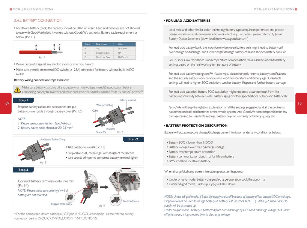
16 OTHERS OTHERS AC Output Data (On-grid) ominal Power Output to Grid (W) Max. Apparent Power Output to Grid(VA) Max. Apparent Power From Grid(VA) ominal Output Voltage (V) ominal Output Frequency (Hz) Max. AC Output Current to Grid (A) [7] Max. AC Current from Grid (A) [8] AC Back-feed Current (A) Max. Output Fault Current (Peak/Duration) Output Inrush Current (Peak/Duration) Input Inrush Current (Peak/Duration) Output Power Factor Output THDi Output) AC Overvoltage Category Efficiency Max. Efficiency GW3648D-ES ~1(Adjustable from 0.8 leading to 0.8 agging) GW5048D-ES [6] GW5048D-ES:4600 for VDE-AR-4105, 4950 for AS4777.2; GW3648D-ES: 4050 for CEI 0-21 [7] 21.7A only for Australia and ew Zealand [8] GW5048D-ES 40A to inverter and backup, max 21.5A to inverter, GW3648D-ES:32A to inverter and backup, max 18A to inverter [9] Default communication with BMS is CA, requirment RS485 needs special configuration process 3% 97.6% Max. Battery to oad Efficiency 94.0% Europe Efficiency 97.0% MPPT Efficiency 99.9% General Data Operation Temperature Range ( ) -25~60 Storage Temperature Range ( ) Relative Humidity Moisture ocation Category 0~95% 4K4H External Environment Pollute Degree Grade 1,2,3 Environment Category Outdoor & Indoor Operation Altitude (m) 4000 R, X for eutral conductor 27 Cooling system ature Convection 28 oise (db) User Interface Communication With BMS [9] Communication With EzMeter Communication With Portal 25 ED, APP CA, RS485 RS485 Weight (kg) Wi-Fi Size (Width*Height*Depth mm) 516*440*184 Mounting IP Rating Protective Class Standby Self-Consumption (W) Topology / A, 0.2s 55A, 5µs 60A, 3µs -30~65 Wall Bracket IP65 13 High Frequency Isolation / A, 0.2s 55A, 5µs 60A, 3µs Protection Anti-islanding Protection PV String Input Polarity Reverse Protection Isolation Resistor Detection Residual Current Monitoring Unit Output Over-current Protection Output Short Protection Output Over-voltage Protection Certifications & Standards Grid Regulation Safety Regulation EMC CERTIFICATES OF ES SERIES G83 G59 G100 IEC CEI 0-21 RD1699 VDE VDE-AR RS OTHER TEST For Australian requirements, in the THDi test, there should add Zref between inverter and mains. RA, XA for ine conductor Zref: RA=0,24;XA=j0,15 at 50Hz; R=0,16;X=j0,10 at 50Hz. 4.4 WARIIG QUICK CHECK IST GW3648D-ES Integrated (AFD) Integrated Integrated Integrated Integrated Integrated Integrated AS/ZS :2015, G83/2, G100, CEI 0-21, VDE4105-AR-, VDE , RS IEC/E & -2, IEC E , E , E , E , E , E , E GW5048D-ES AS/ZS :2015, G59/3, G100, CEI 0-21, VDE4105-AR-, VDE , RS [1] Inverter cannot be installed near flammable, explosive or strong electro-magnetic equipment, page 06 [2] Remember that this inverter is heavy! Please be careful when lifting out from the package, page 07 [3] The polarity of PV strings or on the inverter cannot be connected by reverse, otherwise inverter could be damaged, page 08 [4] Make sure battery switch is off and battery nominal voltage meet ES specification before connecting battery to inverter and make sure inverter is totally isolated from PV and AC power, page 09 [5] Make sure inverter is totally isolated from any DC or AC power before connectiong AC cable,page 11 [6] Make sure AC cable is totally isolated from AC power before connecting EzMeter and CT,page 13
17 OTHERS OTHERS Appendix: Protection Category Definition Overvoltage Category Definition Category Applies to equipment connected to a circuit where measures have been taken to reduce transient overvoltage to a low level Category Applies to equipment not permanently connected to the installation. Examples are appliances, portables tools and other plug-connected equipment Category Applies to a fixed equipment downstream of and including the main distribution board. Examples are switchgear and other equipment in an industrial installation Category Applies to equipment permanently connected at the origin of an installation (upstream of the main distribution board). Example are electricity meters, primary over-current protection equipment and other equipment connected directly to outdoor open lines Moisture ocation Category Definition Moisture Parameters evel 3K3 4K2 4K4H Temperature Range 0~+40-33~+40-20~+55 Humidity Range 5%~85% 15%~100% 4%~100% Environment Category Definition Environment Condition Ambient Temperature Relative Humidity Applied to 29 Outdoor -20 ~ 50 4% ~ 100% PD3 Indoor Unconditioned -20 ~ 50 5% ~ 95% PD3 Indoor Conditioned 0 ~ 40 5% ~ 85% PD2 Pollution Degree Definition Pollution Degree o pollution or only dry, non-conductive pollution occurs. The pollution has no influence Pollution Degree ormally only non-conductive pollution occurs. Occasionally, however, a temporary conductivity caused by condensation must be expected. Pollution Degree Conductive pollution occurs, or dry, non-conductive pollution occurs, which becomes conductive due to condensation, which is expected. Pollution Degree Persistent conductive pollution occurs, for example, the pollution caused by conductive dust, rain and snow.
ES SERIES USER MANUAL
 Official Website APP (ios) APP (Android) 340-00004-03 Version: 1.0 Jiangsu GoodWe Power Supply Technology Co.,td o.189 Kun un Shan Road, SD, Jiangsu, China. www.goodwe.com service@goodwe.com ES SERIES
SBP SERIES USER MANUAL
 APP (ios) APP (Android) 340-00087-02 Version: 1.0 Official Website Jiangsu GoodWe Power Supply Technology Co.,td www.goodwe.com SBP SERIES USER MAUA service@goodwe.com AC-COUD BATTERY STORAGE RETROFIT o.189
Franciscusdreef 42C 3565AC Utrecht
 ios App Store Google play Franciscusdreef 42C 3565AC Utrecht 340-00053-00 4.6 4.7 4.8 DRED Connection 4.9 Earth Fault Alarm 4.10 13 14 14 14 4.12 special backup application 15 15 6 CEI Auto Test introduction
PV Master OPERATION MANUAL
 PV Master OPERATION MANUAL GoodWe Technical Services Center December, 2017 Ver. 1.00 BRIEF INTRODUCTION PV Master is an external application for GoodWe inverters to monitor or configure inverters or to
Power Whenever You Need
 Power Whenever You Need Residential Energy Storage Solutions Hybrid Inverter ES Series EM Series Technical Data GW3648D-ES GW5048D-ES GW3048-EM GW3648-EM GW5048-EM Battery Input Data Battery Type Li-Ion
Introduction of EzManage Application
 Introduction of EzManage Application GoodWe Technical Services Center Dec 20, 2016 BRIEF INTRODUCTION EzManage is an external monitoring/ configuration application for GoodWe hybrid inverters, used on
Catch Eco Range : Technical Specification Sheet
 Catch Eco Range : Technical Specification Sheet Battery Hybrid Inverter AC Coupled Inverter Lithium phosphate technology High cycle life with warrantied throughput Indoor and outdoor options (IP21 and
S-BP SERIES USER MANUAL
 ios App Store Google Play S-BP SERIES USER MANUAL AC-COUPLED INVERTER enquiries@goodwe.co.uk 340-00087-0 .3 Special illustration 03 05 06 06 07 4. 4.3 4.4 4.5 4.6 DRED Connection 4.7 Earth Fault Alarm
Power Whenever You Need
 Power Whenever You Need Residential Energy Storage Solutions Hybrid Inverter ES Series EM Series Technical Data GW3648D-ES GW5048D-ES GW3048-EM GW3648-EM GW5048-EM Battery Input Data Battery Type Li-Ion
Manual. BlueSolar Grid Inverter 1500 / / / / / 230
 Manual EN BlueSolar Grid Inverter 1500 / 230 2000 / 230 2800 / 230 4000 / 230 5000 / 230 Before you start This manual contains important information regarding installation and safe operation of this unit.
EM QUICK INSTALLATION INSTRUCTIONS
 QR ode or ndriod System QR ode or ios System M QUIK ISTTI ISTRUTIS PRT PRT PRT QUIK ISTTI TTRY TI Wi-i IURTI 0-000-0 Step. Instructions or Quick Installation Step. Wi-i onfiguration Instruction Step. Instructions
Goodwe 5048ES with BYD B-BOX (2.5-10) Installation Guide
 Installation Guide") Goodwe 5048ES with BYD B-BOX (2.5-10) Installation Guide Attention: Goodwe 5048D-ES in this manual is the new one with serial number starting with 9 ie 95048ESU16XXXXX. For the Goodwe 5048D-ES with starting
Goodwe 5048ES with BYD B-BOX (2.5-10) Installation Guide Attention: Goodwe 5048D-ES in this manual is the new one with serial number starting with 9 ie 95048ESU16XXXXX. For the Goodwe 5048D-ES with starting
BYD Battery-Box LV Installation Guidance
 Battery-Box L 3.5/7.0/10.5/14.0 Version1.0 1 / 33 Contents 1 SAFETY... 6 2 PRODUCT OVERVIEW... 7 3 BCU INTRODUCTION... 7 4 DESCRIPTION OF B-PLUS L 3.5 INTERFACE AND TERMINAL... 8 5 PREPARATION... 9 5.1
Installing a Programmed Fronius SCERT in a Managed AC Coupled system
 Installing a Programmed Fronius SCERT in INTRODUCTION This document is included with Fronius SCERT PV Inverters that have been programmed. It applies only to units that have been programmed and are ready
BYD Battery-Box LV User Manual Battery-Box L 3.5/7.0/10.5/14.0
 BYD Battery-Box LV User Manual Battery-Box L 3.5/7.0/10.5/14.0 Version 0.1 BYD Battery-Box LV User Manual Contents 1 General Information... 3 1.1 Validity... 3 1.2 Application... 3 1.3 Intended use...
TECHNICAL SPECIFICATION FOR ENERGY STORAGE SYSTEM REV 6.0
 TECHNICAL SPECIFICATION FOR ENERGY STORAGE SYSTEM Product Name Power Pillar SG Reviewed by: Liu Weiwei Draft by Zhang Guanqun REV 6.0 Contents 1. Generality... 2 2. Product Model Description... 2 3. Equipment
BP SERIES USER MANUAL
 ios App Store Android market BP SERIES USER MANUAL Global Service Hotline:400-998-1212 GoodWe(China) No.189 Kunlunshan Rd., SND, Suzhou, 215163, China T: +86 512 6239 6791(service) service.chn@goodwe.com.cn
All-in-one Storage Hybrid System
 All-in-one Storage Hybrid System The priority of power supply for battery and AC can be settable; There is no gap to switch between on-grid and off-grid in 0ms,and it will never go offline; Efficient Built-in
8 Troubleshooting and Maintenance
 8 Troubleshooting and Maintenance 8.1 Troubleshooting 8.1.1 Troubleshooting of LED Indicators See Tab. 7-4 State Descriptions of LED Indicators for the definition. Fault Type LED indicators and LCD screen
T Series (N6052T) Solar Battery Hybrid System. Installation Manual Version 1.1
 Solar Battery Hybrid System. Installation Manual Version 1.1") T Series (N6052T) Solar Battery Hybrid System Installation Manual Version 1.1 Content 1. Safety... 1 1.1 How to Use This Manual... 1 1.2 Safety Rules... 1 1.3 Warning Notices Affixed to the Device... 2
T Series (N6052T) Solar Battery Hybrid System Installation Manual Version 1.1 Content 1. Safety... 1 1.1 How to Use This Manual... 1 1.2 Safety Rules... 1 1.3 Warning Notices Affixed to the Device... 2
Dycon D1532SM. EN50131/PD6662 Grade 3, 12V 2A Power Supply. Technical Description Installation and Operating Manual DYCON POWER SOLUTIONS LTD
 Dycon D1532SM EN50131/PD6662 Grade 3, 12V 2A Power Supply Technical Description Installation and Operating Manual DYCON POWER SOLUTIONS LTD Tel: +44 (0)1443 471 900 Unit A Cwm Cynon Business Park Mountain
HANGKAI GROUP HOYMILES MICRO-INVERTER MI-250
 HANGKAI GROUP HOYMILES MICRO-INVERTER MI-250 TECHNICAL MANUAL CONTENTS INTRODUCTION... 3 SAFETY... 4 SYMBOL ILLUSTRATION... 4 INSTALLATION WARNINGS... 6 PREPARE FOR INSTALLING... 7 TRANSPORT AND INSPECT...
Residential Energy Storage System SH5K PV ESS
 www.sungrowpower.com Residential Energy Storage System SH5K PV ESS Why You Need the PV ESS (Energy Storage System)? In many countries, with the rising popularity of solar energy and its essential PV systems,
My Reserve 500 Install Guide
 My Reserve 500 Install Guide System Overview Diagram Warnings Disclaimer of Liability and Warranty: This guide does not replace the Owner s Guide and Installation Instructions supplied with the components.
ORVALDI Solar Infini 5kW
 ORVALDI Solar Infini 5kW User manual Version: 1.0 Table Of Contents 1. Introduction... 1 2. Important Safety Warning... 2 3. Unpacking & Overview... 4 4. Installation... 5 5. Grid (Utility) Connection...
c-go 24V/6A 24V/8A 24V/12A
 c-go 24V/6A 24V/8A 24V/12A Battery charger GB Instruction manual 1 Index 1. Product description... 2 2. Safety advices... 3 3. Quick start guide... 4 4. Operation... 4 5. Problem solving... 6 6. Specifications...
Residential Energy Storage System SH 5K
 www.sungrowpower.com Residential Energy Storage System SH 5K Why You Need the PV ESS (Energy Storage System)? In some countries with large-scale PV applications, such as Australia, with the rising popularity
OFF-GRID PV INVERTERS EssenSolar & Expert series. 1kW-5kW. Solution on Unstable or Remote Area without Utility
 OFF-GRID PV IVERTERS EssenSolar & Expert series Solution on Unstable or Remote Area without 1kW-5kW FSP Off-Gird Inverters: EssenSolar & Expert series An ideal Off-Grid inverter for households, FSP Off-Grid
User Manual. Hybrid 4KW PV Inverter. Version: 1.2
 User Manual Hybrid 4KW PV Inverter Version: 1.2 Table of Contents 1. Introduction... 1 2. Important Safety Warning... 2 3. Unpacking & Overview... 4 4. Installation... 5 4. Grid (Utility) Connection...
S-BP QUICK INSTALLATION INSTRUCTIONS
 QR ode or ndriod System QR ode or ios System S-P QUIK INSTLLTI INSTRUTIS 0-00088-0 PRT PRT PRT QUIK INSTLLTI TTRY NTI Wi-i IURTI Step. Instructions or Quick Installation Step. Wi-i onfiguration Instruction
String Inverter (SUN KTL-A)
") String Inverter (SUN2000-30KTL-A) Smart Maximum of 3 MPPT for versatile adaptions to different module types or quantities built up with different alignments 6 strings intelligent monitoring and 80% time
String Inverter (SUN2000-30KTL-A) Smart Maximum of 3 MPPT for versatile adaptions to different module types or quantities built up with different alignments 6 strings intelligent monitoring and 80% time
ABB PV + Storage REACT-3.6/4.6-TL 3.6 to 4.6 kw
 Solar inverters ABB PV + Storage REACT-3.6/4.6-TL 3.6 to 4.6 kw REACT stores and allows you to make the most of the energy produced by your photovoltaic system. REACT is an innovative photovoltaic inverter,
User Manual. Hybrid PV Inverter. Version: 2.1
 User Manual Hybrid PV Inverter Version: 2.1 Table Of Contents 1. Introduction...1 2. Important Safety Warning...2 3. Unpacking & Overview...4 3-1. Packing List... 4 3-2. Product Overview... 4 4. Installation...5
ABB PV + Storage REACT-3.6/4.6-TL 3.6 to 4.6 kw
 SOLAR INVERTERS ABB PV + Storage REACT-3.6/4.6-TL 3.6 to 4.6 kw REACT stores and allows to make the most of the energy produced by a residential photovoltaic system. 01 01 REACT-3.6/4.6-TL PV + Storage
BP SERIES USER MANUAL
 ios App Store Android market BP SERIES USER MANUAL GoodWe(China) No.189 Kunlunshan Rd., SND, Suzhou, 15163, China T: 400 998 11 service.chn@goodwe.com.cn www.goodwe.com.cn GoodWe(Australia) 19 Fairleigh
User Manual. SP10000 Premium
 User Manual Solar Hybrid 3Phase PV Inverter SP10000 Premium Version: 1.2 Table Of Contents 1. Introduction... 1 2. Important Safety Warning... 2 3. Unpacking & Overview... 4 3-1. Packing List... 4 3-2.
+86(571) (571) (V4)
 (571) (V4)") +86(571)-56260011 +86(571)-56075753 5 (V4) THE SOLAX INVERTER The solar inverter is a critical technological component that is the heart of any PV plant. A solar inverter or PV inverter, converts the variable
+86(571)-56260011 +86(571)-56075753 5 (V4) THE SOLAX INVERTER The solar inverter is a critical technological component that is the heart of any PV plant. A solar inverter or PV inverter, converts the variable
User Manual 1KVA-5KVA INVERTER / CHARGER
 User Manual 1KVA-5KVA INVERTER / CHARGER Version: 1.7 Table Of Contents ABOUT THIS MANUAL... 1 Purpose... 1 Scope... 1 SAFETY INSTRUCTIONS... 1 INTRODUCTION... 2 Features... 2 Basic System Architecture...
1. Introduction OHY1P kW Hybrid Inverter USER MANUAL V2.0
 1. Introduction OHY1P4805 5kW Hybrid Inverter USER MANUAL V2.0 1. Introduction Table of Contents 1. Introduction... 1 2. Important Safety Warning... 2 3. Unpacking & Overview... 4 4. Installation... 5
Installation and Operating Instructions. Solar System Controller ISC3020
 Installation and Operating Instructions Solar System Controller ISC3020 ABOUT THIS MANUAL These operating instructions come with the product and should be kept with it as a reference to all user s of
Nova UAC (NV-UAC-M) Modified Sine Wave 650W 800W 1000W
 Modified Sine Wave 650W 800W 1000W") ova UAC (V-UAC-M) Modified Sine Wave 650W 800W 1000W ISTRUCTIOS IMPORTAT SAFEGUARDS When using electrical equipment, basic safety precautions should always be followed including the following: 1. READ
ova UAC (V-UAC-M) Modified Sine Wave 650W 800W 1000W ISTRUCTIOS IMPORTAT SAFEGUARDS When using electrical equipment, basic safety precautions should always be followed including the following: 1. READ
GEatom306KHF-5U Three-phase Grid-Tied Battery Inverter. Version 1.1. Global Mainstream Dynamic Energy Technology Ltd. 1
 GEatom306KHF-5U Three-phase Grid-Tied Battery Inverter Version 1.1 Global Mainstream Dynamic Energy Technology Ltd. 1 Content Prelude... 4 1. Safety... 5 1.1 How to Use This Manual... 5 1.2 Safety Rules...
B-Box Pro 2.5~10.0 User Manual
 B-Box Professional user manual B-Box Pro 2.5~10.0 User Manual 20170323 Version: 2.2 Copyright BYD Company Limited. All rights reserved. Without the written consent of BYD Company, no entity or individual
Retrofit to Single phase / Three phase PV system Micro-grid, UPS, Peak shift, Pure off-grid retrofitting etc multi-working
 Retrofit to Single phase / Three phase PV system Micro-grid, UPS, Peak shift, Pure off-grid retrofitting etc multi-working mode for choice. Automatic, Zero Hybrid Switch Built-in Smart management control
MAKING MODERN LIVING POSSIBLE. UniLynx Indoor Installation Manual. ULX 1800i ULX 3000i ULX 3600i ULX 5400i SOLAR INVERTERS
 MAKING MODERN LIVING POSSIBLE UniLynx Indoor Installation Manual ULX 1800i ULX 3000i ULX 3600i ULX 5400i SOLAR INVERTERS Contents Contents 1. Introduction 2 Introduction 2 Installation Sequence 2 Important
User manual. Solar Hybrid 1-5KVA. Uninterruptible Power Supply / Charger
 User manual Solar Hybrid 1-5KVA Uninterruptible Power Supply / Charger All rights reserved. The information in this document is subject to change without notice. Thank you for purchasing this series UPS.
Dycon D2430 EN54-4 Fire Alarm Power Supply Series
 Dycon D2430 EN54-4 Fire Alarm Power Supply Series Technical Description Installation and Operating Manual Construction Product Regulation 0359-CPR-00434 Page 1 of 14 Contents 1. General... 3 1.1 Product
c-go 12V/10A 12V/20A Power supply and battery charger Instruction manual
 c-go 12V/10A 12V/20A Power supply and battery charger GB Instruction manual 1 Index 1. Product description... 2 2. Safety advices... 3 3. Mounting and installation... 4 4. Operation... 5 5. Problem solving...
Installation and Operating Instructions. MPPT Solar System Controller ISC3040
 Installation and Operating Instructions MPPT Solar System Controller ISC3040 ABOUT THIS MANUAL These operating instructions come with the product and should be kept with it as a reference to all user s
GOODWE & PYLONTECH ENERGY STORAGE
 GOODWE & PYLONTECH ENERGY STORAGE 1 About Goodwe Product Review Goodwe Competitive Advantage Pylontech batteries 2 About GoodWe Focus on developing and producing solar inverters and monitoring products.
Phoenix Inverter
 Manual EN Handleiding NL Manuel FR Anleitung DE Manual ES Appendix Phoenix Inverter 12 250 12 375 12 500 12 800 24 250 24 375 24 500 24 800 48 250 48 375 48 500 48 800 1. Safety instructions WARNING: ELECTRIC
Technical specifications
 xstorage Home Technical specifications System overview The following Table 1 provides a general overview of battery capacity and inverter power range combinations that can be integrated together with the
CPS Energy Balancer. Version: 1.0
 CPS Energy Balancer Version: 1.0 CHINT POWER SYSTEMS AMERICA CO., LTD. Address: 700 International Parkway, Suite 102 Richardson, Texas Zip Code: 75081 Web: www.chintpower.com/na Email: americasales@chintpower.com
BYD Battery-Box Pro User Manual Battery-Box Pro 13.8
 Battery-Box Pro 13.8 Version 4.0 Contents 1 General Information... 3 1.1 Validity... 3 1.2 Application... 3 1.3 Intended use... 3 1.4 Battery-Box definition... 3 1.5 Identifying the Product... 3 2 Safety...
User Manual. 3kW Hybrid PV Inverter HX-3000
 User Manual 3kW Hybrid PV Inverter HX-3000 Table Of Contents 1. Introduction...1 2. Important Safety Warning...2 3. Unpacking & Overview...4 3-1. Packing List... 4 3-2. Product Overview... 4 4. Installation...5
User Manual 1KVA/ 2KVA/ 3KVA INVERTER / CHARGER
 User Manual 1KVA/ 2KVA/ 3KVA INVERTER / CHARGER CONTENTS ABOUT THIS MANUAL... 1 Purpose... 1 Scope... 1 SAFETY INSTRUCTIONS... 1 INTRODUCTION... 2 Features... 2 Basic System Architecture... 2 Product Overview...
SolarMax MT series. The power pack for maximum yields.
 SolarMax MT series The power pack for maximum yields. All good things come in three phases. We have been developing and producing transformerless inverters for over 20 years. Our engineers have effectively
SMT. Installation and Operation Manual. Model:SMT WITH MPPT TECHNOLOGY
 SMT WITH MPPT TECHNOLOGY Installation and Operation Manual Model:SMT SMT Dimensions Specification Summary System Voltage 12 V/24V Rated Battery Current 12V, 5A 8A 10A 15A 20A 25A 24V, 5A 8A 10A 15A Rated
Installation and Operating Instructions. Solar System Controller ISC3030
 Installation and Operating Instructions Solar System Controller ISC3030 ABOUT THIS MANUAL These operating instructions come with the product and should be kept with it as a reference to all user s of the
BYD Battery-Box HV User Manual Battery-Box H 5.1/6.4/7.7/9.0/10.2/11.5
 Battery-Box H 5.1/6.4/7.7/9.0/10.2/11.5 Version 5.0 Contents 1 General Information... 2 1.1 Validity... 2 1.2 Application... 2 1.3 Intended Use... 2 1.4 Definition... 2 1.5 Identifying The Product... 3
User Manual. Solar Charge Controller 3KW
 User Manual Solar Charge Controller 3KW 1 CONTENTS 1 ABOUT THIS MANUAL... 3 1.1 Purpose... 3 1.2 Scope... 3 1.3 SAFETY INSTRUCTIONS... 3 2 INTRODUCTION... 4 2.1 Features... 4 2.2 Product Overview... 5
Get ready for rising energy challenges. This is where xstorage Home can help
 xstorage Home Get ready for rising energy challenges More and more people, factories, businesses connect to the grid around the world. How can you be sure there will still be power for you and your family
Pre-announcement. Transformerless Solar Inverters
 Pre-announcement Transformerless Solar Inverters Content About us 2 SOLIVIA - Solar inverters without transformer 4 Solar inverters for residential installations 6 SOLIVIA 3.0 TL 8 SOLIVIA 5.0 TL 10 Solar
Off Grid Solar Inverter. LVS 50M User Manual
 Off Grid Solar Inverter LVS 50M User Manual Save This Manual Please read this manual carefully prior to installation, wiring, operation and maintenance of the LVS M Series. This manual contains important
OHY3P kW Hybrid Inverter (3-Phase) USER MANUAL V2.0
 USER MANUAL V2.0") OHY3P4810 10kW Hybrid Inverter (3-Phase) USER MANUAL V2.0 Table of Contents 1. Introduction... 1 2. Important Safety Warning... 2 3. Unpacking & Overview... 4 3-1. Packing List... 4 3-2. Product Overview...
OHY3P4810 10kW Hybrid Inverter (3-Phase) USER MANUAL V2.0 Table of Contents 1. Introduction... 1 2. Important Safety Warning... 2 3. Unpacking & Overview... 4 3-1. Packing List... 4 3-2. Product Overview...
PowerLegato User Operation Guide
 PowerLegato User Operation Guide Residential Energy Storage System Table Of Contents SAFETY INFORMATION Please read all instructions and cautions before using PowerLegato. 1. Safety and Cautions 2. PowerLegato
STONESTAR AUSTRALIA PTY LTD
 42 48 REDWOOD DRIVER,DINGLEY VIC3172,AUSTRALIA TEL:0061 3 95518393 FAX:0061 3 95580776 EMAIL:stonestar@ssawheels.com.au Contents 1. Product Introduction... 3 2. Installation... 5 1) Safety instructions...
USER MANUAL. IPS home inverters with UPS function. IPS home inverter manual
 USER MANUAL IPS home inverters with UPS function Suitable for UPS: - IPS300-SIN - IPS300-SIN-WM - IPS300-SIN-DC - IPS600-SIN - IPS600-SIN-WM - IPS600-SIN-DC - IPS1000-SIN - IPS1000-SIN-DC - IPS1600-SIN
Lesson 4 Configuring the system. copy right reserved by GoodWe
 51 3. Run the APP EzManage. 4. Series Selection Page: When the APP is first used, it will pair with the inverter automatically when connecting to the inverter s WiFi. If the APP stays at the series selection
Multi Wheel Bluetooth Tire Pressure Monitoring System User Manual Model: External
 T P M S Multi Wheel Bluetooth Tire Pressure Monitoring System User Manual Model: External Table of Contents 1. PRODUCT INTRODUCTION... 2 2. NOTICE... 2 3. BLE TPMS SPECIFICATION... 3 4. BLE TPMS PACKAGE...
B-Box Pro 2.5~10.0 User Manual
 B-Box Professional user manual B-Box Pro 2.5~10.0 User Manual V2.2_July, 2017 Copyright BYD Company Limited. All rights reversed. Without the written consent of BYD Company, no entity or individual shall
MICRO-INVERTER OMNIKSOL M-300
 MICRO-INVERTER OMNIKSOL M-300 TECHNICAL MANUAL CONTENTS INTRODUCTION... 3 SAFETY... 4 SYMBOL ILLUSTRATION... 4 INSTALLATION WARNINGS... 6 PREPARE FOR INSTALLING... 7 TRANSPORT AND INSPECT... 7 CHECK INSTALLATION
YSmart Technology Co., Ltd. User Manual. GTI Grid Series. GTI Series Inverters for Grid-connected PV system
 YSmart Technology Co., Ltd. User Manual Contact Us Address: No. 30 XinFeng Road,Potoubei Village,Ailian Town,Longgang Dist, Shenzhen 51872,P.R. China Tel: (86)755-85232255 Fax: (86)755-85232255 Email :
i-energy i-micro inverter GT260
 i-energy i-micro inverter GT260 This installation guide contains important instructions on safety matters and the installation of the i-energy i-micro inverter GT260. Please read this guide carefully and
PV Generation System. Solar Charge Controller SPECIFICATION
 PV Generation System Solar Charge Controller SPECIFICATION Home application type Version: V5.0 Thank you very much for selecting our product! This manual offers important information and suggestions with
SH5K+ Hybrid Inverter Overview & Installation.
 SH5K+ Hybrid Inverter Overview & Installation www.sungrowpower.com 01 SH5K+ www.sungrowpower.com 2 Router SolarInfo Moni SolarInfo Server SolarInfo Bank ü Sungrow Samsung ü LG Chem ü GCL ü ZTE Pylon www.sungrowpower.com
Smart Hybrid Solar Inverter System
 Installation and operators manual Smart Hybrid Solar Inverter System Grid-tie Solar Inverter System with utility backup AC output and energy storage capability Contact information: Redback Technologies
T P M S. Multi Wheel Bluetooth. Tire Pressure Monitoring System. User Manual. Model: External
 T P M S Multi Wheel Bluetooth Tire Pressure Monitoring System User Manual Model: External Table of Contents 1. PRODUCT INTRODUCTION... 2 2. NOTICE... 2 3. BLE TPMS SPECIFICATION... 3 4. BLE TPMS PACKAGE...
USER S MANUAL SOLAR POWER INVERTER KW-6KW
 USER S MANUAL ------SOLAR POWER INVERTER------ 1KW-6KW Appliances--------------------------------------------- Content Content Content... 1 1 Figures of unit... 2 2 Specification... 3 3 Front panel...
/ The personal storage solution for 24H sun. / Dynamic Peak Manager. / Smart Grid Ready THREE-PHASE
 Perfect Welding Solar Energy Perfect Charging FRONIUS ENERGY PACKAGE The personal storage solution for 24H sun. PC board replacement process SnapINverter technology Integrated data communication Dynamic
User Manual 1.5KVA-3KVA INVERTER / CHARGER. Version: 1.1
 User Manual 1.5KVA-3KVA INVERTER / CHARGER Version: 1.1 Table Of Contents ABOUT THIS MANUAL... 1 Purpose... 1 Scope... 1 SAFETY INSTRUCTIONS... 1 INTRODUCTION... 2 Features... 2 Basic System Architecture...
PowerRouter Solar Battery Self-use
 PowerRouter Solar Battery Self-use the PowerRouter > Generate your own energy from solar energy > Store self-generated energy > Use stored energy > Save on energy costs > Monitoring and management via
HYBRID 5048E. Hybrid Inverter INSTALLATION AND OPERATION MANUAL. Version 2.0E
 HYBRID 5048E Hybrid Inverter INSTALLATION AND OPERATION MANUAL Version 2.0E SAFETY INSTRUCTIONS Risk of Electric Shock Alternating Current (AC) and Direct Current (DC) sources are connected to this device.
& Operation Manual. Growatt 10000HY. Installation GR-UM-A03-A-00
 Growatt 10000HY Installation & Operation Manual GROWATT NEW ENERGY TECHNOLOGY Co.,LTD No.28 Guangming Road, Shiyan, Baoan District, Shenzhen, P.R. China T F E W + 86 755 2747 1900 + 86 755 2747 2131 info@ginverter.com
User Manual 3KVA/5KVA 24V INVERTER / CHARGER. Version: 1.1
 User Manual 3KVA/5KVA 24V IVERTER / CHARGER Version: 1.1 Table Of Contents ABOUT THIS MAUAL... 1 Purpose... 1 Scope... 1 SAFETY ISTRUCTIOS... 1 ITRODUCTIO... 2 Features... 2 Basic System Architecture...
User Manual V1.1 OptiFlex 1100 / OptiFlex 2000
 User Manual V1.1 OptiFlex 1100 / OptiFlex 2000 Uninterruptible Power Supply System Table of Contents 1. Important Safety Warning 2 1-1. Transportation 2 1-2. Preparation 2 1-3. Installation 2 1-4. Operation
w w w.apc.com Home Appliance & Lighting UPS HI800SQ Installation Guide and User s Manual
 w w w.apc.com Home Appliance & ighting UPS HI800SQ Installation Guide and User s Manual 990-2391D Copyright 2009 American Power Conversion. All rights reserved. APC is a registered trademark of American
Growatt Storage Plus. Marketing Dept. Aug 2014
 Growatt Storage Plus Marketing Dept. Aug 2014 Growatt SP 2000 Features: Charge power Dimension (W X H X D) Weight 2000W 520*340*160 mm 12 kg (without batteries) >> For more details Warranty 5 Years Lifetime
User Manual Solar Charge Controller 3KW
 User Manual Solar Charge Controller 3KW Version: 1.3 CONTENTS 1 ABOUT THIS MANUAL... 1 1.1 Purpose... 1 1.2 Scope... 1 1.3 SAFETY INSTRUCTIONS... 1 2 INTRODUCTION... 2 2.1 Features... 2 2.2 Product Overview...
Eguana Evolve. Installation & Start-up Guide. Grid Support Utility Interactive Inverter & Integrated Lithium Battery.
 Eguana Evolve Model Evolve 0513 Grid Support Utility Interactive Inverter & Integrated Lithium Battery Installation & Start-up Guide For use only with battery model LG Chem EM048126P3S7 DO 68-003 Publish
B-Box Pro 13.8 User Manual
 B-Box Professional user manual B-Box Pro 13.8 User Manual Rev 1.0_July.2017 Copyright BYD Company Limited. All rights reversed. Without the written consent of BYD Company, any entity or individual shall
User Manual. NetGuard IMPORTANT. PSD 650/1200/1600 Line Interactive UPS Uninterruptible Power Supply System. UPS Monitoring Software
 User Manual Thank you for purchasing the Defender 650/1200/1600. It is designed to provide safe and reliable power protection to your precious electronics equipment. Before you start using the product,
SolarMax MT series The all-rounder for trade and industry
 SolarMax MT series The all-rounder for trade and industry All good things come in three phases. We have been developing and producing transformerless inverters for over 20 years. Our engineers have effectively
IES GRID FEED-IN LIMITER
 IES GRID FEED-IN LIMITER Installation and User Manual Models SPS01101-ABB SPS01303-ABB CONTAINS IMPORTANT INSTALLATION AND TESTING PROCEDURES THAT MUST BE FOLLOWED TO ENSURE COMPLIANCE WITH ENERGEX AND
HOYMILES MICRO-IVERTER MI-250
 HOYMILES MICRO-IVERTER MI-250 TECHNICAL MANUAL CONTENTS INTRODUCTION... 3 SAFETY... 4 SYMBOL ILLUSTRATION... 4 INSTALLATION WARNINGS... 5 PREPARE FOR INSTALLING... 6 TRANSPORT AND INSPECT... 6 CHECK INSTALLATION
User Manual Rittal PMC UPS 6kVA
 User Manual Rittal PMC UPS 6kVA Germany Rittal GmbH & Co. KG Auf dem Stützelberg D-35745 Herborn Tel.: ++49-27 72-5 05-0 Fax: ++49-27 72-5 05-23 19 Internet: www.rittal.de 26 Contents 1. Introduction...
User Manual. PF0.9 1K/2K/3K Online UPS. Uninterruptible Power Supply System. Version: 1.3
 User Manual PF0.9 1K/2K/3K Online UPS Uninterruptible Power Supply System Version: 1.3 Table of Contents 1. Important Safety Warning... 1 1-1. Transportation... 1 1-2. Preparation... 1 1-3. Installation...
Manual. EN Appendix. Lynx Ion BMS 400A / 1000A
 Manual EN Appendix Lynx Ion BMS 400A / 1000A 1. SAFETY INSTRUCTIONS 1.1 In general Please read the documentation supplied with this product first, so that you are familiar with the safety signs en directions
DUAL/TRIPLE MPPT INVERTER / CHARGER. User Manual
 DUAL/TRIPLE MPPT IVERTER / CHARGER User Manual Table Of Contents ABOUT THIS MAUAL... 1 Purpose... 1 Scope... 1 SAFETY ISTRUCTIOS... 1 ITRODUCTIO... 2 Features... 2 Basic System Architecture... 2 Product
User Manual 1.5KVA-3KVA INVERTER / CHARGER
 User Manual 1.5KVA-3KVA INVERTER / CHARGER Version: 1.0 Table Of Contents ABOUT THIS MANUAL... 1 Purpose... 1 Scope... 1 SAFETY INSTRUCTIONS... 1 INTRODUCTION... 2 Features... 2 Basic System Architecture...