HOYMILES MICRO-IVERTER MI-250
|
|
|
- Shavonne Madison Ward
- 5 years ago
- Views:
Transcription

1 HOYMILES MICRO-IVERTER MI-250
2 TECHNICAL MANUAL CONTENTS INTRODUCTION... 3 SAFETY... 4 SYMBOL ILLUSTRATION... 4 INSTALLATION WARNINGS... 5 PREPARE FOR INSTALLING... 6 TRANSPORT AND INSPECT... 6 CHECK INSTALLATION ENVIRONMENT... 7 INSTALLATION POSITION... 7 MOUNTING AND WIRING... 8 INSTALLING DIAGRAM... 8 ASSEMBLY INSTRUCTION... 9 Step 1. Install Micro-inverter... 9 Step 2. Connect AC Cable of Micro-inverter... 9 Step 3. Protecting Unused Ends... 9 Step 4. Connecting AC-TRUNK Cables to Junction Box Step 5. Drawing System Map Step 6. Install Photovoltaic Modules Step 7. Install CDD MAINTENANCE GUIDE ROUTINE MAINTENANCE STORAGE AND DISMANTLING APPENDIX TECHNICAL DATA EFFICIENCY CURVES... 错误! 未定义书签 TEMPLATE FOR MAP OF MICRO-INVERTER INSTALLATION... 16
3 INTRODUCTION Thank you for using MI-250 Micro-Inverter! This Micro-Inverter system is the world s most technologically advanced inverter system with benefits of efficient, flexible, safe and reliable for use in utility-interactive applications. This system is composed of a group of Micro-inverters that convert direct current (DC) into alternating current (AC) and feeds it into the electric grid. Different from systems that photovoltaic modules are subdivided into strings and controlled by one or several inverters, this system is built for the incorporation of a Micro-inverter for each photovoltaic module. Each Micro-inverter works independently of the others to guarantee maximum power of each photovoltaic module. This setup enables direct control over the production of a single photovoltaic module, consequently improving the flexibility and reliability of the system. This manual contains important instructions for the MI-250 Micro-inverter and must be read in its entirety before installing or commissioning the equipment. For safety, only qualified technician, who has received training or has demonstrated skills can install and maintain this Micro-inverter under the guide of this document. There are two models of the Micro-inverter, delineated by the maximum output power. This document applies only to the inverter models listed in Table 1 below: Table 1 Output Power 250W 500W Model Number MI-250 MI-500 Hoymiles can provide commissioning. Please contact Hoymiles customer service at More information at website:
4 SAFETY IMPORTANT SAFETY INSTRUCTIONS! PLEASE KEEP THIS INTRODUCTION IN A SAFE PLACE! SYMBOL ILLUSTRATION The safety symbols used in this manual are list below and illustrated in detail. Symbol Usage Indicates a hazardous situation that can result in deadly electric shock hazards, other serious physical injury, or fire hazards. Indicates directions which must be fully understood and followed in entirety in order to avoid potential safety hazards including equipment damage or personal injury. This points out that the described operation must not be carried out. The reader should stop, use caution and fully understand the operations explained before proceeding.
5 INSTALLATION WARNINGS The MI-250/500 Micro-inverter is designed and tested according to international safety requirements (IEC /2; VDE4105/0126). However, certain safety precautions must be taken when installing and operating this inverter. The installer must read and follow all instructions, cautions and warnings in this installation manual All operations including transport, installation, start-up and maintenance, must be carried out by qualified, trained personnel. Before installation, check the unit to ensure absence of any transport or handling damage, which could affect insulation integrity or safety clearances. Choose installation location carefully and adhere to specified cooling requirements. Unauthorized removal of necessary protections, improper use, incorrect installation and operation may lead to serious safety and shock hazards or equipment damage. Before connecting the Micro-inverter to the power distribution grid, contact the local power distribution grid company to get appropriate approvals. This connection must be made only by qualified technical personnel. It is the responsibility of the installer to provide external disconnect switches and Overcurrent Protection Devices (OCPD). Only one photovoltaic module can be connected in the input of the inverter. Do not connect batteries or other sources of power supply. The inverter can be used only if all the technical characteristics are observed and applied. Do not install the equipment in adverse environment conditions such as flammable, explosive, corrosive, extreme high or low temperature, and humid. Do not use the equipment when the safety devices do not work or disabled. Use personal protective equipment, including gloves and eye protection when working. Inform the manufacturer about non-standard installation conditions. Do not use the equipment if any operating anomalies are found. Avoid temporary repairs. All repairs should be carried out using only qualified spare parts, which must be installed in accordance with their intended use and by a licensed contractor or authorized Hoymiles service representative. Liabilities arising from commercial components are delegated to their respective manufacturers. Anytime the inverter has been disconnected from the power network, use extreme caution as some components can retain charge sufficient to create a shock hazard. Prior to touching any part of the inverter use care to ensure surfaces and equipment are at touch safe temperatures and voltage potentials before proceeding. Hoymiles accepts No liability for damage from incorrect or careless operation
 from violent, shocks, humidity,")
6 PREPARE FOR INSTALLING TRANSPORT AND INSPECT Hoymiles packages and protects individual components using suitable means to make the transport and subsequent handling easier. Transportation of the equipment, especially by road, must be carried out by suitable ways for protecting the components (in particular, the electronic components) from violent, shocks, humidity, vibration, etc. Please dispose the packaging elements in appropriate ways to avoid unforeseen injury. It is the customer s responsibility to examine the condition of the components transported. Once receiving the Micro-inverter, it is necessary to check the container for any external damage and verify receipt of all items. Call the delivering carrier immediately if damage or shortage is detected. If inspection reveals damage to the inverter, contact the supplier, or authorized distributor for a repair/return determination and instructions regarding the process. Components supplied by Hoymiles are list in Table 2 below: Table 2 Code Description AC trunk end cap End cap for 10 AWG AC cable
7 CHECK INSTALLATION ENVIRONMENT Installation of the equipment is carried out based on the system design and the place in which the equipment is installed. The installation must be carried out with the equipment disconnected from the grid (power disconnect switch open) and with the photovoltaic modules shaded or isolated. See Appendix: Technical Data to check the environmental parameters to be observed (degree of protection, temperature, humidity, altitude, etc.) To avoid unwanted power derating due to an increase in the internal temperature of the inverter, do not expose it to direct sunlight. To avoid overheating, always make sure the flow of air around the inverter is not blocked. Do not install in places where gasses or flammable substances may be present. Avoid electromagnetic interference that can compromise the correct operation of electronic equipment. INSTALLATION POSITION When choosing the position of installation, comply with the following conditions: Install only on structures specifically conceived for photovoltaic modules (supplied by installation technicians). Install Micro-inverter underneath the photovoltaic modules so that they work in the shade. If this condition cannot be met, the inverter could undergo derating. PV Module Micro Inverter Fig.1. Installation position of Micro-inverter
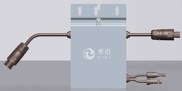
8 MOUNTING AND WIRING INSTALLING DIAGRAM System Schematic Diagram AC Distribution Panel Red:Live Black:Neutral Green:Ground Junction Box PV Module DC AC Micro inverter AC Cable DC AC Fig Vac single phase Assembly Diagram PV Module AC End Cap Bracket AC Cable DC Cables From Micro Inverter PV Module Junction Box Fig.3. Assembly Illustration


9 ASSEMBLY INSTRUCTION Step 1. Install Micro-inverter Mark the approximate center of each photovoltaic module on the frame and install the Micro-inverter with the logo side facing downwards. Observe the certification documents concerning the maximum number of Micro- inverters permitted for installation at each cable section! The Micro-inverter must be under the module, out of long-term exposure to direct sunlight or rain. Step 2. Connect AC Cable of Micro-inverter Connect the AC cable of the Micro-inverters. The connectors are coupled correctly when two clicks are heard. Step 3. Protecting Unused Ends Fig.4. Connect AC Cable of Micro-inverter The unused ends of the AC-TRUNK cable must be terminated with the proper end. Fit the appropriate AC-TRUNK END CAP on the unused ends of the AC-TRUNK cable. AC End Cap Fig.5. Unused Ends
10 Step 4. Connecting AC-TRUNK Cables to Junction Box Connect the AC-TRUNK cables coming from the MICRO inverters to the junction box. Close the junction box after the wiring is complete. Ensure that the seal is tight. Fig.6. Junction Box To prevent electrical hazards, all the connection operations must be carried out with the equipment disconnected from the grid. All the external connections to the insulated junction box (caps, adapters, etc.) must be made with securely-sealed Hoymiles components.
11 Hoymiles AC cables from the Micro-inverters have three conductors with different colors to identify the function of each conductor: Red: Live Black: Neutral Yellow-Green: Ground Pay special attention and ensure not to reverse the phase with the neutral! The installation technician is responsible for selecting a junction box with the appropriate dimensions and insulation. The installation technician is responsible for selecting a cable running between the junction box and the load distribution panel with the appropriate length and cross section. Step 5. Drawing System Map Draw a map of the system, affixing the extra label that comes attached to each inverter, on the appropriate position on the diagram (found in the Appendix of this manual). Fig.7. System Map Step 6. Install Photovoltaic Modules Install the photovoltaic modules, and connect the DC cables of the modules to the corresponding DC input side of the Micro-inverter.
12 DC Cable From PV Module DC Cable From Micro Inverter Fig.8. Connect DC Cables The recommended installation need keeping the Micro-inverters underneath the photovoltaic modules, so that the Micro-inverters can operate in the shade. Direct sunlight may cause damage to the Micro-inverters. Each module must be connected to the Micro-inverters with a DC cable having a length of less than 3m. Step 7. Install CDD Install the CDD (Concentrator Data Device) and commission
13 MAINTENANCE GUIDE ROUTINE MAINTENANCE Only authorized personnel are allowed to carry out the maintenance operations and are responsible to report any anomalies. Always use the personal protective equipment provided by the employer when carry out the maintenance operation. During normal operation, check that the environmental and logistic conditions are correct. Make sure that the conditions have not changed over time and that the equipment is not exposed to adverse weather conditions and has not been covered with foreign bodies. DO NOT use the equipment if any problems are found, and restore the normal conditions after the fault removed. Conduct an annual inspection on various components, and clean the equipment with a vacuum cleaner or special brushes. Do not attempt to dismantle the Micro-inverter or make any internal repairs! In order to preserving the integrity of safety and insulation, the Micro-inverters are not designed to allow internal repairs! The AC output wiring harness (AC drop cable on the Micro- inverter) cannot be replaced. If the cord is damaged the equipment should be scrapped. Maintenance operations must be carried out with the equipment disconnected from the grid (power switch open) and the photovoltaic modules obscured or isolated, unless otherwise indicated. For cleaning, DO NOT use rags made of filamentary material or corrosive products that may corrode parts of the equipment or generate electrostatic charges. Avoid temporary repairs. All repairs should be carried out using only genuine spare parts.
14 STORAGE AND DISMANTLING If the equipment is not used immediately or is stored for long periods, check that it is correctly packed. The equipment must be stored in well-ventilated indoor areas that do not have characteristics that might damage the components of the equipment. Take a complete inspection when restarting after a long time or prolonged stop. Please dispose the equipment properly after scrapping, which are potentially harmful to the environment, in accordance with the regulations in force in the country of installation.
15 APPENDIX TECHNICAL DATA Model MI-250 MI-500 Input data(dc) Recommended PV module power (STC) range (W) MPPT voltage range (V) 27~48 27~48 Operating voltage range (V) 18~60 18~60 Maximum input voltage (V) Maximum input current (A) Output Data (AC) Rated output power (W) Rated output current (A) Nominal output voltage Nominal frequency Power factor >0.99 >0.99 Output current harmonic <3% <3% distortion Mechanical Data Ambient temperature range ( ) -40 ~ ~ +65 Operating temperature range ( ) -40 ~ ~ +85 Dimensions (W H D mm) Weight (kg) Enclosure rating IP67 IP67 Cooling Natural convection No fans Natural convection No fans Features Communication Wireless Wireless Warranty 15~25 years 15~25 years

16 TEMPLATE FOR MAP OF MICRO-INVERTER INSTALLATION Customer Information: Please affix the extra label that comes from each inverter, on the appropriate position on this diagram. HANGKAI GROUP HOYMILES A B C D E
HANGKAI GROUP HOYMILES MICRO-INVERTER MI-250
 HANGKAI GROUP HOYMILES MICRO-INVERTER MI-250 TECHNICAL MANUAL CONTENTS INTRODUCTION... 3 SAFETY... 4 SYMBOL ILLUSTRATION... 4 INSTALLATION WARNINGS... 6 PREPARE FOR INSTALLING... 7 TRANSPORT AND INSPECT...
MICRO-INVERTER OMNIKSOL M-300
 MICRO-INVERTER OMNIKSOL M-300 TECHNICAL MANUAL CONTENTS INTRODUCTION... 3 SAFETY... 4 SYMBOL ILLUSTRATION... 4 INSTALLATION WARNINGS... 6 PREPARE FOR INSTALLING... 7 TRANSPORT AND INSPECT... 7 CHECK INSTALLATION
Product manual Rapid Shutdown (RSD) system for residential and small commercial
 system for residential and small commercial") ABB solar inverters Product manual Rapid Shutdown (RSD) system for residential and small commercial OFF ON List of related manuals Rapid Shutdown manuals & guides Rapid Shutdown (RSD) system for residential
ABB solar inverters Product manual Rapid Shutdown (RSD) system for residential and small commercial OFF ON List of related manuals Rapid Shutdown manuals & guides Rapid Shutdown (RSD) system for residential
Installation Manual AXITEC SOLAR MODULES
 Installation Manual AXITEC SOLAR MODULES 1/12 AXITEC INSTALLATION USA 160504 Table of Contents INTRODUCTION... 3 DISCLAIMER OF LIABILITY... 3 GENERAL INFORMATION... 3 SAFETY... 3 1 WARNING AND CAUTION...
RT Series Step Down Transformer for RT Series UPS 6-10kVA UL Input Vac Output Vac User Guide
 RT Series Step Down Transformer for RT Series UPS 6-10kVA UL Input 208-240 Vac Output 208-120 Vac User Guide UNLESS SPECIFICALLY AGREED TO IN WRITING, SELLER (A) MAKES NO WARRANTY AS TO THE ACCURACY, SUFFICIENCY
Switching DC Power Supply
 99 Washington Street Melrose, MA 02176 Phone 781-665-1400 Toll Free 1-800-517-8431 Visit us at www.testequipmentdepot.com Model 1693, 1694 Switching DC Power Supply INSTRUCTION MANUAL 1 Safety Summary
SunLink PV System Disconnect with Arc Fault Detection Installation and Operations Manual
 Combiner Box Installation & Operations Manual SunLink PV System Disconnect with Arc Fault Detection Installation and Operations Manual TABLE OF CONTENTS Notices and Safety Precautions Pages 1-2 Combiner
Installation Manual. Installation Manual. AXITEC, LLC 160 Greentree Drive, Suite 101 Dover, Delaware
 Installation Manual AXITEC, LLC 160 Greentree Drive, Suite 101 Dover, Delaware 19904 www.axitecsolar.com Release: 151121 1/13 AXITEC_manual_151121 Table of Contents Introduction... 3 Disclaimer of liability...
Manual. BlueSolar Grid Inverter 1500 / / / / / 230
 Manual EN BlueSolar Grid Inverter 1500 / 230 2000 / 230 2800 / 230 4000 / 230 5000 / 230 Before you start This manual contains important information regarding installation and safe operation of this unit.
HD UNIT INSTALLATION & SERVICE BOOKLET 3-7
 HD UNIT INSTALLATION & SERVICE BOOKLET 3-7 2 Heat exchanger Fan Mounting hole Speed control Air flow hole Technical information plate Power cable 230V Glycol inlet/outlet WARNING During the installation
i-energy i-micro inverter GT260
 i-energy i-micro inverter GT260 This installation guide contains important instructions on safety matters and the installation of the i-energy i-micro inverter GT260. Please read this guide carefully and
High Frequency SineWave Guardian TM
 High Frequency SineWave Guardian TM 380V 480V INSTALLATION GUIDE FORM: SHF-IG-E REL. January 2018 REV. 002 2018 MTE Corporation High Voltage! Only a qualified electrician can carry out the electrical installation
Copyright 2012 DelSolar Co. Ltd MQWRD installation manual-iec Ver. 1.4
 INSTALLATION MANUAL IEC Version www.delsolarpv.com Copyright 2012 DelSolar Co. Ltd MQWRD-01-14--installation manual-iec Ver. 1.4 Content General information 1 Safety precaution for installing solar PV
Operating Instructions CYR52
 BA01300C/07/EN/02.14 71261315 Products Solutions Services Operating Instructions CYR52 Ultrasonic cleaning Document information Warnings The structure, signal words and safety colors of the signs comply
Monicon Instruments Co., Ltd. CHR-1285/2485 CHR-1285/2485 BATTERY CHARGER
 CHR-1285/2485 BATTERY CHARGER TEL:886-4-2238-0698 FAX:886-4-2238-0891 Web Site:http://www.monicon.com.tw E-mail:sales@monicon.com.tw Copyright 2007 Monicon Instruments Co., Ltd. All right reserved. Contents
This is intended to provide uniform application of the codes by the plan check staff and to help the public apply the codes correctly.
 SUPPLEMENTAL CORRECTION SHEET FOR SOLAR PHOTOVOLTAIC SYSTEMS (ELEC) This is intended to provide uniform application of the codes by the plan check staff and to help the public apply the codes correctly.
WELDING INVERTER. PEGAS 160 E Smart PEGAS 200 E Smart OPERATING MANUAL. ALFA IN a.s. PEGAS E Smart Manual EN 04
 WELDING INVERTER PEGAS 160 E Smart PEGAS 200 E Smart OPERATING MANUAL PEGAS 160-200 E Smart Manual EN 04 2/12 CONTENT: 1. INTRODUCTION... 3 2. SAFETY INSTRUCTIONS AND WARNINGS... 4 3. TECHNICAL DATA...
Accessories for Wind Power Inverter WINDY BOY PROTECTION BOX 400 / 500 / 600
 Accessories for Wind Power Inverter WINDY BOY PROTECTION BOX 400 / 500 / 600 Installation Guide WBP-Box-IEN103320 IMEN-WBP-BOX Version 2.0 EN SMA Solar Technology AG Table of Contents Table of Contents
REFERENCE MANUAL FORM: MX-TRM-E REL REV MTE
 Matrix APAX 380V-415V 50Hz TECHNICAL REFERENCE MANUAL FORM: MX-TRM-E REL. September 2014 REV. 002 2014 MTE Corporation WARNING High Voltage! Only a qualified electrician can carry out the electrical installation
Philadelphia Solar Installation and Operation Manual
 Installation and Operation Manual IEC1703 VERSION 2018 Philadelphia Solar Installation and Operation Manual IMPORTANT SAFETY INSTRUCTIONS: This manual contains important safety instructions for the PV
INSTALLATION MANUAL.
 INSTALLATION MANUAL D6M_BxA Series : D6M_B1A / D6M_B2A / D6M_B3A / D6M_B5A D6M_AxA Series : D6M_A1A / D6M_A2A / D6M_A3A / D6M_A5A D6P_BxA Series : D6P_B1A / D6P_B2A / D6P_B3A / D6P_B5A D6P_AxA Series :
T Series (N6052T) Solar Battery Hybrid System. Installation Manual Version 1.1
 Solar Battery Hybrid System. Installation Manual Version 1.1") T Series (N6052T) Solar Battery Hybrid System Installation Manual Version 1.1 Content 1. Safety... 1 1.1 How to Use This Manual... 1 1.2 Safety Rules... 1 1.3 Warning Notices Affixed to the Device... 2
T Series (N6052T) Solar Battery Hybrid System Installation Manual Version 1.1 Content 1. Safety... 1 1.1 How to Use This Manual... 1 1.2 Safety Rules... 1 1.3 Warning Notices Affixed to the Device... 2
NANOPAC-300 & 500 Power Supply. Instruction manual NANOPAC-300 & NANOPAC-500
 NANOPAC-300 & 500 Power Supply Instruction manual NANOPAC-300 & NANOPAC-500 Version 01C Feb 5th, 2014 1 Packing list NANOPAC-300 or 500-1x NANOPAC-300 Power Supply or NANOPAC-500-1x Power Cord - 1x Instruction
dv Sentry TM 208V 600V INSTALLATION GUIDE Quick Reference ❶ How to Install Pages 6 14 ❷ Startup/Troubleshooting Pages WARNING
 dv Sentry TM 208V 600V INSTALLATION GUIDE FORM: DVS-IG-E REL. January 2018 REV. 003 2018 MTE Corporation High Voltage! Only a qualified electrician can carry out the electrical installation of this filter.
230VAC Power Inverter 400W Owner s Manual
 400W 230VAC Power Inverter 400W Owner s Manual For safe and optimum performance, the Enerdrive epower Inverter must be used properly. Carefully read and follow all instructions and guidelines in this manual
INSTALLATION INSTRUCTION AND MAINTENANCE MANUAL
 INSTALLATION INSTRUCTION AND MAINTENANCE MANUAL FOR CRYSTALLINE SOLAR PV MODULE REVISIONS Risen Energy Co.,Ltd REV ECO/NPA DESCRIPTION OF CHANGE CHK D/DATE APP D/DATE TITLE: A 07-2015 Revised the entire
PF Guard Power Factor Capacitor Bank Installation, Operation, and Maintenance Manual
 PF Guard Power Factor Capacitor Bank Installation, Operation, and Maintenance Manual No part of this publication may be reproduced, stored in a retrieval system, or transmitted in any form or by any means,
CP-250E-60/72-208/240-MC4 Microinverter with Modular Trunk Cable
 CP-250E-60/72-208/240-MC4 Microinverter with Modular Trunk Cable Chilicon Power Aug 2016 1 CONTENTS CP-250E Microinverter System... 3 The CP-100 Cortex Gateway... 3 Important Safety Information... 4 Inverter
SineWave Guardian TM 380V 600V INSTALLATION GUIDE. Quick Reference. ❶ How to Install Pages 6 17 ❷ Startup/Troubleshooting Pages WARNING
 SineWave Guardian TM 380V 600V INSTALLATION GUIDE FORM: SWG-IG-E REL. October 2018 REV. 003 2018 MTE Corporation High Voltage! Only a qualified electrician can carry out the electrical installation of
HAZARDOUS LOCATION STREET LIGHT SLA SERIES INSTALLATION INSTRUCTIONS
 Single Module Series Double Module Series Triple Module Series IMPORTANT: Please read carefully before installation and retain for future reference To prevent possible shock hazard, the fixture should
Matrix APAX. 380V-415V 50Hz TECHNICAL REFERENCE MANUAL
 Matrix APAX 380V-415V 50Hz TECHNICAL REFERENCE MANUAL WARNING High Voltage! Only a qualified electrician can carry out the electrical installation of this filter. Quick Reference ❶ Performance Data Pages
SUPPLEMENTAL CORRECTION SHEET FOR SOLAR PHOTOVOLTAIC SYSTEMS - ELECTRICAL
 SUPPLEMENTAL CORRECTION SHEET FOR SOLAR PHOTOVOLTAIC SYSTEMS - ELECTRICAL This is intended to provide uniform application of the codes by the plan check staff and to help the public apply the codes correctly.
Users Manual. Defender 1 8.0KW to 14.0KW Online Emergency Lighting Inverter. Technical Manual # Revision B
 Users Manual Defender 1 8.0KW to 14.0KW Online Lighting Inverter Technical Manual #018-0102-01 Revision B Phone: 1.877.DSPM.POWER 1.877.377.6769 Fax: 909.930.3335 Website: www.dspmanufacturing.com E-Mail:
User Manual. Solar Charge Controller 3KW
 User Manual Solar Charge Controller 3KW 1 CONTENTS 1 ABOUT THIS MANUAL... 3 1.1 Purpose... 3 1.2 Scope... 3 1.3 SAFETY INSTRUCTIONS... 3 2 INTRODUCTION... 4 2.1 Features... 4 2.2 Product Overview... 5
STONESTAR AUSTRALIA PTY LTD
 42 48 REDWOOD DRIVER,DINGLEY VIC3172,AUSTRALIA TEL:0061 3 95518393 FAX:0061 3 95580776 EMAIL:stonestar@ssawheels.com.au Contents 1. Product Introduction... 3 2. Installation... 5 1) Safety instructions...
GEatom306KHF-5U Three-phase Grid-Tied Battery Inverter. Version 1.1. Global Mainstream Dynamic Energy Technology Ltd. 1
 GEatom306KHF-5U Three-phase Grid-Tied Battery Inverter Version 1.1 Global Mainstream Dynamic Energy Technology Ltd. 1 Content Prelude... 4 1. Safety... 5 1.1 How to Use This Manual... 5 1.2 Safety Rules...
Photovoltaic Solar Plan Review
 PAIGE B. VAUGHAN, CBO Director of Building and Safety Phone (310) 605-5509 Fax Line (310) 605-5598 E-mail:lbutler@comptoncity.org Building & Safety Department Photovoltaic Solar Plan Review Plan Check
Product Manual SP-SP-2.0-EN
 TM SAMIL POWER Expert for PV Grid-tied Inverters SolarPond Product Manual SP-SP-2.0-EN Copyright Declaration The copyright of this manual belongs to Samil Power Co., Ltd. Any corporation or individual
MIG240UL00 Micro Inverter
 TABLE OF CONTENTS IMPORT SAFETY INSTRUSTIONS... 2 READ THIS FIRST... 2 1. INTRODUCTION... 5 1.1 General... 5 2. SAFTETY OF INSTALLATION... 7 2.1 Planning the installation... 7 2.2 Servicing instructions...
M T E C o r p o r a t i o n MATRIX FILTER. SERIES B Volts, 50HZ USER MANUAL PART NO. INSTR REL MTE Corporation
 M T E C o r p o r a t i o n MATRIX FILTER SERIES B 380-415 Volts, 50HZ USER MANUAL PART NO. INSTR - 015 REL. 040709 2003 MTE Corporation IMPORTANT USER INFORMATION NOTICE The MTE Corporation Matrix Filter
Galaxy VM. Battery Breaker Box Installation 09/
 Galaxy VM Battery Breaker Box Installation 09/2016 www.schneider-electric.com Legal Information The Schneider Electric brand and any registered trademarks of Schneider Electric Industries SAS referred
Nature Power Inverters. True Sinewave Inverter Modified Sinewave Inverter. Owner s Manual
 Version 1.1 Version 2 Nature Power Inverters True Sinewave Inverter Modified Sinewave Inverter Owner s Manual!!!!!!!!!!! 38304 38204 For safe and optimum performance, the Power Inverter must be used properly.
SCC-MPPT Solar Charge Controller
 Table 4: Alarm point for low battery voltage table Model Alarm point SCC-MPPT-300 10.5 V SCC-MPPT-600 21.0 V Table 5: Charging hour table for reference Battery Capacity To 90% capacity @ 25A charging current
MTE SERIES RLW. World REACTORS USER MANUAL PART NO. INSTR 030 REL MTE Corporation
 MTE SERIES RLW World REACTORS USER MANUAL PART NO. INSTR 030 REL. 090529 2009 MTE Corporation IMPORTANT USER INFORMATION NOTICE MTE Series RLW Line/Load Reactors are components designed to improve the
Technical Manual. DLM Module. This manual should remain with the unit.
 Technical Manual DLM Module This manual should remain with the unit. Safety Rules SAVE THESE INSTRUCTIONS! Read the following information carefully before attempting to install, operate or service this
Solar module user manual Conergy PM 225P-250P
 Solar module user manual Conergy PM 225P-250P 1 Introduction 1.1 Short description Conergy PM modules are solar modules for installation in photovoltaic systems. 1.2 About this manual 1.2.1 Subject of
M Series External Battery Frame. User Guide
 M Series External Battery Frame User Guide M 24-065-144 BF-NB M 24-100-144 BF-NB M 24-120-144 BF-NB UNLESS SPECIFICALLY AGREED TO IN WRITING, SELLER (A) MAKES NO WARRANTY AS TO THE ACCURACY, SUFFICIENCY
Multi-Mover Charger for model L25
 Multi-Mover Charger for model L25 Important safety instruction. Keep these instructions. This manual contains important instructions for the safety of the user and the operation of the device. 1. SYMBOLS
SOS SERIES SOS1 SOS2. Spares On Site Battery Cabinet Installation Guide rEV3
 Atlantic Battery Systems 1065 Market Street Paterson, NJ 07513 Phone: (800) 875-0073 Fax: (973) 523-2344 sales@atbatsys.com www.atbatsys.com SOS1 SOS2 SOS SERIES Spares On Site Battery Cabinet Installation
M T E C o r p o r a t i o n MATRIX FILTER. SERIES B Volts, 50HZ USER MANUAL PART NO. INSTR REL MTE Corporation
 M T E C o r p o r a t i o n MATRIX FILTER SERIES B 380-415 Volts, 50HZ USER MANUAL PART NO. INSTR - 015 REL. 060628 2006 MTE Corporation IMPORTANT USER INFORMATION NOTICE The MTE Corporation Matrix Filter
Inverter / Charger Accessory for Steca Solarix PLI Phase / Parallel Kit. Installation and operating instructions Z01 17.
 Inverter / Charger Accessory for Steca Solarix PLI 5000-48 3-Phase / Parallel Kit Installation and operating instructions GB Z01 17.31 Table of Contents About this Manual... 2 Purpose... 2 Scope... 2 Keywords
ACC Series Power Conditioner OPERATION & INSTALLATION MANUAL
 ACC Series Power Conditioner OPERATION & INSTALLATION MANUAL PHASETEC digital power conditioners are designed to safely operate electrical equipment in the harshest power quality environments. With a wide
PowerLogic High Density Metering System 4-Meter Enclosure Installation Guide
 PowerLogic High Density Metering System 4-Meter Enclosure Installation Guide 7002-0289-00 Instruction Bulletin HAZARD CATEGORIES AND SPECIAL SYMBOLS Read these instructions carefully and look at the equipment
Power Inverter 400 MW Owner s Manual
 Power Inverter 400 MW 1204 Owner s Manual For safe and optimum performance, the Power Inverter must be used properly. Carefully read and follow all instructions and guidelines in this manual and give special
1. INTRODUCTION SYSTEM DESCRIPTION Front Panel CONNECTION AND OPERATION TROUBLESHOOTING...8
 Contents : 1. INTRODUCTION...1 2. IMPORTANT SAFETY INSTRUCTIONS...2 3. SYSTEM DESCRIPTION...4 3.1 Front Panel...4 4. CONNECTION AND OPERATION...6 5. TROUBLESHOOTING...8 6. MAINTENANCE...9 6.1 Operation...9
Owner's/Installation Manual
 Owner's/Installation Manual Power Management Module (PMM) and Starter Kit NOTE: The starter kit must be purchased and installed prior to individual PMM usage. Model Numbers: 00686-0 PMM 00699-0 PMM WITH
Users Manual. Cobra Plus Stand-By Emergency Lighting Inverter. Technical Manual # Revision B
 Users Manual Cobra Plus Stand-By Lighting Inverter Technical Manual #018-0110-01 Revision B Phone: 1.877.DSPM.POWER 1.877.377.6769 Fax: 909.930.3335 Website: www.dspmanufacturing.com E-Mail: techsupport@dspmanufacturing.com
General Installation Manual 2007 Sanyo Electric Co., Ltd. All Rights Reserved 6/15/07
 General Installation Manual for SANYO HIT Photovoltaic Modules. Please read this manual completely before use or installation of SANYO modules. This manual applies to the following models: HIP-205BA3,
BT403. A Geno Technology, Inc. (USA) brand name. BT-300 Power Supply. Cat. No. BT
 brand name. BT-300 Power Supply. Cat. No. BT") BT403 A Geno Technology, Inc. (USA) brand name BT-300 Power Supply Cat. No. BT403 1-800-628-7730 1-314-991-6034 info@btlabsystems.com WARNING... 3 SAFETY INFORMATION... 3 ENVIRONMENTAL CONDITIONS... 4
BT403 A Geno Technology, Inc. (USA) brand name BT-300 Power Supply Cat. No. BT403 1-800-628-7730 1-314-991-6034 info@btlabsystems.com WARNING... 3 SAFETY INFORMATION... 3 ENVIRONMENTAL CONDITIONS... 4
SMT. Installation and Operation Manual. Model:SMT WITH MPPT TECHNOLOGY
 SMT WITH MPPT TECHNOLOGY Installation and Operation Manual Model:SMT SMT Dimensions Specification Summary System Voltage 12 V/24V Rated Battery Current 12V, 5A 8A 10A 15A 20A 25A 24V, 5A 8A 10A 15A Rated
nual k Voltage Stabilizer N) manual New Brunswick Voltage Stabilizer Operating manual
 manual New Brunswick Voltage Stabilizer Operating manual") nual k Voltage Stabilizer N) manual New Brunswick Voltage Stabilizer Operating manual Copyright Copyright 2014 Eppendorf AG, Germany. No part of this publication may be reproduced without the prior permission
nual k Voltage Stabilizer N) manual New Brunswick Voltage Stabilizer Operating manual Copyright Copyright 2014 Eppendorf AG, Germany. No part of this publication may be reproduced without the prior permission
MAKING MODERN LIVING POSSIBLE. UniLynx Indoor Installation Manual. ULX 1800i ULX 3000i ULX 3600i ULX 5400i SOLAR INVERTERS
 MAKING MODERN LIVING POSSIBLE UniLynx Indoor Installation Manual ULX 1800i ULX 3000i ULX 3600i ULX 5400i SOLAR INVERTERS Contents Contents 1. Introduction 2 Introduction 2 Installation Sequence 2 Important
Aurora Wind Interface Box
 Aurora Wind Interface Box Installation and Operator s Manual Page 2 of 15 REVISION TABLE Document Revision Author Date Change Description 1.0 T. Melzl 5/9/2006 First release of the document SAVE THESE
Appendix: Safety and application notes for... 15
 Contents Safety... 2 Warnings... 2 Symbols used in this manual... 2 Operator s safety... 2 Avoid filter module damage... 2 DC-link resonance... 2 Description... 3 Description... 3 Ordering numbers, 380-415
User Manual Solar Charge Controller 3KW
 User Manual Solar Charge Controller 3KW Version: 1.3 CONTENTS 1 ABOUT THIS MANUAL... 1 1.1 Purpose... 1 1.2 Scope... 1 1.3 SAFETY INSTRUCTIONS... 1 2 INTRODUCTION... 2 2.1 Features... 2 2.2 Product Overview...
Sunny Boy Accessories SUNNY BOY COMBINER BOX TLUS SBCBTL6
 Sunny Boy Accessories SUNNY BOY COMBINER BOX TLUS SBCBTL6 Installation Guide SBCBTLUS-IUS094510 IMUS-SBCBTLUS Version 1.0 US SMA America, LLC Legal Restrictions Copyright 2010 SMA America, LLC. All rights
Micro Diaphragm Gas Sampling Pumps
 Operating and Installation Instructions Micro Diaphragm Gas Sampling Pumps Type range: NMP830K_DC-M HP NMP830.1.2K_DC-M HP NMP830K_DC-B HP NMP830.1.2K_DC-B HP NMP830K_DC-B4 HP NMP830.1.2K_DC-B4 HP You
8300 Series Installation Guidelines
 1-800-443-4859 8300 Series Installation Guidelines WARNING: RISK OF ELECTRICAL SHOCK OR BURNS. THIS CONVERTER ASSEMBLY SHOULD BE INSTALLED BY A QUALIFIED ELECTRICIAN OR CERTIFIED RV TECHNICIAN. IMPROPER
USER MANUAL. IPS home inverters with UPS function. IPS home inverter manual
 USER MANUAL IPS home inverters with UPS function Suitable for UPS: - IPS300-SIN - IPS300-SIN-WM - IPS300-SIN-DC - IPS600-SIN - IPS600-SIN-WM - IPS600-SIN-DC - IPS1000-SIN - IPS1000-SIN-DC - IPS1600-SIN
RP Instruction Manual
 Instruction Manual TDK Lambda BEFORE USING THE PRODUCT Be sure to read this instruction manual thoroughly before using this product. Pay attention to all cautions and warnings before using this product.
SAVE THESE INSTRUCTIONS!!
 IMPORTANT: Please read carefully before installation and retain for future reference To prevent possible shock hazard, the fixture should be installed by a qualified licensed electrician All electrical
Wilo-Control SC-Fire Jockey
 Pioneering for You Wilo-Control SC-Fire Jockey de en fr Einbau- und Betriebsanleitung Installation and operating instructions Notice de montage et de mise en service nl Inbouw- en bedieningsvoorschriften
Solar Charge Controller
 Table 3: Charging voltage for 4 types of battery Battery Type Battery Type Code SC-600W MPPT Bulk Voltage Floating Voltage Vented 01 28.6 V 26.4 V Sealed 02 28.6 V 26.8 V Gel 03 28.6 V 27.4 V NiCd 04 28.6
CP /240-MC4 User Manual
 CP-250-60-208/240-MC4 User Manual Chilicon Power LLC Dec 2015 1 CONTENTS Important Safety Instructions... 3 Safety Instructions... 3 CP-250 Microinverter System Introduction... 4 Inverter Label Information...
GUIDELINES ON ELECTRICAL SAFETY AT WORKPLACES
 MINISTRY OF LABOUR, INDUSTRIAL RELATIONS AND EMPLOYMENT GUIDELINES ON ELECTRICAL SAFETY AT WORKPLACES Occupational Safety & Health Inspectorate These guidelines should be used with approved standards:
INSTALLATION AND OPERATING INSTRUCTIONS OF THE INTERNATIONAL ISOBOX SERIES ISOLATION TRANSFORMERS.
 INSTALLATION AND OPERATING INSTRUCTIONS OF THE INTERNATIONAL ISOBOX SERIES ISOLATION TRANSFORMERS. Before installing and/or using this product, please check for any visual damage of the enclosure, power
HOME CHARGER MODE 2. Series to /32A single phase CONTENTS. Manual IMPORTANT SAFETY INSTRUCTIONS 3 SAFETY INFORMATION 4 INSTALLATION 5
 CONTENTS IMPORTANT SAFETY INSTRUCTIONS 3 SAFETY INFORMATION 4 INSTALLATION 5 OPERATION 8 SPECIFICATIONS 8 MAINTENANCE 9 HOME CHARGER MODE 2 Series 31328 to 31340 16/32A single phase FCC INFORMATION 9 WARRANTY
SCC-MPPT Solar Charge Controller
 Table 3: Charging voltage for 4 types of battery Battery Battery 12V battery system 24V battery system Type Type Code Bulk Floating Bulk Floating Vented 01 14.3 V 13.2 V 28.6 V 26.4 V Sealed 02 14.3 V
Installation Instructions for Remote Mount HMI 211 Display Panel Kit A045J206
 Instruction Sheet 7-2013 Installation Instructions for Remote Mount HMI 211 Display Panel Kit A045J206 1 Introduction The information contained within is based on information available at the time of going
General Installation Manual July 1, SANYO Energy (USA) Corp. All Rights Reserved.
 Corp. All Rights Reserved.") General Installation Manual for SANYO HIT Photovoltaic Modules. Please read this manual completely before use of, or installation of HIT Power modules. This manual applies to the following models: HIT
General Installation Manual for SANYO HIT Photovoltaic Modules. Please read this manual completely before use of, or installation of HIT Power modules. This manual applies to the following models: HIT
ABB micro inverter system MICRO-0.25/0.3/0.3HV-I-OUTD 0.25kW to 0.3kW
 Solar inverters ABB micro inverter system MICRO-0.25/0.3/0.3HV-I-OUTD 0.25kW to 0.3kW ABB s MICRO inverter enables individual panel output control when flexibility and modularity are required. This ABB
Installation Manual LIGHTWAY PV MODULES. Revision Date March 30, 2013 /Applicable for IEC certified products
 LIGHTWAY PV MODULES Installation Manual Lightway Green New Energy Co.,Ltd. New Industry Park,Gaobeidian,Hebei Province,China Tel:0086-(0)312-2951177 Fax:0086-(0)312-2951166 www.lightwaysolar.com Thank
General Precautions. Personnel Precautions
 USER MANUAL General Precautions 1. Before using Inverex, read all instructions and cautionary markings on : (1) Inverex (2) the batteries (3) this manual 2. CAUTION --To reduce risk of injury, charge only
SCC-MPPT Solar Charge Controller
 Solar Charge Controller Quick Guide 200W 300W 400W 600W 850W V. 2.2 1. Introduction solar charge controller uses PWM-based DSP controller to keep the batteries regulated and prevent batteries from overcharging
EVS RP6020. Instruction Manual
 Instruction Manual TDK Lambda BEFORE USING THE PRODUCT Be sure to read this instruction manual thoroughly before using this product. Pay attention to all cautions and warnings before using this product.
LED Twister II. User manual UK Version 1.0
 LED Twister II User manual 152.624UK Version 1.0 LED DUOPLEX: For indoor use only CAUTION! Please read this manual carefully before operating! Pay special attention to Sections 3 & 5 of this document.
Installation and Operating Instructions. MPPT Solar System Controller ISC3040
 Installation and Operating Instructions MPPT Solar System Controller ISC3040 ABOUT THIS MANUAL These operating instructions come with the product and should be kept with it as a reference to all user s
Safety and Installation Instructions For Fluitecnik PV Modules
 Safety and Installation Instructions For Fluitecnik PV Modules 1.0 Introduction This manual provides safety and installation instructions for (PV) Fluitecnik Sun Energy photovoltaic (PV) modules registered
RT Series Battery Pack UL for RT 6 and 10 kva UPS UL. Extended Battery Pack. User Guide
 RT Series Battery Pack UL for RT 6 and 10 kva UPS UL RT 06E 20-007-120 BPX-B-UL RT 10E 20-009-120 BPX-B-UL Extended Battery Pack User Guide UNLESS SPECIFICALLY AGREED TO IN WRITING, SELLER (A) MAKES NO
c-go 24V/6A 24V/8A 24V/12A
 c-go 24V/6A 24V/8A 24V/12A Battery charger GB Instruction manual 1 Index 1. Product description... 2 2. Safety advices... 3 3. Quick start guide... 4 4. Operation... 4 5. Problem solving... 6 6. Specifications...
2016 Photovoltaic Solar System Plan Review List
 Building Division 555 Santa Clara Street Vallejo CA 94590 707.648.4374 2016 Photovoltaic Solar System Plan Review List GENERAL PROJECT INFORMATION PLAN CHECK NO DATE JOB ADDRESS CITY ZIP REVIEWED BY PHONE
User Manual Rittal PMC UPS 6kVA
 User Manual Rittal PMC UPS 6kVA Germany Rittal GmbH & Co. KG Auf dem Stützelberg D-35745 Herborn Tel.: ++49-27 72-5 05-0 Fax: ++49-27 72-5 05-23 19 Internet: www.rittal.de 26 Contents 1. Introduction...
INSTALLATION AND OPERATING INSTRUCTIONS OF THE INTERNATIONAL ISOBOX SERIES ISOLATION TRANSFORMERS.
 INSTALLATION AND OPERATING INSTRUCTIONS OF THE INTERNATIONAL ISOBOX SERIES ISOLATION TRANSFORMERS. Before installing and/or using this product, please check for any visual damage of the enclosure, power
GRUNDFOS DATA BOOKLET. Grundfos RSI. Renewable solar inverter for pump control kw
 GRUNDFOS DATA BOOKLET Grundfos RSI Renewable solar inverter for pump control 1.5-37 kw Grundfos RSI Table of contents 1. Product introduction 3 General description............................................................................
Contents. VBHNxxxSJ40 series. VBHNxxxSJ47 series. General Installation Manual. Photovoltaic Module HIT TM. VBHNxxxSJ40 series. VBHNxxxSJ25 series
 General Installation Manual Photovoltaic Module HIT TM VBHNxxxSJ25 series VBHNxxxSJ40 series VBHNxxxSJ46 series VBHNxxxSJ47 series Thank you for choosing Panasonic photovoltaic module HIT TM. Please read
Contents. VBHNxxxSJ40 series VBHNxxxSJ47 series. General Installation Manual. Photovoltaic Module HIT R. VBHNxxxSJ25 series VBHNxxxSJ40 series
 General Installation Manual Photovoltaic Module HIT R VBHNxxxSJ25 series VBHNxxxSJ40 series VBHNxxxSJ47 series Thank you for choosing Panasonic photovoltaic module HIT R. Please read this manual completely
CALTRAP INSTALLATION AND OPERATIONS MANUAL
 INSTALLATION AND OPERATIONS MANUAL NOTE Please read this entire installation and operations manual before energizing the. Safety Considerations: Installing and servicing capacitor equipment can be hazardous.
INSTRUCTIONS FOR THE RELIANCE Fast/Tran TM ARL0909 & ARL0909R
 INSTRUCTIONS FOR THE RELIANCE Fast/Tran TM ARL0909 & ARL0909R THE RELIANCE Fast/Tran IS NOT FOR "DO-IT-YOURSELF" INSTALLATION. It must be installed by a qualified electrician thoroughly familiar with all
ABB micro inverter system MICRO-0.25/0.3/0.3HV-I-OUTD 0.25kW to 0.3kW
 Solar inverters ABB micro inverter system MICRO-0.25/0.3/0.3HV-I-OUTD 0.25kW to 0.3kW ABB s MICRO inverter enables individual panel output control when flexibility and modularity are required. This ABB
Safety and Installation Instructions
 Safety and Installation Instructions This document applies to the following UL-listed Gloria Solar Standard Modules: GSM6- series GSS6- series Rev: 1.2 Release Date: September 03, 2009 Gloria Solar Co.,