Off Grid Solar Inverter. LVS 50M User Manual
|
|
|
- Mercy Miller
- 5 years ago
- Views:
Transcription
1 Off Grid Solar Inverter LVS 50M User Manual
2 Save This Manual Please read this manual carefully prior to installation, wiring, operation and maintenance of the LVS M Series. This manual contains important instructions and warnings that you should follow during the installation, wiring, operation and maintenance of the LVS M Series. Failure to follow these instructions and warnings will void the warranty. Please note that only qualified and trained technician can do installation, wiring, operation and maintenance of the LVS M Series.
3 Contents Section 1: Safety Precautions 1 Section 2: Warranty Information 2 Section 3: Demonstration 3 Section 4: Operation Principles On Grid Power Manager Off Grid Power Supply Charge/Discharge Controller 4 Section 5: Product Overview 5 Section 6: Installation Inside the Package Assembly Chart Choosing Proper Location Mounting Properly Mounting Procedure 8 Section 7: Wire Connections Bottom View Connecting AC Mains Connecting Loads Connecting PV Disconnect PV Connecting Generator Connecting Battery Bank Connecting RS Ready to Start Start up Procedure 18 Section 8: Operation Display and Buttons Operation Chart Settings Set Clock 21
4 8 3 2 Buzzer Configuration PV String Configuration Battery Configuration Frequency Configuration Main Charging Battery Set RS485 Address Normal Setting Factory Setting Manual ON/OFF DC Switch of PV (optional) 24 Section 9: LCD Display LCD Display Chart Home Frame Power Frame Power Frame Battery Frame Setting Frame Error Frame System Frame Voltage Frame Event Frame 28 Section 10: Interface RS USB Download Data to USB Stick Firmware Upgrade 29 Section 11: Trouble Shooting 31 Section 12: Maintenance Regular Maintenance Replacing Fans Replacing Fuse 33 Appendix: Battery Charging/Discharging Parameter 34
5 Section 1: Safety Precautions AC and DC sources are connected to this device. To prevent risk of electric shock during maintenance or installation, please ensure that all AC and DC connections are disconnected. High voltage inside device can cause electric shock, even when converter is not operating. Wait for 10 minutes before opening it. Danger voltage exists on all conductive wires and terminals of battery circuit. Please protect and prevent touching of them. Solar input is designed for solar power conversion only, do not use it for other DC sources and purpose. If the product is used in a manner that is not covered by the scope of warranty, the protection provided by the product may be impaired. Must be installed by a competent person. Do not stay permanently at a distance of less than 30cm to this converter. Device generates electromagnetic radiation could be harmful in such a close range. Some metallic parts of enclosure may be hot during operation. Do not throw this electronic device into the trash when discarding. To minimize pollution to environment, please handle according to local regulation. 1
6 Section 2: Warranty Information Warranty will be void if damage caused by any, but not limited to the followings: Unauthorized opening of the unit. Installation faults such as improper environment, wiring and application. Working conditions beyond the unit specifications. Improper operation of the unit. Violation of safety instructions inside this manual. Damage during transportation. Any internal modification. Replacing or installation of unauthorized software. Unforeseen calamity or force majeure. 2

7 Section 3: Demonstration LVS M Series: manage PV input, charging, discharging and load supplying functions. PV panels: receive sunlight and convert it into electricity. Battery bank: stores energy from mains and PV input. Protected loads: Appliances and devices need AC power from LVS M Series. Unprotected loads: loads supplied by grid or generator directly. In case no AC from grid or generator, unprotected loads are not powered any more. Usually loads larger than LVS M Series rating power should be connected here. Grid: Public AC Utility. Generator: supplies AC power by diesel engine or other means. Monitoring device: a device to monitor system performance by using RS485. 3
8 Section 4: Operation Principles The LVS M Series is an intelligent and automatic power manager. Its major principles are: 4 1 On Grid Power Manager In places with the Utility, the LVS M Series can manage the power from PV, grid and battery. For protected loads connected to the LVS M Series, during blackout, the LVS M Series can supply power to loads from PV and/or battery. 4 2 Off Grid Power Supply In places without the Utility, protected loads will be powered by the LVS M Series. The power may come from PV panels and/or battery. In case a generator is connected, whenever power from PV and battery are not enough, the LVS M Series switches loads to generator directly. 4 3 Charge / Discharge Controller While there is excess power from PV, the LVS M Series will direct it to battery. While PV power is not enough, the LVS M Series will supply loads from battery. In case you have set charging battery from the Utility, the LVS M Series will charge battery from the Utility after battery is fully discharged. 4
9 Section 5: Product Overview 5
10 Section 6: Installation 6 1 Inside the Package Item Description A. LVS M Series B. Mounting bracket C. User manual D. Plastic anchor & screws * 4, used to fix bracket on wall E. RS485 connector / plug F. Battery sensor G. Spared AC fuse * 1 (30A/250V) 6 2 Assembly Chart 6


11 6 3 Choosing Proper Location Do not expose the LVS M Series to sunlight, rain or water. Install the LVS M Series at visible level so you can see its status and fix it on a solid surface. Visible Level Mounting Surface Concrete Ok Metal Ok Stone Ok Wood Not recommended 6 4 Mounting Properly Direction: mount the LVS M Series in vertical direction; tilt or horizontal mounting should be avoided. 7

12 Keeping clearance: reserve at least 50cm distance between the LVS M Series. 6 5 Mounting Procedure Dimension of Bracket: the bracket is used to support the LVS M Series on the wall. Before fixing it, refer to drilling locations and dimension below. 8

13 Mounting Bracket: place the bracket in place you choose. Drill at the correct positions and fix bracket with the screws in the accessories. Attaching the LVS M Series: 9


14 1. Lift the LVS M Series slightly higher then bracket. Make sure all fixing points on back are at right positions. 2. Attach the LVS M Series close to bracket. 3. Hang the LVS M Series on bracket slowly. 4. Fix lock caps with screws in accessories. Checking: 1. Check all supporting points and make sure they are in the right positions. 2. Lock caps are fixed with screws. 3. Make sure the LVS M Series is well installed and fixed on the wall. 10
15 Section 7: Wire Connections 7 1 Bottom View 11
16 1. Battery socket (Negative & Positive) 2. Battery temperature sensor socket 3. PV1 & PV2 input 4. DC switch (optional) 5. Battery RS485, for Lithium battery pack with battery management system 6. RS485 connector, for monitoring and communication 7. Cable gland for generator remote control 8. AC input 9. AC output 7 2 Connecting AC Mains 1. Open side cover for wiring. 12

17 2. Select wires as below figure. 3. Insert wires through the cable gland. 4. Crimp the wire with Y terminal. 5. Insert wires with terminals, fix them according to polarity and torque on terminals as figure. 6. Tighten the cable gland. 7 3 Connecting Loads 1. Prepare similar wire as AC mains. 2. Repeat steps as AC mains connection. 3. Fix them on AC Loads terminals. 7 4 Connecting PV 13

18 1. If there is DC switch on the LVS M Series, SWITCH OFF it in advance. 2. Using following connectors for PV DC cables: Wieland PST40i1 (preferred). Multi contact MC4. 3. Plug connectors to the LVS M Series. 7 5 Disconnect PV To disconnect PV cables, please: 1. Turn off DC switch if available in advance. 2. Push in the inter locker on PV connectors. 3. Pull of the connectors & cables. 7 6 Connecting Generator To connect a generator, please use the AC MAINS terminals as described in 7 2 Connecting AC Mains. You can either connect grid or generator only. These 2 sources can not be connected to the LVS M Series in the same time. Control your generator: if your generator is equipped with remote start/control function, you can connect a wire to Generator Remote Control to control it. It is a normally open dry contact inside the terminal. Before end of discharging, those 2 terminals will be short; this can 14
19 be used to enable a generator. Once this contact is active, it will remain short until AC mains come back. To connect this control, please: 1. Prepare a wire cable. 2. Unplug the socket on Remote Generator Control. 3. Connect and secure cable terminals on this plug. 4. Insert this plug back. To turn on/off your generator, your generator also needs to have remote on/off connectors (terminal). Please refer to the specifications and manual of the generator. 7 7 Connecting Battery Bank The voltage of battery bank is 48VDC. The recommended numbers of battery packs are 1~5. Please refer to specification for recommended battery type. There will be some other batteries can be used, please contact your local dealer and service for latest information. Official batteries are designed for the LVS M Series considering safety, life and performance. Using other batteries may cause danger and /or poor performance. Before connecting battery wires, please switch off DC voltage from batteries and all AC in advance. Preparing wires and connectors for battery: 15
. Connecting batteries: 1. Pay attention and follow the instruction of warning label on the unit. 2.")
20 1. Select wires of cross section >50mm. Red color is for positive (+) wire and black for negative ( ). 2. Prepare a breaker/switch of 150A/125VDC 3. Prepare conduit for those wires. 4. Prepare cover or sleeve for battery terminals (refer to figures in Connecting ). Connecting batteries: 1. Pay attention and follow the instruction of warning label on the unit. 2. Crimp (+) and ( ) wires with ring terminals. 3. Watch out the polarities. 4. Fix wires on both sides of DC breaker/switch. 5. Protect and hide all the cables in conduits. 6. Use battery terminal covers on all battery wires. 7. Fix the wires on battery terminals as figures below. 8. Make sure all terminals are protected. Reverse connections of positive (+) and negative ( ) will damage the LVS M Series. Incorrect wiring is not covered by warranty. Make sure all the connections are well contacted. Any loosen may cause fire and damage 16

21 Connecting battery sensor: accessory F is the battery temperature sensor. It is used to measure battery temperature for optimized charging. Please connect and fix this sensor as figure in previous section. 7 8 Connecting RS485 To monitor and control the LVS M Series by external devices such as computer, you need to connect them by RS485. A typical RS485 connection diagram is shown below: 17
22 All wires between devices and computer shall be twisted. Maximum allowable wire length is 1000 meters. The terminal end device may need a terminal resistor. Due to multiple connections, each individual device should be assigned as address as to recognize by computer or device. 1. Connection: For single unit, please connect as figure below: Prepare a 2 wire cable. Take off the plug on RS485 connector. Fix cable on this plug. Take care of the polarity. Push back the plug. For multiple connections, please connect as figure below: The No.2 DIP switch is the terminal resistor switch of the RS485. The default position of this switch is off. However, if the communication does not work well, please try to switch it to on to improve. 2. Setting Address: For multiple connections, you need to assign each unit with different address. To set the address, please refer to section of Set RS485 Address. 18

23 7 9 Ready to Start Before starting the system, check below items: Item Point of Check Checked? Mounting The LVS M Series is firmly mounted on the bracket 2 lock caps are secured AC All wires are firmly fixed on terminals All polarities are correct Protective ground is available and connected PV All wires are firmly fixed on connectors Polarities are correct PV open voltage is less than maximum voltage of PV input Internal and /or external DC switch is on before operation RS485 Wires and cables are locked and fixed Polarities are correct For multiple units, be sure to set their RS485 in different address DC (Battery) All cables are firmly secured Polarity is correct Breaker/switch is on Battery sensor is installed and connected 7 10 Start up Procedure 19

24 Section 8: Operation 8 1 Display and Buttons Status LED Text display There are 2 LED s to indicate the LVS M Series status. In normal condition, green one turns on; in abnormal or warning conditions, red one turns on. In case green LED is flashing, there is internal comm. error, please call your local service. 2 lines, showing status, data and instructions. Exit to previous display Operation keys Menu up Menu down Enter or confirm a setting or selection 8 2 Operation Chart By pressing operation keys, different displays will follow the chart as below: 20

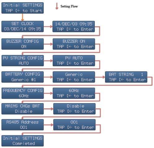
25 8 3 Settings 21
26 You need to set the LVS M Series after first installation so as to have proper operation in the future. After switching on the LVS M Series of the first installation, the initial setting frame comes out automatically. The chart is indicated. Initial setting is a one way flow. You can not come back to previous setting even you set wrong. In case incorrect operation during setting, please set it again later on Set Clock To set clock, press up and down buttons to increase or decrease on blinking characters. Press Enter to change among day, month, year, hour and minute; press Enter to confirm settings. Incorrect clock causes improper operations. Make sure the LVS M Series clock is correct all the time. In case switching off the LVS M Series for more than 5 days, the internal clock setting will lose and change back to the default setting Buzzer Configuration Press Enter button to start setting buzzer on/off. Press Up and Down to change setting. Press Enter again to confirm your selection PV String Configuration This function is to set the string configuration of PV panels for multiple MPPT model. There are 3 options: INDEPENDENT, PARALLEL and AUTO. Independent: 2 input strings are connected to different MPPT of the LVS M Series individually. Parallel: 2 strings are wired together before connecting to the LVS M Series. Auto: If you do not know exactly the configuration, select this. The LVS M Series will judge automatically. This is the default setting. 22
27 8 3 4 Battery Configuration This text shows the battery type and its string number. The available selections are: Generic: it is for general type of lead acid battery. If you are using types other than official ones, please select this type. YUASA NPA100 12I. CHLORIDE12CDC100. PANASONIC LC T12105X. 3K EBB100. After setting the type, you have to set string number, the numbers of battery bank in parallel, as well. The possible selections are 1~4 and >=5. Except Generic, all the other batteries are official ones. Each configuration has its own parameters. Please refer to Battery Charging/Discharging Parameter in Appendix for detail information. If you know parameters of non official; battery, please choose similar battery type of the list to have best performance Frequency Configuration The setting is to set the AC output frequency to 50Hz or 60Hz. You can set frequency once only in initial setting. Please select proper one for your applications. In case AC mains are connected during setting, the LVS M Series will follow AC mains frequency. In this case, frequency configuration frame will not appear during initial setting Mains Charging Battery This setting is to set whether the LVS M Series will use AC mains to charge battery or not. In some applications, you may need AC mains (Grid or Generator) to charge the battery bank when PV power is not enough and battery capacity is low. Select Enable so as to charge battery in this case; select Disable to skip this. Mains maximum current limits the charging current. Charging power equals mains power minus load power. 23

28 8 3 7 Set RS485 Address This is to set RS485 address. The selectable address is from 1 ~ 200. Default address is 1. To know the detail of addressing of RS485, please refer to section of Connecting RS Normal Settings Normal setting is used to set the unit whenever you would like to. Its process is similar to initial setting except operation flow as below: In case you would like to set the LVS M Series, just use Menu Up and Menu Down buttons to Setting Frame and press Confirm button 3 times in 2 seconds to start. 8 5 Factory Setting The LVS M Series can be restored to factory setting. If you like to do this, please ask for your local service. 8 6 Manual ON/OFF The manual ON/OFF switch is beneath the LVS M Series as figure shown below: 24
29 This switch is used to turn ON/OFF the LVS M Series manually. In case battery capacity is enough, push the button to start the LVS M Series. The LVS M Series will supply power from battery bank to your loads. To turn off the LVS M Series, push the switch again, all the AC output will be off and the LVS M Series will shutdown itself. 8 7 DC Switch of PV (optional) This switch is used to turn on or off the PV inputs. The positions are shown as below figures. 25
30 Section 9: LCD Display 9 1 LCD Display Chart * Note: In case no operation for 1 minute, LCD will go back to home frame automatically. Event frame will not appear in case there is no error/event. To enter setting frame, you have to press Enter button three times in 2 seconds. 9 2 Home Frame Home frame shows the operation status and related data at first text line. It shows date and time at second line. 26
31 Mode Display in First Line Description Normal Local Load XXXXW The LVS M Series supplies power of XXXXW from PV and/or battery to load. Display on Power frame 1 will show From Solar XXXXW and From BAT XXXXW. Bypass From Mains XXXXW Load power is from AC mains. Display on Power frame 1 will show From Mains XXXXW. Warning Refer to warning On warning or error happening, the LVS M Series shows message the warning messages. Error Refer to error On error happening, the LVS M Series shows the error message messages. Manual OFF Manual off, push ON/OFF to turn on Manual off. Load will continuously be supplied by Grid. 9 3 Power Frame 1 Showing the instant power from different sources: Display in First Line From Solar XXXXW From Grid XXXXW Description The power coming from PV under normal mode. The power coming from Grid (Mains) under bypass mode. Display in Second Line To BAT XXXXW From BAT XXXXW The power charged to battery. The power comes from battery. Description 9 4 Power Frame 2 Showing the accumulated energy of local consumption and grid: Display LEtoday XXXKWh GEtoday XXXKWh Description Local energy consumption of the day. Grid energy supplied of the day. 9 5 Battery Frame Showing battery status: 27
32 Display BAT Charging BAT Level Medium Description Battery status. Charging, Discharging, Standby or Disconnected. Battery capacity level. Full, High, Medium, and Low. Battery efficiency varies from many factors and is difficult to calculate. The power reading on the LVS M Series display is a calculation for indication of system operation. 9 6 Setting Frame Press Enter button 3 times in 2 seconds on setting frame, the setting procedure starts. Refer to setting in previous section for detail information. 9 7 Error Frame Display in First Line Error 0 Error XX Error number is zero. Total error accounts. Description Display in Second Line No Error Tap Enter button No error recorded. Description Press Enter button to see error detail. Total errors can be recorded are 50. For error large than 50, latest one will replace earliest one. If you like to see the error types, please tap Enter button and using UP and Down buttons to see the detail. The format will be: Line 1 Line 2 Description Error XX Error Message Line 1 shows the error number, line 2 tells you the error message. The messages are listed in tables of error and warning in section Event Frame. 9 8 System Frame The F/W version of the LVS M Series appears in this frame. In case service is required, please tell this information to your service agent. 9 9 Voltage Frame 28
33 This frame display major system voltage of PV1, PV2, Mains, Battery, alternatively Event Frame In the cases there are events such as errors, warnings and reminding, event frame will appear automatically. The prompt information is listed in error and warning tables below. Error Message Line 1 Line 2 Buzzer Description AC VOLT HIGH Vac XXX V Silent ACV is higher than upper limit AC VOLT LOW Vac XXX V Silent ACV is less than lower limit AC FREQ HIGH Fac XX.X Hz Silent AC frequency is more than upper limit AC FREQ LOW Fac XX.X Hz Silent AC frequency is less than lower limit PV VOLT HIGH Vpv XXX V Continue PV is higher than upper limit BAT VOLT HIGH Vbat XX.X V Continue Battery voltage is higher than upper limit OVERLOAD Output is off Continue Output is overload more than defined time, output is cutoff O/P SHORT CKT REMOVE CKT. Continue Output is short NO BATTERY Check BAT Conn. Continue Battery is not connected CX No Display C1 ~ C7 error, reserved for internal diagnose Warning Message Line 1 Line 2 Buzzer Description XX% Load Pay Attention Every 0.5 sec The load is between 85% and 100% 1XX% Load Pls. Reduce Load Every 0.5 sec The load is between 101% and 110% Low Bat. Cap. Will Shutdown Every 0.5 sec Battery low and will shutdown Fan Fails Check or Replace Every 0.5 sec External fan does not work properly 29

34 Section 10: Interface 10 1 RS485 RS485 interface aims to monitor the LVS M Series. You need to have RS485 connection and related software. Please refer to Connecting RS485 for proper connection and setting. Please refer to software manual for installation and application USB Download Data to USB Stick You can plug in a pre formatted USB stick into USB port to download the operation data. The stick must be FAT or FAT32 formatted. To do this, plug in USB stick, LCD will show Download Data Processing. After plugging in the USB, all data inside the LVS M Series will be downloaded to the stick automatically. LCD will show corresponding status. After downloading, while LCD shows Download Data Finished, you can then pull off USB stick. Data download in USB disk are in a file of CSV format. If your USB disk contains firmware for an update, the LVS M Series not download data to USB stick Firmware Upgrade You can upgrade the LVS M Series by USB disk with official firmware. To do this, you need to have firmware in USB stick. To update by USB, please get the latest firmware, save it into a blank USB disk, plug USB disk to the LVS M Series, it will start the upgrade automatically. For detail information, please also consult your local service. To prevent unexpected stop, before starting upgrade, make sure PC or Mains are available. 30
35 The internal memory can store up to 1 month length of data. Data older than this period will be replaced by latest data automatically. Once data in the logger has been deleted, it cannot be recovered. Therefore it is recommended to backup data periodically if you wish to retain this information. 31
36 Section 11: Trouble Shooting Trouble No display or incorrect display Error on display C4 appears Unable to charge batteries RS485 does not work Internal Comm. error Solution 1. Make sure all PV and battery is properly connected. 2. Check battery fuse and switch (breaker) is on. 3. Check AC (Mains). If no AC, try to push Manual On/Off button. 4. If above actions are useless, please DO NOT push manual on/off any more, call your service immediately. 1. C# Error: switch off all AC and DC then switch on the DC and then the AC again. 2. If above error continues, please contact with local service. C4 means internal over temperature. Please: 1. Review installation location, cooler ambient is preferred. 2. Clean up dust on fans and ventilation holes. 3. If C4 continues, please contact with local service. 1. Improper battery type. Please use official batteries. 2. The life cycle of battery ends. Please replace batteries. 3. Improper battery connection. Please check the wirings between the LVS M Series and battery bank. 1. Check all wiring, connection and polarity. 2. Try to switch On or Off terminal DIP switch 1. Green status LED is flashing 2. Please contact with local service. 32
37 Section 12: Maintenance 12 1 Regular Maintenance Keep proper distance from other obstacles. Make sure air flow and heat dissipation path is cleared. Clean up any dust on this unit, especially on the ventilation holes. Check operation and status if possible. Check all wiring and cables Replacing Fans For years of operation, the fans of the LVS M series may be worn out. When the fans are very noisy or stopped, please replace fans. Please follow below steps: To replace the fan, it is required to have qualified and authorized technician. Before replacing fan, please turn both AC and DC off. 1. Switch PV, DC and AC off. 2. Remove screws, open fan cover. 3. Remove screws of fan. 4. Take fan out. 5. Unplug fan connector. 6. Replace new fan supplied by authorized dealer. 7. Close and fix this cover again with screws. 33
38 12 3 Replacing Fuse For some abnormal situations such as overload on AC out, the AC fuse may be broken. If this happens, you need to replace the fuse (35A/250VAC, fast acting). There is a spare fuse in accessory. Take that fuse and follow below figure and replace it. 34
39 Appendix: Battery Charging/Discharging Parameter Type No. Charging Current Charging Voltage Cutoff Voltage Generic >= Yuasa NPA100 12I >= Chloride CDC >= K EBB >= PANASONIC LC T >= * Note: The voltage indicated is for single 12V battery. Cutoff voltage is the voltage of rated power. E.G.: for one string, it is the voltage of 150A discharging. 35
Manual. BlueSolar Grid Inverter 1500 / / / / / 230
 Manual EN BlueSolar Grid Inverter 1500 / 230 2000 / 230 2800 / 230 4000 / 230 5000 / 230 Before you start This manual contains important information regarding installation and safe operation of this unit.
STONESTAR AUSTRALIA PTY LTD
 42 48 REDWOOD DRIVER,DINGLEY VIC3172,AUSTRALIA TEL:0061 3 95518393 FAX:0061 3 95580776 EMAIL:stonestar@ssawheels.com.au Contents 1. Product Introduction... 3 2. Installation... 5 1) Safety instructions...
User Manual. Solar Charge Controller 3KW
 User Manual Solar Charge Controller 3KW 1 CONTENTS 1 ABOUT THIS MANUAL... 3 1.1 Purpose... 3 1.2 Scope... 3 1.3 SAFETY INSTRUCTIONS... 3 2 INTRODUCTION... 4 2.1 Features... 4 2.2 Product Overview... 5
On Line UPS. LUC 1000E / LUC 2000E / LUC 3000E User Manual
 On Line UPS LUC 1000E / LUC 2000E / LUC 3000E User Manual Save This Manual Please read this manual carefully prior to storage, installation, wiring, operation and maintenance of the UPS. This manual contains
User Manual Solar Charge Controller 3KW
 User Manual Solar Charge Controller 3KW Version: 1.3 CONTENTS 1 ABOUT THIS MANUAL... 1 1.1 Purpose... 1 1.2 Scope... 1 1.3 SAFETY INSTRUCTIONS... 1 2 INTRODUCTION... 2 2.1 Features... 2 2.2 Product Overview...
SOLAR INVERTER/CHARGER 1000VA/1500VA/2000VA. Appliances. PC TV Light Electricfan
 SOLAR INVERTER/CHARGER SOLAR INVERTER/CHARGER 1000VA/1500VA/2000VA Appliances 420-00300-02 PC TV Light Electricfan Table Of Contents GENERAL PRECAUTIONS... 1 PERSONNEL PRECAUTIONS... 1 INTRODUCTION...
RESISTIVE LOAD XP300C
 RESISTIVE LOAD XP300C Via della Torricella, 22 50012 ANTELLA (FI) - Italy Tel. +39 055 620508 Fax +39 055 620338 e-mail: marelita@tin.it www.marelweb.it INDEX GENERAL...3 OPERATION AND USE...3 WARNINGS...3
Solar Charge Controller
 Table 3: Charging voltage for 4 types of battery Battery Type Battery Type Code SC-600W MPPT Bulk Voltage Floating Voltage Vented 01 28.6 V 26.4 V Sealed 02 28.6 V 26.8 V Gel 03 28.6 V 27.4 V NiCd 04 28.6
SCC-MPPT Solar Charge Controller
 Table 3: Charging voltage for 4 types of battery Battery Battery 12V battery system 24V battery system Type Type Code Bulk Floating Bulk Floating Vented 01 14.3 V 13.2 V 28.6 V 26.4 V Sealed 02 14.3 V
User Manual 1KVA-5KVA INVERTER / CHARGER
 User Manual 1KVA-5KVA INVERTER / CHARGER Version: 1.7 Table Of Contents ABOUT THIS MANUAL... 1 Purpose... 1 Scope... 1 SAFETY INSTRUCTIONS... 1 INTRODUCTION... 2 Features... 2 Basic System Architecture...
HYBRID 5048E. Hybrid Inverter INSTALLATION AND OPERATION MANUAL. Version 2.0E
 HYBRID 5048E Hybrid Inverter INSTALLATION AND OPERATION MANUAL Version 2.0E SAFETY INSTRUCTIONS Risk of Electric Shock Alternating Current (AC) and Direct Current (DC) sources are connected to this device.
User manual. Solar Hybrid 1-5KVA. Uninterruptible Power Supply / Charger
 User manual Solar Hybrid 1-5KVA Uninterruptible Power Supply / Charger All rights reserved. The information in this document is subject to change without notice. Thank you for purchasing this series UPS.
User Manual 1.5KVA-3KVA INVERTER / CHARGER. Version: 1.1
 User Manual 1.5KVA-3KVA INVERTER / CHARGER Version: 1.1 Table Of Contents ABOUT THIS MANUAL... 1 Purpose... 1 Scope... 1 SAFETY INSTRUCTIONS... 1 INTRODUCTION... 2 Features... 2 Basic System Architecture...
Sine Wave Solar UPS. Owner s Manual. Thank you for choosing the intelligent NON STOP Solar UPS with state of art technology.
 Sine Wave Solar UPS Owner s Manual KSU 1024S, KSU 2048S Thank you for choosing the intelligent NON STOP Solar UPS with state of art technology. Please read this guide carefully before installing the product.
User Manual. Hybrid PV Inverter. Version: 2.1
 User Manual Hybrid PV Inverter Version: 2.1 Table Of Contents 1. Introduction...1 2. Important Safety Warning...2 3. Unpacking & Overview...4 3-1. Packing List... 4 3-2. Product Overview... 4 4. Installation...5
Maximum Power Point Tracking (MPPT) KA1224MPPT20A KA1224MPPT40A. Solar Charge Controller. User Manual 20A
 KA1224MPPT20A KA1224MPPT40A. Solar Charge Controller. User Manual 20A") Maximum Power Point Tracking (MPPT) KA1224MPPT20A - KA1224MPPT40A Solar Charge Controller User Manual Model Battery voltage Max. solar panel voltage Charging current KA1224MPPT20A KA1224MPPT40A 12V/24V
Maximum Power Point Tracking (MPPT) KA1224MPPT20A - KA1224MPPT40A Solar Charge Controller User Manual Model Battery voltage Max. solar panel voltage Charging current KA1224MPPT20A KA1224MPPT40A 12V/24V
Solar Hybrid Power Generating System CPS1200EOH12SC CPS2200EOH24SC CPS3000EOH24SC. User s Manual K01-C
 Solar Hybrid Power Generating System CPS1200EOH12SC CPS2200EOH24SC CPS3000EOH24SC User s Manual K01-C000304-02 2 TABLE OF CONTENTS 1 IMPORTANT SAFETY INSTRUCTIONS..4 2 INSTALLATION....5 2-1 Unpacking...5
User Manual. 3kW Hybrid PV Inverter HX-3000
 User Manual 3kW Hybrid PV Inverter HX-3000 Table Of Contents 1. Introduction...1 2. Important Safety Warning...2 3. Unpacking & Overview...4 3-1. Packing List... 4 3-2. Product Overview... 4 4. Installation...5
SCC-MPPT Solar Charge Controller
 Table 4: Alarm point for low battery voltage table Model Alarm point SCC-MPPT-300 10.5 V SCC-MPPT-600 21.0 V Table 5: Charging hour table for reference Battery Capacity To 90% capacity @ 25A charging current
SCC-MPPT Solar Charge Controller
 Solar Charge Controller Quick Guide 200W 300W 400W 600W 850W V. 2.2 1. Introduction solar charge controller uses PWM-based DSP controller to keep the batteries regulated and prevent batteries from overcharging
User Manual 1.5KVA-3KVA INVERTER / CHARGER
 User Manual 1.5KVA-3KVA INVERTER / CHARGER Version: 1.0 Table Of Contents ABOUT THIS MANUAL... 1 Purpose... 1 Scope... 1 SAFETY INSTRUCTIONS... 1 INTRODUCTION... 2 Features... 2 Basic System Architecture...
User Manual 4KVA/ 5KVA INVERTER / CHARGER. With MPPT Controller
 User Manual 4KVA/ 5KVA INVERTER / CHARGER With MPPT Controller CONTENTS ABOUT THIS MANUAL... 1 Purpose... 1 Scope... 1 SAFETY INSTRUCTIONS... 1 INTRODUCTION... 2 Features... 2 Basic System Architecture...
User Manual LV 3KVA-24V INVERTER / CHARGER. Version: 1.1
 User Manual LV 3KVA-24V INVERTER / CHARGER Version: 1.1 Table of Contents ABOUT THIS MANUAL... 1 Purpose... 1 Scope... 1 SAFETY INSTRUCTIONS... 1 INTRODUCTION... 2 Features... 2 Basic System Architecture...
SOLAR INVERTER/CHARGER SOLAR INVERTER/CHARGER MPPT 2KVA- 3KVA. Appliances. Airconditioning Fridge. Washing machine
 SOLAR INVERTER/CHARGER SOLAR INVERTER/CHARGER MPPT 2KVA- 3KVA Appliances 420-00288-01 PC TV Airconditioning Fridge Washing machine Table Of Contents ABOUT THIS MANUAL...1 Purpose... 1 Scope... 1 SAFETY
User Manual / Manuel utilisateur
 User Manual / Manuel utilisateur Inverter Charger / Convertisseur Chargeur English version...1 English Version 1 Table of Contents ABOUT THIS MANUAL... 3 Purpose... 3 Scope... 3 SAFETY INSTRUCTIONS...
1KVA/ 2KVA/ 3KVA/ 4KVA/ 5KVA MS, LV MPPT INVERTER / CHARGER. User Manual. Version: 2.3
 1KVA/ 2KVA/ 3KVA/ 4KVA/ 5KVA MS, LV MPPT INVERTER / CHARGER User Manual Version: 2.3 Table Of Contents ABOUT THIS MANUAL... 1 Purpose... 1 Scope... 1 SAFETY INSTRUCTIONS... 1 INTRODUCTION... 2 Features...
UGE-4K Off-Grid Controller OWNER S MANUAL
 UGE-4K Off-Grid Controller OWNER S MANUAL CONTENTS INTRODUCTION... 3 PARTS LIST... 4 SPECIFICATIONS... 5 SAFETY INSTRUCTIONS... 6-7 INSTALLATION... 8 MOUNTING GUIDE... 9 WIRING DIAGRAM... 10 CONTROLLER
User Manual 5KVA/5KW INVERTER / CHARGER. Version: 1.3
 User Manual 5KVA/5KW INVERTER / CHARGER Version: 1.3 Table Of Contents ABOUT THIS MANUAL... 1 Purpose... 1 Scope... 1 SAFETY INSTRUCTIONS... 1 INTRODUCTION... 2 Features... 2 Basic System Architecture...
USER MANUAL. Blazer Vista 1000/1400/2000. Uninterruptible Power System
 USER MANUAL Blazer Vista 1000/1400/2000 Uninterruptible Power System IMPORTANT SAFETY INSTRUCTIONS SAVE THESE INSTRUCTIONS This manual contains important instructions for model Blazer Vista 1000/1400/2000
8 Troubleshooting and Maintenance
 8 Troubleshooting and Maintenance 8.1 Troubleshooting 8.1.1 Troubleshooting of LED Indicators See Tab. 7-4 State Descriptions of LED Indicators for the definition. Fault Type LED indicators and LCD screen
MPPT Controller PVTS Series User Manual. User Manual. 800W-4000W Hybrid solar inverter. Version: 1.4
 User Manual 800W-4000W Hybrid solar inverter Version: 1.4 Table Of Contents ABOUT THIS MANUAL... 1 Purpose... 1 Scope... 1 SAFETY INSTRUCTIONS... 1 INTRODUCTION... 2 Features... 2 Basic System Architecture...
Solar Hybrid Inverter SP Brilliant Grid Series
 User Manual Solar Hybrid Inverter SP Brilliant Grid Series Version: 1.3 Table Of Contents ABOUT THIS MANUAL... 1 Purpose... 1 Scope... 1 SAFETY INSTRUCTIONS... 1 INTRODUCTION... 2 Product Overview... 3
Solar Hybrid Inverter SP Efecto Series
 User Manual Solar Hybrid Inverter SP Efecto Series Version 1.2 Table Of Contents ABOUT THIS MANUAL... 1 Purpose... 1 Scope... 1 SAFETY INSTRUCTIONS... 1 INTRODUCTION... 2 Features... 2 Basic System Architecture...
User Manual 1KVA/ 2KVA/ 3KVA INVERTER / CHARGER
 User Manual 1KVA/ 2KVA/ 3KVA INVERTER / CHARGER CONTENTS ABOUT THIS MANUAL... 1 Purpose... 1 Scope... 1 SAFETY INSTRUCTIONS... 1 INTRODUCTION... 2 Features... 2 Basic System Architecture... 2 Product Overview...
POWER TROLLEY 8 INSTRUCTION MANUAL POWER TROLLEY 8. Model: SINE Instruction Manual for: Self-Contained Sinewave Mobile Power Backup System
 POWER TROLLEY 8 Model: SINE 1548 Instruction Manual for: Self-Contained Sinewave Mobile Power Backup System Version 07 CONTENTS Page 1. INTRODUCTION... 1 2. USING THE POWER TROLLEY.... 2 3. BATTERY BACKUP
Solar Hybrid Inverter SP Brilliant Series
 User Manual Solar Hybrid Inverter SP Brilliant Series Version: 1.5 Table Of Contents ABOUT THIS MANUAL... 1 Purpose... 1 Scope... 1 SAFETY INSTRUCTIONS... 1 INTRODUCTION... 2 Features... 2 Basic System
CX-SERIES ADVANCED BATTERY CHARGER
 CX-SERIES ADVANCED BATTERY CHARGER Table of Content 1. IMPORTANT SAFETY INFORMATION... 2 1-1 General Safety Precautions... 2 1-2 Battery Precautions... 2 2. FEATURES... 3 2-1 Battery Charging Curve...
MPPT Solar Integrated Inverters (500VA~2500VA) User Manual THE SOLAR TECH CO.,LTD. Solar Integrated Inverter Series 500VA~2500VA 13.
 User Manual THE SOLAR TECH CO.,LTD. Solar Integrated Inverter Series 500VA~2500VA 13.") MPPT Solar Integrated Inverters (500VA~2500VA) User Manual THE SOLAR TECH CO.,LTD. - 1 - Table of Contents 1. SALIENT FEATURES...3 2.. PRODUCT INSTALLATION & PRECAUTIONS...3 2.1. PRODUCT INSTALLATION &
MPPT Solar Integrated Inverters (500VA~2500VA) User Manual THE SOLAR TECH CO.,LTD. - 1 - Table of Contents 1. SALIENT FEATURES...3 2.. PRODUCT INSTALLATION & PRECAUTIONS...3 2.1. PRODUCT INSTALLATION &
Power Inverter. User s Manual. Diamond Series CPD1200EILCD
 Power Inverter Diamond Series CPD1200EILCD User s Manual 2 TABLE OF CONTENTS 1 IMPORTANT SAFETY INSTRUCTIONS..4 2 INSTALLATION....5 2-1 Unpacking...5 2-2 Product Overview & Outlook..5 2-3 Power Requirements
1. Important Safety Warning
 Table of Contents 1. Important Safety Warning... 1 1-1. Transportation... 1 1-2. Preparation... 1 1-3. Installation... 1 1-4. Operation... 1 1-5. Maintenance, service and faults... 2 2. Installation and
User Manual 1KVA-5KVA INVERTER / CHARGER. Version: 2.1
 User Manual 1KVA-5KVA INVERTER / CHARGER Version: 2.1 Table Of Contents ABOUT THIS MANUAL... 1 Purpose... 1 Scope... 1 SAFETY INSTRUCTIONS... 1 INTRODUCTION... 2 Features... 2 Basic System Architecture...
User Manual Digital Energy Uninterruptible Power Supply ML Series UPS VA GE Digital Energy Power Quality
 GE Digital Energy Power Quality User Manual Digital Energy Uninterruptible Power Supply ML Series UPS 350-500-700-1000 VA GE imagination at work GB User Manual Digital Energy Uninterruptible Power Supply
CP-250E-60/72-208/240-MC4 Microinverter with Modular Trunk Cable
 CP-250E-60/72-208/240-MC4 Microinverter with Modular Trunk Cable Chilicon Power Aug 2016 1 CONTENTS CP-250E Microinverter System... 3 The CP-100 Cortex Gateway... 3 Important Safety Information... 4 Inverter
Users Manual. Defender 1 8.0KW to 14.0KW Online Emergency Lighting Inverter. Technical Manual # Revision B
 Users Manual Defender 1 8.0KW to 14.0KW Online Lighting Inverter Technical Manual #018-0102-01 Revision B Phone: 1.877.DSPM.POWER 1.877.377.6769 Fax: 909.930.3335 Website: www.dspmanufacturing.com E-Mail:
Users Manual. Cobra Plus Stand-By Emergency Lighting Inverter. Technical Manual # Revision B
 Users Manual Cobra Plus Stand-By Lighting Inverter Technical Manual #018-0110-01 Revision B Phone: 1.877.DSPM.POWER 1.877.377.6769 Fax: 909.930.3335 Website: www.dspmanufacturing.com E-Mail: techsupport@dspmanufacturing.com
:43 1/13 Victron & BYD B-Box
 2018-11-04 15:43 1/13 Victron & BYD B-Box Victron & BYD B-Box The combination of Victron products with BYD B-Box lithium batteries (2.5, 5.0, 7.5, 10.0 and 12.8 models) has been tested and certified by
UPS Wizard User s Manual
 1. The communication cable M2502: This is a special designed cable for the communication of UPS with your PC; only connecting with the correct cable, the PC can detect the UPS. 2. The main window of the
User Manual. Digital Energy Uninterruptible Power Supply ML Series UPS VA. GE Digital Energy Power Quality. GE imagination at work
 GE Digital Energy Power Quality User Manual Digital Energy Uninterruptible Power Supply ML Series UPS 350-500-700-1000 VA GE Consumer & Industrial SA General Electric Company CH 6595 Riazzino (Locarno)
User Manual 1KVA-5KVA (PF1) INVERTER / CHARGER. Version: 1.0
 INVERTER / CHARGER. Version: 1.0") User Manual 1KVA-5KVA (PF1) INVERTER / CHARGER Version: 1.0 Table Of Contents ABOUT THIS MANUAL... 1 Purpose... 1 Scope... 1 SAFETY INSTRUCTIONS... 1 INTRODUCTION... 2 Features... 2 Basic System Architecture...
User Manual 1KVA-5KVA (PF1) INVERTER / CHARGER Version: 1.0 Table Of Contents ABOUT THIS MANUAL... 1 Purpose... 1 Scope... 1 SAFETY INSTRUCTIONS... 1 INTRODUCTION... 2 Features... 2 Basic System Architecture...
BRAVER UPS. (Uninterruptible Power System) User s Manual
 User s Manual") BRAVER UPS (Uninterruptible Power System) User s Manual Safety CAUTION! This UPS utilizes voltages that may be hazardous. Do not attempt to disassemble the unit. The unit contains no user replaceable parts.
BRAVER UPS (Uninterruptible Power System) User s Manual Safety CAUTION! This UPS utilizes voltages that may be hazardous. Do not attempt to disassemble the unit. The unit contains no user replaceable parts.
4KVA/5KVA Parallel Installation Guide
 1. Introduction 4KVA/5KVA Parallel Installation Guide This inverter can be used in parallel with two different operation modes. 1. Parallel operation in single phase with up to 6 units. The supported maximum
Multifunction Electronic Load (EBC-A10) User Manual EBC-A10 User Manual Copyright (C) ZKE Technology
 User Manual EBC-A10 User Manual Copyright (C) ZKE Technology") Multifunction Electronic Load (EBC-A10) User Manual 1. Features 1.1 Battery capacity test The tester is designed for charging lead-acid/lithium battery (pack), and discharge/capacity test of all kinds
Multifunction Electronic Load (EBC-A10) User Manual 1. Features 1.1 Battery capacity test The tester is designed for charging lead-acid/lithium battery (pack), and discharge/capacity test of all kinds
Accessories for Stand-alone inverter SUNNY ISLAND GENMAN
 Accessories for Stand-alone inverter SUNNY ISLAND GENMAN Technical Description GenMan-TEN082730 98-2001230 Version 3.0 EN SMA Solar Technology AG Table of Contents Table of Contents 1 Notes on this manual..............................
KIT-STCS60D KIT-STCS100D Solar Suitcase 60W and 100W Owner s Manual
 KIT-STCS60D KIT-STCS100D Solar Suitcase 60W and 100W Owner s Manual RNG Group Inc. (Renogy) 14288 Central Ave., Suite A Chino, CA 91710 1-800-330-8678 Product Description The Renogy Solar Suitcases combine
3KW Off-grid Solar Power System LFP Battery
 3KW Off-grid Solar Power System LFP Battery 1 CATALOGUE 1. S u m m a r y 3 2. T e c h n i c a l p a r a m e t e r 4 3. D i s p l a y a n d f u n c t i o n i n s t r u c t i o n 5 4. S e q u e n c e o f
SOLARINVERTER MPPT 4KVA - 5KVA
 SOLARINVERTER SOLARINVERTER MPPT 4KVA - 5KVA 420-00286-01 Table of Contents ABOUT THIS MANUAL...1 Purpose...1 Scope...1 SAFETY INSTRUCTIONS...1 INTRODUCTION...2 Features...2 Basic System Architecture...2
User Manual. Axpert King 3.2KW/5.2KW 48V MPPT SOLAR INVERTER. Version: 1.0
 User Manual Axpert King 3.2KW/5.2KW 48V MPPT SOLAR INVERTER Version: 1.0 Table Of Contents ABOUT THIS MANUAL... 1 Purpose... 1 Scope... 1 SAFETY INSTRUCTIONS... 1 INTRODUCTION... 2 Features... 2 Basic
User Manual 1KVA-5KVA INVERTER / CHARGER
 User Manual 1KVA-5KVA INVERTER / CHARGER Table Of Contents ABOUT THIS MANUAL... 1 Purpose... 1 Scope... 1 SAFETY INSTRUCTIONS... 1 INTRODUCTION... 2 Features... 2 Basic System Architecture... 2 Product
Villager III. User Instructions. GTIS Power Systems
 Villager III User Instructions GTIS Power Systems power_systems@sil.org Introduction Figure 1: View showing Villager III and dc dc adapter The Villager III Power Bank may be used to power devices that
Solar Hybrid Inverter SP Efecto Series
 User Manual Solar Hybrid Inverter SP Efecto Series Version 1 Table Of Contents ABOUT THIS MANUAL... 1 Purpose... 1 Scope... 1 SAFETY INSTRUCTIONS... 1 INTRODUCTION... 2 Features... 2 Basic System Architecture...
c-go 12V/10A 12V/20A Power supply and battery charger Instruction manual
 c-go 12V/10A 12V/20A Power supply and battery charger GB Instruction manual 1 Index 1. Product description... 2 2. Safety advices... 3 3. Mounting and installation... 4 4. Operation... 5 5. Problem solving...
FlinSlim Lite Solar Hybrid Inverter 1KVA-5KVA USER MANUAL. Version: 1.3
 1KVA-5KVA USER MANUAL Version: 1.3 Table Of Contents ABOUT THIS MANUAL... 1 Purpose... 1 Scope... 1 SAFETY INSTRUCTIONS... 1 INTRODUCTION... 2 Features... 2 Basic System Architecture... 2 Product Overview...
User Manual. SP10000 Premium
 User Manual Solar Hybrid 3Phase PV Inverter SP10000 Premium Version: 1.2 Table Of Contents 1. Introduction... 1 2. Important Safety Warning... 2 3. Unpacking & Overview... 4 3-1. Packing List... 4 3-2.
User Manual 3KVA-5KVA INVERTER / CHARGER. Version: 1.1
 User Manual 3KVA-5KVA INVERTER / CHARGER Version: 1.1 Table Of Contents ABOUT THIS MANUAL... 1 Purpose... 1 Scope... 1 SAFETY INSTRUCTIONS... 1 INTRODUCTION... 2 Features... 2 Basic System Architecture...
3 40W. Product Introduction. 1440mm(56.7in) 560mm (22in) 440mm (17.3in
 560mm (22in) 440mm (17.3in") Product Introduction 1440mm(56.7in) 560mm(22in) 1 3 9 7 2 6 8 560mm (22in) 4 440mm (17.3in 5 Items 1 3x40 Watts Solar Panel 2 10A Charge Controller 3 Alligator clips 4 Suitcase with handle and pocket 5
Product Introduction 1440mm(56.7in) 560mm(22in) 1 3 9 7 2 6 8 560mm (22in) 4 440mm (17.3in 5 Items 1 3x40 Watts Solar Panel 2 10A Charge Controller 3 Alligator clips 4 Suitcase with handle and pocket 5
Duo Battery Charge Controller
 Duo Battery Charge Controller RENOGY 10A 20A Pulse Width Modulation Solar Charge Controller Manual 1 2775 E. Philadelphia St., Ontario CA 91761 1-800-330-8678 Version: 1.2 Important Safety Instructions
MPPT SOLAR CONTROLLER FOR MODELS: 20A baterai 12V 24V
 Main Features MPPT SOLAR CONTROLLER FOR MODELS: 20A baterai 12V 24V 20A MPPT solar charge controller MPPT technology Built-in DSP controller with high performance Automatic battery voltage detection for
APPENDIX: APPROCIMATR BACK-UP TIME TABLE
 9KW-12KW 1 Power Inverter Limitada, dirección Pasaje Enrique Campino 763, La Florida, Santiago CHILE, Tel. 227615261 www.powerinverter.cl email: ventas@powerinverter.cl ABOUT THIS MANUAL 1 SAFETY INSTRUCTIONS
Solar inverter with MPPT AX II - M series: 4 / 5 kva, AX II - P series: 3 kva. With integrated star point grounding* according to VDE AR-E 2510-
 Solar inverter with MPPT AX II - M series: 4 / 5 kva, AX II - P series: 3 kva With integrated star point grounding* according to VDE AR-E 2510- and power factor 1.0 AX-M series: Part numbers: 4000 VA 5000
DC TO AC POWER INVERTER PWRIC150012W INSTRUCTION MANUAL
 DC TO AC POWER INVERTER PWRIC150012W INSTRUCTION MANUAL SAVE THIS MANUAL You will need the manual for the safety warnings and precautions, assembly instructions, operating and maintenance procedures, parts
CONTENTS 1. INTRODUCTION SAFTY INSTRUCTION CABLE CONNECTION SYSTEM DESCRIPTION INVERTER OPERATION...
 CONTENTS 1. INTRODUCTION...... 1 2. SAFTY INSTRUCTION.......... 2 3. CABLE CONNECTION.......... 4 4. SYSTEM DESCRIPTION............ 5 5. INVERTER OPERATION... 11 6. TROUBLE SHOOTING GUIDE....... 16 7.
USER MANUAL. PowerMust 1400/2000 LCD. Uninterruptible Power System
 USER MANUAL PowerMust 1400/2000 LCD Uninterruptible Power System IMPORTANT SAFETY INSTRUCTIONS SAVE THESE INSTRUCTIONS This manual contains important instructions for model Power Must 1400/2000 LCD that
c-go 24V/6A 24V/8A 24V/12A
 c-go 24V/6A 24V/8A 24V/12A Battery charger GB Instruction manual 1 Index 1. Product description... 2 2. Safety advices... 3 3. Quick start guide... 4 4. Operation... 4 5. Problem solving... 6 6. Specifications...
USER MANUAL. E4 LCD TX 5000(S) / 6000(S) / (S) With Output Isolation Transformer. Uninterruptible Power Supply System
 / 6000(S) / (S) With Output Isolation Transformer. Uninterruptible Power Supply System") USER MANUAL E4 LCD TX 5000(S) / 6000(S) / 10 000(S) With Output Isolation Transformer Uninterruptible Power Supply System Table of Contents 1. IMPORTANT SAFETY INSTRUCTIONS:... 2 1-1. TRANSPORTATION...
USER MANUAL E4 LCD TX 5000(S) / 6000(S) / 10 000(S) With Output Isolation Transformer Uninterruptible Power Supply System Table of Contents 1. IMPORTANT SAFETY INSTRUCTIONS:... 2 1-1. TRANSPORTATION...
User Manual SOLARMAX 1KVA/ 2KVA/ 3KVA INVERTER / CHARGER
 User Manual SOLARMAX 1KVA/ 2KVA/ 3KVA INVERTER / CHARGER WWW.POWERHIGHWAY.NET CONTENTS ABOUT THIS MANUAL... 1 Purpose... 1 Scope... 1 SAFETY INSTRUCTIONS...... 1 INTRODUCTION... 2 Features... 2 Basic System
User Manual. Hybrid 4KW PV Inverter. Version: 1.2
 User Manual Hybrid 4KW PV Inverter Version: 1.2 Table of Contents 1. Introduction... 1 2. Important Safety Warning... 2 3. Unpacking & Overview... 4 4. Installation... 5 4. Grid (Utility) Connection...
Super Brain 989 The Pinnacle of Performance with Power to Spare User s Manual Model Rectifier Corporation
 Super Brain 989 The Pinnacle of Performance with Power to Spare User s Manual Temperature sensor jack Sensor included Model Rectifier Corporation Please read this entire manual including all Safety Cautions,
DC TO AC POWER INVERTER
 DC TO AC POWER INVERTER 12V / 24V / 48Vdc Input 115V / 230Vac Output 150W ~ 6000W Output cont. L-Series User Manual Before install and use your Inverter, read the User Manual and safety instructions. Cooler
Subject Underhood G System Error Codes and Symptoms System or Parts affected
 System or Parts affected Index Underhood70G (V90Gxxx) System or Parts affected... 1 Overview... 1 Identifying your System... 1 Retrieving Logged Error Messages... 1 Error Messages... 3 Error Message Table...
Solar Hybrid Inverter SP Initial Series
 User Manual Solar Hybrid Inverter SP Initial Series Version: 1.3 Table Of Contents ABOUT THIS MANUAL... 1 Purpose... 1 Scope... 1 SAFETY INSTRUCTIONS... 1 INTRODUCTION... 2 Features... 2 Basic System Architecture...
PANcharge1k Battery Charger User's Manual
 PANcharge1k Battery Charger User's Manual Ver.1.00E Table of Contents 1. Important Safety Instructions... 3 1-1 General Safety Precautions... 3 1-2 Battery Precautions... 3 1-3 Electromagnetic Disturbance...
USER S MANUAL CONTENTS. Uninterruptible Power Supply 1. INTRODUCTION SAFTY INSTRUCTION CABLE CONNECTION... 4
 USER S MANUAL ON-LINE 1K/2K/3KVA CONTENTS 1. INTRODUCTION...... 1 2. SAFTY INSTRUCTION.......... 2 3. CABLE CONNECTION.......... 4 4. SYSTEM DESCRIPTION............ 5 5. UPS OPERATION...... 12 6. TROUBLE
User Manual 3KW/5KW INVERTER / CHARGER. Version: 1.0
 User Manual 3KW/5KW INVERTER / CHARGER Version: 1.0 Table Of Contents ABOUT THIS MANUAL... 1 Purpose... 1 Scope... 1 SAFETY INSTRUCTIONS... 1 INTRODUCTION... 2 Features... 2 Basic System Architecture...
OPERATIONAL MANUAL EMBC-8025 INTELLIGENT BATTERY CHARGER. Version 1.5
 OPERATIONAL MANUAL EMBC-8025 INTELLIGENT BATTERY CHARGER Version 1.5 1 Product Overview EMBC-8025 is an intelligent switching mode battery charger with float maintenance. It is designed to offer maximum
User Manual G1 Solar MPPT Inverter Solar MPPT Charger English version..1
 User Manual G1 Solar MPPT Inverter Solar MPPT Charger English version..1 English version 1 Table of Contents ABOUT THIS MANUAL... 3 Purpose... 3 Scope... 3 SAFETY INSTRUCTIONS... 3 INTRODUCTION... 4 Features...
& Operation Manual. Growatt 10000HY. Installation GR-UM-A03-A-00
 Growatt 10000HY Installation & Operation Manual GROWATT NEW ENERGY TECHNOLOGY Co.,LTD No.28 Guangming Road, Shiyan, Baoan District, Shenzhen, P.R. China T F E W + 86 755 2747 1900 + 86 755 2747 2131 info@ginverter.com
User Manual. 3/1 10K~30K Online UPS
 User Manual 3/1 10K~30K Online UPS Uninterruptible Power Supply System Version: 1.7 Please comply with all warnings and operating instructions in this manual strictly. Save this manual properly and read
USER S MANUAL SOLAR POWER INVERTER KW-6KW
 USER S MANUAL ------SOLAR POWER INVERTER------ 1KW-6KW Appliances--------------------------------------------- Content Content Content... 1 1 Figures of unit... 2 2 Specification... 3 3 Front panel...
PFC W HF/PFC Battery Charger
 PFC 5000 5000W HF/PFC Battery Charger Description Advanced high frequency switching design with 92% typical efficiency Fully sealed enclosure providing improved reliability in demanding environments >
USER MANUAL. IPS home inverters with UPS function. IPS home inverter manual
 USER MANUAL IPS home inverters with UPS function Suitable for UPS: - IPS300-SIN - IPS300-SIN-WM - IPS300-SIN-DC - IPS600-SIN - IPS600-SIN-WM - IPS600-SIN-DC - IPS1000-SIN - IPS1000-SIN-DC - IPS1600-SIN
HPP1 MK5 Owner s Manual
 J Wolmarans Page 1 2016/09/15 Page 1 of 9 TABLE OF CONTENTS Page 1 Introduction...2 2 Models...2 3 Safety warnings...3 4 Contents...3 5 Installation...3 5.1 Mounting the unit:...3 5.2 Connecting the battery:...3
User Manual 1KW-5KW SOLAR INVERTER / CHARGER. Version: 1.2
 User Manual 1KW-5KW SOLAR INVERTER / CHARGER Version: 1.2 Table Of Contents ABOUT THIS MANUAL... 1 Purpose... 1 Scope... 1 SAFETY INSTRUCTIONS... 1 INTRODUCTION... 2 Features... 2 Basic System Architecture...
StorEdge TM Solution Applications with the StorEdge Interface and LG Chem Batteries Connection and Configuration (Europe, APAC, South Africa)
") StorEdge TM Solution Applications with the StorEdge Interface and LG Chem Batteries Connection and Configuration (Europe, APAC, South Africa) Revision History Version 2.1 (December 2018) Added the requirement
StorEdge TM Solution Applications with the StorEdge Interface and LG Chem Batteries Connection and Configuration (Europe, APAC, South Africa) Revision History Version 2.1 (December 2018) Added the requirement
The function of this Dynamic Active Probe has divided into three preferences on the screen main Menus:
 1.0 Introduction: This probe is designed to provide an additional help to automotive technicians in trouble shooting of electrical circuits problems in the car. Apart from using the normal multi tester,
βeta 20A AUTO 12V/24V SOLAR CHARGE CONTROLLER WITH REMOTE METER
 βeta 20A AUTO 12V/24V SOLAR CHARGE CONTROLLER WITH REMOTE METER USER MANUAL βeta 20A AUTO 12V/24V SOLAR CHARGE CONTROLLER WITH REMOTE METER (OPTIONAL) CHARACTERISTICS LCD display: all systems parameters
Pure Sine Wave Inverter GP-HS1500. Owner s Manual
 Pure Sine Wave Inverter GP-HS1500 Owner s Manual 2 Table of Contents Introduction 3 Specifications 4 Name and Main Function 5 Installation 7 Operation 9 Operating Limits 13 Troubleshooting 13 Maintenance
SBC V In-Car Charger Dual Input (Solar MPPT & DC)
") SBC-5926 12V In-Car Charger Dual Input (Solar MPPT & DC) Operation manual Keep this manual in a safe place for quick reference at all times. This manual contains important safety and operation instructions
SBC-5926 12V In-Car Charger Dual Input (Solar MPPT & DC) Operation manual Keep this manual in a safe place for quick reference at all times. This manual contains important safety and operation instructions
CONTENTS 1. INTRODUCTION SAFTY INSTRUCTION CABLE CONNECTION SYSTEM DESCRIPTION OPERATION... 9
 USER MANUAL 1 CONTENTS 1. INTRODUCTION... 1 2. SAFTY INSTRUCTION... 3 3. CABLE CONNECTION... 4 4. SYSTEM DESCRIPTION... 5 5. OPERATION... 9 6. TROUBLE SHOOTING GUIDE... 25 7. OPERATION MODES..... 27 8.
PV Master OPERATION MANUAL
 PV Master OPERATION MANUAL GoodWe Technical Services Center December, 2017 Ver. 1.00 BRIEF INTRODUCTION PV Master is an external application for GoodWe inverters to monitor or configure inverters or to
USER S MANUAL CONTENTS. Uninterruptible Power Supply 1. INTRODUCTION SAFTY INSTRUCTION SYSTEM DESCRIPTION... 4
 USER S MANUAL PowerWalker VFI 1000 / 3000VA CONTENTS 1. INTRODUCTION...... 1 2. SAFTY INSTRUCTION......... 2 3. SYSTEM DESCRIPTION......... 4 4. CABLE CONNECTION......... 7 5. OPERATION...... 8 6. TROUBLE