SMT. Installation and Operation Manual. Model:SMT WITH MPPT TECHNOLOGY
|
|
|
- Leo Paul
- 5 years ago
- Views:
Transcription

1 SMT WITH MPPT TECHNOLOGY Installation and Operation Manual Model:SMT
2 SMT Dimensions Specification Summary System Voltage 12 V/24V Rated Battery Current 12V, 5A 8A 10A 15A 20A 25A 24V, 5A 8A 10A 15A Rated Load Current 12V(5A--25A) 24V(5A--15A) Max. Input Voltage** Nominal Input Power 75VDC 300W see Section 6.0 for full technical specifications ** Array voltage should never exceed maximum input voltage. Refer to the solar module documentation to determine the highest expected array V oc as defined by the lowest expected ambient temperature for the system location.
3 1.0 Important Safety Information 2.0 General Information 2.1 Overview 2.2 Features 3.0 Installation Instructions 3.1 General Installation Notes 3.2 Mounting 3.3 Wiring 4.0 Operation 4.1 LED Indications 4.2 MPPT Technology 4.3 Battery Charging Information 4.4 Load Control Information 4.5 Protections 4.6 Inspection and Maintenance 5.0 Troubleshooting 5.1 Error Indications 5.2 Common Problems 6.0 Technical Specifications Appendix A - Wire Charts
4 Please keep this manual for future in check. This manual contains important safety, installation and operating instructions for SMT solar controller. The following symbols are used throughout this manual to indicate potentially dangerous conditions or mark important safety instructions. WARNING: Indicates a potentially dangerous condition. Use extreme caution when performing this task. CAUTION: Indicates a critical procedure for safe and proper operation of the controller. NOTE: Indicates a procedure or function that is important for the safe and proper operation of the controller. General Safety Information Read all of the instructions and cautions in the manual before beginning installation. There are no user serviceable parts inside the SMT. Do not disassemble or attempt to repair the controller. Disconnect all sources of power to the controller before installing or adjusting the SMT. There are no fuses or disconnects inside the SMT. Install external fuses/breakers as required. Do not allow water to enter the controller. Confirm that power connections are tightened to avoid excessive heating from a loose connection.
 and also provides load control to prevent over-discharge of the battery.")
5 2.1 Overview Thank you for selecting the SMT charge controller. The controller (SMT) is an advanced maximum power point tracking solar battery charger and load controller for stand-alone PV systems. The controller features a smart tracking algorithm that maximizes the energy from the solar module(s) and also provides load control to prevent over-discharge of the battery. The SMT battery charging process has been optimized for long battery life and improved system performance. Self-diagnostics and electronic error protection prevent damage when installation mistakes or system faults occur. Although the SMT is very simple to configure and use, please take the time to read this operator s manual and become familiar with the controller. This will help you make full use of the many advantages the SMT can provide for your PV system. 2.2 Features The features of the SMT are shown in Figure 1 below. An explanation of each feature is provided. Figure 1. SMT features. 1 Battery State Instruction 2 Solar Charging Instruction 3 Load Output 4 Powerline Terminal Power terminations for system Solar, Battery, and Load connections.
6 3.1 General Installation Instruction Read through the entire installation section first before beginning installation. Be very careful when working with batteries. Wear eye protection. Have fresh water available to wash and clean any contact with battery acid. Use insulated tools and avoid placing metal objects near the batteries. Explosive battery gasses may be present during charging. Be certain there is sufficient ventilation to release the gasses. Do not install in locations where water can enter the controller. Loose power connections and/or corroded wires may result in resistive connections that melt wire insulation, burn surrounding materials, or even cause fire. Ensure tight connections and use cable clamps to secure cables and prevent them from swaying in mobile applications. Only charge lead-acid or NiCd batteries. The SMT Battery connection may be wired to one battery or a bank of batteries. The following instructions refer to a singular battery, but it is implied that the battery connection can be made to either one battery or a group of batteries in a battery bank. 3.2 Mounting NOTE: When mounting the SMT, ensure free air flow through the controller heat sink fins. There should be at least 6 inches (150 mm) of clearance above and below the controller to allow for cooling. If mounted in an enclosure, ventilation is highly recommended. WARNING: Risk of explosion! Never install the SMT in a sealed enclosure with vented (flooded) batteries! Do not install in a confined area where battery Step 1: Choose Mounting Location Locate the controller on a vertical surface protected from direct sun, high temperatures, and water. Step 2: Check for Clearance Place the SMT in the location where it will be mounted. Verify that there is sufficient room to run wires and that there is ample room above and below the controller for air flow.

7 Figure 3. Mounting and cooling Step 3: Mark Holes Use a pencil or pen to mark the four (4) mounting hole locations on the mounting surface. Step 4: Drill Holes Remove the controller and drill 3~4mm holes in the marked locations. Step 5: Secure Controller Place the controller on the surface and align the mounting holes with the drilled holes in step 4. Secure the controller in place using the mounting screws (included). 3.3 Wiring NOTE: A recommended connection order has been provided for maximum safety during installation. The controller will not be damaged regardless of the sequence of connnections. NOTE: The SMT is a negative ground controller. Any combination of negative connections can be earth grounded as required. Grounding is recommended, but not required for correct operation. CAUTION: The total current draw of all system loads connected to the SMT LOAD terminals cannot exceed the 25A load current rating. CAUTION: For mobile applications, be sure to secure all wiring. Use cable clamps to

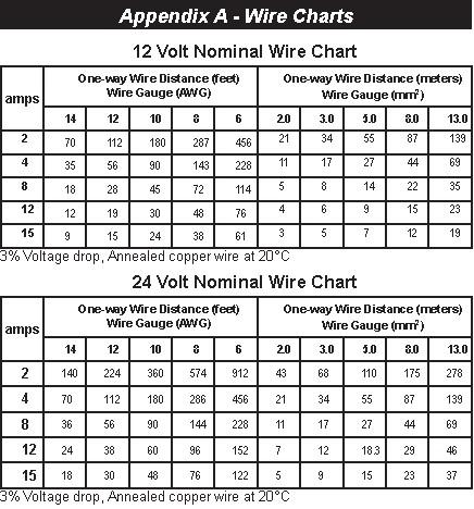
8 prevent cables from swaying when the vehicle is in motion. Unsecured cables create loose and resistive connections which may lead to excessive heating and/or fire. Step 1: Load Wiring The SMT load output connection will provide battery voltage to system loads such as lights, pumps, motors, and electronic devices. see Section 4.4 Load Control. Figure 4. Load wiring Connect load positive (+) and negative (-) load wires to the system load(s) or load distribution panel as shown in figure 4. Refer to the wire gauge chart of this manual for correct wire size. If required, the negative load connection may be earth grounded. Use appropriate gauge wire and proper grounding methods for the installation site. An in-line fuse holder should be wired in series in the load positive (+) wire as shown. Do not insert a fuse at this time. If wiring the load connection to a load distribution panel, each load circuit should be fused separately. the total load draw should not exceed the 25A a load rating. Step 2: Battery Wiring
9 Figure 5. Battery wiring. Before connecting the battery, measure the battery voltage. it must be over 7 volts to power the controller. For 24 volt systems, the battery voltage must be greater than 15.5 volts to properly detect a 24V battery. the 12/24 volt battery detection is automatic and the check is only performed at start-up. Connect the battery to the SMT.refer to the wire gauge chart on page 24 of this manual for correct wire size. If required, the negative battery connection may be earth grounded. Use appropriate gauge wire and proper grounding methods for the installation site. Wire an in-line fuse holder no more than 6 inches (150mm) from the battery positive terminal. Do not insert fuse at this time. Step 3: Solar Wiring WARNING: Risk of electric shock! Exercise caution whenhandling solar wiring. The solar array high voltage output can cause severe shock or injury. Cover modules from the sun before installing solar wiring. The SMT can accept 12 V, 24V nominal off-grid solar module arrays. grid-tie solar module(s) may be used if the open circuit voltage (Voc) does not exceed the SMT 75 Volt maximum solar input rating. the solar module(s) nominal voltage must be equal to or greater than the nominal battery voltage. For 24 V systems, a 24 V nominal solar array must be used.
 to the SMT refer to the wire gauge chart on page 17 of this manual for correct wire size.")

10 Figure 6. Solar input wiring. Connect the solar module(s) to the SMT refer to the wire gauge chart on page 17 of this manual for correct wire size. If required, the negative solar connection may be earth grounded. Use appropriate gauge wire and proper grounding methods for the installation site. Step 4: Confirm Wiring Double-check the wiring in steps 1 through 3. Confirm correct polarity at each connection. Verify that all seven (7) SMT power terminals are tightened. Figure 7. System Wiring Review
11 Step 5: Install Fuses Install a 40 amp DC-rated fuse in each fuse holder in the following order: 1. Load circuit 2. Battery circuit Step 6: Confirm Power-up The SMT should begin the power-up LED sequence when battery power is applied. observe that the Battery status LEDs blink in sequence one time. If the SMT does not power up or a fl ashing LED, refer to Section 5.0 Troubleshooting 4.1 LED Indications STATUS LED The Status LED indicates charging status and any existing solar input error conditions. The Status LED is on when charging during the day and off at night. The Status LED will flash red whenever an error condition(s) exists. Table 2 lists the Status LED indications. Color Indication Operating State None Off Error Green Flashing Charging Table 2. Status LED definitions BATTERY SOC LEDS Three (3) battery state of charge LEDs indicate the level of charge on the battery. The SOC indication is based on battery voltage setpoints alone, which only provides An approximation of the actual state of charge of the battery. Table 3 lists the SOC LED indications.
12 SOC LED Indication Battery Status Load Status Yellow Close to the green indicator lights 70% Load On Yellow The middle light of the three yellow indicator lights 25-75% Load On Yellow The most left indicator lights <25% Load On Yellow The most left indicator lights and flashes <10% Load On Table 3. Battery SOC LED definitions CAUTION: An error condition exists if multiple Battery SOC LEDs are flashing. See Section 5.0 Error Indications. 4.2 MPPT Technology The SMT utilizes Morningstar s TrakStar Maximum Power Point Tracking technology to extract maximum power from the solar module(s). The tracking algorithm is fully automatic and does not require user adjustment. Trakstar technology will track the array maximum power point voltage (Vmp) as it varies with weather conditions, ensuring that maximum power is harvested from the array through the course of the day. Current Boost In many cases, MPPT technology will boost the solar charge current. For example, a system may have 2 Amps of solar current flowing into the SMT and 5 Amps of charge current flowing out to the battery. The SMT does not create current! Rest assured that the power into the SMT is the same as the power out of the SMT. Since power is the product of voltage and current (Volts x Amps), the following is true: (1) Power Into the SMT = Power Out of the SMT (2) Volts In x Amps In = Volts Out x Amps Out * assuming 100% efficiency. losses in wiring and conversion exist. If the solar module s Vmp is greater than the battery voltage, it follows that the battery current must be proportionally greater than the solar input current so that input and output power are balanced. The greater the difference between the maximum power voltage and battery voltage, the greater the current boost. Current boost can be substantial in systems where the solar array is of a higher nominal voltage than the battery as described in the next section.

13 High Voltage Strings and Grid-tie Modules Another benefit of MPPT technology is the ability to charge 12 Volt or 24 Volt batteries with solar arrays of higher nominal voltages. A 12V battery bank can be charged with a 12 V, 24 V, or 36 V nominal off-grid solar array. Certain grid-tie solar modules may also be used as long as the solar array open circuit voltage (Voc) rating will not exceed the MPPT 75 V maximum input voltage rating at worst-case (coldest) module temperature. The solar module documentation should provide Voc vs. temperature data. Higher solar input voltage results in lower solar input current for a given input power. High voltage solar input strings allow for smaller gauge solar wiring. This is especially helpful for systems with long wiring runs between the solar array and the SMT. An Advantage Over Traditional Controllers Traditional controllers connect the solar module directly to the battery when recharging. This requires that the solar module operate in a voltage range that is below the module s Vmp. In a 12 V system for example, the battery voltage may range from Vdc but the module s Vmp is typically around 17 V. Figure 8 shows a typical current vs. voltage output curve for a nominal 12V off-grid module. The array Vmp is the voltage where the product of current and voltage (Amps x Volts) is greatest, which falls on the knee of the solar module I-V curve as shown in Figure 8. Because Traditional controllers do no operate at the Vmp of the solar array, energy is wasted that could otherwise be used to charge the battery and power system loads. The greater the difference between battery voltage and the Vmp of the module, the more energy is wasted. MPPT technology will always operate at the Vmp resulting in less wasted energy compared to traditional controllers. 4.3 Battery Charging Information The SMT has a 4-stage battery charging algorithm for rapid, efficient, and safe battery charging. Figure 9 shows the sequence of the stages.

14 Bulk Charge In this stage, the battery voltage has not yet reached absorption voltage and 100% of available solar power is used to recharge the battery. Absorption When the battery has recharged to the Absorption voltage setpoint, constant-voltage regulation is used to prevent heating and excessive battery gassing. Float After the battery is fully charged the SMT reduces the battery voltage to a float charge which is sometimes called a trickle charge. Depending on battery history, the battery remains in the absorption stage for 3 or 4 hours before transitioning to the float stage. 4.4 Load Control Information The primary purpose of the load control function is to disconnect system loads when the battery has discharged to a low state of charge and reconnect system loads when the battery is sufficiently recharged. System loads may be lights, pumps, motors, DC appliances, and other electronic devices. The total current draw of all loads must not exceed the SMT 25 Amp maximum load rating. CAUTION: Do not wire an AC inverter of any size to the load terminals of the SMT. Damage to the load control circuit may result. Wire inverters directly to the battery or battery bank. Low Voltage Discounted (LVD) As the battery discharges, the Battery Status indicator will have appropriate instructions. The flashing yellow indication is a warning that a low voltage disconnect event will occur soon. The amount of time between a yellow SOC indication and load disconnect will depend on many factors including: rate of discharge (amount of load draw) capacity of the battery
15 health of the battery LVD setpoint If the battery discharges to the LVD setpoint the load will disconnect. General Load Control Notes A 15 V maximum regulation voltage limit exists for all battery types. This limit ensures that the battery and load terminal voltages will never exceed 15 V/30 V. This protects certain DC loads that may be damaged by high input voltage. Do not wire multiple SMT load outputs together in parallel to power DC loads with a current draw greater than 25A. Equal current sharing cannot be guaranteed and an over-load condition will likely occur on one or more controllers. Exercise caution when connecting loads with specific polarity to a live load circuit. A reverse polarity connection may damage the load. Always double check load connections before applying power. 4.5 Protections Solar Overload (No LED indication) The SMT will limit battery current to the 25 Amp maximum rating. An over-sized solar array will not operate at peak power. The solar array should be less than the SMT nominal max. input power rating for optimal performance. See Section 6.0 Technical Specifications for more information. Load Overload If the load current exceeds the maximum load current rating, the SMT will disconnect the load. The greater the overload the faster the load will be disconnected. A small overload could take a few minutes to disconnect. Load Short Circuit Fully protected against load wiring short-circuits. After two (2) automatic load reconnect attempts (10 seconds between each attempt), the fault must be cleared by removing and reapplying power. High Voltage Input If the solar input open circuit voltage (Voc) exceeds the 75 volt maximum rating the array will remain disconnected until the Voc falls safely below the maximum rating. Battery Reverse Polarity Fully protected against reverse battery connection. No damage to the controller will result. Correct the miswire to resume normal operation. High Temperature The heatsink temperature has exceeded safe limits and the load is disconnected. The load will
16 automatically reconnect when the heatsink cools to a safe temperature. 4.6 Inspection and Maintenance The following inspections and maintenance tasks are recommended at least two times per year for best controller performance. Tighten all terminals. Inspect for loose, broken, or corroded connections. Verify that all wire clamps and tie-downs are secure. Check that the controller is mounted in a clean, protected environment; free of dirt, insects, nests, and corrosion. If applicable, check enclosure ventilation and air flow holes for obstructions. Verify LED indication is consistent with the present system conditions. Verify that the Remote Temperature Sensor (if used) is securely attached to the RTS terminals. 5.1 Error Indications Status LED Error Indications Damaged heatsink temp. sensor Solid Red Damaged input MOSFETs Solid Red Firmware Error Solid Red Battery Status LED Error Indications High Temperature Disconnect Solid Red External Wiring Error Solid Red Load Overcurrent Solid Red Load Short Circuit Solid Red 5.2 Common Problems Problem: No LED indications Solution: With a multi-meter, check the voltage at the battery terminals on the SMT. Battery voltage must be at least 7V to power the SMT. Problem: The SMT is not charging the battery. Solution: If the Status LED is solid,see Section 5.1 Error Indications. If the Status LED is off,measure the voltage across the Solar input terminals of the SMT. Input voltage must be greater than battery voltage. Check fuses and solar wiring connections. Check solar array for shading.
17 Electrical Nominal system voltage 12 or 24 Vdc Max. battery current 25 A Battery voltage range 7 V 36 V Max. solar input voltage 75 V Nominal Max. Input Power 300W S elf-consumption 35 ma Accuracy 1.0 % Voltage 2.0 % Current 2.0 % Environmental Ambient Temperature Range Storage temperature Humidity Enclosure -40 C to +60 C -55 C to +100 C 100% N.C. IP 10 (indoor) Mechanical Power terminals wire size (max.) Solid #6 AWG / 16 mm2 Multistrand #6 AWG / 16 mm2 Fine strand #8 AWG / 10 mm2 Terminal Diameter in / 5.4 mm Power terminals torque (max.) 35 in-lb / 4 Nm RTS terminals wire size (max.) Wire gauge (min) #22 AWG / 0.3 mm2 Wire gauge (max) #12 AWG / 3.0 mm2 RTS terminals torque (max.) 0.4 Nm / 3.5 in-lb Dimensions see inside front cover Weight 1.3 lbs / 0.60 kg
18 Efficiency and Deratings SMT Efficiency 12 Volt Figure 10. SMT 12 Volt Efficiency Curves SMT Efficiency 24 Volt Figure 11. SMT 24 Volt Efficiency Curves
19 SMT Efficiency 24 Volt
20
WITH TRAKSTAR TM MPPT TECHNOLOGY. Installation and Operation Manual. Model: SS-MPPT-15L
 SUNSAVER MPPT TM WITH TRAKSTAR TM MPPT TECHNOLOGY Installation and Operation Manual MAXIMUM POWER POINT TRACKING Model: SS-MPPT-15L 1098 Washington Crossing Road Washington Crossing, PA 18977 USA www.morningstarcorp.com
WITH TRAKSTAR TM MPPT TECHNOLOGY. Installation and Operation Manual MAXIMUM POWER POINT TRACKING. Model: SS-MPPT-15L
 SUNSAVER MPPT TM WITH TRAKSTAR TM MPPT TECHNOLOGY Installation and Operation Manual MAXIMUM POWER POINT TRACKING Model: SS-MPPT-15L 1098 Washington Crossing Road Washington Crossing, PA 18977 USA www.morningstarcorp.com
LS0512 Solar Charge Controller
 LandStar LS0512 Solar Charge Controller Nominal system voltage Maximum PV input voltage Nominal charge / discharge current 12VDC 35V 5A Contents 1 Important Safety Information... 1 2 General Information...
LS0512R Solar Light Controller
 LandStar LS0512R Solar Light Controller Nominal system voltage Maximum PV input voltage Nominal charge / discharge current 12VDC 35V 5A Contents 1 Important Safety Information... 1 2 General Information...
TRACER 1206/1210/1215
 TRACER 1206/1210/1215 Maximum Power Point Tracking Controller Installation and Operation Manual Thanks very much for selecting our products! This manual offers important information and suggestions with
INSTRUCTION MANUAL EPSOLAR. Tracer-3215RN. Maximum Power Point Tracking Solar Charge Controller
 EPSOLAR Utility model patent NO. 201120064092.1 Tracer-3215RN Maximum Power Point Tracking Solar Charge Controller INSTRUCTION MANUAL Thank you very much for selecting our product! This manual offers important
INSTRUCTION MANUAL EPSOLAR. Tracer-4215RN. Maximum Power Point Tracking Solar Charge Controller
 EPSOLAR Utility model patent NO. 201120064092.1 Tracer-4215RN Maximum Power Point Tracking Solar Charge Controller INSTRUCTION MANUAL Thank you very much for selecting our product! This manual offers important
Duo Battery Charge Controller
 Duo Battery Charge Controller RENOGY 10A 20A Pulse Width Modulation Solar Charge Controller Manual 1 2775 E. Philadelphia St., Ontario CA 91761 1-800-330-8678 Version: 1.2 Important Safety Instructions
MPPT Solar Charge Controller
 MPPT Solar Charge Controller TRACER1206,TRACER1210,TRACER1215 10 AMP 12V/24V auto switch INTELLIGENT SOLAR CHARGE CONTROLLER INSTALLATION AND OPERATION MANUAL TRACER Dimensions Specification Summary System
The Traveler Series: Wanderer
 The Traveler Series: Wanderer RENOGY 30A PWM Charge Controller Manual 2775 E. Philadelphia St., Ontario, CA 91761 1-800-330-8678 1 Version: 2.3 Important Safety Instructions Please save these instructions.
The Traveler Series: Adventurer
 The Traveler Series: Adventurer RENOGY 30A Flush Mount Charge Controller Manual 2775 E. Philadelphia St., Ontario, CA 91761 1-800-330-8678 Version: 2.2 Important Safety Instructions Please save these instructions.
The Traveler Series: Wanderer
 The Traveler Series: Wanderer RENOGY 30A Charge Controller Manual 2775 E. Philadelphia St., Ontario, CA 91761 1-800-330-8678 Version: 2.0 Important Safety Instructions Please save these instructions. This
10A / 15A / 20A Solar Charge Controller. PU1024 / PU1524 / PU2024 series INSTRUCTION MANUAL
 10A / 15A / 20A Solar Charge Controller PU1024 / PU1524 / PU2024 series INSTRUCTION MANUAL Dear Customer, Thank you very much for choosing our product. This manual contains important information about
3.1 General Information
 1.0 Important Safety Information 2.0 General Information 2.1 Overview 2.3 Features 4 5 5 5 3.0 Installation 3.1 General Information 3.2 Wiring 4.0 Operation 4.1 MPPT Technology 13 4.2 Battery Charging
NSTHAI. Solar Light Controller
 NSTHAI Design patent NO.: 201130028317.3 Utility model patent NO.:201120064092.1 NSC2024R (LS2024R) Solar Light Controller INSTRUCTION MANUAL Thank you very much for selecting our product! This manual
Installation and Operation Manual. Dual Battery Charging Solar Controller. for RVs, Caravans, and Boats. Ratings. Rated Solar Current 25 Amps
 SUNSAVER DUO TM Installation and Operation Manual. Dual Battery Charging Solar Controller for RVs, Caravans, and Boats.. Ratings Nominal Voltage 12 Volts Rated Solar Current 25 Amps 1098 Washington Crossing
LS1024R / LS1524R / LS2024R. Solar Light Controller INSTRUCTION MANUAL
 EPSOLAR Design patent NO.: 201130028317.3 Utility model patent NO.: 201120064092.1 LS1024R / LS1524R / LS2024R Solar Light Controller INSTRUCTION MANUAL Thank you very much for selecting our product! This
User Manual. Energy charged in battery. 30% than conventional solar charger. Solar charge controller
 User Manual Energy charged in battery MPPT Solar charge controller 30% than conventional solar charger SUN-MPPT-3015A SUN-MPPT-5015A 1 2 List: Dimensions in Millimeters [Inches]... 4 1.0 Important Safety
The Traveler Series TM : Adventurer
 The Traveler Series TM : Adventurer 30A PWM Flush Mount Charge Controller w/ LCD Display 2775 E. Philadelphia St., Ontario, CA 91761 1-800-330-8678 Version: 3.4 Important Safety Instructions Please save
Rover Series. Rover 20A 40A Maximum Power Point Tracking Solar Charge Controller
 Rover Series Rover 20A 40A Maximum Power Point Tracking Solar Charge Controller 0 2775 E. Philadelphia St., Ontario, CA 91761 1-800-330-8678 Version 1.5 Important Safety Instructions Please save these
PV Generation System. Solar Charge Controller SPECIFICATION
 PV Generation System Solar Charge Controller SPECIFICATION Home application type Version: V5.0 Thank you very much for selecting our product! This manual offers important information and suggestions with
Eclipse Solar Suitcase
 Eclipse Solar Suitcase Renogy 100W 200W 2775 E. Philadelphia St., Ontario, CA 91761 1-800-330-8678 Version 1.0 Important Safety Instructions Please save these instructions. This manual contains important
SCC-MPPT Solar Charge Controller
 Table 4: Alarm point for low battery voltage table Model Alarm point SCC-MPPT-300 10.5 V SCC-MPPT-600 21.0 V Table 5: Charging hour table for reference Battery Capacity To 90% capacity @ 25A charging current
EPEVER. LS-E Series. Solar Charge Controller USER MANUAL
 EPEVER LS-E Series Solar Charge Controller USER MANUAL LandStar LS-E Series Solar Charge Controller Nominal System Voltage Maximum PV Input Voltage Nominal Charge/Discharge Current LS0512E/LS1012E LS1024E/LS2024E
User Manual. Solar Charge Controller 3KW
 User Manual Solar Charge Controller 3KW 1 CONTENTS 1 ABOUT THIS MANUAL... 3 1.1 Purpose... 3 1.2 Scope... 3 1.3 SAFETY INSTRUCTIONS... 3 2 INTRODUCTION... 4 2.1 Features... 4 2.2 Product Overview... 5
Solar Charge Controller
 Table 3: Charging voltage for 4 types of battery Battery Type Battery Type Code SC-600W MPPT Bulk Voltage Floating Voltage Vented 01 28.6 V 26.4 V Sealed 02 28.6 V 26.8 V Gel 03 28.6 V 27.4 V NiCd 04 28.6
SCC-MPPT Solar Charge Controller
 Table 3: Charging voltage for 4 types of battery Battery Battery 12V battery system 24V battery system Type Type Code Bulk Floating Bulk Floating Vented 01 14.3 V 13.2 V 28.6 V 26.4 V Sealed 02 14.3 V
SOLAR LIGHTING CONTROLLER SUNLIGHT MODELS INCLUDED IN THIS MANUAL SL-10 SL-10-24V SL-20 SL-20-24V
 SOLAR LIGHTING CONTROLLER OPERATOR S MANUAL SUNLIGHT MODELS INCLUDED IN THIS MANUAL SL-10 SL-10-24V SL-20 SL-20-24V 10A / 12V 10A / 24V 20A / 12V 20A / 24V 1098 Washington Crossing Road Washington Crossing,
SCC-MPPT Solar Charge Controller
 Solar Charge Controller Quick Guide 200W 300W 400W 600W 850W V. 2.2 1. Introduction solar charge controller uses PWM-based DSP controller to keep the batteries regulated and prevent batteries from overcharging
12/24 VOLT AUTOMATIC SOLAR CHARGE CONTROLLER
 12/24 VOLT AUTOMATIC SOLAR CHARGE CONTROLLER P/No.s SC320 & SC330 WARNING Please read these instructions completely prior to installation. Lead acid batteries can be dangerous. Ensure no sparks or flames
LS1024BP/ LS2024BP. Solar Charge Controller USER MANUAL
 EPSOLAR LS1024BP/ LS2024BP Solar Charge Controller USER MANUAL Thank you very much for selecting our product! This manual offers important information and suggestions with respect to installation, use
LS1024BP/ LS2024BP. Solar Charge Controller USER MANUAL
 EPSOLAR LS1024BP/ LS2024BP Solar Charge Controller USER MANUAL Thank you very much for selecting our product! This manual offers important information and suggestions with respect to installation, use
EcoBoost MPPT TM. Solar Charging System Controller. Installation, Operation and Maintenance Manual
 EcoBoost MPPT TM Solar Charging System Controller Installation, Operation and Maintenance Manual For the most recent manual revisions, see the version at: www.morningstarcorp.com www.morningstarcorp.com
MPPT Solar Charge Controller
 MPPT Solar Charge Controller Installation and Operation Manual Maximum Power Point Tracking Technology Content 1. IMPORTANT SAFETY INSTRUCTIONS......3 2. GETTING STARTED..... 5 3. INSTALLATION... 8 4.
User Manual Solar Charge Controller 3KW
 User Manual Solar Charge Controller 3KW Version: 1.3 CONTENTS 1 ABOUT THIS MANUAL... 1 1.1 Purpose... 1 1.2 Scope... 1 1.3 SAFETY INSTRUCTIONS... 1 2 INTRODUCTION... 2 2.1 Features... 2 2.2 Product Overview...
OD10 10A Outdoor Solar Charge Controller
 OD10 10A Outdoor Solar Charge Controller CHC-OD12-10 User s Manual Page 1 of 14 windynation Revision 2 Table of Contents 1.1 Features...3 1.2 Safety Information...4 1.3 Specifications...4 1.3.1 Electrical
PHOTOVOLTAIC SYSTEM CONTROLLERS SUNSAVER MODELS INCLUDED IN THIS MANUAL SS-6 / SS-6L SS-10 / SS-10L SS-10-24V / SS-10L-24V SS-20L SS-20L-24V
 PHOTOVOLTAIC SYSTEM CONTROLLERS OPERATOR S MANUAL SUNSAVER MODELS INCLUDED IN THIS MANUAL SS-6 / SS-6L SS-10 / SS-10L SS-10-24V / SS-10L-24V SS-20L SS-20L-24V 6A / 12V 10A / 12V 10A / 24V 20A / 12V 20A
MPPT Solar Charge Controller INSTRUCTION MANUAL
 MPPT Solar Charge Controller PTR Tracer AN Series (10A/20A/30A/40A 12V/24V) INSTRUCTION MANUAL Models: PTR1210AN / PTR2210AN PTR3210AN / PTR4210AN Important Safety Instructions This manual contains important
HQST 20A 30A 40A. MPPT Solar Charge Controller. User Manual
 HQST 20A 30A 40A MPPT Solar Charge Controller User Manual Important Safety Instructions Please reserve this manual for future review. This manual contains all instructions of safety, installation and operation
Solar Charge Controller
 AIMS Power www.aimscorp.net Solar Charge Controller Installation and Operation Manual AIMS POWER Headquarters 9550 Gateway Drive Reno, NV 89521 Tel:(775)359-6703 Fax:(775)359-6753 Email: Sales@aimscorp.net
Owner s Manual. Contents GP-PWM-30-SQ GP-PWM-30-SQ
 Owner s Manual Contents 1.0 Installation Overview... 2 2.0 Warnings... 2 3.0 Choosing a Location...3 4.0 Installation Instructions... 3 5.0 Operating Instructions...4 6.0 Frequently Asked Questions (FAQs)...6
Installation and Operating Instructions. MPPT Solar System Controller ISC3040
 Installation and Operating Instructions MPPT Solar System Controller ISC3040 ABOUT THIS MANUAL These operating instructions come with the product and should be kept with it as a reference to all user s
SK-10. Features. Solar Charge Controller User Manual. Important Safety Information
 SK-10 Solar Charge Controller User Manual 12V/24V 10Amp Dear Users: Thank you for selecting our product. Please read this manual carefully before you use this product. This product is of cutting edge design,
SCCP PWM Charge Controller/Load Manager Owner s Manual
 SCCP05-050 PWM Charge Controller/Load Manager Owner s Manual NOTE: Follow instructions in order. Charge batteries at least once a week. Use reducers to connect larger wires disconnect to terminals. battery
Owner s Manual. Contents GP-PWM-10-SQ
 Owner s Manual Contents 1.0 Installation Overview... 2 2.0 Warnings... 2 3.0 Choosing a Location... 3 4.0 Installation Instructions... 3 5.0 Operating Instructions... 4 6.0 Frequently Asked Questions (FAQs)...
Owner s Manual. Solar Controller GP-PWM-30
 Owner s Manual Solar Controller GP-PWM-30 1.0 Installation Overview 1.1 Introduction A Solar Controller (or Charge Controller / Regulator) is an essential component of your photovoltaic solar system. The
GV-4 Manual 4A / 50W IMPORTANT SAFETY INSTRUCTIONS SAVE THESE INSTRUCTIONS. Solar Charge Controller with Maximum Power Point Tracking.
 GV-4 Manual Solar Charge Controller with Maximum Power Point Tracking For models: GV-4-Pb-12V: 12V Lead-Acid/AGM/Gel/Sealed/Flooded http://genasun.com Genasun Inc. 1035 Cambridge st. Suite 16B Cambridge,
Installation and Operating Instructions. Solar System Controller ISC3020
 Installation and Operating Instructions Solar System Controller ISC3020 ABOUT THIS MANUAL These operating instructions come with the product and should be kept with it as a reference to all user s of
EPRC-ST Solar Charge Controller
 EPRC-ST Solar Charge Controller 10 AMP 12V/24V auto switch INTELLIGENT SOLAR LIGHTING CONTROLLER INSTALLATION AND OPERATION MANUAL Koneze Industrial Co., Ltd 2011-1-11 1 TABLE OF CONTENT 1. Data Sheet.......
GV-Boost Waterproof Manual
 GV-Boost Waterproof Manual Waterproof Voltage Boosting Solar Charge Controllers with Maximum Power Point Tracking For models: GVB-8-Pb-36V-WP: GVB-8-Pb-48V-WP: 36V Lead-Acid/AGM/Gel/Sealed/Flooded 48V
MPPT75HV MAXIMUM POWER POINT TRACKING SOLAR BATTERY CHARGE CONTROLLER
 MPPT75HV MAXIMUM POWER POINT TRACKING SOLAR BATTERY CHARGE CONTROLLER The Intronics Power Inc. MPPT75HV Solar Charge Controller continually tracks the maximum power point of the solar panel array, adjusting
12 VOLT 30 AMP DIGITAL SOLAR CHARGE CONTROLLER
 12 VOLT 30 AMP DIGITAL SOLAR CHARGE CONTROLLER User s Manual Congratulations on your Coleman solar product purchase. This product is designed to the highest technical specifications and standards. It will
Installation and operating instructions. Solar charge controller MPPT 10 A / 20 A Z Z
 Installation and operating instructions Solar charge controller MPPT 10 A / 20 A EN 1 Contents 1. About these instructions... 3 1.1 Applicability... 3 1.2 Users... 3 1.3 Description of symbols... 3 2.
Ningbo Star Solar Co.,Ltd Tel:(86) Fax:(86)
 Fax:(86)") Tracer MPPT Solar charge controller Tracer series 40A mppt solar controller adopts MPPT technology (Maximum Power Point Tracking). The advanced tracking algorithm make the solar panel operate at ideal
Tracer MPPT Solar charge controller Tracer series 40A mppt solar controller adopts MPPT technology (Maximum Power Point Tracking). The advanced tracking algorithm make the solar panel operate at ideal
DIN Rail UPS Model: DIN-UPS Installation/Operation Manual
 DIN Rail UPS Model: DIN-UPS 24-10 Installation/Operation Manual Table of Contents Section Page Section Page Quick Start 2 1) General Information 4 Materials Provided 4 Optional Equipment 4 2) Safety Information
Solar System Controller
 POWER FAULT 50 Amp MPPT Installation and Operating Instructions Solar System Controller ISC5040 ABOUT THIS MANUAL These operating instructions come with the product and should be kept with it as a reference
Pure Sine Wave Inverter Charger
 Pure Sine Wave Inverter Charger Renogy 1000W 2000W Pure Sine Wave Inverter Charger Manual 2775 E. Philadelphia St., Ontario, CA 91761 1-800-330-8678 Version 1.6 1 Important Safety Instructions Please save
Harness the Power of the Sun
 Harness the Power of the Sun Solar Controller / Battery Charger User s Manual Nominal Voltage: 12Volts Rated Solar Current: 30Amps / 40Amps Nominal Voltage: 12Volts / 24Volts Auto Rated Solar Current:
PV Charge Controller SBC-7108 / 7112 / 7120
 PV Charge Controller SBC-7108 / 7112 / 7120 User's Manual NOTE: Please note that features like LCD read out of AH logging of 3 days (see Section 3.3) and 10 Night-light mode (see Section 4.3) are available
BlueSolar charge controller MPPT 100/30
 Manual EN Handleiding NL Manuel FR Anleitung DE Manual ES Användarhandbok SE Appendix BlueSolar charge controller MPPT 100/30 1. General Description 1.1 Charge current up to 30 A and PV voltage up to 100
SOLAR INVERTER/CHARGER 1000VA/1500VA/2000VA. Appliances. PC TV Light Electricfan
 SOLAR INVERTER/CHARGER SOLAR INVERTER/CHARGER 1000VA/1500VA/2000VA Appliances 420-00300-02 PC TV Light Electricfan Table Of Contents GENERAL PRECAUTIONS... 1 PERSONNEL PRECAUTIONS... 1 INTRODUCTION...
SBC V In-Car Charger Dual Input (Solar MPPT & DC)
") SBC-5926 12V In-Car Charger Dual Input (Solar MPPT & DC) Operation manual Keep this manual in a safe place for quick reference at all times. This manual contains important safety and operation instructions
SBC-5926 12V In-Car Charger Dual Input (Solar MPPT & DC) Operation manual Keep this manual in a safe place for quick reference at all times. This manual contains important safety and operation instructions
KIT-STCS60D KIT-STCS100D Solar Suitcase 60W and 100W Owner s Manual
 KIT-STCS60D KIT-STCS100D Solar Suitcase 60W and 100W Owner s Manual RNG Group Inc. (Renogy) 14288 Central Ave., Suite A Chino, CA 91710 1-800-330-8678 Product Description The Renogy Solar Suitcases combine
User Manual. UPower Series. Inverter/charger
 UPower Series Inverter/charger User Manual Models: UP1000-M3212/UP1000-M3222 UP1500-M3222/UP2000-M3322 UP3000-M3322/UP3000-M2142 UP3000-M6142/UP3000-M6322 UP5000-M6342/UP5000-M8342 UP5000-M10342 Important
PV Charge Controller SBC-6108 / 6112 / 6120 / 6130
 PV Charge Controller SBC-6108 / 6112 / 6120 / 6130 User's Manual Table of Contents Precautions and Specifications 1 1. Introduction 2 2. Control and Indicator 2 3. Installation and Indication 3 3.1 Connection
User s Manual. Automatic Switch-Mode Battery Charger
 User s Manual Automatic Switch-Mode Battery Charger IMPORTANT Read, understand, and follow these safety rules and operating instructions before using this battery charger. Only authorized and trained service
Installation and Operating Instructions. Solar System Controller ISC3030
 Installation and Operating Instructions Solar System Controller ISC3030 ABOUT THIS MANUAL These operating instructions come with the product and should be kept with it as a reference to all user s of the
Solar Charge Controller INSTRUCTION MANUAL
 NSTHAI ViewStar series Solar Charge Controller INSTRUCTION MANUAL Thank you very much for selecting our product! This manual offers important information and suggestions with respect to installation, use
1. General Description
 Manual BlueSolar charge controllers MPPT 150/45-Tr MPPT 150/45-MC4 MPPT 150/60-Tr MPPT 150/60-MC4 MPPT 150/70-Tr MPPT 150/70-MC4 MPPT 150/85-Tr MPPT 150/85-MC4 MPPT 150/100-Tr MPPT 150/100-MC4 1. General
Operating Manual MP-3739
 Operating Manual MP-3739 1 About this manual These operating instructions come with the product and should be kept for the life of the product for proper installation and usage. Read these operating instructions
Solar Controller / Battery Charger User s Manual
 Solar Controller / Battery Charger User s Manual 1 Congratulations! You have made an excellent choice by purchasing this high quality KORR PWM solar controller which has been manufactured to the highest
Solar System Controller. Installation and Operation Manual. Solar Battery Charger with TrakStar TM Maximum Power Point Tracking Technology
 TRISTAR MPPT TM Solar System Controller Installation and Operation Manual Solar Battery Charger with TrakStar TM Maximum Power Point Tracking Technology MAXIMUM POWER POINT TRACKING 8 Pheasant Run Newtown,
MB A 12V/24V DC PROGRAMMABLE DUAL BATTERY ISOLATOR
 MB-3688 120A 12V/24V DC PROGRAMMABLE DUAL BATTERY ISOLATOR User Manual Warning and Precautions MB-3688 is built with corrosion resistant material and the main electronic assembly is well sealed inside
User manual. Solar Hybrid 1-5KVA. Uninterruptible Power Supply / Charger
 User manual Solar Hybrid 1-5KVA Uninterruptible Power Supply / Charger All rights reserved. The information in this document is subject to change without notice. Thank you for purchasing this series UPS.
User Manual 1KVA-5KVA INVERTER / CHARGER
 User Manual 1KVA-5KVA INVERTER / CHARGER Version: 1.7 Table Of Contents ABOUT THIS MANUAL... 1 Purpose... 1 Scope... 1 SAFETY INSTRUCTIONS... 1 INTRODUCTION... 2 Features... 2 Basic System Architecture...
IMPORTANT. Always connect the batteries first. Use for 12V battery system only 12V (36 cells) solar panel array.
 solar panel array.") EN Appendix Manual IMPORTANT Always connect the batteries first. Use for 12V battery system only 12V (36 cells) solar panel array. Use for 24V battery system only 24V (72 cells) solar panel array. BlueSolar
EN Appendix Manual IMPORTANT Always connect the batteries first. Use for 12V battery system only 12V (36 cells) solar panel array. Use for 24V battery system only 24V (72 cells) solar panel array. BlueSolar
Battery Power Inverters
 Battery Power Inverters Renogy 500W 1000W 2000W Pure Sine Wave Inverter Manual 2775 E. Philadelphia St., Ontario, CA 91761 1-800-330-8678 1 Version 1.4 Important Safety Instructions Please save these instructions.
Art. No. EC-315. Art. No. EC-330. Art. No. EC-340 SWITCH-MODE BATTTERY CHARGER CONTENTS IMPORTANT SAFETY PRECAUTIONS... 2
 SWITCH-MODE BATTTERY CHARGER CONTENTS IMPORTANT SAFETY PRECAUTIONS... 2 DESCRIPTION AND FEATURES... 3 CHARGING STAGES... 4 Art. No. EC-315 Art. No. EC-330 Art. No. EC-340 PROTECTIONS... 5 INSTALLATION...
AC CONVERTER / BATTERY CHARGER
 AC CONVERTER / BATTERY CHARGER User s Manual MODEL #: CON120AC12/24VDC Listed to UL 458 and CSA 22.2 NO. 107.1 Standards Contents INTRODUCTION... 3 Important Safety Instructions... 3 1. General Description...
User Manual. Tracer AN series. MPPT Solar Charge Controller
 Tracer AN series MPPT Solar Charge Controller User Manual Models: Tracer5210AN/Tracer6210AN Tracer5415AN/Tracer6415AN Tracer8415AN/Tracer10415AN Tracer5420AN/Tracer6420AN Tracer8420AN/Tracer10420AN Important
Commander Series. RENOGY 60A Maximum Power Point Tracking Solar Charge Controller E. Philadelphia St., Ontario, CA
 Commander Series RENOGY 60A Maximum Power Point Tracking Solar Charge Controller 0 2775 E. Philadelphia St., Ontario, CA 91761 1-800-330-8678 Version 3.0 Important Safety Instructions Please save these
GV-Boost Manual. 8A Input / W IMPORTANT SAFETY INSTRUCTIONS SAVE THESE INSTRUCTIONS. Solar Charge Controllers with Maximum Power Point Tracking
 GV-Boost Manual Solar Charge Controllers with Maximum Power Point Tracking For models: GVB-8-Pb-12V: GVB-8-Pb-24V: GVB-8-Pb-36V: GVB-8-Pb-48V: GVB-8-Li-**.*V: 12V Lead-Acid/AGM/Gel/Sealed/Flooded 24V Lead-Acid/AGM/Gel/Sealed/Flooded
1KVA/ 2KVA/ 3KVA/ 4KVA/ 5KVA MS, LV MPPT INVERTER / CHARGER. User Manual. Version: 2.3
 1KVA/ 2KVA/ 3KVA/ 4KVA/ 5KVA MS, LV MPPT INVERTER / CHARGER User Manual Version: 2.3 Table Of Contents ABOUT THIS MANUAL... 1 Purpose... 1 Scope... 1 SAFETY INSTRUCTIONS... 1 INTRODUCTION... 2 Features...
DIN Rail UPS DC UPS/Battery Detection System Model: BDS-DIN-UPS Installation/Operation Manual
 DIN Rail UPS DC UPS/Battery Detection System Model: BDS-DIN-UPS 24-10 Installation/Operation Manual Table of Contents Section Page Section Page Quick Start 2 1) General Information 4 Materials Provided
OPTI-Solar PWM SERIES
 OPTI-Solar PWM SERIES SOLAR CHARGE CONTROLLER SC-45/ SC-60 Installation and Operation Manual USER MANUAL Solar Battery Charging Load Control Diversion Charge Control CONTENTS Specifications...I Chapter
Instruction of Solar Charge Controller. User s Manual
 Instruction of Solar Charge Controller User s Manual 12V/24V 10A/20A Dear Users: Thank you for selecting our product. Please read this manual carefully before you use this product. 0 The controller is
BZ Products Inc. U.S.A.
 BZ Products Inc. U.S.A. Model MPPT 150/50 Installation Instructions Thank you for choosing BZ Products MPPT 150/50. Made entirely in the USA, operation of this unit is fully automatic, and works in conjunction
MPPT Controller PVTS Series User Manual. User Manual. 800W-4000W Hybrid solar inverter. Version: 1.4
 User Manual 800W-4000W Hybrid solar inverter Version: 1.4 Table Of Contents ABOUT THIS MANUAL... 1 Purpose... 1 Scope... 1 SAFETY INSTRUCTIONS... 1 INTRODUCTION... 2 Features... 2 Basic System Architecture...
GP-MPPT-40. User Manual Go Power!
 User Manual Contents 1.0 Installation Overview 3 1.1 Introduction 3 1.2 Specifications 4 2.0 Warnings 5 3.0 Tools and Materials Needed 5 4.0 Choosing a Location 6 5.0 Choosing an Array 6 6.0 Installation
NLDC-25 Dual Battery Isolator and Charger
 Index Introduction Safety Information External features Preparing for Installation Fitting the NLDC-25 Universal Mounting Fixture Typical Installation diagram Installation steps Selecting battery type
ProStar TM. Solar Charging System Controller Installation, Operation, and Maintenance Manual. Languages: English, French, German, Spanish
 ProStar TM Solar Charging System Controller Installation, Operation, and Maintenance Manual Languages: English, French, German, Spanish For the most recent manual revisions, see the version at: www.morningstarcorp.com
Chapter 6. Batteries. Types and Characteristics Functions and Features Specifications and Ratings Jim Dunlop Solar
 Chapter 6 Batteries Types and Characteristics Functions and Features Specifications and Ratings 2012 Jim Dunlop Solar Overview Describing why batteries are used in PV systems. Identifying the basic components
Commander Series. RENOGY 60A Maximum Power Point Tracking Solar Charge Controller
 Commander Series RENOGY 60A Maximum Power Point Tracking Solar Charge Controller 0 2775 E. Philadelphia St., Ontario, CA 91761 1-800-330-8678 Version 2.1 Important Safety Instructions Please save these
Instruction of Solar Charge Controller. User s Manual
 Instruction of Solar Charge Controller User s Manual 12V/24V 30A Dear Users: Thank you for selecting our product. Please read this manual carefully before you use this product. The controller is for off-grid
CPS Energy Balancer. Version: 1.0
 CPS Energy Balancer Version: 1.0 CHINT POWER SYSTEMS AMERICA CO., LTD. Address: 700 International Parkway, Suite 102 Richardson, Texas Zip Code: 75081 Web: www.chintpower.com/na Email: americasales@chintpower.com
GVB-8 (Boost) Manual
 Manual") GVB-8 (Boost) Manual Solar Charge Controllers with Maximum Power Point Tracking For models: GVB-8-Pb-12V: 12V Lead-Acid/AGM/Gel/Sealed/Flooded GVB-8-Pb-24V: GVB-8-Pb-36V: GVB-8-Pb-48V: GVB-8-Pb-CV: 24V
GVB-8 (Boost) Manual Solar Charge Controllers with Maximum Power Point Tracking For models: GVB-8-Pb-12V: 12V Lead-Acid/AGM/Gel/Sealed/Flooded GVB-8-Pb-24V: GVB-8-Pb-36V: GVB-8-Pb-48V: GVB-8-Pb-CV: 24V
User Manual 1KVA-5KVA (PF1) INVERTER / CHARGER. Version: 1.0
 INVERTER / CHARGER. Version: 1.0") User Manual 1KVA-5KVA (PF1) INVERTER / CHARGER Version: 1.0 Table Of Contents ABOUT THIS MANUAL... 1 Purpose... 1 Scope... 1 SAFETY INSTRUCTIONS... 1 INTRODUCTION... 2 Features... 2 Basic System Architecture...
User Manual 1KVA-5KVA (PF1) INVERTER / CHARGER Version: 1.0 Table Of Contents ABOUT THIS MANUAL... 1 Purpose... 1 Scope... 1 SAFETY INSTRUCTIONS... 1 INTRODUCTION... 2 Features... 2 Basic System Architecture...
User Manual 5KVA/5KW INVERTER / CHARGER. Version: 1.3
 User Manual 5KVA/5KW INVERTER / CHARGER Version: 1.3 Table Of Contents ABOUT THIS MANUAL... 1 Purpose... 1 Scope... 1 SAFETY INSTRUCTIONS... 1 INTRODUCTION... 2 Features... 2 Basic System Architecture...
User Manual 1.5KVA-3KVA INVERTER / CHARGER. Version: 1.1
 User Manual 1.5KVA-3KVA INVERTER / CHARGER Version: 1.1 Table Of Contents ABOUT THIS MANUAL... 1 Purpose... 1 Scope... 1 SAFETY INSTRUCTIONS... 1 INTRODUCTION... 2 Features... 2 Basic System Architecture...
GVB-8 (Boost) Manual
 Manual") www.genasun.com GVB-8 (Boost) Manual Solar Charge Controllers with Maximum Power Point Tracking For models: GVB-8-Pb-12V: 12V Lead-Acid/AGM/Gel/Sealed/Flooded GVB-8-Pb-24V: 24V Lead-Acid/AGM/Gel/Sealed/Flooded
www.genasun.com GVB-8 (Boost) Manual Solar Charge Controllers with Maximum Power Point Tracking For models: GVB-8-Pb-12V: 12V Lead-Acid/AGM/Gel/Sealed/Flooded GVB-8-Pb-24V: 24V Lead-Acid/AGM/Gel/Sealed/Flooded