Hydraulic Shock Absorbers & Buffers
|
|
|
- Blaze Stevenson
- 5 years ago
- Views:
Transcription

1 Hydraulic Shock bsorbers & Buffers


2 Best Engineered for Energy bsorption OVERVIEW s manufacturing process speeds up in every industry for better productivity and production size is getting larger, needs for high performance hydraulic shock absorber are increasing in the market. IZMC has designed entirely new and innovative shock absorber, which achieved much higher output than a conventional shock absorber in rating by 200% upgrade and impact velocity up to 5m/sec. This new product is fully optimized for the best system performance and subjects to higher impact forces. This new design features a larger piston head diameter and a material balance to higher energy absorption. IZMC will provide better solutions for energy absorption, longer life cycles and high quality products. 02


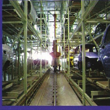
3 Hydraulic Shock bsorbers & Buffers PPLICTIONS utomotive robotics & Transfer lines Cranes : Bridge & Trolley, Container, Overheads Plastic bottle making Electronics and Semiconductor Glass forming equipments Pick & place robotics ssembling conveyors Material handling Printing machine Paper rolls Packing machinery Military Food and Beverage Textile Steel mills : Slab ingot, Crushing, Turntable Elevator Medical and Pharmaceutical equipments utomated storage and Retrieved system erospace Railway : Side & Front buffers Fixed rail end stop & Friction stop 03

4 SHOCK BSORBER Construction and principle Shock absorber consists of 5 major parts; Head, piston rod, body, adjustment dial and lock nut. Head is the direct contact part which is impacted by moving object and operated as a stopper to the body when cycle is completed. Piston rod transfers impact energy to the piston through the full stroke. Outside the body is fully threaded for easy installation at any position and for more heat dissipation. djustment dial is for the optimum operation by turning and setting knob to the various impact conditions. Lock nut is used to install and fix the shock absorbers tightly coupled with body thread on the machine. The Inside of shock absorber consists of piston, check valve, inner tube, multiple orifices, accumulator, return spring and oil. On impact, the piston rod is inserting into inner tube which causes pressure to seat check ball and close the check valve, and forces the oil in the chamber to flow through the orifice, generating damping force, to the opposite piston and accumulator which is compressed to compensate the volume of the piston rod. RECOIL SPRING BODY LOCK NUT DJUSTMENT DIL BERING SEL HED INNER TUBE CCUMULTOR PISTON ROD PISTON CHECK VLVE Energy absorption theory fter impact, coil spring forces check ball unseated and open the check valve to pass the oil into the oil chamber and recoil piston head and rod to its original position. When oil passes through the orifice, the impact energy is converted to the heat energy and dissipated to the atmosphere. 04


5 Hydraulic Shock bsorbers ORIFICE CHRCTERISTIC Single Orifice Single orifice type is called dashpot which has only one orifice on the piston as a hole or annular shape. t the beginning the shock force is very high and decreased rapidly. Force ORIFICE Multiple Orifices Through the stroke, the piston head closes one by one, which provides constant linear deceleration. DJUSTMENT TYPE djustment type shock absorber is for the optimum deceleration to turn and set properly adjustment dial to the impact conditions. Force ORIFICE SELF-COMPENSTING TYPE Self-compensating shock absorber is suitable for unvaried operating conditions and available in the range of effective weight for the best deceleration. 1 is a diagram of high speed and low propelling force. B1 is a diagram of low speed and high propelling force. 1 B1 Force ORIFICE 05

6 Hydraulic Shock bsorbers Symbols Useful Formulas Symbol Unit Description EK Nm Kinetic energy EW Nm Work energy ET Nm Total energy ETC Nm / h Total energy per hour FS N Impact force FP N Shock force WE kg Effective weight C Cycles / h Cycles per hour S m V m / s Impact velocity VD m / s Mass velocity PM kw Motor power D mm Inner diameter of cylinder Symbol Unit Description T Nm Torque H m Height W kg Weight P bar Operating pressure ω rad / s ngular velocity α ngle of incline Ⅰ kgm² Mass moment K m Radius of gyration RS m Mounting distance from pivot point µ Coefficient of friction g m / s² Gravitational acceleration a m / s² cceleration t s Time Description Symbol Formulas Impact force FS = ET / S / 0.8 Motor power FP = 3000 X PM / V Cylinder power FP = X D² X P Effective weight WE = 2 X ET / V² Velocity (free falling) Velocity (with acceleration) Velocity (w/o acceleration) V V V = 2 X g X H = 2 X D / t = D / t Deceleration a = V² / 2 / S Stopping time t = 2.6 X S / V Sizing Examples. Free Falling Mass B. Down Mass with Propelling Force Weight W = 600kg Weight W = 1,200kg S H Height H = 0.5m Cycles per hour Gravitational acceleration C = 60Cycles / h g = 9.81m / s² Propelling Force (Down) S H Impact velocity Inner diameter of cylinder Operating pressure Cycles per hour V = 1.8m / s D = 140mm P = 5bar C = 125Cycles / h 06 EK = W X g X H 600 X 9.81 X 0.5 2,943 Nm Select with EK : MD EW = W X g X S 600 X 9.81 X Nm ET = EK + EW 2, ,532 Nm ETC = ET X C 3,532 X ,896 Nm / h V = 2 X g X H 2 X 9.81 X m / s WE = 2 X ET / V² 2 X 3,532 / 3.13² 720 kg Selected with EK, ETC & WE : MD EK = W X V² / 2 1,200 X 1.8² / 2 1,944 Nm Select with EK : MD85-50 FP = X D² X P X 140² X 5 19,465 Nm + W X g + 1,200 X 9.81 EW = FP X S 19,465 X Nm ET = EK + EW 1, ,917 Nm ETC = ET X C 2,917 X ,656 Nm / h WE = 2 X ET / V² 2 X 2,917 / 1.8² 1,801 kg Select with EK, ETC & WE : MD85-50
 Impact velocity Inner diameter of cylinder Operating pressure Cycles per hour V = 2.")


![Horizontal Mass with Propelling Force [Motor] Propelling Force (Cylinder) S Propelling Force (Motor) S Weight Impact velocity Inner diameter of cylinder W = 300kg V = 1.](/docs-images/81/84233599/images/7-3.jpg "2m / s D = 50mm Operating pressure Cycles per hour P = 5bar C = 300Cycles / h Weight Impact velocity W = 1,300kg V = 1.")
7 Hydraulic Shock bsorbers C. Up Mass with Propelling Force D. Horizontal Mass without Propelling Force Weight W = 200kg H S Propelling Force (Up) Impact velocity Inner diameter of cylinder Operating pressure Cycles per hour V = 2.5m / s D = 150mm P = 5bar C = 180Cycles / h Weight Impact velocity W = 100kg V = 1.5m / s S Cycles per hour C = 600Cycles / h EK = W X V ² / X 2.5² / Nm Select with EK : MD45-50 FP = X D ² X P X 150² X 5 6,869 Nm - W X g X 9.81 EW = FP X S 6,869 X Nm ET = EK + EW Nm ETC = ET X C 968 X ,323 Nm / h WE = 2 X ET / V² 2 X 968 / 2.5² 310 kg Select with EK, ETC & WE : MD45-50 EK = W X V² / X 1.5² / Nm ET = EK + EW Nm ETC = ET X C 113 X ,800 Nm / h WE = 2 X ET / V² 2 X 113 / 1.5² 100 kg Select with EK, ETC & WE : SD25-25 E. Horizontal Mass with Propelling Force [Cylinder] F. Horizontal Mass with Propelling Force [Motor] Propelling Force (Cylinder) S Propelling Force (Motor) S Weight Impact velocity Inner diameter of cylinder W = 300kg V = 1.2m / s D = 50mm Operating pressure Cycles per hour P = 5bar C = 300Cycles / h Weight Impact velocity W = 1,300kg V = 1.6m / s Motor power Cycles per hour PM = 3kW C = 100Cycles / h EK = W X V² / X 1.2² / Nm Select with EK : SD36-25 FP = X D² X P X 50² X Nm EW = FP X S 981 X Nm ET = EK + EW Nm ETC = ET X C 241 X ,300 Nm / h WE = 2 X ET / V² 2 X 241 / 2.5² 334 kg Select with EK, ETC & WE : SD36-25 EK = W X V²/ 2 1,300 X 1.6² / 2 1,664 Nm Select with Ek : MD64-50 FP = 3,000 X PM / V 3,000 X 3 / 1.6 5,625 N EW = FP X S 5,625 X Nm ET = EK + EW 1, ,945 Nm ETC = ET X C 1,945 X ,500 Nm / h WE = 2 X ET / V² 2 X 1,945 / 1.6² 1,520 kg Select with EK, ETC & WE : MD
 X g 800 X sin(30) X 9.81 3,922 N EW = FP X S 3,922 X 0.")


8 Hydraulic Shock bsorbers G. Sliding Down Mass without Propelling Force H. Rotary Table Mass with Propelling Force K H RS Torque α S S ω 08 Weight W = 800kg Height H = 0.7m EK = W X H X g 800 X 0.7 X ,494 Nm Select with Ek : MD FP = W X sin(α) X g 800 X sin(30) X ,922 N EW = FP X S 3,922 X Nm ET = EK + EW 5, ,886 Nm ETC = ET X C 5,886 X ,600 Nm / h V = 2 X g X H 2 X 9.81 X m / s WE = 2 X ET / V² 2 X 5,886 / 3.7² 857 Nm / h Select with EK, ETC & WE : MD I. Swiveling Mass with Propelling Force ω S K Rs Weight ngular of incline Cycles per hour ngular velocity Mounting distance from pivot point α = 30 C = 100Cycles / h W = 50kg ω = 2.5rad / s Rs = 0.8m Radius of gyration K = 0.5m Inner diameter of cylinder Operating pressure Cycles per hour D = 40mm P = 5Bar C = 1,000Cycles / h I = W X K² 50 X 0.5² 13 kgm² EK = I X ω²/2 13 X 2.5² / 2 39 Nm Select with Ek : SD20-15 FP = X D ² X P X K / Rs X 40² X 5 X 0.5 / N T = FP X Rs 393 X Nm EW = FP X S 393 X Nm ET = EK + Ew Nm ETC = ET X C 45 X 1,000 45,000 Nm / h V = Rs X ω 2.5 X m / s WE = 2 X ET / V² 2 X 45 / 2² 22 kg Select with ET, ETC & WE : SD20-15 Weight ngular velocity Mounting distance from pivot point Weight Impact velocity ngular velocity W = 200kg ω = 2rad / s Rs = 0.5m I = W X K² 200 X 0.8² 128 kgm² EK = I X ω² / X 2² / Nm Select with Ek : SD36-25 FP = T / Rs 400 / N EW = FP X S 800 X Nm ET = EK + EW Nm ETC = ET X C 276 X ,600 Nm / h V = RS X ω 0.5 X 2 1 m / s WE = 2 X ET / V² 2 X 276 / 1² 552 kg Select with EK, ETC & WE : SD36-25 J. Swiveling Mass without Propelling Force ω W = 200kg V = 2m / s ω = 2.5rad / s K Radius of gyration Torque Cycles per hour Mounting distance from pivot point Radius of gyration Cycles per hour K = 0.8m T = 400Nm C = 350Cycles / h Rs = 0.6m K = 0.8m C = 200Cycles / h I = W X K² 200 X 0.8² 128 kgm² EK = I X ω² / X 2.5² / Nm Select with EK : SD36-50 FP = W X g X K / Rs 200 X 9.81 X 0.8 / 0.6 2,616 N EW = FP X S 2,616 X Nm ET = EK + Ew Nm ETC = ET X C 531 X ,200 Nm / h VD = V X Rs / K 2 X 0.6 / m / s WE = 2 X ET / VD² 2 X 531 / 1.5² 472 kg Select with EK, ETC & WE : SD36-50 S Rs


 enables to improve anti-corrosiveness for a long time usage.")

9 Hydraulic Shock bsorbers SD & SDS Series Description SD Series have an adjustment dial which can set 12 finite steps according to the impact velocity condition with advanced wide damping control range. SDS Series have an ability to adjust and control deceleration force by self compensating according to the impact velocity. SD & SDS Series have achieved 200% of energy absorption with expanded Effective Weight coverage compared with former products. SEL INNER TUBE BERING BERING SEL HED BODY HED PISTON CCUMULTOR PISTON ROD PISTON ROD CCUMULTOR RECOIL SPRING PISTON DJUSTMENT DIL RECOIL SPRING SD series SDS series Features ll outside thread-type body surface enables easy installation by fixing nuts tightly. Heat energy dissipation is enabled efficiently by the increased body surface area. Zn-Ni body coating (black color) enables to improve anti-corrosiveness for a long time usage. Stop collar is unnecessary if you re using steel head. The impact noise will be much reduced by using poly pad or urethane cap. Bearing is designed to protect seal by using special material and it guarantees a long durability. Velocity range : Standard : 0.1 ~ 5m/s Low Speed : OPTION Temperature coverage : -10 ~ 80 C Special : -40 ~ 120 C SD & SDS Series Ordering Information SD CS Body Thread Size CS : Stop Collar FR : Rectangular Flange LS : Side Load daptor MC : Clamp Mount SD : SERIES : djustable S : Non-djustable 09
10 SD 12/14 Series Engineering Data (mm) Max.Energy / Cycle Max.Energy / Hour (Nm) [Nm/h] Effective Weight (kg) Recoil Force (N) Ext. Com. Weight (g) SD12-10(B) , SD14-12(B) , Dimensions B C D E F G H M Dr SD12-10(B) Φ10.3 Φ M12 X 1.0 Φ4 SD14-12(B) Φ12 Φ M14 X 1.5 Φ4 E B C M ØDr D ØF ØG H : SW Steel head+hard PU button (B TYPE: Black) ccessories Stop Collar Side Load dapter Clamp Mount Lock Nut B1 B2 B3 B4 B5 C1 C2 C3 C4 C5 C6 D1 D2 D3 SD12-10(B) 20 8 Φ13.8 M12 X 1.0 SD14-12(B) Φ18 M14 X M12 X 1.0 M14 X 1.5 Φ Φ M12 X 1.0 M14 X 1.5 M5 X 18L M5 X 25L 14 M12 X M14 X B1 B2 B3 C1 C6:Bolt Size D1 2 C2 D3 3 4 B4 B5 C5 C3 C4 D2 Stop Collar Side Load dapter Clamp Mount Lock Nut 10
 SD16-12(B) 12 24 47,200 2-533 5 11.5 80 SD20-15(B) 15 56 58,000 4.5-1,244 8 19.6 145 SD25-25(B) 25 150 96,000 11.5-3,334 10.2 29.5 285 SD27-25(B) 25 150 96,000 11.5-3,334 10.2 29.5 305 Dimensions B C D E F G H M Dr SD16-12(B) 12 97 1.")
11 Hydraulic Shock bsorbers SD 16/20/25/27 Series Engineering Data (mm) Max.Energy / Cycle (Nm) Max.Energy/Hour (Nm / h) Effective Weight (kg) Recoil Force (N) Ext. Comp. Weight (g) SD16-12(B) , SD20-15(B) , , SD25-25(B) , , SD27-25(B) , , Dimensions B C D E F G H M Dr SD16-12(B) Φ13.6 Φ M16 X 1.5 Φ5 SD20-15(B) Φ17.6 Φ M20 X 1.5 Φ6 SD25-25(B) Φ22.6 Φ16 23 M25 X 1.5 Φ8 SD27-25(B) SD27-25F(B) Φ22.6 Φ16 23 M27 X 3.0 M27 X 1.5 Φ8 E B C M ØDr D H : SW Steel head+hard PU button (B TYPE: Black) ccessories Stop Collar Side Load dapter Clamp Mount Lock Nut B1 B2 B3 B4 B5 C1 C2 C3 C4 C5 C6 D1 D2 D3 SD16-12(B) Φ19 M16X M16X1.5 Φ M16X1.5 M6X25L 19 M16X1.5 6 SD20-15(B) Φ24 M20X M20X1.5 Φ M20X1.5 M6X30L 24 M20X1.5 6 SD25-25(B) Φ31.5 M25X M25X1.5 Φ M25X1.5 M6X35L 32 M25X1.5 8 SD27-25(B) SD27-25F(B) Φ31.5 M27X3.0 M27X M27X3.0 M27X1.5 Φ M27X3.0 M27X1.5 M6X35L 32 M27X3.0 M27X B1 B2 B3 2 3 ØF ØG C1 C6:Bolt Size D1 C2 D3 4 B4 B5 C5 C3 C4 D2 Stop Collar Side Load dapter Clamp Mount Lock Nut 11
12 SD 36 Series Engineering Data (mm) Max.Energy / Cycle Max.Energy / Hour (Nm) [Nm / h] Effective Weight (kg) Recoil Force (N) Ext. Comp. Weight (g) SD36-25(B) , , SD36-50(B) , , Dimensions B C D E F G H M Dr SD36-25(B) Φ31 Φ28 34 M36 X 1.5 Φ10 SD36-50(B) Φ31 Φ28 34 M36 X 1.5 Φ10 B C M D E ØDr ØF ØG H : SW Steel head+hard PU button (B TYPE: Black) ccessories Stop Collar Rectangular Flange Clamp Mount Lock Nut B1 B2 B3 B4 B5 B6 C1 C2 C3 C4 C5 C6 D1 D2 D3 SD36-25(B) Φ45 M36 X Φ M36 X 1.5 M6 X 45L 46 M36 X B1 B2 B5 C1 C6:Bolt Size D1 3 B3 B4 B6 C2 D3 4 Lock Slot C5 C3 C4 D2 Stop Collar Rectangular Flange Clamp Mount Lock Nut 12
13 Hydraulic Shock bsorbers SDS 10/12/14 Series Engineering Data (mm) Max.Energy / Cycle (Nm) Max.Energy / Hour (Nm / h) Effective Weight (kg) S M H Recoil Force (N) Ext. Comp. SDS10-08(B) , SDS12-10(B) , SDS14-15(B) , , Weight (g) Dimensions B C D E F G H M Dr SDS10-08(B) Φ8.6 Φ8.6 8 M10 X 1.0 Φ3 SDS12-10(B) Φ10.8 Φ M12 X 1.0 Φ4 SDS14-15(B) SDS14-15F(B) Φ11.8 Φ M14 X 1.5 M14 X 1.0 Φ4 B C D M ØDr E ØF ØG H : SW Steel head+hard PU button (B TYPE: Black) ccessories Stop Collar Clamp Mount Lock Nut C1 C2 C3 C4 C5 C6 D1 D2 D3 SDS10-08(B) 20 8 Φ12.8 M10 X M10 X 1.0 M4 X 16L 13 M10 X SDS12-10(B) 20 8 Φ13.8 M12 X M12 X 1.0 M5 X 18L 14 M12 X SDS14-15(B) SDS14-15F(B) Φ18 M14 X 1.5 M14 X M14 X 1.5 M14 X 1.0 M5 X 25L 19 M14 X 1.5 M14 X C1 C6:Bolt Size D1 3 C2 D3 4 C5 C3 C4 D2 Stop Collar Clamp Mount Lock Nut 13
14 SDS 20/25 Series Engineering Data (mm) Max.Energy / Cycle (Nm) Max.Energy / Hour (Nm / h) Effective Weight (kg) S M H Recoil Force (N) Ext. Comp. Weight (g) SDS20-20(B) , , SDS25-25(B) , , , Dimensions B C D E F G H M Dr SDS20-20(B) Φ17 Φ M20 X 1.5 Φ6 SDS25-25(B) SDS25-25F(B) Φ22 Φ16 25 M25 X 2.0 M25 X 1.5 Φ8 B C D M E ØDr ØF ØG H : SW Steel head+hard PU button (B TYPE: Black) ccessories Stop Collar Clamp Mount Lock Nut C1 C2 C3 C4 C5 C6 D1 D2 D3 SDS20-20(B) Φ24 M20 X M20 X 1.5 M6 X 30L 24 M20 X SDS25-25(B) SDS25-25F(B) Φ31.5 M25 X 2.0 M25 X M25 X 2.0 M25 X 1.5 M6 X 35L 32 M25 X 2.0 M25 X C1 C6:Bolt Size D1 2 3 C2 D3 4 C5 C3 C4 D2 Stop Collar Clamp Mount Lock Nut 14


15 Hydraulic Shock bsorbers MD Series Description MD Series is the medium & large size model. Piston is compressing the oil chamber as Piston Rod starts to move towards oil chamber when shock impact happens. It makes oil to flow forcedly from oil chamber to the piston back side or ccumulator through the groove at inner tube. During this oil flow by compressing, deceleration force will occur as the kinetic energy is transformed to the heat energy. This heat energy will be dissipated through the threaded body surface efficiently. fter impact load is removed, recoil spring will operate to return the piston rod to the original position. CCUMULTOR SEL INNER TUBE HED BERING PISTON ROD PISTON Features BODY DJUSTMENT DIL MD Series have an adjustment dial which can set 12 finite steps according to the impact velocity condition with an advanced wide damping control range. MD Series have achieved 200% of energy absorption with an expanded effective weight coverage compared with former products. ll outside thread-type body surface enables easy installation by fixing nuts tightly with it. Heat energy dissipation is enabled efficiently by the increased body surface area. Zn-Ni body coating (black color) enables to improve anti-corrosiveness for a long time usage. Stop collar is unnecessary if you re using steel head. The impact noise will be much reduced by using poly pad or urethane cap. Bearing is designed to protect seal by using special material and it guarantees a long durability. Velocity range : 0.3 ~ 5m/s Low Speed : OPTION Temperature coverage : Standard : -10 ~ 80 C Special : -40 ~ 120 C MD Series Ordering Information MD CS Body Thread Size MD : SERIES : djustable CS : Stop Collar CU : Urethane Cap FS : Square Flang CL : Lock Collar CR : Rod Clevis CE : End Clevis MC : Clamp Mount 15
16 MD 45 Series Engineering Data (mm) Max.Energy / Cycle (Nm) Max.Energy / Hour (Nm / h) Effective Weight (kg) Recoil Force (N) Ext. Comp. Weight (kg) MD , , MD , , , MD , , , B M45(42) X 1.5P Φ14 Clamp Mount C(Min/Max) D(Min/Max) Clevis Mount E Φ13 22 Lock Collar 23.5 Φ13 24 Φ50 Φ24 24 Φ Φ39 17 Φ42 Urethane Cap 19 End Clevis Rod Clevis 12 Dimensions B C D E 16 MD / / MD / / MD / /
 MD64-50 50 2,220 215,000 178-49, 330 61 133 3.2 MD64-100 100 4,400 316,000 352-97, 778 59 160 3.9 MD64-150 150 6,800 408,000 554-151,110 51 167 8.8 B M64 X 2.")
17 Hydraulic Shock bsorbers MD 64 Series Engineering Data (mm) Max.Energy/Cycle (Nm) Max.Energy/Hour (Nm/h) Effective Weight (kg) Recoil Force (N) Ext. Comp. Weight (kg) MD , , , MD , , , MD , , , B M64 X 2.0P Φ20 Clamp Mount C(Min/Max) D(Min/Max) Clevis Mount E Φ19 27 Lock Collar 42.5 Φ19 38 Φ74 Φ38 38 Φ Φ58 17 Φ62 Urethane Cap 32 End Clevis Rod Clevis 16 Dimensions B C D E MD / / MD / / MD / /
![www.izmac.co.kr MD 85 Series Engineering Data (mm) Max.Energy / Cycle Max.Energy / Hour (Nm) [Nm / h] Effective Weight (kg) Recoil Force (N) Ext. Comp.](/docs-images/81/84233599/images/18-5.jpg "MD 85-50 50 3,600 416,000 288-80,000 132 271 14 MD 85-100 100 7,200 745,000 576-160,000 125 327 20 MD 85-150 150 10,600 800,000 848-235,550 127 386 28 Weight (kg) B M85 X 2.")
18 MD 85 Series Engineering Data (mm) Max.Energy / Cycle Max.Energy / Hour (Nm) [Nm / h] Effective Weight (kg) Recoil Force (N) Ext. Comp. MD , , , MD , , , MD , , , Weight (kg) B M85 X 2.0 Φ25 Clamp Mount C(Min/Max) D(Min/Max) Clevis Mount E Φ19 27 Lock Collar 34 Φ19 38 Φ98 Φ38 38 Φ Φ75 20 Φ80 Urethane Cap Dimensions End Clevis Rod Clevis B C D E 18 MD / / MD / / MD / /


19 Hydraulic Shock bsorbers MD Series ccessories Stop Collar Clamp Mount 1 2 C1 Bolt:C6 3 C2 4 C5 C3 C4 Square Flange Lock Collar B1 B2 D1 B3 4-B5 D3 Lock slot B4 D2 Dimensions Stop Collar Square Flange Clamp Mount Lock Collar B1 B2 B3 B4 B5 C1 C2 C3 C4 C5 C6 D1 D2 D3 MD45-Series Φ56 M45 X 1.5P M45 X1.5P Φ M45 X 1.5P M8 X 60L Φ58 M45 X 1.5P 9 MD64- Series Φ75 M64 X 2.0P M64 X 2.0P Φ M64 X 2.0P M10 X 80L Φ80 M64 X 2.0P 11 MD85-Series Φ98 M85 X 2.0P M85 X 2.0P Φ M85 X 2.0P M12 X 100L Φ110 M85 X 2.0P 16 19


20 Hydraulic Buffers Description HDS series hydraulic buffers protect personnel and equipment safely. The robust and large bore buffers are so Custom-orificed to suit any impact load and speed that it provides a smooth constant deceleration throughout the stroke. To optimize its performance, buffers are individually simulated for various operating conditions and manufactured with over 90% of efficiency. Upon impact, the displacement of piston rod forces the oil through orifices on throttle port into the nitrogen chamber, generating oil pressure. The compressed nitrogen produces recoil force to extend piston rod to its original position. PISTON SEL GS CHMBER ORIFICE THROTTLE PORT BUFFER HED PISTON ROD FLOTING PISTON BODY RER MOUNT OIL CHMBER Features Deceleration : Custom - orificed design Piston Rod : Hardened, hard chrome plated Body : Epoxy painted Temperature : -20 ~ +80 C Special : -40 ~ +10 C Standard : OSH, ISE, CMM, DIN, FEM HDS Series Ordering Information HDS FR - BC Mount Type : mm Body Dia. HDS : Gas Return type C : Safety Cable CU : Urethane Cap B : Bellows FR : Rear Flange Mount FF : Front Flange Mount CR : Rod Clevis CE : End Clevis TF : Front & Rear Flange Mount RF : Rear Flange Front Foot Mount FM : Front & Rear Foot Mount 20


21 Hydraulic Buffers Hydraulic Buffers Symbols Useful Formulas Symbol Unit Description W kg Weight Symbol Unit Description r m Radius of rotation Maximum Shock Force F S = E T / S / F D WE kg Designed weight g m / s² Gravitational acceleration S = V² / 2 / d / 0.8 H m Height S m d m / s² Deceleration E K Nm Kinetic energy Deceleration d = V² / 2 / S / 0.8 V m / s Impact velocity E W Nm Work energy VE m / s Designed velocity E T Nm Total energy Deceleration Time t = 2.6 X S / V ω rad / s ngular velocity F D N Propelling force Ⅰ Nms² Mass moment F S N Impact force T Nm Torque η Efficiency rate Buffer Sizing rrangement Design Speed (VE) Design Weight (WE) V W V 2 2W V₁ + V₂ W₁ x W₂ W₁ + W₂ V₁ + V₂ 2 2 x W₁ x W₂ W₁ + W₂ 21


 + FD 188 / (0.4 X 0.8) + 20 607.")


 + FD 15.696 / (0.1 X 0.8) + 0 196.")
22 Hydraulic Buffers. Horizontal Mass without Propelling Force B. Horizontal Mass with Propelling Force [Motor] Weight W = 100ton Weight W = 160ton Impact velocity V = 0.5m/s Propelling force FD = 20kN Impact velocity V = 1.5m/s EK = W X V² / X0.5² / knm Select with Ek : HDS ET = EK + EW knm FS = ET / (S x η) + FD 12.5 / (0.2 X 0.8) kn Select with ET & FS : HDS EK = W X V² / X1.5² / knm Select with Ek : HDS EW = FD X S 20 X knm ET = EK + EW knm FS = ET / (S x η) + FD 188 / (0.4 X 0.8) kn Select with ET & FS : HDS C. Free Falling Mass D. Swiveling Mass with Propelling Force Torque r ω H S S Weight W = 4ton Height H = 0.3m Torque T = 200 Nm ngular velocity ω = 2 rad / s Radius of rotation r = 8 m Mass moment Ⅰ = 35 Nms² S = 0.2 m E K = W X g X H 4 X 9.81 X knm Select with Ek : HDS E W = W X g X S 4 X 9.81 X knm ET = EK + EW knm FS = ET / (S x η) + FD / (0.1 X 0.8) kn Select with ET & FS : HDS EK = ⅠX ω² / 2 35 X 2² / 2 70 knm Select with Ek : HDS EW = T X S / r 200 X 0.2 / 8 5 knm ET = EK + EW knm FS = ET / (S x η) + FD 75 / (0.2 X 0.8) kn Select with ET & FS : HDS
23 Hydraulic Buffers HDS 65 Series Engineering Data (mm) Max. Energy / Cycle (knm) Max. Shock Force (kn) Recoil Force (kn) Ext. Comp. Weight (kg) HDS Ø Rear Mount Ø65 B C Front Mount Ø Ø65 Ø16 Dimensions (mm) Rear Type B Front Type C Mounting Bolt Size HDS
24 HDS 85 Series Engineering Data (mm) Max. Energy / Cycle (knm) Max. Shock Force (kn) Recoil Force (kn) Ext. Comp. Weight (kg) HDS Ø Rear Mount Ø85 B C Ø Front Mount Ø85 Ø18 Dimensions (mm) Rear Type B Front Type C Mounting Bolt Size HDS

25 Hydraulic Buffers HDS 100 Series Engineering Data (mm) Max. Energy / Cycle (knm) Max. Shock Force (kn) Recoil Force (kn) Ext. Comp. Weight (kg) HDS Ø Rear Mount Ø100 B C 150 Front Mount Ø Ø100 Ø18 Dimensions (mm) Rear Type B Front Type C Mounting Bolt Size HDS

26 HDS 120 Series Engineering Data (mm) Max. Energy / Cycle (knm) Max. Shock Force (kn) Recoil Force (kn) Ext. Comp. Weight (kg) HDS Ø Rear Mount Ø120 B 220 Ø C Front Mount Ø120 Ø26 Dimensions (mm) Rear Type B Front Type C Mounting Bolt Size HDS
 HDS140-100 100 55 688 6 70 60-200 200 110 688 6 70 85-300 300 165 688 6 70 110-400 400 220 688 6 78 135-500 500 270 680 6 78 150-600 600 300 630 6 78")

27 Hydraulic Buffers HDS 140 Series Engineering Data (mm) Max. Energy / Cycle (knm) Max. Shock Force (kn) Recoil Force (kn) Ext. Comp. Weight (kg) HDS Ø Rear Mount Ø B C Ø Front Mount Ø140 Ø26 Dimensions (mm) Rear Type B Front Type C Mounting Bolt Size HDS


 Impact velocity : Max.")
28 Stacker Crane Buffers Description LDS series Stacker Crane Buffers are mainly used for automated storage system and are available in large capacity rated up to 930 knm with the stroke 1200mm. LDS series are designed to maintain comparatively low peak and recoil forces. So they are able to provide minimum resistance in normal operation and to offer smooth deceleration in emergency stop. Basically, LDS series are similar with HDS series in operating principle. However as the nitrogen volume is considerably greater than displaced oil volume, it compresses the nitrogen slightly and produces low recoil force. pplication Stacker cranes, Small over head cranes, utomotive production lines, Theme park riders Features Deceleration : Custom orifice Recoil force : Low peak and recoil force Piston rod : Hardened, hard chrome plated Cylinder : Zinc plated Temperature : -20 ~ + 80 (Normal type) -40 ~ +100 (Special type with Special seal and oil) Impact velocity : Max. 6 m/s (Special piston rod : Hardened steel) Standard : OSH, ISE, CMM, DIN, FEM Option : Protective bellows, Safety cable, Urethane cap, Large cap LDS Series Ordering Information LDS FM - B LD : MODEL Bore DI'(mm) (mm) B : Bellows C : Safety cable RM : Rear flange & Front mount FM : Front & Rear mount FF : Front Flange FR : Rear Flange FR : Rear Flange RM : Rear flange & Front mount B : Bellows FF : Front Flange FM : Front & Rear mount C : Safety cable 28
29 Hydraulic Buffers LDS 40 Series / LDS 50 Series LDS 40 Series Engineering Data (mm) Max. Energy / Cycle (knm) Max. Shock Force (kn) Weight (kg) L1 L2 L3 L4 LDS , , , , L L2 STROKE 4-Ø Ø100 Ø49 65 Ø L3 L4 LDS 50 Series Engineering Data 20 2-Ø (mm) Max. Energy / Cycle (knm) Max. Shock Force (kn) Weight (kg) L1 L2 L3 L4 LDS , , , , ,079 1,953 1, , ,279 2,351 1,319 1, , ,479 2,751 1,519 1, , ,689 3,171 1,729 1,462 L L2 STROKE 4-Ø Ø113 Ø59 76 Ø L3 L4 2-Ø
30 LDS 75 Series / LDS 100 Series LDS 75 Series Engineering Data (mm) Max. Energy / Cycle (knm) L L2 Max. Shock Force (kn) Ø45 Weight (kg) L1 L2 L3 L4 LDS , , , , ,025 1,905 1, , ,274 2,354 1,314 1, , ,474 2,754 1,514 1,260 STROKE 4-Ø Ø138 Ø L3 L4 LDS 100 Engineering Data 45 2-Ø (mm) Max. Energy / Cycle (knm) L L2 Max. Shock Force (kn) Ø65 Weight (kg) L1 L2 L3 L4 LDS , , , , ,048 1,844 1, ,150 2,048 1, ,252 2,252 1, , ,353 2,454 1,403 1, , ,553 2,854 1,603 1,276 STROKE 4-Ø Ø200 Ø L3 L4 2-Ø
31 Hydraulic Buffers LDS 125 Series / LDS 160 Series LDS 125 Series Engineering Data (mm) Max. Energy / Cycle (knm) Max. Shock Force (kn) Weight (kg) L1 L2 L3 L4 LDS , , ,708 1, ,085 1,910 1, ,187 2,114 1, , ,390 2,520 1,450 1, , ,590 2,920 1,650 1,300 L L2 STROKE 4-Ø Ø215 Ø80 Ø L3 L4 2-Ø LDS 160 Series Engineering Data (mm) Max. Energy / Cycle (knm) Max. Shock Force (kn) Weight (kg) L1 L2 L3 L4 LDS , , , ,015 1,769 1, ,167 2,073 1, ,320 2,379 1,390 1, , ,472 2,683 1,542 1, , ,625 2,989 1,695 1,329 L2 L Ø100 STROKE 4-Ø Ø275 Ø L3 L4 2-Ø


32 ( ) -704 Gab-eul GreatValley, 32 Digital-ro 9-gil, Geumcheon-gu, Seoul, Korea Tel (Rep.) Fax
MAC / MAD series MAC SHOCK ABSORBERS. Order example. TUBE O.D. (mm) STROKE (mm) Select damping constant from graph
 STROKE (mm) Select damping constant from graph") M / MD series SHOK SORRS Order example M 0806 1 TU O.D. MD: djustable M: Non-adjustable MD: Double cushion STROK Select damping constant from graph 1: Hight : Medium 3: Low S: -S series K: -K series lank:
M / MD series SHOK SORRS Order example M 0806 1 TU O.D. MD: djustable M: Non-adjustable MD: Double cushion STROK Select damping constant from graph 1: Hight : Medium 3: Low S: -S series K: -K series lank:
Industrial shock absorbers
 Industrial shock absorbers Safety shock absorbers Hydraulic speed controls General information Industrial shock absorbers, safety shock absorbers and hydraulic speed controls are used wherever masses have
Table of Contents Industrial Shock Absorber
 Table of Contents Industrial Shock Absorber Page Technical informations 4 Survey 16 Non-adjustable Shock Absorber Type SA 10 N, SA 10 SN, SA 10 S2N 20 Type SA 12N, SA 12 SN, SA 12 S2N 22 Type SA 14, SA
Non-Adjustable Series Hydraulic Shock Absorbers PM, PRO. Non-Adjustable Series. Overview. Enidine Non-Adjustable Multiple Orifice Shock Absorbers
 , PRO Enidine Non-djustable Multiple Orifice Shock bsorbers Overview Piston Rod Bearing Foam ccumulator Coil Spring Cylinder Check Ring Piston Head Orifice Hole Location Oil Shock Tube Progressive damping
Adjustable Series Hydraulic Shock Absorbers OEM Series. Adjustable Series OEM XT. Overview. Features and Benefits
 XT Hydraulic Shock Absorbers Series Overview Xtreme Mid-Bore Series Large Series Small Bore Platinum Series Enidine Adjustable Hydraulic Series shock absorbers offer the most flexible solutions to energy
Heavy Duty Shock Absorbers
 Heavy Duty Shock Absorbers Applications: Amusement ride emergency stops Transportation safety stops Ladle transfer cars Coil upenders/downenders Rolling mill chock separators Furnace slab bumpers Hot strip
OEM XT. Adjustable Series Hydraulic Shock Absorbers OEM Series. Adjustable Series. Overview. Features and Benefits
 OEM XT Hydraulic Shock bsorbers OEM Series Overview OEM Xtreme Mid-bore Series OEM Large Series OEM Small Bore Platinum Series Enidine djustable Hydraulic Series shock absorbers offer the most flexible
Shock Absorbers and Rate Controls. Shock Absorbers. and Rate Controls Product Catalog. Solutions in Energy Absorption and Vibration Isolation.
 Shock bsorbers and Rate Controls Shock bsorbers and Rate Controls Product Catalog Solutions in Energy bsorption and Vibration Isolation. Enidine: Solutions in Energy bsorption and Vibration Isolation.
Miniature Shock Absorbers MC 5 to MC 75
 Miniature Shock Absorbers MC 5 to MC 75 Self-Compensating ACE Miniature Shock Absorbers are self-contained hydraulic units. The MC 5 to MC 75 model range has a very short overall length and low return
Heavy-Duty Shock Absorbers
 Heavy-uty hock bsorbers ONLINE Calculation + 2 / 3 C ownload m H m g election LLING M m Example ormula & Calculation election H m = 0 H = 1,5 m = 0,4 m X = 1/h n = 1 W k = m g H = 14.715 Nm W = m g = 3.924
Heavy Duty Shock Absorbers
 Heavy Duty Shock Absorbers Applications: Amusement ride emergency stops Transportation safety stops Ladle transfer cars Coil upenders/downenders Rolling mill chock separators Furnace slab bumpers Hot strip
Ametric Automation & Deceleration Technology
 n International World lass Engineering and Manufacturing ompany merican Metric orporation metric utomation & eceleration Technology atalog T 090522 ir Springs Gas Springs Speed ontrols Rotary ampers Shock
Non-Adjustable Series Hydraulic Shock Absorbers TK, STH Micro-Bore Series. Non-Adjustable Series. Overview. Features and Benefits
 TK Hydraulic Shock bsorbers TK, STH Micro-Bore Series Overview TK 10 Series TK 21 Series TK 6 Series ENIDINE non-adjustable micro-bore hydraulic shock absorbers can accommodate varying energy conditions.
Shock and Vibration Products
 Shock and Vibration Products ITT Enidine provides quality energy absorption and vibration isolation products and services to a variety of heavy industries throughout the globe. These industries include;
Heavy Industry Products
 Heavy Industry Products Applications: Amusement ride emergency stops Transportation safety stops Ladle transfer cars Coil upenders/downenders Rolling mill chock separators Furnace slab bumpers Hot strip
Heavy-Duty Shock Absorbers LDS
 LS Heavy-uty Shock bsorbers LS ETURES pplications utomated warehouses, Stacker cranes, Cranes eceleration characteristics Customer spec. Coating Housing zinc plated / painted Extended Life Cycle Piston
INDUSTRIAL GAS HYDRAULIC PRODUCTS
 INDUSTRIAL GAS HYDRAULIC PRODUCTS OLEO INTERNATIONAL Oleo are leading experts in energy absorption technology supplying solutions to the industrial, elevator and rail sectors. Our ongoing investment in
Industrial Shock Absorbers (Linear Decelerators)
") Industrial Shock Absorbers () Catalog AU08-1022-1/NA February, 2007 Compact Designs High Effective Weight Capability Industry Interchangeable Metric and UNF Threads Complete Line of Accessories Quality
Industrial Shock Absorbers () Catalog AU08-1022-1/NA February, 2007 Compact Designs High Effective Weight Capability Industry Interchangeable Metric and UNF Threads Complete Line of Accessories Quality
Gas-liquid Hybrid Buffers Series HD. Working Principal. Application C
 C3.0 Gas-liquid Hybrid Buffers Series HD Working Principal During the initiated stage, there will be a certain volume of nitrogen in the gas chamber, and a certain volume of hydraulic oil in the oil chamber.
Safety Shock Absorbers SCS300 and 650
 s SCS300 and 650 60 The safety shock absorber series SCS300 to 650 are based on the innovative technology of the SC² series by ACE. y combining the piston and inner tube, an energy capacity up to 525 m
Index 2 General Information page Shock Absorber Function General Information
 ACE Controls self-compensating shock absorbers are fixed, multi-orifice units that decelerate moving weights smoothly regardless of changing conditions, and require no adjustment. These versatile performers
Industrial Shock Absorber Designs. ACE Controls. World leader in deceleration technology. Self-Compensating Design.
 ACE Controls Industrial Shock Absorber Designs Self-Compensating Design ACE Controls self-compensating shock absorbers are fixed, multi-orifice units that decelerate moving weights smoothly regardless
Table of Contents Product Selection
 Table of Contents Product Selection Company Overview...................................................................... 1 New Technologies and Enhancements................................................
Miniature Shock Absorbers SC190 to SC925 Soft-Contact and Self-Compensating
 Miniature Shock bsorbers SC190 to SC925 Soft-Contact and Self-Compensating 1 Operating Instruction SC190EUM-0 SC190EUM-1 SC190EUM-2 SC190EUM-3 SC190EUM-4 SC300EUM-0 SC300EUM-1 SC300EUM-2 SC300EUM-3 SC300EUM-4
Ultra-High Energy Absorption SC 25 to SC 650 Heavyweight Shock Absorbers. Featuring New SC 25, 75 & 190 Models Features...
 Ultra-High Energy Absorption SC 5 to SC 650 Heavyweight Shock Absorbers Featuring New SC 5, 75 & 190 Models Features. Piston Tube Design for Long Cycle Life Stainless Steel Piston Rod Integral Mechanical
WDS INDUSTRIAL SHOCK ABSORBERS. & : * 1-a. Deceleration technologies: WDS
 Benefits of using Industrial Shock Absorbers: Increased productivity through raised machine speeds, smoother operation and operator comfort. Smooth deceleration of moving parts leading to reduced wear,
Shock Absorber & Gas Spring
 07 & 1. Data [7] - 2 (Adjustable) /, [7] - 7 (Non-adjustable) / KSCA [7] - 12 Costant Speed Controller / [7] - 16 2. Data [7] - 18 / KBG-W10, W20 [7] - 21 / KBG-B20, B22 [7] - 24 Data Operating Principles
Heavy-Duty Shock Absorbers
 HL Heavy-Duty hock bsorbers HL FETURE pplications ranes, wing bridges Energy absorption Max. 335.000 Nm Deceleration characteristics ustomer spec. oating Housing zinc plated / painted Extended Life ycle
Miniature Shock Absorbers MC150 to MC600 Self-Compensating
 Miniature Shock bsorbers MC150 to MC600 Self-Compensating Operating Instruction 1 MC150EUM MC150EUMH MC150EUMH2 MC150EUMH3 MC225EUM MC225EUMH MC225EUMH2 MC225EUMH3 MC600EUM MC600EUMH MC600EUMH2 MC600EUMH3
Heavy-Duty Shock Absorbers LDS 25. Deceleration Technology. ONLINE Calculation and 2D / 3D CAD Download. F m.
 Heavy-Duty Shock bsorbers Deceleration Technology ONLINE Calculation and 2D / 3D CD Download F m V S Operating Principle Steel Cap Piston rod Filling Valve for Nitrogen Operating Principle LDS models are
Sizes 32, 40, 50 and 63
 > Series 6E electromechanical cylinders C_Electrics > 207 Series 6E electromechanical cylinders Sizes 32, 40, 50 and 63 The Series 6E cylinders are mechanical linear actuators with rod, in which the rotary
Innovation in. Mechanical Motion & Vibration Controls
 Innovation in Mechanical Motion & Vibration Controls ACE Controls Inc. located in Farmington Hills, Michigan, is a leading innovator in deceleration, vibration and motion control technology. For over a
Linear Drive with Ball Screw Drive Series OSP-E..SB
 Linear Drive with Ball Screw Drive Series OSP-E..SB Contents Description Data Sheet No. Page Overview 1.30.001E 47-50 Technical Data 1.30.002E-1 to 5 51-55 Dimensions 1.30.002E-6, -7 56-57 Order instructions
HYDRAULIC SHOCK ABSORBER
 Safe Silent Smooth Speed HYDRAULIC SHOCK ABSORBER The Last Brake for Uncontrolled Moving Object HANIL LUBTEC CO., LTD. www.hanillubtec.com Shock Absorption and Productivity I nevitably some motion is generated
Part B Problem 1 In a slider crank mechanicsm the length of the crank and connecting rod are 150mm and
 SRI RAMAKRISHNA INSTITUTE OF TECHNOLOGY, COIMBATORE-10 (Approved by AICTE, New Delhi Affiliated to Anna University, Chennai) Answer Key Part A 1) D Alembert s Principle It states that the inertia forces
Shock Absorbers and Rate Controls
 Shock Absorbers and Rate Controls ITT Enidine provides quality energy absorption and vibration isolation products and services to a variety of heavy industries throughout the globe. These industries include;
10 million cycles. Improved durability. Shock Absorber/Soft type. RJ Series. Maximum operating cycles M6, M8, M10, M14, M20, M27
 Shock Absorber/Soft type Series M, M, M, M, M, M Improved durability RoS Long-term continuous operation has been realized by employing the pre-load mechanism, newly-developed oil seals. Maximum operating
Air-Oil Systems, Inc. Gas Springs AGS 15 - AGS 28
 Gas Springs GS 15 - GS 28 Gas Springs ontrols gas springs are reliable units designed to handle the demanding needs of the industrial and commercial markets. They are maintenance free and self-contained.
Profile Design Air Cylinder
 Profile Design Air Cylinder Series CP5 ø, ø, ø, ø, ø, ø Features Conforms to VDMA 24 562 (parts 1 and 2), ISO 6431 and CETOP standards. Combines lightweight profile barrel design with enclosed tie rods
Linear Actuator with Ball Screw Series OSP-E..S. Contents Description Overview Technical Data Dimensions 89
 Linear Actuator with Ball Screw Series OSP-E..S Contents Description Page Overview 79-82 Technical Data 83-88 Dimensions 89 79 The System Concept ELECTRIC LINEAR ACTUATOR FOR HIGH ACCURACY APPLICATIONS
Automation Control Equipment. Damping Technology. ACE: Your partner for industrial shock absorbers, hydraulic dampers and vibration control
 Automation Control Equipment Damping Technology ACE: Your partner for industrial shock absorbers, hydraulic dampers and vibration control Extract from Main Catalogue 206 Complete Product Range Data Sheets
Gas Springs AGS 15 - AGS 28
 Gas Springs GS 15 - GS 28 Gas Springs ontrols gas springs are reliable units designed to handle the demanding needs of the industrial and commercial markets. They are maintenance free and self-contained.
Automation Control Equipment
 Automation Control Equipment Main Catalogue Edition 9/07 Industrial Shock Absorbers Safety Shock Absorbers ew Models TUBUS Bumpers Rotary Dampers Dampers/ Feed Controls Industrial Gas Springs ew Models
Brake Systems Application Guide INDEX BRAKE SUMMARY AND KEY FEATURES 3 TYPICAL DESCRIPTION AND APPLICATIONS HYDRAULIC BRAKES 4-7
 INDEX INTRODUCTION BRAKE SUMMARY AND KEY FEATURES 3 TYPICAL DESCRIPTION AND APPLICATIONS HYDRAULIC BRAKES 4-7 TYPICAL DESCRIPTION AND APPLICATIONS ELECTRIC BRAKES 8 BRAKE CALCULATIONS SELECTING BRAKE TORQUE
Industrie-shock absorbers. hydraulic
 Industrie-shock absorbers hydraulic Shock absorbers Order no.: Stroke Energy absorption/ Impact speed effectiv mass Page [mm] Stroke [Nm] min./max. [m/s] max./min. [kg] M6x0.5S 4 1 2,0/3,0 0,5/0,2 8 M6x0.5M
Miniature Shock Absorbers MC5 to MC75
 Miniature Shock Absorbers MC5 to MC75 Self-Compensating ACE miniature shock absorbers are maintenance-free, self-contained hydraulic components. The model range MC5 to MC75 have a very short overall length
Deceleration Technology. Rotary Dampers with high-torque range WRD-H 2515 WRD-H 3015 WRD-H 4025 WRD-H
 Rotary Dampers with high-torque range WRD-H 2515 WRD-H 3015 WRD-H 4025 WRD-H 6030 Deceleration Technology ONLINE CALCULATION AND 2D / 3D CAD DOWNLOAD M m L F Benefits Material: - Aluminium and steel Applications:
210C-1 Selection materials
 7 2C- Selection materials 8 Calculation of cylinder buckling ) Be sure to calculate the cylinder buckling. 2) In the case of using a hydraulic cylinder, the stress and buckling must be considered depending
Automation Control Equipment
 Automation Control Equipment Main Catalog Edition 7/2014 Industrial Shock Absorbers New Models Safety Shock Absorbers TUBUS Profile Dampers New Models Dampers/ Feed Controls New Models Industrial Gas Springs
Safety Shock Absorbers SCS33 to SCS64
 Safety Shock Absorbers SCS33 to SCS64 1 Operating Instruction SCS33-25EU SCS33-50EU SCS45-25EU SCS45-50EU SCS45-75EU Rod Button SCS64-50EU SCS64-100EU SCS64-150EU Integrated Rod Seals Main Bearing Content
Automation Control Equipment. Main Catalogue. Edition 4/2009. New Models. New Models. Industrial Shock Absorbers. Safety Shock Absorbers
 Automation Control Equipment Main Catalogue Edition 4/09 Industrial Shock Absorbers Safety Shock Absorbers TUBUS Profile Dampers New Models SLAB Damping Plates New Models Rotary Dampers Dampers/ Feed Controls
Heavy Industrial Shock Absorbers CA 2 to CA 4
 Heavy Industrial Shock Absorbers CA 2 to CA 4 The CA 2 to CA 4 complete the ACE product range of self-compensating shock absorbers. With these units ACE has a continuous range of selfcompensating units
Fig. 1 Two stage helical gearbox
 Lecture 17 DESIGN OF GEARBOX Contents 1. Commercial gearboxes 2. Gearbox design. COMMERICAL GEARBOX DESIGN Fig. 1 Two stage helical gearbox Fig. 2. A single stage bevel gearbox Fig. 4 Worm gearbox HELICAL
Series 6PF Positioning Feedback cylinders 1/ Double-acting low friction, magnetic ø 50, 63, 80, 100, 125 mm
 CATALOGUE > Release 8.8 > Series 6PF cylinders Series 6PF Positioning Feedback cylinders Double-acting low friction, magnetic ø 50, 63, 80, 00, 25 mm»» In compliance with ISO 5552 standards and with the
Series 52 rodless cylinders 1/ Double-acting, magnetic, cushioned ø 25, 32, 40, 50, 63 mm
 CATALOGUE > Release 8.8 > Series 52 cylinders Series 52 rodless cylinders Double-acting, magnetic, cushioned ø 25, 32, 40, 50, 63 mm»» Three main versions, Basic, Slide bearing and Roller bearing»» Extra
Miniature Shock Absorbers MC5 to MC75
 Miniature Shock Absorbers MC5 to MC75 1 ACE miniature shock absorbers are maintenance-free, self-contained hydraulic components. The model range MC5 to MC75 have a very short overall length and a low return
Miniature Shock Absorbers MC5 to MC75
 Miniature Shock Absorbers MC to MC7 1 ACE miniature shock absorbers are maintenance-free, self-contained hydraulic components. The model range MC to MC7 have a very short overall length and a low return
Shock absorbers in miniature format Rod Button. Slot
 8 Miniature Shock Absorbers MC5 to MC75 Miniature Shock Absorbers Shock absorbers in miniature format Rod Button Ideal for compact, effi cient designs: The MC5 to 75 series impresses users with their reduced
Series 31 compact cylinders 1/
 Series 3 compact cylinders Double and single-acting, double-acting non-rotating, magnetic ø2, 6, 20, 25 mm ø 32, 40, 50, 63, 80, 00 mm UNITOP The compact dimensions allow Series 3 single and double-acting
Linear Guides Series OSP-P
 Linear Guides Series OSP-P NEW Contents Description Page Overview 31-32 Plain bearing guide SLIDELINE 33-34 Roller guide POWERSLIDE 35-38 Aluminium roller guide PROLINE 39-40 Recirculating ball bearing
Overview of Profi le Dampers TR/TR-L
 TUBUS-Series Overview of Profi le Dampers Physical Properties of TUBUS Profile Dampers Energy Capacity per unit weight Operating Lifetime PUR Rubber Gummi TUBUS Energy Capacity per unit volume ACE TUBUS
10/97 N Our policy is one of continued research and development. We therefore reserve the right
 ISO Cylinders Magnetic Piston Double Acting Ø 10 to 25 mm Magnetic piston as standard Conforming to ISO 6432 Corrosion resistance Buffer and adjustable cushioned models Supplied complete with nose mounting
Courtesy of CMA/Flodyne/Hydradyne Motion Control Hydraulic Pneumatic Electrical Mechanical (800)
") ny mechanism that moves and that must be stopped is a potential application for controlled linear deceleration. There is no more effective way to achieve that control than through the use of Enertrols
ny mechanism that moves and that must be stopped is a potential application for controlled linear deceleration. There is no more effective way to achieve that control than through the use of Enertrols
Automation Control Equipment. Main Catalogue. Edition 1/2013. New Models. New Models. New Models. Industrial Shock Absorbers. Safety Shock Absorbers
 Automation Control Equipment Main Catalogue Edition 1/13 Industrial Shock Absorbers New Models Safety Shock Absorbers TUBUS Profile Dampers New Models SLAB Damping Plates Rotary Dampers Dampers/ Feed Controls
Aluminium profile. TANDEM: Double thrust and traction forces. LOW FRICTION: Friction force reduced by over 40%
 CATALOGUE > Release 8.7 > Series 6 cylinders Series 6 cylinders - Aluminium profile Single and double-acting, magnetic, cushioned Standard, low friction, low temperatures and tandem versions ø 32, 40,
EVOLUTION LINE ANGLE HEADS
 EVOLUTION LINE NGLE HEDS by History 1948 Parlec is established in Rochester N.Y., as a job shop specializing in the 1973 Parlec begins producing and distributing the Numertap and utofacer 1977 Parlec expands
Double acting. Compressed filtered air with or without lubrication. Lubrication, if be used, must be continous.
 Double acting Standard executions Version Symbol Type Parallel from bore 25 mm. S4 On request, they can be supplied according Directive 94/9/EC - ATEX II 2 GDc T5 Options Special versions on request Suffix
Theory of Machines. CH-1: Fundamentals and type of Mechanisms
 CH-1: Fundamentals and type of Mechanisms 1. Define kinematic link and kinematic chain. 2. Enlist the types of constrained motion. Draw a label sketch of any one. 3. Define (1) Mechanism (2) Inversion
Technical Data and Dimensions EMC
 Technical Data Electromechanical Cylinders EMC 5 Technical Data and Dimensions EMC Sizes 3 to 00 follow the standard cylinder series according to ISO 555. Built-in ball screw drives have a diameter of
Aluminium tube and profile
 > Series 63 cylinders CATALOGUE > 206 Series 63 cylinders - Aluminium tube and profile New Single and double-acting, magnetic, cushioned Versions: standard, low friction, high and low temperatures ø 32,
Impact buffers. Impact buffers made of Diepocell. made of Diepocell
 Impact buffers Especially suitable for application in the construction of cranes in general mechanical engineering in conveyor belt technology +32-3-829 27 20 Boombekelaan 3 2660 Hoboken België tel +32-3
EDVC Velocity and Feed Controllers
 EDVC Velocity and Feed Controllers Hydraulic Speed/Feed Controllers from Enertrols are selfcontained sealed units designed for precise control of speed in both directions of travel. The travel speed can
Miniature Shock Absorbers
 1 Automation Control Tuning for almost any design Miniature shock absorbers from ACE are tried-and-tested quality products used in millions of industrial construction designs throughout the world. They
Industrial Shock Absorbers MC 33 to MC 64
 Industrial Shock Absorbers MC 33 to MC 64 Self-Compensating 36 This range of self-compensating shock absorbers is part of the innovative MAGNUM Series from ACE. You profit from the enhanced product life
Single-acting and double-acting, magnetic Series 94: ø 16, 20, 25 mm Series 95: ø 25 mm, cushioned
 > Series 94 and 95 stainless steel cylinders CATALOGUE > Release 8.7 Series 94 and 95 stainless steel mini-cylinders Single-acting and double-acting, magnetic Series 94: ø 6, 20, 25 mm Series 95: ø 25
SCM SAE. Other advantages: Sunfab s SCM SAE is a range of robust axial piston motors especially suitable for mobile hydraulics.
 Sunfab s SCM 010-130 SAE is a range of robust axial piston motors especially suitable for mobile hydraulics. SCM 010-130 SAE is of the bent-axis type with spherical pistons. The design results in a compact
RODLESS CYLINDER SERIES PU ACTUATORS
 RODLESS CYLINDER SERIES PU 1 RODLESS CYLINDER SERIES PU RODLESS CYLINDER SERIES PU Series PU rodless cylinders have an internal strip for longitudinal tightness made of polyurethane (PU) with a harmonic
Linear Actuator with Ball Screw Series OSP-E..S. Contents Description Overview Technical Data Dimensions 79
 Linear Actuator with Ball Screw Series OSP-E..S Contents Description Page Overview 71-74 Technical Data 75-78 Dimensions 79 71 The System Concept ELECTRIC LINEAR ACTUATOR FOR HIGH ACCURACY APPLICATIONS
EAB ENGINEERING SOFT LANDING CYLINDER. Impact dampers for installation of structures subsea.
 EAB ENGINEERING SOFT LANDING CYLINDER Impact dampers for installation of structures subsea. PRODUCTION DESCRIPTION TECHNICAL INFORMATION MAIN SPECIFICATIONS Initial lowering velocity: up to 0,5 m/s (typical)*
Main Catalogue. Automation Control Equipment. New models. Edition 9/2004. Safety Shock Absorbers. TUBUS Bumpers. Rotary Dampers
 Automation Control Equipment Main Catalogue Edition 9/04 Industrial Shock Absorbers New models Safety Shock Absorbers TUBUS Bumpers New models Rotary Dampers New models Dampers / Feed Controls New models
Industrial Gas Springs Pull Type
 4 Motion Control Industrial Gas Springs Pull Type Takes over when things get too tight for gas pressure springs If ACE gas push type springs cannot be used due to a lack of space, ACE s industrial gas
The University of Melbourne Engineering Mechanics
 The University of Melbourne 436-291 Engineering Mechanics Tutorial Twelve General Plane Motion, Work and Energy Part A (Introductory) 1. (Problem 6/78 from Meriam and Kraige - Dynamics) Above the earth
Comparison between Fluid Viscous Dampers and Friction Damper Devices. Fluid Viscous Dampers (FVD) Friction Damper Device (FDD) Working principle:
 Friction Damper Device (FDD) Working principle:") Fluid Viscous Dampers (FVD) Working principle: FVD is a central piston strokes through a fluid-filled chamber. As the piston moves it pushes fluid through orifices around and through the piston head. Fluid
Fluid Viscous Dampers (FVD) Working principle: FVD is a central piston strokes through a fluid-filled chamber. As the piston moves it pushes fluid through orifices around and through the piston head. Fluid
TUTORIAL QUESTIONS FOR COURSE TEP 4195
 TUTORIL QUESTIONS FOR COURSE TEP 4195 Data: Hydraulic Oil Density 870 kg/m 3 bsolute viscosity 0.03 Ns/m 2 Spool valve discharge coefficient 0.62. 1) hydrostatic transmission has a variable displacement
Specification. Tube I.D Port size M5 0.8 Rc1/8. Medium. Proof pressure. Available speed range. Ambient temperature
 MM series MINITURE YLINDER Features Non lubrication Special housing and bushing enables self lubrication of piston rod. igh quality long service life ard anodised stainless steel cylinder tubes offer a
PARALLEL INDEX DRIVES TP Series
 PARALLEL INDEX DRIVES TP Series Calculations J = moment of inertia Application examples Direct driven belt/chain = M B + M B M B = c a n 2π n x t² M R = µ g R m = M B + M R + (M ST )* M ST = m g R M AN
Safety Shock Absorbers
 242 Safety Products s Perfect protection for the worst case scenario As a cheaper alternative to the standard shock absorber, Safety shock absorbers are the tried and tested low cost metrhod of preventing
Double and single-acting, double-acting non-rotating, magnetic ø12, 16, 20, 25 mm ø 32, 40, 50, 63, 80, 100 mm UNITOP
 CATALOGUE > Release 8.7 > Series 3 cylinders Series 3 compact cylinders Double and single-acting, double-acting non-rotating, magnetic ø2, 6, 20, 25 mm ø 32, 40, 50, 63, 80, 00 mm UNITOP» Compact design»
Automation Control Equipment. Main Catalogue. Edition 6/2011. New Models. New Models. New Models. New Models. New Models. New Models.
 Automation Control Equipment Main Catalogue Edition 6/11 Industrial Shock Absorbers New Models Safety Shock Absorbers New Models LOCKED Clamping Elements TUBUS Profile Dampers New Models SLAB Damping Plates
Linear Drive with Toothed Belt Series OSP-E..B. Contents Description Overview Technical Data Dimensions Order Instructions 46
 Linear Drive with Toothed Belt Contents Description Page Overview 35-38 Technical Data 39-43 Dimensions 44-45 Order Instructions 46 35 The System Concept ELECTRIC LINEAR DRIVE FOR POINT-TO-POINT APPLICATIONS
Pneumatic cylinders, piston-ø mm Double acting with magnetic piston DIN ISO 15552
 Pneumatic cylinders, piston-ø 32 100 mm Double acting with magnetic piston DIN ISO 15552 Technical data for series SL 050 450 Order code SL-032-0250-050 Series Piston-Ø Stroke length (mm) Type of cylinder
Industrial Shock Absorbers MC33 to MC64
 Industrial Shock Absorbers MC33 to MC64 Self-Compensating 36 This range of self-compensating shock absorbers is part of the innovative MAGUM series from ACE. You profit from the enhanced product life in
Series CP95. Profile Design ISO/VDMA Air Cylinder. Increased kinetic energy absorption. Improved end of stroke cushion capacity
 Profile Design ISO/VDMA Air Cylinder Series CP95 Improved end of stroke cushion capacity Piston rod lurching has been eliminated at the end of stroke positions by means of a floating seal mechanism. Increased
> piston force up to 20,1 kn. > operating pressure 250/350 bar. > chemically nitrided body. > piston force up to 44,0 kn. > operating pressure 350 bar
 Vertical and link CLAMPS for DEMANDING TASKS vertical CLAMP > piston force up to 20,1 kn > operating pressure 250/350 bar > chemically nitrided body link CLAMP > piston force up to 44,0 kn > operating
Series 63 ISO cylinders
 Series 63 ISO 15552 cylinders New versions Single and double-acting, magnetic, cushioned ø 32, 40, 50, 63, 80, 100, 125 mm In compliance with the ISO 15552 standard Weight reduced by 25% Low noise More
PRA/822000/M, PRA/ Smoothline cylinder Magnetic or non-magnetic piston, double acting
 P/822000/M, P/822000 Smoothline cylinder > 32... 00 mm > Cylinder and mounting conform to ISO 5552 > eed or solid state switches can be mounted flush with the profile barrel > lternative air ports as standard
Precision Miniature Ball Screw
 Brief introduction of Precision Miniature Ball Screw Precision Miniature ball screw assemblies are conventionally understood to be systems with a nominal diameter of 16mm or less. Their miniaturized nut
AIR CYLINDER Series A75, A76
 A76 - n-magnetic A75 - Magnetic AIR CYLINDER Round s - Ø32, 40, 50 and 63 mm Double Acting with Adjustable Cushioning Features Available in magnetic and n magnetic version Adjustable cushioning at both
Aluminium profile. Double-acting, magnetic, cushioned ø 32, 40, 50, 63, 80, 100 mm
 > Series 62 cylinders CATALOGUE > Release 8.6 Series 62 cylinders - Aluminium profile Double-acting, magnetic, cushioned ø 32, 40, 50, 63, 80, 00 mm»» In compliance with ISO 5552 standards and with the
Magnetic cylinders Series 27 1/ Double-acting, magnetic ø 20, 25, 32, 40, 50, 63 mm
 CATALOGUE > Release 8.5 > Cylinders Series 27 Magnetic cylinders Series 27 Double-acting, magnetic ø 20, 25, 32, 40, 50, 63 mm»» Reduced dimensions»» Different mounting options»» Perfect alignment, perfect