Transforming customer wishes into concrete solutions
|
|
|
- Marjorie Charles
- 6 years ago
- Views:
Transcription

1 HARTING News 2015

2 HARTING worldwide Transforming customer wishes into concrete solutions 2 The HARTING Technology Group is skilled in the fields of electrical, electronic and optical connection, transmission and networking, as well as in manufacturing, mechatronics and software creation. The Group uses these skills to develop customized solutions and products such as connectors for energy and data transmission applications including, for example, mechanical engineering, rail technology, wind energy plants, factory automation and the telecommunications sector. In addition, HARTING also produces electro-magnetic components for the automobile industry and offers solutions in the field of Enclosures and Shop Systems. The HARTING Group currently comprises 51 sales companies and production plants worldwide employing a total of about 4,000 staff.

3 HARTING Subsidiary company HARTING Representatives We aspire to top performance. Connectors ensure functionality. As core elements of electrical and optical wiring, connection and infrastructure technologies, they are essential in enabling the modular construction of devices, machines and systems across a very wide range of industrial applications. Their reliability is a crucial factor guaranteeing smooth functioning in the manufacturing area, in telecommunications, applications in medical technology in fact, connectors are at work in virtually every conceivable application area. Thanks to the consistent further development of our technologies, customers enjoy investment security and benefit from durable, long term functionality. Always at hand, wherever our customers may be. Increasing industrialization is creating growing markets characterized by widely diverging demands and requirements. The search for perfection, increasingly efficient processes and reliable technologies is a common factor in all sectors across the globe. HARTING is providing these technologies in Europe, America and Asia. The HARTING professionals at our international subsidiaries engage in close, partnership based interaction with our customers, right from the very early product development phases, in order to realize customer demands and requirements in the best possible manner. Our people on location form the interface to the centrally coordinated development and production departments. In this way, our customers can rely on consistently high, superior product quality worldwide. Our claim: pushing performance. HARTING provides more than optimally attuned components. In order to serve our customers with the best possible solutions, HARTING is able to contribute a great deal more and play a closely integrative role in the value creation process. From ready assembled cables through to control racks or ready-to-go control desks: Our aim is to generate the maximum benefits for our customers without compromise! Quality creates reliability and warrants trust. The HARTING brand stands for superior quality and reliability worldwide. The standards we set are the result of consistent, stringent quality management that is subject to regular certifications and audits. EN ISO 9001, the EU Eco-Audit and ISO 14001:2004 are key elements here. We take a proactive stance to new requirements, which is why HARTING ranks among the first companies worldwide to have obtained the new IRIS quality certificate for rail vehicles. 3

4 HARTING worldwide HARTING technology creates added value for customers. Technologies by HARTING are at work worldwide. HARTING s presence stands for smoothly functioning systems, powered by intelligent connectors, smart infrastructure solutions and mature network systems. In the course of many years of close, trust-based cooperation with its customers, the HARTING Technology Group has advanced to one of the worldwide leading specialists for connector technology. Extending beyond the basic functionalities demanded, we offer individual customers specific and innovative solutions. These tailored solutions deliver sustained effects, provide investment security and enable customers to achieve strong added value. Opting for HARTING opens up an innovative, complex world of concepts and ideas. In order to develop connectivity and network solutions serving an exceptionally wide range of connector applications and task scopes in a professional and cost optimized manner, HARTING not only commands the full array of conventional tools and basic technologies. Over and beyond these capabilities, HARTING is constantly harnessing and refining its broad base of knowledge and experience to create new solutions that ensure continuity at the same time. In securing this know-how lead, HARTING draws on a wealth of sources from both inhouse research and the world of applications alike. Salient examples of these sources of innovative knowledge include microstructure technologies, 3D design and construction technology, as well as high temperature or ultrahigh frequency applications that are finding use in telecommunications or automation networks, in the automotive industry, or in industrial sensor and actuator applications, RFID and wireless technologies, in addition to packaging and housing made of plastics, aluminum or stainless steel. HARTING solutions extend across technology boundaries. Drawing on the comprehensive resources of the group s technology pool, HARTING devises practical solutions for its customers. Whether this involves industrial networks for manufacturing automation, or hybrid interface solutions for wireless telecommunication infrastructures, 3D circuit carriers with microstructures, or cable assemblies for high-temperature applications in the automotive industry HARTING technologies offer far more than components, and represent mature, comprehensive solutions attuned to individual customer requirements and wishes. The range covers ready-to-use cable configurations, completely assembled backplanes and board system carriers, as well as fully wired and tested control panels. In order to ensure the future proof design of RF- and EMC-compatible interface solutions, the central HARTING laboratory (certified to EN 45001) provides simulation tools, as well as experimental, testing and diagnostics facilities all the way through to scanning electron microscopes. In the selection of materials and processes, lifecycle and environmental aspects play a key role, in addition to product and process capability considerations. 4

5 HARTING knowledge is practical know-how generating synergy effects. HARTING commands decades of experience with regard to the applications conditions of connectors in telecommunications, computer and network technologies and medical technologies, as well as industrial automation technologies, such as the mechanical engineering and plant engineering areas, in addition to the power generation industry or the transportation sector. HARTING is highly conversant with the specific application areas in all of these technology fields. The key focus is on applications in every solution approach. In this context, uncompromising, superior quality is our hallmark. Every new solution found will invariably flow back into the HARTING technology pool, thereby enriching our resources. And every new solution we go on to create will draw on this wealth of resources in order to optimize each and every individual solution. In this way, HARTING is synergy in action. Telecom Machinery Transportation Solar Energy Assembly lines Backplanes Embedded Computing Systems Wind Energy 3D Micropackages PCB Technologies Production Technologies Metal Treatment Technologies Industrial Connectors Broadcast and Entertainment Power Generation and Distribution Advanced Tools Simulation Interconnect Technologies Mechatronic Micro Structure Technologies Actuator Systems Vending Systems Information Technologies Network Technologies Cable Assemblies Automation Medical Industrial Network Infrastructure Industrial Devices 5
6 HARTING News Contents Page HARTING ecatalogue Installation Technology Han F + B Han F + B Hoods and Housings Han F + B Inserts Han-Eco A Series Han-Eco 10 A Han-Eco 16 A Han-Modular Han-Modular HMC Han-Modular HMC Modules Han-Modular HMC Hinged Frames Han 200 A Protected Crimp Module Han USB 3.0 Module Han DD Quad Module Han RJ45 Module with prelink and IDC Termination Han Megabit Module Single Entry Han-Yellock Multiplier Block Han Ex B Series Han Ex Hoods and Housings Han Ex Inserts Han B Snap Cap Han 3 A Bulkhead Mounted Housing Han 3 A Hood Han M Plus HARTING Stripping Tool
7 HARTING News Contents Page Han 64 EEE Panel Feed Through Power Cable Assemblies with UL 2237 Listing Power cable assembly for Han 6 HsB Power cable assembly for Han E Power cable assembly for Han Q 4/ Power cable assembly for Han Q 8/ HARTING Hall Effect Current Sensors HCS HCS 200 A small HCS 300 A small Han-Fast Lock Smart Networks Interface Ha-VIS Ethernet Switches Ha-VIS FTS 3100-A-PTP Ethernet Switch Ha-VIS FTS 3082-ASFP-PTP Ethernet Switch Ha-VIS econ 4100-BB Ethernet Switch Ha-VIS mcon 4100-BB Ethernet Switch Ha-VIS smart Power Networks HARTING Transponder Ha-VIS RFID IT 86 S (NT) Ha-VIS RFID IT 92 S (NT) Ha-VIS RFID VT 86 L (HT) Ha-VIS RFID VT 92 L (HT) Ha-VIS RFID VT 89 L (HT) Ha-VIS RFID Steel ID 86 S Coin Ha-VIS RFID Control ETB 86v Ha-VIS LOCFIELD Antenna
8 HARTING News Contents Page Device Connectivity DIN connectors Pin shrouds for type F low profile Application examples for pin shrouds for type F Female connectors of type H Female connectors of type G har-flexicon connectors PCB connectors male with thread flange, pitches 3.50 / 3.81 mm. 104 PCB connectors female with screw flange, pitches 3.50 / 3.81 mm 106 PCB connectors male with thread flange, pitch 5.08 mm PCB connectors female with screw flange, pitch 5.08 mm PCB terminal blocks, pitch 5.00 mm PCB terminal blocks, pitches mm / mm HARTING Ethernet cabling HA-VIS prelink Connectors RJ Jacks (HIFF) Patch panels (HIFF) Outlets Jacks (keystone) Patch panels (keystone) System cables Extender Connectors M Accessories
9 HARTING News Contents Page HARTING RJ Industrial 10G Extender Coupler har-port RJ har-port USB M8/M12 System cables M8 System cables 3 and 4 poles M12 System cables A-coding 3 and 4 poles M12 System cables A-coding 5 and 8 poles M12 System cables A-coding 12 poles M12 System cables B-coding 4 poles M12 System cables D-coding 4 poles /8 System cables Addresses

10 HARTING ecatalogue The HARTING ecatalogue / eshop can be found on our homepage at or at the direct link The HARTING e-catalogue is your platform for conveniently selecting individual products as well as configuring complete solutions. Our comprehensive product pages provide you with all necessary technical information and CAD files in various formats for downloading. You may also contact our technical sales department directly. Find out about product innovations and news on the start page of the HARTING e-catalogue or go directly to Registered users can take advantage of MyHARTING to check on availability or prices, and to place or track their orders. Here, your customized HARTING history provides you with a list of your inquiries, quotations and more. Sign up now for your free e-catalogue account at HARTING! 10
11 Han F+B Features Easy to Clean design based on standard ISO und DIN EN Applications: - Machines for food industry - Bottling plants - Packaging machines Application areas: - Interface inside the splash zone - Connections with chemical resistance and high cleaning cycles Materials and resistance: - Housing material with FDA 21 approval - Ecolab tested: - P3-topax 52 - P3-topax 19 - P3-topax 66 - P3-topax 99 - P3-topax 56 - P3-topax Acigel, Supergel, Tego 2000 Technical characteristics Hood Material hood Material seal outside PP EPDM/TPE Limiting temperatures -40 C C Degree of protection acc. to DIN EN locked Locking Inserts Number of contacts Electrical data acc. to EN IP67 / IP69K screw locking 4/4 + PE Power range 16 A 400 V 6 kv 3 Rated current 16 A Rated voltage 400 V Rated impulse voltage 6 kv Pollution degree 3 Control range 10 A 250 V 4 kv 3 Rated current 10 A Rated voltage 250 V Rated impulse voltage 4 kv Pollution degree 3 Insulation resistance Ω Material PC Limiting temperatures -40 C C Flammability acc. to UL 94 V 0 Mechanical working life - mating cycles


12 Han F+B Connector for food industry Identification Part number Drawing Dimensions in mm Panel mounted housing straight with through holes for fixing screws Panel mounted housing angled with through holes for fixing screws Cover panel mounted housing Cover hood


13 Han F+B Cable entry Identification Part number metric Drawing Dimensions in mm Hood M25 13
 Female insert")


14 Han F+B 1000 V 31 A Number of contacts 4 / 4 + Part number Identification Male insert (M) Female insert (F) Drawing Dimensions in mm Insulator 4 contacts 16 A + PE 4 contacts 10 A M F Identification Part number Drawing Dimensions in mm Coding pin delivery content 20 pieces per bloc Contacts Han D and Han E contacts see catalogue HARTING Industrial Connectors Han chapters 2 and 3 Han 3 A adapter for male and female insert series on following page
15 Summary Han 3 A for Han F+B Series Han 3 A Han 3 A Quick Lock Han 3 A Quick Lock Han 4 A Number of contacts Termination Screw terminal Quick Lock terminal Quick Lock terminal Screw terminal Rated current Rated voltage Wire gauge 10 A 230 / 400 V mm² 10 A 230 / 400 V mm² 10 A 230 / 400 V mm² 10 A 230 / 400 V mm² Male insert (M) Female insert (F) Series Han 4 A Quick Lock Han 4 A Quick Lock Han 7 D Han 7 D Quick Lock Number of contacts Termination Quick Lock terminal Quick Lock terminal Crimp terminal Quick Lock terminal Rated current Rated voltage Wire gauge 10 A 230 / 400 V mm² 10 A 230 / 400 V mm² 10 A 250 V mm² 10 A 250 V mm² Male insert (M) Female insert (F) Series Han 8 D Han 8 D Quick Lock Han Q 2/0 Han Q 2/0 Number of contacts Termination Crimp terminal Quick Lock terminal Axial screw terminal Axial screw terminal Rated current Rated voltage Wire gauge 10 A ~ 50 V / 120 V mm² 10 A ~ 50 V / 120 V mm² 40 A 400 V mm² 40 A 400 V mm² Male insert (M) Female insert (F)
16 Summary Han 3 A for Han F+B Series Han Q 2/0 Han Q 2/0 Han Q 2/0 Han Q 2/0 Number of contacts Termination Crimp terminal Axial screw terminal Axial screw terminal Crimp terminal Rated current Rated voltage Wire gauge 40 A 400 V mm² 40 A 830 V mm² 40 A 830 V mm² 40 A 830 V mm² Male insert (M) Female insert (F) Series Han Q 3/0 Han Q 4/0 Han Q 5/0 Han Q 5/0 Quick Lock Number of contacts Termination Crimp terminal Crimp terminal Crimp terminal Quick Lock terminal Rated current Rated voltage Wire gauge 40 A 400 V mm² 40 A 830 V mm² 16 A 230 / 400 V mm² 16 A 230 / 400 V mm² Male insert (M) Female insert (F) Series Han Q 7/0 Han Q 12/0 Han High Density Number of contacts Termination Crimp terminal Crimp terminal/ Quick Lock terminal Crimp terminal Rated current Rated voltage Wire gauge 10 A 400 V mm² 10 A 400 V mm² 6.5 A ~ 50 V / 120 V mm² Male insert (M) Female insert (F)
17 Summary Han 3 A for Han F+B Series Han-Brid RJ45 C Han-Brid RJ45 C Number of contacts 2 / 8 2 / 8 Termination Crimp terminal / RJ45 Crimp terminal / RJ45 Rated current Rated voltage Wire gauge 10 A 24 V mm² 10 A 24 V mm² Male insert (M) Female insert (F) 17
18 18 Notes

19 Han-Eco 10 A / 16 A Available July 2015 Plastic hoods and housings for industrial and outdoor applications 1 lever locking system Features In addition to the sizes 6 B, 10 B, 16 B, 24 B now also available in sizes 10 A and 16 A Han-Eco sizes 10 A and 16 A are mating compatible with metal hoods and housings Han A Same panel cut out as metal bulkhead mounted housings Han A Assembly of inserts from the rear side of the bulkhead mounted housing is possible with alternative panel cut out Han-Eco hoods and housings made of high performance thermoplastic material with excellent mechanical properties and high resistance against environmental influence Technical characteristics Specifications DIN EN Hoods/housings Material - hoods/housings Polyamide, glass-fibre reinforced - locking element Polyamide, glass-fibre reinforced - hoods/housings seal NBR / FPM Limiting temperatures -40 C C Flammability - acc. to UL 94 V 0 - acc. to NFF / F2 / I3 - acc. to EN :2013 Class R22: HL1, HL2 Class R23: HL1, HL2, HL3 Class R24: HL1, HL2, HL33 Degree of protection acc. to DIN EN in locked position IP65 19


20 Han-Eco Size 10 A Cable entry Identification Part number metric Drawing Dimensions in mm Hood with integrated cable gland side entry for industrial applications for outdoor applications M20 M25 M20 M25 Hood with integrated cable gland top entry for industrial applications for outdoor applications M20 M25 M20 M25 Bulkhead mounted housing for industrial applications for outdoor applications panel cut out for insert assembly from rear side panel cut out Bulkhead mounted housing with cover for industrial applications for outdoor applications panel cut out for insert assembly from rear side panel cut out 20


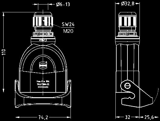
21 Han-Eco Size 10 A Cable entry Identification Part number metric Drawing Dimensions in mm Surface mounted housing with integrated cable gland side entry for industrial applications for outdoor applications M20 M25 M20 M25 Surface mounted housing with integrated cable gland side entry with cover for industrial applications for outdoor applications M20 M25 M20 M25 Surface mounted housing with integrated cable gland side entries for industrial applications for outdoor applications Surface mounted housing with integrated cable gland side entries with cover M20 M25 M20 M25 for industrial applications for outdoor applications Cable to cable housing M20 M25 M20 M25 top entry for industrial applications for outdoor applications M20 M25 M20 M25 21


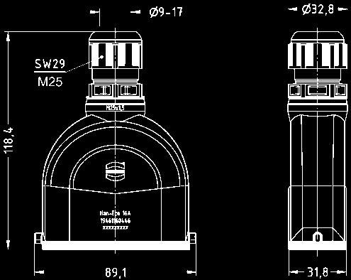
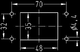
22 Han-Eco Size 16 A Cable entry Identification Part number metric Drawing Dimensions in mm Hood with integrated cable gland side entry for industrial applications for outdoor applications M20 M25 M20 M25 Hood with integrated cable gland top entry for industrial applications for outdoor applications M20 M25 M20 M25 Bulkhead mounted housing for industrial applications for outdoor applications panel cut out for insert assembly from rear side panel cut out Bulkhead mounted housing with cover for industrial applications for outdoor applications panel cut out for insert assembly from rear side panel cut out 22


23 Han-Eco Size 16 A Cable entry Identification Part number metric Drawing Dimensions in mm Surface mounted housing with integrated cable gland side entry for industrial applications for outdoor applications M20 M25 M20 M25 Surface mounted housing with integrated cable gland side entry with cover for industrial applications for outdoor applications M20 M25 M20 M25 Surface mounted housing with integrated cable gland side entries for industrial applications for outdoor applications Surface mounted housing with integrated cable gland side entries with cover for industrial applications for outdoor applications M20 M25 M20 M25 M20 M25 M20 M25 Cable to cable housing top entry for industrial applications for outdoor applications M20 M25 M20 M25 23

24 Han-Modular HMC Features Multi-faceted connector system consisting of modules, contacts, frames, hoods and housings Designed for 10,000 mating cycles Numerous possible combinations of power, data and signal Space saving due to combination of different transmission media in one single connector Technical characteristics Specifications DIN EN DIN EN Approvals Inserts Number of contacts Rated current A Rated voltage V Pollution degree 3 Material Polycarbonate Material outer conductor Zinc alloy HMC Limiting temperatures - 40 C C Flammability acc. to UL 94 V 0 Mechanical working life - mating cycles 10,000 Technical characteristics Contacts Han C HMC Material Copper alloy Surface HMC gold plated Contact resistance 1 mω Crimp terminal - mm² mm² - AWG Contacts Han D HMC Material Copper alloy Surface HMC gold plated Contact resistance 3 mω Crimp terminal - mm² mm² - AWG Contacts Han E HMC Material Copper alloy Surface HMC gold plated Contact resistance 1 mω Crimp terminal - mm² mm² - AWG Contacts D-Sub HMC Material Copper alloy Surface HMC gold plated Contact resistance 10 mω Crimp terminal - mm² mm² - AWG
25 Summary Han-Modular HMC Series Han E module Han EE module Han E Protected module Han EEE module Number of contacts Modules Crimp terminal Crimp terminal Crimp terminal Crimp terminal Rated current Rated voltage Wire gauge 16 A 500 V mm² 16 A 400 V mm² 16 A 830 V mm² 16 A 500 V mm² Male insert (M) Female insert (F) Series Han DD module Han DDD module Han High Density module Number of contacts Modules Crimp terminal Crimp terminal Crimp terminal Rated current Rated voltage Wire gauge 10 A 250 V mm² 10 A 160 V mm² 4 A 50 V mm² Male insert (M) Female insert (F) Series Han 40 A Crimp module Han C module Han CC Protected module Han CD module Number of contacts / 4 Modules Crimp terminal Crimp terminal Crimp terminal Crimp terminal Rated current Rated voltage Wire gauge 40 A 1000 V mm² 40 A 690 V mm² 40 A 830 V mm² 40 A / 10 A 830 V / 830 V mm² / mm² Male insert (M) Female insert (F)
26 Summary Han-Modular HMC Series Han GigaBit HMC module Han MegaBit HMC module Han MegaBit HMC module Han Shielded HMC module Numbers of contacts 8 2 x 4 2 x 4 20 Termination Crimp termination Crimp termination Crimp termination Crimp termination Available August 2015 Wire gauge Ethernet Cat. 6 A ,52 mm² Ethernet Cat. 5e ,5 mm² Ethernet Cat. 5e ,5 mm² mm² Male insert (M) Female insert (F) Series Hinged frame HMC 6 B Hinged frame HMC 10 B Hinged frame HMC 16 B Hinged frame HMC 24 B Number of modules Marking (A...F) Marking (a...f) Series Docking frame 6 B Docking frame 10 B Docking frame 16 B Docking frame 24 B Number of modules Marking (A...F) Marking (a...f)
27 Han-Modular HMC contacts Wire gauge Part number Identification mm² Male contact Female contact Drawing Dimensions in mm Han C HMC Crimp contact HMC gold plated for 40 A Available August mm² 2.5 mm² 4 mm² 6 mm² 10 mm² Wire gauge AWG 16 AWG 14 AWG 12 AWG 10 AWG 8 Ø Stripping length 9.5 mm 9.5 mm 9.5 mm 9.5 mm 15 mm Han E HMC Crimp contact HMC gold plated for 16 A Identification no groove no groove 1 groove* 1 groove 2 groove 3 groove wide groove no groove Operating contact identification Wire gauge mm² 0.5 mm² 0.75 mm² 1 mm² 1.5 mm² 2.5 mm² 3 mm² 4 mm² AWG AWG 20 AWG 18 AWG 18 AWG 16 AWG 14 AWG 12 AWG 12 Stripping length 7.5 mm 7.5 mm 7.5 mm 7.5 mm 7.5 mm 7.5 mm 7.5 mm 7.5 mm * on the rear crimp collar Han D HMC Crimp contact HMC gold plated for 10 A mm² 0.5 mm² 0.75 mm² 1 mm² 1.5 mm² 2.5 mm² Wire gauge AWG AWG 20 AWG 18 AWG 18 AWG 16 AWG 14 Ø Stripping length 8 mm 8 mm 8 mm 8 mm 8 mm 6 mm D-Sub HMC Crimp contact HMC gold plated for data transmission Wire gauge mm² mm² mm² Ø AWG AWG AWG Stripping length 4 mm 4 mm 4 mm Available June
28 Han-Modular Hinged frames HMC Features Pre-leading grounding system according VDE Gold-plated and stable fixated PE contacts ensure mating cycles Mountable in Han B HMC hoods and housings Modules can only be assembled polarized to guarantee a correct orientation Alphabetical marking of module position High mechanical reliability of modules in case of vibration and impact stress No tools necessary to mount and remove modules Technical characteristics Specifications DIN EN DIN EN Approvals Hinged frames Number of modules 2, 3, 4, 6 PE contact Wire gauge - Power side * mm² AWG Signal side mm² AWG Material zinc die-cast Limiting temperatures -40 C C Mechanical working life - mating cycles Hoods/Housings Material aluminium die-cast Surface powder-coated RAL 7037 Locking element Han-Easy Lock HMC Flammability acc. to UL 94 V 0 Hoods/Housings seal NBR Limiting temperatures -40 C C Degree of protection acc. to DIN EN for coupled connector IP65 28 * 10 mm² / AWG 8 only with ferrule crimp tool
")


 09 14 000 9960 09 14 000")
 Hinged frames can")
29 Han-Modular Hinged frames HMC Part number for Hood/Housing 1) Identification Size Marking A... F Marking a... f Drawing Dimensions in mm Hinged frame HMC for 2 modules 6 B Hoods Housings Hinged frame HMC for 3 modules 10 B Hinged frame HMC for 4 modules 16 B Hinged frame HMC for 6 modules 24 B Panel cut out Size A B C 6 B B B B Locking element for hinged frames (20 pieces per bloc) Ideal to pre-assemble the hinged frames 1) Hinged frames can be used either in hood or housing. Both different markings must be used for one connector! 29
30 Han 200 A Protected Crimp module Features Crimp termination Protective insert in the module and protective cap on the male contact ensure IP20 protection Contacts can be unlocked from the mating side Current carrying capacity The current carrying capacity of the connectors is limited by the thermal load capability of the contact element material including the connections and the insulating parts. The derating curve is therefore valid for currents which flow constantly (non-intermittent) through each contact element of the connector evenly, without exceeding the allowed maximum temperature. Measuring and testing techniques according to DIN EN Technical characteristics Specifications DIN EN DIN EN EN Inserts Number of contacts 1 Electrical data acc. to DIN EN Rated current 200 A Rated voltage conductor - ground 1000 V Rated voltage conductor - conductor 1000 V Rated impulse voltage 8 kv Pollution degree 3 Insulation resistance Ω Material Polycarbonate Limiting temperatures -40 C C Degree of protection IP20 Flammability acc. to UL 94 V 0 Mechanical working life 500 mating cycles Contacts Material power contacts Copper alloy Material protective cap Polycarbonate Surface - hard-silver plated 3 µm Ag Contact resistance 0.3 mω Crimp terminal - mm² mm² Max. insulation diameter 18 mm Stripping length 22.5 mm Operating current (A) Ambient temperature ( C) ➀ 24 B hoods/housings with 3 modules; wire gauge: 50 mm² ➁ 24 B hoods/housings with 3 modules; wire gauge: 70 mm² 30
 Female insert (F) Drawing Dimensions")


31 Han 200 A Protected Crimp module 1000 V 200 A Number of contacts 1 Part number Identification Male insert (M) Female insert (F) Drawing Dimensions in mm Crimp termination Module with protective insert M F Removal tool for TC contacts in 200 A crimp module Wire gauge Part number Identification mm² Male contact Female contact Drawing Dimensions in mm Crimp contact silver plated with protective polycarbonate cap Wire gauge Ø Stripping length 25 mm² mm 35 mm² mm 50 mm² mm 70 mm² mm for stranded wires acc. to IEC class 5 31
32 Han USB 3.0 module Features According to USB 3.0 specification Transmission rates up to 5 Gbit/s Simple and cost effective termination by plug in patch cable Technical characteristics Specifications DIN EN DIN EN Inserts Number of contacts 4 Electrical data acc. to EN A 50 V 0.8 kv 3 Rated current 1 A Rated voltage 50 V Rated impulse voltage 0.8 kv Transmission rate 5 Gbit/s Pollution degree 3 Rated voltage acc. to UL < 30 V Insulation resistance Ω Material Polycarbonate Limiting temperatures - 40 C C Flammability acc. to UL 94 V 0 Mechanical working life - mating cycles


33 Han USB 3.0 module 50 V 1 A Number of contacts 4 Part number Identification Male insert (M) Female insert (F) Drawing Dimensions in mm Module for patch cable Male insert Module for patch cable Female insert
34 Han DD Quad Module Features Flexible use in the Han-Modular system Double module for 42 contacts Contact density raised by 25 % Proven Han D crimp contacts Technical characteristics Specifications DIN EN DIN EN Inserts Number of contacts 42 Electrical data acc. to EN A 150 V 2.5 kv 3 Rated current 10 A Rated voltage 150 V Rated impulse voltage 2.5 kv Pollution degree 3 Rated voltage acc. to UL Insulation resistance Material 250 V Ω LCP Limiting temperatures -40 C C Flammability acc. to UL 94 V 0 Mechanical working life - mating cycles 500 Contacts Material Copper alloy Surface - hard-silver plated 3 µm Ag - hard-gold plated 2 µm Au over 3 µm Ag Ni Contact resistance 1 mω Crimp termination - mm² mm² - AWG
 Drawing Dimensions in mm Crimp termination Order crimp contacts separately 09 14 042 3001")


35 Han DD Quad Module 150 V 10 A Number of contacts 42 Part number Identification Male insert (M) Female insert (F) Drawing Dimensions in mm Crimp termination Order crimp contacts separately M F Contact arrangement view from termination side Wire gauge Part number Identification mm² Male contact Female contact Drawing Dimensions in mm Crimp contacts silver plated gold plated Wire gauge Ø Stripping length mm² AWG mm 0.5 mm² AWG mm 0.75 mm² AWG mm 1.0 mm² AWG mm 1.5 mm² AWG mm 2.5 mm² AWG mm 35
36 Han RJ45 Module with prelink and IDC termination Features Compatible with Han RJ45 male module (e.g ) Category of transmission Cat. 6 Field-assembly with HARAX 360 shielding Technical characteristics Number of contacts 8 Transmission Category 6, class E A, suitable for 1/10 Gigabit Ethernet Transmission performance Category 6 / class E A up to 500 MHz acc. to ISO/IEC :2002, EN Transmission rate 10/100 Mbit/s and 1/10 Gbit/s Mounting Cable termination Connectable cables Field-assembly with IDC-contacts, without tools - Conductor cross section AWG 28 AWG 24 AWG 24 AWG 22 - Conductor diameter max. 1.6 mm (incl. insulation) - Cable diameter mm Mating cycles 500 Temperature range -40 C +70 C Housing material Zinc die-cast, nickel-plated 36


37 Han RJ45 Module with prelink and IDC termination Identification Part number Drawing Dimensions in mm Han RJ45 Module, female RJ45 cable jack, order separately Han RJ45 cable jack 8-poles, Cat. 6, prelink termination AWG poles, Cat. 6, IDC termination AWG poles, Cat. 6, IDC termination AWG poles, Cat. 5, IDC termination AWG
38 Han Megabit Module with 1 Cable Entry Features Shielding bus separate from housing potential Suitable for Ethernet Cat. 5e Suitable for Han B, Han M, Han EMC and Han HPR hoods and housings, high construction Technical characteristics Specifications DIN EN DIN EN Han module adapter Number of contacts 2 x 4 Insulation resistance Material Ω polycarbonate Limiting temperatures -40 C C Flammability acc. to UL 94 V 0 Mechanical working life 500 mating cycles Han Megabit insert Number of contacts 2 x 4 + shielding Electrical data acc. to DIN EN A 50 V 0.8 kv 3 Rated current 10 A Rated voltage 50 V Rated impulse voltage 0.8 kv Pollution degree 3 Material - insulator polycarbonate - outer conductor zinc alloy Contact resistance 4 mω Limiting temperatures -40 C C Flammability acc. to UL 94 V 0 Outer surface finish nickel Cable diameter mm Han D crimp contacts Material Copper alloy Surface - hard-silver plated 3 µm Ag - hard-gold plated 3 µm Au over 3 µm Ni Contact resistance 3 mω Crimp terminal - mm² mm² - AWG

 Drawing Dimensions in mm Han module")


39 Han Megabit Module with 1 Cable Entry 50 V 10 A Number of contacts 2 x 4 Part number Identification Male insert (M) Female insert (F) Drawing Dimensions in mm Han module adapter M F Wire gauge Part number Identification mm² Male contact Female contact Drawing Dimensions in mm Megabit insert 2 x 4 contacts order crimp contacts separately x 4 contacts with additional shield connection to the hinged frame order crimp contacts separately Han D Crimp contacts gold plated Wire gauge mm² 0.5 mm² 0.75 mm² 1.0 mm² 1.5 mm² 2.5 mm² AWG AWG 20 AWG 18 AWG 18 AWG 16 AWG 14 ø Stripping length of stranded wire 8 mm 8 mm 8 mm 8 mm 8 mm 6 mm 39
40 Han Megabit Module / Accessories Identification Part number Drawing Dimensions in mm Crimp flange D D D1 D2 Crimp ferrule D D D4 D3 Cable clamp cable diameter approx mm cable diameter approx mm for cable Ø approx mm for cable Ø approx mm 40
41 Han-Yellock Multiplier block Features Suitable for: - Hoods / housings sizes 10 B, 16 B, 24 B, 32 B, 48 B - Hoods / housings for Han-Eco, sizes 6 B, 10 B, 16 B, 24 B - Hoods / housings for Han-Snap, sizes 10 B, 16 B, 24 B - Han-Modular Docking frame and Hinged frame size 10 B, 16 B, 24 B Up to 3 Han-Yellock multipliers can be used in one multiplier block By using the multipliers, the potential of one up to five contacts can be multiplied Suitable only for use with Han E male contacts Technical characteristics Specifications DIN EN DIN EN Inserts Number of contacts 15 Electrical data acc. to EN A 500 V 6 kv 3 Rated current 16 A Rated voltage 500 V Rated impulse voltage 6 kv Pollution degree 3 Electrical data, pollution degree 2 16 A 690 V 8 kv 2 Insulation resistance Ω Material Polycarbonate Limiting temperatures -40 C C Flammability acc. to UL 94 V 0 Mechanical working life - mating cycles 500 Contacts Material Copper alloy Surface - hard-silver plated 3 µm Ag Contact resistance 1 mω Crimp terminal - mm² mm² - AWG
 Female insert (F) Drawing Dimensions in mm Han-Yellock Multiplier block 09 14 015 3001 09 14 015")


42 Han-Yellock Multiplier block 500 V 16 A Number of contacts 1 15 Part number Identification Male insert (M) Female insert (F) Drawing Dimensions in mm Han-Yellock Multiplier block M F Wire gauge Part number Identification mm² male contact Drawing Dimensions in mm Crimp termination Power contacts silver plated Identification Wire gauge no groove mm² AWG no groove 0.5 mm² AWG 20 1 groove* 0.75 mm² AWG 18 1 groove 1 mm² AWG 18 2 grooves 1.5 mm² AWG 16 3 grooves 2.5 mm² AWG 14 wide groove 3 mm² AWG 12 no groove 4 mm² AWG 12 Stripping length 7.5 mm 7.5 mm 7.5 mm 7.5 mm 7.5 mm 7.5 mm 7.5 mm 7.5 mm * on the rear crimp collar 42
43 Han-Yellock Multiplier Number of contacts 5 Identification Part number Drawing Dimensions in mm Han-Yellock Multiplier Multiplier 1: Multiplier 2: Multiplier 3: Multiplier 4: Multiplier 5: Multiplier 5: Multiplier 2;3:

44 Han Ex Available May 2015 Connectors for explosion hazardous environments Features Hoods and housings in the sizes 6 B, 10 B, 16 B and 24 B Connectors especially for explosion hazardous applications Suitable for intrinsically safe circuits Inserts on the basis of Han E with 6 to 24 contacts Industrial connectors of the Han Ex WARNING series are designed exclusively for the use in intrinsically safe electrical circuits of categories ia, ib and ic! The explosion group is defined by the corresponding intrinsically safe equipment. Temperature class according to DIN EN General description The connectors are designed to meet the intrinsic safety requirements for ignition protection class in explosion hazardous areas classed as 1 and 2. In intrinsically safe circuits, energy is limited in such a manner that even a potential spark cannot ignite an explosive environment. The Han Ex product portfolio offers complete connector systems consisting of housings and inserts, including housings made from an alloy that can be used in pulverised methane-coal dust atmospheres. They also offer ignition protection class 65 in the mated condition. The housing s blue colour indicates that an intrinsically safe circuit is present. The contact inserts provide a high number of pins and meet the standards of the ignition protection class even in the tightest of spaces. Technical characteristics Specifications DIN EN , -11, -14 DIN EN DIN EN Hoods/ housings Material Colour Surface Locking element Lever type Seal zinc die cast RAL 5015 (blue) powder coated stainless steel metal lever NBR Limiting temperatures -20 C C Protection degree acc. to DIN EN in locked position IP65 is achieved with cable gland Inserts Number of contacts 6, 10, 16, 24 Rated current 16 A Rated voltage 90 V Insulation resistance Ω Material polycarbonate Limiting temperatures -20 C C Mechan. working life - mating cycles 500 Contacts Material copper alloy Surface - hard-silver plated 3 µm Ag Contact resistance 1 mω Crimp termination mm² AWG Max. insulation diameter 3.6 mm 44


45 Han Ex Hoods and Housings Sizes 6 B, 10 B, 16 B, 24 B Cable Identification Part number entry Drawing Dimensions in mm Hood 6 B top entry M20 Hood 10 B top entry M25 Hood 16 B top entry M25 Hood 24 B top entry M32 45


46 Han Ex Hoods and Housings Sizes 6 B, 10 B, 16 B, 24 B Identification Part number Drawing Dimensions in mm Housing, bulkhead mounting 6 B Panel cut out Housing, bulkhead mounting 10 B Panel cut out Housing, bulkhead mounting 16 B Housing, bulkhead mounting 24 B Panel cut out 46 Panel cut out
47 Han Ex Inserts Sizes 6 B, 10 B, 16 B, 24 B Number of contacts 6, 10, 16, 24 + Part number Identification Male insert (M) Female insert (F) Drawing Dimensions in mm Han Ex crimp insert 6 B 2)3) Order crimp contacts separately M F Han Ex crimp insert 10 B 2)3) Order crimp contacts separately ) Distance for contact max. 21 mm Size a b c d e f 6 B B B B Contact arrangement view from termination side 6 B Han Ex crimp insert 16 B 2)3) Order crimp contacts separately B 16 B Han Ex crimp insert 24 B 2)3) Order crimp contacts separately B 2) Han E crimp contacts can be ordered in the HARTING ecatalogue ( 3) Further inserts on request 47

48 Han B Snap Cap Available September 2015 Han standard metal hoods and housings for industrial applications Features Compatible with all standard hoods and housings Proven locking system Han-Easy Lock Automatic closing mechanism Protection degree IP66 und IP67 Protective collar keeps the seal in place Technical characteristics Hoods / housings Material Colour Surface Locking element aluminium die cast RAL 7037 (blue) powder coated stainless steel Lever type Han-Easy Lock Seal NBR Limiting temperatures -40 C C Protection degree acc. to DIN EN in locked position IP66 / IP67 Protection degree acc. to DIN EN in unlocked position IP44 48


49 Han B Snap Cap Identification Part number Drawing Dimensions in mm Housing, bulkhead mounting 6 B with self-closing cap Panel cut out Housing, bulkhead mounting 10 B with self-closing cap Panel cut out Housing, bulkhead mounting 16 B with self-closing cap Panel cut out Housing, bulkhead mounting 24 B with self-closing cap Panel cut out 49
 Powder-coated RAL 9005 (black) NBR")

50 Han 3 A Angled Bulkhead Mounted Housing Features Fixing with 4 screws for maximum security Large cabling space Excellent electro magnetic compatibility Square mounting flange Technical characteristics Material Surface standard version Surface Han M Seal Zinc die-cast Powder-coated RAL 7037 (grey) Powder-coated RAL 9005 (black) NBR Limiting temperatures -40 C C Degree of protection acc. to EN in locked position IP44 IP65/67 with use of sealing screw Identification Part number Drawing Dimensions in mm Angled bulkhead mounted housing Han 3 A Standard Hood Panel cut out Angled bulkhead mounted housing Han 3 M
51 Han 3 A Hood Features With M25 cable entry for big cable diameters Compatible with inserts size Han 3 A Available in standard, Han EMC and Han M Technical characteristics Material Surface standard version Surface Han EMC version Zinc die-cast Powder-coated RAL 7037 (grey) non coated electrically conductive Surface Han M version Powder-coated RAL 9005 (black) Limiting temperatures -40 C C Degree of protection acc. to EN in locked position Cable entry IP44 IP65 / IP67 with use of sealing screw M25 Cable entry Identification Part number metric Drawing Dimensions in mm Hood Han 3 A Standard Hood M25 Hood Han 3 M M25 Hood Han 3 EMC M25 51

52 Han M Plus Hoods and housings for extreme environmental requirements Features Aluminium die-cast hoods and housings with a robust polyurethane surface Ideal for applications with extreme mechanical and chemical influences Durable protection against damage caused by stone chip, icing, salt mist, UV radiation and harsh gases Optimised system use for transportation, maritime applications and petrochemical industry Efficient alternative to complex specific solutions 1) Important note: Han M Plus hoods and housings must be used with metal cable glands only. The length of the thread of the cable gland must be 7 mm minimum. Technical characteristics Hoods and housings Material aluminium die-cast PUR (polyurethane) RAL 9005 (black) PUR (polyurethane) Han-Easy Lock / metal lever PUR (polyurethane) Colour Surface Locking element Hoods / housings seal Limiting temperatures -40 C C Degree of protection acc. to DIN EN for coupled connector IP66 Flammability - acc. to UL 94 in preparation - EN :2013 HL2 / R22 (inside) HL2 / R23 (outside) Tightening torque - M4 fixing screw min. 1 Nm - Metal cable gland 1) M20 10 Nm M25 12 Nm M32 15 Nm M40 15 Nm Chemical resistance acc. to DIN EN Ozone resistance acc. to DIN EN hydraulic oil, cooling lubricant, diesel fuel, detergent for transportation vehicles, antifreezing agent tested on locked connector Mechanical resistance - Stone chipping test DIN ISO Dust and sandblasting test DIN EN Vibration test acc. to DIN EN Hz... 9 Hz: 15 mm 9 Hz Hz: 5g - Shock test acc. to DIN EN g, 18 ms 3 axis - Noise acc. to DIN EN Cat. 2 - UV resistance tested on locked acc. to DIN EN connector 52


 Han M Plus")

53 Han M Plus Kabelausgang Bezeichnung Baugröße Bestellnummer metrisch Maßzeichnung Maße in mm Tüllengehäuse 1) mit seitlichem Kabeleingang und einem Verriegelungsbügel M20 M25 Unterlegscheibe zum Abdichten des Kabelausgangs ist dem Lieferumfang lose beigefügt. Bestellnummer M x 1, x 1,5 Tüllengehäuse 1) mit seitlichem Kabeleingang und zwei Verriegelungsbügeln Han-Easy Lock M25 M32 M32 M40 Unterlegscheibe zum Abdichten des Kabelausgangs ist dem Lieferumfang lose beigefügt M32 M40 Bestellnummer M a b x 1,5 26, x 1,5 26, x 1,5 47,5 96, x 1,5 47,5 96, x 1, x 1, Tüllengehäuse 1) mit geradem Kabeleingang und einem Verriegelungsbügel M20 M25 Unterlegscheibe zum Abdichten des Kabelausgangs ist dem Lieferumfang lose beigefügt. Bestellnummer M x 1, x 1,5 Tüllengehäuse 1) mit geradem Kabeleingang und zwei Verriegelungsbügeln Han-Easy Lock M25 M32 M32 M40 M32 M40 1) Han M Plus Gehäuse dürfen nur mit Metall-Kabelverschraubungen verwendet werden. Die Gewindelänge der Metall-Kabelverschraubung muss min. 7 mm betragen. Bestellnummer M a b x 1,5 26, x 1,5 26, x 1,5 47,5 96, x 1,5 47,5 96, x 1, x 1, Unterlegscheibe zum Abdichten des Kabelausgangs ist dem Lieferumfang lose beigefügt. 53

 Vier O-Ringe zum Abdichten der")


 Vier O-Ringe zum Abdichten")
54 Han M Plus Kabelausgang Bezeichnung Baugröße Bestellnummer metrisch Maßzeichnung Maße in mm Anbaugehäuse 1) mit einem Verriegelungsbügel _ 1) Vier O-Ringe zum Abdichten der Befestigungs- Schraubköpfe sind dem Lieferumfang lose beigefügt. Anbaugehäuse 1) mit zwei Verriegelungsbügeln Han-Easy Lock _ Bestellnummer a b c , , ,2 Montageausschnitt Montageausschnitt 54 1) Vier O-Ringe zum Abdichten der Befestigungs- Schraubköpfe sind dem Lieferumfang lose beigefügt.
 Manual adjustments to different insulation thicknesses are not needed")
55 HARTING Stripping Tool Description Part number Dimensions in mm HARTING Self-adjusting stripping tool for cable cross sections from 0.03 mm² up to 10.0 mm² x 125 mm Features Technical characteristics Designed for cable cross sections up to 10 mm 2 (AWG 8) Manual adjustments to different insulation thicknesses are not needed anymore due to the fully automatic adjustment mechanism Easily adjustable stripping length from 2 mm to 20 mm Integrated cable cutter for single-wire cables and stranded cables Soft rubber grip for safer handling and improved ergonomics Interchangeable cutting mechanism Cable cross sections (stripping): mm 2 (AWG AWG 8) Maximum cable cross sections (cutting): - single-wire cables: 6 mm 2 (AWG 10) - stranded cables: 10 mm 2 (AWG 8) Length: 193 mm Weight: approx. 200 g 55
56 Han 64 EEE panel feed-through Features Panel feed-through for using with Han 64 EEE grip panel solution Fire resistancy acc. to EN : E15 Technical characteristics Number of contacts Rated current Rated voltage Rated impulse voltage Pollution degree 3 Material insert 64 + PE 16 A 500 V 6 KV PC Limiting temperatures -40 C C Degree of protection acc. to DIN EN IP5x Flammability acc. to EN


57 Han 64 EEE panel feed-through Identification Part number Drawing Dimensions in mm Han EEE panel feed-through Cover for Han 64 EEE panel feed-through Part number Identification Male (M) Female (F) Drawing Dimensions in mm Guiding male for Han 64 EEE panel feed-through Guiding system for Han 64 EEE panel feed-through Guiding female for Han 64 EEE panel feed-through
58 Power cable assembly acc. to UL 2237 for Han 6 HsB Description Han Power cable assemblies with UL 2237 listing are intended for the usage on industrial control panel applications according to UL 508 (A, C). Assembled on both sides with the well-proven HARTING male and/or female inserts with crimp or screw terminals for the following product ranges: Han 6 HsB Han 6 E Han 10 E Han 16 E Han 24 E Han Q 4/2 Han Q 8/0 Metal hoods, standard Han B and/or Han-Compact according to UL50/50E with either top or side entry and one or two levers locking system. See catalogue Industrial Connectors Han, chapter 31, for technical characteristics. Technical characteristics Approvals Power cable assembly Number of contacts Electrical data acc. to UL 2237 Maximum current USL/CNL Maximum voltage AC/DC Short-circuit fault value AC/DC Required fuse protection Cable type Number of wires PE 22 A / 15 A 600 V / 300 V 65 ka / 51 ka time delay RK5, CC, J or T class fuses TC-ER Wire gauge AWG 12 Wiring 1:1 Hood size Han 16 B Cables are UL listed type TC-ER. Number of wires and wire gauge are matched to the particular insert. A cable length of 1.0 m and 2.0 m is available. Cable glands are according to UL 514B. Scope of delivery Power cable assembly consisting of: 2 x hoods 1 x male insert with male contacts 1 x female insert with female contacts 2 x cable glands 1 x TC-ER cable 58


59 Power cable assembly acc. to UL 2237 for Han 6 HsB Size 16 B Number of contacts 6 + Available June 2015 Han Power cable assemblies with UL 2237 listing Identification Part number Drawing Dimensions in mm Han 6 HsB Power cable assembly with Han 6 HsB inserts Hoods metal top entry, 2 lever locking system available length: L = 1.0 m L = 2.0 m Hoods metal side entry, 2 lever locking system available length: L = 1.0 m L = 2.0 m
60 Power cable assembly acc. to UL 2237 for Han E Description Han Power cable assemblies with UL 2237 listing are intended for the usage on industrial control panel applications according to UL 508 (A, C). Assembled on both sides with the well-proven HARTING male and/or female inserts with crimp or screw terminals for the following product ranges: Han 6 HsB Han 6 E Han 10 E Han 16 E Han 24 E Han Q 4/2 Han Q 8/0 Metal hoods, standard Han B and/or Han- Compact according to UL50/50E with either top or side entry and one or two levers locking system. See catalogue Industrial Connectors Han, chapter 31, for technical characteristics. Cables are UL listed type TC-ER. Number of wires and wire gauge are matched to the particular insert. A cable length of 1.0 m and 2.0 m is available. Cable glands are according to UL 514B. Technical characteristics Approvals Power cable assembly Number of contacts 6 + PE (Han 6 E) 10 + PE (Han 10 E) 16 + PE (Han 16 E) 24 + PE (Han 24 E) Electrical data acc. to UL 2237 Maximum current 9 A (Han 6 E) 7 A (Han 10 E, Han 16E) 6.5 A (Han 24 E) Maximum voltage AC 600 V Short-circuit fault value AC 65 ka Required fuse protection time delay CC, J or T class fuses Cable type TC-ER Number of wires 7 (Han 6 E) 11 (Han 10 E) 17 (Han 16 E) 25 (Han 24 E) Wire gauge AWG 16 Wiring 1:1 Hood size Han 6 B (Han 6 E) Han 10 B (Han 10 E) Han 16 B (Han 16 E) Han 24 B (Han 24 E) Scope of delivery Power cable assembly consisting of: 2 x hoods 1 x male insert with male contacts 1 x female insert with female contacts 2 x cable glands 1 x TC-ER cable 60


61 Power cable assembly acc. to UL 2237 for Han E Size 16, 10, 16, 24 B Number of contacts Available June 2015 Han Power cable assemblies with UL 2237 listing Identification Part number Drawing Dimensions in mm Han 6 E, Han 10 E, Han 16 E, Han 24 E Power cable assembly with Han 6, 10, 16, und 24 E inserts Hoods metal top entry, 2 lever locking system available length: Han 6 E Han 6 E Han 10 E Han 10 E Han 16 E Han 16 E Han 24 E Han 24 E Hoods metal side entry, 2 lever locking system available length: Han 6 E Han 6 E Han 10 E Han 10 E Han 16 E Han 16 E Han 24 E Han 24 E L = 1.0 m L = 2.0 m L = 1.0 m L = 2.0 m L = 1.0 m L = 2.0 m L = 1.0 m L = 2.0 m L = 1.0 m L = 2.0 m L = 1.0 m L = 2.0 m L = 1.0 m L = 2.0 m L = 1.0 m L = 2.0 m
62 Power cable assembly acc. to UL 2237 for Han Q 4/2 Description Han Power cable assemblies with UL 2237 listing are intended for the usage on industrial control panel applications according to UL 508 (A, C). Assembled on both sides with the well-proven HARTING male and/or female inserts with crimp or screw terminals for the following product ranges: Han 6 HsB Han 6 E Han 10 E Han 16 E Han 24 E Han Q 4/2 Han Q 8/0 Metal hoods, standard Han B and/or Han-Compact according to UL50/50E with either top or side entry and one or two levers locking system. See catalogue Industrial Connectors Han, chapter 13, for technical characteristics. Technical characteristics Approvals Power cable assembly Number of contacts 4/2 + PE Power contacts 4 Signal contacts 2 Electrical data acc. to UL 2237 Maximum current Maximum voltage AC Short-circuit fault value AC Required fuse protection Cable type Number of wires 7 20 A 480 V 5 ka Wire gauge AWG 12 Wiring 1:1 time delay RK5, J or CC class fuses TC-ER (SOOW listed) Hood size Han-Compact Cables are UL listed type TC-ER. Number of wires and wire gauge are matched to the particular insert. A cable length of 1.0 m and 2.0 m is available. Cable glands are according to UL 514B. Scope of delivery Power cable assembly consisting of: 2 x hoods 1 x male insert with male contacts 1 x female insert with female contacts 2 x cable glands 1 x TC-ER cable 62


63 Power cable assembly acc. to UL 2237 for Han Q 4/2 Han-Compact Number of contacts 4/2 + Available June 2015 Han Power cable assemblies with UL 2237 listing Identification Part number Drawing Dimensions in mm Han Q 4/2 Power cable assembly with Han Q 4/2 inserts Hoods metal top entry, 1 lever locking system available length L = 1.0 m L = 2.0 m Hoods metal side entry, 1 lever locking system available length L = 1.0 m L = 2.0 m M F 63
64 Power cable assembly acc. to UL 2237 for Han Q 8/0 Description Han Power cable assemblies with UL 2237 listing are intended for the usage on industrial control panel applications according to UL 508 (A, C). Assembled on both sides with the well-proven HARTING male and/or female inserts with crimp or screw terminals for the following product ranges: Han 6 HsB Han 6 E Han 10 E Han 16 E Han 24 E Han Q 4/2 Han Q 8/0 Metal hoods, standard Han B and/or Han-Compact according to UL50/50E with either top or side entry and one or two levers locking system. See catalogue Industrial Connectors Han, chapter 13 for technical characteristics. Technical characteristics Approvals Power cable assembly Number of contacts 8/0 + PE Power contacts 8 Signal contacts 0 Electrical data acc. to UL 2237 Maximum current Maximum voltage AC / DC Short-circuit fault value AC / DC Required fuse protection Cable type Number of wires 9 12 A 600 V / 300 V 65 ka / 51 ka time delay, CC, J or T class fuses max. 15 A TC-ER Wire gauge AWG 14 Wiring 1:1 Hood size Han-Compact Cables are UL listed type TC-ER. Number of wires and wire gauge are matched to the particular insert. A cable length of 1.0 m and 2.0 m is available. Cable glands are according to UL 514B. Scope of delivery Power cable assembly consisting of: 2 x hoods 1 x male insert with male contacts 1 x female insert with female contacts 2 x cable glands 1 x TC-ER cable 64

65 Power cable assembly acc. to UL 2237 for Han Q 8/0 Han-Compact Number of contacts 8 + Available June 2015 Han Power cable assemblies with UL 2237 listing Identification Part number Drawing Dimensions in mm Han Q 8/0 Power cable assembly with Han Q 8/0 inserts Hoods metal top entry, 1 lever locking system available length: L = 1.0 m L = 2.0 m Hoods metal side entry, 1 lever locking system available length: L = 1.0 m L = 2.0 m M F 65
66 HARTING Hall effect current sensor HCS 200 A small Features Hall effect compensated current sensor Galvanic insulation between primary and secondary current Panel mounting Housing material and potting mass have a flammability rating UL94 V0 Standard EN : Electronic equipment for use in power installations Advantages High accuracy Wide measuring range High current overload capability Very low susceptance to external magnetic fields Technical characteristics I PN Nominal primary current 200 A I P Measuring range 0... ±420 A R M Burden resistance with ±12 V at ±200 A max R M min 0 R M max 69 Ω at ±420 A max R M min 0 R M max 12 Ω with ±15 V at ±200 A max R M min 23 R M max 98 Ω at ±420 A max R M min 23 R M max 26 Ω I SN Nominal secondary current 100 ma K N Turns ratio 1 : 2000 V C Nominal power supply (±5 %) ± V I C Supply VC = 15 V 17+ I S ma X Overall accuracy at I PN T A = +25 C ±0.5 % Ε L Linearity < 0.1 % I O Offset current at I P = 0, T = +25 C max ±0.2 ma I OT Zero offset/temperatur, I O, -40 C C max ±0.4 ma t r Delay time of I PN < 1 μs Di/dt di/dt correctly following > 100 A/μs f Bandwidth DC khz T A Operating temperature range -40 C C T S Storage temperature range -45 C C RS Coil resistance at T A = +85 C 33 Ω V D Proof stress voltage, effective, 50 Hz, 1 minute 3 kv V st Rated impulse voltage 1.2/50 µs 10 kv V B Rated voltage 1) 600 V Approval 66 1) Safe separation (Overvoltage category III, Pollution degree 2)

 recommended fastening torque 3.2 Nm Tolerances ±0.")
67 HARTING Hall effect current sensor HCS 200 A small I PN = 200 A Measureable currents are AC, DC, pulsed Identification Part number Drawing Dimensions in mm HCS 200 A small Sensor fastening: 4 x M4 Steel screws (vertikal) recommended fastening torque 3.2 Nm x M4 Steel screws (horizontal) recommended fastening torque 3.2 Nm Tolerances ±0.5 mm Connections: Spring clamp terminal, pluggable Centerline 2.5 mm; 3 pins
68 HARTING Hall effect current sensor HCS 300 A small Features Hall effect compensated current sensor Galvanic insulation between primary and secondary current Panel mounting Housing material and potting mass have a flammability rating UL94 V0 Standard EN : Electronic equipment for use in power installations Advantages High accuracy Wide measuring range High current overload capability Very low susceptance to external magnetic fields Technical characteristics I PN Nominal primary current 300 A I P Measuring range 0... ±500 A R M Burden resistance with ±12 V at ±300 A max R M min 0 R M max 37 Ω at ±500 A max R M min 0 R M max 8 Ω with ±15 V at ±300 A max R M min 5 R M max 56 Ω at ±500 A max R M min 5 R M max 19 Ω I SN Nominal secondary current 150 ma K N Turns ratio 1 : 2000 V C Nominal power supply (±5 %) ± V I C Supply VC = 15 V 16+ I S ma X Overall accuracy at I PN T A = +25 C ±0.47 % Ε L Linearity < 0.1 % I O Offset current at I P = 0, T = +25 C max ±0.2 ma I OT Zero offset/temperatur, I O, -40 C C max ±0.7 ma t r Delay time of I PN < 1 μs Di/dt di/dt correctly following > 100 A/μs f Bandwidth DC khz T A Operating temperature range -40 C C T S Storage temperature range -45 C C RS Coil resistance at T A = +85 C 30 Ω V D Proof stress voltage, effective, 50 Hz, 1 minute 3 kv V st Rated impulse voltage 1.2/50 µs 10 kv V B Rated voltage 1) 600 V Approval 68 1) Safe separation (Overvoltage category III, Pollution degree 2)
 recommended fastening torque 3.2 Nm 20 31 030 0301 2 x M4 Steel screws (horizontal) recommended fastening torque 3.2 Nm Tolerances ±0.")
69 HARTING Hall effect current sensor HCS 300 A small I PN = 300 A Measureable currents are AC, DC, pulsed Identification Part number Drawing Dimensions in mm HCS 300 A small Sensor fastening: 4 x M4 Steel screws (vertikal) recommended fastening torque 3.2 Nm x M4 Steel screws (horizontal) recommended fastening torque 3.2 Nm Tolerances ±0.5 mm Connections: Spring clamp terminal, pluggable Centerline 2.5 mm; 3 pins
70 Han-Fast Lock Features Solder free PCB termination PCB contact with locking element Stamped contact element Automatic crimping process compatible For use with different Han connectors Cost-effective Easy handling Fast assembly to PCB Contacts with pin - Locking directly on the PCB Contacts without pin - Fast positioning with plastic adapter Technical characteristics Contacts Material Copper alloy Surface - Hard-silver plated 3 µm Ag Contact resistance < 2 mω Direction Straight or angled Locking Material Surface finish Current 10 mm² stranded wire Voltage Board density Copper alloy Passivation 60 A Clearance and creepage distances have to be considered t = mm Description The new connection of wires to the PCB offers optimized PCB design, combined with outstanding contact qualities. The Han-Fast Lock is flexible and allows a fast and simple PCB connection. The PCB has one drilled hole and a pad. The inner surface of the plated drilled hole serves as the interface. The Han-Fast Lock is simply inserted into the plated through contact hole. The locking pin is pushed in and hence locks the contact into position. The solder free connection technique is easy to handle and to operate. Maintenance has been made simple with the facility to detach the contact. Han-Fast Lock also supports SMD assembly of the PCB. Current up to 60 Amps Standard drilled hole with pad Position independent of connector Solder free PCB termination Easy locking solution Straight and angled version Current carrying capacity The current carrying capacity of the connectors is limited by the thermal load capability of the contact element material including the connections and the insulating parts. The derating curve is therefore valid for currents which flow constantly (non-intermittent) through each contact element of the connector evenly, without exceeding the allowed maximum temperature. Measuring and testing techniques according to DIN EN Operating current (A) Ambient temperature ( C) ➀ Wire gauge: 1.5 mm² ➁ Wire gauge: 2.5 mm² ➂ Wire gauge: 4 mm² ➃ Wire gauge: 6 mm² ➄ Wire gauge: 10 mm² 70


71 Han-Fast Lock Identification Part number Drawing Dimensions in mm Contacts with pin on a reel 2300 piece 1.5 to 2.5 mm² Contacts without pin on a reel 2300 piece 1.5 to 2.5 mm² Further plated surfaces on request Single contacts with pin 1.5 to 2.5 mm² Single contacts with pin 1.5 to 2.5 mm² Further plated surfaces on request Single contacts with pin angled 1.5 to 2,5 mm² 4.0 to 6.0 mm² 10.0 mm² Further plated surfaces on request 71
72 Han-Fast Lock Technical characteristics Components Contacts Material Surface Resistance Stripping length mm² Stripping length 4-6 mm² Stripping length 10 mm² Copper alloy Hard silver plated, 3 µm Ag < 2 mω 7.5 mm 7.5 mm 7.5 mm Locking Material Copper alloy Surface Surface passivation Current 10 mm² wire 60 A Voltage Please consider clearance and creepage distances when ordering the printed cicuit board Recommended termination cycles 10 x Limiting temperatures -40 C C PCB PCB thickness Construction PCB Recommended configuration of plated through holes acc. to DIN EN for PCBs Diameter plated through hole t = mm Depending on the required current carrying capacity 1.6 mm d = 4.4 mm mm / mm Chem. Sn PCB Plated through hole Ø 4.4 mm Cu min. 25 µm Sn min. 0.7 µm Cu e.g. Sn plated through hole Ø Au/Ni PCB Plated through hole Ø 4.4 mm Cu min. 25 µm Ni min. 3 µm Au min µm Ag PCB Plated through hole Ø 4.4 mm Cu min. 25 µm Ag min. 0.1 µm Vibration Vibration test DIN EN Hz 0.35 mm, 50 ms² 2 h per axis Shock DIN EN Category 1b 5g 30 ms, 3 shocks per axis Random vibration DIN EN Category 1b ASD-level (m/s²)²/hz (a eff : 7.9m/s²) Test criteria No disconnection >1 µs 72
73 Notes 73
74 Ha-VIS FTS 3000-PTP Introduction and features General description Features Ethernet Switches of the product family Ha-VIS FTS 3000 PTP enable the customer to realise networks with a high demand for time synchronisation. The switches support Rapid Spanning Tree Protocol (RSTP) as well as Media Redundancy Protocol (MRP) and can be installed in different topologies according to the relevant application. Thus increasing the availability of the whole installation. The switches identify automation protocols (e.g PROFINET, EtherNet/IP, Modbus TCP and customised profiles), accelerate the data transmission and prioritise those data packages. They are the suitable PROFINET device for industrial applications and support Ethernet (10 Mbit/s) and Fast Ethernet (100 Mbit/s). The product family enables the connection of up to 10 network devices via Twisted Pair ports or FO interfaces, according to switch type. The Ethernet Switch works as a managed switch in Fast Track Switching mode as well as in Store and Forward mode. It supports Auto-crossing, Autonegotiation and Auto-polarity. Managed Ethernet Switch according to IEEE Identification, acceleration and prioritisation for automation protocols Precision Time Protocol (PTP) according to IEEE 1588v2 in hardware Media Redundancy Protocol (MRP) Master or Slave Deterministic data transfer for selected profiles PROFINET IO Device Robust, slim metal housing SD card slot for storage of the configuration Advantages Cost-efficient implementation of synchronous networks (accuracy of < 100 ns) Space-saving installation in cabinets Avoid production stop caused by traffic overload Easy device exchange High network availability by media redundancy Field of application Industrial automation Automotive industry Machinery & Robotics Energy market Measurement and testing Motion Control 74
 Input voltage / termination 24 V / 5 pin, matable screw contact for redundant power supply Permissible range (min./max.) 9.6 V.")
75 Ha-VIS FTS 3000-PTP Ethernet Switch Ha-VIS FTS 3100-A-PTP 10-Port Ethernet Switch with Fast Track Switching Technology, managed Managed IP30 PROFINET compatible X EtherNet/IP compatible X Number of ports, copper / termination 10 x 10/100Base-TX / RJ45 (Twisted Pair) Input voltage / termination 24 V / 5 pin, matable screw contact for redundant power supply Permissible range (min./max.) 9.6 V V Input current approx. 300 ma (at 24 V DC) Material enclosure anodised aluminium Dimensions (W x H x D) 44 x 130 x 100 mm (without connector) Weight approx. 0.5 kg Working temperature 0 C C Approvals UL 508, UL , DNV Time synchronisation Precision Time Protocol (PTP) hardware based Identification Part number Drawing Dimensions in mm Ha-VIS FTS 3100-A-PTP Ethernet Switch with 10 ports RJ
 2 x 100Base-FX / SFP module slot Input voltage / termination")
 Material enclosure anodised aluminium Dimensions (W x H x D) 44 x 130 x 100 mm (without connector) Weight approx. 0.5 kg Working temperature 0 C.")
76 Ha-VIS FTS 3000-PTP Ethernet Switch Ha-VIS FTS 3082-ASFP-PTP 10-Port Ethernet Switch with Fast Track Switching Technology, with 2 Slots for SFP-Modules, managed Managed IP30 PROFINET compatible X EtherNet/IP compatible X Number of ports, copper / termination Number of ports, FO / termination 8 x 10/100Base-TX / RJ45 (Twisted Pair) 2 x 100Base-FX / SFP module slot Input voltage / termination 24 V / 5 pin, matable screw contact for redundant power supply Permissible range (min./max.) 9.6 V V Input current approx. 300 ma (at 24 V DC) Material enclosure anodised aluminium Dimensions (W x H x D) 44 x 130 x 100 mm (without connector) Weight approx. 0.5 kg Working temperature 0 C C Approvals UL 508, UL Time synchronisation Precision Time Protocol (PTP) hardware based Identification Part number Drawing Dimensions in mm Ha-VIS FTS 3082-ASFP-PTP Ethernet Switch with 8 ports RJ45 2 ports FO
77 Ha-VIS econ/mcon 4100-BB Introduction and Features General description The Ha-VIS 4100-BB Ethernet switches are equipped with 8 Fast Ethernet and 2 Gigabit Ethernet ports and support network infrastructures with high bandwidth requirements. Due to the flat design, these switches can be accommodated in installations where space is restricted towards the cable connection at the front. Mechanical stability and temperature range meet the highest demands. The M12 interface shows its advantage especially in applications at risk of vibrations. Features M12 PushPull interface 2 GigE Uplink ports with By-Pass functionality External Configuration Memory (only for managed variants) 10 ports non blocking switch acc. to IEEE Store and forward switching mode Auto-Crossing, Auto-Negotiation, Auto-Polarity Wide range power supply 24/48 V DC or 72/110 V DC Industrial temperature: -40 C up to +70 C Serial interface (only for managed variants) Digital I/O (1 output / 1 input) optional Advantages Robust metal housing Vibration proof M12 interface for Gigabit and Fast Ethernet Fast and reliable installation with M12 PushPull connectors By-Pass function for maximum reliability External Configuration Memory for storage of the configuration (only managed variants) EMC, temperature range and mechanical stability meet the highest demands All variants are tested acc. to EN Field of application Railway applications Machinery & Robotics Automation technology Wind energy 77
 / M12 D-coding (female) 2 x 10/100/1000Base-T(X) / M12 X-coding (female) Input voltage / termination for redundant power supply M12 A-coding")
 Weight approx. 1 kg Working temperature -40 C.")
78 Ha-VIS econ 4100-BB 10-Port Ethernet Switch with 2 Ports Gigabit Ethernet, unmanaged with M12 PushPull Interface for flat installation Unmanaged IP40 PROFINET compatible X EtherNet/IP compatible X Number of ports, copper / termination 8 x 10/100Base-T(X) / M12 D-coding (female) 2 x 10/100/1000Base-T(X) / M12 X-coding (female) Input voltage / termination for redundant power supply M12 A-coding (male) Variants 24/28 V DC 71/110 V DC Permissible range (min./max.) 12 V V DC 50.4 V V DC Input current see ecatalogue Material enclosure metal Dimensions (W x H x D) 130 x 180 x 54.5 mm (without connectors) Weight approx. 1 kg Working temperature -40 C C Approvals see ecatalogue MTBF see ecatalogue Identification Part number Drawing Dimensions in mm Ha-VIS econ 4100-BB-L 24 V DC, without By-Pass Ha-VIS econ 4100-BB-L-B 24 V DC, with By-Pass Ha-VIS econ 4100-BB-H 110 V DC, without By-Pass Ha-VIS econ 4100-BB-H-B 110 V DC, with By-Pass
 / M12 D-coding (female) 2 x 10/100/1000Base-T(X) / M12 X-coding (female) Input voltage / termination for redundant power supply M12 A-coding (male)")
 Weight ca. 1.1 kg Working temperature -40 C.")
79 Ha-VIS mcon 4100-BB 10-Port Ethernet Switch with 2 Ports Gigabit Ethernet, managed with M12 PushPull Interface for flat installation Managed IP40 PROFINET compatible X EtherNet/IP compatible X Number of ports, copper / termination 8 x 10/100Base-T(X) / M12 D-coding (female) 2 x 10/100/1000Base-T(X) / M12 X-coding (female) Input voltage / termination for redundant power supply M12 A-coding (male) Variants 24/28 V DC 71/110 V DC Permissible range (min./max.) 12 V V DC 50.4 V V DC Input current see ecatalogue Material enclosure metal Dimensions (W x H x D) 130 x 180 x 54.5 mm (without connectors) Weight ca. 1.1 kg Working temperature -40 C C Approvals see ecatalogue MTBF see ecatalogue Management fully managed via Web interface and SNMP Identification Part number Drawing Dimensions in mm Ha-VIS mcon 4100-BB-L 24 V DC, without By-Pass Ha-VIS mcon 4100-BB-L-B 24 V DC, with By-Pass Ha-VIS mcon 4100-BB-H 110 V DC, without By-Pass Ha-VIS mcon 4100-BB-H-B 110 V DC, with By-Pass


80 smart Power Networks Energy Management Available July 2015 Energy Management System Advantages User-defined reports in various formats, with periodic automatic shipping: load profile curve, ABC analysis, Sankey diagram, heat map analysis, etc. Formula-based performance measurement system Monitoring of systems, measurements and metrics; with user-group alarm functionality Wide variety of interfaces: Modbus RTU and TCP, mbus, S0, CSV, SQL, OPC-UA, etc. Every Ha-VIS smartpn-unit has digital outputs which can be switched automatically and manually Complete web-based system including SQL database General description Companies nowadays must monitor and actively manage their energy consumption and associated costs. The smart Power Networks system provides the basis for measuring all relevant energy flows and for optimising the data in a beneficial way. Measuring equipment is interfaced with smart Power Network Units which monitor, convert and forward their data over the Ethernet to centralized software modules. Our integrated network switch can be used to expand your network and to enhance your management capabilities. The web-based software can be configured to fit your requirements. It provides a messaging/alarm system, evaluative functionality, and a reporting function for automatically generating periodic user-defined reports. The live-view function enables you to analyse live measurement values. This system provides the necessary conditions for a DIN EN ISO certification. Identification Part number Drawing Ha-VIS TD 64:1 AS Current transformer with 64:1 A ratio - Additional types available on request Ha-VIS UMG 96 RM 3-phase current meter - Additional types available on request - Ha-VIS smartpn-unit Managed switch with interfaces for recording measurement data Current transformer Current meter smartpn-unit Ha-VIS smartpn-suite smart Power Networks software smartpn-suite 80
81 smart Power Networks Energy Management System description Measuring Collecting data Evaluating Optimising The key to energy management is being able to record all of the company's relevant consumption-based power data. The power usage of your main consumer loads must be measured and analysed for optimisation potential. In addition to the electrical loads which are recorded using these current transformers and meters, you should also be able to measure air consumption, heating energy and cooling capacity. This is why the smart Power Network provides all standard industrial interfaces for connecting any of your existing and other conventional meters. The smartpn-unit collects this measurement data, validates it, and checks that it is within the specified limits. The data is then forwarded via TCP/IP to your database. The data can be saved to the unit itself if your database is unreachable. The smartpn-unit integrates into your existing network infrastructure so that you can use it to capture measurement data wherever you have network connectivity. The integrated switch also permits you to expand your network and connect to network-compliant meters directly. The management functionality (including RSTP, MRP and VLAN) makes it is easy to use in a modern industrial network environment. Data is processed in the central module of the Ha-VIS smartpn software suite and then displayed using the web interface. This is where consistency checks are run, metrics and virtual measuring points are determined, and automatic reports are generated. The following functions are available: Individually customized and configured briefing reports and overviews Line, column and pie charts Sankey diagrams, heat maps and ABC analyses Comparisons of time and measuring points User-defined evaluation rules User groups can be specified for alarm and messaging functions Based on this data and the many evaluative options, you can quickly and easily discover where your power saving potential lies. You can also demonstrate the potential savings that would be generated by any implemented changes. The liveview function enables you to get a detailed analysis of individual measurements: values are displayed directly with minimal delays so that you can analyse routines such as a machine's start-up behaviour. Services HARTING supports you during the planning and implementation of your smart Power Networks energy management system. You can take advantage of our installation, configuration and maintenance service contracts, or use these services on an asneeded basis. 81
82 Ha-VIS RFID IT 86 S (NT) Technical characteristics Frequency range MHz, EU frequency band Protocol EPC Class 1 Gen 2 EPC / User Memory (Chip) 128 Bit / 512 Bit (Monza 4QT) Read range on metal, 2 W ERP, 868 MHz: up to 3 m Temperature range Operational -45 C C Thermal stress test min. temperature -45 C / 1500 h max. temperature +105 C / 1500 h Housing Dimensions (W x D x H) Protection class Mounting Colour 15 x 5 x 3.5 mm IP67 holder with cable tie, glue white/black Measurements Read Range Read Range / m on metal 200 x 200 mm forward Theoretical read range measured in free field conditions (radiated power: 2 W ERP) Frequency (MHz) 82
83 Ha-VIS RFID IT 86 S (NT) Transponder Ha-VIS RFID IT 86 S (NT) Features Optimised for the EU frequency band Very high read ranges, in relation to the housing dimensions Very small size Flexible mounting on different surface shapes Supplied with 3M adhesive pad Holder for mounting option with cable ties included Protection class IP67 Shock resistant General description Ve r y small on-metal transponder, with high read ranges Flexible options to integrate the Ha-VIS RFID IT 86 S (NT) on different metal surfaces Due to the small housing dimensions ideally suited for tool-tagging Optimised for function on metal EPC Class 1 Gen 2 compatible Read range on metal, 2 W ERP, 868 MHz: up to 3 m Identification Part number Drawing Dimensions in mm Ha-VIS RFID IT 86 S (NT) Packaging unit: - 10 pieces - 50 pieces
84 Ha-VIS RFID IT 92 S (NT) Technical characteristics Frequency range MHz, US/Asia frequency band Protocol EPC Class 1 Gen 2 EPC / User Memory (Chip) 128 Bit / 512 Bit (Monza 4QT) Read range on metal, 2 W ERP, 915 MHz: up to 3 m Temperature range Operational -40 C C Thermal stress test min. temperature -40 C / 1500 h max. temperature +85 C / 1500 h Housing Dimensions (W x D x H) Protection class Mounting Colour 15 x 5 x 3.6 mm IP67 holder with cable tie, glue white/black Measurements Read Range Read Range / m on metal 200 x 200 mm forward Theoretical read range measured in free field conditions (radiated power: 2 W ERP) Frequency (MHz) 84

 Packaging unit: - 10")
85 Ha-VIS RFID IT 92 S (NT) Transponder Ha-VIS RFID IT 92 S (NT) Features Optimised for the US/Asia frequency band Very high read ranges, in relation to the housing dimensions Very small size Flexible mounting on different surface shapes Supplied with 3M adhesive pad Holder for mounting option with cable ties included Protection class IP67 Shock resistant General description Ve r y small on-metal transponder, with high read ranges Flexible options to integrate the Ha-VIS RFID IT 92 S (NT) on different metal surfaces Due to the small housing dimensions ideally suited for tool-tagging Optimised for function on metal EPC Class 1 Gen 2 compatible Read range on metal, 2 W ERP, 915 MHz: up to 3 m Identification Part number Drawing Dimensions in mm Ha-VIS RFID IT 92 S (NT) Packaging unit: - 10 pieces - 50 pieces
86 Ha-VIS RFID VT 86 L (HT) Technical characteristics Frequency range MHz, EU frequency band Protocol EPC Class 1 Gen 2 EPC / User Memory (Chip) 160 Bit / 3328 Bit (NXP UCODE I2C) Read range on metal, 2 W ERP, 868 MHz: up to 4 m Temperature range Operational -40 C C Storage -55 C C Housing Dimensions (W x D x H) Protection class Mounting Colour 41 x 11 x 5.15 mm IP67 / IP69K screw, rivet, glue black Measurements Read Range Read Range / m on metal 200 x 200 mm forward Theoretical read range measured in free field conditions (radiated power: 2 W ERP) Frequency (MHz) E-Pattern H-Pattern E-Pattern H-Pattern The general shape of the radiation pattern remains the same, regardless of: Placement of transponder on different metallic surfaces 86

87 Ha-VIS RFID VT 86 L (HT) Available June 2015 Transponder Ha-VIS RFID VT 86 L (HT) Features Optimised for the EU frequency band Very high read ranges, in relation to the housing dimensions Increased memory (User Memory 3.3 kbit) Robust, chemically resistant housing Small size Flexible mounting High temperature resistance Protection class IP69K Integration in type labels possible General description Particularly robust and durable transponder for repair and maintenance applications in extremely harsh environments Optimised for function on metal EPC Class 1 Gen 2 compatible Read range on metal, 2 W ERP, 868 MHz: up to 4 m Identification Part number Drawing Dimensions in mm Ha-VIS RFID VT 86 L (HT) Packaging unit: - 10 pieces - 50 pieces
 Protection class Mounting Colour 41 x 11 x 5.")
88 Ha-VIS RFID VT 92 L (HT) Technical characteristics Frequency range MHz, US/Asia frequency band Protocol EPC Class 1 Gen 2 EPC / User Memory (Chip) 160 Bit / 3328 Bit (NXP UCODE I2C) Read range on metal, 2 W ERP, 915 MHz: up to 4 m Temperature range Operational -40 C C Storage -55 C C Housing Dimensions (W x D x H) Protection class Mounting Colour 41 x 11 x 5.15 mm IP67 / IP69K screw, rivet, glue black Measurements Read Range Read Range / m on metal 200 x 200 mm forward Theoretical read range measured in free field conditions (radiated power: 2 W ERP) Frequency (MHz) E-Pattern H-Pattern E-Pattern H-Pattern The general shape of the radiation pattern remains the same, regardless of: Placement of transponder on different metallic surfaces 88
89 Ha-VIS RFID VT 92 L (HT) Available June 2015 Transponder Ha-VIS RFID VT 92 L (HT) Features Optimised for the US/Asia frequency band Very high read ranges, in relation to the housing dimensions Increased memory (User Memory 3.3 kbit) Robust, chemically resistant housing Small size Flexible mounting High temperature resistance Protection class IP69K Integration in type labels possible General description Particularly robust and durable transponder for repair and maintenance applications in extremely harsh environments Optimised for function on metal Class 1 Gen 2 compatible Read range on metal, 2 W ERP, 915 MHz: up to 4 m Identification Part number Drawing Dimensions in mm Ha-VIS RFID VT 92 L (HT) Packaging unit: - 10 pieces - 50 pieces
90 Ha-VIS RFID VT 89 L (HT) Technical characteristics Frequency range MHz, global use possible Protocol EPC Class 1 Gen 2 EPC / User Memory (Chip) 160 Bit / 3328 Bit (NXP UCODE I2C) Read range on metal, 2 W ERP, 868 MHz: up to 3 m Temperature range Operational -40 C C Storage -55 C C Housing Dimensions (W x D x H) Protection class Mounting Colour 41 x 11 x 5.15 mm IP67 / IP69K screw, rivets, glue black Measurements Read Range Read Range / m on metal 200 x 200 mm forward Theoretical read range measured in free field conditions (radiated power: 2 W ERP) Frequency (MHz) E-Pattern H-Pattern E-Pattern H-Pattern 90 The general shape of the radiation pattern remains the same, regardless of: Placement of transponder on different metallic surfaces 868 MHz or 915 MHz
 Robust, chemically resistant housing Small size Flexible mounting High temperature resistance Protection class IP69K Integration in type labels possible General description")
 Packaging unit: - 10 pieces - 50 pieces 20 92 642 0201 20 92")
91 Ha-VIS RFID VT 89 L (HT) Available June 2015 Transponder Ha-VIS RFID VT 89 L (HT) Features Global use possible thanks to wideband antenna design Increased memory (User Memory 3.3 kbit) Robust, chemically resistant housing Small size Flexible mounting High temperature resistance Protection class IP69K Integration in type labels possible General description Particularly robust and durable transponder for repair and maintenance applications in extremely harsh environments Optimised for function on metal EPC Class 1 Gen 2 compatible Read range on metal, 2 W ERP, 868 MHz: up to 3 m Identification Part number Drawing Dimensions in mm Ha-VIS RFID VT 89 L (HT) Packaging unit: - 10 pieces - 50 pieces
92 Ha-VIS RFID Steel ID 86 S Coin - BSR Technical characteristics Frequency range MHz, EU frequency band Protocol EPC Class 1 Gen 2 EPC / User Memory (Chip) 128 Bit / 512 Bit (Monza 4QT) Temperature range Operational -45 C C Storage -45 C C Housing Dimensions (W x D x H) Protection class Mounting 30 x 6.5 mm IP67 / IP69K screws, rivets, wire Measurements Read range with RFID UHF Handheld (0.5 W ERP) Possibility to read the Coin from both sides Function on metallic surfaces approx. 10 cm yes yes 92


93 Ha-VIS RFID Steel ID 86 S Coin - BSR Available May 2015 Transponder Ha-VIS RFID Steel ID 86 S Coin - BSR Features Optimised for the EU frequency band The steel ID coin is readable from both sides Extremely robust housing Mechanical shock resistance IK10 Flexible mounting with screws, rivets, wire Protection class IP69K Application: - Maintenance of portable equipment General description Particularly robust and durable transponders for repair and maintenance applications in extremely harsh environments, where a high mechanical protection is required. The steel ID coin is optimised to use in industry to improve the maintenance process of portable equipment with an RFID solution. To have a better localisation of the objects (equipped with the steel ID coins) the read range is reduced to 10 cm. EPC Class 1 Gen 2 compatible Identification Part number Drawing Dimensions in mm Ha-VIS RFID Steel ID 86 S Coin - BSR Packaging unit: 10 pieces
94 Ha-VIS RFID Control ETB 86v1 Technical characteristics Frequency range MHz, EU frequency band Protocol EPC Class 1 Gen 2 EPC / User Memory 128 Bit / 512 Bit Read range on metal, 2 W ERP up to 4 m Temperature range Operational -40 C C Housing Dimensions (W x D x H) Protection class Mounting Colour 100 x 60 x 18 mm IP67 screws, rivets, glue black Measurements Read range Read Range / m on metal 200 x 200 mm forward Theoretical read range measured in free field conditions (radiated power: 2 W ERP) Frequency (MHz) Monitoring function Pin assignment of cable Pin colour code function 1 green U V 2 brown input 1 3 white input 2 Status of inputs is stored in the User Memory: decimal address 268 / Bit 0 and 1 (MSB first) Connection example 94


95 Ha-VIS RFID Control ETB 86v1 Available May 2015 Transponder Ha-VIS RFID Control ETB 86v1 Features Passive RFID Transponder with monitoring function Monitoring of 2 inputs Dry contact control via 8 m cable Optimised for the EU frequency band Optimised for function on metal Completely Class 1 Gen 2 compatible Read range on metal, 2 W ERP: up to 4 m Extremely robust and chemically resistant housings Easy fixing (with screws) High temperature resistance Protection class IP67 General description The Ha-VIS RFID Control ETB is an intelligent UHF Transponder acting as a condition monitoring system. In addition to the EPC Header and User Memory, it communicates the status of 2 digital inputs. Due to these inputs i.e. open/closed contacts are connected directly via a cable to the transponder. Passive mode, no power supply on transponder necessary Control transponder for: - industrial conveyor systems - lifts or elevator systems - cable cars - moving parts (machinery) - intelligent vehicles Identification Part number Drawing Dimensions in mm Ha-VIS RFID Control ETB 86v1 Packaging unit: 1 piece
96 Ha-VIS LOCFIELD Technical characteristics General description The Ha-VIS LOCFIELD is a completely new concept. Instead of installing patch antennas, the coax antenna cable itself becomes the antenna. The read range can be varied from a few centimeters to about two metres just by changing the power of the RFID reader. The LOCFIELD antenna can easily be installed in any shape and thus meet the customer s requirements in an extremely flexible way. Applications - Tool identification in machines - Door and window pass-throughs - Wireless sensor networks - Smart shelf - Smart work bench General characteristics Read range from a few cm up to 2 m (strongly depending on reader, configured power and tags) Electric properties Frequency range EU: MHz; FCC: MHz Impedance 50 Ohm VSWR < 1.8:1 Polarisation linear (tags are read in any orientation) Gain approx. -7 dbi Opening angle / read angle 360 Max. power 2 W (applied to antenna) Connection SMA male TNC-rev (on request) Mechanical properties Length see next page Degree of protection IP65 Installation can be mounted directly on any non-conducting surface on conducting surfaces a distance of at least 2 cm is recommended Operating temperature range 20 C C Storage temperature range 40 C C 96
97 Ha-VIS LOCFIELD Ha-VIS LOCFIELD Travelling wave RFID Antenna Identification Part number Ha-VIS LOCFIELD active length: 2 m total length: 2.5 m diameter: 3 mm SMA (m), EU active length: 2 m total length: 2.5 m diameter: 3 mm SMA (m), FCC active length: 2 m total length: 3 m low loss coax cable diameter: 5 mm SMA (m), EU active length: 1 m total length: 1.5 m diameter: 3 mm SMA (m), EU active length: 0.3 m total length: 0.6 m diameter: 3 mm SMA (m), EU active length: 2 m total length: 3 m low loss coax cable diameter: 5 mm SMA (m), FCC active length: 1 m total length: 1.5 m diameter: 3 mm SMA (m), FCC active length: 0.3 m total length: 0.6 m diameter: 3 mm SMA (m), FCC
98 98 Notes


99 Pin shroud Number of contacts 48 Pin shrouds for type F low profile with press-in pins 13 mm I II pcb-thickness Dimension X Identification ± 10 % ± 0.1 Part number Pin shrouds I with locking levers and press-in fixing I without locking levers for screw fixing I with locking levers and press-in fixing I without locking levers for screw fixing II Locking lever for female connector type F 1) Dimensions 1) order 2 pieces per connector Dimensions in mm 99


100 Pin shroud Number of contacts 48 Pin shrouds for type F low profile with press-in pins 13 mm pcb-thickness Dimension X Identification ± 10 % ± 0.1 Part number Pin shrouds suitable for shell housing D20 without locking levers with press-in nuts without locking levers with press-in nuts Dimensions 100 Dimensions in mm


101 Application examples type F Application 1 Female connector Backplane Pin shroud Shell housing D Female connector with crimp contacts Application 2 Female connector Backplane Pin shroud + Locking lever Female connector for crimp contacts


 Board drillings")
")
102 DIN Type H15 Number of contacts 15 Female connectors No. of Identification contacts Part number Drawing Dimensions in mm Female connector low profile with press-in pins 3.6 mm Performance level 1 acc. to IEC ,9 max. 10,1 max. Contact space termination side 5.08 mm f) Board drillings Mounting side 95 max. Contact space termination side 2.54 mm Board drillings Mounting side 102 f) Railway classification NFF , Smoke index: F1, Flammability class: I2

 Individual contacts 1) Female contacts with solder lugs (lockable) 1 09 06 000 6484 09 06 000 6474 2 09 06 000 6481 09 06 000 6471 3 09 06 000 6482 09 06 000 6472 1 09 06 000 7484 09 06")
 Packaging unit 1,000 pieces 3.5 + 0.")
103 DIN Type G Number of contacts max. 64 Female connectors No. of Identification contacts Part number Drawing Dimensions in mm Female connector for crimp contacts Order contacts separately Identification Female crimp FC contacts Identification Wire gauge Part number Performance levels according to IEC Bandoliered contacts (approx. 2,500 pieces) Bandoliered contacts (approx. 250 pieces) Individual contacts 1) Female contacts with solder lugs (lockable) FC 1 FC 2 FC 3 Wire gauge Insulation ø mm² AWG mm Identification Bandoliered contacts 1) Packaging unit 1,000 pieces mm of insulation is stripped from the wires to be crimped For the fabrication in line with the specification please use exclusively crimp tools approved by HARTING (see DIN EN ) Individual contacts 103
104 har-flexicon PCB connectors male with thread flange, vertical/horizontal for reflow soldering pitch 3.50 / 3.81 mm Packaging unit Identification No. of contacts Part number (pieces) PCB connectors male with thread flange, vertical/horizontal Please insert digit for pitch 3.50 mm þ 4 pitch 3.81 mm þ 5 vertical þ 5 horizontal þ Coding keys for samples (1 piece) for a packaging unit
105 har-flexicon PCB connectors male with thread flange, vertical/horizontal for reflow soldering pitch 3.50 / 3.81 mm Drawing Dimensions vertical horizontal Dimensions in mm Pitch 3.50 mm: L = (3.50 mm x poles) mm Pitch 3.81 mm: L = (3.81 mm x poles) mm a = pitch x (poles - 1) Technical characteristics Technical data Rated current Pitch 11 A 3.50 mm / 3.81 mm Surge voltage category / pollution degree III/3 III/2 II/2 Rated voltage 150 V 150 V 300 V Rated surge voltage 2.5 kv 2.5 kv 2.5 kv Pitch 3.50 mm: L = (3.50 mm x poles) mm Pitch 3.81 mm: L = (3.81 mm x poles) mm a = pitch x (poles - 1) Material data Group of insulation material I Type of insulation material PA / PPA Flammability rating per UL 94 V0 Operating temperature -40 C +110 C Contact material copper alloy Contact plating tin plated Solder pin data Solder pin: drilled hole diameter 1.2 mm 105
106 har-flexicon PCB connectors female with screw flange, horizontal with push-in-spring-cage termination pitch 3.50 / 3.81 mm Packaging unit Identification No. of contacts Part number (pieces) PCB connectors female with screw flange, horizontal with push-in-spring-cage termination Please insert digit for pitch 3.50 mm þ 4 pitch 3.81 mm þ Coding keys
 Technical characteristics Technical data Rated current Pitch 11 A 3.50 mm / 3.")
107 har-flexicon PCB connectors female with screw flange, horizontal with push-in-spring-cage termination pitch 3.50 / 3.81 mm Drawing Dimensions Dimensions in mm L = (pitch x poles) mm a = pitch x (poles - 1) Technical characteristics Technical data Rated current Pitch 11 A 3.50 mm / 3.81 mm Surge voltage category / pollution degree III/3 III/2 II/2 Rated voltage 150 V 150 V 300 V Rated surge voltage 2.5 kv 2.5 kv 2.5 kv Material data Group of insulation material I Type of insulation material PA Flammability rating per UL 94 V0 Operating temperature -40 C +110 C Contact material copper alloy Contact plating tin plated Conductor data Connection technology wire push-in-spring-cage termination Conductor size solid / stranded / mm² Conductor size AWG Stripping length 9-10 mm 107
108 har-flexicon PCB connectors male with thread flange, vertical/horizontal for reflow soldering pitch 5.08 mm Packaging unit Identification No. of contacts Part number (pieces) PCB connectors male with thread flange, vertical/horizontal Please insert digit for vertical þ 5 horizontal þ Coding keys for samples (1 piece) for a packaging unit
 a = pitch x (poles - 1) Technical characteristics Technical data Rated current Pitch 15 A 5.")
109 har-flexicon PCB connectors male with thread flange, vertical/horizontal for reflow soldering pitch 5.08 mm Drawing Dimensions vertical horizontal Dimensions in mm L = pitch x (poles + 2) a = pitch x (poles - 1) Technical characteristics Technical data Rated current Pitch 15 A 5.08 mm Surge voltage category / pollution degree III/3 III/2 II/2 Rated voltage 250 V 300 V 600 V Rated surge voltage 4 kv 4 kv 4 kv L = pitch x (poles + 2) a = pitch x (poles - 1) Material data Group of insulation material I Type of insulation material PA / PPA Flammability rating per UL 94 V0 Operating temperature -40 C +110 C Contact material copper alloy Contact plating tin plated Solder pin data Solder pin: drilled hole diameter 1.4 mm 109
110 har-flexicon PCB connectors female with screw flange, horizontal with push-in-spring-cage termination pitch 5.08 mm Packaging unit Identification No. of contacts Part number (pieces) PCB connectors female with screw flange, horizontal with push-in-spring-cage termination Coding keys
 Technical characteristics Technical data Rated current Pitch 12 A 5.")
111 har-flexicon PCB connectors female with screw flange, horizontal with push-in-spring-cage termination pitch 5.08 mm Drawing Dimensions Dimensions in mm L = pitch x poles a = pitch x (poles - 1) Technical characteristics Technical data Rated current Pitch 12 A 5.08 mm Surge voltage category / pollution degree III/3 III/2 II/2 Rated voltage 250 V 300 V 600 V Rated surge voltage 4 kv 4 kv 4 kv Material data Group of insulation material I Type of insulation material PA / PPA Flammability rating per UL 94 V0 Operating temperature -40 C +110 C Contact material copper alloy Contact plating tin plated Conductor data Connection technology wire push-in-spring-cage termination Conductor size solid / stranded / mm² Conductor size AWG Stripping length 10 mm 111
112 har-flexicon PCB terminal blocks, vertical with push-in-spring-cage termination for reflow soldering pitch 5.00 mm Packaging unit Identification No. of contacts Part number (pieces) PCB terminal blocks, stackable, vertical with push-in-spring-cage termination for samples (1 piece) for a packaging unit

113 har-flexicon PCB terminal blocks, vertical with push-in-spring-cage termination for reflow soldering pitch 5.00 mm Drawing Dimensions Dimensions in mm Technical characteristics Technical data Rated current Pitch 12 A 5.00 mm Surge voltage category / pollution degree III/3 III/2 II/2 Rated voltage 300 V 300 V 600 V Rated surge voltage 4 kv 4 kv 4 kv Material data L = pitch x poles a = pitch x (poles - 1) Group of insulation material I Type of insulation material PA / PPA Flammability rating per UL 94 V0 Operating temperature -40 C +110 C Contact material copper alloy Contact plating tin plated Conductor and solder pin data Connection technology wire push-in-spring-cage termination Conductor size solid / stranded / mm² Conductor size AWG Stripping length 10 mm Solder pin: drilled hole diameter 1.4 mm 113
114 har-flexicon PCB terminal blocks, horizontal with screw termination 10 mm² / 25 mm² for reflow soldering pitch / mm Packaging unit Identification No. of contacts Part number (pieces) PCB terminal blocks, stackable horizontal with screw termination For wire gauge 10 mm² Pitch mm 600 V 60 A For wire gauge 25 mm² Pitch mm 600 V 108 A
 60 / 108 A 10.16 / 15.")

115 har-flexicon PCB terminal blocks, horizontal with screw termination 10 mm² / 25 mm² for reflow soldering pitch / mm Drawing Dimensions in mm Dimensions Pitch mm Pitch mm Technical characteristics Technical data Rated current Pitch L = pitch x poles a = pitch x (poles - 1) 60 / 108 A / mm Surge voltage category / pollution degree III/3 III/2 II/2 Rated voltage 1 kv 1 kv 1 kv Rated surge voltage 8 kv 8 kv 8 kv Material data L = pitch x poles a = pitch x (poles - 1) Group of insulation material I Type of insulation material PA / PPA Flammability rating per UL 94 V0 Operating temperature -40 C +110 C Contact material copper alloy Contact plating tin plated Conductor and solder pin data Pitch mm Pitch mm Connection technology wire screw termination screw termination Conductor size solid / stranded / mm² / mm² Conductor size AWG Screw thread M4 M5 Tightening torque Nm Nm Stripping length mm 18 mm Solder pin: drilled hole diameter min. 1.5 mm min. 1.6 mm PCB thickness max. 2.4 mm max. 2.4 mm 115
 and PoE+ (IEEE 802.3at) Technical characteristics Locking PushPull technology acc.")

 Conductor diameter 1.3 1.")
116 HARTING Ethernet cabling Ha-VIS prelink Han PushPull, type acc. to IEC variant 14 prelink RJ45-connector Advantages HARTING PushPull technology 360 shielding Category of transmission Cat. 6 A Suitable for solid and stranded wires Suitable for PoE (IEEE 802.3af) and PoE+ (IEEE 802.3at) Technical characteristics Locking PushPull technology acc. to IEC Degree of protection IP65 / IP67 Mating face RJ45 acc. to IEC Number of contacts 8 Transmission category Category 6 A, Class E A, suitable for 1/10 Gigabit Ethernet Transmission performance Category 6 A / Class E A up to 500 MHz acc. to ISO/IEC :2002, EN Transmission rate 10/100 Mbit/s and 1/10 Gbit/s Shielding fully shielded, 360 shielding contact Mounting IDC termination Cable termination for prelink terminal module, yellow, Connectable cables Conductor cross section AWG 23 AWG 22 (solid and stranded) Conductor diameter mm Cable termination for prelink terminal module, white, Connectable cables Conductor cross section AWG 27 AWG 26 (solid and stranded) Conductor diameter mm Cable diameter mm Mating cycles min. 750 Temperature range -40 C C Housing material Plastic, black Identification Part number Drawing Dimensions in mm Han PushPull prelink RJ45 connector, straight Ha-VIS prelink RJ45 terminal module AWG 22/23, yellow 1) AWG 26/27, white 1) Ha-VIS prelink assembly tool ) Packaging with 10 pieces

 and PoE+ (IEEE 802.")


 Conductor diameter 1.3 1.")
 Conductor diameter 0.8 1.1 mm Cable diameter 6.3 8.8 mm Mating cycles min. 750 Temperature range -40 C.")
117 HARTING Ethernet cabling Ha-VIS prelink Han PushPull, type acc. to IEC variant 14 prelink RJ45-connector, straight and angled Advantages HARTING PushPull technology 45 angled cable entry, bottom side, for space saving cabling 360 shielding Category of transmission Cat. 6 A Suitable for solid and stranded wires Suitable for PoE (IEEE 802.3af) and PoE+ (IEEE 802.3at) Technical characteristics Locking PushPull technology acc. to IEC Degree of protection IP65 / IP67 Mating face RJ45 acc. to IEC Number of contacts 8 Transmission category Category 6 A, Class E A, suitable for 1/10 Gigabit Ethernet Transmission performance Category 6 A / Class E A up to 500 MHz acc. to ISO/IEC :2002, EN Transmission rate 10/100 Mbit/s and 1/10 Gbit/s Shielding fully shielded, 360 shielding contact Mounting IDC termination Cable termination for prelink terminal module, yellow, Connectable cables Conductor cross section AWG 23 AWG 22 (solid and stranded) Conductor diameter mm Cable termination for prelink terminal module, white, Connectable cables Conductor cross section AWG 27 AWG 26 (solid and stranded) Conductor diameter mm Cable diameter mm Mating cycles min. 750 Temperature range -40 C C Housing material Zinc die-cast, nickel-plated Identification Part number Drawing Dimensions in mm Han PushPull prelink RJ45 connector, straight Han PushPull prelink RJ45 connector, angled Ha-VIS prelink RJ45 terminal module AWG 22/23, yellow 1) AWG 26/27, white 1) Ha-VIS prelink assembly tool ) Packaging with 10 pieces 117
 and PoE+ (IEEE 802.3at) Technical characteristics Connector type RJ45 connector acc.")
118 HARTING Ethernet cabling Ha-VIS prelink Ha-VIS prelink RJ45 connector Advantages RJ45 Ethernet-Data connector suitable for industry Compact and robust design 360 shielding Ergonomically unlocking clip Category of transmission Cat. 6 A Suitable for solid and stranded wires Suitable for PoE (IEEE 802.3af) and PoE+ (IEEE 802.3at) Technical characteristics Connector type RJ45 connector acc. to IEC Number of contacts 8 Transmission category Category 6 A, Class E A, suitable for 1/10 Gigabit Ethernet Transmission performance Category 6 A / Class E A up to 500 MHz acc. to ISO/IEC :2002, EN Transmission rate 10/100 Mbit/s and 1/10 Gbit/s Shielding fully shielded, 360 shielding contact Mounting IDC termination Cable termination for prelink terminal module, yellow, Connectable cables Conductor cross section AWG 23 AWG 22 (solid and stranded) Conductor diameter mm Cable termination for prelink terminal module, white, Connectable cables Conductor cross section AWG 27 AWG 26 (solid and stranded) Conductor diameter mm Cable diameter 5 9 mm Degree of protection IP20 Mating cycles min. 750 Temperature range -40 C C Housing material Zinc die-cast, nickel-plated Identification Part number Drawing Dimensions in mm Ha-VIS prelink RJ45 connector Ha-VIS prelink RJ45 terminal module AWG 22/23, yellow 1) AWG 26/27, white 1) Ha-VIS prelink assembly tool Identification Colour Part number 118 Colour clips for colour coding the Ha-VIS prelink connectors 1) Packaging with 10 pieces White Grey Yellow Magenta Red Blue Green Brown
 Compact bulkhead mounting housing 09 45 545")
 and PoE+ (IEEE 802.3at) Technical characteristics Connector type RJ45 connector acc.")
119 HARTING Ethernet cabling Ha-VIS prelink Ha-VIS prelink RJ45 jacks (HIFF) Advantages Compact and robust design Category of transmission Cat. 6 Suitable for solid and stranded wires Compatible with HIFF dimensions for use in: Han 3 A series with HIFF adapter HARTING PushPull (V4) Compact bulkhead mounting housing EasyInstall bulkhead mounting housing Han PushPull (V14) Panel feed-through plastic Panel feed-through metal rectangular Panel feed-through metal circular har-port Suitable for PoE (IEEE 802.3af) and PoE+ (IEEE 802.3at) Technical characteristics Connector type RJ45 connector acc. to IEC Number of contacts 8 Transmission category Category 6 A, Class E A, suitable for 1/10 Gigabit Ethernet Transmission performance Category 6 A / Class E A up to 500 MHz acc. to ISO/IEC :2002, EN Transmission rate 10/100 Mbit/s and 1/10 Gbit/s Shielding fully shielded, 360 shielding contact Mounting IDC termination Cable termination for prelink terminal module, yellow, Connectable cables Conductor cross section AWG 23 AWG 22 (solid and stranded) Conductor diameter mm Cable termination for prelink terminal module, white, Connectable cables Conductor cross section AWG 27 AWG 26 (solid and stranded) Conductor diameter mm Cable diameter 5 9 mm Degree of protection IP20 Mating cycles min. 750 Temperature range -40 C C Housing material Zinc die-cast, nickel-plated Identification Part number Drawing Dimensions in mm Ha-VIS prelink set RJ45 jack consists of: 1x RJ45 module 1x terminal module 1x cable tie AWG 22/23 AWG 26/27 Ha-VIS prelink RJ45 jack module Ha-VIS prelink RJ45 terminal module AWG 22/23, yellow 1) AWG 26/27, white 1) Ha-VIS prelink protection cover Ha-VIS prelink unlocking tool Ha-VIS prelink assembly tool 1) Packaging with 10 pieces

 482.6 mm (19 ) x 44.")
120 HARTING Ethernet cabling Ha-VIS prelink Ha-VIS prelink 19 Patch panel, HIFF Advantages Flexible, suitable for Ha-VIS prelink modules RJ45 jack and HARTING RJ Industrial modules in HIFF size Economical, time-saving installation due to the slidable module carrier, frontward and backward removal Safety, additional strain-relief Fully shielded modules connected by module carrier Earth bolt IP20 installation for distributors and switch cabinets Technical characteristics Number of modules 24 Transmission performance Transmission rate Assembly Dimensions (W x H x D) Degree of protection Category 6 / Class E A up to 500 MHz acc. to ISO/IEC :2002, EN up to 10 Gbit/s in 19 racks acc. to IEC/DIN EN (DIN ) mm (19 ) x 44.5 mm (1 U) x 181 mm IP20 Operating temperature range -40 C +70 C Material module carrier, 2-parts front cover steel sheet stainless steel Identification Part number Drawing Dimensions in mm Ha-VIS prelink 19 patch panel, unloaded Suitable modules: Ha-VIS prelink RJ45 jack, HIFF mixed loading possible Range of delivery:: Screw set M5 24 cable ties 1x earth conductor 6 mm² 120


 Identification Part number Drawing Dimensions in")
121 HARTING Ethernet cabling Ha-VIS prelink Ha-VIS prelink HIFF RJ45 AP Box Advantages Flexible, suitable for on-wall mounting or for top-hat mounting rail (35 mm) Economical, time-saving installation due to the use of pre-assembled data cables with Ha-VIS prelink termination Technical characteristics Number of ports, Copper / Termination Transmission performance Transmission rate Shielding 2 / RJ45 jack HIFF Category 6 / Class E A up to 500 MHz acc. to ISO/IEC :2002, EN up to 10 Gbit/s Fully shielded, 360 shielding contact Robust design, powder-coated steel plate housing Structured cabling for industrial premises Cable diameter Mounting Dimensions (WxHxD) Degree of protection 5 mm... 9 mm on-wall or DIN Rail 60 x 81 x 70 mm IP20 Operating temperature -40 C +70 C Housing material steel plate Colour Anthracite grey (RAL 7016) Identification Part number Drawing Dimensions in mm Ha-VIS prelink HIFF RJ45 AP Box RJ45 wall-mounted box consisting of: 1x steel-plate housing, 2-parts 2x Ha-VIS prelink Set, RJ45 jack HIFF, AWG 22/23 2x grommet with membrane 1x assembly instruction Accessory DIN Rail mounting bracket ➀ 121

 solid and stranded Strand diameter Ø 1.3 mm... 1.6 mm Cable diameter 7.")
122 HARTING Ethernet cabling Ha-VIS prelink Ha-VIS prelink Han PushPull Metal Outlet and Han 3 A Metal Outlet Advantages Simple mounting, fixing and earth connection both outside Fast termination of data cables due to Ha VIS prelink technology Structured cabling for industrial premises Mating face AIDA compliant, protection cover incl. PROFINET compatible Technical characteristics Number of ports, Copper / Termination Transmission performance Transmission rate 2 x Han PushPull RJ45 (IP65 / IP67) or Han 3 A RJ45 Category 6 / Class E A up to 500 MHz acc. to ISO/IEC :2002, EN up to 10 Gbit/s Termination Ha-VIS prelink Wire gauge AWG (0.25 mm² mm²) solid and stranded Strand diameter Ø 1.3 mm mm Cable diameter 7.2 mm... 8 mm Shielding Fully shielded 360 flexible shielding termination Mounting Wall mounting Dimensions (H x W x D) 105 x 105 x 40.5 mm Degree of protection IP65 / IP67 Operating temperature range -40 C +70 C Housing material Aluminium, die-cast Colour Black Identification Part number Drawing Dimensions in mm Ha-VIS prelink Han PushPull Metal Outlet consists of: 1x Housing including protection covers 2x Ha-VIS prelink Set RJ45 jack AWG 22/23 2x Cable gland with slotted seal 1x Assembly instruction Ha-VIS prelink Han 3 A Metal Outlet consists of: 1x Housing including protection covers 2x Ha-VIS prelink Set RJ45 jack AWG 22/23 2x Cable gland with slotted seal 1x Assembly instruction
 and PoE+ (IEEE 802.")

 Conductor diameter 1.3 1.")
123 HARTING Ethernet cabling Ha-VIS prelink Ha-VIS prelink RJ45 jack (keystone version) Advantages RJ45 Ethernet-Data jack suitable for industry Compact and robust design 360 shielding Ergonomically unlocking clip Category of transmission Cat. 6 A Suitable for solid and stranded wires Compatible with keystone panel cut out acc. to IEC Suitable for PoE (IEEE 802.3af) and PoE+ (IEEE 802.3at) Technical characteristics Connector type RJ45 connector acc. to IEC Number of contacts 8 Transmission category Category 6 A, Class E A, suitable for 1/10 Gigabit Ethernet Transmission performance Category 6 A / Class E A up to 500 MHz acc. to ISO/IEC :2002, EN Transmission rate 10/100 Mbit/s and 1/10 Gbit/s Shielding fully shielded, 360 shielding contact Mounting IDC termination Cable termination for prelink terminal module, yellow, Connectable cables Conductor cross section AWG 23 AWG 22 (solid and stranded) Conductor diameter mm Cable termination for prelink terminal module, white, Connectable cables Conductor cross section AWG 27 AWG 26 (solid and stranded) Conductor diameter mm Cable diameter 5 9 mm Degree of protection IP20 Mating cycles min. 750 Temperature range -40 C C Housing material Zinc die-cast, nickel-plated Identification Part number Drawing Dimensions in mm Ha-VIS prelink set RJ45 keystone jack consists of: 1x RJ45 module 1x terminal module 1x cable tie Ha-VIS prelink RJ45 keystone jack module AWG 22/ Ha-VIS prelink RJ45 angled keystone jack module Ha-VIS prelink RJ45 terminal module AWG 22/23, yellow 1) AWG 26/27, white 1) Ha-VIS prelink protection cover Ha-VIS prelink unlocking tool Ha-VIS prelink assembly tool 1) Packaging with 10 pieces 2) Packaging with 24 pieces )

124 HARTING Ethernet cabling Ha-VIS prelink Ha-VIS prelink 19 Patch panel, keystone Advantages Suitable for Ha-VIS prelink RJ45 module in keystone size Economic due to easy design Safety, additional strain-relief Technical characteristics Number of modules 24 Transmission performance Category 6 / Class E A up to 500 MHz acc. to ISO/IEC :2002, EN Transmission rate up to 10 Gbit/s Module design Keystone size acc. to EN :2009 Fully shielded modules connected through metal holding fixture Assembly in 19 racks acc. to IEC/DIN EN (DIN ) Earth bolt Dimensions (W x H x D) mm (19 ) x 44.5 mm (1 U) x 107 mm Degree of protection IP20 Operating temperature range -40 C +70 C Material steel sheet Identification Part number Drawing Dimensions in mm Ha-VIS prelink 19 patch panel, keystone Range of delivery: 24 pieces of: Ha-VIS prelink RJ45 keystone jack terminal modules for AWG 22 / 23 strain relief Ha-VIS prelink 19 patch panel, keystone empty


 20 82 000 0001 Ha-VIS prelink terminal block AWG 26/27 20 82 500 0003 Usable")
125 HARTING Ethernet cabling Ha-VIS prelink HARTING Cabinet Outlet RJ45, 8-poles RJ45 distribution module for IP20 environments (top-hat rail mounting) Advantages Simple mountng Dust protection caps Port identification Angled output Technical characteristics Number of ports, Copper / Termination Transmission performance Transmission rate Mounting Dimensions (H x W x D) Degree of protection 1 / RJ45 (Twisted Pair) Category 6 A / Class E A up to 250 MHz acc. to ISO/IEC :2002, EN /100 Mbit/s and 1/10 Gbit/s To 35 mm top-hat mounting rail acc. to DIN EN , alignable 71 x 18 x 68 mm IP20 Operating temperature range 20 C +70 C Housing material Polyamide, UL94 V-0 Colour Grey Identification Part number Drawing Dimensions in mm HARTING RJ Industrial Cabinet Outlet RJ Protection cover set for Usable RJ45 cable jacks Ha-VIS prelink keystone set AWG 22/23 (with Ha-VIS prelink terminal block) Ha-VIS prelink keystone set (without Ha-VIS prelink terminal block) Usable with Ha-VIS prelink terminal blocks Ha-VIS prelink terminal block AWG 22/23 (24) Ha-VIS prelink terminal block AWG 26/ Usable RJ45 cable jacks RJ45 keystone module IDC AWG 24 AWG RJ45 keystone module IDC AWG 27 AWG


126 HARTING Ethernet cabling Ha-VIS prelink I II III Ha-VIS prelink Patch cables Advantages Pre-assembled system cable, fast, flexible and reliable in the application Simple in handling Robust in design Installation of Ha-VIS prelink cables for industrial environment Technical characteristics Cable types 4 x 2 AWG 27/7, shielded, S/FTP Cat. 7 Sheath material PUR Wiring TIA/EIA 568B, 1:1 Transmission performance Category 6 / Class E A up to 500 MHz acc. to ISO/IEC :2002, EN Transmission rate up to 10 Gbit/s Shielding Copper braid, tinned Operating temperature range fixed operation -35 C +70 C flexible operation -5 C C Connection cable for control or distributor cabinets or within controllers Standard lengths Colour 0.6 m / 1 m / 2 m / 3 m / 5 m / 10 m other lengths available on request Yellow Identification Part number Drawing Dimensions in mm Ha-VIS prelink Patch cable Yellow 126 terminal module to one side, secured by protection cap terminal module to both sides, secured by protection cap Side 1 with terminal module, secured by protection cap Side 2 RJ45 overmoulded, with locking lever protection Length 0.2 m m m m m I 2.0 m m m m m Length 0.2 m m m m m II 2.0 m m m m m Length 0.2 m m m m m III 2.0 m m m m m

127 HARTING Ethernet cabling Ha-VIS prelink Ha-VIS prelink Extender Advantages Simple, fast and reliable connection of data cables Compact and robust design 360 shielding Category of transmission Cat. 6 A Suitable for solid and stranded wires Technical characteristics Connector type RJ45 connector acc. to IEC Number of contacts 8 Transmission category Category 6 A, Class E A, suitable for 1/10 Gigabit Ethernet Transmission performance Transmission rate Category 6 A / Class E A up to 500 MHz acc. to ISO/IEC :2002, EN /100 Mbit/s and 1/10 Gbit/s Shielding Mounting fully shielded, 360 shielding contact IDC termination Application Extension of cables for data communication Connection of cables with different crosssections Linking of fire compartments Cable termination for prelink terminal module, yellow, Connectable cables Conductor cross section AWG 23 AWG 22 (solid and stranded) Conductor diameter mm Cable termination for prelink terminal module, white, Connectable cables Conductor cross section AWG 27 AWG 26 (solid and stranded) Conductor diameter mm Cable diameter Degree of protection 5 9 mm IP20 Mating cycles min. 750 Temperature range -40 C C Housing material Zinc die-cast, nickel-plated Identification Part number Drawing Dimensions in mm Ha-VIS prelink Extender Ha-VIS prelink RJ45 terminal module AWG 22/23, yellow 1) AWG 26/27, white 1) Ha-VIS prelink assembly tool ) Packaging with 10 pieces 127
 and PoE+ (IEEE 802.3at) Technical characteristics D-coding Mating face acc. to IEC 61 076-2-101 Connector type M12 D-coding acc.")

128 HARTING Ethernet cabling Ha-VIS prelink Mating face Ha-VIS prelink M12 connector D-coding Advantages M12 Ethernet-Data connector suitable for industry Robust design 360 shielding Suitable for solid and stranded wires Suitable for PoE (IEEE 802.3af) and PoE+ (IEEE 802.3at) Technical characteristics D-coding Mating face acc. to IEC Connector type M12 D-coding acc. to IEC Number of contacts 4 Transmission category Category 5, Class D, suitable for 1/10 Gigabit Ethernet Transmission performance Category 5 / Class D up to 200 MHz acc. to ISO/IEC :2002, EN Transmission rate 10/100 Mbit/s Shielding fully shielded, 360 shielding contact Mounting IDC termination Cable termination for prelink terminal module, yellow, Connectable cables Conductor cross section AWG 23 AWG 22 (solid and stranded) Conductor diameter mm Cable termination for prelink terminal module, white, Connectable cables Conductor cross section AWG 27 AWG 26 (solid and stranded) Conductor diameter mm Cable diameter 5 9 mm Degree of protection IP20 Mating cycles min. 750 Temperature range -40 C C Housing material Zinc die-cast, nickel-plated Identification Part number Drawing Dimensions in mm prelink M12 housing prelink M12 male module Male 4 poles, D-coding prelink M12 connector set D-coding Ha-VIS prelink RJ45 terminal module AWG 22/23, yellow 1) AWG 26/27, white 1) Ha-VIS prelink assembly tool 1) Packaging with 10 pieces
 and PoE+ (IEEE 802.3at) Technical characteristics X-coding Mating face acc.")
129 HARTING Ethernet cabling Ha-VIS prelink Mating face Ha-VIS prelink M12 connector X-coding Advantages M12 Ethernet-Data connector suitable for industry Robust design 360 shielding Category of transmission Cat. 6 A Suitable for solid and stranded wires Suitable for PoE (IEEE 802.3af) and PoE+ (IEEE 802.3at) Technical characteristics X-coding Mating face acc. to IEC Connector type M12 X-coding acc. to IEC Number of contacts 8 Transmission category Category 6 A, Class E A, suitable for 1/10 Gigabit Ethernet Transmission performance Category 6 A / Class E A up to 500 MHz acc. to ISO/IEC :2002, EN Transmission rate 10/100 Mbit/s and 1/10 Gbit/s Shielding fully shielded, 360 shielding contact Mounting IDC termination Cable termination for prelink terminal module, yellow, Connectable cables Conductor cross section AWG 23 AWG 22 (solid and stranded) Conductor diameter mm Cable termination for prelink terminal module, white, Connectable cables Conductor cross section AWG 27 AWG 26 (solid and stranded) Conductor diameter mm Cable diameter 5 9 mm Degree of protection IP20 Mating cycles min. 750 Temperature range -40 C C Housing material Zinc die-cast, nickel-plated Identification Part number Drawing Dimensions in mm prelink M12 housing prelink M12 male module Male 8 poles, X-coding prelink M12 connector set X-coding Ha-VIS prelink RJ45 terminal module AWG 22/23, yellow 1) AWG 26/27, white 1) Ha-VIS prelink assembly tool 1) Packaging with 10 pieces


130 HARTING Ethernet cabling Ha-VIS prelink Identification Cable gland M20x1.5 for pre-terminated Ha VIS prelink cable assemblies Part number with slotted seal Cable-sheath 7.2 mm mm Cable-sheath 4.0 mm mm Protection cover for pre-terminated Ha VIS prelink cable assemblies Set of 10 pieces Unlocking tool for Ha VIS prelink RJ45 module Set of 5 pieces HARTING Assembly tool for Ha-VIS prelink terminal module

131 HARTING RJ Industrial 10G Extender HARTING RJ Industrial 10G Extender Advantages Simple, fast and reliable connection of data cables Compact and robust design 360 shielding Category of transmission Cat. 6 A Suitable for solid and stranded wires Technical characteristics Connector type RJ45 connector acc. to IEC Number of contacts 8 Transmission category Category 6 A, Class E A, suitable for 1/10 Gigabit Ethernet Transmission performance Category 6 A / Class E A up to 500 MHz acc. to ISO/IEC :2002, EN Field assembly without special tools Transmission rate Shielding Mounting 10/100 Mbit/s and 1/10 Gbit/s fully shielded, 360 shielding contact IDC termination Application Extension of cables for data communication Connection of cables with different crosssections Connectable cables Conductor cross section AWG 23 AWG 22 (solid and stranded) Conductor diameter mm Cable diameter Degree of protection 5 9 mm IP20 Temperature range -40 C C Linking of fire compartments Housing material Zinc die-cast, nickel-plated Identification Part number Drawing Dimensions in mm HARTING RJ Industrial 10G Extender


132 HARTING har-port coupler har-port RJ45 coupler black edition Advantages Compact and well-shaped service interface in a timeless attractive design Easy mounting Transmission category 6, performance class E A, suitable for 1/10 Gigabit Ethernet Compact and robust design Practical accessories Technical characteristics Number of ports 2x RJ45 Transmission performance Category 6 / class E A acc. to ISO/IEC :2002, EN Transmission rate 10/100 Mbit/s and 1/10 Gbit/s Shielding Fully shielded, 360 shielding contact Mounting Screwable in cover plates Degree of protection IP20 Mating cycles min. 750 Temperature range -25 C C Housing material Polyamide Identification Part number Drawing Dimensions in mm har-port RJ45 Cat. 6 coupler black har-port RJ45 Cat. 6 coupler black with cable Length: 0.15 m 0.2 m 0.3 m 0.4 m 0.5 m 0.6 m 0.7 m 0.8 m 0.9 m 1.0 m 1.5 m 2.0 m 2.5 m 3.0 m 3.5 m 4.0 m 5.0 m 7.5 m 10.0 m har-port HIFF coupler housing black (for all HIFF compatible modules)


133 HARTING har-port coupler har-port USB coupler black edition Advantages Compact and well-shaped service interface in a timeless attractive design Easy mounting Compact and robust design Practical accessories Technical characteristics Number of ports 2x USB Typ A Mounting Screwable in cover plates Degree of protection IP20 Mating cycles min Temperature range -25 C C Housing material Polyamide Identification Part number Drawing Dimensions in mm har-port USB 2.0 A-A coupler black har-port USB 3.0 A-A coupler black har-port USB 2.0 A-A coupler black with cable Length: 0.5 m 1.0 m 1.5 m 2.0 m 3.0 m 5.0 m har-port USB 3.0 A-A coupler black with cable Length: 0.5 m 1.0 m 1.5 m 2.0 m 3.0 m
134 M8 System cables 3 and 4 poles Male, 3 poles Male, 4 poles Female, 3 poles Female, 4 poles Technical characteristics System cables with M8 circular connectors without PE 3 poles 4 poles PVC PUR PVC PUR Rated voltage max. 60 V AC/DC max. 60 V AC/DC max. 30 V AC/DC max. 30 V AC/DC Rated currrent / contact max. 3 A at +40 C max. 3 A at +40 C max. 3 A at +40 C max. 3 A at +40 C Screw locking M8x1, self securing M8x1, self securing M8x1, self securing M8x1, self securing Recommended torque 0.4 Nm 0.4 Nm 0.4 Nm 0.4 Nm Temperature range (working and storage) -30 C +80 C -30 C +80 C -30 C +80 C -30 C +80 C Degree of protection IP67 IP67 IP67 IP67 Number of wires / wire gauge 3 x 0.25 mm² 3 x 0.25 mm² 3 x 0.25 mm² 3 x 0.25 mm² Conductor insulation PVC (bn, bu, bk) PVC (bn, bu, bk) PVC (bn, wh, bu, bk) PVC (bn, wh, bu, bk) Arrangement of insulated strands 32 x Ø 0.1 mm 32 x Ø 0.1 mm 32 x Ø 0.1 mm 32 x Ø 0.1 mm Sheath PVC PUR (UL, CSA) PVC PUR (UL, CSA) Sheath colour grey black grey black Outer diameter Ø 4.40 ± 0.15 mm Ø 4.40 ± 0.15 mm Ø 4.70 ± 0.15 mm Ø 4.40 ± 0.15 mm Useable as trailing cable no yes no yes Halogen free acc. to DIN VDE 0472 part 815 DIN VDE 0472 part 815 Flame retardant acc. to DIN EN cul20549 DIN EN cul20549 Oil-resistant 134
 81 PVC")
135 M8 System cables 3 and 4 poles Male, 3 poles Male, 4 poles Female, 3 poles Female, 4 poles Part number definition X X X X X X X X X X Connector 1 80 Male straight 81 Female straight 82 Male angled 83 Female angled Connector 2 00 No connector 80 Male straight 81 Female straight 82 Male angled 83 Female angled Number of contacts 3 3 poles 4 4 poles Cable material 80 PVC (3 poles) 81 PVC (4 poles) 88 PUR (3 poles) 89 PUR (4 poles) Preferred length* m m m m m m m * Other length on request 135
136 M12 System cables, A-coding, 3 and 4 poles Male, 3 poles Male, 4 poles Female, 3 poles Female, 4 poles Technical characteristics System cables with M12 circular connectors without PE, A-coding 3 poles 4 poles PVC PUR PVC PUR Rated voltage max. 250 V AC/DC max. 250 V AC/DC max. 250 V AC/DC max. 250 V AC/DC Rated currrent / contact max. 4 A at +40 C max. 4 A at +40 C max. 4 A at +40 C max. 4 A at +40 C Screw locking M12x1, self securing M12x1, self securing M12x1, self securing M12x1, self securing Recommended torque 0.6 Nm 0.6 Nm 0.6 Nm 0.6 Nm Temperature range (working and storage) -30 C +80 C -30 C +80 C -30 C +80 C -30 C +80 C Degree of protection IP67 IP67 IP67 IP67 Number of wires / wire gauge 3 x 0.34 mm² 3 x 0.34 mm² 4 x 0.34 mm² 4 x 0.34 mm² Conductor insulation PVC (bn, bu, bk) PP (bn, bu, bk) PVC (bn, wh, bu, bk) PP (bn, wh, bu, bk) Arrangement of insulated strands 42 x Ø 0.1 mm 42 x Ø 0.1 mm 42 x Ø 0.1 mm 42 x Ø 0.1 mm Sheath PVC PUR (UL, CSA) PVC PUR (UL, CSA) Sheath colour grey black grey black Outer diameter Ø 4.4 ± 0.15 mm Ø 4.4 ± 0.15 mm Ø 4.7 ± 0.15 mm Ø 4.7 ± 0.15 mm Useable as trailing cable no yes no yes Halogen free acc. to DIN VDE 0472 part 815 DIN VDE 0472 part 815 Flame retardant acc. to DIN EN cul20549 DIN EN cul20549 Oil-resistant DIN EN

137 M12 System cables, A-coding, 3 and 4 poles Male, 3 poles Male, 4 poles Female, 3 poles Female, 4 poles Part number definition X X X X X X X X X X Connector 1 84 Male straight 85 Female straight 86 Male angled 87 Female angled Connector 2 00 No connector 84 Male straight 85 Female straight 86 Male angled 87 Female angled Number of contacts 3 3 poles 4 4 poles Cable material 83 PVC (3 poles) 84 PVC (4 poles) 90 PUR (3 poles) 91 PUR (4 poles) Preferred length* m m m m m m m * Other length on request 137
138 M12 System cables, A-coding, 5 and 8 poles Male, 5 poles Male, 8 poles Female, 5 poles Female, 8 poles Technical characteristics System cables with M12 circular connectors without PE, A-coding 5 poles 8 poles PVC PVC Rated voltage max. 60 V AC/DC max. 30 V AC/DC Rated currrent / contact max. 4 A at +40 C max. 2 A at +40 C Screw locking M12x1, self securing M12x1, self securing Recommended torque 0.6 Nm 0.6 Nm Temperature range (working and storage) -30 C +80 C -30 C +80 C Degree of protection IP67 IP67 Number of wires / wire gauge 5 x 0.34 mm² 8 x 0.25 mm² Conductor insulation PVC (bn, wh, bu, bk, gn/ye) PVC (wh, bn, gn, ye, gy, pk, bu, rd) Arrangement of insulated strands 42 x Ø 0.1 mm 32 x Ø 0.1 mm Sheath PVC PVC Sheath colour grey grey Outer diameter Ø 5.2 ± 0.15 mm Ø 6.2 ± 0.2 mm Useable as trailing cable no no Halogen free acc. to Flame retardant acc. to DIN EN DIN EN Oil-resistant 138

 85 PVC (5 poles) Preferred length* 005 0.5 m 010 1.0 m 015 1.5 m 020 2.0 m 050 5.0 m 075 7.5 m 100 10.")
139 M12 System cables, A-coding, 5 and 8 poles Male, 5 poles Male, 8 poles Female, 5 poles Female, 8 poles Part number definition X X X X X X X X X X Connector 1 84 Male straight 85 Female straight 86 Male angled 87 Female angled Connector 2 00 No connector 84 Male straight 85 Female straight 86 Male angled 87 Female angled Number of contacts 5 5 poles 8 8 poles Cable material 82 PVC (8 poles) 85 PVC (5 poles) Preferred length* m m m m m m m * Other length on request 139
140 M12 System cables, A-coding, 12 poles Male, 12 poles Female, 12 poles Technical characteristics System cables with M12 circular connectors without PE, A-coding 12 poles PVC PUR Rated voltage max. 30 V AC/DC max. 30 V AC/DC Rated currrent / contact max. 1.5 A at +40 C max. 1.5 A at +40 C Screw locking M12x1, self securing M12x1, self securing Recommended torque 0.6 Nm 0.6 Nm Temperature range (working and storage) -30 C +80 C -30 C +80 C Degree of protection IP67 IP67 Number of wires / wire gauge 12 x 0.14 mm² 12 x 0.14 mm² Conductor insulation PVC (core: vt, rd/bu, gy/pk outer: bn, rd, gy, bk, ye, pk, gn, wh, bu) PP (core: vt, rd/bu, gy/pk outer: bn, rd, gy, bk, ye, pk, gn, wh, bu) Arrangement of insulated strands 18 x Ø 0.1 mm 18 x Ø 0.1 mm Sheath PVC PUR (UL, CSA) Sheath colour grey black Outer diameter Ø 6.2 ± 0.2 mm Ø 6.1 ± 0.2 mm Useable as trailing cable no yes Halogen free acc. to DIN VDE 0472 part 815 Flame retardant acc. to DIN EN cul20549 Oil-resistant DIN EN
141 M12 System cables, A-coding, 12 poles Male, 12 poles Female, 12 poles Part number definition X X X X X X X X X X Connector 1 84 Male straight 85 Female straight 86 Male angled 87 Female angled Connector 2 00 No connector 84 Male straight 85 Female straight 86 Male angled 87 Female angled Number of contacts C 12 poles Cable material 78 PUR 79 PVC Preferred length* m m m m m m m * Other length on request 141
142 M12 System cables, B-coding, 4 poles Male, 4 poles Female, 4 poles Technical characteristics System cables with M12 circular connectors shielded, B-coding 4-poles PVC PUR Rated voltage max. 160 V AC/DC max. 160 V AC/DC Rated currrent / contact max. 4 A at +40 C max. 4 A at +40 C Screw locking M12x1, self securing M12x1, self securing Recommended torque 0.6 Nm 0.6 Nm Temperature range (working and storage) -30 C +80 C -30 C +80 C Degree of protection IP67 IP67 Number of wires / wire gauge 2 x AWG 22 2 x AWG 24 Conductor insulation PVC (rd, gn) PE (rd, gn) Arrangement of insulated strands 1 x Ø 0.65 mm 19 x Ø 0.14 mm Sheath PVC PUR (UL, CSA) Sheath colour violet violet Outer diameter Ø 8.0 ± 0.4 mm Ø 8.5 ± 0.4 mm Useable as trailing cable no yes Halogen free acc. to DIN VDE 0472 part 815 Flame retardant acc. to DIN EN DIN EN Oil-resistant IEC (4h/60 C) DIN EN
143 M12 System cables, B-coding, 4 poles Male, 4 poles Female, 4 poles Part number definition X X X X X X X X X X Connector 1 88 Male straight 89 Female straight 90 Male angled 91 Female angled Connector 2 00 No connector 88 Male straight 89 Female straight 90 Male angled 91 Female angled Number of contacts 4 4 poles Cable material 86 PVC 87 PUR Preferred length* m m m m m m m * Other length on request 143
144 M12 System cables, D-coding, 4 poles Male, 4 poles Female, 4 poles Technical characteristics System cables with M12 circular connectors shielded, D-coding 4 poles PVC PUR Rated voltage max. 160 V AC/DC max. 160 V AC/DC Rated currrent / contact max. 4 A at +40 C max. 4 A at +40 C Screw locking M12x1, self securing M12x1, self securing Recommended torque 0.6 Nm 0.6 Nm Temperature range (working and storage) -30 C +80 C -30 C +80 C Degree of protection IP67 IP67 Number of wires / wire gauge 4 x 0.34 mm² 4 x 0.34 mm² Conductor insulation PE (ye, wh, og, bu) PE (ye, wh, og, bu) Arrangement of insulated strands 7 x Ø 0.25 mm (AWG 22) 7 x Ø 0.25 mm (AWG 22) Sheath PVC PUR (UL, CSA) Sheath colour green green Outer diameter Ø 6.5 ± 0.2 mm Ø 6.5 ± 0.2 mm Useable as trailing cable no yes Halogen free acc. to IEC Flame retardant acc. to UL 1685 (CSA FT4) IEC und UL 2556 VW1 Oil-resistant IEC (4h/70 C) IEC und UL13 144


145 M12 System cables, D-coding, 4 poles Male, 4 poles Female, 4 poles Part number definition X X X X X X X X X X Connector 1 92 Male straight 93 Female straight 94 Male angled 95 Female angled Connector 2 00 No connector 92 Male straight 93 Female straight 94 Male angled 95 Female angled Number of contacts 4 4 poles Cable material 05 PVC 77 PUR Preferred length* m m m m m m m * Other length on request 145
146 7/8" System cables Male, 2 + PE Male, 4 poles Male, 4 + PE Female, 2 + PE Female, 4 poles Female, 4 + PE Technical characteristics 7/8 system cables 3 poles (2+PE) 4 poles 5 poles (4+PE) PVC PUR PVC PUR PVC PUR Rated voltage max. 300 V AC/DC max. 300 V AC/DC max. 300 V AC/DC max. 300 V AC/DC max. 300 V AC/DC max. 300 V AC/DC Rated currrent / contact max. 10 A at +40 C max. 10 A at +40 C max. 10 A at +40 C max. 10 A at +40 C max. 10 A at +40 C max. 10 A at +40 C Screw locking 7/8", self securing 7/8", self securing 7/8", self securing 7/8", self securing 7/8", self securing 7/8", self securing Temperature range (working and storage) -30 C +80 C -30 C +80 C -30 C +80 C -30 C +80 C -30 C +80 C -30 C +80 C Degree of protection IP67 IP67 IP67 IP67 IP67 IP67 Number of wires / wire gauge 3 x 1.5 mm² 3 x 1.5 mm² 4 x 1.5 mm² 4 x 1.5 mm² 5 x 1.5 mm² 5 x 1.5 mm² Conductor insulation PVC (bn, bu, gn/ye) PP (bn, bu, gn/ye) PVC (bn, wh, bu, bk) PP (bn, wh, bu, bk) PVC (bu, bk, wh, bn, gn/ye) PP (bu, bk, wh, bn, gn/ye) Arrangement of insulated strands 84 x Ø 0.15 mm 84 x Ø 0.15 mm 84 x Ø 0.15 mm 84 x Ø 0.15 mm 84 x Ø 0.15 mm 84 x Ø 0.15 mm Sheath PVC PUR (UL, CSA) PVC PUR (UL, CSA) PVC PUR (UL, CSA) Sheath colour grey black grey black grey black Outer diameter Ø 7.0 ± 0.2 mm Ø 7.0 ± 0.2 mm Ø 7.8 ± 0.2 mm Ø 7.1 ± 0.2 mm Ø 8.5 ± 0.2 mm Ø 7.8 ± 0.2 mm Useable as trailing cable no yes no yes no yes Halogen free acc. to DIN VDE 0472 part 815 DIN VDE 0472 part 815 DIN VDE 0472 part 815 Flame retardant acc. to DIN EN DIN EN DIN EN cul20549 DIN EN cul20549 Oil-resistant IEC DIN EN

 97 PVC (4 + PE) 98 PUR (4 + PE) Preferred length* 005 0.5 m 010 1.0 m 015 1.5 m 020 2.0 m 050 5.0 m 075 7.5 m 100 10.")
147 7/8" System cables Male, 2 + PE Male, 4 poles Male, 4 + PE Female, 2 + PE Female, 4 poles Female, 4 + PE Part number definition X X X X X X X X X X Connector 1 96 Male straight 97 Female straight 98 Male angled 99 Female angled Connector 2 00 No connector 96 Male straight 97 Female straight 98 Male angled 99 Female angled Number of contacts PE 4 4 poles PE Cable material 93 PVC (2 + PE) 94 PUR (2 + PE) 95 PVC (4 poles) 96 PUR (4 poles) 97 PVC (4 + PE) 98 PUR (4 + PE) Preferred length* m m m m m m m * Other length on request 147
148 148 Notes

149 Tochtergesellschaft / Local subsidiary Fertigungsstätte / Production Plant F & E / R & D Sales Network worldwide Afghanistan see United Arab Emirates Albania see Austria Argentina Condelectric S.A. Hipólito Yrigoyen Martínez Buenos Aires Argentina Phone Fax comercial@condelectric.com.ar Armenia see Russia Australia HARTING Pty Ltd Suite 11 / 2 Enterprise Drive Bundoora 3083, AUS-Victoria Phone Fax au@harting.com Austria HARTING Ges.m.b.H. Deutschstraße 19, A-1230 Wien Phone Fax at@harting.com Azerbaijan see Turkey Bahrain see United Arab Emirates Belarus see Russia Belgium HARTING N.V./S.A. Z.3 Doornveld 23, B-1731 Zellik Phone Fax be@harting.com Bosnia and Herzegovina see Austria Brazil HARTING Ltda. Rua Major Paladino 128 Prédio 11 CEP São Paulo SP Brasil Phone Fax br@harting.com Brunei see Singapore Bulgaria see Austria Canada HARTING Canada Inc Trans-Canada Hwy., Suite 202 St. Laurent, QC, H4S1Z1, Canada Phone Fax info.ca@harting.com China HARTING (Zhuhai) Manufacturing Co., Ltd. Shanghai Branch, Room , No. 1, Hong Qiao Road, Grand Gateway I Xu Hui District, Shanghai , China Phone Fax cn@harting.com Croatia see Austria Czech Republic HARTING s.r.o. Mlýnská 2, CZ Praha 6 Phone Fax cz@harting.com Denmark HARTING ApS Hjulmagervej 4a DK 7100 Vejle Phone Fax dk@harting.com Egypt see United Arab Emirates Estonia see Finland 149
HARTING Industrial Connectors Han Short Form Catalogue
 HARTING Industrial Connectors Han Short Form Catalogue HARTING Worldwide Transforming customer wishes into concrete solutions The HARTING Technology Group is skilled in the fields of electrical, electronic
Han K 3/0, K 3/2 / Han HC Modular. Contents Technical characteristics Han K 3/0, Han K 3/ Inserts Han K 3/0, Han K 3/
 Han K 3/0, K 3/2 / Han HC Contents Page Technical characteristics Han K 3/0, Han K 3/2... 14.02 Inserts Han K 3/0, Han K 3/2... 14.03 Hoods/Housings Han 24 HPR for Han K 3/0, Han K 3/2... 14.04 Technical
Han-Power Energy Bus Components
 HARTING Electric Han-Power Energy Bus Components People Power Partnership Han Data Sheet 0080-7 Han-Power T Han-Power T Part-Number Drawing Dimensions in mm 09 12 008 4701 Cable gland please order separately
Contents Technical characteristics Han A Technical characteristics Han 3 A with HARAX Termination
 Contents Page... 01.02 3 with HRX Termination... 01.04 3, 3 with HRX Termination... 01.05 4... 01.06 10... 01.07 16... 01.08 32... 01.09 01 Features Metal and plastic version available 3 hoods/housings
D-Sub adapter Cable entry protection with metric cable entries Cable entry protection with Pg cable entries
 Contents Page D-Sub adapter... 40.02 Han Split Hood... 40.04 Cable entry protection with metric cable entries... 40.06 Cable entry protection with Pg cable entries... 40.08 Coding for Hoods/Housings and
Standard Hoods/Housings Han B Size 24 B
 Standard / Han B Size 24 B Metal hoods/housings for industrial applications / 2 lever locking system 19 30 024 1521 1 x 25 19 30 024 1522 1 x 32 19 30 024 0527 1 x 32 19 30 024 0528 1 x 40 angled entry
Han Q 1/0 Axial Screw Protected. Available February 2017
 Features Compact connector based on size 3 A with a current carrying capacity of 100 A Space saving design due to an angled malemale version IP20 protected male and female contact according to IEC 60 529
Hints. 1) Han-Modular Inserts. See: HARTING Industrial Connectors Han, chapter 06. 2) Han-HC contacts
 Han-Modular Inserts. See: HARTING Industrial Connectors Han, chapter 06. 2) Han-HC contacts") Features Split hood for easy assembly Separate assembly panels for Han HC Modular and Han-Modular offer variable mounting options Hood and surface mounted housing with external PE termination Ideal as
Features Split hood for easy assembly Separate assembly panels for Han HC Modular and Han-Modular offer variable mounting options Hood and surface mounted housing with external PE termination Ideal as
Han ES Press. Features. Description. Removal of conductor. Size 6 B - 24 B
 Size 6 B - 24 B Features Easy bridging functionality of contacts by means of plug-in jumpers directly on the connector Fast realisation of potential multiplication as well as star and delta bridges Rapid
HARTING. Interface Connectors. People Power Partnership
 11 4 HARTING Interface Connectors People Power Partnership People Power Partnership Quality Connections Worldwide HARTING was founded in 1945 by the family that still owns the company. Today, HARTING employs
General characteristics
 Multipole Industrial Connectors General characteristics The multipole connectors for industrial purposes are used in electric and electronic machinery, robots, electric panels, control equipments and wherever
RockStar HighPower. Contents. RockStar HighPower Introduction C.2 C.1
 ontents Introduction.2 HighPower 250 A.4 4000 V 250 A 1 4 poles HighPower 550 A.10 4000 V 550 A 1 3 poles.1 Introduction Uncompromising power in clever and safe packaging. The modular high-current connector
Directory chapter 08. InduCom Robust and EMI protected D-Sub interfaces
 Directory chapter 08 Robust and EMI protected D-Sub interfaces New Page General information.............................................. 08.02 Mounting details................................................
EPIC CIRCON M23 Series
 M23 Series EPIC EPIC CIRCON M23 Series Application Advantage Rugged nickel-plated, die-cast zinc body Positive vibration protection for use with motor drives and moving assemblies Integral EMC cable gland
06. har-mik INTERFACE CONNECTORS
 . INTERFACE CONNECTORS Miniature D connectors are a must in various cableto-board applications where space saving and high data transfer rates are required. For the purposes of miniaturization and speed,
Directory chapter 03 DIN Power (to 15 A) Types H, H 3, MH , MH Technical characteristics type H
 Types H, H 3, MH , MH Technical characteristics type H") Directory chapter 03 () Types H, H 3, MH 24 + 7, MH 21 + 5 Page Technical characteristics type H.................................... 03.10 Type H connectors.................... 03.11 Type H 3 connectors..................
Directory chapter 03 () Types H, H 3, MH 24 + 7, MH 21 + 5 Page Technical characteristics type H.................................... 03.10 Type H connectors.................... 03.11 Type H 3 connectors..................
HK-003,HC SERIES HK-003 HCSERIES. Modular Heavy-current connector WAIN 12-01
 HK-00, SERIES HK-00 SERIES Modular Heavy-current connector 12-01 HK-00/0HK-00/2 Heavy-current inserts HE-006 HK-00 Technical characteristics Specifications Approvals Inserts Number of contacts Electrical
Crimpmate Range pitch 5.00
 Contents pitch. pitch. pitch. Male and female connectors with solder connection. Male and female connectors with crimp connection. Crimp contacts..1 pitch. RSV 1. S Derating curve RSV1. S SN Rectangular
Safety switches with separate actuator
 Safety switches with separate actuator Selection diagram VF KEYD VF KEYD1 VF KEYD VF KEYD VF KEYD5 VF KEYD6 VF KEYD7 VF KEYD8 VF KEYD10 VF KEYD11 ACTUATORS CONTACT BLOCKS FR FX FK FW 5 6 7 11 1 14 NC NC
Shell material Insulator Contacts Sealing Temperature Mating Protection
 Technical Data Shell material Machined components: die cast components: Shell plating: Cable entry: Copper-Zinc alloy (CuZn) Zinc (GD-Zn) Nickel (Ni) plated max. 10 mm Insulator Connector inserts: Polyamid
Amphenol-Tuchel Electronics 44 Series
 44 Series Amphenol-Tuchel Electronics 44 Series Cost-effective environmental sealing Amphenol Tuchel 44 series connectors offer cost-effective performance for applications requiring environmental sealing.
Data sheet E-DAT modul 24x8(8) 1RU patch panel Cat.6A, light gray
 1RU patch panel Cat.6A, light gray") Page 1/7 Illustrations Dimensional drawing Wiring See enlarged drawings at the end of document Product specification 19 inch 1RU module frame with 24 individual "E-DAT modul" modules component testing
Page 1/7 Illustrations Dimensional drawing Wiring See enlarged drawings at the end of document Product specification 19 inch 1RU module frame with 24 individual "E-DAT modul" modules component testing
CONEC provides reliable and effective solutions to OEM, EMS and cable houses.
 CONEC CANADA USA CONEC designs and manufactures products in modern facilities. The products are made in accordance to the highest quality standards and industry specifications. CONEC provides reliable
S840, S845, S846 Series Single-break changeover, NC or NO contacts, positive opening operation and wiping action Catalogue D40.en
 Snap-action switches S80, S85, S86 Series Single-break changeover, NC or NO contacts, positive opening operation and wiping action Catalogue D0.en Snap-action switches, S80, S85, S86 Series Single-break
Data sheet C6 A modul 24 port 180 M 1RU stainless steel
 Illustrations Dimensional drawing Page 1/7 See enlarged drawings at the end of document Product specification 19 inch 1RU stainless steel module frame with 24 individual modules C6modul 180 certified to
HEAVY DUTY CONNECTORS FOR INDUSTRIAL APPLICATIONS FAST CHECK
 HEAVY DUTY CONNECTORS FOR INDUSTRIAL APPLICATIONS FAST CHECK MULTIPOLE INDUSTRIAL CONNECTORS AND ALUMINIUM ENCLOSURES FOR INDUSTRIAL APPLICATIONS Molex offers a wide range of Heavy Duty Connectors: inserts,
Heavy Duty ConnectorS. Fast Check
 Heavy Duty ConnectorS FOR INDUSTRIAL APPLICATIONS Fast Check multipole industrial connectors and Aluminium Enclosures for industrial applications Molex offers a wide range of Heavy Duty Connectors: inserts,
Data sheet E-DAT modul Cat.6 A 8(8) jack, T568A
 jack, T568A") Illustrations Dimensional drawing Cut-out Page 1/7 See enlarged drawings at the end of document Product specification modular termination unit Cat.6 A, RJ45 component testing for Cat.6 A to ISO/IEC 11801
Illustrations Dimensional drawing Cut-out Page 1/7 See enlarged drawings at the end of document Product specification modular termination unit Cat.6 A, RJ45 component testing for Cat.6 A to ISO/IEC 11801
Data sheet. E-DAT Industry RJ45 field plug PROFINET. Illustrations P/N PI EAN Product specification. Page 1/
 Page 1/7 Illustrations Dimensional drawing Wiring See enlarged drawings at the end of document Product specification multi-port Cat.5 plug to be assembled in the field 100 MBit suitable according to IEEE
S826, S926 Series Dual changeover switches with positive opening operation and wiping contacts Catalogue D26.en
 2 Snap-action switches S826, S26 Series Dual changeover switches with positive opening operation and wiping contacts Catalogue D26.en 2 Snap-action switches S826 Series Dual changeover switches with positive
Directory chapter 01
 Directory chapter 01 Miniature D connectors, 1.27 mm pitch Page I/O connectors................................................. 01.02 Pin and socket Technical characteristics........................................
A good connection. International approvals.
 E X - P L U G S A N D R E C E P T A C L E S 0 A to 25 A plugs and receptacles plastic version for zone, 2, 2 and 22 A good connection Providing electrical energy there, where it is most needed even in
New products Ex Equipment 2015
 New products Ex Equipment 2015 ROSE Systemtechnik GmbH ROSE Systemtechnik GmbH was founded in Porta Westfalica, Germany, in 199 and is today one of the world s leading and innovative providers of industrial
Series BHT. Specifications. B HT 6 pole + PE. B HT 10 pole + PE. B HT 16 pole + PE. B HT 24 pole + PE. Page
 Inserts series B HT are made of special hih temperature resistant plastic material, suitable for temperatures up to max. 200 0 C includin natural heatin. Housins of series B HT are made of sea-water resistant
Single foot switches - PX and PA series
 Single foot switches - PX and PA series Description The PX and PA foot switches are traditional products of Pizzato Elettrica that have recorded a continuous growth and success in the market. Modified
Data sheet. E-DAT modul Cat.6A 8(8) jack, T568A. Illustrations P/N I EAN Product specification. Page 1/
 jack, T568A. Illustrations P/N I EAN Product specification. Page 1/") Page 1/9 Illustrations Dimensional drawing Cut-out See enlarged drawings at the end of document Product specification modular termination unit Cat.6A, RJ45 component testing for Cat.6A to ISO/IEC 11801
Page 1/9 Illustrations Dimensional drawing Cut-out See enlarged drawings at the end of document Product specification modular termination unit Cat.6A, RJ45 component testing for Cat.6A to ISO/IEC 11801
HBB CONNECTOR SERIES. Engineering Superior Solutions. September 2015 Smiths Connectors. smithsconnectors.com
 HBB CONNECTOR SERIES Engineering Superior Solutions September 2015 Smiths Connectors HBB CONNECTOR SERIES High Power, Quick Release Connectors 2 Table of Contents 4 PRODUCT OVERVIEW 9 COMPETITIVE ADVANTAGES
Data sheet E-DAT modul 24x8(8) 1RU patch panel Cat.6 A, stainless steel
 1RU patch panel Cat.6 A, stainless steel") Illustrations Dimensional drawing Wiring Page 1/7 See enlarged drawings at the end of document Product specification 19 inch 1RU stainless steel module frame with 24 individual "E-DAT modul" modules component
Illustrations Dimensional drawing Wiring Page 1/7 See enlarged drawings at the end of document Product specification 19 inch 1RU stainless steel module frame with 24 individual "E-DAT modul" modules component
Datasheet. System pitch mm (0.400 inch) - SU/BU BUZ 10.16HP/02/180F AG BK BX
 - SU/BU BUZ 10.16HP/02/180F AG BK BX") High-performance female connector with the tried-and-tested, guaranteed zero-maintenance, Weidmüller steel clamping yoke. Side-by-side mounting without losing any poles or with patented multifunction flange
High-performance female connector with the tried-and-tested, guaranteed zero-maintenance, Weidmüller steel clamping yoke. Side-by-side mounting without losing any poles or with patented multifunction flange
Multipole Industrial Connectors Aluminium enclosures - Cable glands and fittings
 Multipole Industrial Connectors Aluminium enclosures - Cable glands and fittings Compact catalogue For more technical details, specifications and special products please consult the Westec General Catalogue
Safety switches for hinges
 Safety switches for hinges Selection diagram ACTUATORS L L6 L9 L16 FR FM FX FZ FK CONTACT BLOCKS 6 7 9 14 18 snap action 1NO+1N, make before break, shifted, close 21 4 66 NC 2NO+ 1NO+ CONDUIT ENTRIES Threaded
SEK Solder board connectors
 Solder board connectors Technical characteristics 6, 10, 14, 16, 20, 26, 30*, 34, 40, 50, 60, 64 Contact arrangement straight, angled Contact length 2.9 mm, 4.5 mm Approvals IEC 603-13 DIN EN 60 603-13
Unused flameproof threads for cable glands have to be closed with certified plugs.
 E X - P L U G A N D R E C E P T A C L E 1 A Metallic Design for Zone 1 The explosion-protected light metal plug and receptacle devices can be used in the areas of Zone 1 and Zone 2 at no risk of explosion.
6000 Series Ethernet Buccaneer
 Thermo-plastic version Patch Cord Flex Connector - Pur Jacket Cable PXP6037 Mates with PXP6033TP type panel mounting Overmoulded patchcords with IP rated connector Supplied with shielded RJ45 plug Single
Series S847 Changeover switches featuring wiping, galvanically isolated, double-break contacts and positive opening operation Catalogue D47.
 Snap-action switches Changeover switches featuring wiping, galvanically isolated, double-break contacts and positive opening operation Catalogue D47.en Snap-action switches, S847 Series Dual changeover
Data sheet E-DAT C6 A 24 port patch panel 1RU LSA modular
 Illustrations Dimensional drawing Page 1/7 See enlarged drawings at the end of document Product specification 19 inch 1RU frame made of silver anodized aluminum with 24 individually shielded RJ45 jacks
Cable systems We offer you the essential components for a future-oriented e-mobility.
 Range We are working for you worldwide. Cable systems We offer you the essential components for a future-oriented e-mobility. Individual items We start with your ideas, so you can make your vision of intelligent
XB IEC Terminal Blocks. Screw Type Insulation Displacement Connection Type
 XB IEC Terminal Blocks Screw Type Spring Cage Type Insulation Displacement Connection Type 2 XB IEC Terminal Blocks. Versatility, quality, and reliability. Sometimes it s the little things Eaton knows
Position Switches Series 8074/2
 www.stahl.de > Ex e metal enclosure > Operating temperature range -40 C... +70 C > Dimensions and characteristic values according to EN 50041 > Degree of protection IP66 > Extensive assortment of actuators,
Data sheet E-DAT Industry RJ45 field plug black Cat.6 Class E A
 Illustrations Dimensional drawing Page 1/7 See enlarged drawings at the end of document Product specification multi-port Cat.6 class E A plug to be assembled in the field compliance with class E A to ISO/IEC
RoHS 2011/65/EU ISO 9001 ISO BS OHSAS 18001:2007 GREEN ELECTRONICS CTF. Connectors
 RoHS 2011/65/EU e3 GREEN ELECTRONICS ISO 9001 ISO 14001 BS OHSAS 18001:2007 Connectors Functional characteristics Dimensional class: low RoHS 2011/65/EU Standard colour: green Dimensions: 11.1 x 15.5 mm
EPIC CIRCON M23 Series
 CIRCON M23 Series Application Advantage Rugged nickel-plated, die-cast zinc body Positive vibration protection for use with motor drives and moving assemblies Integral EMC cable gland provides strain relief,
13.1. Range of Enclosures. KRONECTION Box A 2 for up to 2 pairs. Expert Knowledge. Short survey of the KRONECTION Box A 2 for up to 2 pairs
 KRONECTION Box A 2 for up to 2 pairs Short survey of the KRONECTION Box A 2 for up to 2 pairs The KRONECTION Box A 2, which is equipped with connection contacts on the right and left, serves as a line
YFC. Limit switch. Ex d. 24 operating head types
 Ex d YFC Limit switch 24 operating head types - Group IIC - Zone 1, 2, 21, 22 - Aluminium alloy - Easy installation, wiring and maintenance - Durable and safe over time Fastening system Earth screw RAL735
Data sheet. E-DAT modul Cat.6A 8(8) jack, T568A. Illustrations P/N I EAN Product specification. Page 1/
 jack, T568A. Illustrations P/N I EAN Product specification. Page 1/") Page 1/9 Illustrations Dimensional drawing Cut-out See enlarged drawings at the end of document Product specification modular termination unit Cat.6A, RJ45 component testing for Cat.6A to ISO/IEC 11801
Page 1/9 Illustrations Dimensional drawing Cut-out See enlarged drawings at the end of document Product specification modular termination unit Cat.6A, RJ45 component testing for Cat.6A to ISO/IEC 11801
Data sheet. E-DAT modul REG 1 port IP20 light gray. Illustrations P/N E EAN Product specification. Page 1/
 Page 1/7 Illustrations Dimensional drawing Wiring See enlarged drawings at the end of document Product specification termination unit for mounting on TH35 rails to DIN EN 60715 in electrical distribution
CombiTac Overview. CombiTacline Industrial Connectors
 CombiTac Overview CombiTacline Industrial Connectors CombiTac Modular Connector System As a solution provider, Stäubli offers customers worldwide A-Z support in designing their own 100 % customized CombiTac
FL series position switches
 FL series position switches Selection diagram 0 08 0 9 0 0 0 Ball Ø. External rubber Ball Ø 8 mm, mm, stainless Glass fibre rod gasket stainless steel steel Adjustable lever Adjustable safety lever Bistable
SUNCLIX Connection technology for photovoltaics
 SUNCLIX Connection technology for photovoltaics SUNCLIX The unique connection system for photovoltaics Are you looking for an innovative and reliable connection method for your PV modules, inverters or
Safety switches with separate actuator
 Safety switches with separate actuator Selection diagram VF KEYD VF KEYD1 VF KEYD VF KEYD VF KEYD5 ACTUATORS VF KEYD6 VF KEYD7 VF KEYD8 VF KEYD10 VF KEYD11 FR FX FK FW 5 6 7 11 1 14 NC NC slow action slow
Data sheet C6 A RJ45 field plug pro
 Illustrations Dimensional drawing Page 1/6 See enlarged drawings at the end of document Product specification Cat.6 A class E A RJ45 plug to be assembled in the field fully shielded and multi-port capable
Systems. Intelligent. Power & Control. Würth Elektronik ICS. Solutions and technologies for:
 Würth Elektronik ICS Solutions and technologies for: Intelligent Power management Signal transmission Control Display and input Plug connections Power & Control Systems Würth Elektronik ICS The Würth Group
Safety rope switches with reset for emergency stop
 Safety rope switches with reset for emergency stop Selection diagram 8 8 83 ACTUATORS ACTUATORS CONTACT BLOCKS 18 9 21 1NO+ FP FD FL FC 22 33 34 LED signalling light CONDUIT ENTRIES For other available
PCB plug-in connectors
 Contents CB plug-in connectors.16 mm pitch.16 mm pitch Male connectors with solder connection.2 Socket connectors with clamping yoke connection.8.1 Male connectors with solder connection SU.16H/9 Derating
Thermal Overcurrent Circuit Breaker 3120-F...
 Thermal Overcurrent Circuit Breaker 0-F... Description An extremely versatile range of rocker switch/thermal circuit breakers (S-type TO CBE to EN 6094 with trip free mechanism) offering the choice of
Data sheet E-DAT Industry RJ45 coupler insert Cat.6 Class E
 Illustrations Dimensional drawing Page 1/6 See enlarged drawings at the end of document Product specification Cat.6 class E RJ45 jack for mounting in IP67 flange housings of variants 1, 4, 5 and 14 use
Coupling ring, screw thread provides secure cable coupling. Shielded Cat 5e coupler maintains screening. Retaining Nut
 Coupling ring, screw thread provides secure cable coupling Shroud for RJ45 provides protection against damage through mis-use and positive alignment for mating of connectors Panel gasket maintains IP68
20 HUBER+SUHNER RADOX SOLAR
 All our cables fully comply with the European directives 76/769/EWG, 2003/11/EG, 2000/53/EG, 2003/53/EG and 2002/95/EG (RoHS) and the requirements of REACH Nr. EC1907/2006. 20 RADOX SOLAR cables RADOX
Thermal Circuit Breaker 3120-F...
 Description The 320 circuit breaker/switch combination is an ON/OFF switch with integral overcurrent protection (S-type TO CBE to EN/IEC 60934). The trip element is a bimetal. Type 320 is ideally suited
Data sheet E-DAT subway 9 port GB3 pearl white
 Illustrations Dimensional drawing Wiring Page 1/7 See enlarged drawings at the end of document Product specification termination unit for mounting in service outlets for underfloor systems suitable for
Operating voltage up to 5 kvdc Operating current up to 4,5 A 2-6 High voltage contacts Quick and easy assembling Protection class IP68 acc.
 Operating voltage up to 5 kvdc Operating current up to 4,5 A 2-6 High voltage contacts Quick and easy assembling Protection class IP68 acc. DIN EN 60529 General characteristics and technical data Series
Industrial plug-in connectors HEAVYCON EVO. efficient at a twist of the wrist
 Industrial plug-in connectors HEAVYCON EVO efficient at a twist of the wrist For more efficiency in your system HEAVYCON EVO Heavy-duty plug-in connectors are established on the market and are used in
Ethernet Buccaneer BUCCANEER DATA. bulgin
 BUCCANEER FOR DATA bulgin Coupling ring, screw thread provides secure cable coupling Shroud for RJ45 provides protection against damage through mis-use and positive alignment for mating of Panel maintains
Data sheet C6 A modul 6 port 180 M GB3 pearl white
 Illustrations Dimensional drawing Page 1/7 See enlarged drawings at the end of document Product specification termination unit for mounting in service outlets for underfloor systems suitable for underfloor
General characteristics and technical data Series MCS
 MOD M MC MCS VP 100 S Operating voltage up to 5 kvdc Operating current up to 4,5 A 2-6 high voltage contacts Quick and easy assembling Protection class IP68 acc. DIN EN 60529 General characteristics and
RoHS 2011/65/EU ISO 9001 ISO BS OHSAS 18001:2007 GREEN ELECTRONICS CCF. Connectors
 RoHS 2011/65/EU e3 GREEN ELECTRONICS ISO 9001 ISO 14001 BS OHSAS 18001:2007 Connectors Functional characteristics Dimensional class: medium RoHS 2011/65/EU Standard colour: green Dimensions: 25.4 x 14.9
Data sheet E-DAT Industry terminal rail TS35 + RJ45 coupler insert Cat.6 Class E A
 Illustrations Dimensional drawing Page 1/6 See enlarged drawings at the end of document Product specification termination unit for mounting on TH35 rails to DIN EN 60715 in electrical distribution panels
Thermal Overcurrent Circuit Breaker 3120-F...
 Thermal Overcurrent Circuit Breaker 0-F... Description An extremely versatile range of rocker switch/thermal circuit breakers (S-type TO CBE to EN 6094 with trip free mechanism) offering the choice of
Operating voltage up to 5 kvdc Operating current up to 4,5 A 2-6 high voltage contacts Quick and easy assembling Protection class IP68 acc.
 Operating voltage up to 5 kvdc Operating current up to 4,5 A 2-6 high voltage contacts Quick and easy assembling Protection class IP68 acc. DIN EN 60529 General characteristics and technical data Series
Thermal Overcurrent Circuit Breaker 3120-F...
 Thermal Overcurrent Circuit Breaker -F... Description An extremely versatile range of rocker switch/thermal circuit breakers (S-type TO CBE to EN 694 with trip free mechanism) offering the choice of single
Ethernet Buccaneer IP68 BUCCANEER FOR DATA BUCCANEER DATA
 IP68 Coupling ring, screw thread provides secure cable coupling Shroud for RJ45 provides protection against damage through mis-use and positive alignment for mating of Panel maintains IP68 seal to panel
Our Most Important Connection is with You. SECTION 2 SMPM / SMP / SMP-LOCK / SMP-COM R201 / R222 / R222L / R2229
 SECTION 2 SMPM / SMP / SMP-LOCK / SMP-COM R201 / R222 / R222L / R2229 Contents SMPM Introduction... 2-4 Interface... 2-5 Characteristics... 2-6 Plugs and Jacks... 2-7 Receptacles and panel shrouds... 2-8
RoHS 2011/65/EU ISO 9001 ISO BS OHSAS 18001:2007 GREEN ELECTRONICS CIF. Connectors
 RoHS 2011/65/EU e3 GREEN ELECTRONICS ISO 9001 ISO 14001 BS OHSAS 18001:2007 Connectors Functional characteristics Dimensional class: medium RoHS 2011/65/EU Standard colour: green Dimensions: 18.4 x 15.5
Safety rope switch without reset for simple stop
 afety rope switch without reset for simple stop election diagram FP 4-M2 FD 4-M2 FL 4-M2 FR 4-M2 FM 4-M2 FX 4-M2 FZ 4-M2 ACTUATOR 9 ACTUATOR 9 0 CONTACT BLOCK 1 9 21 1NO+ FP FD FL FC 33 34 CONDUIT ENTRIE
Hybrid Slip Rings COAX + ELECTRIC. High-Performance Power, Signal and Media Transmission
 Hybrid Slip Rings COAX + ELECTRIC High-Performance Power, Signal and Media Transmission COMPACT SLIP RINGS content Our other available catalogues: COMPACT SLIP RINGS SOLUTIONS (General catalogue) CAPSULATED
Conectores Rectangulares
 Conectores Rectangulares Serie G SUMINISTROS INDustriales MP4 S.L. TEL. +34 93 590 94 77 c/adrià Gual, 10 local 2 08173 Sant Cugat del Vallès Barcelona (Spain) www.suministros-industriales.es e-mail: mp4@suministros-industriales.es
General_technical_data Series
 Emergency-stop Switching system The double-break switching system can be supplied for the following switching functions: 1 Normally closed, 2 Normally closed, 1 Normally closed + 1 Normally open. The Normally
LR-LX-LK-LW Safety Switches with separate actuator
 LR-LX-LK-LW Safety Switches with separate actuator Technopolymer housing, from one to three conduit entries Protection degree IP67 15 contact blocks available 8 stainless steel actuators available Versions
Trend-setting solutions for device connection
 Trend-setting solutions for device connection Groundbreaking connection technology for signals, data, and power Plug-in connectors and PCB terminal blocks rank among the key elements in device manufacturing.
Motors and Gearboxes for Warehouse Logistics. Energy efficient Compact Sustainable
 Motors and Gearboxes for Warehouse Logistics Energy efficient Compact Sustainable High-quality drive unit solutions for warehouse logistics Efficient system solutions from one single source for high performance
Outdoor system solutions
 Outdoor system solutions 2 The whole is more than the sum of its parts The same is true of Rittal The System. With this in mind, we have bundled our innovative enclosure, power distribution, climate control
Insulator Connector inserts: Polyamide (PA66) UL 94 V0 All connectors with different shielding material for different jacket and shield diameters.
 UL 94 V0 All connectors with different shielding material for different jacket and shield diameters.") Technical Data Shell material Machined components: die cast components: Shell plating: Cable entry: Copper-Zinc alloy (CuZn) Zinc (GD-Zn) Nickel (Ni) plated max. 18 mm Insulator Connector inserts: Polyamide
Technical Data Shell material Machined components: die cast components: Shell plating: Cable entry: Copper-Zinc alloy (CuZn) Zinc (GD-Zn) Nickel (Ni) plated max. 18 mm Insulator Connector inserts: Polyamide
The Quality Connection. BETAsolar PV connection system
 The Quality Connection BETAsolar PV connection system 2 LEONI We create the best connection for your future. Issue: May 2016 LEONI Studer AG The contents of this brochure are protected by copyright. All
Position Switches Series 8070/2
 www.stahl.de > Ex e plastic enclosure > Operating temperature range -60 to +60 C > Dimensions and characteristic values according to EN 50041 > Degree of protection IP66 / IP67 > Extensive assortment of
Power distribution components
 Industrial electronics Power distribution components Reliable, cost-effective, complete R England sv_001.fm Rittal power distribution components Bar centre distance (mm) Number of poles Busbar dimensions
SFS-UFS Single Foot Switches
 SFS-UFS Single Foot Switches Technopolymer housing, shock proof Protection degree IP53 or IP65 13 contact blocks available Various auxiliary devices available UFS Series SFS Series Options & Ordering Codes
Position Switches Series 8060/2
 www.stahl.de > Ex e plastic enclosure > Operating temperature range -60 to +60 C > Dimensions and characteristic values according to EN 50047 > Degree of protection IP66 / IP67 > Extensive assortment of
USA Canada On the Internet: Toll Free wieland Product Range Electrical Connections
 0.2 F 01/02 270 Excerpt from our master catalogue wiecon PCB terminals In Ageneral, all Wieland components which are obliged to have the identification are provided with the A mark Pluggable PCB terminals
General_technical_data Series
 Slow-make switching element Switching system The double-break, slow-make switching element is equipped with one or two independent contact systems, acting as normally open or normally closed contact. The