info WK-series industrial burners Industrial burners WK40 to WK kw to 32,000 kw Information on Duoblock burners
|
|
|
- Philippa Gallagher
- 6 years ago
- Views:
Transcription

1 info Information on Duoblock burners WK-series industrial burners Industrial burners WK40 to WK80 00 kw to 2,000 kw
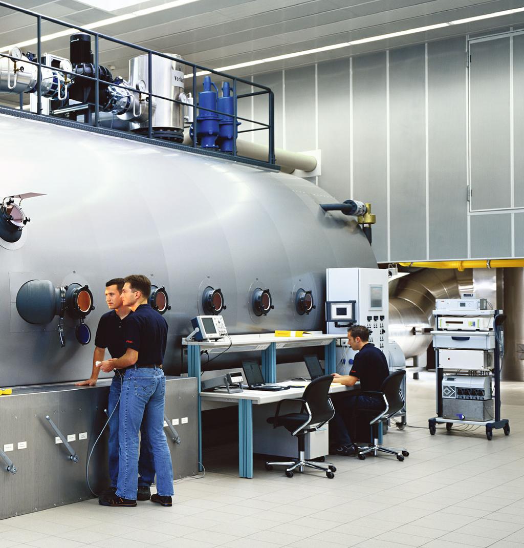
2 The powerful industrial burner with a modular construction arallel operation Air preheater Combustion-air fan Min. 5 mm sheet steel Max. 50 cm between stabilisers Fabric compensators are essential Air deflector Burner Combustion-air ducting Combustion air temperatures up to 250 C Weishaupt WK-series burners have been designed especially for industrial use. The modular design of the burners, coupled with their large capacity range, makes them ideally suited to a broad spectrum of special applications. Modular principle Weishaupt WK-series industrial burners are of modular design. That means the fan, pump station, and preheater station are all selected independently of the burner. This concept offers a high degree of flexibility in matching to the most diverse applications. Digital combustion management Digital combustion management ensures the simple and safe operation of combustion plant. Emissions are minimised and economy is maximised. Insulated burner housing The burner housing is fitted with internal insulation (optional extra on the ambientair versions of the WK 40 and 50). This significantly reduces the surface temperature of the housing during operation with preheated combustion air. The insulation also provides effective noise reduction. Heat recovery using preheated combustion air Many industrial processes create high flue-gas temperatures due to the high temperature of the medium used. A 2 heat exchanger in the flue can be used to reclaim a large amount of energy from these hot flue gases, increasing efficiency by up to 10 %. Weishaupt WK-series industrial burners can be operated with preheated combustionair temperatures of up to 250 C. Nozzle-head shut-off device At burner shutdown, or when changing over to gas operation, a safety shut-off device located in the oil atomising system shuts off the oil flow directly in the nozzle orifice, preventing the escape of any oil. Modulating operation Within its operating range, the burner s output is matched to the current heat demand. Reduced capacity at start-up The burners start at gas operation at a reduced ignition load (WK (G) MS > 17.5 MW with an additional pilot burner). This means that only a small quantity of gas flows into the combustion chamber. After the ignition phase, the burner drives to partial load. Controlled shutdown from partial load Controlled shutdown of the burner always takes place from the partial-load position, thus preventing impact on the gas main. Fuels Fuel oil EL (< 6 mm 2 /s at 20 C) in accordance with DIN Fuel oil S (< 60 mm 2 /s at 100 C) (< 700 mm 2 /s at 50 C) in accordance with DIN /-5 Natural gas E/LL LG B/ ermissible installation conditions Ambient temperature during operation: -15 to +40 C Humidity: max. 80 % relative humidty, no condensation Standard burner protection: I 54 Suitable for horizontal or vertical installation Standards conformity EN 267 and EN 676 ressure Equipment Directive, 97/2/EC Gas Appliance Directive, 2009/142/EC Machinery Directive, 2006/42/EC Electromagnetic Compatibility Directive, 2004/108/EC Low Voltage Directive, 2006/95/EC The burners are marked with a - CE mark - CE roduct ID No. - Type-test No.
 Full encapsulation (optional) A one-stop solution for")
3 Gas valve train and accessories Oil-supply accessories Combustion-air fans with/without VSD Lateral sound absorber (standard) Full encapsulation (optional) A one-stop solution for reliability

4 Digital combustion management: recise, simple, and reliable Setting via the control and display unit Digital combustion management means optimal combustion figures, continuously reproducible setpoints, and ease of use. Weishaupt WK-series burners are equipped as standard with electronic compound regulation and digital combustion management. Modern combustion technologies demand a precise and continually reproducible dosing of fuel and combustion air. Simple operation Setting and control of the burner is achieved using a control and display unit. This is linked to the combustion manager via a bus system, enabling the user-friendly setting of the burner. The control and display unit has a clear text display with a choice of languages. An English/Chinese dual-screen version is available as an option should a Chinesecharacter display be desired. Flexible communication options The integrated interface enables all necessary data and functions to be relayed to a master control system via, for example, ebus, Modbus RTU, Modbus TC/I, or rofibus-d. Measures for saving energy and increasing safety and reliability Electronic compound regulation with the W-FM 100 and 200 combustion managers facilitates the extremely precise, hysteresis-free setting of the burner. The burner can be adjusted for ideal combustion figures throughout its entire capacity range. This reduces flue gas losses and saves fuel. Variable speed drive reduces electrical consumption and facilitates a soft start of the combustion air fan. The use of VSD also reduces noise emissions by a considerable amount. O 2 trim saves fuel through a continual and extremely efficient optimisation of the combustion air. Different O 2 probes are available, providing suitable solutions for almost all fuels in applications with flue-gas temperatures below 00 C. Combined CO/O 2 control ensures an ultimate degree of safety. CO emissions are continually monitored and, if the defined limit is exceeded, the burner is operated with an increased amount of excess air for a short period of time before the O 2 trim returns the burner to its preset O 2 setpoint. Should external influences prevent a non-critical condition from being reached, then the burner will undergo a controlled shutdown. Digital combustion management overview W-FM 100 W-FM 200 Continuous operation > 24 h l l Capacity control for temperature or pressure Optional l O 2 trim with QGO20/21 O 2 probe Combined CO/O 2 control VSD Flue gas recirculation (temperature compensated) WK(G)MS 80 with gas ignition l Optional WKMS 80 with light-oil ignition l l SQM40/48/9... servomotors in electronic compound (max.) x 4 x 6 W-FC 4.0 flame monitoring l l W-FC 5.0/6.0 flame monitoring arallel burner firing (in conjunction with KS... controller) Two gaseous fuels (also in combination with a liquid fuel) Two liquid fuels with different calorific values Optional l l l l l l l x 2 l x 2 Integral valve proving (with gaseous fuels) l l Burner-mounted W-FM for combustion-air temperatures up to 40 C W-FM supplied loose (for panel mounting) for combustion-air temperatures up to 40 C Burner-mounted ABE for combustion-air temperatures up to 40 C ABE supplied loose (for panel mounting) for combustion-air temperatures up to 40 C W-FM and ABE supplied loose (for panel mounting) for combustion-air temperatures from 40 to 250 C l Optional l Optional l 1) l 1) Optional Optional Setpoint input (0)4-20 ma / 0-10 V Optional l Configurable analogue output X6 (rating / drive position / flame signal / medium temperature or pressure) ebus / Modbus RTU l l l l l 1) Not available with dual-screen Roman and Chinese-script version 4
 Burner with inbuilt digital combustion manager T")
 Setpoint input M O 2 module CO module Gas feed Oil")

 Modbus C / touchscreen visualisation System")

5 CO probe (max. 10 m) O 2 probe (QGO20) oder (max. 10 m) Burner with inbuilt digital combustion manager T 0-10 V 4-20 ma O 2 diffusion probe (QGO21 for heavy oil) Setpoint input M O 2 module CO module Gas feed Oil feed Air feed Regulating sleeve (air) Frequency convertor for variable speed drive Burner-mounted / panel-mounted control and display unit CAN bus (max. 100 m) Modbus C / touchscreen visualisation System networking via LC / DDC W-FM 200 combustion manager W-FM COM communications module Telecontrol via fixed/mobile phone network or internet 5


6 Limitless communications: flexible, reliable and simple Burner Control anel C / touchscreen visualisation W-FM50/54/100/200 combustion manager ABE control and display unit Optional dual-script display for W-FM 100/200 CAN bus Optional Modbus RTU Other burners System networking via LC / DDC rogramming cable Various bus systems, e.g. Modbus TC/I, rofilbus-d Commissioning support Fault analysis Data storage Gateway Modbus RTU W-FM COM communications module Other burners Camera LAN / W-LAN Digital / analogue inputs and outputs GSM aerial (optional) 6


7 BMS Worldwide SCADA Supervisory Control and Data Aquisition Laptop / tablet SMS Smartphone Various bus systems Various bus systems Monitoring and alarms LAN / W-LAN Read process and meter values Adjust setpoints Read fault and lockout history GSM / web server Controllable digital inputs and outputs 7

8 Emissions reduced by the multiflam principle Weishaupt s multiflam technology was designed for gas and dual-fuel burners. By using a patented LN mixing head, NO x emissions on WKseries burners can be reduced to extremely low levels. Weishaupt has set an all-new benchmark, achieving levels below 80 mg/m on gas and 120 mg/m on oil, subject to the combustion chamber geometry. Weishaupt s multiflam burners meet the world s toughest standards. In those countries with particularly stringent environmental legislation, such as Switzerland, multiflam industrial burners are market-sector leaders. Typical flame formation At the heart of Weishaupt s multiflam technology is a special mixing-assembly design which distributes the fuel among primary and secondary nozzles. This results in extremely efficient combustion thanks to recirculation of the flue gases directly at the mixing assembly. mg/m mg/m TA Luft (Germany) 1. BImschV (Germany) 10 to 20 MW TA Luft (Germany) 1. BImschV (Germany) 10 to 20 MW LRV (Switzerland) NO x LRV (Switzerland) NO x CO CO Gas Oil Typical emission levels for hot-water plant 8


9 Flame monitoring for demanding safety requirements Testing and optimisation using a software tool Weishaupt Flame Control (W-FC) is a reliable flame monitoring system designed for demanding safety requirements. W-FC 4.0 is for plant with multiple burners firing from the same direction into a single combustion chamber. The W-FC assembly utilises flame frequency to monitor each flame separately via a load-independent on and off threshold for each fuel. The CFC... flame sensor functions in series with the QRA7 flame sensor on the W-FM 100/200 combustion manager. Note: If a turndown in excess of >1:4 or single-burner operation is required, the higher specification W-FC 5.0 must be selected. burners firing from different directions into a single combustion chamber, and for process plant with various flame sources. The W-FC assembly monitors each flame separately via a loaddependent switching threshold for each fuel. This guarantees a distinct differentiation from extraneous sources. The CFC... flame sensor functions in parallel with the QRA7 flame sensor on the W-FM 200 combustion manager. This convenient, load-dependent setting of the on and off thresholds rests upon the electronic VLoad module, which can be configured using software. W-FC 6.0 is to monitor flame stability on plant with flue-gas recirculation for extreme NO x requirements. With this version, the QRA7 flame sensor monitors the flame while the CFC... controls the flue gas volume based on the stability of the flame to ensure safe operating conditions. In this way, reliability of operation with optimal emissions is achieved under varying conditions. The VLoad module enables a load-dependent switching threshold to be tailored to the operational situation. All versions meet EN 298 continuous operation requirements. W-FC 4.0 For classical parallel firing into a combustion chamber, with a maximum turndown of 4:1 W-FC 5.0 For firing into a combustion chamber from opposing directions, and individual/staged firing of multiple burners W-FC 5.0 For plant with various flame sources, such as waste and biomass incineration, process plant, etc. W-FC 5.0 is for plant with multiple W-FC 6.0 CFC... flame sensor Flame root Combustion zone CFC.. M FU M M M Amplitude W-FM 200 VLoad Frequency The constructive alignment of the CFC... allows the detection range to be optimised For plant with extreme NO x requirements, e.g. hot air, thermal fluid, etc 9
40-70 and WKG(L)80. ) The pilot line feeds a controlled amount of gas to the ignition electrodes for ignition.")
10 Ignition variants for every fuel and rating Variant A Standard ignition for liquid fuels on WKL/WKMS40-70 and WKL80. Liquid fuels are ignited directly by the high-voltage ignition electrodes. Variant B Standard ignition for gaseous fuels on WKG(L/MS)40-70 and WKG(L)80. ) The pilot line feeds a controlled amount of gas to the ignition electrodes for ignition. The main gas line is released and ignited after a short delay. Variant C Ignition option for liquid fuels on WKMS The pilot line feeds a controlled amount of LG to the ignition electrodes for ignition. This pilot flame ignites the main liquid fuel upon release. Ignition electrodes Ignition electrodes Ignition electrodes Oil nozzle Ignition pilot Oil nozzle Ignition pilot Oil nozzle Ignition variant A Ignition variant B with ignition pilot Ignition variant C with ignition pilot A B C Main gas line V1 V2 LG Gas valve train with ignition variant B Gas valve train with ignition variant C Weishaupt offers various ignition variants in order to ensure maximum reliability of ignition Variant G Optional light-oil ignition burner for liquid fuels on WKMS80. A reliable solution for the ignition of high-viscosity liquid fuels when gas is not available or not permitted. Ignition electrodes are used to ignite the oil injected by the pilot burner. The pilot burner is then used to ignite the main flame upon fuel release. Light-oil ignition burner G M Oil nozzle Ignition variant G with light-oil ignition burner 10
11 Variants D to F Optimal ignition for high-viscosity liquid fuels on WK(G)MS80, using a high-quality ignition burner This variant facilitates reliable ignition at a considerably reduced rating. An ignition electrode is used to ignite the pilot burner s gas mixture. The pilot burner is then used to ignite the main flame upon fuel release. A typical LG bottle (11/ kg) is adequate for ensuring reliable ignition. For example, an 11 kg LG bottle is sufficient for well over 00 ignitions. Flame monitoring is via a separate ionisation probe, which necessitates the use of a W-FM 200 combustion manager. This reliable solution was developed especially for heavy and special fuel oils with widely varying characteristics. It is also suitable for extreme ignitions, such as cold-starting plant that utilises pre-heated combustion air. Ignition electrode Ionisation electrode Front view: Ignition electrode Ignition variants D to F with ignition burner D W-MF E W-MF F W-MF LG Gas LG Main gas line V1 V2 Main gas line V1 V2 Gas valve train with ignition variant D Gas valve train with ignition variant E Gas valve train with ignition variant F A B C D E F G WK 4070 WK 80 WKL WKG ) / WKGL WKL WKMS WKMS WKG WKGMS WKGMS WKMS WKGMS < 17,5 MW WKGL < 17,5 MW l l l 2) l (WKMS) Accessories for variants C to E l l l 2) l 1) l 1) l 1) l 1) l l 1 2 l 1) l 1) Complete set (art No ) comprising: ressure regulator for 11/ kg LG bottle Hose-rupture protection m hose l Standard l Optional 1) W-FM 200 combustion manager required 2) 1SF version excluded ) WKG ZM(H)-LN burners ignite from main gas line - no pilot

-NR Gas-side NO X reduction compared to ZM version.")
-LN Low-NO X mixing assembly for gas burners. Further reduction in NO X emissions compared to 1LNversion burners.")

12 The right mixing assembly for every application Mixing assembly type Maintenance-friendly construction: On all burner versions, the standard-length combustion head (i.e. the flame tube and mixing assembly) can be inserted and withdrawn through the service opening in the burner housing. To further assist removal, the mixing assemblies on WK80 burners are guided by rail. Length Flame geometry Diameter Burner type Load-dependent air regulation in the M.A. ) Natural gas LG Fuels Light oil Heavy oil NO x Class 1) EN 676 EN 267 Natural gas LG Oil (light oil) ZM(H) Mixing assembly for gas, oil, and dual-fuel burners. For plant with no particular NO X requirements. WK WK 70/1 WK 80/ ZM(H)-NR Gas-side NO X reduction compared to ZM version. WK 50 WK 70/1 WK 70/ WK 80/ ZM(H)-1LN Low-NO X mixing assembly for gas and dual-fuel burners. For plant with gas and oil-side NO X requirements. WK 50 WK 70 2 ZM(H)-LN Low-NO X mixing assembly for gas burners. Further reduction in NO X emissions compared to 1LNversion burners. WK 40 WK 70 (ZMH)-LN Low-NO X mixing assembly for gas, oil, and dual-fuel burners. For plant with extremely low NO X limits. Lowest NO X emissions in comparison with all other versions. WK WK 70 WK 80 1) Combustion-air temperatures < 40 C 2) Minimum requirements for the combustion-chamber geometry must be agreed with Weishaupt s headquarters ) Mixing assembly 12
 Natural gas LG Fuels Light oil Heavy oil NO x Class 1) EN 676 EN 267 Natural gas LG Oil (light oil) ZM(H)-1SF Mixing assembly for gas, oil, and dual-fuel burners.")
 and for elongated, D-type combustion chambers in water-tube boilers with low cross-sectional loads (WKG80/4 to WKG80/6).")
13 Mixing assembly type Length Flame geometry Diameter Burner type Load-dependent air regulation in the M.A. ) Natural gas LG Fuels Light oil Heavy oil NO x Class 1) EN 676 EN 267 Natural gas LG Oil (light oil) ZM(H)-1SF Mixing assembly for gas, oil, and dual-fuel burners. Mixing assembly for extremely short combustion chambers in water-tube boilers. WK 40-80/ ZM(H) - VSF Mixing assembly for gas burners, type WKG80/4 to 80/6. Mixing assembly for extremely short combustion chambers (WKG80/4 and 80/5) and for elongated, D-type combustion chambers in water-tube boilers with low cross-sectional loads (WKG80/4 to WKG80/6). The flame geometry of the WKG80/4 and 80/5 can be optimised by internal fittings (circular blanks). 2) WK 80/4 WK 80/5 WK 80/6 2 Type tested / CSEI certified CSEI certified EN emission classes Fuel Natural Gas (EN 676) LG (EN 676) Light Oil (EN 267) Emission Class NO x emissions in mg/kwh Maximum turndown Burner Version Natural Gas/LG Light Oil HFO WK 40 / WK 50 ZM... 4 : 1 : 1 : 1 WK 70 / WK 80 ZM(H) / ZM(H)-NR / ZM(H)-1LN / ZM(H)-LN / ZM(H)-LN / ZM(H)-VSF 8 : 1 5 : 1.5 : 1 WK 70 / WK 80 ZM(H)-1SF 8 : 1 4 : 1 : 1 Basic conditions: Without excess air limitations. Combustion values not guaranteed throught the entire turndown range. All operational points must lie within the burner s capacity chart. Higher turndowns may be achievable in certain cases (subject to agreement with Weishaupt s headquarters). 1
14 Overview of capacities Gas burners Version ZM WKG natural-gas and LG burners Burner type Version Fuel Rating kw ZMH / ZM WK 40/1-A ZM(H) Nat. gas / 2200 LG / 2200 min. full load (kw) ZM/ZMH 1000 / 1000 WK 40/2-A ZM(H) Nat. gas / 000 LG / 000 WK 50/1-B ZM(H) Nat. gas / 4000 LG / 4000 WK 50/2-A ZM(H) Nat. gas / 6000 LG / 6000 WK 70/1-B ZM(H) Nat. gas / 7700 Version NR WKG natural-gas and LG burners Burner type Version Fuel Rating kw ZMH / ZM WK 50/1-B ZM(H)-NR Nat. gas / 4000 LG / 4000 min. full load (kw) ZM/ZMH 2000 / 2000 WK 50/2-A ZM(H)-NR Nat. gas / 6000 LG / 6000 WK 70/1-B ZM(H)-NR Nat. gas / 7700 LG / 7700 WK 70/-A ZM(H)-NR Nat. gas / LG / WK 80/-A ZM(H)-NR Nat. gas / LG / Version 1LN WKG natural-gas and LG burners Burner type Version Fuel Rating kw ZMH / ZM WK 50/1-B ZM(H)-1LN Nat. gas / 600 LG / 600 min. full load (kw) ZM/ZMH 2000 / 2000 WK 50/2-A ZM(H)-1LN Nat. gas / 5500 LG / 5500 WK 70/1-B ZM(H)-1LN Nat. gas / 7000 LG / 7000 WK 70/2-A ZM(H)-1LN Nat. gas / LG / Burner-selection criterion: The minimum full-load rating within a burner s capacity range corresponds to the maximum rating of the next smallest size of the same version burner. 14
15 Version LN WKG natural-gas burners Burner type Version Fuel Rating kw ZMH / ZM WK 40/2-A ZM(H)-LN Nat. gas / min. full load (kw) ZM 1800 / ZMH 1800 WK 70/1-B ZM(H)-LN Nat. gas / 7000 WK 70/2-A ZM(H)-LN Nat. gas / Version LN multiflam WKG natural-gas burners Burner type Version Fuel Rating kw ZMH / ZM WK 70/1-B (ZMH)-LN Nat. gas / LG / min. full load (kw) ZM/ZMH 5000 / 5000 WK 70/-A (ZMH)-LN Nat. gas / 1000 LG / 1000 WK 80/1-A (ZMH)-LN Nat. gas / LG / Version ZM 1SF WKG natural-gas and LG burners Burner type Version Fuel Rating kw ZMH / ZM WK 50/2-A ZM(H)-1SF Nat. gas / min. full load (kw) ZM 4000 / ZMH 200 WK 70/1-B ZM(H)-1SF Nat. gas / 8000 WK 70/2-A ZM(H)-1SF Nat. gas / Version ZM VSF WKG natural-gas and LG burners Burner type Version Fuel Rating kw ZMH / ZM WK 80/4 ZM(H)-VSF Nat. gas / LG / min. full load (kw) ZM/ZMH / 9600 WK 80/5 ZM(H)-VSF Nat. gas / WK 80/6 ZM(H)-VSF Nat. gas / 2000 Version ZM: Combustion-air temperatures up to 40 C Version ZMH: Combustion-air temperatures up to 100 C Version ZMH: Combustion-air temperatures up to 250 C See the planning and installation handbook for fan selection and arrangement, gas valve trains, special equipment, technical data, and dimensions. 15
16 Overview of capacities Oil burners Version ZM WKL and WKMS light and heavy-oil burners Burner type Version Fuel Rating kw ZMH / ZM WK 40/1-A ZM(H) Light oil / 2200 Heavy oil / 2200 min. full load (kw) ZM/ZMH 1200 / 1200 WK 40/2-A ZM(H) Light oil / 000 Heavy oil / 000 WK 50/1-B ZM(H) Light oil / 4000 Heavy oil / 4000 WK 50/2-A ZM(H) Light oil / 6000 Heavy oil / 6000 WK 70/1-B ZM(H) Light oil / 7700 Heavy oil / 7700 WK 70/-A ZM(H) Light oil / Heavy oil / WK 80/-A ZM(H) Light oil / Heavy oil / Version LN multiflam WKGL light-oil burners * Burner type Version Fuel Rating kw ZM WK 70/1-B* LN Light oil min. full load (kw) ZM 5000 WK 70/-A* LN Light oil WK 80/1-A* LN Light oil * LN-version WK 70 and WK 80 burners are not available as single-fuel oil burners. However, the WKGL dual-fuel burners are available in a special oil only execution without gas-side components. Refer to the price list for the appropriate price reduction. Version 1SF WKL and WKMS light and heavy-oil burners Burner type Version Fuel Rating kw ZMH / ZM WK 50/2-A ZM(H)-1SF Light oil / 6000 Heavy oil / 6000 min. full load (kw) ZM/ZMH 4000 / 200 WK 70/1-B ZM(H)-1SF Light oil / 8000 Heavy oil / 8000 WK 70/2-A ZM(H)-1SF Light oil / Heavy oil / WK 80/-A ZM(H)-1SF Light oil / Heavy oil /
17 Overview of capacities Dual-fuel burners Version ZM WKGL and WKGMS dual-fuel burners Burner type Version Fuel Rating kw ZMH / ZM WK 40/1-A ZM(H) Nat. gas / 2200 LG / 2200 Light oil / 2200 Heavy oil / 2200 min. full load (kw) ZM/ZMH 1000 / 1000 min. full load (kw) ZM/ZMH 1200 / 1200 WK 40/2-A ZM(H) Nat. gas / 000 LG / 000 Light oil / 000 Heavy oil / 000 WK 50/1-B ZM(H) Nat. gas / 4000 LG / 4000 Light oil / 4000 Heavy oil / 4000 WK 50/2-A ZM(H) Nat. gas / 6000 LG / 6000 Light oil / 6000 Heavy oil / 6000 WK 70/1-B ZM(H) Nat. gas / 7700 Light oil / 7700 Heavy oil / 7700 Burner-selection criterion: The minimum full-load rating within a burner s capacity range corresponds to the maximum rating of the next smallest size of the same version burner. Version ZM: Combustion air temperatures up to 40 C Version ZMH: Combustion air temperatures up to 250 C See the planning and installation handbook for fan selection and arrangement, gas valve trains, special equipment, technical data, and dimensions. 17
18 Overview of capacities Dual-fuel burners Version NR WKGL and WKGMS dual-fuel burners Burner type Version Fuel Rating kw ZMH / ZM WK 50/1-B ZM(H)-NR Nat. gas / 4000 LG / 4000 Light oil / 4000 Heavy oil / 4000 min. full load (kw) ZM/ZMH 000 / 2500 WK 50/2-A ZM(H)-NR Nat. gas / 6000 LG / 6000 Light oil / 6000 Heavy oil / 6000 WK 70/1-B ZM(H)-NR Nat. gas / 7700 LG / 7700 Light oil / 7700 Heavy oil / 7700 WK 70/-A ZM(H)-NR Nat. gas / LG / Light oil / Heavy oil / WK 80/-A ZM(H)-NR Nat. gas / LG / Light oil / Heavy oil / Version 1LN WKGL dual-fuel burners Burner type Version Fuel Rating kw ZMH / ZM WK 50/1-B ZM(H)-1LN Nat. gas / 600 LG / 600 Light oil / 600 min. full load (kw) ZM/ZMH 2000 / 2000 WK 50/2-A ZM(H)-1LN Nat. gas / 5500 LG / 5500 Light oil / 5500 WK 70/1-B ZM(H)-1LN Nat. gas / 7000 LG / 7000 Light oil / 7000 WK 70/2-A ZM(H)-1LN Nat. gas / LG / Light oil / Burner-selection criterion: The minimum full-load rating within a burner s capacity range corresponds to the maximum rating of the next smallest size of the same version burner. 18
19 Version LN multiflam WKGL dual-fuel burners Burner type Version Fuel Rating kw ZM WK 70/1-B LN Nat. gas LG Light oil min. full load (kw) ZM 5000 WK 70/-A LN Nat. gas LG Light oil WK 80/1-A LN Nat. gas LG Light oil Version 1SF WKGL and WKGMS dual-fuel burners Burner type Version Fuel Rating kw ZMH / ZM WK 70/1-B ZM(H)-1SF Nat. gas / 8000 Light oil / 8000 Heavy oil / 8000 min. full load (kw) ZM/ZMH 6000 / 5000 WK 70/2-A ZM(H)-1SF Nat. gas / Light oil / Heavy oil / WK 80/-A ZM(H)-1SF Nat. gas / Light oil / Heavy oil / Version ZM: Combustion air temperatures up to 40 C Version ZMH: Combustion air temperatures up to 250 C See the planning and installation handbook for fan selection and arrangement, gas valve trains, special equipment, technical data, and dimensions. 19
20 Burner selection based on steam boiler rating Steam rate t/h 15 Steam pressure bar Steam temperature C Feed-water temperature C Firing rate MW Oil flow rate (LHV=11.86 kwh/kg) kg/h Gas flow rate (LHV =10.5 kwh/m³) m³/h Min. gas supply pressure * mbar Gas flow rate (LHV = 8.8 kwh/m³) m³/h Min. gas supply pressure * mbar Burner: Oil burner WK(L/MS) 70/ ZM 70/ ZM 70/ ZM 70/ ZM 70/ ZM 70/ ZM 80/ ZM 70/ ZM 70/ ZM 70/ ZM 70/ ZM 70/ ZM 80/ ZM 70/ ZM Gas burner WKG.. 70/ ZM-NR 70/ ZM-NR 70/ ZM-NR 70/ ZM-NR 70/ ZM-NR 70/ ZM-NR 80/ ZM-NR 70/ ZM-NR 70/ ZM-NR 70/ ZM-NR 70/ ZM-NR 70/ ZM-NR 80/ ZM-NR 70/ ZM-NR 80/4 ZM-VSF 80/4 ZM-VSF Dual-fuel burner WKGL.. 70/ ZM-NR 70/ ZM-NR 70/ ZM-NR 70/ ZM-NR 70/ ZM-NR 70/ ZM-NR 80/ ZM-NR 70/ ZM-NR 70/ ZM-NR 70/ ZM-NR 70/ ZM-NR 70/ ZM-NR 80/ ZM-NR 70/ ZM-NR WKGMS.. 70/ ZM-NR 70/ ZM-NR 70/ ZM-NR 70/ ZM-NR 70/ ZM-NR 70/ ZM-NR 80/ ZM-NR 70/ ZM-NR 70/ ZM-NR 70/ ZM-NR 70/ ZM-NR 70/ ZM-NR 80/ ZM-NR 70/ ZM-NR Combustion air fan: Air volume m³/h Steam rate t/h 20 Steam pressure bar Steam temperature C Feed-water temperature C Firing rate MW Oil flow rate (LHV=11.86 kwh/kg) kg/h Gas flow rate (LHV =10.5 kwh/m³) m³/h Min. gas supply pressure * mbar Gas flow rate (LHV = 8.8 kwh/m³) m³/h Min. gas supply pressure * mbar Burner: Oil burner WK(L/MS) 80/ ZM 80/ ZM 80/ ZM 80/ ZM 80/ ZM 80/ ZM 80/ ZM 80/ ZM 80/ ZM 80/ ZM 80/ ZM 80/ ZM 80/ ZM 80/ ZM Gas burner WKG.. 80/ ZM-NR 80/ ZM-NR 80/ ZM-NR 80/ ZM-NR 80/ ZM-NR 80/ ZM-NR 80/ ZM-NR 80/ ZM-NR 80/ ZM-NR 80/ ZM-NR 80/ ZM-NR 80/ ZM-NR 80/ ZM-NR 80/ ZM-NR 80/4 ZM-VSF 80/4 ZM-VSF 80/4 ZM-VSF 80/4 ZM-VSF 80/4 ZM-VSF 80/4 ZM-VSF 80/4 ZM-VSF 80/4 ZM-VSF 80/4 ZM-VSF 80/4 ZM-VSF 80/4 ZM-VSF 80/4 ZM-VSF 80/4 ZM-VSF 80/4 ZM-VSF Dual-fuel burner WKGL.. 80/ZM-NR 80/ZM-NR 80/ZM-NR 80/ZM-NR 80/ZM-NR 80/ZM-NR 80/ZM-NR 80/ZM-NR 80/ZM-NR 80/ZM-NR 80/ZM-NR 80/ZM-NR 80/ZM-NR 80/ZM-NR WKGMS.. 80/ZM-NR 80/ZM-NR 80/ ZM-NR 80/ZM-NR 80/ ZM-NR 80/ZM-NR 80/ZM-NR 80/ZM-NR 80/ZM-NR 80/ZM-NR 80/ZM-NR 80/ZM-NR 80/ZM-NR 80/ZM-NR Combustion air fan: Air volume m³/h Steam rate t/h 25 Steam pressure bar Steam temperature C Feed-water temperature C Firing rate MW Oil flow rate (LHV=11.86 kwh/kg) kg/h Gas flow rate (LHV =10.5 kwh/m³) m³/h Min. gas supply pressure * mbar Gas flow rate (LHV = 8.8 kwh/m³) m³/h Min. gas supply pressure * mbar Burner: Oil burner WK(L/MS) 80/ ZM 80/ ZM 80/ ZM 80/ ZM 80/ ZM 80/ ZM 80/ ZM 80/ ZM 80/ ZM 80/ ZM 80/ ZM 80/ ZM 80/ ZM 80/ ZM Gas burner WKG.. 80/ ZM-NR 80/ ZM-NR 80/ ZM-NR 80/ ZM-NR 80/ ZM-NR 80/ ZM-NR 80/ ZM-NR 80/ ZM-NR 80/ ZM-NR 80/ ZM-NR 80/ ZM-NR 80/ ZM-NR 80/ ZM-NR 80/ ZM-NR 80/4ZM-VSF 80/4ZM-VSF 80/4ZM-VSF 80/4ZM-VSF 80/4ZM-VSF 80/4ZM-VSF 80/4ZM-VSF 80/4ZM-VSF 80/4ZM-VSF 80/4ZM-VSF 80/4ZM-VSF 80/4 ZM-VSF 80/4ZM-VSF 80/4ZM-VSF Dual-fuel burner WKGL.. 80/ ZM-NR 80/ ZM-NR 80/ ZM-NR 80/ ZM-NR 80/ ZM-NR 80/ ZM-NR 80/ ZM-NR 80/ ZM-NR 80/ ZM-NR 80/ ZM-NR 80/ ZM-NR 80/ ZM-NR 80/ ZM-NR 80/ ZM-NR WKGMS.. 80/ ZM-NR 80/ ZM-NR 80/ ZM-NR 80/ ZM-NR 80/ ZM-NR 80/ ZM-NR 80/ ZM-NR 80/ ZM-NR 80/ ZM-NR 80/ ZM-NR 80/ ZM-NR 80/ ZM-NR 80/ ZM-NR 80/ ZM-NR Combustion air fan: Air volume m³/h *) Total resistance < 0 mbar (boiler, flue-gas heat exchanger, and flue gas system) o. a. = on application Saturated steam Superheated steam 20
21 Guidelines at 98 % boiler efficiency Installation altitude < 500 m, combustion-air temperature < 40 C Steam rate t/h 0 Steam pressure bar Steam temperature C Feed-water temperature C Firing rate MW Oil flow rate (LHV=11.86 kwh/kg) kg/h Gas flow rate (LHV =10.5 kwh/m³) m³/h Min. gas supply pressure * mbar Gas flow rate (LHV = 8.8 kwh/m³) m³/h Min. gas supply pressure * mbar Burner: Oil burner WK(L/MS) 80/ ZM 80/ ZM 80/ ZM 80/ ZM 80/ ZM 80/ ZM 80/ ZM Gas burner WKG.. 80/ ZM-NR 80/ ZM-NR 80/ ZM-NR 80/ ZM-NR 80/5 ZM-VSF 80/5 ZM-VSF 80/5 ZM-VSF 80/5 ZM-VSF 80/ ZM-NR 80/ ZM-NR 80/5 ZM-VSF 80/ ZM-NR 80/5 ZM-VSF 80/5 ZM-VSF 80/4 ZM-VSF 80/4 ZM-VSF 80/4 ZM-VSF 80/4 ZM-VSF 80/4 ZM-VSF 80/4 ZM-VSF 80/4 ZM-VSF Dual-fuel burner WKGL.. 80/ ZM-NR 80/ ZM-NR 80/ ZM-NR 80/ ZM-NR 80/ ZM-NR 80/ ZM-NR 80/ ZM-NR WKGMS.. 80/ ZM-NR 80/ ZM-NR 80/ ZM-NR 80/ ZM-NR 80/ ZM-NR 80/ ZM-NR 80/ ZM-NR Combustion air fan: Air volume m³/h Steam rate t/h 5 Steam pressure bar Steam temperature C Feed-water temperature C Firing rate MW Oil flow rate (LHV=11.86 kwh/kg) kg/h Gas flow rate (LHV =10.5 kwh/m³) m³/h Min. gas supply pressure * mbar Gas flow rate (LHV = 8.8 kwh/m³) m³/h Min. gas supply pressure * mbar Burner: Oil burner WK(L/MS) Gas burner WKG.. 80/5 ZM-VSF 80/5 ZM-VSF 80/5 ZM-VSF 80/5 ZM-VSF 80/5 ZM-VSF 80/5 ZM-VSF 80/6 ZM-VSF 80/6 ZM-VSF 80/5 ZM-VSF 80/5 ZM-VSF 80/5 ZM-VSF 80/5 ZM-VSF 80/6 ZM-VSF 80/6 ZM-VSF 80/6 ZM-VSF 80/6 ZM-VSF Dual-fuel burner WKGL.. WKGMS.. Combustion air fan: Air volume m³/h Steam rate t/h 40 Steam pressure bar Steam temperature C Feed-water temperature C Firing rate MW Oil flow rate (LHV=11.86 kwh/kg) kg/h Gas flow rate (LHV =10.5 kwh/m³) m³/h Min. gas supply pressure * mbar Gas flow rate (LHV = 8.8 kwh/m³) m³/h o. a. o. a. o. a o. a. o. a. o. a. Min. gas supply pressure * mbar o. a. o. a. o. a o. a. o. a. o. a. Burner: Oil burner WK(L/MS) Gas burner WKG.. 80/6ZM-VSF 80/5ZM-VSF 80/6ZM-VSF 80/5ZM-VSF 80/6ZM-VSF 80/6ZM-VSF 80/6ZM-VSF 80/6ZM-VSF 80/5ZM-VSF 80/6ZM-VSF 80/6ZM-VSF 80/6ZM-VSF 80/6ZM-VSF 80/6ZM-VSF 80/6ZM-VSF Dual-fuel burner WKGL.. WKGMS.. Combustion air fan: Air volume m³/h *) Total resistance < 0 mbar (boiler, flue-gas heat exchanger, and flue gas system) o. a. = on application Saturated steam Superheated steam 21
22 Burner selection based on steam boiler rating Steam rate t/h 15 Steam pressure bar Steam temperature C Feed-water temperature C Firing rate MW Oil flow rate (LHV=11.86 kwh/kg) kg/h Gas flow rate (LHV =10.5 kwh/m³) m³/h Min. gas supply pressure * mbar Gas flow rate (LHV = 8.8 kwh/m³) m³/h Min. gas supply pressure * mbar Burner: Oil burner WK(L/MS) 70/ ZM 70/ ZM 70/ ZM 70/ ZM 80/ ZM 70/ ZM 80/ ZM 80/ ZM 70/ ZM 70/ ZM 80/ ZM 70/ ZM 80/ ZM 80/ ZM Gas burner WKG.. 70/ NR 70/ NR 70/ NR 70/ NR 80/ NR 70/ NR 80/ NR 80/ NR 70/ NR 70/ NR 80/ NR 70/ NR 80/ NR 80/ NR Dual-fuel burner WKGL.. 70/ NR 70/ NR 70/ NR 70/ NR 80/ NR 70/ NR 80/ NR 80/ NR 70/ NR 70/ NR 80/ NR 70/ NR 80/ NR 80/ NR WKGMS.. 70/ NR 70/ NR 70/ NR 70/ NR 80/ NR 70/ NR 80/ NR 80/ NR 70/ NR 70/ NR 80/ NR 70/ NR 80/ NR 80/ NR Combustion air fan: Air volume m³/h Steam rate t/h 20 Steam pressure bar Steam temperature C Feed-water temperature C Firing rate MW , Oil flow rate (LHV=11.86 kwh/kg) kg/h Gas flow rate (LHV =10.5 kwh/m³) m³/h Min. gas supply pressure * mbar Gas flow rate (LHV = 8.8 kwh/m³) m³/h Min. gas supply pressure * mbar Burner: Oil burner WK(L/MS) 80/ ZM 80/ ZM 80/ ZM 80/ ZM 80/ ZM 80/ ZM 80/ ZM 80/ ZM 80/ ZM 80/ ZM 80/ ZM 80/ ZM 80/ ZM 80/ ZM Gas burner WKG.. 80/ NR 80/ NR 80/ NR 80/ NR 80/ NR 80/ NR 80/ NR 80/ NR 80/ NR 80/ NR 80/ NR 80/ NR 80/ NR 80/ NR 80/4 VSF 80/4 VSF 80/4 VSF 80/4 VSF 80/4 VSF 80/4 VSF 80/4 VSF 80/4 VSF 80/4 VSF 80/4 VSF 80/4 VSF 80/4 VSF 80/4 VSF 80/4 VSF Dual-fuel burner WKGL.. 80/ NR 80/ NR 80/ NR 80/ NR 80/ NR 80/ NR 80/ NR 80/ NR 80/ NR 80/ NR 80/ NR 80/ NR 80/ NR 80/ NR WKGMS.. 80/ NR 80/ NR 80/ NR 80/ NR 80/ NR 80/ NR 80/ NR 80/ NR 80/ NR 80/ NR 80/ NR 80/ NR 80/ NR 80/ NR Combustion air fan: Air volume m³/h Steam rate t/h 25 Steam pressure bar Steam temperature C Feed-water temperature C Firing rate MW Oil flow rate (LHV=11.86 kwh/kg) kg/h Gas flow rate (LHV =10.5 kwh/m³) m³/h Min. gas supply pressure * mbar Gas flow rate (LHV = 8.8 kwh/m³) m³/h Min. gas supply pressure * mbar Burner: Oil burner WK(L/MS) 80/ ZM 80/ ZM 80/ ZM 80/ ZM 80/ ZM 80/ ZM - 80/ ZM 80/ ZM 80/ ZM 80/ ZM 80/ ZM - 80/ ZM Gas burner WKG.. 80/ NR 80/ NR 80/ NR 80/ NR 80/ NR 80/ NR 80/5 VSF 80/ NR 80/ NR 80/ NR 80/ NR 80/ NR 80/5 VSF 80/ NR 80/4 VSF 80/4 VSF 80/4 VSF 80/4 VSF 80/4 VSF 80/4 VSF 80/4 VSF 80/4 VSF 80/4 VSF 80/4 VSF 80/4 VSF 80/4 VSF Dual-fuel burner WKGL.. 80/ NR 80/ NR 80/ NR 80/ NR 80/ NR 80/ NR - 80/ NR 80/ NR 80/ NR 80/ NR 80/ NR - 80/ NR WKGMS.. 80/ NR 80/ NR 80/ NR 80/ NR 80/ NR 80/ NR - 80/ NR 80/ NR 80/ NR 80/ NR 80/ NR - 80/ NR Combustion air fan: Air volume m³/h *) Total resistance < 0 mbar (boiler, flue-gas heat exchanger, and flue gas system) o. a. = on application Saturated steam Superheated steam 22
23 Guidelines at 92 % boiler efficiency Installation altitude < 500 m, combustion-air temperature < 40 C Steam rate t/h 0 Steam pressure bar Steam temperature C Feed-water temperature C Firing rate MW Oil flow rate (LHV=11.86 kwh/kg) kg/h Gas flow rate (LHV =10.5 kwh/m³) m³/h Min. gas supply pressure * mbar Gas flow rate (LHV = 8.8 kwh/m³) m³/h Min. gas supply pressure * mbar Burner: Oil burner WK(L/MS) 80/ ZM 80/ ZM 80/ ZM Gas burner WKG.. 80/5 ZM-VSF 80/ ZM-NR 80/5 ZM-VSF 80/ ZM-NR 80/5 ZM-VSF 80/5 ZM-VSF 80/5 ZM-VSF 80/5 ZM-VSF80/5 ZM-VSF 80/ ZM-NR 80/5 ZM-VSF 80/5 ZM-VSF 80/5 ZM-VSF 80/5 ZM-VSF 80/4 ZM-VSF 80/4 ZM-VSF 80/6 ZM-VSF 80/4 ZM-VSF 80/6 ZM-VSF Dual-fuel burner WKGL / ZM-NR 80/ ZM-NR 80/ ZM-NR WKGMS.. 80/ ZM-NR 80/ ZM-NR 80/ ZM-NR Combustion air fan: Air volume m³/h Steam rate t/h 5 Steam pressure bar Steam temperature C Feed-water temperature C Firing rate MW Oil flow rate (LHV=11.86 kwh/kg) kg/h Gas flow rate (LHV =10.5 kwh/m³) m³/h Min. gas supply pressure * mbar Gas flow rate (LHV = 8.8 kwh/m³) m³/h o. a. o. a o. a. o. a. Min. gas supply pressure * mbar o. a. o. a o. a. o. a. Burner: Oil burner WK(L/MS) Gas burner WKG.. 80/5 ZM-VSF 80/5 ZM-VSF 80/5 ZM-VSF 80/5 ZM-VSF 80/6 ZM-VSF 80/6 ZM-VSF 80/6 ZM-VSF 80/6 ZM-VSF 80/5 ZM-VSF 80/5 ZM-VSF 80/6 ZM-VSF 80/6 ZM-VSF 80/6 ZM-VSF 80/6 ZM-VSF 80/6 ZM-VSF Dual-fuel burner WKGL.. WKGMS.. Combustion air fan: Air volume m³/h Steam rate t/h 40 Steam pressure bar Steam temperature C Feed-water temperature C Firing rate MW Oil flow rate (LHV=11.86 kwh/kg) kg/h Gas flow rate (LHV =10.5 kwh/m³) m³/h Min. gas supply pressure * mbar Gas flow rate (LHV = 8.8 kwh/m³) m³/h o. a. 205 o. a. o. a. o. a. o. a. o. a. o. a. Min. gas supply pressure * mbar o. a. 500 o. a. 500 o. a. o. a. 500 o. a. Burner: Oil burner WK(L/MS) Gas burner WKG.. 80/6 ZM-VSF 80/6 ZM-VSF 80/6 ZM-VSF 80/6 ZM-VSF 80/6 ZM-VSF 80/6 ZM-VSF 80/6 ZM-VSF 80/6 ZM-VSF Dual-fuel burner WKGL.. WKGMS.. Combustion air fan: Air volume m³/h *) Total resistance < 0 mbar (boiler, flue-gas heat exchanger, and flue gas system) o. a. = on application Saturated steam Superheated steam 2
24 Correctly sized gas valve trains save money and trouble Low-pressure gas supply Rating Q F WKG(L) Δ WKG Δ Burner Burner MW ZM-NR mbar ZM-VSF mbar Nat. gas E LHV = 10.5 kwh/mn ; d = / / / / / / 1 80/ / 80/ / 7 80/ / 41 80/ / 45 80/ / 50 80/ / 55 80/ / 61 80/ / 67 80/ / 74 80/ / / / / / / / / / /6 45 Nat. gas LL LHV = 8.8 kwh/mn ; d = / / / / / / 1 80/ / 80/ / 7 80/ / 41 80/ / 45 80/ / 50 80/ / 55 80/ / 61 80/ / 67 80/ / 74 80/ / / / / / / / / / /6 45 FRS regulator E <00 mbar Gas shut-off valve assembly DMV - Dungs VGD - Siemens DN80 DN100 DN125 DN150 E A E A E A E A mbar mbar mbar mbar mbar mbar mbar mbar SK25 regulator E <60 mbar Gas shut-off valve assembly VGD - Siemens DN125 DN150 E A E A mbar mbar mbar mbar o. a. o. a. o. a. o. a. o. a. o. a ATTENTION NOTE The overall resistance (combustion chamber and flue gas resistance) in mbar must be added to the minimum gas pressure determined from the above chart. 24
25 High-pressure gas supply Rating High-pressure regulator E mbar 1) Gas shut-off valve assembly DMV - Dungs VGD - Siemens Q F WKG(L) Δ WKG Δ Burner Burner MW ZM-NR mbar ZM-VSF mbar Nat. gas E LHV = 10.5 kwh/mn ; d = / / / / / / 1 80/ / 80/ / 7 80/ / 41 80/ / 45 80/ / 50 80/ / 55 80/ / 61 80/ / 67 80/ / 74 80/ / / / / / / / / / /6 45 Nat. gas LL LHV = 8.8 kwh/mn ; d = / / / / / / 1 80/ / 80/ / 7 80/ / 41 80/ / 45 80/ / 50 80/ / 55 80/ / 61 80/ / 67 80/ / 74 80/ / / / / / / / / / /6 45 DN80 DN100 DN125 DN150 E A E A E A E A mbar mbar mbar mbar mbar mbar mbar mbar O F = Burner rating, E = ressure before ball valve, A = Regulated gas pressure, o. a. = on application E / A see page 28/29, 1) See accessories list for special 0.5-4/5/10 bar regulators and spring selections >240 mbar See planning handbook for LG selection values up to 22 MW. 25
26 Fuel systems Oil burners WKL40, integral pump WKMS40, integral pump and preheater V 115V 115V M 20V 115V M M M WKL50, 70, 80 WKMS50, 70, V 115V 20V 115V M 115V M M M a 14 1a 14 26
27 WKL multiflam Light-oil ignition burner, WKMS b b 115V 115V 115V 115V M M M a a LG ignition pilot, WKMS 40 to LG LG LG Oil-firing burner with gas ignition LG ignition burner, WKMS LG Oil-firing burner with gas ignition Oil pump 1a External pump station with pressure maintenance 2 Oil preheater Strainer 4 Temperature sensor in supply 5 Temperature sensor in return 6 Low-pressure switch 7 High-pressure switch 8 Solenoid valve in supply (fitted in the direction of flow) 9 Solenoid valve in return (fitted against the direction of flow) 10 Bypass solenoid valve (normally open) 11 Solenoid valve assembly 11a Nozzle head with secondary nozzles 11b Nozzle head with primary nozzle 12 Oil regulator 1 ressure regulating valve 14 Filter 15 LG bottle (supplied by others) 16 LG pressure regulator (accessory) 17 Hose rupture protection (accessory) 18 Ball valve 19 ressure gauge with push-button valve 20 Low-gas-pressure switch 21 High-gas-pressure switch 22 W-MF multi-function assembly 2 DMV gas solenoid valve assembly 24 FRS gas pressure regulator 25 Burner 26 Sub-assembly fitted to burner at works 27
28 Fuel systems Gas and dual-fuel burners A B C Gas side, WKG(L) 40 80, WKGMS Versions ZM / NR / 1LN / LN / 1SF / VSF WK burner size Nominal valve train size Gas shut-off assembly type Low-pressure supply with FRS governor Low-pressure supply with SK regulator on VGD assembly High-pressure supply with High-pressure regulator A E 9b A 9b E 00 mbar A 200 mbar E 60 mbar A 250 mbar 2) E > mbar 1) A 210 / 240 mbar 1) 1 2 a 4a 4b Gas side, WKG(L) 80 Versions NR / LN / 1SF / VSF 1 1/2 W-MF 512 l l 9b 9b DMV l l 525/12 B E A DN 65 DMV l l 5065/12 DN 80 DMV l l 5080/ a 4d 5 8 2) Spring for A > 250 mbar on application DN 100 DMV l l 5100/12 Gas side, WKG(L) 40 80, WKGMS Versions ZM / NR / 1LN / LN / 1SF / VSF 9a 9a DN 125 DN 150 VGD l l l VGD l l l C E A E = ressure before ball valve A = Regulated pressure l Standard l Optional SK25 regulator for burner type WK 80, including stabilisation section (suitable for horizontal burner installations only) 1 2 b 4c ) See accessories list for special 0.5-4/5/10 bar regulators and spring selections > 240 mbar 28
29 8 8 Gas side, WKG Version LN Gas side, WKGMS 80 ) Versions ZM / NR / 1SF a 4e a 9b 11 LG E A 9b E A V1 V2 1 2 a 4a 4b a 4b Gas side, WKGMS 80 ) Versions ZM / NR / 1SF E a LG 9b 1 2 Gas side, WKGMS 80 ) Versions ZM / NR / 1SF a 4e 5 4e 5 V1 V a 4d5 14 A Ball valve 2 Gas filter a Low-pressure regulator b High-pressure regulator incl. SAV / SBV 4a High-gas-pressure switch on screwed valve trains (mounted immediately after the low-pressure regulator) 4b High-gas-pressure switch on flanged valve trains (mounted on the inlet of the valve assembly) 4c High-gas-pressure switch on screwed and flanged valve trains (mounted on the outlet-side of the high-pressure regulator assembly) 4d High-gas-pressure switch on flanged valve trains (mounted on the outlet of the VGD assembly) 4e High-gas-pressure switch (mounted on the LG ignition-burner assembly) 5 Low-gas-pressure switch 6 Valve-proving pressure switch 7 Double shut-off valve assembly 8 Gas butterfly valve 9a ressure gauge with push-button valve (standard) 9b ressure gauge with push-button valve (accessory) 10 ilot-line solenoid valve 11 Burner 12 LG pressure regulator (accessory) 1 Hose rupture protection (accessory) 14 W-MF multi-function assembly 15 LG tank (by others) 16 Sub-assembly fitted to burner at works LG 9a 9a Layout of the valve train (vertical burner installation) The offset gas butterfly and solenoid valves option is strongly recommended because of the increased heat radiation due to the vertical boiler design and the high temperatures of media such as thermal fluid. Note: This variant is not available with the SK25 pressure regulator due to the need for a stabilisation section. E A V1 V2 Compensator To enable a tension free mounting of the valve train, the fitting of a compensator is recommended. Optional thermal shut off (when required by local regulations) Integrated into the ball valve on screwed valve trains. A separate component with HTB seals fitted before the ball valve on flanged valve trains. 1 2 b 4c ) LG or natural gas pilot line as required (see page 11 for options). 29
 RD 2 cooling-air fan 120 ZMH-.. Ø90 l 1 l 14 Type DN l1 l2 l l4 l5 l6 l7 l8 l9 l10 l11 l12 l1 l14 h1 h2 h WK.. 40 65 88 116 116 1 40 140 226 6 264 68 452 1046 21 255 444 84 400 WK.")
30 Key dimensions at a glance Ambient combustion air (ZM...) l G /4 h DN h 1 h 2 60 ZM-.. l 1 l 2 Optional compensator l 6 l 4 l 5 l 9 l 10 l 7 l 8 h l 11 l12 reheated combustion air (ZMH...) RD 2 cooling-air fan 120 ZMH-.. Ø90 l 1 l 14 Type DN l1 l2 l l4 l5 l6 l7 l8 l9 l10 l11 l12 l1 l14 h1 h2 h WK WK WK WK Weishaupt reserve the right to make changes in light of future developments. Additional burner dimensions and oil-side connection details are available on request. 0
31 Heat-exchanger mounting l Typ Ausf. d1 d2 d l15 1) WK.. 40/1 ZM(H) WK.. 40/2 ZM(H) WK.. 40/2 ZM(H)-LN d 1 d 2 d WK.. 50/1 ZM(H)-NR/ZM(H)-1LN WK.. 50/2 ZM(H)-NR WKG(L) 50/2 ZM(H)-1LN WKL(MS) 50/1 ZM(H) WKL(MS) 50/2 ZM(H) WK.. 50/2 ZM(H)-1SF The space between the combustion head and the refractory should be filled with a resiliant, non-solid insulating material, such as Cerafelt. Maintenance-friendly combustion head: On all burner versions, the standard-length combustion head can be inserted and withdrawn through the service opening in the burner housing. 1) Combustion head extension on application. WK.. 70/1 ZM(H)-NR WK.. 70/2 ZM(H)-NR WK.. 70/ ZM(H)-NR WKG 70/1 ZM(H)-LN WKG(L) 70/1 ZM(H)-1LN WKG(L) 70/2 ZM(H)-LN/ZM(H)-1LN WKG(L) 70/1 ZM(H)-LN WKG(L) 70/ ZM(H)-LN WK.. 70/1 ZM(H)-1SF WK.. 70/2 ZM(H)-1SF WKL(MS) 70/1 ZM(H) WKL(MS) 70/2 ZM(H) WK.. 80/ ZM(H)-NR WKG(L) 80/1 ZM(H)-LN WK.. 80/ ZM(H)-1SF WKG 80/4-5 ZM(H)-VSF WKG 80/6 ZM(H)-VSF Mounting-plate drilling dimensions Ø(412) 60 Ø(560) 490 Ø75 Ø875 Ø M12 M12 M16 0 M16 0 Ø290 Ø90 Ø50 Ø640 (WK80/-5) Ø650 (WK80/6) WK 40 WK 50 WK 70 WK 80 1
32 Overview of options, installation positions, and weights Vertically firing Weishaupt burners have been especially designed for use on vertical plant, such as steam boilers, thermal fluid heaters, and process applications. Vertical execution l 18 Reliable operation: Safety-critical components such as the gas butterfly valve, stepping motor, gas shut-off valves, and gas pressure switches, are securely located away from high-temperature zones to ensure their reliable operation. The offset position of the gas pilot valve protects it from high levels of radiant heat from the heat exchanger. 1 h 6 h 4 l 16 Optional l 19 l 18 1 h 5 h 6 l 17 Optional Extended option (with accessory components) l 20 2
33 Vertical-execution dimensions Burner flange to butterfly Gas valve assembly valve outlet DN DN l16 1) l17 l18 l19 1) l20 h4 h5 h6 WK /2" ) 105 2) " ) ) ) ) ) ) WK " ) ) ) ) ) 162 2) ) 147 2) WK ) ) ) ) ) 169 2) ) 172 2) WK ) ) ) 160 2) ) Including horizontal intermediate flange (not shown) 2) Including concentric reducer (not shown) Burner weights (kg) WKG WKL WKMS WKGL WKGMS WK ) / 125 5) 165,4) / 10 5,6) 150 ) / 15 5) 170,4) / 140 5,6) WK WK WK ) Burner-mounted oil pump 4) Burner-mounted oil preheater 5) Separate oil pump 6) Separate oil preheater Combustion-air fan: housing arrangement Type L 90 Type L 180 Type L 270 Type L 60 Type R 90 Type R 180 Type R 270 Type R 60 Viewed from the drive-side of the fan.

34 Combustion test chamber at the Schwendi Research & Development Institute 4
35 5

36 Max Weis haupt GmbH Schwen di Te l Fax haupt.de rint No , March 2014 rinted in Germany. All rights reserved. Weishaupt service worldwide: Weishaupt worldwide Branch offices across Germany and numerous subsidiary companies, representatives and agents across the world provide local support. Germany: Augsburg Berlin Bremen Cologne Dortmund Dresden Erfurt Frankfurt Freiburg Hamburg Hanover Karlsruhe Kassel Koblenz Leipzig Mannheim Munich Münster Neuss Nuremberg Regensburg Reutlingen Rostock Schwendi Siegen Stuttgart Trier Wangen Würzburg Subsidiaries: Belgium Bosnia Brasil Canada Croatia Czech Republic Denmark France Hungary Italy oland Romania Serbia Slovakia Slovenia South Africa Sweden Switzerland (E) United Kingdom USA Representation: Bulgaria China Lithuania Agencies: Algeria Australia Austria Bangladeh Cyprus Egypt Estonia Finland Greece India Indonesia Iran Ireland Israel Japan Jordan Korea (South) Kuwait Latvia Lebanon Luxembourg Malaysia Macedonia Moldova Morocco Netherlands New Zealand Nigeria Norway akistan hilippines ortugal Russia Singapore Spain Switzerland (W) Syria Taiwan Thailand Tunisia Turkey Ukraine UAE Vietnam
Weishaupt WKGL70 dual fuel burner Version 3LN (Low NO x ) multiflam 1/2003 GB
 multiflam 1/2003 GB") Weishaupt WKGL70 dual fuel burner Version 3LN (Low NO x ) multiflam 1/2003 GB Description Weishaupt WK series industrial burners have been especially designed for industrial capacity ranges. The construction
Weishaupt WKGL70 dual fuel burner Version 3LN (Low NO x ) multiflam 1/2003 GB Description Weishaupt WK series industrial burners have been especially designed for industrial capacity ranges. The construction
product Information on oil, gas and dual fuel burners Industrial burners 1,000 11,700 kw flexible and reliable
 product Information on oil, gas and dual fuel burners Minimale Industrial Emissionswerte burners mit Gas Industrial burners 1, 11,7 kw flexible and reliable Weishaupt Industrial Burners: Flexible and reliable
product WM 20 for oil, gas and dual-fuel WM 20 monarch burners ( kw) compact and powerful Information on oil, gas and dual-fuel burners
 compact and powerful Information on oil, gas and dual-fuel burners") product Information on oil, gas and dual-fuel burners WM 20 for oil, gas and dual-fuel WM 20 monarch burners (150 2600 kw) compact and powerful Progress and tradition: The latest monarch burner The monarch
product Information on oil, gas and dual-fuel burners WM 20 for oil, gas and dual-fuel WM 20 monarch burners (150 2600 kw) compact and powerful Progress and tradition: The latest monarch burner The monarch
product WM 30 for gas, oil, and dual-fuel WM 30 monarch burners ( kw) powerful and versatile Information on gas, oil, and dual-fuel burners
 powerful and versatile Information on gas, oil, and dual-fuel burners") product Information on gas, oil, and dual-fuel burners WM 30 for gas, oil, and dual-fuel WM 30 monarch burners (350 6200 kw) powerful and versatile Progress and tradition: The latest monarch burner The
product Information on gas, oil, and dual-fuel burners WM 30 for gas, oil, and dual-fuel WM 30 monarch burners (350 6200 kw) powerful and versatile Progress and tradition: The latest monarch burner The
product WM 20 for gas, oil, and dual-fuel WM 20 monarch burners ( kw) compact and powerful Information on gas, oil, and dual-fuel burners
 compact and powerful Information on gas, oil, and dual-fuel burners") product Information on gas, oil, and dual-fuel burners WM 20 for gas, oil, and dual-fuel WM 20 monarch burners (150 2600 kw) compact and powerful Progress and tradition: The latest monarch burner The monarch
product Information on gas, oil, and dual-fuel burners WM 20 for gas, oil, and dual-fuel WM 20 monarch burners (150 2600 kw) compact and powerful Progress and tradition: The latest monarch burner The monarch
info The intelligent control concept W-FM 100 and W-FM 200 combustion managers Information on digital combustion management
 info Information on digital combustion management The intelligent control concept W-FM 100 and W-FM 200 combustion managers 2 Digital combustion management Modern gas, oil and dual fuel burners use combustion
Weishaupt gas burners Sizes 30 to 70 Version NR (NO x reduced)
") Weishaupt gas burners Sizes 30 to 70 Version NR (NO x reduced) Description Weishaupt industrial burners, sizes 30 to 70, have been especially designed for industrial capacity ranges. The monobloc burners
Weishaupt gas burners Sizes 30 to 70 Version NR (NO x reduced) Description Weishaupt industrial burners, sizes 30 to 70, have been especially designed for industrial capacity ranges. The monobloc burners
product Digital combustion technology Weishaupt oil burners, WL10 to WL40 ( kw) Information on compact burners
 Information on compact burners") product Information on compact burners Digital combustion technology Weishaupt oil burners, WL1 to WL4 (3 7 kw) Hot for quality Technological progress is our motivation. It has been driving us for more
product Information on compact burners Digital combustion technology Weishaupt oil burners, WL1 to WL4 (3 7 kw) Hot for quality Technological progress is our motivation. It has been driving us for more
product Digital dual fuel burners Weishaupt dual fuel burners WGL30-C and WGL40-A ( kw) Information on compact burners
 Information on compact burners") product Information on compact burners Digital dual fuel burners Weishaupt dual fuel burners WGL30-C and WGL40-A (70 550 kw) Hot for quality Ultra-modern research and production methods, rigorous quality
product Information on compact burners Digital dual fuel burners Weishaupt dual fuel burners WGL30-C and WGL40-A (70 550 kw) Hot for quality Ultra-modern research and production methods, rigorous quality
product Digital combustion technology Weishaupt gas burners, WG10 to WG40 ( kw) Information on compact burners
 Information on compact burners") product Information on compact burners Digital combustion technology Weishaupt gas burners, WG1 to WG4 (12.5 55 kw) Hot for quality Our motivation is technological progress, which has been driving us for
product Information on compact burners Digital combustion technology Weishaupt gas burners, WG1 to WG4 (12.5 55 kw) Hot for quality Our motivation is technological progress, which has been driving us for
info The intelligent control concept W-FM 100 and W-FM 200 combustion managers Product information on digital combustion management
 info Product information on digital combustion management The intelligent control concept W-FM 100 and W-FM 200 combustion managers 2 Digital combustion management Modern oil, gas and dual fuel burners
info Increased capacity for industrial applications Weishaupt monarch gas burner WM-G10 version ZMI ( kw) Information on industrial burners
 Information on industrial burners") info Information on industrial burners Increased capacity for industrial applications Weishaupt monarch gas burner WM-G10 version ZMI (20 1250 kw) Weishaupt monarch burner WM-G10 ZMI Larger capacity in
info Information on industrial burners Increased capacity for industrial applications Weishaupt monarch gas burner WM-G10 version ZMI (20 1250 kw) Weishaupt monarch burner WM-G10 ZMI Larger capacity in
Weishaupt Monarch oil burners Sizes 5 to 11 1/2002 GB
 Weishaupt Monarch oil burners Sizes 5 to 11 1/ GB 1 Description, Types of regulation, Model overview Weishaupt Monarch oil burners are of the fully automatic pressure atomising type. Their design has been
info NO x emissions <15 ppm 4LN version gas burners (with Flue Gas Recirculation) Information on Ultra Low NO x gas burners
 Information on Ultra Low NO x gas burners") info Information on Ultra ow O x gas burners O x emissions
info Information on Ultra ow O x gas burners O x emissions
Weishaupt oil burners Sizes 30 to 70 1/2003 CA
 Weishaupt oil burners Sizes 0 to 70 1/00 CA Description Weishaupt burners of sizes 0 to 70 were specially designed and developed for industrial applications. The Monoblock-Burners are characterized with
product Compact and powerful Weishaupt monarch oil burner, WM-L20 ( kw) Information on oil burners
 Information on oil burners") product Information on oil burners Compact and powerful Weishaupt monarch oil burner, WM-L20 (400 2600 kw) Progress and tradition: The new monarch oil burner For more than 50 years the monarch trademark
product Information on oil burners Compact and powerful Weishaupt monarch oil burner, WM-L20 (400 2600 kw) Progress and tradition: The new monarch oil burner For more than 50 years the monarch trademark
product WM 10 for gas, oil, and dual-fuel WM 10 monarch burners ( kw) versatile performance Information on gas, oil, and dual-fuel burners
 versatile performance Information on gas, oil, and dual-fuel burners") product Information on gas, oil, and dual-fuel burners WM 10 for gas, oil, and dual-fuel WM 10 monarch burners (55 150 kw) versatile performance Progress and tradition: The latest monarch burner The monarch
product Information on gas, oil, and dual-fuel burners WM 10 for gas, oil, and dual-fuel WM 10 monarch burners (55 150 kw) versatile performance Progress and tradition: The latest monarch burner The monarch
Weishaupt Monarch oil burners Sizes 1 and 3 1/2002 GB
 Weishaupt Monarch oil burners Sizes 1 and 3 1/ GB Description Weishaupt Monarch oil burners are of the fully automatic pressure atomising type. Their design has been carefully considered down to the smallest
info Combustion managers W-FM50, W-FM100, W-FM200 The capabilities of Weishaupt combustion managers
 info The capabilities of Weishaupt combustion managers Combustion managers W-FM50, W-FM100, W-FM200 Weishaupt burners with digital combustion management have been operating on a wide variety of heat generators
RL/M BLU SERIES. Low NOx Modulating Light Oil Burners FIRING RATES. LOW NOx T. M 190/ kw M 223/ kw
 LOW NOx T The RL/M BLU burners series covers a firing range from 360 to 1023 kw, and it has been designed for use in hot or superheated water boilers, hot air or steam generators and diathermic oil boilers.
Weishaupt Monarch oil burners Sizes 5 to 11 1/2002 CA
 Weishaupt Monarch oil burners Sizes 5 to 11 1/2002 CA 1 Description, Types of regulation, Model overview Weishaupt Monarch oil burners are of the fully automatic pressure atomizing type. Their design has
Oil, gas and dual fuel burners. Burner series
 Oil, gas and dual fuel burners Burner series 350...450 Group 4B Capacity 700-5500 kw 1 2 Table of contents General 5 Light fuel oil burners 6 Dimensions and PI diagram 6 Technical data 7 Capacity/back
Doing more for clean environment and energy saving
 Doing more for clean environment and energy saving Rütli Burners Switzerland AG is a worldwide leading industrial burner solution supplier. Our head quarter is located in Schaffhausen, Switzerland one
product WM 10 oil, gas and dual fuel version Weishaupt monarch WM10 burners flexible application Information on oil, gas and dual fuel burners
 product Information on oil, gas and dual fuel burners WM 10 oil, gas and dual fuel version Weishaupt monarch WM10 burners flexible application Advanced technology starts from tradition The new monarch
MULTIFIRE. High temperature dual fuel burner
 MULTIFIRE High temperature dual fuel burner High temperature burners - MULTIFIRE 3-11.3-1 Operates on-ratio or with excess air to meet the specific demands of your combustion process needs Burns most clean,
product Oil burners, 1-11 monarch burners, sizes 1-11 ( kw) simply reliable Information on oil burners
 simply reliable Information on oil burners") product Information on oil burners Oil burners, 1-11 monarch burners, sizes 1-11 (7-5 kw) simply reliable Description Weishaupt Monarch burners are of the fully automatic, pressure atomising type. Their
product Information on oil burners Oil burners, 1-11 monarch burners, sizes 1-11 (7-5 kw) simply reliable Description Weishaupt Monarch burners are of the fully automatic, pressure atomising type. Their
Weishaupt Low NOx Solutions for Boiler Applications
 Weishaupt Low NOx Solutions for Boiler Applications Presentation by Greg Meyer Ottawa, 2003 Content Weishaupt Company and Products Weishaupt Low NOx Solutions Applications 1 Max Weishaupt GmbH Administration
PRESS G SERIES. Two Stage Light Oil Burners FIRING RATES
 The PRESS G series of burners covers a firing range from 107 to 1660 kw and they have been designed for use in civil installations of average dimensions, like building areas and large apartment groups
RS/E-EV MZ SERIES. Modulating Gas Burners FIRING RATES
 The RS/E-EV MZ burners series covers a firing range from 44 to 2650 kw, and it is based on a new Digital Burner Management System, Riello REC27, which is able to manage the air-fuel ratio by independent
RIELLO 40 F SERIES. One Stage Light Oil Burners FIRING RATES LIGHT OIL. F kw F kw F kw
 The Riello 40 F series of one stage light oil burners, is a complete range of products developed to respond to any request for light industrial applications. The Riello 40 F series is available in three
RS SERIES. Two Stage Progressive Gas Burners FIRING RATES
 The RS burners series covers a firing range from 44 to 2290 kw, and it has been designed for use in low or medium temperature hot water boilers, hot air or steam boilers, diathermic oil boilers. Operation
RS/1 SERIES. One Stage Gas Burners RS 34/1 MZ RS 44/1 MZ kw kw GAS
 The RS/1 series of burners covers a firing range from 70 to 550 kw, and they have been designed for use in low or medium temperature hot water boilers, hot air or steam boilers, diathermic oil boilers.
RS/M SERIES. Modulating Gas Burners FIRING RATES
 The RS/M burners series covers a firing range from 45 to 2650 kw, and it has been designed for use in low or medium temperature hot water boilers, hot air or steam boilers, diathermic oil boilers. Operation
RDB SERIES. One Stage Light Oil and Kerosene Burners FIRING RATES LIGHT OIL
 The Riello RDB series of one stage light oil and kerosene burners is available in eleven basic models, with an output ranging from 16,8 to 120 kw, in three different structures. The models are available
Oil - kerosene burner
 Installation, use and maintenance instructions Oil - kerosene burner One stage operation CODE MODEL TYPE 374445 G5 444T50 9038 () TECHNICAL FEATURES Thermal power output 8 0 kw.3 5 kg/h Fuel Gas oil 35s,
TEAMTEC INCINERATORS Market leaders since More than units sold worldwide
 TEAMTEC INCINERATORS Market leaders since 1972 - More than 11 000 units sold worldwide OG120C. Capacity: 190.000 kcal/h (220 kw). TEAMTEC Incinerator model OG120C The smallest incinerator in our range.
Installation- and maintenance instruction ST120 S75/21
 Installation- and maintenance instruction ST120 S75/21 1 171 615 30 05-01 178 058 15 DESCRIPTION Components 1. Reset button 2. Control box 3. Ignition transformer 4. Ignition cables 5. Nozzle assembly
TEMINOX GLS. Mono-/Duoblock Pressure Jet. Advantages. Capacity range Fuels
 Mono-/Duoblock Pressure Jet TEMINOX GLS Advantages Highest quality standard by latest state of production engineering, application of ISO 9001 quality management system European type approval (EN 267 /
Inline Flow meter for compressed air and gases DN15 (1/2 ) - DN80 (3 )
 - DN80 (3 )") EE771/EE772 Inline Flow meter for compressed air and gases DN15 (1/2 ) - DN80 (3 ) The inline flow meter EE771/EE772, based on the measurement principle of thermal mass flow, is ideally suited for the
EE771/EE772 Inline Flow meter for compressed air and gases DN15 (1/2 ) - DN80 (3 ) The inline flow meter EE771/EE772, based on the measurement principle of thermal mass flow, is ideally suited for the
Installation and operating instruction. Combustion manager W-FM 100 und W-FM /
 83054802 1/2018-07 1 User instructions... 8 1.1 Target group... 8 1.2 Symbols... 8 1.3 Guarantee and Liability... 9 2 Safety... 10 2.1 When gas can be smelled... 10 2.2 Safety measures... 10 2.2.1 Normal
Oil, Gas and Dual Fuel Monoblock Burners
 Capacity Oil, Gas and Dual Fuel Monoblock Burners 1-133 kw 1 Low Emission Combustion Technology Table of contents 2 Oilon Burners 8 Choosing the burner 9 NOx emissions 1 FGR - Flue Gas Recirculation 11
Light oil - kerosene burner
 Installation, use and maintenance instructions Light oil - kerosene burner One stage operation CODE MODEL TYPE 3747455 G0KI 474T5 90403 (4) - 0/008 TECHNICAL DATA Thermal power output 95 3 kw 8 8 kg/h
Installation- and maintenance instruction BENTOFLEX ST 108 PL
 Installation- and maintenance instruction BENTOFLEX ST 108 PL 1 171 625 30 03-01 178 001 13 DESCRIPTION COMPONENTS 1. Reset button 2. Control box 3. Ignition transformer 4. Ignition cables 5. Nozzle assembly
INDUSTRIAL MICRODIFFUSION DUAL-FUEL BURNERS
 Operations and Maintenance Manual for INDUSTRIAL MICRODIFFUSION DUAL-FUEL BURNERS Models MD-25-OG MD-7500-OG December 2012 Copyright 2012 Periflame, Design Guide 113 Industrial Dual-Fuel Burners, 12/01/2012
CODE MODEL TYPE G3BF 490T G5BF 492T G5BF 489T53
 Installation, use and maintenance instructions Kerosene burners One stage operation CODE MODEL TYPE 3749053 G3BF 490T53 374957 G5BF 49T57 3748953 G5BF 489T53 9036 (6) TECHNICAL FEATURES TYPE - Boiler
Product Information Stepper Motor-driven Diaphragm Dosing Pump MEMDOS SMART LP
 Product Information Stepper Motor-driven Diaphragm Dosing Pump Reliable dosing of chemicals Stepper motor driven diaphragm pumps are particularly suitable for highly accurate, reproducible industrial dosing
Installation- and maintenance instruction BENTOFLEX ST120KAV
 Installation- and maintenance instruction BENTOFLEX ST120KAV 1 171 625 61 05-01 178 001 16 DESCRIPTION COMPONENTS 1. Reset button 2. Control box 3. Ignition transformer 4. Ignition cables 5. Nozzle assembly
Accurate measurement of compressed air consumption and detection of leaks. Measuring the individual consumption per customer / cost centre
 Inline Flowmeter for compressed air and gases DN15 - DN50 / 16 bar The flow meter of the series, based on the measurement principle of thermal mass flow, is ideally suited for the measurement of flow of
Steam output 0.3 to 3.0 t/h Operating Pressure 10 to 16 bar
 DATASHEET PSB SERIES Steam output 0.3 to 3.0 t/h Operating Pressure 10 to 16 bar Oil / Gas / HFO Fired Steam Boiler Three pass reverse flame steam boiler Without Economiser Maximum Permissible operating
DB Series. Technical Data Leaflet. Industrial Dual Block Oil, Gas and Dual Fuel Burners. Industrial TS0086UK00
 Technical Data Leaflet Industrial TS0086UK00 DB Series Industrial Dual Block Oil, Gas and Dual Fuel Burners DB 4 1000/2500 5000 kw DB 6 1400/4000 7800 kw DB 9 1500/5000 9500 kw DB 12 1700/7000 12500 kw
Power Plant and Process Burners
 Power Plant and Process Burners Group 6 Capacity 6,800-273,000 MMBtu/h Power plants District heating plants Pulp and paper Chemical industry Metallurgic processes Municipal waste incineration Odorous gas
ONE STAGE GAS BURNERS RDBS SERIES
 ONE STAGE GAS BURNERS RDBS SERIES 16 47 kw RDBS.1 16 47 kw The Riello RDBS is a new series of one stage gas burners with integrated gas train, characterised by its small dimensions in spite of its high
Online data sheet GMS800 FIDOR EXTRACTIVE GAS ANALYZERS
 Online data sheet A B C D E F H I J K L M N O P Q R S T 15267 14181 certified certified Ordering information Type Part no. On request The exact device specifications and performance data of the product
AMR. GB-Ganz Tüzeléstechnikai Kft. MODULATING DUOBLOCK BURNER FAMILY
 AR ODULATING DUOBLOCK BURNER FAILY Flexible turndown range High combustion efficiency Reliable construction Easy and simple to maintenance Environmentally friendly * Nyilvántartási szám: HU-SZT - 503 /
CODE MODEL TYPE PRESS GW 605 T80
 Installation, use and maintenance instructions Pressure jet burner CODE MODEL TYPE 3473784 PRESS GW 605 T80 291 (2) - 08/2012 Thermal power 107 / 178-350 kw - 92.000 / 153.000-301.000 kcal/h Output 9/15-30
TWO STAGE PROGRESSIVE AND MODULATING GAS BURNERS RIELLO 40 GS/M SERIES GS 10/M 22/ kw GS 20/M 43/ kw
 TWO STAGE PROGRESSIVE AND MODULATING GAS BURNERS RIELLO GS/M SERIES GS /M / 5 3/8 19 The Riello GS/M series of two stage progressive or modulating gas burners, is a complete range of products developed
VALVE CONTROLLERS Controllers for Dust Extr 2010 / 2011 action Technology
 VALVE CONTROLLERS Controllers for Dust Extraction 2010 Technology / 2011 Valve controllers for all cases HESCH has the skills and technology to tackle any control task for dedusting of filter and dust
TWO STAGE LIGHT OIL BURNERS PRESS G SERIES
 TWO STAGE LIGHT OIL BURNERS PRESS G SERIES 7/178 356 kw PRESS 1G 13/19 534 kw PRESS 2G 214/356 712 kw PRESS 3G 273/534 1168 kw PRESS 4G 415/83 166 kw The PRESS G series of burners covers a firing range
PRESS P/N - P/N ECO SERIES
 The PRESS P/N series of burners covers a firing range from 800 to 5130 kw. They have been designed in three versions for use in commercial and industrial installation, to burn different oil viscosity from
FUEL OIL BURNERS. By Mark Butterfield March 09
 FUEL OIL BURNERS By Mark Butterfield March 09 INTRODUCTION The history of burners dates back to the early shipping days, when fuel oil first started replacing coal as the ships primary fuel source. Since
Field proven low emissions. State-of-the-art low NOx firing - adjustable for application flexibility
 -.9- KINEDIZER LE High capacity low NOx gas burners Field proven low emissions. State-of-the-art low NOx firing - adjustable for application flexibility Lower NOx and less excess air than standard KINEDIZER
1070 SERIES ULTRA LOW NO X
 CAPABILITIES High release rates with moderate air Good turndown with flame characteristics and direction maintained Stable flames can be from highly oxidizing for tempered flame operation to highly reducing
Oil, Gas and Dual Fuel Burners
 Oil, Gas and Dual Fuel Burners Burner series 130...150 50, 0 Group 3 Capacity 390-3,500 Table of contents General 1 How to choose a burner Light oil burners Technical data and dimensions 3- PI-diagrams
Programmable Safety Systems for Burner Management on Gas Turbines.
 Programmable Safety Systems for Burner Management on Gas Turbines. As the demand for energy throughout Australia increases the demand for alternative sources is increasing accordingly. The use of gas turbine
LOW NOx TWO STAGE GAS BURNERS GULLIVER BSD SERIES BS1D 16/19 52 kw BS2D 35/40 91 kw BS3D 65/ kw BS4D 110/ kw
 LOW NOx TWO STAGE GAS BURNERS GULLIVER BSD SERIES 1/19 5 kw 35/4 91 kw 5/75 19 kw 11/14 4 kw The Riello Gulliver BSD series of two stage gas burners, is a complete range of Low NOx emission products, developed
PRODUCT RANGE A COMPLETE RANGE OF BURNERS FROM 17 TO kw
 www.ecoflam-burners.com PRODUCT RANGE 2015 A COMPLETE RANGE OF BURNERS FROM 17 TO 34000 kw CUTTING-EDGE BURNERS FOR HEATING AND INDUSTRIAL APPLICATIONS Our proposal Ecoflam offers a full range of blown
Installation- and maintenance instruction B80-2/3
 Installation- and maintenance instruction B80-2/3 1 171 625 22 05-01 178 002 64 DESCRIPTION COMPONENTS 1. Flame cone 2. Shrouded disc 3. Nozzle 4. Nozzle assembly 5. Ignition electrodes 6. Ignition cable
GULLIVER BSD SERIES. Low NOx Two Stage Gas Burners FIRING RATES. BS1D 16/19 52 kw BS2D 35/40 91 kw BS3D 65/ kw BS4D 110/ kw.
 The Riello Gulliver BSD series of two stage gas burners, is a complete range of Low NOx emission products, developed to respond to any request for home heating, conforming to the most severe standards
All From One Source Hydraulic Closed Loop Control Systems for Gas and Steam Turbines
 All From One Source Hydraulic Closed Loop Control Systems for Gas and Steam Turbines 1 Introduction All From One Source Hydraulic Closed Loop Control Systems for Gas and Steam Turbines ensuring maximum
Heating and Gas Installations - December 2014
 This is an example of good practice maintenance specifications. It is not exhaustive and should only be used to assist with facilities management or specification of a maintenance contract. Emergency Gas
Installation- and maintenance instruction BENTOFLEX ST133KA/K
 Installation- and maintenance instruction BENTOFLEX ST133KA/K 178 007 17 DESCRIPTION Components 1. Reset button 2. Control box 3. Ignition transformer 4. Ignition cables 5. Nozzle assembly 6. Nozzle 7.
RES G MRBLU SERIES. Low NOx One Stage Light Oil Burners FIRING RATES. LOW NOx LIGHT OIL
 Low NOx One Stage Light Oil Burners RES G MRBLU SERIES LOW NOx LIGHT OIL RES (Riello Environment Solution) is the new Low NOx light oil burners series with extremely low emissions to meet the increasingly
Section 3 Technical Information
 Section 3 Technical Information In this Module: Engine identification Modes of operation Battery charging and heat manage operation Service and repair procedures Maintenance requirements Engine Identification
Boiler Management Unit (BMU)
") 7 495 Boiler Management Unit (BMU) LMU74... LMU75... LMU7 are digital Boiler Management Units (BMUs) for use in gas-fired appliances equipped with premixing burners. LMU74 without combustion optimization
7 495 Boiler Management Unit (BMU) LMU74... LMU75... LMU7 are digital Boiler Management Units (BMUs) for use in gas-fired appliances equipped with premixing burners. LMU74 without combustion optimization
7 Services Control and monitoring
 Control and monitoring 7 Services We are the only manufacturer of laboratory equipment who offers you fume cupboards and variable fume cupboard control all from one supplier. Benefit from our know-how
A E R Z E N S C R E W C O M P R E S S O R S
 A E R Z E N S C R E W C O M P R E S S O R S AERZEN - DELTA TWIN - Two Stage Screw Compressors Oil free compressed air technology A E R Z E N E R M A S C H I N E N F A B R I K G M B H V1-016 01 EN 2000
Installation- and maintenance instruction B20K-2
 Installation- and maintenance instruction B20K-2 1 171 615 51 05-01 178 017 09 DESCRIPTION COMPONENTS 1. Damper motor 2. Air damper 3. Photocell 4. Scale, nozzle assembly 5. Test nipple 6. Nozzle assembly
+ = Angle-seat Valve System for continuous control. Type 8802/2300 electro-pneumatically operated angle-seat valve
 Angle-seat Valve System for continuous control Type 8802/2300 electro-pneumatically operated angle-seat valve + = TWO YEAR WARRANTY on this valve system Burkert 8802 continuous control valve + = 2300 series
Vortex Flowmeters VFM 3100 F-T VFM 3100 W-T
 KROHNE 10/2001 7.02313.23.00 GR/OP Vortex Flowmeters F-T W-T Variable area flowmeters Vortex flowmeters Flow controllers Electromagnetic flowmeters Ultrasonic flowmeters Mass flowmeters Level measuring
Kerosene - oil burner
 Installation, use and maintenance instructions Kerosene - oil burner Two stage operation CODE MODEL TYPE 3746686 G0D 76T8 90 (0) TECHNICAL FEATURES Thermal power output 44 / 54 0 kw 3.7 / 4.5 0 kg/h Fuel
Valve monitoring system VDK 200 A S02
 Valve monitoring system VDK 200 A S02 8.11 Printed in Germany Edition 11.17 Nr. 214 768 1 6 Technical description The VDK 200 A S02 is the compact valve monitoring system as per EN 1643 for automatic shut-off
420-19,100 MBH GPH MODEL ACO/ACGO GAS AIR OR STEAM LIGHT OIL ATOMIZING FORCED DRAFT BURNERS
 MDEL C/C S IR R STEM LIHT IL TMIZIN FRCED DRFT BURNERS Power Flame s Versatile High Performance ir or Steam tomizing Light il Burner djustable Premix Firing Head Produces optimum fuel/air mixture within
AVL Media Conditioning Systems
 SIMULATION SOLUTIONS TEST SYSTEM SOLUTIONS Electrification TESTING Battery EQUIPMENT E-Motor Dynamometers and Actuators Power Electronics Test Vehicle Systems Testbeds Component Test Cell Mechanics Test
DATA SHEET. Model: TG3 Revision Date: September DUNPHY COMBUSTION LTD. Queensway Rochdale England OL11 2SL
 DUNPHY COMBUSTION LTD. Queensway Rochdale England OL11 2SL DATA SHEET Model: TG3 Revision Date: September 2015 Output: 200 2950 kw Revision Number: DS.TG3.19 All models approved to current British and
AUTOFLAME Combustion Managment System
 Back to Mechanical Services. AUTOFLAME Combustion Managment System Energy Saving from the MM/EGA System M.M. SYSTEM (Micro Modulation) Micro Modulation Exhaust Gas Analysis Maximum Energy Efficiency To
Zirconia Oxygen Probe
 Data Sheet SS/ZFG Issue Zirconia Oxygen Probe ZFG Series Environmental Certification MCERTS SIRA Certificate MC99000 Combustion monitoring control true wet measurement of net excess oxygen in situ measurement
info NO x emissions < 30 mg/kwh 4LN-version gas burners (with flue gas recirculation) Information on ultra-low NO x gas burners
 Information on ultra-low NO x gas burners") info Information on ultra-low O x gas burners O x emissions < 30 mg/kwh 4-version gas burners (with flue gas recirculation) O x emissions below 30 mg/kwh: 4-version Weishaupt monarch burners For many decades,
info Information on ultra-low O x gas burners O x emissions < 30 mg/kwh 4-version gas burners (with flue gas recirculation) O x emissions below 30 mg/kwh: 4-version Weishaupt monarch burners For many decades,
VIESMANN. VITOMAX 100-HS High pressure steam boiler Steam output 1.0 to 6.4 t/h. Datasheet. VITOMAX 100-HS Type M33A. Part no. and prices on request
 VIESMANN VITOMAX 100-HS High pressure steam boiler Steam output 1.0 to 6.4 t/h Datasheet Part no. and prices on request VITOMAX 100-HS Type M33A Oil/gas high pressure steam boiler Compliant with the requirements
MBC-300-SE MBC-700-SE MBC-1200-SE MBC-300-N MBC-700-N
 GasMultiBloc Combined servo pressure regulator and safety shut-off valves MBC-00-SE MBC-700-SE MBC-100-SE MBC-00-N MBC-700-N 7.01 Max. operating pressure mbar Compact design High flow rates Low weight
Gas burner Dual fuel burner. Gas burner. Series RG GG MG. Dual fuel burner. Series MK
 Gas burner Dual fuel burner Gas burner Series RG GG MG Dual fuel burner Series MK Series RG Fully automatic gas burner, tested and approved in accordance with DIN EN 676 suitable for the combustion of
Installation- and maintenance instruction B20KA/K
 Installation- and maintenance instruction B20KA/K 1 171 615 27 05-01 178 091 07 DESCRIPTION COMPONENTS 1. Air intake 2. Scale, nozzle assembly 3. Nozzle assembly adjustment 4. Test nipple 5. Ignition cables
High-Tech Waterjet Cutting
 6,200 bar High-Pressure Innovations STREAMLINE PRO-I ultra high-pressure pumps PRO series cutting heads AMS PRO abrasive management system PSC PRO installation parts High-Tech Waterjet Cutting About KMT
Flow Controller, flow control system for gases
 Flow Controller, flow control system for gases Highly cost effective solution, thanks to the integrated system Reliable, robust system Automatic process tune Simple to operate Type 8750 can be combined
VAV terminal units. Type TVM. For dual duct systems PD TVM 1
 X X testregistrierung VAV terminal units Type Variant -S Rectangular connection on the room end For dual duct systems VAV dual duct terminal units for dual duct systems with variable volume flows in buildings
3/3 servo directional control valve with mechanical position feedback
 Courtesy of CMA/Flodyne/Hydradyne Motion Control Hydraulic neumatic Electrical Mechanical () 426-4 www.cmafh.com 3/3 servo directional control valve with mechanical position feedback Type 4WS2EM...XN...-114
RIELLO 40 FS SERIES. One Stage Gas Burners FIRING RATES. FS kw FS kw FS kw FS kw FS kw FS kw GAS
 The Riello 40 FS series of one stage gas burners, is a complete range of products developed to respond to any request for light industrial application. The Riello 40 FS series is available in five different
ALCOHOL LOX STEAM GENERATOR TEST EXPERIENCE
 ALCOHOL LOX STEAM GENERATOR TEST EXPERIENCE Klaus Schäfer, Michael Dommers DLR, German Aerospace Center, Institute of Space Propulsion D 74239 Hardthausen / Lampoldshausen, Germany Klaus.Schaefer@dlr.de
PRODUCT RANGE
 PRODUCT RANGE 2018 www.ecoflam-burners.com CUSTOMIZED BURNERS SOLUTIONS FOR ANY TYPE OF APPLICATION OUR EXPERIENCE Thanks to 45 years of experience in the design and production of burners, Ecoflam offers
Sec 1 TROUBLESHOOTING VARIABLE SPEED DRIVE ASC450 SOFTWARE
 Sec 1 Sec 2 Sec 3 Sec 4 Sec 5 Sec 6 Sec 7 Sec 8 Sec 9 Sec 10 Sec 1 OVERVIEW MOUNTING WIRING PARAMETERS TROUBLESHOOTING O2 TRIM VARIABLE SPEED DRIVE MODbus ASC450 SOFTWARE SPECIFICATIONS Sec 1 Sec 2 Sec
WAUKESHA VHP P9390 GL
 WAUKESHA VHP P9390 GL Repowering MOTORTECH System Upgrade REV. 06/2013 MOTORTECH System Upgrades reliable efficient worldwide Try the alternative. Call the nearest MOTORTECH sales partner for more information.