product Information on oil, gas and dual fuel burners Industrial burners 1,000 11,700 kw flexible and reliable
|
|
|
- Alvin Walker
- 5 years ago
- Views:
Transcription

1 product Information on oil, gas and dual fuel burners Minimale Industrial Emissionswerte burners mit Gas Industrial burners 1, 11,7 kw flexible and reliable
2 Weishaupt Industrial Burners: Flexible and reliable For more than 5 years, Weishaupt industrial burners have set global standards in terms of reliability, energy efficiency, noise levels and ease of use. With ratings between 1, and 11,7 kw, the spectrum of application possibilities reaches from heating and steam boilers to air heaters and modern high efficiency boilers. With its wide range of industrial burners, which can be used with almost any gaseous or liquid fuel, Weishaupt has the right burner for virtually any job. Digital combustion management, included as standard with industrial burners, controls not only the economical use of oil and gas, but also simplifies the operation and servicing of the burner. Moreover, the integration into various monitoring and control systems and into complete building management systems is possible. The clear layout of the burners with their easily accessible components enables quick and reliable service and therefore also faster recommissioning. Selected materials combined with experience gained over decades in a modern research and development institute, and an extensive service network guarantee Weishaupt proverbial reliability.
3 3

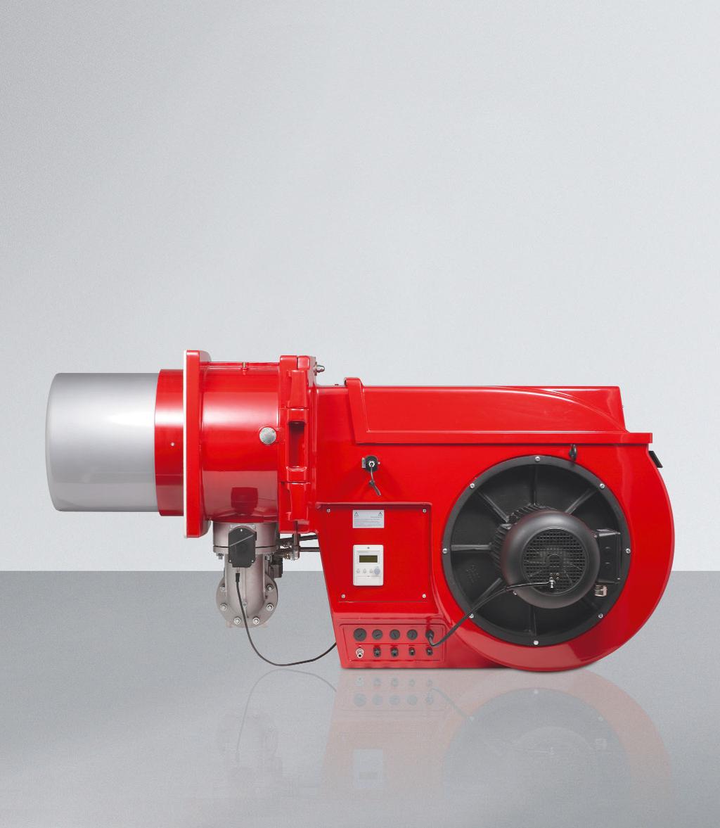
4 Burner motor with inbuilt contactor Air pressure switch Burner housing can be hinged open to the left or to the right Mixing head Flame sensor Digital combustion manager with display and operating unit ABE Stepping motor for diffuser Fan wheel Stepping motor for air damper control Gas valve train with double solenoid valve and shut off device
5 Index of contents Oil burners version Standard Burner selection Scope of delivery / Special equipment Technical data multiflam oil burners version 3LN Burner selection Scope of delivery / Special equipment Technical data Gas burners NR Burner selection Gas valve train sizing Scope of delivery / Special equipment Technical data 5 6 multiflam gas burners version 3LN Burner selection Gas valve train sizing Scope of delivery / Special equipment Technical data Gas burners 1LN Burner selection Gas valve train sizing Scope of delivery / Special equipment Technical data multiflam dual fuel burners version 3LN Burner selection Gas valve train sizing Scope of delivery / Special equipment Technical data Gas burners LN Burner selection Gas valve train sizing Scope of delivery / Special equipment Technical data Dimensions Fuel systems 3 6 Dual fuel burners NR Burner selection Gas valve train sizing Scope of delivery / Special equipment Technical data Pump and preheater station Dual fuel burners 1LN Burner selection Gas valve train sizing Scope of delivery / Special equipment Technical data
6 Weishaupt industrial burners sizes 3 to 7 High capacity and flexible application range Weishaupt industrial burners have been especially designed for industrial applications. The monobloc burners are noteworthy for their large capacity and operational ranges and numerous other interesting details: Flexible application range The burners can be used on heat exchangers such as hot water boilers, steam boilers, air heaters and for certain process applications. As the burners are capable of overcoming high combustion chamber resistances, they are primarily used on high efficiency boilers. Digital combustion management Digital combustion management ensures the simple and safe operation of combustion plant. All important functions, such as fuel and air supply or flame monitoring are controlled with digital precision. Operational functions are optimised, economy is maximised and emissions are minimised. The integral Bus interface enables all necessary information and functions to be relayed to a superordinate control system. Energy saving with speed control and O trim Electrical consumption is definitely a cost factor for large combustion plant. Speed control uses a frequency convertor to match the fan speed to the actual air requirement, allowing for sizeable saving of electrical energy, particularly at partial load. With O trim the flue gases are continuously monitored to ensure the best possible degree of combustion efficiency and thus lower fuel consumption and increased reliability Applicable fuels Light fuel oil (EL) viscosity up to 6 mm /s at C to DIN Medium to heavy fuel oil (S) viscosity up to 5 mm /s at 1 C to DIN Natural Gas E and LL to DVGW work sheet G6/l Liquid Petroleum Gas B/P to DVGW work sheet G6/l Permissible ambient conditions Ambient temperature during operation -1 to + C (oil/dual fuel burners) -15 to + C (gas burners) Humidity: max. % relative humidity, no dewpoint Suitable for use indoors only For plant in unheated areas certain additional measures may be required (please enquire) Use of the burner for applications or in ambient conditions not detailed above is not permitted without prior written agreement of Max Weishaupt GmbH. The service intervals will be reduced in accordance with the more extreme operational conditions. Certification The burners are tested by an independent body and conform to the following standards and EU directives: EN 67 and EN 676 Machinery Directive MD 9/37/EC and 6//EC Electromagnetic Compatibility EMC /1/EC Low Voltage Directive LCV 6/95/EC Gas Appliance Directive GAD 9/396/EEC Pressure Vessel Directive PED 97/3/EC The burners carry the CE and CE-PIN label to 9/396/EU Outstanding service Weishaupt maintains an extensive global sales and service network. Customer service is available every day around the clock. In-house training by Weishaupt ensures the high standard of their service engineers. The most important advantages: Large capacity and application range Stable fan characteristics Good combustion behaviour Burner housing can be hinged open Easy installation, commissioning and service Increased safety provided by nozzle head shut off device with nozzle solenoid Nozzle circulation and precise oil temperature regulation on heavy fuel oil burners Compliance with current emission standards worldwide High turndown ratio (RL, RGL) 6
7 Characteristics of the different variations Version Standard Oil, gas and dual fuel burners for installations without specific NO x requirements. Suitable for Natural Gas, Liquid Petroleum Gas, distillate oil, residual oil, as well as special gases and special oils on request. Type tested burners for Natural Gas and distillate oil in vers. ZM comply with NO x Class 1 to EN 676 and EN 67. Version NR Gas and dual fuel burners with advanced, standard mixing head for installations with gas side NO x requirements. NR means: lower gas side NO x values compared to the standard version. Oil side as standard version. Suitable for Natural Gas, Liquid Petroleum Gas, distillate oil, residual oil. Type tested burners for Natural Gas, Liquid Petroleum Gas and distillate oil in vers. ZM-NR comply with NO x Class (in some cases even NO x Class 3) on the gas side, and NO x Class 1 to EN 676 and EN 67 on the oil side. Version 1LN LowNO x gas and dual fuel burners with special mixing head for installations with gas and oil side NO x requirements. 1LN means: lower NO x values compared to version NR. Suitable for Natural Gas, Liquid Petroleum Gas, distillate oil. Type tested burners for Natural Gas, Liquid Petroleum Gas and distillate oil in vers. ZM-1LN comply with NO x Class 3 on the gas side and NO x Class to EN 676 and EN 67 on the oil side. Version 3LN LowNO x gas and dual fuel burners with multiflam mixing head for installations with extremely low NO x requirements (only for boilers of the three pass or burn-through principle). Extremely low NO x values achieved by fuel division. Suitable for Natural Gas, Liquid Petroleum Gas and distillate oil. Type tested burners for Natural Gas in vers. ZM-3LN comply with NO x Class 3 to EN 676 and EN 67. Comments and notes Standard, NR, 1LN and 3LN burners are fitted with an ignition gas device on the gas side. Project related NO x emission values can be obtained from our NO x commitment list Print No in accordance with the requirements of DIN EN 67 and 676 and Print No for installations to TA-Luft 5 MW and 1. BImSchV 1 MW. Depending on the combustion chamber system, combustion chamber geometry and combustion chamber volume loading different NO x values may be achieved. The conditions listed in relation to measurement tolerances, temperature, pressure humidity etc. should be taken into consideration. Version LN LowNO x gas burners with special mixing head for installations with gas side NO x requirements. LN means: lower gas side NO x value compared to vers. 1LN. Suitable for Natural Gas and Liquid Petroleum Gas. Type tested burners for Natural Gas in vers. ZM-LN (cold air) comply with NO x Class 3 to EN 676 and EN 67. 7

8

9 Oil burners 9
10 Burner selection Oil burners size 3, version Standard [ mbar ] Burner type MS3Z/-A Combustion head M3/ - 19k x 65 Rating kw 675 Rating kg/h, fuel oil M/S 6 17 [ mbar ] Burner type RMS3/-A Combustion head M3/ - 19k x 65 Rating kw 675 Rating kg/h, fuel oil M/S Full Load range 5 3 Fuels Fuel oil S Voltages and frequencies: The burners are equipped as standard for three phase alternating current (D) V, 3~, 5 Hz. Other voltages and frequencies are available on request. Standard burner motor: Insulation Class F, type of protection IP55, Efficiency Class IE Burner type vers. Type test No. Order No. MS3Z/-A 1 33 RMS3/-A ZM 1 35 The stated oil throughputs refer to a calorific value of 11. kwh/kg for fuel oil S. The ratings are dependent on the pressure in the combustion chamber and correspond to the highest values measured on idealised test beds in compliance with EN 67. Capacity graph to EN 67, based on an air temperature of C and an installation altitude of 5 m above sea level. Depending on the altitude of the installation, a reduction of capacity of 1 % for every 1 m above sea level should be taken into account. 1
11 Burner selection Oil burners size, version Standard [ mbar ] Burner type MSZ/1-B MSZ/1-B Combustion head M3/ - x5 M3/ - 175x5 Rating kw Rating kg/h, fuel oil M/S [ mbar ] Burner type RMS/1-B Combustion head M3/ - 19k x 65 Rating kw 75 9 Rating kg/h, fuel oil M/S Full Load range Full Load range [ mbar ] Burner type RMS/-A Combustion head M/ - 17k x 75 Rating kw Rating kg/h, fuel oil M/S 9 3 Burner type Vers. Type test No. Order No. MSZ/1-B 1 RMS/1-B ZM Full Load range RMS/-A ZM 1 5 The stated oil throughputs refer to a calorific value of 11. kwh/kg for fuel oil S. The ratings are dependent on the pressure in the combustion chamber and correspond to the highest values measured on idealised test beds in compliance with EN 67. Fuels Fuel oil S Capacity graph to EN 67, based on an air temperature of C and an installation altitude of 5 m above sea level. Voltages and frequencies: The burners are equipped as standard for three phase alternating current (D) V, 3~, 5 Hz. Other voltages and frequencies are available on request. Standard burner motor: Insulation Class F, type of protection IP55, Efficiency Class IE Depending on the altitude of the installation, a reduction of capacity of 1 % for every 1 m above sea level should be taken into account. Voltages and frequencies: The burners are equipped as standard for three phase alternating current (D) V, 3~, 5 Hz. Other voltages and frequencies are available on request. Standard burner motor: Insulation Class F, type of protection IP55, Efficiency Class IE 11
12 Burner selection Oil burners size 5, version Standard [ mbar ] Burner type L5T/-A Combustion head M5/1-15x5 Rating kw Rating kg/h, fuel oil EL [ mbar ] Burner type RL5/1-B RMS5/1-B Combustion head M/ - 17x75 M/ - 17x75 Rating kw Rating kg/h, fuel oil EL 6 3 fuel oil M/S Full Load range [ mbar ] Burner type RL5/-A RMS5/-A Combustion head M5/ - 9x15 M5/ - 9x15 Rating kw Rating kg/h, fuel oil EL fuel oil M/S Fuel oils Fuel oil EL Fuel oil S Full Load range Voltages and frequencies: The burners are equipped as standard for three phase alternating current (D) V, 3~, 5 Hz. Other voltages and frequencies are available on request (no additional charge). Standard burner motor: Insulation Class F, type of protection IP55, Efficiency Class IE Burner type Vers. Type test No. Order No. L5T/-A - 5G67/ RL5/1-B ZM 5G79/ RMS5/1-B ZM 1 5 RL5/-A ZM 5G79/ RMS5/-A ZM 1 55 The stated oil throughputs refer to a calorific value of kwh/kg for fuel oil EL and 11. kwh/kg for fuel oil S. The ratings are dependent on the pressure in the combustion chamber and correspond to the highest values measured on idealised test beds in compliance with EN 67. Capacity graph to EN 67, based on an air temperature of C and an installation altitude of 5 m above sea level. Depending on the altitude of the installation, a reduction of capacity of 1 % for every 1 m above sea level should be taken into account. 1
13 Burner selection Oil burners size 6 and 7, version Standard [ mbar ] Burner type RL6/-A RMS6/-A Combustion head M6/-35-3 M6/-35-3 Rating kw Rating kg/h fuel oil EL fuel oil S Full Load range [ mbar ] Burner type RL7/1-A RMS7/1-A Combustion head M7/1a-5-9 M7/1a-5-9 Rating kw Rating kg/h fuel oil EL 735 fuel oil S Full Load range 6 1 [ mbar ] Burner type RL7/-A RMS7/-A Combustion head M7/1a-5-9 M7/1a-5-9 Rating kw Rating kg/h fuel oil EL 915 fuel oil S Fuels Fuel oil EL Fuel oil S Full Load range 6 1 Voltages and frequencies: The burners are equipped as standard for three phase alternating current (D) V, 3~, 5 Hz. Other voltages and frequencies are available on request (no additional charge). Standard burner motor: Insulation Class F, type of protection IP55, Efficiency Class IE Burner type Vers. Type test No. Order No. RL6/-A ZM 5G57/ RMS6/-A ZM 1 65 RL7/1-A ZM 5G5/ RMS7/1-A ZM 1 7 RL7/-A ZM 5G59/ RMS7/-A ZM 1 75 The stated oil throughputs refer to a calorific value of kwh/kg for fuel oil EL and 11. kwh/kg for fuel oil S. The ratings are dependent on the pressure in the combustion chamber and correspond to the highest values measured on idealised test beds in compliance with EN 67. Capacity graph to EN 67, based on an air temperature of C and an installation altitude of 5 m above sea level. Depending on the altitude of the installation, a reduction of capacity of 1 % for every 1 m above sea level should be taken into account. 13
14 Scope of delivery/special equipment Oil burners size 3 to 7, version Standard Scope of delivery MS3 MS RMS3 RMS RMS5 RMS6 RMS7 L5 RL5 RL6 RL7 Burner housing, hinge flange, housing cover, Weishaupt burner motor, air intake housing fan wheel, combustion head, ignition unit, ignition cable, ignition electrodes nozzle assembly with oil nozzle/s, combustion manager with operating unit, flame sensor, stepping motors, flange gasket, limit switch on hinge flange, fixing screws Combustion manager W-FM1 Air pressure switch Oil pressure switch in return Oil pressure switch in supply Adjustable regulating sleeve in mixing head Compound controlled regulating sleeve in mixing head Oil pump, fitted Oil preheater, fitted Oil hoses 3 oil solenoid valves, 1 safety shut off valve, three stage nozzle head without shut off device 1 off solenoid valve in supply and return, nozzle head with shut off device (nozzle solenoid on RL and RMS, hydraulically controlled ball valve on MS) 1 off solenoid valve in supply and return, bypass solenoid valve, nozzle head with shut off device (nozzle solenoid) Downward firing version Fitting heated Special equipment Intake flange for connection of air duct Stainless steel oil hoses, heated Magnetic coupling Combustion head extension Media preheater with fittings Speed control O trim W-FM loose to fit into control panel Bus coupling Version TRD hrs/7hrs Scope of delivery Special equipment Additional special equipment see price list or on request. 1
15 Technical data Oil burners size 3 and, version Standard Technical data MS3Z/-A RMS3/-A Burner motor 3~V 1) Type W-D11/1-/K5 W-D11/1-/K5 Nominal load kw.5.5 Electrical consumption at V A Motor pre-fusing (motor in VΔ start) A Speed (5 Hz) rpm 9 9 Fan wheel Colour / ø blau / 6 x 1 blau / 6 x 1 Combustion manager Type LAL.5 W-FM1 Ignition unit Type W-ZG W-ZG Stepping motor Air Type 155/ SQM5 Fuel Type SQM5 Mixing head Type SQM5 Pump fitted Type E7 TA3 Oil preheater Type EVD EVD Oil throughput kg/h 7 7 Heat rating kw 13, 13, Oil solenoid valves 3V 1/ 19 W Type 11 K 3 3V 1/ 19 W Type 1 K V 3/ (supply) W Type 31 H 3 31 H 3 115V 3/ (return) W Type 11 G 3 11 G 3 Oil pressure switches 1 1 bar (return fuel oil EL - 5 bar) Type 1 1 bar (return fuel oil S - 7 bar) Type DSA 6 F1 DSA 6 F1 Oil hoses DN, length /1 /1 (on MS, RMS and RGMS, high pressure metal hoses) /13 /13 Burner weight approx. kg Technical data MSZ/1-B RMS/1-B RMS/-A Burner motor 3~V 1) Type W-D11/17-/5K5 W-D11/17-/5K5 W-D11/17-/7K Nominal load kw Electrical consumption at V A Motor pre-fusing (motor in VΔ start) A 5 Speed (5 Hz) rpm Fan wheel Colour / ø blau / 95 x 1 blau / 95 x 1 blau / 95 x 1 Combustion manager Type LAL.5 W-FM1 W-FM1 Ignition unit Type W-ZG W-ZG W-ZG Stepping motor Air Type SQM1 SQM5 SQM5 Fuel Type SQM5 SQM5 Mixing head Type SQM5 SQM5 Pump fitted Type E7 TA3 TA3 Oil preheater Type EVD EVD ) 3) EVD Oil throughput kg/h Heat rating kw Oil solenoid valves 3V 1/ 19 W Type 11 K 3 3V 1/ (safety v.) W Type 3V 1/ 19 W Type 1K V 3/ (supply) W Type 31 H 3 31 H 3 31 H 3 115V 3/ (return) W Type 11 G 3 11 G 3 11 G 3 Oil pressure switches 1 1 bar (return fuel oil EL - 5 bar) Type 1 1 bar (return fuel oil S - 7 bar) Type DSA 6 F1 DSA 6 F1 DSA 6 F1 Oil hoses DN, length /1 /1 /1 (on MS, RMS and RGMS, high pressure metal hoses) /13 /13 /13 Burner weight approx. kg ) The electric motors comply with the efficiency level IEZ to regulation (EU) No. 6/9. ) Burners above 7 kg/h: Oil preheater WEV. in lieu of EVD, Additional price see Special equipment 3) Burners above 3 kg/h: Oil preheater WEV3 in lieu of WEV., Additional price see Special equipment 15
16 Technical data Oil burners size 5, version Standard Technical data L5T/-A RL5/1-B RL5/-A Burner motor 3~V 1) Type W-D13/1-/1K W-D13/17-/9K W-D13/1-/1K Nominal load kw Electrical consumption at V A 1 Motor pre-fusing (motor in VΔ start) A Speed (5 Hz) rpm Fan wheel Colour / ø blue / 35 x 1.5 blue / 35 x 1.5 blue / 35 x 1.5 Combustion manager Type W-FM1 W-FM1 W-FM1 Ignition unit Type W-ZG W-ZG W-ZG Stepping motor Air Type SQM5 SQM5 SQM5 Fuel Type SQM5 SQM5 Mixing head Type SQM5 SQM5 Pump, fitted Type TAC TAC TC Oil preheater Type Oil throughput kg/h Heat rating kw Oil solenoid valve 3V 1/ 19 W Type 11 K 3 (3 off) 3V 1/ (safety v.) W Type 11 K 6 115V 3/ (supply) W Type 31 H 3 31 H 3 115V 3/ (return) W Type 11 G 3 11 G 3 Oil pressure switches 1 1 bar (return fuel oil EL - 5 bar) Type DSA 6 F1 DSA 6 F1 1 1 bar (return fuel oil S - 7 bar) Type Oil hoses DN, length /13 ( off) 5/13 ( off) 5/13 ( off) Burner weight approx. kg 1 Technical data RMS5/1-B RMS5/-A Burner motor 3~V 1) Type W-D13/17-/9K W-D13/1-/1K Nominal load kw 9 1 Electrical consumption at V A 1 Motor pre-fusing (motor in VΔ start) A 35 5 Speed (5 Hz) rpm 9 9 Fan wheel Colour / ø blue / 35 x 1.5 blue / 35 x 1.5 Combustion manager Type W-FM1 W-FM1 Ignition unit Type W-ZG W-ZG Stepping motor Air Type SQM5 SQM5 Fuel Type SQM5 SQM5 Mixing head Type SQM5 SQM5 Pump, fitted Type TAC TC Oil preheater Type WEV./1 ) WEV3/1 Oil throughput kg/h 3 5 Heat rating kw 13.. Oil solenoid valve 115V 3/ (supply) W Type 31 H 3 31 H 3 115V 3/ (return) W Type 11 G 3 11 G 3 Oil pressure switches 1 1 bar (return fuel oil EL - 5 bar) Type 1 1 bar (return fuel oil S - 7 bar) Type DSA 6 F1 DSA 6 F1 Oil hoses DN, length 5/115 5/115 (on MS, RMS and RGMS, high pressure metal hoses) 5/15 5/15 Burner weight approx. kg 5 1) The electric motors comply with the efficiency level IEZ to regulation (EU) No. 6/9. ) Burners above 3 kg/h: Oil preheater WEV3 in lieu of WEV., Additional price see Special equipment
17 Technical data Oil burners size 6 and 7, version Standard Technical data RL6/-A RMS6/-A Burner motor 3~V 1) Type W-D13/1-/1K W-D13/1-/1K Nominal load kw 1 1 Electrical consumption at V A Motor pre-fusing (motor in VΔ start) A 5 5 Speed (5 Hz) rpm 9 9 Fan wheel Colour / ø blue / 515 x 1 blue / 515 x 1 Combustion manager Type W-FM1 W-FM1 Ignition unit Type W-ZG W-ZG Stepping motor Air Type SQM5 SQM5 Fuel Type SQM5 SQM5 Mixing head Type SQM5 SQM5 Pump fitted Type TC Oil solenoid valves 115V 3/ (supply) W Type 31 H 3 31 H 3 115V 3/ (return) W Type 11 G 3 11 G 3 3V 3/ (bypass) 19 W Type 3 H 736 Oil pressure switches 3 5 bar (supply-1 bar) Type DSA 5 F bar (return fuel oil EL-5 bar) Type DSA 6 F bar (return fuel oil S-7 bar) Type DSA 6 F 1 Oil hoses DN, length 5/13 ( off) /115 (on RMS and RGMS, high pressure metal hoses) /15 Burner weight approx. kg 5 1 ) Technical data RL7/1-A RL7/-A RMS7/1-A RMS7/-A Burner motor 3~V 1) Type W-D/15-/1K W-D/-/K W-D/15-/1K W-D/-/K Nominal load kw 1 1 Electrical consumption at V A Motor pre-fusing (motor in VΔ start) A Speed (5 Hz) rpm Fan wheel Colour / ø green / 53 x 1 blue / 59 x green / 53 x 1 blue / 59 x Combustion manager Type W-FM1 W-FM1 W-FM1 W-FM1 Ignition unit Type W-ZG W-ZG W-ZG W-ZG Stepping motor Air Type SQM5 SQM5 SQM5 SQM5 Fuel Type SQM5 SQM5 SQM5 SQM5 Mixing head Type SQM5 SQM5 SQM5 SQM5 Pump fitted Type TC (up to 6 kg/h) TC (up to 6 kg/h) Type T3C (from 6 kg/h) T3C (from 6 kg/h) Oil solenoid valves 115V 1/ (supply) W Type 31 H 5 31 H 5 31 H 5 31 H 5 115V 1/ (return) W Type 11 G 5 11 G 5 11 G 5 11 G 5 3V 3/ (bypass) 19 W Type 3 H H 736 Oil pressure switch 3 5 bar (supply-1 bar) Type DSA 5 F 1 DSA 5 F bar (return fuel oil EL-5 bar) Type DSA 6 F 1 DSA 6 F bar return fuel oil S-7 bar) Type DSA 6 F 1 DSA 6 F 1 Oil hoses DN, length 5/13 ( off) 5/13 ( off) /115 /115 (on RMS and RGMS, high pressure metal hoses) /15 /15 Burner weight approx. kg ) 31 ) 1) The electric motors comply with the efficiency level IEZ to regulation (EU) No. 6/9. ) Weight without pump and preheater station 17
18 1

19 Gas burners 19
20 Burner selection Gas burners size 5 to 7, version NR [ mbar ] Burner type G5/1-B, vers. ZM-NR Combustion head G/-NR 17x75 Rating kw Nat. Gas 55 LPG Full load range [ mbar ] Burner type G5/-A, vers. ZM-NR Combustion head G5/-NR 9x5 Rating kw Nat. Gas 6 5 LPG Full load range [ mbar ] Burner type G6/-A, vers. ZM-NR Combustion head G6/-NR 35x3 Rating kw Nat. Gas 61 LPG Full load range [ mbar ] Burner type G7/1-B, vers. ZM-NR Combustion head G6/-NR 35x3 Rating kw Nat. Gas 7 LPG Full load range Fuels Nat. Gas LPG The ratings are dependent on the pressure in the combustion chamber and correspond to the highest values measured on idealised test beds in compliance with EN 676. Capacity graph to EN 676, based on an air temperature of C and an installation altitude of 5 m above sea level. Depending on the altitude of the installation, a reduction of capacity of 1 % for every 1 m above sea level should be taken into account. Voltages and frequencies: The burners are equipped as standard for three phase alternating current (D) V, 3~, 5 Hz. Other voltages and frequencies are available on request (no additional charge). Standard burner motor: Insulation Class F, type of protection IP55, Efficiency Class IE Burner Version CE-No. and Valve train Order No. type type test No. G5/1-B ZM-NR CE-5-AQ 71 R 1 1/ R DN DN DN DN G5/-A ZM-NR CE-5-AQ 71 R 1 1/ R DN DN DN DN DN G6/-A ZM-NR CE-5-AQ 7 DN DN DN DN DN G7/1-B ZM-NR CE-5-AQ 73 DN DN DN DN DN
21 Burner selection Gas burners size 7, version NR [ mbar ] Burner type G7/3-A, vers. ZM-NR Combustion head G7/3-NR 5x9 Rating kw Nat. Gas 1 17 LPG Full load range [ mbar ] Burner type G7/-A, vers. ZM-NR Combustion head G7/3-NR 5x9 Rating kw Nat. Gas LPG Full load range Fuels Nat. Gas LPG The ratings are dependent on the pressure in the combustion chamber and correspond to the highest values measured on idealised test beds in compliance with EN 676. Capacity graph to EN 676, based on an air temperature of C and an installation altitude of m above sea level. Burner Version CE-No. and Valve train Order No. type type test No. G7/3-A ZM-NR CE-5-AQ 73 DN DN DN DN DN G7/-A ZM-NR CE-5-AQ 73 DN DN DN DN DN Depending on the altitude of the installation, a reduction of capacity of 1 % for every 1 m above sea level should be taken into account. Voltages and frequencies: The burners are equipped as standard for three phase alternating current (D) V, 3~, 5 Hz. Other voltages and frequencies are available on request (no additional charge). Standard burner motor: Insulation Class F, type of protection IP55, Efficiency Class IE 1
22 Gas valve train sizing Gas burners size 5, version NR Type 5/1-B, version NR Burner Low pressure supply (with FRS) High pressure supply (with HP rating (flow pressure in mbar into shut controller) (flow press. in mbar kw off valve, p e,max = 3 mbar) into double gas valve) Nennweite der Armaturen Nennweite der Armaturen 1½ ½ Nominal diameter of gas butterfly Nominal diameter of gas b/fly Natural Gas E (N) H i = 1,35 kwh/mn 3 ; d =,66; W i = 13,95 kwh/mn Natural Gas LL (N) H i =,3 kwh/mn 3 ; d =,61; W i = 11,9 kwh/mn LPG (F) H i = 5,9 kwh/mn 3 ; d = 1,555; W i =,76 kwh/mn Type 5/-A, version NR Burner Low pressure supply (with FRS) High pressure supply (with HP rating (flow pressure in mbar into shut controller) (flow press. in mbar kw off valve, p e,max = 3 mbar) into double gas valve) Nominal diameter of valve train Nominal diameter of v/train 1½ ½ Nominal diameter of gas butterfly Nominal diameter of gas b/fly Natural Gas E (N) H i = 1,35 kwh/mn 3 ; d =,66; W i = 13,95 kwh/mn Natural Gas LL (N) H i =,3 kwh/mn 3 ; d =,61; W i = 11,9 kwh/mn LPG (F) H i = 5,9 kwh/mn 3 ; d = 1,555; W i =,76 kwh/mn The selection for liquid petroleum gas is calculated for Propane, however it also applies for Butane. The combustion chamber pressure in mbar must be added to the minimum gas pressure required. For low pressure supplies with double solenoid valves (DMV), pressure regulating devices with safety membrane in accordance with EN are used. The maximum permissible supply pressure into the shut off valve for low pressure installations is 3 mbar. For high pressure supplies, high pressure regulators to EN 33 can be selected from the brochure Pressure regulators with safety devices for Weishaupt gas and dual fuel burners. This details high gas pressure sets for supply pressures of up to bar. See burner name plate for maximum connection pressure.
23 Gas valve train sizing Gas burners size 6, version NR Type 6/-A, version NR Burner Low pressure supply (with FRS) High pressure supply (with HP rating (flow pressure in mbar into shut controller) (flow press. in mbar kw off valve, p e,max = 3 mbar) into double gas valve) Nominal diameter of valve train Nominal diameter of v/train Nominal diameter of gas butterfly Nominal diameter of gas b/fly Natural Gas E (N) H i = 1.35 kwh/mn 3 ; d =.66; W i = kwh/mn Natural Gas LL (N) H i =.3 kwh/mn 3 ; d =.61; W i = 11.9 kwh/mn LPG (F) H i = 5.9 kwh/mn 3 ; d = 1.555; W i =,76 kwh/mn The selection for liquid petroleum gas is calculated for Propane, however it also applies for Butane. The combustion chamber pressure in mbar must be added to the minimum gas pressure required. For low pressure supplies with double solenoid valves (DMV), pressure regulating devices with safety membrane in accordance with EN are used. The maximum permissible supply pressure into the shut off valve for low pressure installations is 3 mbar. For high pressure supplies, high pressure regulators to EN 33 can be selected from the brochure Pressure regulators with safety devices for Weishaupt gas and dual fuel burners. This details high gas pressure sets for supply pressures of up to bar. See burner name plate for maximum connection pressure. 3
24 Gas valve train sizing Gas burners size 7, version NR Type 7/1-B, version NR Burner Low pressure supply (with FRS) High pressure supply (with HP rating (flow pressure in mbar into shut controller) (flow press. in mbar kw off valve, p e,max = 3 mbar) into double gas valve) Nominal diameter of valve train Nominal diameter of v/train Nominal diameter of gas butterfly Nominal diameter of gas b/fly Natural Gas E (N) H i = 1.35 kwh/mn 3 ; d =.66; W i = kwh/mn Natural Gas LL (N) H i =.3 kwh/mn 3 ; d =.61; W i = 11.9 kwh/mn LPG (F) H i = 5.9 kwh/mn 3 ; d = 1.555; W i =.76 kwh/mn Type 7/3-A, version NR Burner Low pressure supply (with FRS) High pressure supply (with HP rating (flow pressure in mbar into shut controller) (flow press. in mbar kw off valve, p e,max = 3 mbar) into double gas valve) Nominal diameter of valve train Nominal diameter of v/train Nominal diameter of gas butterfly Nominal diameter of gas b/fly Natural Gas E (N) H i = 1.35 kwh/mn 3 ; d =.66; W i = kwh/mn Natural Gas LL (N) H i =.3 kwh/mn 3 ; d =.61; W i = 11.9 kwh/mn LPG (F) H i = 5.9 kwh/mn 3 ; d = 1.555; W i =.76 kwh/mn The selection for liquid petroleum gas is calculated for Propane, however it also applies for Butane. The combustion chamber pressure in mbar must be added to the minimum gas pressure required. For low pressure supplies with double solenoid valves (DMV), pressure regulating devices with safety membrane in accordance with EN are used. The maximum permissible supply pressure into the shut off valve for low pressure installations is 3 mbar. For high pressure supplies, high pressure regulators to EN 33 can be selected from the brochure Pressure regulators with safety devices for Weishaupt gas and dual fuel burners. This details high gas pressure sets for supply pressures of up to bar. See burner name plate for maximum connection pressure. Type 7/-A, version NR Burner Low pressure supply (with FRS) High pressure supply (with HP rating (flow pressure in mbar into shut controller) (flow press. in mbar kw off valve, p e,max = 3 mbar) into double gas valve) Nominal diameter of valve train Nominal diameter of v/train Nominal diameter of gas butterfly Nominal diameter of gas b/fly Natural Gas E (N) H i = 1.35 kwh/mn 3 ; d =.66; W i = kwh/mn Natural Gas LL (N) H i =.3 kwh/mn 3 ; d =.61; W i = 11.9 kwh/mn LPG (F) H i = 5.9 kwh/mn 3 ; d = 1.555; W i =.76 kwh/mn
25 Scope of delivery/special equipment Gas burners size 5 to 7, version NR Scope of delivery G5 G6 G7 Burner housing, hinge flange, housing cover, Weishaupt burner motor, air regulator housing, fan wheel, combustion head, ignition unit, ignition cable, ignition electrode, combustion manager with operating unit, flame sensor, stepping motors, flange gasket, limit switch on hinge flange, fixing screws Combustion manager W-FM1 Double gas valve, Class A Gas butterfly Ignition gas solenoid valve (Group A) Air pressure switch Gas pressure switch (min.) Compound controlled regulating sleeve in mixing head Stepping motor for Gas /Air compound regulation with W-FM1 Stepping motor for air regulator Stepping motor for gas butterfly valve Stepping motor for regulating sleeve Special equipment Downward firing burner Intake flange for the connection of an air duct Solenoid valve for air pressure switch test for cont. run fan or post-purge Combustion head extension Load controller for W-FM1 Speed control O trim W-FM loo to fit into control panel Bus coupling High gas pressure switch Scope of delivery Special equipment Additional special equipment see price list or on request. 5
26 Technical data Gas burners size 5 to 7, version NR Technical data G5/1-B G5/-A G6/-A Burner motor 3~V 1) Type W-D13/17-/9K W-D13/1-/1K W-D13/1-/1K Nominal load kw Electrical consumption at V A 1 Motor pre-fusing (motor in VΔ start) A Speed (5 Hz) rpm Fan wheel Colour blue blue blue ø 35 x 1 35 x x 1 Combustion manager Type W-FM1 W-FM1 W-FM1 Ignition unit Type W-ZG W-ZG W-ZG Stepping motor Air Type SQM5 SQM5 SQM Mixing head Type SQM5 SQM5 SQM5 Fuel Type SQM5 SQM5 SQM5 Burner weight approx. kg Valve train weight (DMV) R/DN 1 1/ approx. kg Technical data G7/1-B G7/3-A G7/-A Burner motor 3~V 1) Type W-D/15-/1K W-D/-/K W-D/-/K Nominal load kw 1 Electrical consumption at 3 V (V) A Motor pre-fusing (motor in VΔ start) A * Speed (5/55 Hz) rpm Fan wheel Colour blue blue blue ø 59 x 59 x 59 x Combustion manager Type W-FM1 W-FM1 W-FM Ignition unit Type W-ZG W-ZG W-ZG Stepping motor Air Type SQM SQM SQM Mixing head Type SQM5 SQM SQM Fuel Type SQM5 SQM5 SQM5 Burner weight approx. kg 39 Valve train weight (DMV) R/DN 1 1/ approx. kg ) The electric motors comply with the efficiency level IEZ to regulation (EU) No. 6/9. * Operation with 55 Hz frequency converter only. 6
27 Burner selection Gas burners size 5 and 7, version 1LN [ mbar ] Burner type G5/1-B, vers. ZM-1LN Combustion head G/-LN 17x35 Rating kw Nat. Gas 5 3 LPG Full load range [ mbar ] Burner type G7/1-B, vers. ZM-1LN Combustion head G6/-1LN 3x75 Rating kw Nat. Gas 73 LPG Full load range [ mbar ] Burner type G5/-A, vers. ZM-1LN Combustion head G5/-LN 6x Rating kw Nat. Gas 6 9 LPG Full load range 3 5 Burner Version DIN-CERTCO-No. Valve train Order No. type Type test No. G5/1-B ZM-1LN CE-5AQ 71 R 1 1/ 17 5 R DN DN DN DN G5/-A ZM-1LN CE-5AQ 71 R 1 1/ R DN DN DN DN DN G7/1-B ZM-1LN CE-5AQ 73 DN DN DN DN DN G7/-A ZM-1LN CE-5AQ 73 DN DN DN DN DN [ mbar ] Burner type G7/-A, vers. ZM-1LN Combustion head G7/-1LN 365x5 Rating kw Nat. Gas 1 1 LPG Full load range Fuels Capacity with Comb. head Open Comb. head Closed Nat. Gas LPG The ratings are dependent on the pressure in the combustion chamber and correspond to the highest values measured on idealised test beds in compliance with EN 676. Capacity graph to EN 676, based on an air temperature of C and an installation altitude of m above sea level. Depending on the altitude of the installation, a reduction of capacity of 1 % for every 1 m above sea level should be taken into account. Voltages and frequencies: The burners are equipped as standard for three phase alternating current (D) V, 3~, 5 Hz. Other voltages and frequencies are available on request (no additional charge). Standard burner motor: Insulation Class F, type of protection IP55, Efficiency Class IE 7
28 Gas valve train sizing Gas burners size 5, version 1LN Type 5/1-B, version 1LN Burner Low pressure supply (with FRS) High pressure supply (with HP rating (flow pressure in mbar into shut controller) (flow press. in mbar kw off valve, p e,max = 3 mbar) into double gas valve) Nominal diameter of valve train Nominal diameter of v/train 1½ ½ Nominal diameter of gas butterfly Nominal diameter of gas b/fly Natural Gas E (N) H i = 1.35 kwh/mn 3 ; d =.66; W i = kwh/mn Natural Gas LL (N) H i =.3 kwh/mn 3 ; d =.61; W i = 11.9 kwh/mn LPG (F) H i = 5.9 kwh/mn 3 ; d = 1.555; W i =.76 kwh/mn Type 5/-A, version 1LN Burner Low pressure supply (with FRS) High pressure supply (with HP rating (flow pressure in mbar into shut controller) (flow press. in mbar kw off valve, p e,max = 3 mbar) into double gas valve) Nominal diameter of valve train Nominal diameter of v/train 1½ ½ Nominal diameter of gas butterfly Nominal diameter of gas b/fly Natural Gas E (N) H i = 1.35 kwh/mn 3 ; d =.66; W i = kwh/mn Natural Gas LL (N) H i =.3 kwh/mn 3 ; d =.61; W i = 11.9 kwh/mn LPG (F) H i = 5.9 kwh/mn 3 ; d = 1.555; W i =.76 kwh/mn The selection for liquid petroleum gas is calculated for Propane, however it also applies for Butane. The combustion chamber pressure in mbar must be added to the minimum gas pressure required. For low pressure supplies with double solenoid valves (DMV), pressure regulating devices with safety membrane in accordance with EN are used. The maximum permissible supply pressure into the shut off valve for low pressure installations is 3 mbar. For high pressure supplies, high pressure regulators to EN 33 can be selected from the brochure Pressure regulators with safety devices for Weishaupt gas and dual fuel burners. This details high gas pressure sets for supply pressures of up to bar. See burner name plate for maximum connection pressure.
29 Gas valve train sizing Gas burner size 7, version 1LN Type 7/1-B, version 1LN Burner Low pressure supply (with FRS) High pressure supply (with HP rating (flow pressure in mbar into shut controller) (flow press. in mbar kw off valve, p e,max = 3 mbar) into double gas valve) Nominal diameter of valve train Nominal diameter of v/train Nominal diameter of gas butterfly Nominal diameter of gas b/fly Natural Gas E (N) H i = 1.35 kwh/mn 3 ; d =.66; W i = kwh/mn Natural Gas LL (N) H i =.3 kwh/mn 3 ; d =.61; W i = 11.9 kwh/mn LPG (F) H i = 5.9 kwh/mn 3 ; d = 1.555; W i =.76 kwh/mn Type 7/-A, version 1LN Burner Low pressure supply (with FRS) High pressure supply (with HP rating (flow pressure in mbar into shut controller) (flow press. in mbar kw off valve, p e,max = 3 mbar) into double gas valve) Nominal diameter of valve train Nominal diameter of v/train Nominal diameter of gas butterfly Nominal diameter of gas b/fly Natural Gas E (N) H i = 1.35 kwh/mn 3 ; d =.66; W i = kwh/mn Natural Gas LL (N) H i =.3 kwh/mn 3 ; d =.61; W i = 11.9 kwh/mn LPG (F) H i = 5.9 kwh/mn 3 ; d = 1.555; W i =.76 kwh/mn The selection for liquid petroleum gas is calculated for Propane, however it also applies for Butane. The combustion chamber pressure in mbar must be added to the minimum gas pressure required. For low pressure supplies with double solenoid valves (DMV), pressure regulating devices with safety membrane in accordance with EN are used. The maximum permissible supply pressure into the shut off valve for low pressure installations is 3 mbar. For high pressure supplies, high pressure regulators to EN 33 can be selected from the brochure Pressure regulators with safety devices for Weishaupt gas and dual fuel burners. This details high gas pressure sets for supply pressures of up to bar. See burner name plate for maximum connection pressure. 9
30 Scope of delivery/special equipment Gas burners size 5 and 7, version 1LN Scope of delivery G5 G7 Burner housing, hinge flange, housing cover, Weishaupt burner motor, air regulator housing, fan wheel, combustion head, ignition unit, ignition cable, ignition electrode, combustion manager with operating unit, flame sensor, stepping motors, flange gasket, limit switch on hinge flange, fixing screws Combustion manager W-FM1 Double gas valve, Class A Gas butterfly valve Gas ignition unit Air pressure switch Low gas pressure switch Adjustable regulating sleeve in mixing head Stepping motor for Gas/Air compound regulation with W-FM1 Stepping motor for air regulator Stepping motor for gas butterfly valve Special equipment Downward firing burner Intake flange for the connection of an air duct Solenoid valve for air pressure switch test for cont. run fan or post-purge Combustion head extension Load controller for W-FM1 Speed control O trim W-FM loose to fit into control panel Bus coupling High gas pressure switch Scope of delivery Special equipment Additional special equipment see price list or on request. 3
31 Technical data Gas burners size 5 and 7, version 1LN Technical data G5/1-B G5/-A G7/1-B G7/-A Burner motor 3~V 1) Type W-D13/17-/9K W-D13/1-/1K W-D/-/1K W-D/-/K Nominal load kw Electrical consumption at V A 1 3,5 3 Motor pre-fusing (motor in VΔ start) A Speed (5 Hz) rpm Fan wheel Colour blue blue blue blue ø 35 x 1 35 x 1 59 x 59 x Combustion manager Type W-FM1 W-FM1 W-FM1 W-FM1 Ignition unit Type W-ZG W-ZG W-ZG W-ZG Stepping motor Air Type SQM5 SQM5 SQM SQM Fuel Type SQM5 SQM5 SQM5 SQM5 Burner weight approx. kg Valve train weight (DMV) R/DN 1 1/ approx. kg ) The electric motors comply with the efficiency level IEZ to regulation (EU) No. 6/9. 31
32 Burner selection Gas burners size 5, version LN [ mbar ] Burner type G5/1-B, vers. ZM-LN Combustion head G/-3a-1 x 6 Rating kw Full load range [ mbar ] Burner type G5/-A, vers. ZM-LN Combustion head G5/-3a-5 x 9 Rating kw Full load range 3 5 Fuels Capacity with Comb. head Open Comb. head Closed Nat. Gas Voltages and frequencies: The burners are equipped as standard for three phase alternating current (D) V, 3~, 5 Hz. Other voltages and frequencies are available on request (no additional charge). Standard burner motor: Insulation Class F, type of protection IP55, Efficiency Class IE Burner Version DIN-CERTCO-No. Valve train Order No. type Type test No. G5/1-B ZM-LN CE-5AQ 71 R 1 1/ R DN DN DN DN G5/-A ZM-LN CE-5AQ 71 R 1 1/ R DN DN DN DN DN The ratings are dependent on the pressure in the combustion chamber and correspond to the highest values measured on idealised test beds in compliance with EN 676. Capacity graph to EN 676, based on an air temperature of C and an installation altitude of 5 m above sea level. Depending on the altitude of the installation, a reduction of capacity of 1 % for every 1 m above sea level should be taken into account. 3
33 Burner selection Gas burners size 6 and 7, version LN [ mbar ] Burner type G6/-A, vers. ZM-LN Combustion head G6/-3a-3 x 1 Rating kw Full load range [ mbar ] Burner type G7/1-B, vers. ZM-LN Combustion head G6/-3a-3 x 1 Rating kw Full load range [ mbar ] Burner type G7/-A, vers. ZM-LN Combustion head G7/-3a-355 x 1 Rating kw Full load range Burner Version DIN-CERTCO-No. Valve train Order No. type Type test No. G6/-A ZM-LN CE-5AQ 7 R DN DN DN DN DN G7/1-B ZM-LN CE-5AQ 73 DN DN DN DN DN G7/-A ZM-LN CE-5AQ 73 DN DN DN DN DN Fuels Capacity with Comb. head Open Comb. head Closed Nat. Gas Voltages and frequencies: The burners are equipped as standard for three phase alternating current (D) V, 3~, 5 Hz. Other voltages and frequencies are available on request (no additional charge). Standard burner motor: Insulation Class F, type of protection IP55, Efficiency Class IE The ratings are dependent on the pressure in the combustion chamber and correspond to the highest values measured on idealised test beds in compliance with EN 676. Capacity graph to EN 676, based on an air temperature of C and an installation altitude of m above sea level. Depending on the altitude of the installation, a reduction of capacity of 1 % for every 1 m above sea level should be taken into account. 33
34 Gas valve train sizing Gas burners size 5, version LN Type 5/1-B, version LN Burner Low pressure supply (with FRS) High pressure supply (with HP rating (flow pressure in mbar into shut controller) (flow press. in mbar kw off valve, p e,max = 3 mbar) into double gas valve) Nominal diameter of valve train Nominal diameter of v/train 1½ ½ Nominal diameter of gas butterfly Nominal diameter of gas b/fly Natural Gas E (N) H i = 1.35 kwh/mn 3 ; d =.66; W i = kwh/mn Natural Gas LL (N) H i =.3 kwh/mn 3 ; d =.61; W i = 11.9 kwh/mn Type 5/-A, version LN Burner Low pressure supply (with FRS) High pressure supply (with HP rating (flow pressure in mbar into shut controller) (flow press. in mbar kw off valve, p e,max = 3 mbar) into double gas valve) Nominal diameter of valve train Nominal diameter of v/train Nominal diameter of gas butterfly Nominal diameter of gas b/fly Natural Gas E (N) H i = 1.35 kwh/mn 3 ; d =.66; W i = kwh/mn Natural Gas LL (N) H i =.3 kwh/mn 3 ; d =.61; W i = 11.9 kwh/mn The combustion chamber pressure in mbar must be added to the minimum gas pressure required. For low pressure supplies with double solenoid valves (DMV), pressure regulating devices with safety membrane in accordance with EN are used. The maximum permissible supply pressure into the shut off valve for low pressure installations is 3 mbar. For high pressure supplies, high pressure regulators to EN 33 can be selected from the brochure Pressure regulators with safety devices for Weishaupt gas and dual fuel burners. This details high gas pressure sets for supply pressures of up to bar. See burner name plate for maximum connection pressure. 3
35 Gas valve train sizing Gas burners size 6 and 7, version LN Type 6/-A, version LN Burner Low pressure supply (with FRS) High pressure supply (with HP rating (flow pressure in mbar into shut controller) (flow press. in mbar kw off valve, p e,max = 3 mbar) into double gas valve) Nominal diameter of valve train Nominal diameter of v/train Nominal diameter of gas butterfly Nominal diameter of gas b/fly Natural Gas E (N) H i = 1.35 kwh/mn 3 ; d =.66; W i = kwh/mn Natural Gas LL (N) H i =.3 kwh/mn 3 ; d =.61; W i = 11.9 kwh/mn Type 7/1-B, version LN Burner Low pressure supply (with FRS) High pressure supply (with HP rating (flow pressure in mbar into shut controller) (flow press. in mbar kw off valve, p e,max = 3 mbar) into double gas valve) Nominal diameter of valve train Nominal diameter of v/train Nominal diameter of gas butterfly Nominal diameter of gas b/fly Natural Gas E (N) H i = 1.35 kwh/mn 3 ; d =.66; W i = kwh/mn Natural Gas LL (N) H i =.3 kwh/mn 3 ; d =.61; W i = 11.9 kwh/mn Type 7/-A, Version LN Burner Low pressure supply (with FRS) High pressure supply (with HP rating (flow pressure in mbar into shut controller) (flow press. in mbar kw off valve, p e,max = 3 mbar) into double gas valve) Nominal diameter of valve train Nominal diameter of v/train Nominal diameter of gas butterfly Nominal diameter of gas b/fly Natural Gas E (N) H i = 1.35 kwh/mn 3 ; d =.66; W i = kwh/mn Natural Gas LL (N) H i =.3 kwh/mn 3 ; d =.61; W i = 11.9 kwh/mn The combustion chamber pressure in mbar must be added to the minimum gas pressure required. For low pressure supplies with double solenoid valves (DMV), pressure regulating devices with safety membrane in accordance with EN are used. The maximum permissible supply pressure into the shut off valve for low pressure installations is 3 mbar. For high pressure supplies, high pressure regulators to EN 33 can be selected from the brochure Pressure regulators with safety devices for Weishaupt gas and dual fuel burners. This details high gas pressure sets for supply pressures of up to bar. See burner name plate for maximum connection pressure. 35
36 Scope of delivery/special equipment Gas burners size 5 to 7, version LN Scope of delivery G5 G6 G7 Burner housing, hinge flange, housing cover, Weishaupt burner motor, air regulator housing, fan wheel, combustion head, ignition unit, ignition cable, ignition electrodes, combustion manager with operating unit, flame sensor, stepping motors, flange gasket, limit switch on hinge flange, fixing screws Combustion manager W-FM1 Double gas valve, Class A Gas butterfly valve Air pressure switch Low gas pressure switch Adjustable flame tube in mixing head Stepping motor for Gas /Air compound regulation with W-FM1 Stepping motor for air regulator Stepping motor for gas butterfly valve Special equipment Downward firing burner Intake flange for the connection of an air duct Combustion head extension Load controller W-FM1 Speed control O trim W-FM loose to fit into control panel Bus coupling High gas pressure switch Scope of delivery Special equipment Additional special equipment see price list or on request. 36
37 Technical data Gas burners size 5 to 7, version LN Technical data G5/1-B G5/-A Burner motor 3~V 1) Type W-D13/17-/9K W-D13/1-/1K Nominal load kw 9 1 Electrical consumption at 3 V (V) A 1 Motor pre-fusing (motor in VΔ start) A 35 5 Speed (5 Hz) rpm 9 9 Fan wheel Colour blue blue ø 35 x 1 35 x 1 Combustion manager Type W-FM1 W-FM1 Ignition unit Type W-ZG W-ZG Stepping motor Air Type SQM5 SQM5 Fuel Type SQM5 SQM5 Burner weight approx. kg Valve train weight (DMV) R/DN 1 1/ approx. kg Technical data G6/-A G7/1-B G7/-A Burner motor 3~V 1) Type W-D13/1-/1K W-D/15-/1K W-D/-/K Nominal load kw 1 1 Electrical consumption at 3 V (V) A 6 3 Motor pre-fusing (motor in VΔ start) A Speed (5 Hz) rpm Fan wheel Colour blue blue blue ø 515 x 1 59 x 59 x Combustion manager Type W-FM1 W-FM1 W-FM1 Ignition unit Type W-ZG W-ZG W-ZG Stepping motor Air Type SQM SQM SQM Fuel Type SQM5 SQM5 SQM5 Burner weight approx. kg Valve train weight (DMV) R/DN 1 1/ approx. kg ) The electric motors comply with the efficiency level IEZ to regulation (EU) No. 6/9. 37
38 3
39 Dual fuel burners 39
40 Burner selection Dual fuel burners size 3, version NR [ mbar ] Burner type RGL3/-A, RGMS3/-A, vers. ZM-NR vers. ZM-NR Combustion head G3/-NR 19x65 G3/-NR 19x65 Rating kw N/F Gas Rating kg/h Fuel oil EL 193 Fuel oil S Full load range 15 5 Burner Version DIN-CERTCO-No. Valve train Order No. type Type test No. RGL3/-A ZM-NR CE-5-AP 5 R 1 1/ G311/ M R DN DN DN DN RGMS3/-A ZM-NR CE-5-AP 5 R 1 1/ R DN DN DN DN Fuels Capacity withi Fuel oil EL Fuel oil S Nat. Gas LPG The stated oil throughputs refer to a calorific value of kwh/kg for fuel oil EL and 11. kwh/kg for fuel oil S. The ratings are dependent on the pressure in the combustion chamber and correspond to the highest values measured on idealised test beds in compliance with EN 676 and EN 67. Capacity graph to EN 676 and EN 67, based on an air temperature of C and an installation altitude of 5 m above sea level. Depending on the altitude of the installation, a reduction of capacity of 1 % for every 1 m above sea level should be taken into account. Voltages and frequencies: The burners are equipped as standard for three phase alternating current (D) V, 3~, 5 Hz. Other voltages and frequencies are available on request (no additional charge). Standard burner motor: Insulation Class F, type of protection IP55, Efficiency Class IE
41 Burner selection Dual fuel burners size, version NR [ mbar ] Burner type RGL/1-B, RGMS/1-B, vers. ZM-NR vers. ZM-NR Combustion head G3/-NR 19x5 G3/-NR 19x5 Rating kw N/F Gas Rating kg/h Fuel oil EL 5 7 Fuel oil S 7 [ mbar ] Burner type RGL/-A, RGMS/-A, vers. ZM-NR vers. ZM-NR Combustion head G/-NR 17x75 G/-NR 17x75 Rating kw N/F Gas Rating kg/h Fuel oil EL 55 9 Fuel oil S Full load range Full load range Burner Version DIN-CERTCO-No. Valve train Order No. type Type test No. RGMS/1-B ZM-NR CE-5-AQ 7 R 1 1/ R DN DN 19 5 DN DN RGL/-A ZM-NR CE-5-AQ 7 R 1 1/ G567/5M R DN DN DN DN RGMS/-A ZM-NR CE-5-AQ 7 R 1 1/ R DN DN DN DN Fuels Capacity withi Fuel oil EL Fuel oil S Nat. Gas LPG The stated oil throughputs refer to a calorific value of kwh/kg for fuel oil EL and 11. kwh/kg for fuel oil S. The ratings are dependent on the pressure in the combustion chamber and correspond to the highest values measured on idealised test beds in compliance with EN 676 and EN 67. Capacity graph to EN 676 and EN 67, based on an air temperature of C and an installation altitude of 5 m above sea level. Depending on the altitude of the installation, a reduction of capacity of 1 % for every 1 m above sea level should be taken into account. Voltages and frequencies: The burners are equipped as standard for three phase alternating current (D) V, 3~, 5 Hz. Other voltages and frequencies are available on request (no additional charge). Standard burner motor: Insulation Class F, type of protection IP55, Efficiency Class IE 1
42 Burner selection Dual fuel burners size 5, version NR [ mbar ] Burner type RGL5/1-B, RGMS5/1-B, vers. ZM-NR vers. ZM-NR Combustion head G/-NR 17x75 G/-NR 17x75 Rating kw N/F Gas Rating kg/h Fuel oil EL Fuel oil S Full load range [ mbar ] Burner type RGL5/-A, RGMS5/-A, vers. ZM-NR vers. ZM-NR Combustion head G5/-NR 9x15 G5/-NR 9x15 Rating kw Nat. Gas LPG 5 5 Rating kg/h Fuel oil EL Fuel oil S Full load range Burner Version DIN-CERTCO-No. Valve train Order No. type Type test No. RGL5/1-B ZM-NR CE-5-AQ 71 R 1 1/ G535/5M R DN DN DN DN RGMS5/1-B ZM-NR CE-5-AQ 71 R 1 1/ R DN DN DN DN RGL5/-A ZM-NR CE-5-AQ 71 R 1 1/ G535/5M R DN DN DN DN DN RGMS5/-A ZM-NR CE-5-AQ 71 R 1 1/ R DN DN DN DN DN Fuels Capacity withi Fuel oil EL Fuel oil S Nat. Gas LPG The stated oil throughputs refer to a calorific value of kwh/kg for fuel oil EL and 11. kwh/kg for fuel oil S. The ratings are dependent on the pressure in the combustion chamber and correspond to the highest values measured on idealised test beds in compliance with EN 676 and EN 67. Capacity graph to EN 676 and EN 67, based on an air temperature of C and an installation altitude of 5 m above sea level. Depending on the altitude of the installation, a reduction of capacity of 1 % for every 1 m above sea level should be taken into account. Voltages and frequencies: The burners are equipped as standard for three phase alternating current (D) V, 3~, 5 Hz. Other voltages and frequencies are available on request (no additional charge). Standard burner motor: Insulation Class F, type of protection IP55, Efficiency Class IE
43 Burner selection Dual fuel burners size 6 and 7, version NR [ mbar ] Burner type RGL6/-A, RGMS6/-A vers. ZM-NR vers. ZM-NR Combustion head G6/-NR 35x3 G6/-NR 35x3 Rating kw N/F-Gas Rating kg/h Fuel oil EL Fuel oil S Full load range [ mbar ] Burner type RGL7/1-B, RGMS7/1-B, vers. ZM-NR vers. ZM-NR Combustion head G6/-NR 35x3 G6/-NR 35x3 Rating kw N/F-Gas 7 7 Rating kg/h Fuel oil EL 1 61 Fuel oil S Full load range Burner Version DIN-CERTCO-No. Valve train Order No. type Type test No. RGL6/-A ZM-NR CE-5-AQ 7 DN G51/5M DN DN DN DN 15 * 1 65 RGMS6/-A ZM-NR CE-5-AQ 7 DN DN DN DN DN 15 * RGL7/1-B ZM-NR CE-5-AQ 73 DN G519/5M DN DN DN DN RGMS7/1-B ZM-NR CE-5-AQ 73 DN DN DN DN DN Fuels Capacity withi Fuel oil EL Fuel oil S Nat. Gas LPG The stated oil throughputs refer to a calorific value of kwh/kg for fuel oil EL and 11. kwh/kg for fuel oil S. The ratings are dependent on the pressure in the combustion chamber and correspond to the highest values measured on idealised test beds in compliance with EN 676 and EN 67. Capacity graph to EN 676 and EN 67, based on an air temperature of C and an installation altitude of 5 m above sea level. Depending on the altitude of the installation, a reduction of capacity of 1 % for every 1 m above sea level should be taken into account. Voltages and frequencies: The burners are equipped as standard for three phase alternating current (D) V, 3~, 5 Hz. Other voltages and frequencies are available on request (no additional charge). Standard burner motor: Insulation Class F, type of protection IP55, Efficiency Class IE 3
44 Burner selection Dual fuel burners size 7, version NR [ mbar ] Burner type RGL7/3-A RGMS7/3-A vers. ZM-NR vers. ZM-NR Combustion head G7/3-A-NR 5x9 G7/3-A-NR 5x9 Rating kw Nat. Gas LPG Rating kg/h Fuel oil EL Fuel oil S Full load range [ mbar ] Burner type RGL7/-A, RGMS7/-A vers. ZM-NR vers. ZM-NR Combustion head G7/3-A-NR 5x9 G7/3-A-NR 5x9 Rating kw Nat. Gas LPG Rating kg/h Fuel oil EL Fuel oil S Full load range Burner Version DIN-CERTCO-No. Valve train Order No. type Type test No. RGL7/3-A ZM-NR CE-5-AQ 73 DN G519/5M DN DN DN DN RGMS7/3-A ZM-NR CE-5-AQ 73 DN DN DN DN DN RGL7/-A ZM-NR CE-5-AQ 73 DN G519/5M DN DN DN DN RGMS7/-A ZM-NR CE-5-AQ 73 DN DN DN DN DN Fuels Capacity withi Fuel oil EL Fuel oil S Nat. Gas LPG The stated oil throughputs refer to a calorific value of kwh/kg for fuel oil EL and 11. kwh/kg for fuel oil S. The ratings are dependent on the pressure in the combustion chamber and correspond to the highest values measured on idealised test beds in compliance with EN 676 and EN 67. Capacity graph to EN 676 and EN 67, based on an air temperature of C and an installation altitude of m above sea level. Depending on the altitude of the installation, a reduction of capacity of 1 % for every 1 m above sea level should be taken into account. Voltages and frequencies: The burners are equipped as standard for three phase alternating current (D) V, 3~, 5 Hz. Other voltages and frequencies are available on request (no additional charge). Standard burner motor: Insulation Class F, type of protection IP55, Efficiency Class IE
45 Gas valve train sizing Dual fuel burners size 3 and, version NR Type 3/-A, version NR Burner Low pressure supply (with FRS) High pressure supply (with HP rating (flow pressure in mbar into shut controller) (flow press. in mbar kw off valve, p e,max = 3 mbar) into double gas valve) Nominal diameter of valve train Nominal diameter of v/train 1½ ½ Nominal diameter of gas butterfly Nominal diameter of gas b/fly Natural Gas E (N) H i = 1.35 kwh/mn 3 ;d =.66;W i = kwh/mn Natural Gas LL (N) H i =.3 kwh/mn 3 ;d =.61;W i = 11.9 kwh/mn LPG (F) H i = 5.9 kwh/mn 3 ; d = 1.555; W i =.76 kwh/mn Type /1-B, version NR Burner Low pressure supply (with FRS) High pressure supply (with HP rating (flow pressure in mbar into shut controller) (flow press. in mbar kw off valve, p e,max = 3 mbar) into double gas valve) Nominal diameter of valve train Nominal diameter of v/train 1½ ½ Nominal diameter of gas butterfly Nominal diameter of gas b/fly Natural Gas E (N) H i = 1.35 kwh/mn 3 ;d =.66;W i = kwh/mn Natural Gas LL (N) H i =.3 kwh/mn 3 ;d =.61;W i = 11.9 kwh/mn LPG (F) H i = 5.9 kwh/mn 3 ; d = 1.555; W i =.76 kwh/mn Type /-A, version NR Burner Low pressure supply (with FRS) High pressure supply (with HP rating (flow pressure in mbar into shut controller) (flow press. in mbar kw off valve, p e,max = 3 mbar) into double gas valve) Nominal diameter of valve train Nominal diameter of v/train 1½ ½ Nominal diameter of gas butterfly Nominal diameter of gas b/fly Natural Gas E (N) H i = 1.35 kwh/mn 3 ;d =.66;W i = kwh/mn Natural Gas LL (N) H i =.3 kwh/mn 3 ;d =.61;W i = 11.9 kwh/mn LPG (F) H i = 5.9 kwh/mn 3 ; d = 1.555; W i =.76 kwh/mn The selection for liquid petroleum gas is calculated for Propane, however it also applies for Butane. The combustion chamber pressure in mbar must be added to the minimum gas pressure required. For low pressure supplies with double solenoid valves (DMV), pressure regulating devices with safety membrane in accordance with EN are used. The maximum permissible supply pressure into the shut off valve for low pressure installations is 3 mbar. For high pressure supplies, high pressure regulators to EN 33 can be selected from the brochure Pressure regulators with safety devices for Weishaupt gas and dual fuel burners. This details high gas pressure sets for supply pressures of up to bar. See burner name plate for maximum connection pressure. 5
46 Gas valve train sizing Dual fuel burners size 5, version NR Type 5/1-B, version NR Burner Low pressure supply (with FRS) High pressure supply (with HP rating (flow pressure in mbar into shut controller) (flow press. in mbar kw off valve, p e,max = 3 mbar) into double gas valve) Nominal diameter of valve train Nominal diameter of v/train 1½ ½ Nominal diameter of gas butterfly Nominal diameter of gas b/fly Natural Gas E (N) H i = 1.35 kwh/mn 3 ;d =.66;W i = kwh/mn Natural Gas LL (N) H i =.3 kwh/mn 3 ;d =.61;W i = 11.9 kwh/mn LPG (F) H i = 5.9 kwh/mn 3 ; d = 1.555; W i =.76 kwh/mn Type 5/-A, version NR Burner Low pressure supply (with FRS) High pressure supply (with HP rating (flow pressure in mbar into shut controller) (flow press. in mbar kw off valve, p e,max = 3 mbar) into double gas valve) Nominal diameter of valve train Nominal diameter of v/train 1½ ½ Nominal diameter of gas butterfly Nominal diameter of gas b/fly Natural Gas E (N) H i = 1.35 kwh/mn 3 ;d =.66;W i = kwh/mn Natural Gas LL (N) H i =.3 kwh/mn 3 ;d =.61;W i = 11.9 kwh/mn LPG (F) H i = 5.9 kwh/mn 3 ; d = 1.555; W i =.76 kwh/mn The selection for liquid petroleum gas is calculated for Propane, however it also applies for Butane. The combustion chamber pressure in mbar must be added to the minimum gas pressure required. For low pressure supplies with double solenoid valves (DMV), pressure regulating devices with safety membrane in accordance with EN are used. The maximum permissible supply pressure into the shut off valve for low pressure installations is 3 mbar. For high pressure supplies, high pressure regulators to EN 33 can be selected from the brochure Pressure regulators with safety devices for Weishaupt gas and dual fuel burners. This details high gas pressure sets for supply pressures of up to bar. See burner name plate for maximum connection pressure. 6
47 Gas valve train sizing Dual duel burners size 6, version NR Type 6/-A, version NR Burner Low pressure supply (with FRS) High pressure supply (with HP rating (flow pressure in mbar into shut controller) (flow press. in mbar kw off valve, p e,max = 3 mbar) into double gas valve) Nominal diameter of valve train Nominal diameter of v/train Nominal diameter of gas butterfly Nominal diameter of gas b/fly Natural Gas E (N) H i = 1.35 kwh/mn 3 ;d =.66;W i = kwh/mn Natural Gas LL (N) H i =.3 kwh/mn 3 ;d =.61;W i = 11.9 kwh/mn LPG (F) H i = 5.9 kwh/mn 3 ; d = 1.555; W i =.76 kwh/mn The selection for liquid petroleum gas is calculated for Propane, however it also applies for Butane. The combustion chamber pressure in mbar must be added to the minimum gas pressure required. For low pressure supplies with double solenoid valves (DMV), pressure regulating devices with safety membrane in accordance with EN are used. The maximum permissible supply pressure into the shut off valve for low pressure installations is 3 mbar. For high pressure supplies, high pressure regulators to EN 33 can be selected from the brochure Pressure regulators with safety devices for Weishaupt gas and dual fuel burners. This details high gas pressure sets for supply pressures of up to bar. See burner name plate for maximum connection pressure. 7
48 Gas valve train sizing Dual fuel burners size 7, version NR Type 7/1-B, version NR Burner Low pressure supply (with FRS) High pressure supply (with HP rating (flow pressure in mbar into shut controller) (flow press. in mbar kw off valve, p e,max = 3 mbar) into double gas valve) Nominal diameter of valve train Nominal diameter of v/train Nominal diameter of gas butterfly Nominal diameter of gas b/fly Natural Gas E (N) H i = 1.35 kwh/mn 3 ;d =.66;W i = kwh/mn Natural Gas LL (N) H i =.3 kwh/mn 3 ;d =.61;W i = 11.9 kwh/mn LPG (F) H i = 5.9 kwh/mn 3 ; d = 1.555; W i =.76 kwh/mn Type 7/3-A, version NR Burner Low pressure supply (with FRS) High pressure supply (with HP rating (flow pressure in mbar into shut controller) (flow press. in mbar kw off valve, p e,max = 3 mbar) into double gas valve) Nominal diameter of valve train Nominal diameter of v/train Nominal diameter of gas butterfly Nominal diameter of gas b/fly Natural Gas E (N) H i = 1.35 kwh/mn 3 ;d =.66;W i = kwh/mn Natural Gas LL (N) H i =.3 kwh/mn 3 ;d =.61;W i = 11.9 kwh/mn LPG (F) H i = 5.9 kwh/mn 3 ; d = 1.555; W i =.76 kwh/mn The selection for liquid petroleum gas is calculated for Propane, however it also applies for Butane. The combustion chamber pressure in mbar must be added to the minimum gas pressure required. For low pressure supplies with double solenoid valves (DMV), pressure regulating devices with safety membrane in accordance with EN are used. The maximum permissible supply pressure into the shut off valve for low pressure installations is 3 mbar. For high pressure supplies, high pressure regulators to EN 33 can be selected from the brochure Pressure regulators with safety devices for Weishaupt gas and dual fuel burners. This details high gas pressure sets for supply pressures of up to bar. See burner name plate for maximum connection pressure.
49 Gas valve train sizing Dual fuel burners size 7, version NR Type 7/-A, version NR Burner Low pressure supply (with FRS) High pressure supply (with HP rating (flow pressure in mbar into shut controller) (flow press. in mbar kw off valve, p e,max = 3 mbar) into double gas valve) Nominal diameter of valve train Nominal diameter of v/train Nominal diameter of gas butterfly Nominal diameter of gas b/fly Natural Gas E (N) H i = 1.35 kwh/mn 3 ;d =.66;W i = kwh/mn Natural Gas LL (N) H i =.3 kwh/mn 3 ;d =.61;W i = 11.9 kwh/mn LPG (F) H i = 5.9 kwh/mn 3 ; d = 1.555; W i =.76 kwh/mn The selection for liquid petroleum gas is calculated for Propane, however it also applies for Butane. The combustion chamber pressure in mbar must be added to the minimum gas pressure required. For low pressure supplies with double solenoid valves (DMV), pressure regulating devices with safety membrane in accordance with EN are used. The maximum permissible supply pressure into the shut off valve for low pressure installations is 3 mbar. For high pressure supplies, high pressure regulators to EN 33 can be selected from the brochure Pressure regulators with safety devices for Weishaupt gas and dual fuel burners. This details high gas pressure sets for supply pressures of up to bar. See burner name plate for maximum connection pressure. 9
50 Scope of delivery/special equipment Dual fuel burners size 3 to 5, version NR Scope of delivery RGMS3 RGMS RGMS5 RGL3 RGL RGL5 Burner housing, hinge flange, housing cover, Weishaupt burner motor, air regulator housing, fan wheel, combustion head, ignition unit, ignition cable, ignition electrodes, nozzle assembly with oil nozzle/s, combustion manager with operating unit, flame sensor, stepping motors, flange gasket, limit switch on hinge flange, fixing screws Combustion manager W-FM1 Double gas valve, Class A Gas butterfly valve Ignition gas unit Air pressure switch Oil pressure switch in return Low gas pressure switch Compound controlled regulating sleeve in mixing head Stepping motor for Gas/Air compound regulation with W-FM1 Stepping motor for air regulator Stepping motor for gas butterfly valve Stepping motor for regulating sleeve Oil pump, fitted Oil preheater, fitted Oil hoses Two oil solenoid valves in supply and return 1 solenoid valve in supply and in return, nozzle head with shut off device (nozzle solenoid) Magnetic coupling Special equipment Downward firing burner Intake flange for the connection of an air duct Solenoid valve for air pressure switch test for cont. run fan or post-purge Combustion head extension Load controller for W-FM1 Speed control O trim W-FM loose to fit into control panel Bus coupling Version TRD hrs/7hrs High gas pressure switch Separate pump station Separate preheater station (electric or media) Scope of delivery Special equipment Additional special equipment see price list or on request. 5
51 Scope of delivery/special equipment Dual fuel burners size 6 and 7, version NR Scope of delivery RGMS6 RGMS7 RGL6 RGL7 Burner housing, hinge flange, housing cover, Weishaupt burner motor, air regulator housing, fan wheel, combustion head, ignition unit, ignition cable, ignition electrodes, nozzle assembly with oil nozzle/s, combustion manager with operating unit, flame sensor, stepping motors, flange gasket, limit switch on hinge flange, fixing screws Combustion manager W-FM1 Double gas valve, Class A Gas butterfly valve Ignition gas unit Air pressure switch Oil pressure switch in return Low gas pressure switch (min.) Compound controlled regulating sleeve in mixing head Stepping motor for Gas/Air compound regulation with W-FM1 Stepping motor for air regulator Stepping motor for gas butterfly valve Stepping motor for regulating sleeve Oil pump, fitted Oil hoses 1 solenoid valve in supply and in return, nozzle head with shut off device (nozzle solenoid) Magnetic coupling Special equipment Downward firing burner Intake flange for the connection of an air duct Solenoid valve for air pressure switch test for cont. run fan or post-purge Combustion head extension Load controller for W-FM1 Speed control O trim W-FM loose to fit into control panel Bus coupling Version TRD hrs/7hrs High gas pressure switch Separate pump station Separate preheater station (electric or media) Scope of delivery Special equipment Additional special equipment see price list or on request. 51
52 Technical data Dual fuel burners size 3 and, version NR Technical data RGL3/-A RGMS3/-A Burner motor 3~V 1) Type W-D11/1-/K5 W-D11/1-/K5 Nominal load kw.5.5 Electrical consumption at V A Motor pre-fusing (motor in VΔ start) A Speed (5 Hz) rpm 9 9 Fan wheel Colour / ø blue / 6 x 1 blue / 6 x 1 Combustion manager Type W-FM1 W-FM1 Ignition unit Type W-ZG W-ZG Stepping motor Air Type SQM5 SQM5 Mixing head Type SQM5 SQM5 Fuel Type SQM5 SQM5 Pump, fitted Type TA3 TA3 Oil preheater Type EVD Oil throughput kg/h 7 Heat rating kw 13. Oil solenoid valves 115V 1/ (supply) W Type 11 K 6 ( off) 115V 1/ (return) W Type 11 K 3 ( off) 115V 3/ (supply) W Type 31 H 3 115V 3/ (supply) W Type 11 G 3 Oil pressure switches 1 1 bar (return fuel oil EL - 5 bar) Type DSA 6 F1 1 1 bar (return fuel oil S - 7 bar) Type DSA 6 F1 Oil hoses DN/length /1 (on RGMS, high pressure metal hoses) DN/length /13 Burner weight approx. kg Valve train weight (DMV) R/DN 1 1/ approx. kg Technical data RGL/1-B RGMS/1-B RGL/-A RGMS/-A Burner motor 3~V 1) /1 Type W-D11/17-/5K5 W-D11/17-/5K5 Nominal load kw Electrical consumption at V A Motor pre-fusing (motor in VΔ start) A Burner motor 3~V 1) / Type W-D11/17-/7K W-D11/17-/7K Nominal load kw 7 7 Electrical consumption at V A Motor pre-fusing (motor in VΔ start) A 5 5 Speed (5 Hz) rpm Fan wheel Colour / ø blue / 95 x 1 blue / 95 x 1 Combustion manager Type W-FM1 W-FM1 Ignition unit Type W-ZG W-ZG Stepping motor Air Type SQM5 SQM5 Mixing head Type SQM5 SQM5 Fuel Type SQM5 SQM5 Pump, fitted Type TA3 TA3 Oil preheater Type EVD Oil throughput kg/h 7 Heat rating kw 13. Oil solenoid valves 115V 1/ (supply) W Type 31 H 3 31 H 3 115V 1/ (return) W Type 11 G 3 11 G 3 Oil pressure switches 1 1 bar (return fuel oil EL - 5 bar) Type DSA 6 F1 1 1 bar (return fuel oil S - 7 bar) Type DSA 6 F1 Oil hoses DN/length /1 (on RGMS, high pressure metal hoses) DN/length /13 Burner weight approx. kg Valve train weight (DMV) R/DN 1 1/ approx. kg ) The electric motors comply with the efficiency level IEZ to regulation (EU) No. 6/9. 5
53 Technical data Dual fuel burners size 5, version NR Technical data RGL5/1-B RGL5/-A Burner motor 3~V 1) Type W-D13/17-/9K W-D13/1-/1K Nominal load kw 9 1 Electrical consumption at V A 1 Motor pre-fusing (motor in VΔ start) A 35 5 Speed (5 Hz) rpm 9 9 Fan wheel Colour blue blue ø 35 x 1 35 x 1 Combustion manager Type W-FM1 W-FM1 Ignition unit Type W-ZG W-ZG Stepping motor Air Type SQM5 SQM5 Mixing head Type SQM5 SQM5 Fuel Type SQM5 SQM5 Pump, fitted Type TAC TC Oil solenoid valves 115V 3/ (supply) W Type 31 H 3 31 H 3 115V 3/ (return) W Type 11 G 3 11 G 3 Oil pressure switch 1 1 bar (return fuel oil EL - 5 bar) Type DSA 6 F1 DSA 6 F1 Oil hoses DN/length 5/13 5/13 Burner weight approx. kg 3 3 Valve train weight (DMV) R/DN 1 1/ approx. kg Technical data RGMS5/1-B RGMS5/-A Burner motor 3~V 1) Type W-D13/17-/9K W-D13/1-/1K Nominal load kw 9 1 Electrical consumption at V A 1 Motor pre-fusing (motor in VΔ start) A 35 5 Speed (5 Hz) rpm 9 9 Fan wheel Colour blue blue ø 35 x 1 35 x 1 Combustion manager Type W-FM1 W-FM1 Ignition unit Type W-ZG W-ZG Stepping motor Air Type SQM5 SQM5 Mixing head Type SQM5 SQM5 Fuel Type SQM5 SQM5 Oil preheater Type WEV./1 ) WEV3/1 Oil throughput kg/h 3 5 Heat rating kw 13.. Pump, fitted Type TAC TC Oil solenoid valves 115V 3/ (supply) W Type 31 H 3 31 H 3 115V 3/ (return) W Type 11 G 3 11 G 3 Oil pressure switch 1 1 bar (return fuel oil S - 7 bar) Type DSA 6 F1 DSA 6 F1 Oil hoses DN/length 5/15 5/15 Burner weight approx. kg Valve train weight (DMV) R/DN 1 1/ approx. kg ) The electric motors comply with the efficiency level IEZ to regulation (EU) No. 6/9. ) Burners above 3 kg/h: Oil preheater WEV3 in lieu of WEV. (Extra price see Special equipment) 53
54 Technical data Dual fuel burners size 6, version NR Technical data RGL6/-A RGMS6/-A Burner motor 3~V 1) Type W-D13/1-/1K W-D13/1-/1K Nominal load kw 1 1 Electrical consumption at V A Motor pre-fusing (motor in VΔ start) A 5 5 Speed (5 Hz) rpm 9 9 Fan wheel Colour blue blue ø 515 x x 1 Combustion manager Type W-FM1 W-FM1 Ignition unit Type W-ZG W-ZG Stepping motor Air Type SQM SQM Mixing head Type SQM5 SQM5 Fuel Type SQM5 SQM5 Pump, fitted Type TC Oil solenoid valves 115V 3/ (supply) W Type 31 H 3 31 H 3 115V 3/ (return) W Type 11 G 3 11 G 3 3V 3/ (bypass) 19W Type 3 H 736 Oil pressure switches 3 5 bar (supply - 1 bar) Type DSA 5 F1 1 1 bar (return fuel oil EL - 5 bar) Type DSA 6 F1 1 1 bar (return fuel oil S - 7 bar) Type DSA 6 F1 Oil hoses DN/length 5/13 (on RGMS, high pressure metal hoses) DN/length /15 Burner weight approx. kg 31 9 ) Valve train weight (DMV) R/DN approx. kg ) The electric motors comply with the efficiency level IEZ to regulation (EU) No. 6/9. ) Weight without pump and preheater stations 5
55 Technical data Dual fuel burners size 7, version NR Technical data RGL7/1-B RGMS7/1-B RGL7/3-A RGMS7/3-A Burner motor 3~V 1) Type W-D/-/1K W-D/-/1K W-D/-/K W-D/-/K Nominal load kw 1 1 Electrical consumption at V A Motor pre-fusing (motor in VΔ start) A Speed (5 Hz) rpm Fan wheel Colour green green blue blue ø 53 x 1 53 x 1 59 x 59 x Combustion manager Type W-FM1 W-FM1 W-FM1 W-FM1 Ignition unit Type W-ZG W-ZG W-ZG W-ZG Stepping motor Air Type SQM SQM SQM SQM Mixing head Type SQM5 SQM5 SQM SQM Fuel Type SQM5 SQM5 SQM5 SQM5 Pump, fitted Type TC (up to 6 kg/h) T3C Type T3C (from 6 kg/h) T3C Oil solenoid valves 115V 1/ (supply) W Type 31 H 5 31 H 5 31 H 5 31 H 5 115V 1/ (return) W Type 11 G 5 11 G 5 11 G 5 11 G 5 3V 3/ (bypass) 19W Type 3 H H H 736 Oil pressure switch 3 5 bar (supply - 1 bar) Type DSA 5 F1 DSA 5 F1 1 1 bar (return fuel oil EL - 5 bar) Type DSA 6 F1 DSA 6 F1 1 1 bar (return fuel oil S - 7 bar) Type DSA 6 F1 DSA 6 F1 Oil hoses DN/length 5/13 5/13 (on RGMS, high pressure metal hoses) DN/length /115 /115 DN/length /15 /15 Burner weight approx. kg 3 35 ) 3 35 ) Valve train weight (DMV) R/DN approx. kg Technical data RGL7/-A RGMS7/-A Burner motor 3~V 1) Type W-D/-/K W-D/-/K Nominal load kw Electrical consumption at V A Motor pre-fusing (motor in VΔ start) A * * Speed (5 Hz) rpm 3 3 Fan wheel Colour blue blue ø 59 x 59 x Combustion manager Type W-FM W-FM Ignition unit Type W-ZG W-ZG Stepping motor Air Type SQM SQM Mixing head Type SQM SQM Fuel Type SQM5 SQM5 Pump, fitted Type TC Oil solenoid valves 115V 1/ (supply) W Type 31 H 5 31 H 5 115V 1/ (return) W Type 11 G 5 11 G 5 3V 3/ (bypass) 19W Type 3 H H 736 Oil pressure switches 3 5 bar (supply - 1 bar) Type DSA 5 F1 1 1 bar (return fuel oil EL - 5 bar) Type DSA 6 F1 1 1 bar (return fuel oil S - 7 bar) Type DSA 6 F1 Oil hoses DN/length 5/13 (on RGMS, high pressure metal hoses) DN/length /115 DN/length /15 Burner weight approx. kg 3 35 ) Valve train weight (DMV) R/DN approx. kg ) The electric motors comply with the efficiency level IEZ to regulation (EU) No. 6/9. ) Weight without pump and preheater stations * Operation with 55 Hz frequency converter only. 55
56 Burner selection Dual fuel burners size 5, version 1LN [ mbar ] Burner type RGL5/1-B, vers. ZM-1LN Combustion head G/-LN 17 x 35K Rating kw Nat. Gas 5 3 LPG 5 3 Rating kg/h Fuel oil EL 5 [ mbar ] Burner type RGL5/-A, vers. ZM-1LN Combustion head G5/-LN 6 x Rating kw Nat. Gas 6 9 LPG 9 Rating kg/h Fuel oil EL Full load range Full load range Fuels Capacity with Comb. head Open Comb. head Closed Fuel oil EL Nat. Gas LPG The stated oil throughputs refer to a calorific value of kwh/kg for fuel oil EL. The ratings are dependent on the pressure in the combustion chamber and correspond to the highest values measured on idealised test beds in compliance with EN 676 and EN 67. Burner Version Product-ID No. Valve train Order No. type Type test No. RGL5/1-B ZM-1LN CE-5AQ71 R 1 1/ 1 5 5G535/5M R DN DN DN DN RGL5/-A ZM-1LN CE-5AQ71 R 1 1/ 1 55 DN DN DN DN DN Capacity graph to EN 676 and EN 67, based on an air temperature of C and an installation altitude of m above sea level. Depending on the altitude of the installation, a reduction of capacity of 1 % for every 1 m above sea level should be taken into account. Voltages and frequencies: The burners are equipped as standard for three phase alternating current (D) V, 3~, 5 Hz. Other voltages and frequencies are available on request (no additional charge). Standard burner motor: Insulation Class F, type of protection IP55, Efficiency Class IE 56
57 Burner selection Dual fuel burners size 7, version 1LN [ mbar ] Burner type RGL7/1-B, vers. ZM-1LN Combustion head G6/-1LN 3 x 75 Rating kw Nat. Gas 73 LPG 1 73 Rating kg/h Fuel oil EL 1 57 [ mbar ] Burner type RGL7/-A, vers. ZM-1LN Combustion head G7/-1LN 365 x 5 Rating kw Nat. Gas 1 1 LPG 1 1 Rating kg/h Fuel oil EL Full load range Full load range Fuels Capacity with Comb. head Open Comb. head Closed Fuel oil EL Nat. Gas LPG The stated oil throughputs refer to a calorific value of kwh/kg for fuel oil EL. The ratings are dependent on the pressure in the combustion chamber and correspond to the highest values measured on idealised test beds in compliance with EN 676 and EN 67. Burner Version Product-ID No. Valve train Order No. type Type test No. RGL7/1-B ZM-1LN CE-5AQ73 DN G519/5M DN DN DN DN RGL7/-A ZM-1LN CE-5AQ73 DN G519/5M DN DN DN DN Capacity graph to EN 676 and EN 67, based on an air temperature of C and an installation altitude of m above sea level. Depending on the altitude of the installation, a reduction of capacity of 1 % for every 1 m above sea level should be taken into account. Voltages and frequencies: The burners are equipped as standard for three phase alternating current (D) V, 3~, 5 Hz. Other voltages and frequencies are available on request (no additional charge). Standard burner motor: Insulation Class F, type of protection IP55, Efficiency Class IE 57
58 Gas valve train sizing Dual fuel burners size 5, version 1LN Type 5/1-B, version 1LN Burner Low pressure supply (with FRS) High pressure supply (with HP rating (flow pressure in mbar into shut controller) (flow press. in mbar kw off valve, p e,max = 3 mbar) into double gas valve) Nominal diameter of valve train Nominal diameter of v/train 1½ ½ Nominal diameter of gas butterfly Nominal diameter of gas b/fly Natural Gas E (N) H i = 1.35 kwh/mn 3 ; d =.66; W i = kwh/mn Natural Gas LL (N) H i =.3 kwh/mn 3 ; d =.61; W i = 11.9 kwh/mn LPG (F) H i = 5.9 kwh/mn 3 ; d = 1.555; W i =.76 kwh/mn Type 5/-A, version 1LN Burner Low pressure supply (with FRS) High pressure supply (with HP rating (flow pressure in mbar into shut controller) (flow press. in mbar kw off valve, p e,max = 3 mbar) into double gas valve) Nominal diameter of valve train Nominal diameter of v/train 1½ ½ Nominal diameter of gas butterfly Nominal diameter of gas b/fly Natural Gas E (N) H i = 1.35 kwh/mn 3 ; d =.66; W i = kwh/mn Natural Gas LL (N) H i =.3 kwh/mn 3 ; d =.61; W i = 11.9 kwh/mn LPG (F) H i = 5.9 kwh/mn 3 ; d = 1.555; W i =.76 kwh/mn The selection for liquid petroleum gas is calculated for Propane, however it also applies for Butane. The combustion chamber pressure in mbar must be added to the minimum gas pressure required. For low pressure supplies with double solenoid valves (DMV), pressure regulating devices with safety membrane in accordance with EN are used. The maximum permissible supply pressure into the shut off valve for low pressure installations is 3 mbar. For high pressure supplies, high pressure regulators to EN 33 can be selected from the brochure Pressure regulators with safety devices for Weishaupt gas and dual fuel burners. This details high gas pressure sets for supply pressures of up to bar. See burner name plate for maximum connection pressure. 5
59 Gas valve train sizing Dual fuel burners size 7, version 1LN Type 7/1-B, version 1LN Burner Low pressure supply (with FRS) High pressure supply (with HP rating (flow pressure in mbar into shut controller) (flow press. in mbar kw off valve, p e,max = 3 mbar) into double gas valve) Nominal diameter of valve train Nominal diameter of v/train Nominal diameter of gas butterfly Nominal diameter of gas b/fly Natural Gas E (N) H i = 1.35 kwh/mn 3 ; d =.66; W i = kwh/mn Natural Gas LL (N) H i =.3 kwh/mn 3 ; d =.61; W i = 11.9 kwh/mn LPG (F) H i = 5.9 kwh/mn 3 ; d = 1.555; W i =.76 kwh/mn Type 7/-A, version 1LN Burner Low pressure supply (with FRS) High pressure supply (with HP rating (flow pressure in mbar into shut controller) (flow press. in mbar kw off valve, p e,max = 3 mbar) into double gas valve) Nominal diameter of valve train Nominal diameter of v/train Nominal diameter of gas butterfly Nominal diameter of gas b/fly Natural Gas E (N) H i = 1.35 kwh/mn 3 ; d =.66; W i = kwh/mn Natural Gas LL (N) H i =.3 kwh/mn 3 ; d =.61; W i = 11.9 kwh/mn LPG (F) H i = 5.9 kwh/mn 3 ; d = 1.555; W i =.76 kwh/mn The selection for liquid petroleum gas is calculated for Propane, however it also applies for Butane. The combustion chamber pressure in mbar must be added to the minimum gas pressure required. For low pressure supplies with double solenoid valves (DMV), pressure regulating devices with safety membrane in accordance with EN are used. The maximum permissible supply pressure into the shut off valve for low pressure installations is 3 mbar. For high pressure supplies, high pressure regulators to EN 33 can be selected from the brochure Pressure regulators with safety devices for Weishaupt gas and dual fuel burners. This details high gas pressure sets for supply pressures of up to bar. See burner name plate for maximum connection pressure. 59
60 Scope of delivery/special equipment Dual fuel burners size 5 and 7, version 1LN Scope of delivery RGL5 RGL7 Burner housing, hinge flange, housing cover, Weishaupt burner motor, air regulator housing, fan wheel, combustion head, ignition unit, ignition cable, ignition electrode, nozzle assembly with oil nozzle/s, combustion manager with operating unit, flame sensor stepping motors, flange gasket, limit switch on hinge flange, fixing screws Combustion manager W-FM1 Double gas valve, Class A Gas butterfly valve Ignition gas unit Air pressure switch Oil pressure switch in return Low gas pressure switch Adjustable regulating sleeve in mixing head Adjustable flame tube in mixing head Stepping motor for Gas/Air compound regulation with W-FM1 Stepping motor for air regulator Stepping motor for gas butterfly valve Stepping motor for oil regulator Oil pump, fitted Oil hoses oil solenoid valves, 1 safety valve, two stage nozzle head with shut off device (nozzle solenoid) Magnetic coupling Special equipment Downward firing burner Intake flange for the connection of an air duct Solenoid valve for air pressure switch test for cont. run fan or post-purge Combustion head extension Load controller for W-FM1 Speed control O trim W-FM loose to fit into control panel Bus coupling Version TRD hrs/7hrs High gas pressure switch Scope of delivery Special equipment Additional special equipment see price list or on request. 6
61 Technical data Dual fuel burners size 5 and 7, version 1LN Technical data RGL5/1-B RGL5/-A Burner motor 3~V 1) Type W-D13/17-/9K W-D13/1-/1K Nominal load kw 9 1 Electrical consumption at V A 1 Motor pre-fusing (motor in VΔ start) A (gl/t) 35 5 Speed (5 Hz) rpm 9 9 Fan wheel Colour blue blue ø 35 x 1 6 x 1 Combustion manager Type W-FM1 W-FM1 Ignition unit Type W-ZG W-ZG Stepping motor Air Type SQM5 SQM5 Fuel Type SQM5 SQM5 Pump, fitted Type TAC TC Oil solenoid valves 115V 3/ (supply) W Type 31 H 3 31 H 3 115V 3/ (return) W Type 11 G 3 11 G 3 Oil pressure switch 1 1 bar (return - 5 bar) Type DSA 6 F1 DSA 6 F1 Oil hoses DN/length 5/13 5/13 Burner weight approx. kg 3 3 Valve train weight (DMV) R/DN 1 1/ approx. kg Technical data RGL7/1-B RGL7/-A Burner motor 3~V 1) Type W-D/15-/1K W-D/-/K Nominal load kw 1 Electrical consumption at V A 6 3 Motor pre-fusing (motor in VΔ start) A (gl/t) 5 63 Speed (5 Hz) rpm 9 9 Fan wheel Colour blue blue ø 59 x 59 x Combustion manager Type W-FM1 W-FM 1 Ignition unit Type W-ZG W-ZG Stepping motor Air Type SQM SQM Fuel Type SQM5 SQM5 Pump, fitted Type TC (to 6 kg/h) TC (to 6 kg/h) T3C (from 6 kg/h) T3C (from 6 kg/h) Oil solenoid valves 115V 3/ (supply) W Type 31 H 5 31 H 5 115V 3/ (return) W Type 11 G 5 11 G 5 Oil pressure switch bar (supply - 1 bar) Type 1 1 bar (return - 5 bar) Type DSA 6 F 1 DSA 6 F 1 Oil hoses DN/length 5/13 5/13 Burner weight approx. kg 3 3 Valve train weight DN approx. kg ) The electric motors comply with the efficiency level IEZ to regulation (EU) No. 6/9. 61

62 6

63 multiflam Burners 63

64 multiflam principle: emission reduction as standard mg/m 3 mg/m TA Luft Oil/ 1. BImschV 1 to MW The multiflam flame shows efficient combustion TA Luft Gas / 1. BImschV 1 to MW LRV Oil NO x In 199, Weishaupt made history with the introduction of multiflam technology into the market. Unprecedented low emission values stunned the industry. With the patented mixing head, Weishaupt was able to reduce the Nitrous Oxide emissions (NO x ) for medium and large burners to values normally only seen with compact burners. Weishaupt has set the standards with values below 1 mg/kwh for oil and mg/kwh for gas, depending on the relevant combustion chamber geometry CO Gas LRV Gas Example values for hot water plant depend on the combustion chamber NO x CO Oil The multiflam burners therefore comply with the most stringent regulations worldwide and are leaders among industrial burners particularly in countries with strict environmental regulations such as Switzerland. Secondary nozzle 1 Secondary nozzle Secondary diffuser The core of multiflam technology is the special construction of the mixing head, in which the fuel is divided and its energy released to secondary and primary flames, making combustion more efficient then ever before. This is achieved by the recirculation of flue gases directly in the mixing head. Primary diffuser Primary nozzle Primary air Secondary nozzle 3 Secondary nozzle Secondary air Schematic picture of the mixing head 6
65 Burner selection Oil burners size 3 to 5, vers. 3LN multiflam Mixing head for extremely low NO x emissions to NO x Class 3 [ mbar ] Burner type RL3/-A, version 3LN Combustion head M3/-a Rating kw 3 15 Rating kg/h Full load range [ mbar ] Burner type RL/-A, version 3LN Combustion head M/-a Rating kw 75 9 Rating kg/h Full load range [ mbar ] Burner type RL5/1-B, version 3LN Combustion head M5/1-a Rating kw Rating kg/h Fuels Fuel oil EL Voltages and frequencies: The burners are equipped as standard for three phase alternating current (D) V, 3~, 5 Hz. Other voltages and frequencies are available on request (no additional charge). Full load range Standard burner motor: Insulation Class F, type of protection IP55, Efficiency Class IE Burner type Vers. Type test No. Order No. RL3/-A 3LN 5G 33/ RL/-A 3LN 5G 79/ RL5/1-B 3LN 5G 79/ The stated oil throughputs refer to a calorific value of kwh/kg for fuel oil EL. The ratings are dependent on the pressure in the combustion chamber and correspond to the highest values measured on idealised test beds in compliance with EN 67. Capacity graph to EN 67, based on an air temperature of C and an installation altitude of 5 m above sea level. Depending on the altitude of the installation, a reduction of capacity of 1 % for every 1 m above sea level should be taken into account. 65
66 Scope of delivery/technical data Oil burners size 3 to 5, version 3LN Scope of delivery RL3 RL RL5 Burner housing, hinge flange, housing cover, Weishaupt burner motor, air regulator housing, fan wheel, combustion head, ignition unit, ignition cable, ignition electrodes, combustion manager with operating unit, UV flame sensor, stepping motors, flange gasket, limit switch on hinge flange, fixing screws Combustion manager W-FM1 Oil pressure switch in return Oil pump, fitted Oil hoses Special equipment Intake flange for the connection of an air duct Combustion head extension Speed control O trim W-FM loose to fit into control panel Bus coupling Scope of delivery Special equipment Additional special equipment see price list or on request. Technical data RL3/-A 3LN RL/-A 3LN RL5/1-B 3LN Burner motor 3~3V (V) 1) Type W-D11/1-/K5 W-D11/17-/7K W-D13/17-/9K Nominal load kw Electrical consumption at 3 V (V) A Motor pre-fusing (motor in VΔ start) A 5 35 Speed (5 Hz) rpm Fan wheel Colour blue blue blue ø 6 x 1 95 x 1 35 x 1.5 Combustion manager Type W-FM1 / W-FM W-FM1 / W-FM W-FM1 / W-FM Ignition unit Type W-ZG W-ZG W-ZG Stepping motor Air Type SQM5 SQM5 SQM5 Fuel Type SQM5 SQM5 SQM5 Mixing head Type SQM SQM SQM Pump, fitted Type TAC TA3C TAC Oil solenoid valves 115V 1/ (supply) W Type 11 K 6 ( off) 31 H 3 ( off) 31 H 3 ( off) 115V 1/ (return) W Type 11 K 6 ( off) 11 G 3 ( off) 11 G 3 ( off) Oil pressure switch 1 1 bar (return fuel oil EL - 5 bar) Type DSA 6 F1 DSA 6 F1 DSA 6 F1 Oil hoses DN, length /1 /1 5/13 Burner weight approx. kg 1 1 1) The electric motors comply with the efficiency level IEZ to regulation (EU) No. 6/9. 66
67 Burner selection Gas burners size 3 to 5, version 3LN [ mbar ] Burner type G3/-A, version 3LN Combustion head G3/-3LN Rating kw Nat. Gas E, LL 3 [ mbar ] Burner type G/-A, version 3LN Combustion head G/-3LN Rating kw Nat. Gas E, LL 1 1 Full load range Full load range [ mbar ] Burner type G5/1-B, version 3LN Combustion head G5/1-3LN Rating kw Nat. Gas E, LL 5 35 [ mbar ] Burner type G5/-A, version 3LN Combustion head G5/-3LN Rating kw Nat. Gas E, LL Full load range 1 Full load range Burner Version DIN-CERTCO-No. Valve train Order No. type Type test No. G3/-A 3LN CE 5 AP 5 R 1 1/ R DN DN DN DN G/-A 3LN CE 5 AQ 7 R 1 1/ R DN DN DN DN G5/1-B 3LN CE 5 AQ 71 R 1 1/ R DN DN DN DN G5/-A 3LN CE 5 AQ 71 R DN DN DN DN DN Fuels Capacity with Natural Gas E, LL The ratings are dependent on the pressure in the combustion chamber and correspond to the highest values measured on idealised test beds in compliance with EN 676. Capacity graph to EN 676, based on an air temperature of C and an installation altitude of m above sea level. Depending on the altitude of the installation, a reduction of capacity of 1 % for every 1 m above sea level should be taken into account. Voltages and frequencies: The burners are equipped as standard for three phase alternating current (D) V, 3~, 5 Hz. Other voltages and frequencies are available on request (no additional charge). Standard burner motor: Insulation Class F, type of protection IP55, Efficiency Class IE 67
68 Burner selection Gas burners size 6 to 7, version 3LN [ mbar ] Burner type G6/-A, version 3LN Combustion head G6/-3LN Rating kw Nat. Gas E, LL 65 5 [ mbar ] Burner type G7/1-B, version 3LN Combustion head G7/1-3LN Rating kw Nat. Gas E, LL Full load range 1 Full load range [ mbar ] Burner type G7/-A, version 3LN Combustion head G7/-3LN Rating kw Nat. Gas E, LL Full load range Burner Version DIN-CERTCO-No. Valve train Order No. type Type test No. G6/-A 3LN CE 5 AQ 7 DN DN DN DN DN G7/1-B 3LN CE 5 AQ 73 DN DN DN DN DN G7/-A 3LN CE 5 AQ 73 DN DN DN DN DN Fuels Capacity with Natural Gas E, LL Voltages and frequencies: The burners are equipped as standard for three phase alternating current (D) V, 3~, 5 Hz. Other voltages and frequencies are available on request (no additional charge). Standard burner motor: Insulation Class F, type of protection IP55, Efficiency Class IE The ratings are dependent on the pressure in the combustion chamber and correspond to the highest values measured on idealised test beds in compliance with EN 676. Capacity graph to EN 676, based on an air temperature of C and an installation altitude of m above sea level. Depending on the altitude of the installation, a reduction of capacity of 1 % for every 1 m above sea level should be taken into account. 6
69 Gas valve train sizing Gas burners size 3 and, version 3LN Type G3/-A, version 3LN Burner Low pressure supply (with FRS) High pressure supply (with HP rating (flow pressure in mbar into shut controller) (flow press. in mbar kw off valve, p e,max = 3 mbar) into double gas valve) Nominal diameter of valve train Nominal diameter of v/train 1½ ½ Nominal diameter of gas butterfly Nominal diameter of gas b/fly Natural Gas E (N) H i = 1.35 kwh/mn 3 ; d =.66; W i = kwh/mn Natural Gas LL (N) H i =.3 kwh/mn 3 ; d =.61; W i = 11.9 kwh/mn Type G/-A, version 3LN Burner Low pressure supply (with FRS) High pressure supply (with HP rating (flow pressure in mbar into shut controller) (flow press. in mbar kw off valve, p e,max = 3 mbar) into double gas valve) Nominal diameter of valve train Nominal diameter of v/train 1½ ½ Nominal diameter of gas butterfly Nominal diameter of gas b/fly Natural Gas E (N) H i = 1.35 kwh/mn 3 ; d =.66; W i = kwh/mn Natural Gas LL (N) H i =.,3 kwh/mn 3 ; d =.61; W i = 11.9 kwh/mn The combustion chamber pressure in mbar must be added to the minimum gas pressure required. For low pressure supplies, pressure regulating devices with safety membrane in accordance with EN are used. The maximum permissible supply pressure into the shut off valve for low pressure installations is 3 mbar. For high pressure supplies, high pressure regulators to EN 33 can be selected from the brochure Pressure regulators with safety devices for Weishaupt gas and dual fuel burners. This details high gas pressure sets for supply pressures of up to bar. See burner name plate for maximum connection pressure. 69
70 Gas valve train sizing Gas burners size 5, version 3LN Type G5/1-B, version 3LN Burner Low pressure supply (with FRS) High pressure supply (with HP rating (flow pressure in mbar into shut controller) (flow press. in mbar kw off valve, p e,max = 3 mbar) into double gas valve) Nominal diameter of valve train Nominal diameter of v/train 1½ ½ Nominal diameter of gas butterfly Nominal diameter of gas b/fly Natural Gas E (N) H i = 1.35 kwh/mn 3 ; d =.66; W i = kwh/mn Natural Gas LL (N) H i =.3 kwh/mn 3 ; d =.61; W i = 11.9 kwh/mn Type G5/-A, version 3LN Burner Low pressure supply (with FRS) High pressure supply (with HP rating (flow pressure in mbar into shut controller) (flow press. in mbar kw off valve, p e,max = 3 mbar) into double gas valve) Nominal diameter of valve train Nominal diameter of v/train Nominal diameter of gas butterfly Nominal diameter of gas b/fly Natural Gas E (N) H i = 1.35 kwh/mn 3 ; d =.66; W i = kwh/mn Natural Gas LL (N) H i =.3 kwh/mn 3 ; d =.61; W i = 11.9 kwh/mn The combustion chamber pressure in mbar must be added to the minimum gas pressure required. For low pressure supplies, pressure regulating devices with safety membrane in accordance with EN are used. The maximum permissible supply pressure into the shut off valve for low pressure installations is 3 mbar. For high pressure supplies, high pressure regulators to EN 33 can be selected from the brochure Pressure regulators with safety devices for Weishaupt gas and dual fuel burners. This details high gas pressure sets for supply pressures of up to bar. See burner name plate for maximum connection pressure. 7
71 Gas valve train sizing Gas burners size 6 and 7, version 3LN Typ G6/-A, Ausführung 3LN Burner Low pressure supply (with FRS) High pressure supply (with HP rating (flow pressure in mbar into shut controller) (flow press. in mbar kw off valve, p e,max = 3 mbar) into double gas valve) Nennweite der Armaturen Nennweite der Armaturen Nominal diameter of gas butterfly Nominal diameter of gas b/fly Natural Gas E (N) H i = 1,35 kwh/mn 3 ; d =,66; W i = 13,95 kwh/mn Natural Gas LL (N) H i =,3 kwh/mn 3 ; d =,61; W i = 11,9 kwh/mn Typ G7/1-B, Ausführung 3LN Burner Low pressure supply (with FRS) High pressure supply (with HP rating (flow pressure in mbar into shut controller) (flow press. in mbar kw off valve, p e,max = 3 mbar) into double gas valve) Nennweite der Armaturen Nennweite der Armaturen Nominal diameter of gas butterfly Nominal diameter of gas b/fly Natural Gas E (N) H i = 1,35 kwh/mn 3 ; d =,66; W i = 13,95 kwh/mn Natural Gas LL (N) H i =,3 kwh/mn 3 ; d =,61; W i = 11,9 kwh/mn Type G7/-A, version 3LN Burner Low pressure supply (with FRS) High pressure supply (with HP rating (flow pressure in mbar into shut controller) (flow press. in mbar kw off valve, p e,max = 3 mbar) into double gas valve) Nennweite der Armaturen Nennweite der Armaturen Nominal diameter of gas butterfly Nominal diameter of gas b/fly Natural Gas E (N) H i = 1,35 kwh/mn 3 ; d =,66; W i = 13,95 kwh/mn Natural Gas LL (N) H i =,3 kwh/mn 3 ; d =,61; W i = 11,9 kwh/mn The combustion chamber pressure in mbar must be added to the minimum gas pressure required. For low pressure supplies pressure regulating devices with safety membrane in accordance with EN are used. The maximum permissible supply pressure into the shut off valve for low pressure installations is 3 mbar. For high pressure supplies, high pressure regulators to EN 33 can be selected from the brochure Pressure regulators with safety devices for Weishaupt gas and dual fuel burners. This details high gas pressure sets for supply pressures of up to bar. See burner name plate for maximum connection pressure. 71
72 Scope of delivery/special equipment Gas burners size 3 to 7, version 3LN Scope of delivery G3 G G5 G6 G7 Burner housing, hinge flange, housing cover, Weishaupt burner motor, air regulator housing, fan wheel, combustion head, ignition unit, ignition cable, ignition electrodes, combustion manager with operating unit, UV flame sensor, stepping motors, flange gasket, limit switch on hinge flange, fixing screws Combustion manager W-FM1 Class A double gas valve Ignition gas solenoid valve Air pressure switch Gas pressure switch Compound regulated diffuser plate in mixing head Stepping motor for Air regulator Gas butterfly valve Mixing head Special equipment Intake flange for the connection of an air duct Combustion head extension Load controller for W-FM1 Speed control O trim W-FM loose to fit into control panel Bus coupling High gas pressure switch In accordance with EN 676, gas filters and gas pressure regulators form part of the burner supply (see Weishaupt accessories list) Scope of delivery Special equipment Additional special equipment see price list or on request. 7
73 Technical data Gas burners size 3 to 7, version 3LN Technical data G3/-A 3LN G/-A 3LN G5/1-B 3LN G5/-A 3LN Burner motor 3~V 1) Type W-D11/1-/K5 W-D11/17-/7K W-D13/17-/9K W-D13/1-/1K Nominal load kw Electrical consumption at V A Motor pre-fusing (motor in VΔ start) A (gl/t) Speed (5 Hz) rpm Fan wheel Colour blue blue blue black ø 6 x 1 95 x 1 35 x x 1.5 Combustion manager Type W-FM1 W-FM1 W-FM1 W-FM1 Type W-FM W-FM W-FM W-FM Ignition unit Type W-ZG W-ZG W-ZG W-ZG Stepping motor Air Type SQM5 SQM5 SQM5 SQM5 Fuel Type SQM5 SQM5 SQM5 SQM5 Mixing head Type SQM SQM SQM SQM Burner weight approx. kg Valve train weight (DMV) R/DN approx. kg Technical data G6/-A 3LN G7/1-B 3LN G7/-A 3LN Burner motor 3~V 1) Type W-D13/1-/1K W-D/-/1K W-D/-/K Nominal load kw 1 1 Electrical consumption at V A Motor pre-fusing (motor in VΔ start) A (gl/t) Speed (5 Hz) rpm Fan wheel Colour blue blue blue ø 515 x x 59 x Combustion manager Type W-FM1 W-FM1 W-FM1 Type W-FM W-FM W-FM Ignition unit Type W-ZG W-ZG W-ZG Stepping motor Air Type SQM5 SQM5 SQM5 Fuel Type SQM5 SQM5 SQM5 Mixing head Type SQM SQM SQM Burner weight approx. kg Valve train weight (DMV) R/DN approx. kg ) The electric motors comply with the efficiency level IEZ to regulation (EU) No. 6/9. 73
74 Burner selection Dual fuel burners size 3 and, version 3LN [ mbar ] Burner type RGL3/-A, version 3LN Combustion head G3/-3LN Rating kw Nat. Gas E, LL 3 Rating kw Fuel oil EL 357 Rating kg/h Fuel oil EL 3 [ mbar ] Burner type RGL/-A, version 3LN Combustion head G/-3LN Rating kw Rating E, LL Rating kw Fuel oil EL 76 Rating kg/h Fuel oil EL Full load range Full load range Burner Version Product ID No. Valve train Order No. type Type test No. RGL3/-A 3LN CE 5 AP 5 R 1 1/ G311/9M R DN DN DN DN RGL/-A 3LN CE 5 AQ 7 R 1 1/ G567/5M R DN DN DN DN Fuels Capacity with Fuel oil EL Nat. Gas E, LL The oil throughput data relates to a calorific value of kwh/kg for fuel oil EL. The ratings are dependent on the pressure in the combustion chamber and correspond to the highest values measured on idealised test beds in compliance with EN 676 and EN 67. Capacity graph to EN 676 and EN 67, based on an air temperature of C and an installation altitude of m above sea level. Depending on the altitude of the installation, a reduction of capacity of 1 % for every 1 m above sea level should be taken into account. Voltages and frequencies: The burners are equipped as standard for three phase alternating current (D) V, 3~, 5 Hz. Other voltages and frequencies are available on request (no additional charge). Standard burner motor: Insulation Class F, type of protection IP55, Efficiency Class IE 7
75 Burner selection Dual fuel burners size 5, version 3LN [ mbar ] Burner type RGL5/1-B, version 3LN Combustion head G5/1-3LN Rating kw Nat. Gas E, LL 5 35 Rating kw Fuel oil EL Rating kg/h Fuel oil EL 5 9 [ mbar ] Burner type RGL5/-A, version 3LN Combustion head G5/-3LN Rating kw Nat. Gas E, LL 5 5 Rating kw Fuel oil EL Rating kg/h Fuel oil EL Full load range Full load range Burner Version Product ID No. Valve train Order No. type Type test No. RGL5/1-B 3LN CE 5 AQ 71 R 1 1/ G535/5M R DN DN DN DN RGL5/-A 3LN CE 5 AQ 71 R G535/5M DN DN DN DN DN Fuels Capacity with Fuel oil EL Nat. Gas E, LL The oil throughput data relates to a calorific value of kwh/kg for fuel oil EL. The ratings are dependent on the pressure in the combustion chamber and correspond to the highest values measured on idealised test beds in compliance with EN 676 and EN 67. Capacity graph to EN 676 and EN 67, based on an air temperature of C and an installation altitude of m above sea level. Depending on the altitude of the installation, a reduction of capacity of 1 % for every 1 m above sea level should be taken into account. Voltages and frequencies: The burners are equipped as standard for three phase alternating current (D) V, 3~, 5 Hz. Other voltages and frequencies are available on request (no additional charge). Standard burner motor: Insulation Class F, type of protection IP55, Efficiency Class IE 75
76 Burner selection Dual fuel burners size 6 and 7, version 3LN [ mbar ] Burner type RGL6/-A, version 3LN Combustion head G6/-3LN Rating kw Nat. Gas E, LL Rating kw Fuel oil EL Rating kg/h Fuel oil EL 9 6 [ mbar ] Burner type RGL7/1-B, version 3LN Combustion head G7/1-3LN Rating kw Nat. Gas E, LL 75 7 Rating kw Fuel oil EL Rating kg/h Fuel oil EL Full load range Full load range [ mbar ] Burner type RGL7/-A, version 3LN Combustion head G7/-3LN Rating kw Nat. Gas E, LL 9 91 Rating kw Fuel oil EL Rating kg/h Fuel oil EL Full load range Burner Version Product ID No. Valve train Order No. type Type test No. RGL6/-A 3LN CE 5 AQ 7 R G51/5M DN DN DN DN DN RGL7/1-B 3LN CE 5 AQ 73 DN G519/5M DN DN DN DN RGL7/-A 3LN CE 5 AQ 73 DN G519/5M DN DN DN DN Fuels Capacity with Fuel oil EL Nat. Gas E, LL Voltages and frequencies: The burners are equipped as standard for three phase alternating current (D) V, 3~, 5 Hz. Other voltages and frequencies are available on request (no additional charge). Standard burner motor: Insulation Class F, type of protection IP55, Efficiency Class IE The oil throughput data relates to a calorific value of kwh/kg for fuel oil EL. The ratings are dependent on the pressure in the combustion chamber and correspond to the highest values measured on idealised test beds in compliance with EN 676 and EN 67. Capacity graph to EN 676 and EN 67, based on an air temperature of C and an installation altitude of m above sea level. Depending on the altitude of the installation, a reduction of capacity of 1 % for every 1 m above sea level should be taken into account. 76
77 Gas valve train sizing Dual fuel burners size 3 and, version 3LN Type RGL3/-A, version 3LN Burner Low pressure supply (with FRS) High pressure supply (with HP rating (flow pressure in mbar into shut controller) (flow press. in mbar kw off valve, p e,max = 3 mbar) into double gas valve) Nominal diameter of valve train Nominal diameter of v/train 1½ ½ Nominal diameter of gas butterfly Nominal diameter of gas b/fly Natural Gas E (N) H i = 1.35 kwh/mn 3 ; d =.66; W i = kwh/mn Natural Gas LL (N) H i =.3 kwh/mn 3 ; d =.61; W i = 11.9 kwh/mn Type RGL/-A, version 3LN Burner Low pressure supply (with FRS) High pressure supply (with HP rating (flow pressure in mbar into shut controller) (flow press. in mbar kw off valve, p e,max = 3 mbar) into double gas valve) Nominal diameter of valve train Nominal diameter of v/train 1½ ½ Nominal diameter of gas butterfly Nominal diameter of gas b/fly Natural Gas E (N) H i = 1.35 kwh/mn 3 ; d =.66; W i = kwh/mn Natural Gas LL (N) H i =.3 kwh/mn 3 ; d =.61; W i = 11.9 kwh/mn The combustion chamber pressure in mbar must be added to the minimum gas pressure required. For low pressure supplies pressure regulating devices with safety membrane in accordance with EN are used. The maximum permissible supply pressure into the shut off valve for low pressure installations is 3 mbar. For high pressure supplies, high pressure regulators to EN 33 can be selected from the brochure Pressure regulators with safety devices for Weishaupt gas and dual fuel burners. This details high gas pressure sets for supply pressures of up to bar. See burner name plate for maximum connection pressure. 77
78 Gas valve train sizing Dual fuel burners size 5, version 3LN Type RGL5/1-B, version 3LN Burner Low pressure supply (with FRS) High pressure supply (with HP rating (flow pressure in mbar into shut controller) (flow press. in mbar kw off valve, p e,max = 3 mbar) into double gas valve) Nominal diameter of valve train Nominal diameter of v/train 1½ ½ Nominal diameter of gas butterfly Nominal diameter of gas b/fly Natural Gas E (N) H i = 1,35 kwh/mn 3 ; d =,66; W i = 13,95 kwh/mn Natural Gas LL (N) H i =,3 kwh/mn 3 ; d =,61; W i = 11,9 kwh/mn Type RGL5/-A, version 3LN Burner Low pressure supply (with FRS) High pressure supply (with HP rating (flow pressure in mbar into shut controller) (flow press. in mbar kw off valve, p e,max = 3 mbar) into double gas valve) Nominal diameter of valve train Nominal diameter of v/train Nominal diameter of gas butterfly Nominal diameter of gas b/fly Natural Gas E (N) H i = 1,35 kwh/mn 3 ; d =,66; W i = 13,95 kwh/mn Natural Gas LL (N) H i =,3 kwh/mn 3 ; d =,61; W i = 11,9 kwh/mn The combustion chamber pressure in mbar must be added to the minimum gas pressure required. For low pressure supplies pressure regulating devices with safety membrane in accordance with EN are used. The maximum permissible supply pressure into the shut off valve for low pressure installations is 3 mbar. For high pressure supplies, high pressure regulators to EN 33 can be selected from the brochure Pressure regulators with safety devices for Weishaupt gas and dual fuel burners. This details high gas pressure sets for supply pressures of up to bar. See burner name plate for maximum connection pressure. 7
79 Gas valve train sizing Dual fuel burners size 6 and 7, version 3LN Type RGL6/-A, version 3LN Burner Low pressure supply (with FRS) High pressure supply (with HP rating (flow pressure in mbar into shut controller) (flow press. in mbar kw off valve, p e,max = 3 mbar) into double gas valve) Nominal diameter of valve train Nominal diameter of v/train Nominal diameter of gas butterfly Nominal diameter of gas b/fly Natural Gas E (N) H i = 1.35 kwh/mn 3 ; d =.66; W i = kwh/mn Natural Gas LL (N) H i =.3 kwh/mn 3 ; d =.61; W i = 11.9 kwh/mn Type RGL7/1-B, version 3LN Burner Low pressure supply (with FRS) High pressure supply (with HP rating (flow pressure in mbar into shut controller) (flow press. in mbar kw off valve, p e,max = 3 mbar) into double gas valve) Nominal diameter of valve train Nominal diameter of v/train Nominal diameter of gas butterfly Nominal diameter of gas b/fly Natural Gas E (N) H i = 1.35 kwh/mn 3 ; d =.66; W i = kwh/mn Natural Gas LL (N) H i =.3 kwh/mn 3 ; d =.61; W i = 11.9 kwh/mn Type RGL7/-A, version 3LN Burner Low pressure supply (with FRS) High pressure supply (with HP rating (flow pressure in mbar into shut controller) (flow press. in mbar kw off valve, p e,max = 3 mbar) into double gas valve) Nominal diameter of valve train Nominal diameter of v/train Nominal diameter of gas butterfly Nominal diameter of gas b/fly Natural Gas E (N) H i = 1.35 kwh/mn 3 ; d =.66; W i = kwh/mn Natural Gas LL (N) H i =.3 kwh/mn 3 ; d =.61; W i = 11.9 kwh/mn The combustion chamber pressure in mbar must be added to the minimum gas pressure required. For low pressure supplies pressure regulating devices with safety membrane in accordance with EN are used. The maximum permissible supply pressure into the shut off valve for low pressure installations is 3 mbar. For high pressure supplies, high pressure regulators to EN 33 can be selected from the brochure Pressure regulators with safety devices for Weishaupt gas and dual fuel burners. This details high gas pressure sets for supply pressures of up to bar. See burner name plate for maximum connection pressure. 79
80 Scope of delivery/special equipment Dual fuel burners size 3 and 7, version 3LN Scope of delivery RGL3 RGL RGL5 RGL6 RGL7 Burner housing, hinge flange, housing cover, Weishaupt burner motor, air regulator housing, fan wheel, combustion head, ignition unit, ignition cable, ignition electrodes, atomising system with oil nozzle/s, combustion manager with operating unit, flame sensor, stepping motors, flange gasket, limit switch on hinge flange, fixing screws Combustion manager W-FM1 Class A double solenoid valve Ignition gas unit Gas butterfly valve Air pressure switch Low gas pressure switch Compound regulated diffuser plate in mixing head Stepping motor for Air regulator Gas butterfly valve Mixing head Special equipment Intake flange for the connection of an air duct Solenoid valve for air pressure switch test for cont. run fan or post-purge Combustion head extension Load controller for W-FM1 Speed control O trim W-FM loose to fit into control panel Bus coupling Version TRD hrs/7hrs High gas pressure switch Scope of delivery Special equipment Additional special equipment see price list or on request.
81 Technical data Dual fuel burners size 3 to 5, version 3LN Technical data RGL3/-A 3LN RGL/-A 3LN Burner motor 3~V 1) Type W-D11/1-/K5 W-D11/17-/7K Nominal load kw.5 7 Electrical consumption at V A Motor pre-fusing (motor in VΔ start) A 5 Speed (5 Hz) rpm 9 9 Fan wheel Colour blue blue ø 6 x 1 95 x 1 Combustion manager Type W-FM1 / W-FM W-FM1 / W-FM Ignition unit Type W-ZG W-ZG Stepping motor Air Type SQM5 SQM5 Fuel Type SQM5 SQM5 Mixing head Type SQM SQM Pump, fitted Type TA3C TA3C Oil solenoid valves 115V (supply) Type 11 K 6 ( off) 31 H 3 ( off) 115V (return) Type 11 K 6 ( off) 11 G 3 ( off) Oil pressure switch 1 1 bar Type DSA 6 F1 DSA 6 F1 (return fuel oil EL - 5 bar) Oil hoses DN, length /1 /1 Burner weight approx. kg 15 Valve train weight (DMV) DN approx. kg Technical data RGL5/1-B 3LN RGL5/-A 3LN Burner motor 3~V 1) Type W-D13/17-/9K W-D13/1-/1K Nominal load kw 9 1 Electrical consumption at V A 1 Motor pre-fusing (motor in VΔ start) A 35 5 Speed (5 Hz) rpm 9 9 Fan wheel Colour blue black ø 35 x x 1.5 Combustion manager Type W-FM1 / W-FM W-FM1 / W-FM Ignition unit Type W-ZG W-ZG Stepping motor Air Type SQM5 SQM5 Fuel Type SQM5 SQM5 Mixing head Type SQM SQM Pump, fitted Type TAC TC Oil solenoid valves 115V (supply) Type 31 H 3 ( off) 31 H 3 ( off) 115V (return) Type 11 G 3 ( off) 11 G 3 ( off) Oil pressure switch 1 1 bar Type DSA 6 F1 DSA 6 F1 (return fuel oil EL - 5 bar) Oil hoses DN, length 5/13 5/13 Burner weight approx. kg 35 Valve train weight (DMV) DN approx. kg ) The electric motors comply with the efficiency level IEZ to regulation (EU) No. 6/9. 1
82 Technical data Dual fuel burners size 6 and 7, version 3LN Technical data RGL6/-A 3LN RGL7/1-B 3LN RGL7/-A 3LN Burner motor 3~V 1) Type W-D13/1-/1K W-D/-/1K W-D/-/K Nominal load kw 1 1 Electrical consumption at V A 3,5 3 Motor pre-fusing (motor in VΔ start) A Speed (5 Hz) rpm Fan wheel Colour / ø 515 x 17.5 blue / 59 x blue / 59 x Combustion manager Type W-FM1 / W-FM1 / W-FM1 / W-FM W-FM W-FM Ignition unit Type W-ZG W-ZG W-ZG Stepping motor Air Type SQM5 SQM5 SQM5 Fuel Type SQM5 SQM5 SQM5 Mixing head Type SQM SQM SQM Pump, fitted Type TC TC (up to 5 kg/h) T3C T3C (from 5 kg/h) Oil solenoid valves 115V (supply) Type 31 H 3 ( off) 31 H 5 ( off) 31 H 5 ( off) 115V (return) Type 11 G 3 ( off) 11 G 5 ( off) 11 G 5 ( off) Oil pressure switch 1 1 bar Type DSA 6 F1 DSA 6 F1 DSA 6 F1 (return fuel oil EL - 5 bar) Oil hoses DN, length 5/13 5/13 5/13 Burner weight (without valve train) approx. kg Valve train weight (DMV) DN approx. kg ) The electric motors comply with the efficiency level IEZ to regulation (EU) No. 6/9.
83 Oil burner dimensions Size 3 to 7 d 1 h 1 h b b 1 3 d r b ca. 6 mm* r 1 d 5 5 l 3 l 1 d 7 d 6 * differ depending on oil preheater Size 5 Burner Dimensions in mm type b1 b b d1 d d5 d6 d7 h1 h3 l1 l3 r1 r MS3Z/-A M RMS3/-A M MSZ/1-B M RMS/1-B M RMS/-A M L5T/-A M RL5/1-B M RMS5/1-B M RL5/-A M RMS5/-A M RL6/-A M RMS6/-A M RL7/1-A M RMS7/1-A M RL7/-A M RMS7/-A M RL3/-A 3LN M RL/-A 3LN M RL5/1-B 3LN M See burner manual for additional dimension 3
84 Gas burner dimensions Size 3 to 7 b d 1 d r b 1 h 3 h 1 b l 1 l 9 r 1 d 5 d 5 l 3 l d 7 d 7 d 6 d 6 (Picture version 3LN) Size 3-5 Size 6-7 Burner Dimensions in mm type b1 b b d1 d d5 d6 d7 h1 h3 l1 l3 l9 l1 r1 r G5/1-B ZM-NR M G5/-A ZM-NR M G6/-A ZM-NR M G7/1-B ZM-NR M G7/3-A ZM-NR M * G7/-A ZM-NR M * G5/1-B ZM-1LN M G7/1-B ZM-1LN M G5/-A ZM-1LN M G7/-A ZM-1LN M G5/1-B ZM-LN M G5/-A ZM-LN M G6/-A ZM-LN M G7/1-B ZM-LN M G7/-A ZM-LN M G3/-A 3LN M G/-A 3LN M G5/1-B 3LN M G5/-A 3LN M G6/-A 3LN M G7/1-B 3LN M G7/-A 3LN M See burner manual for additional dimension * Ignition gas connection 5 mm
85 Dual fuel burner dimensions Size 3 to 7 b 1 b d 1 d r h 3 h 1 b l 1 l 3 r 1 l 9 d 5 d 5 l 1 Oil preheater for heavy oil burners (RGMS...) 5 6 (Picture version 3LN) d 7 d 7 d 6 d 6 Size 3-5 Size 6-7 Burner Dimensions in mm type b1 b b d1 d d5 d6 d7 h1 h3 l1 l3 l9 l1 r1 r RGMS3/-A NR M RGMS/1-B NR M RGMS/-A NR M RGL5/1-B ZM-NR M RGMS5/1-B ZM-NR M RGL5/-A ZM-NR M RGMS5/-A ZM-NR M RGL6/-A ZM-NR M RGMS6/-A ZM-NR M RGL7/1-B ZM-NR M RGMS7/1-B ZM-NR M RGL7/-A ZM-NR M RGMS7/-A ZM-NR M RGL7/3-A ZM-NR M * RGMS7/3-A ZM-NR M * RGL7/-A ZM-NR M * RGMS7/-A ZM-NR M * RGL5/-A ZM-1LN M RGL7/1-B ZM-1LN M RGL7/-A ZM-1LN M RGL3/-A 3LN M RGL/-A 3LN M RGL5/1-B 3LN M RGL5/-A 3LN M RGL6/-A 3LN M RGL7/1-B 3LN M RGL7/-A 3LN M See burner manual for additional dimension * Ignition gas connection 5 mm 5
86 Fuel systems L5T (oil part) MS3Z/-A, MSZ/1-B RL5 to RL7 RGL to RGL7 (oil part) a a V 3V 115V 115V P 3V 115V 115V P M 3V 13a 13a 1a 1a 13b 13 1a 1a 15 RMS3 to RMS5 RGMS3 to RGMS5 (oil part) Pump and oil preheater fitted a 115V RGMS6/7 (oil part) With separate pump and preheater stations b 1b 1 P 115V 3V 115V P M 115V P M 1a 1a 15 1b 1a 1b 1a 15 RL3 to RL5 vers. 3LN RGL3 to RGL7 vers. 3LN (oil part) V 115V 115V 115V P M 19 1a 1a 1a 15 6
87 G5 to G7 (gas part vers. NR) RGL3 to RGL7 vers. 3LN (gas part) With DMV solenoid valves G5 to G7 vers. 1LN and 3LN With DMV solenoid valves G5 to G7 vers. LN With DMV solenoid valves 7 1 5b a P P P P P P P P P a a a Legend 1 Ball valve 1 Gas filter 1 3 Pressure regulator (LP) 1 Low gas pressure switch a High gas pressure switch (with TRD) 1 5 Double solenoid valve (DMV) 5a Ignition gas solenoid valve 6 Gas butterfly valve 7 Pressure gauge with push button valve 1 Gas pressure switch (DK) 1 9 Burner 1 Oil pump 11 Strainer 1 Oil solenoid valve, normally closed (115V switched electrically in sequence with 1a) 1a Oil solenoid valve, normally closed (115V switched electrically in sequence with 1, fitted against the flow direction) 1b Bypass solenoid valve, normally open 13 Oil solenoid valve, normally closed 13a Oil solenoid valve, normally closed for stage 1, and 3 13b Oil solenoid valve, normally open 1a Oil pressure switch in return 1b Oil pressure switch in supply 15 Oil regulator Nozzle head with shut off device a Nozzle head without shut off device 17 Oil preheater 1a Temperature switch 1b Temperature sensor PT 1 (to monitor minimum oil temperature) 19 External oil filter 1 1 not included in the burner price. 7
88 Pump and preheater stations Scope of delivery pump station Pump unit (screw spindle pump with motor), pressure gauge, vacuum gauge, pressure regulating valve, ball valves, suction flange, pressure flange including counter flanges, screws and washers, suction side filter. All parts are fully assembled on an oil drip tray. The pump station is built as one of two different versions - either as a single station unit with one pump, or as a twin station unit with two pumps, one pump being in reserve. Should one pump fail, it is possible to quickly switch over to the other. Only tried and tested makes of pump are used. The pumps are carefully matched to the capacity of the burner. Scope of delivery - preheater stations Preheater stations are supplied fully assembled on an oil drip tray. The preheater ensures the constant regulation of the preheat temperature and thus the viscosity of the fuel oil. There are two basic versions of the preheater station available: 1. Electric preheating. Medium preheating WEV.. and MV.. type preheaters are used. MV medium oil preheater Medium preheaters are high capacity, forced circulation heat exchangers. High capacity is achieved with a compact, space saving construction. Hot water, steam or thermal fluid can be used as heating media. The oil preheaters guarantee largely stable oil temperatures and thus good combustion figures. The oil temperature achieved depends on the heating medium used. When selecting and sizing, please refer to the oil temperature diagrams in chapter 5.3 of the technical brochure Weishaupt electric and medium oil preheaters, print No. 1. Weishaupt medium oil preheaters can be used universally. It is possible to change the medium at any time. The preheaters are used either alone or in conjunction with an electric oil preheater. If operating steam at more than 7.5 bar or hot water between 1 C and C is continuously available, then an electric preheater is not required. This is also possible if plant with the above minimum pressures or temperatures can be operated with distillate oil EL or gas. If the medium temperature is not sufficient to adequately preheat the fuel oil, then the electric oil preheater inputs the additional heat required. The electric oil preheater heats the oil for the start up of the plant. If the required medium temperature is available then the station switches over to the medium oil preheater thus saving on expensive electrical energy. Suitable connection fittings for medium oil preheaters can be selected, depending on the medium available. If medium oil preheaters are provided without electric oil preheaters, a mechanical temperature regulator must be used with the medium connection fittings. The given prices do not include medium connection fittings. General instructions When starting a boiler from a cold condition with residual oil, an electric oil preheater capacity must be provided for at least 3 % of the boiler rating. Planning and installation instructions Oil filter, air/gas separator, circulation tank, pump station and oil preheater station must be installed close to the burner. On burners with separate oil preheater the time required for oil circulation during start up depends on the length of the pipework between the burner and the air/gas separator or circulation tank. The shorter the pipeline, the shorter the period between heat being called for and oil release and burner start after a controlled shutdown.
89 Types and connection fittings Burner Technical data - Pump Version with 1 pump Version with pumps Rating Flow rate at Speed Motor at Pump type Pump type in kg/h 15 mm /s l/h rpm 5 mm /s kw Pump stations - frequency 5 Hz SPF 1-3 SPZ SPF -3 SPZ SPF -6 SPZ SPF -3 SPZ -3 Pump stations - frequency 6 Hz SPF 1-3 SPZ SPF -3 SPZ SPF -6 SPZ -6 Type Quantity Medium preheater Electric preheater (EV) kg/h kg/h at Δt = 75 C Preheater stations WEV3.1/ WEV3.1/1 75 WEV3/1 1 5 WEV3/1 1 MV9C with temperature regulator 1 5 MV9C without temperature regulator 1 5 MV1A with temperature regulator 1 1 MV1A without temperature regulator 1 1 9


90 That s no façade. That s reliability. Weishaupt is reliability. The family owned business in Schwendi, southern Germany, was founded in 193 by Max Weishaupt. Today, with MNBnies in 6 countries, it counts as an international market leader in the fields of burners, heating and condensing systems, solar technology, heat pumps and building management systems. The values of trust, quality, customer service, innovation and experience are those on which the pioneering Max Weishaupt founded his company. That, summed up in a single word, is reliability. And Weishaupt stands for that to this very day. The Weishaupt Forum in Schwendi 9

91 Architect Richard Meier, N.Y. 91
 691, Fax (19) 63333 www.weishaupt.co.")
92 Max Weis haupt GmbH 75 Schwen di Te l ( 73 53) 3, Fax ( 73 53) haupt.de Print No. 3111, September 11 Printed in Germany. All rights reserved. Neachells Lane, Willenhall, WV13 3RG Tel (19) 691, Fax (19) We re right where you need us A strong service network gives peace of mind Weishaupt equipment is available from good heating companies, with whom Weishaupt works in partnership. To support the specialists, Weishaupt maintains a large sales and service network. Delivery, spares and service are thus contiually ensured. Even in an emergency, Weishaupt is on call. The service department is available to Weishaupt customers around the clock, 365 days a year. A Weishaupt branch office or agency near you can answer all your questions on heating and Weishaupt burners.
Weishaupt gas burners Sizes 30 to 70 Version NR (NO x reduced)
") Weishaupt gas burners Sizes 30 to 70 Version NR (NO x reduced) Description Weishaupt industrial burners, sizes 30 to 70, have been especially designed for industrial capacity ranges. The monobloc burners
Weishaupt gas burners Sizes 30 to 70 Version NR (NO x reduced) Description Weishaupt industrial burners, sizes 30 to 70, have been especially designed for industrial capacity ranges. The monobloc burners
Weishaupt WKGL70 dual fuel burner Version 3LN (Low NO x ) multiflam 1/2003 GB
 multiflam 1/2003 GB") Weishaupt WKGL70 dual fuel burner Version 3LN (Low NO x ) multiflam 1/2003 GB Description Weishaupt WK series industrial burners have been especially designed for industrial capacity ranges. The construction
Weishaupt WKGL70 dual fuel burner Version 3LN (Low NO x ) multiflam 1/2003 GB Description Weishaupt WK series industrial burners have been especially designed for industrial capacity ranges. The construction
Weishaupt Monarch oil burners Sizes 5 to 11 1/2002 GB
 Weishaupt Monarch oil burners Sizes 5 to 11 1/ GB 1 Description, Types of regulation, Model overview Weishaupt Monarch oil burners are of the fully automatic pressure atomising type. Their design has been
Weishaupt oil burners Sizes 30 to 70 1/2003 CA
 Weishaupt oil burners Sizes 0 to 70 1/00 CA Description Weishaupt burners of sizes 0 to 70 were specially designed and developed for industrial applications. The Monoblock-Burners are characterized with
product WM 20 for oil, gas and dual-fuel WM 20 monarch burners ( kw) compact and powerful Information on oil, gas and dual-fuel burners
 compact and powerful Information on oil, gas and dual-fuel burners") product Information on oil, gas and dual-fuel burners WM 20 for oil, gas and dual-fuel WM 20 monarch burners (150 2600 kw) compact and powerful Progress and tradition: The latest monarch burner The monarch
product Information on oil, gas and dual-fuel burners WM 20 for oil, gas and dual-fuel WM 20 monarch burners (150 2600 kw) compact and powerful Progress and tradition: The latest monarch burner The monarch
Weishaupt Monarch oil burners Sizes 5 to 11 1/2002 CA
 Weishaupt Monarch oil burners Sizes 5 to 11 1/2002 CA 1 Description, Types of regulation, Model overview Weishaupt Monarch oil burners are of the fully automatic pressure atomizing type. Their design has
product WM 30 for gas, oil, and dual-fuel WM 30 monarch burners ( kw) powerful and versatile Information on gas, oil, and dual-fuel burners
 powerful and versatile Information on gas, oil, and dual-fuel burners") product Information on gas, oil, and dual-fuel burners WM 30 for gas, oil, and dual-fuel WM 30 monarch burners (350 6200 kw) powerful and versatile Progress and tradition: The latest monarch burner The
product Information on gas, oil, and dual-fuel burners WM 30 for gas, oil, and dual-fuel WM 30 monarch burners (350 6200 kw) powerful and versatile Progress and tradition: The latest monarch burner The
info Increased capacity for industrial applications Weishaupt monarch gas burner WM-G10 version ZMI ( kw) Information on industrial burners
 Information on industrial burners") info Information on industrial burners Increased capacity for industrial applications Weishaupt monarch gas burner WM-G10 version ZMI (20 1250 kw) Weishaupt monarch burner WM-G10 ZMI Larger capacity in
info Information on industrial burners Increased capacity for industrial applications Weishaupt monarch gas burner WM-G10 version ZMI (20 1250 kw) Weishaupt monarch burner WM-G10 ZMI Larger capacity in
product WM 20 for gas, oil, and dual-fuel WM 20 monarch burners ( kw) compact and powerful Information on gas, oil, and dual-fuel burners
 compact and powerful Information on gas, oil, and dual-fuel burners") product Information on gas, oil, and dual-fuel burners WM 20 for gas, oil, and dual-fuel WM 20 monarch burners (150 2600 kw) compact and powerful Progress and tradition: The latest monarch burner The monarch
product Information on gas, oil, and dual-fuel burners WM 20 for gas, oil, and dual-fuel WM 20 monarch burners (150 2600 kw) compact and powerful Progress and tradition: The latest monarch burner The monarch
product Oil burners, 1-11 monarch burners, sizes 1-11 ( kw) simply reliable Information on oil burners
 simply reliable Information on oil burners") product Information on oil burners Oil burners, 1-11 monarch burners, sizes 1-11 (7-5 kw) simply reliable Description Weishaupt Monarch burners are of the fully automatic, pressure atomising type. Their
product Information on oil burners Oil burners, 1-11 monarch burners, sizes 1-11 (7-5 kw) simply reliable Description Weishaupt Monarch burners are of the fully automatic, pressure atomising type. Their
Weishaupt Monarch oil burners Sizes 1 and 3 1/2002 GB
 Weishaupt Monarch oil burners Sizes 1 and 3 1/ GB Description Weishaupt Monarch oil burners are of the fully automatic pressure atomising type. Their design has been carefully considered down to the smallest
product Digital dual fuel burners Weishaupt dual fuel burners WGL30-C and WGL40-A ( kw) Information on compact burners
 Information on compact burners") product Information on compact burners Digital dual fuel burners Weishaupt dual fuel burners WGL30-C and WGL40-A (70 550 kw) Hot for quality Ultra-modern research and production methods, rigorous quality
product Information on compact burners Digital dual fuel burners Weishaupt dual fuel burners WGL30-C and WGL40-A (70 550 kw) Hot for quality Ultra-modern research and production methods, rigorous quality
info WK-series industrial burners Industrial burners WK40 to WK kw to 32,000 kw Information on Duoblock burners
 info Information on Duoblock burners WK-series industrial burners Industrial burners WK40 to WK80 00 kw to 2,000 kw The powerful industrial burner with a modular construction arallel operation Air preheater
product Digital combustion technology Weishaupt oil burners, WL10 to WL40 ( kw) Information on compact burners
 Information on compact burners") product Information on compact burners Digital combustion technology Weishaupt oil burners, WL1 to WL4 (3 7 kw) Hot for quality Technological progress is our motivation. It has been driving us for more
product Information on compact burners Digital combustion technology Weishaupt oil burners, WL1 to WL4 (3 7 kw) Hot for quality Technological progress is our motivation. It has been driving us for more
product Compact and powerful Weishaupt monarch oil burner, WM-L20 ( kw) Information on oil burners
 Information on oil burners") product Information on oil burners Compact and powerful Weishaupt monarch oil burner, WM-L20 (400 2600 kw) Progress and tradition: The new monarch oil burner For more than 50 years the monarch trademark
product Information on oil burners Compact and powerful Weishaupt monarch oil burner, WM-L20 (400 2600 kw) Progress and tradition: The new monarch oil burner For more than 50 years the monarch trademark
product Digital combustion technology Weishaupt gas burners, WG10 to WG40 ( kw) Information on compact burners
 Information on compact burners") product Information on compact burners Digital combustion technology Weishaupt gas burners, WG1 to WG4 (12.5 55 kw) Hot for quality Our motivation is technological progress, which has been driving us for
product Information on compact burners Digital combustion technology Weishaupt gas burners, WG1 to WG4 (12.5 55 kw) Hot for quality Our motivation is technological progress, which has been driving us for
product WM 10 oil, gas and dual fuel version Weishaupt monarch WM10 burners flexible application Information on oil, gas and dual fuel burners
 product Information on oil, gas and dual fuel burners WM 10 oil, gas and dual fuel version Weishaupt monarch WM10 burners flexible application Advanced technology starts from tradition The new monarch
Oil, Gas and Dual Fuel Burners
 Oil, Gas and Dual Fuel Burners Burner series 130...150 50, 0 Group 3 Capacity 390-3,500 Table of contents General 1 How to choose a burner Light oil burners Technical data and dimensions 3- PI-diagrams
product WM 10 for gas, oil, and dual-fuel WM 10 monarch burners ( kw) versatile performance Information on gas, oil, and dual-fuel burners
 versatile performance Information on gas, oil, and dual-fuel burners") product Information on gas, oil, and dual-fuel burners WM 10 for gas, oil, and dual-fuel WM 10 monarch burners (55 150 kw) versatile performance Progress and tradition: The latest monarch burner The monarch
product Information on gas, oil, and dual-fuel burners WM 10 for gas, oil, and dual-fuel WM 10 monarch burners (55 150 kw) versatile performance Progress and tradition: The latest monarch burner The monarch
Oil, gas and dual fuel burners. Burner series
 Oil, gas and dual fuel burners Burner series 350...450 Group 4B Capacity 700-5500 kw 1 2 Table of contents General 5 Light fuel oil burners 6 Dimensions and PI diagram 6 Technical data 7 Capacity/back
RDB SERIES. One Stage Light Oil and Kerosene Burners FIRING RATES LIGHT OIL
 The Riello RDB series of one stage light oil and kerosene burners is available in eleven basic models, with an output ranging from 16,8 to 120 kw, in three different structures. The models are available
PRESS G SERIES. Two Stage Light Oil Burners FIRING RATES
 The PRESS G series of burners covers a firing range from 107 to 1660 kw and they have been designed for use in civil installations of average dimensions, like building areas and large apartment groups
RL/M BLU SERIES. Low NOx Modulating Light Oil Burners FIRING RATES. LOW NOx T. M 190/ kw M 223/ kw
 LOW NOx T The RL/M BLU burners series covers a firing range from 360 to 1023 kw, and it has been designed for use in hot or superheated water boilers, hot air or steam generators and diathermic oil boilers.
Oil - kerosene burner
 Installation, use and maintenance instructions Oil - kerosene burner One stage operation CODE MODEL TYPE 374445 G5 444T50 9038 () TECHNICAL FEATURES Thermal power output 8 0 kw.3 5 kg/h Fuel Gas oil 35s,
RIELLO 40 F SERIES. One Stage Light Oil Burners FIRING RATES LIGHT OIL. F kw F kw F kw
 The Riello 40 F series of one stage light oil burners, is a complete range of products developed to respond to any request for light industrial applications. The Riello 40 F series is available in three
info NO x emissions <15 ppm 4LN version gas burners (with Flue Gas Recirculation) Information on Ultra Low NO x gas burners
 Information on Ultra Low NO x gas burners") info Information on Ultra ow O x gas burners O x emissions
info Information on Ultra ow O x gas burners O x emissions
RS/M SERIES. Modulating Gas Burners FIRING RATES
 The RS/M burners series covers a firing range from 45 to 2650 kw, and it has been designed for use in low or medium temperature hot water boilers, hot air or steam boilers, diathermic oil boilers. Operation
CODE MODEL TYPE G3BF 490T G5BF 492T G5BF 489T53
 Installation, use and maintenance instructions Kerosene burners One stage operation CODE MODEL TYPE 3749053 G3BF 490T53 374957 G5BF 49T57 3748953 G5BF 489T53 9036 (6) TECHNICAL FEATURES TYPE - Boiler
MULTIFIRE. High temperature dual fuel burner
 MULTIFIRE High temperature dual fuel burner High temperature burners - MULTIFIRE 3-11.3-1 Operates on-ratio or with excess air to meet the specific demands of your combustion process needs Burns most clean,
Light oil - kerosene burner
 Installation, use and maintenance instructions Light oil - kerosene burner One stage operation CODE MODEL TYPE 3747455 G0KI 474T5 90403 (4) - 0/008 TECHNICAL DATA Thermal power output 95 3 kw 8 8 kg/h
GULLIVER BS SERIES. Low NOx One Stage Gas Burners FIRING RATES. BS kw BS kw BS kw BS kw.
 The Riello Gulliver BS series of one stage gas burners, is a complete range of Low NOx emission products, developed to respond to any request for home heating, conforming to the most severe standards regarding
PRESS P/N - P/N ECO SERIES
 The PRESS P/N series of burners covers a firing range from 800 to 5130 kw. They have been designed in three versions for use in commercial and industrial installation, to burn different oil viscosity from
RS SERIES. Two Stage Progressive Gas Burners FIRING RATES
 The RS burners series covers a firing range from 44 to 2290 kw, and it has been designed for use in low or medium temperature hot water boilers, hot air or steam boilers, diathermic oil boilers. Operation
RS/E-EV MZ SERIES. Modulating Gas Burners FIRING RATES
 The RS/E-EV MZ burners series covers a firing range from 44 to 2650 kw, and it is based on a new Digital Burner Management System, Riello REC27, which is able to manage the air-fuel ratio by independent
RS/1 SERIES. One Stage Gas Burners RS 34/1 MZ RS 44/1 MZ kw kw GAS
 The RS/1 series of burners covers a firing range from 70 to 550 kw, and they have been designed for use in low or medium temperature hot water boilers, hot air or steam boilers, diathermic oil boilers.
Installation- and maintenance instruction BENTOFLEX ST 108 PL
 Installation- and maintenance instruction BENTOFLEX ST 108 PL 1 171 625 30 03-01 178 001 13 DESCRIPTION COMPONENTS 1. Reset button 2. Control box 3. Ignition transformer 4. Ignition cables 5. Nozzle assembly
ONE STAGE GAS BURNERS RDBS SERIES
 ONE STAGE GAS BURNERS RDBS SERIES 16 47 kw RDBS.1 16 47 kw The Riello RDBS is a new series of one stage gas burners with integrated gas train, characterised by its small dimensions in spite of its high
GULLIVER BSD SERIES. Low NOx Two Stage Gas Burners FIRING RATES. BS1D 16/19 52 kw BS2D 35/40 91 kw BS3D 65/ kw BS4D 110/ kw.
 The Riello Gulliver BSD series of two stage gas burners, is a complete range of Low NOx emission products, developed to respond to any request for home heating, conforming to the most severe standards
TWO STAGE PROGRESSIVE AND MODULATING GAS BURNERS RIELLO 40 GS/M SERIES GS 10/M 22/ kw GS 20/M 43/ kw
 TWO STAGE PROGRESSIVE AND MODULATING GAS BURNERS RIELLO GS/M SERIES GS /M / 5 3/8 19 The Riello GS/M series of two stage progressive or modulating gas burners, is a complete range of products developed
Installation- and maintenance instruction ST120 S75/21
 Installation- and maintenance instruction ST120 S75/21 1 171 615 30 05-01 178 058 15 DESCRIPTION Components 1. Reset button 2. Control box 3. Ignition transformer 4. Ignition cables 5. Nozzle assembly
Installation- and maintenance instruction BENTOFLEX ST120KAV
 Installation- and maintenance instruction BENTOFLEX ST120KAV 1 171 625 61 05-01 178 001 16 DESCRIPTION COMPONENTS 1. Reset button 2. Control box 3. Ignition transformer 4. Ignition cables 5. Nozzle assembly
info The intelligent control concept W-FM 100 and W-FM 200 combustion managers Information on digital combustion management
 info Information on digital combustion management The intelligent control concept W-FM 100 and W-FM 200 combustion managers 2 Digital combustion management Modern gas, oil and dual fuel burners use combustion
GasBloc Multifunctional gas control Combined regulator and safety shut-off valves Electrically modulating GB-M(P) 057 D01
 057 D01") Gasloc Multifunctional gas control Combined regulator and safety shut-off valves Electrically modulating G-M(P) 057 D01 Two stage operating mode G-(LEP)Z 057 D01 Technical Description Multifunctional gas
Gasloc Multifunctional gas control Combined regulator and safety shut-off valves Electrically modulating G-M(P) 057 D01 Two stage operating mode G-(LEP)Z 057 D01 Technical Description Multifunctional gas
DB Series. Technical Data Leaflet. Industrial Dual Block Oil, Gas and Dual Fuel Burners. Industrial TS0086UK00
 Technical Data Leaflet Industrial TS0086UK00 DB Series Industrial Dual Block Oil, Gas and Dual Fuel Burners DB 4 1000/2500 5000 kw DB 6 1400/4000 7800 kw DB 9 1500/5000 9500 kw DB 12 1700/7000 12500 kw
Kerosene - oil burner
 Installation, use and maintenance instructions Kerosene - oil burner Two stage operation CODE MODEL TYPE 3746686 G0D 76T8 90 (0) TECHNICAL FEATURES Thermal power output 44 / 54 0 kw 3.7 / 4.5 0 kg/h Fuel
RIELLO 40 GS SERIES. One Stage Gas Burners FIRING RATES. S kw S kw S kw S kw
 The Riello 40 GS series of one stage gas burners, is a complete range of products developed to respond to any request for home heating. The Riello 40 GS series is available in four different models, with
RIELLO 40 FS SERIES. One Stage Gas Burners FIRING RATES. FS kw FS kw FS kw FS kw FS kw FS kw GAS
 The Riello 40 FS series of one stage gas burners, is a complete range of products developed to respond to any request for light industrial application. The Riello 40 FS series is available in five different
Installation- and maintenance instruction B20KAV/KV
 Installation- and maintenance instruction B20KAV/KV 1 171 615 33 05-01 178 035 08 DESCRIPTION COMPONENTS 1. Air intake 2. Scale, nozzle assembly 3. Nozzle assembly adjustment 4. Test nipple 5. Ignition
info The intelligent control concept W-FM 100 and W-FM 200 combustion managers Product information on digital combustion management
 info Product information on digital combustion management The intelligent control concept W-FM 100 and W-FM 200 combustion managers 2 Digital combustion management Modern oil, gas and dual fuel burners
Installation- and maintenance instruction B20KA/K
 Installation- and maintenance instruction B20KA/K 1 171 615 27 05-01 178 091 07 DESCRIPTION COMPONENTS 1. Air intake 2. Scale, nozzle assembly 3. Nozzle assembly adjustment 4. Test nipple 5. Ignition cables
Doing more for clean environment and energy saving
 Doing more for clean environment and energy saving Rütli Burners Switzerland AG is a worldwide leading industrial burner solution supplier. Our head quarter is located in Schaffhausen, Switzerland one
KINEMAX. Medium velocity gas or oil burners
 KINEMAX Medium velocity gas or oil burners High Temperature Burners - KINEMAX -.- Exit velocities up to 00 km/h (8 m/s) to promote workload heat penetration and better furnace temperature uniformity Operate
Oil, Gas and Dual Fuel Monoblock Burners
 Capacity Oil, Gas and Dual Fuel Monoblock Burners 1-133 kw 1 Low Emission Combustion Technology Table of contents 2 Oilon Burners 8 Choosing the burner 9 NOx emissions 1 FGR - Flue Gas Recirculation 11
Installation- and maintenance instruction BENTOFLEX ST133KA/K
 Installation- and maintenance instruction BENTOFLEX ST133KA/K 178 007 17 DESCRIPTION Components 1. Reset button 2. Control box 3. Ignition transformer 4. Ignition cables 5. Nozzle assembly 6. Nozzle 7.
Installation- and maintenance instruction B80-2/3
 Installation- and maintenance instruction B80-2/3 1 171 625 22 05-01 178 002 64 DESCRIPTION COMPONENTS 1. Flame cone 2. Shrouded disc 3. Nozzle 4. Nozzle assembly 5. Ignition electrodes 6. Ignition cable
Installation- and maintenance instruction B20K-2
 Installation- and maintenance instruction B20K-2 1 171 615 51 05-01 178 017 09 DESCRIPTION COMPONENTS 1. Damper motor 2. Air damper 3. Photocell 4. Scale, nozzle assembly 5. Test nipple 6. Nozzle assembly
RES G MRBLU SERIES. Low NOx One Stage Light Oil Burners FIRING RATES. LOW NOx LIGHT OIL
 Low NOx One Stage Light Oil Burners RES G MRBLU SERIES LOW NOx LIGHT OIL RES (Riello Environment Solution) is the new Low NOx light oil burners series with extremely low emissions to meet the increasingly
Weishaupt Low NOx Solutions for Boiler Applications
 Weishaupt Low NOx Solutions for Boiler Applications Presentation by Greg Meyer Ottawa, 2003 Content Weishaupt Company and Products Weishaupt Low NOx Solutions Applications 1 Max Weishaupt GmbH Administration
INDUSTRIAL MICRODIFFUSION DUAL-FUEL BURNERS
 Operations and Maintenance Manual for INDUSTRIAL MICRODIFFUSION DUAL-FUEL BURNERS Models MD-25-OG MD-7500-OG December 2012 Copyright 2012 Periflame, Design Guide 113 Industrial Dual-Fuel Burners, 12/01/2012
Differential Pressure Sensors for air and non-corrosive gases, with calibration certificate
 1 919 1919P01 QBM65/C, QBM75-1U/C Differential Pressure Sensors for air and non-corrosive gases, with calibration certificate Highly accurate measurements with calibration certificate Simple and quick
PRODUCT RANGE A COMPLETE RANGE OF BURNERS FROM 17 TO kw
 www.ecoflam-burners.com PRODUCT RANGE 2015 A COMPLETE RANGE OF BURNERS FROM 17 TO 34000 kw CUTTING-EDGE BURNERS FOR HEATING AND INDUSTRIAL APPLICATIONS Our proposal Ecoflam offers a full range of blown
Installation- and maintenance instruction BENTOFLEX ST133K
 Installation- and maintenance instruction BENTOFLEX ST133K 171 625 37 07-01 178 004 17 TECHNICAL DATA Type designation ST133K Dimensions B 200 258 ø89 54 237 158 295 Burner tube Length of burner tube Incl.
Installation- and maintenance instruction B20KA/K
 Installation- and maintenance instruction B20KA/K 178 091 07 DISCRIPTION Components 1. Air intake 2. Scale, nozzle assembly 3. Nozzle assembly adjustment 4. Test nipple 5. Ignition cables 6. Schrouded
Gas burner Dual fuel burner. Gas burner. Series RG GG MG. Dual fuel burner. Series MK
 Gas burner Dual fuel burner Gas burner Series RG GG MG Dual fuel burner Series MK Series RG Fully automatic gas burner, tested and approved in accordance with DIN EN 676 suitable for the combustion of
Old documentation - Only for your information! Product is not available any more!
 GasBloc Solenoid valve Single or multiple actuator GB 0 D0.1 Printed in Germany Edition 0.10 Nr. 0 9 1 6 Technical description The GB 0 gas valve family comprises 1, or solenoid valves as single or multiple
Solenoid actuator MB 7 and butterfly valves BVHM
 Solenoid actuator MB 7 and butterfly valves BVHM Product brochure GB 3.2.5 Edition 03.08 For gas, air, hot air and flue gas Low leakage rate and pressure loss Robust design for a long service life Simple
Steam output 0.3 to 3.0 t/h Operating Pressure 10 to 16 bar
 DATASHEET PSB SERIES Steam output 0.3 to 3.0 t/h Operating Pressure 10 to 16 bar Oil / Gas / HFO Fired Steam Boiler Three pass reverse flame steam boiler Without Economiser Maximum Permissible operating
TWO STAGE LIGHT OIL BURNERS PRESS G SERIES
 TWO STAGE LIGHT OIL BURNERS PRESS G SERIES 7/178 356 kw PRESS 1G 13/19 534 kw PRESS 2G 214/356 712 kw PRESS 3G 273/534 1168 kw PRESS 4G 415/83 166 kw The PRESS G series of burners covers a firing range
TWO STAGE GAS BURNER GULLIVER RSD SERIES RS5D 160/ kw
 TWO STAGE GAS BURNER GULLIVER RSD SERIES 160/208 345 kw The Riello Gulliver is a new model of the series of two stage gas burners, characterized for its small dimensions in spite of its high combustion
Pressure regulator with solenoid valve VAD Air/gas ratio control with solenoid valve VAG Variable air/gas ratio control with solenoid valve VAV
 Pressure regulator with solenoid valve Air/gas ratio control with solenoid valve Variable air/gas ratio control with solenoid valve VAV Product brochure GB 3.1.0.4 Edition 03.08 All-purpose servo regulator
TEAMTEC INCINERATORS Market leaders since More than units sold worldwide
 TEAMTEC INCINERATORS Market leaders since 1972 - More than 11 000 units sold worldwide OG120C. Capacity: 190.000 kcal/h (220 kw). TEAMTEC Incinerator model OG120C The smallest incinerator in our range.
VLF45... Hot Air Valves. Siemens Building Technologies HVAC Products
 7 637 Hot Air Valves VLF45... Single valve for use in the supply air line of heat generating equipment Valves used in connection with SKP... actuators open slowly and close rapidly 2-port valves of the
LOW NOx TWO STAGE GAS BURNERS GULLIVER BSD SERIES BS1D 16/19 52 kw BS2D 35/40 91 kw BS3D 65/ kw BS4D 110/ kw
 LOW NOx TWO STAGE GAS BURNERS GULLIVER BSD SERIES 1/19 5 kw 35/4 91 kw 5/75 19 kw 11/14 4 kw The Riello Gulliver BSD series of two stage gas burners, is a complete range of Low NOx emission products, developed
GREENOx BT LOW RETURN TEMPERATURE DUAL BT WITH TILED BOILERS. GREENOx BT COND LOW RETURN TEMPERATURE WITH CONDENSER
 TECHNICAL MANUAL GREENOx BT LOW RETURN TEMPERATURE DUAL BT WITH TILED BOILERS GREENOx BT COND LOW RETURN TEMPERATURE WITH CONDENSER GREENOx/GREENOx.e/K WITH THREE GAS PASSES DUAL GRX/DUAL GRX.e THREE GAS
VKF41...C. Butterfly Valves. Building Technologies Division Industry Sector
 7 62 Butterfly Valves VKF41...C Butterfly valves designed for fitting between counter-flanges, for integration into gas trains Disk with metallically tight shutoff DN40...DN200 Angle of rotation 85 No
TEMINOX GLS. Mono-/Duoblock Pressure Jet. Advantages. Capacity range Fuels
 Mono-/Duoblock Pressure Jet TEMINOX GLS Advantages Highest quality standard by latest state of production engineering, application of ISO 9001 quality management system European type approval (EN 267 /
Vortex Flowmeters VFM 3100 F-T VFM 3100 W-T
 KROHNE 10/2001 7.02313.23.00 GR/OP Vortex Flowmeters F-T W-T Variable area flowmeters Vortex flowmeters Flow controllers Electromagnetic flowmeters Ultrasonic flowmeters Mass flowmeters Level measuring
CODE MODEL TYPE PRESS GW 605 T80
 Installation, use and maintenance instructions Pressure jet burner CODE MODEL TYPE 3473784 PRESS GW 605 T80 291 (2) - 08/2012 Thermal power 107 / 178-350 kw - 92.000 / 153.000-301.000 kcal/h Output 9/15-30
822 NOVAMIX GAS FLOW RATE ADJUSTMENT AS A FUNCTION OF THE AIR FLOW GAS/AIR RATIO 1:1 DOUBLE AUTOMATIC SOLENOID SHUT-OFF VALVE
 SIT Group 822 NOVAMIX MULTIFUNCTIONAL GAS CONTROL GAS FLOW RATE ADJUSTMENT AS A FUNCTION OF THE AIR FLOW GAS/AIR RATIO 1:1 DOUBLE AUTOMATIC SOLENOID SHUT-OFF VALVE SERVO-CONTROLLED PRESSURE REGULATOR PIN
ONE STAGE GAS BURNER GULLIVER RSF SERIES RS5F kw
 ONE STAGE GAS BURNER GULLIVER RSF SERIES 160 330 kw The Riello Gulliver, is a new model of the series of one stage gas burners, developed to respond to any request for light industrial processes like bakery
Valve monitoring system VDK 200 A S02
 Valve monitoring system VDK 200 A S02 8.11 Printed in Germany Edition 11.17 Nr. 214 768 1 6 Technical description The VDK 200 A S02 is the compact valve monitoring system as per EN 1643 for automatic shut-off
Combination controls CG 10
 Combination controls CG 0... Edition 03. GB Combination controls CG 0 Complete with strainer, two solenoid valves and servo-governor for maximum regulation precision. Special low-noise valves. Optional
Governor with solenoid valve VAD Air/gas ratio control with solenoid valve VAG
 Governor with solenoid valve Air/gas ratio control with solenoid valve All-purpose servo-governor for gaseous media with integrated safety valve Suitable for a max. inlet pressure of 500 mbar Outlet pressure
Typetested for liquid fuels and liquefied petroleum gas (LPG) in the liquid phase (see Data Sheet T 8022 EN) Version according to ANSI standards
 in the liquid phase (see Data Sheet T 8022 EN) Version according to ANSI standards") Series 240 Pneumatic Control and Quick-acting Shut-off Valves for gases Type 3241-1-Gas and Type 3241-7-Gas DIN-DVGW typetested acc. DIN EN 161 (1996-08) Application Control valves for control equipment
Series 240 Pneumatic Control and Quick-acting Shut-off Valves for gases Type 3241-1-Gas and Type 3241-7-Gas DIN-DVGW typetested acc. DIN EN 161 (1996-08) Application Control valves for control equipment
VIESMANN. Datasheet Part no.: see pricelist, price upon request Not suitable for sizing the boiler. For this, see the separate technical guide.
 VIESMANN VITOMAX 200 HW Hot water boilers for permissible flow temperatures in excess of 120 C Three-pass boiler Combustion output 4.0 to 18.2 MW Datasheet Part no.: see pricelist, price upon request Not
51/60G. Four-stroke gas engine
 51/60G Four-stroke gas engine MAN Diesel & Turbo is the world s leading designer and manufacturer of low and medium speed engines. Our involvement with electrical power generators goes back to 1904 when
ONE STAGE GAS BURNERS RS/1 SERIES RS 28/ kw RS 34/1 MZ kw RS 38/ kw RS 44/1 MZ kw
 ONE STAGE GAS BURNERS RS/1 SERIES RS 28/1 163 349 kw RS 34/1 MZ 7 39 kw RS 38/1 232 465 kw RS 44/1 MZ 55 kw The RS/1 series of burners covers a firing range from 7 to 55 kw, and they have been designed
Field proven low emissions. State-of-the-art low NOx firing - adjustable for application flexibility
 -.9- KINEDIZER LE High capacity low NOx gas burners Field proven low emissions. State-of-the-art low NOx firing - adjustable for application flexibility Lower NOx and less excess air than standard KINEDIZER
Differential Pressure Sensors
 1 920 1920P01 Differential Pressure Sensors for neutral and mildly corrosive liquids and gases QBE63-DP Differential pressure sensor, suitable for gases and liquids, for the measurement of positive and
Installation- and maintenance instruction B45A2.2
 Installation- and maintenance instruction B45A2.2 160 012 85 DESCRIPTION Components 1. Flame cone 2. Fan housing 3. Fan wheel 4. Damper motor 5. Motor 6. Pump 7. Shrouded disc 8. Nozzle 9. Ignition transformer
RS Series Two Stage Progressive Gas Burners
 Technical Data Leaflet Gas TS0046UK06 RS Series Two Stage Progressive Gas s RS 34 MZ 70/130 390 kw RS 44 MZ 101/203 550 kw RS 50 116/290 580 kw RS 64 MZ 150/400 850 kw RS 70 192/465 814 kw RS 100 232/698
Double solenoid valve Rp 3/8 - Rp 2 nominal diameters DMV-D/11 DMV-DLE/11
 Double solenoid valve Rp 3/8 - nominal diameters DMV-D/11 DMV-DLE/11 7.30 Printed in Germany Rösler Druck Edition 10.02 Nr. 218 375 1 6 Technical description The DUNGS double solenoid valve DMV integrates
Data sheet - Selected technical standards
 DIN DIN 13-5 DIN 13-6 ISO general purpose metric screw threads Part 5: Nominal sizes for 1 mm and 1.25 mm fi ne pitch threads; nominal diameter from 7.5 mm to 200 mm ISO general purpose metric screw threads
VALUPAK. Packaged gas burners
 VALUPAK Packaged gas burners Low Temperature Burners - VALUPAK 1-1.5-1 High turndown. Available in 6 sizes. Capacities: 2 kw -1124 kw (HHV). Stable and clean combustion. Suitable for UV scanner and flame
Differential pressure sensor
 s 1 916 QBM3x20-.. QBM3x20-..D Differential pressure sensor for air and non-aggressive gases QBM3020-.. QBM3120-.. High degree of measuring accuracy Adjustable characteristic curve (pressure-linear or
Differential Pressure Sensors
 1 910 1910P01 Differential Pressure Sensors for air or nonaggressive gases QBM66... Pressure-linear characteristic with selectable pressure measuring range Operating voltage AC 24 V or DC 13.5...33 V Output
Product Information. Model: LNVG, LNVLG Burner Sizes: 13, 15, 17, 20, 21, 25 GENERAL DESCRIPTION U.L. STANDARD EQUIPMENT
 The LNV/Series gas, oil, and combination gas/oil burner is a forced draft packaged burner system. A balanced blower wheel mounted in a fabricated housing provides combustion air for various furnace pressures
Electropneumatic Converters i/p Converters Type 6111 Mounting and Operating Instructions EB 6111 EN
 Electropneumatic Converters i/p Converters Type 6111 Fig. 1 Type 6111 in standard version Fig. Type 6111 mounted on a supply air manifold Fig. 3 Type 6111 in field enclosure Mounting and Operating Instructions
Tightness control TC. Product brochure GB Edition 12.10
 Tightness control TC Product brochure GB 3.1.5. Edition 1.10 Test of both safety valves Short test period thanks to logical decision-making in the program sequence Adjustable test period which can be adapted
Technical Specification
 Technical Specification including performance data Project 3 x 9CM25 rev 2. consisting of 3 Caterpillar Diesel Generator sets Type 9CM25 with site output of: 2475 bkw at each engine flywheel rated 750