GEAR GENERATION GEAR FORMING. Vipin K. Sharma
|
|
|
- Lynne Russell
- 5 years ago
- Views:
Transcription

1 GEAR GENERATION GEAR FORMING 1
2 GEAR MANUFACTURING Manufacturing of gears needs several processing operations in sequential stages depending upon the material and type of the gears and quality desired. Those stages generally are: Preforming the blank without or with teeth Annealing of the blank, if required, as in case of forged or cast steels Preparation of the gear blank to the required dimensions by machining Producing teeth or finishing the preformed teeth by machining Full or surface hardening of the machined gear (teeth), if required Finishing teeth, if required, by shaving, grinding etc 2 Inspection of the finished gears
3 METHODS OF GEAR MAKING FORMING AND GENERATION Gear teeth are produced by machining based on Forming where the profile of the teeth are obtained as the replica of the form of the cutting tool (edge); e.g., milling, broaching etc. Generation where the complicated tooth profile are provided by much simpler form cutting tool (edges) through rolling type, tool work motions, e.g., hobbing, gear shaping etc. 3
4 Gear Generation 4
 reciprocates to accomplish the machining (cutting) action with rolling type interaction with the gear blank like a pair of rack and pinion.")
5 SUNDERLAND METHOD USING RACK TYPE CUTTER In this method a HSS material rack type cutter is used to generate the teeth s on the blank surface. The HSS cutter (having rake and clearance angles) reciprocates to accomplish the machining (cutting) action with rolling type interaction with the gear blank like a pair of rack and pinion. This method needs, though automatic, few indexing operations. 5
6 SUNDERLAND METHOD USING RACK TYPE CUTTER This type of gear cutting method is used in moderate size straight and helical toothed external spur gears with high accuracy and finish Cutting the teeth of double helical or herringbone gears with a central recess (groove) Cutting teeth of straight or helical fluted cluster gears 6
7 GEAR SHAPING In gear shaping, a circular cutter is used to cut the teeth's on the gear blank. Circular cutter and the blank both rotate as a pair of spur gears in addition to the reciprocation of the cutter. This method can be used to cut external as well as internal gears 7
8 GEAR SHAPING Generation method is characterised by automatic indexing and ability of a single cutter to cover the entire range of number of teeth for a given combination of module and pressure angle and hence provides high productivity and economy. The gear type cutter is made of HSS and possesses proper rake and clearance angles. The additional advantages of gear shaping over rack type cutting are: Separate indexing is not required at all Straight or helical teeth of both external and internal spur gears can be produced with high accuracy and finish Productivity is also higher. 8
 looks and behaves like a single or multiple start worms.")
9 GEAR HOBBING The HSS or carbide cutter having teeth like gear milling cutter and the gear blank apparently interact like a pair of worm and worm wheel. The hob (cutter) looks and behaves like a single or multiple start worms. (a) Straight (b) helical tooth and (c) worm wheel 9
10 GEAR HOBBING Having lesser number (only three) of tool work motions, hobbing machines are much more rigid, strong and productive than gear shaping machine. But hobbing provides lesser accuracy and finish and is used only for cutting straight or helical teeth (single) of external spur gears and worm wheels. 10
11 ADVANTAGES OF GEAR HOBBING (a) The method is versatile and can generate spur, helical, worm and worm wheels. (b) Since gear hobbing is a continuous process, it is rapid; economical and highly productive. (c) The method produces accurate gears and is suitable for medium and large batch production. (d) The cutter is universal, because it can cut all gears of same module, irrespective of number of teeth on the gear. 11
12 DISADVANTAGES OF GEAR HOBBING (a) Gear hobbing cannot generate internal gears. (b) Enough space has to be there in component configuration for hob approach. 12
13 APPLICATIONS OF HOBBING The gears produced by gear hobbing are used in automobiles, machine tools, various instruments, clocks and other equipments. 13
14 GEAR FORMING 14
15 MILLING Gear teeth can be produced by both disc and end mill type form milling cutter. Fig. (a) disc type and end mill type for (b) single helical and (c) double helical teeth 15
16 MILLING Production of gear teeth by form milling are characterised by: Use of HSS form milling cutters Use of ordinary milling machines Low production rate for Need of indexing after machining each tooth gap Slow speed and feed Low accuracy and surface finish Inventory problem due to need of a set of eight cutters for each module pressure angle combination End mill type cutters are used for teeth of large gears 16 and / or module.
17 SHAPING, PLANNING AND SLOTTING Straight toothed spur gear can be produced in shaping machine. Both productivity and product quality are very low in this process which therefore, is used, if at all, for making one or few teeth on one or two pieces of gears as and when required for repair and maintenance purpose. Planning and slotting machines work on the same principle. Planning machine is used for making teeth of large gears whereas slotting for internal 17 gears.
18 Fig- gear teeth cutting in ordinary shaping machine 18
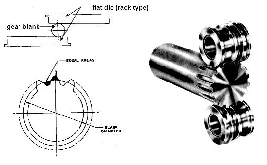
19 MANUFACTURE OF GEARS BY ROLLING The straight and helical teeth of disc or rod type external steel gears of small to medium diameter and module are generated by cold rolling by either flat dies or circular dies. Such rolling imparts high accuracy and surface integrity of the teeth which are formed by material flow unlike cutting. Gear rolling is reasonably employed for high productivity and high quality though initial machinery costs are relatively high. 19 Larger size gears are formed by hot rolling and then finished by machining.
20 20
21 POWDER METALLURGY Small size high quality external or internal spur, bevel or spiral gears are also produced by powder metallurgy process. Large size gears are rolled after briquetting and sintering for more strength and life. Powder metallurgically produced gears hardly require any further finishing work. 21
22 WIRE EDM Geometrically accurate but moderately finished straight toothed metallic spur gears, both external and internal type, can be produced by wire type Electro-discharge Machining (EDM). 22
23 PREFORMING GEAR BLANKS 23
24 Blanking in Press tool Plastic moulding Extrusion process 24
25 CASTING Sand casting Metal mould casting Die casting Investment casting Shell mould casting Centrifugal casting 25
26 GEAR FINISHING PROCESS 26
27 GEAR FINISHING PROCESS One of the goals of the gear finishing process in gears is to obtain a certain level of toughness in the gear teeth to reduce and/or eliminate bending and contact fatigue failures. Reduction of index undulation errors associated with helical gear teeth caused by the grinding process during the manufacture of the gears without degrading other gear accuracies (e.g. profile, tooth spacing) below levels required for precision (AGMA16 or DIN1) gears. A mold of the space between several gear teeth is obtained, with the mold having a length equal to or 27 greater than the wavelength of the undulation error to be reduced.
28 A micro finishing film is affixed to the mold and the mold is placed relative to a gear tooth so that the micro finishing film rests against a tooth surface having the undulation error. The grit size of the micro finishing film is such as to remove approximately 2 to 3 millionths of gear material with each pass through the teeth by the mold. Multiple passes are made by hand until the undulation error is reduced to an acceptable value. During the process the micro finishing film is replaced after approximately 3 or 4 passes and28the process is repeated for each tooth of the gear.
29 GEAR SHAVING Gear shaving is a gear finishing operation with high efficiency and high precision. When a work gear has been shaved by a shaving cutter with a true involute profile, the ''midconcave'' phenomena inevitably exist around the pitch points of the work gear tooth flanks. Aiming at this problem, a new-style shaving cutter with unequal depth gashes is designed and manufactured. Experiment has proven that the shaved gear has a 29 better surface finish that achieves the anticipated effect.
30 GEAR BURNISHING It is designed to remove or reduce gear tooth nicks and burrs, along with improving the smoothness of the tooth's active profile finish. The action of the burnishing dies on the tooth surface allows the machine to accomplish these quality improvements without altering the tooth profile or lead. Both internal and external gears are possible to burnish. 30
31 GEAR LAPPING Gear lapping is used to finish hardened gears by correcting small errors in spacing, profile, helix angle, and eccentricity. The operation is performed with all forms of gears running together with mating gears, and cast iron toothed laps, under a flow of fine oil mixed with an abrasive compound. 31
32 BOOKS Workshop Technology by B.S. Raghuwanshi Production Engineering Notes by S. K. Mondal 32
MANUFACTURING OF GEAR BOXES
 Profile No.: 29 NIC Code: 29301 MANUFACTURING OF GEAR BOXES 1. INTRODUCTION: Gears play a prominent role in mechanical power transmission. A gear or cogwheel is a rotating machine part having cut teeth,
GEAR NOISE REDUCTION BY NEW APPROACHES IN GEAR FINISHING PROCESSES
 GEAR NOISE REDUCTION BY NEW APPROACHES IN GEAR FINISHING PROCESSES Nikam Akshay 1, Patil Shubham 2, Pathak Mayur 3, Pattewar Vitthal 4, Rawanpalle Mangesh 5 1,2,3,4,5 Department of Mechanical Engineering,
11. GEAR TRANSMISSIONS
 11. GEAR TRANSMISSIONS 11.1. GENERAL CONSIDERATIONS Gears are one of the most important elements used in machinery. There are few mechanical devices that do not have the need to transmit power and motion
1 135 teeth to rack
 1. A spur gear with 46 teeth, 2.5 module has to be cut on a column and knee type horizontal milling machine with a rotary disc type form gear milling cutter. The 2.5 module cutter no. 3 is used on a blank
Gear Drives. A third gear added to the system will rotate in the same direction as the drive gear Equal diameters = Equal number of teeth = Same speed
 Gear Drive Systems Gear Drives Gear Drive: Synchronous mechanical drive that uses gears to transfer power Gear: A toothed wheel that meshes with other toothed wheels to transfer rotational power Pinion
CH#13 Gears-General. Drive and Driven Gears 3/13/2018
 CH#13 Gears-General A toothed wheel that engages another toothed mechanism in order to change the speed or direction of transmitted motion The gear set transmits rotary motion and force. Gears are used
Lecture (7) on. Gear Measurement. By Dr. Emad M. Saad. Industrial Engineering Dept. Faculty of Engineering. Fayoum University.
 on. Gear Measurement. By Dr. Emad M. Saad. Industrial Engineering Dept. Faculty of Engineering. Fayoum University.") 1 Lecture (7) on Gear Measurement Fayoum University By Dr. Emad M. Saad Industrial Engineering Dept. Faculty of Engineering Fayoum University Faculty of Engineering Industrial Engineering Dept. 2015-2016
1 Lecture (7) on Gear Measurement Fayoum University By Dr. Emad M. Saad Industrial Engineering Dept. Faculty of Engineering Fayoum University Faculty of Engineering Industrial Engineering Dept. 2015-2016
Part VII: Gear Systems: Analysis
 Part VII: Gear Systems: Analysis This section will review standard gear systems and will provide the basic tools to perform analysis on these systems. The areas covered in this section are: 1) Gears 101:
Metrology Prof. Dr Kanakuppi Sadashivappa Bapuji Institute of Engineering and Technology Davangere. Lecture 25 Introduction of Gears
 Metrology Prof. Dr Kanakuppi Sadashivappa Bapuji Institute of Engineering and Technology Davangere Lecture 25 Introduction of Gears I welcome you for the series of lecture on gear measurement and at module
Quindos the Ultimate Software package for Gears, Gear Tools and other Special Applications
 Quindos the Ultimate Software package for Gears, Gear Tools and other Special Applications Quindos gear packages Gearings Cylindrical Gear Unknown Gear Involute & Lead Master Straight Bevel Gear Spiral
 DEPARTMENT OF MECHANICAL ENGINEERING Subject code: ME6601 Subject Name: DESIGN OF TRANSMISSION SYSTEMS UNIT-I DESIGN OF TRANSMISSION SYSTEMS FOR FLEXIBLE ELEMENTS 1. What is the effect of centre distance
(POWER TRANSMISSION Methods)
") UNIT-5 (POWER TRANSMISSION Methods) It is a method by which you can transfer cyclic motion from one place to another or one pulley to another pulley. The ways by which we can transfer cyclic motion are:-
UNIT-5 (POWER TRANSMISSION Methods) It is a method by which you can transfer cyclic motion from one place to another or one pulley to another pulley. The ways by which we can transfer cyclic motion are:-
DUDLEY'S" HANDBOOK OF PRACTICAL GEAR DESIGN AND MANUFACTURE. Stephen P. Radzevich
 Second Edition DUDLEY'S" HANDBOOK OF PRACTICAL GEAR DESIGN AND MANUFACTURE Stephen P. Radzevich LßP) CRC Press VV J Taylors Francis Group Boca Raton London New York CRC Press is an imprint of the Taylor
GEAR CONTENTS POWER TRANSMISSION GEAR TYPES OF GEARS NOMENCLATURE APPLICATIONS OF GEARS VELOCITY RATIO GEAR TRAINS EXAMPLE PROBLEMS AND QUESTIONS
 GEAR CONTENTS POWER TRANSMISSION GEAR TYPES OF GEARS NOMENCLATURE APPLICATIONS OF GEARS VELOCITY RATIO GEAR TRAINS EXAMPLE PROBLEMS AND QUESTIONS GEAR.. Power transmission is the movement of energy from
1.6 Features of common gears
 1.6 Features of common gears Chapter 1.2 covered briefly on types of gear. The main gear features are explained here. Helical gear Helical gear has characteristics of transferability of larger load, less
Therefore, it is the general practice to test the tooth contact and backlash with a tester. Figure 19-5 shows the ideal contact for a worm gear mesh.
 19. Surface Contact Of Worm And Worm Gear There is no specific Japanese standard concerning worm gearing, except for some specifications regarding surface contact in JIS B 1741. Therefore, it is the general
GIRTH GEARS AND PINIONS OVERVIEW
 GIRTH GEARS AND PINIONS OVERVIEW Girth Gears & Pinions Tubular mills and rotary kiln operations are the life support system for the processing industries, and necessitates reliable and uninterrupted operations.
Sheet 1 Variable loading
 Sheet 1 Variable loading 1. Estimate S e for the following materials: a. AISI 1020 CD steel. b. AISI 1080 HR steel. c. 2024 T3 aluminum. d. AISI 4340 steel heat-treated to a tensile strength of 1700 MPa.
Gear Tooth Geometry - This is determined primarily by pitch, depth and pressure angle
 Gear Tooth Geometry - This is determined primarily by pitch, depth and pressure angle Addendum: The radial distance between the top land and the pitch circle. Addendum Circle: The circle defining the outer
UNIT -I. Ans: They are specified by the no. of strands & the no. of wires in each strand.
 VETRI VINAYAHA COLLEGE OF ENGINEERING AND TECHNOLOGY, THOTTIAM, NAMAKKAL-621215. DEPARTMENT OF MECHANICAL ENGINEERING SIXTH SEMESTER / III YEAR ME6601 DESIGN OF TRANSMISSION SYSTEM (Regulation-2013) UNIT
Technical Publications Catalog. April 2014
 Technical Publications Catalog April 2014 Table of Contents American Gear Manufacturers Association... iii How to Purchase Documents... 1 Index of AGMA Standards and Information Sheets by Number... 1 Index
KINGS COLLEGE OF ENGINEERING DEPARTMENT OF MECHANICAL ENGINEERING
 KINGS COLLEGE OF ENGINEERING DEPARTMENT OF MECHANICAL ENGINEERING QUESTION BANK Sub Code/Name: ME 1352 DESIGN OF TRANSMISSION SYSTEMS Year/Sem: III / VI UNIT-I (Design of transmission systems for flexible
Technical Publications Catalog. October 2015
 Technical Publications Catalog October 2015 Table of Contents How to Purchase Documents... 1 Index of AGMA Standards and Information Sheets by Number... 1 Index of AGMA Standards and Information Sheets
ME6601 DESIGN OF TRANSMISSION SYSTEMS
 SYED AMMAL ENGINEERING COLLEGE (Approved by the AICTE, New Delhi, Govt. of Tamilnadu and Affiliated to Anna University, Chennai) Established in 1998 - An ISO 9001:2008 Certified Institution Dr. E.M.Abdullah
Technology of Machine Tools
 PowerPoint to accompany Technology of Machine Tools 6 th Edition Krar Gill Smid Gear Cutting Unit 70 Copyright The McGraw-Hill Companies, Inc. Permission required for reproduction or display. 70-2 Objectives
Gear Measurement. Lecture (7) Mechanical Measurements
 Mechanical Measurements") 18 3. Gear profile checking 2. Involute measuring machine In this method the gear is held on a mandrel and circular disc of same diameter as the base circle of gear for the measurement is fixed on the
18 3. Gear profile checking 2. Involute measuring machine In this method the gear is held on a mandrel and circular disc of same diameter as the base circle of gear for the measurement is fixed on the
12/6/2013 9:09 PM. Chapter 13. Gears General. Dr. Mohammad Suliman Abuhaiba, PE
 Chapter 13 Gears General 1 2 Chapter Outline 1. Types of Gears 2. Nomenclature 3. Conjugate Action 4. Involute Properties 5. Fundamentals 6. Contact Ratio 7. Interference 8. The Forming of Gear Teeth 9.
Technical Publications Catalog. October 2016
 Technical Publications Catalog October 2016 Table of Contents How to Purchase Documents... 1 Index of AGMA Standards and Information Sheets by Number... 1 Index of AGMA Standards and Information Sheets
A Study on Noncircular Gears with Non-Uniform Teeth
 A Study on Noncircular Gears with Non-Uniform Teeth Kazushi Kumagai* 1 and Tetsuya Oizumi* *1 Department of Infomation System, Sendai National College of Technology 4-16-1 Ayashi-Chuo, Aoba-ku, Sendai
Specializing In High Performance Solid Carbide Cutting Tools
 Specializing In High Performance Solid Carbide Cutting Tools High Performance Products For Shops That Seek Productivity SERIES 156 VAR-A-TECH SERIES 101 ROUGHER SERIES 191 PRO-4 Vol. 0213 Series 110 for
1/2/2015 2:04 PM. Chapter 13. Gears General. Dr. Mohammad Suliman Abuhaiba, PE
 Chapter 13 Gears General 1 2 Chapter Outline 1. Types of Gears 2. Nomenclature 3. Conjugate Action 4. Involute Properties 5. Fundamentals 6. Contact Ratio 7. Interference 8. The Forming of Gear Teeth 9.
Bevel Gears. Fig.(1) Bevel gears
 Bevel gears") Bevel Gears Bevel gears are cut on conical blanks to be used to transmit motion between intersecting shafts. The simplest bevel gear type is the straighttooth bevel gear or straight bevel gear as can be
Bevel Gears Bevel gears are cut on conical blanks to be used to transmit motion between intersecting shafts. The simplest bevel gear type is the straighttooth bevel gear or straight bevel gear as can be
PROMAX. Tools. Feel The Edge. Winning The World Over One Amazing Tool At A Time. Specializing In High Performance Solid Carbide Cutting Tools
 PROMAX Tools Feel The Edge Specializing In High Performance Solid Carbide Cutting Tools VAR-A-TECH Winning The World Over One Amazing Tool At A Time SERIES 101 ROUGHER PRO-4 Vol. 1108A SPECIALS High Performance
Table of Contents. Standard Taps
 Table of Contents Standard Taps Standard Taps--High Speed Steel Machine Screw Sizes... 3 Standard Taps--High Speed Steel Hand Taps (Fractional Sizes)... 5 Standard Taps--High Speed Steel Machine Screw
Introduction to Gear Design
 Introduction to Gear Design Course No: M03-016 Credit: 3 PDH Robert P. Tata, P.E. Continuing Education and Development, Inc. 9 Greyridge Farm Court Stony Point, NY 10980 P: (877) 322-5800 F: (877) 322-4774
Tribology Aspects in Angular Transmission Systems
 Tribology Aspects in Angular Transmission Systems Part II Straight Bevel Gears Dr. Hermann Stadtfeld (This is the second of an eight-part series on the tribology aspects of angular gear drives. Each article
INVOLUTE SPIRAL FACE COUPLINGS AND GEARS: DESIGN APPROACH AND MANUFACTURING TECHNIQUE
 УДК 621.9.015 Dr. Alexander L. Kapelevich, Stephen D. Korosec 38 INVOLUTE SPIRAL FACE COUPLINGS AND GEARS: DESIGN APPROACH AND MANUFACTURING TECHNIQUE This paper presents spiral face gears with an involute
Chapter 8 Kinematics of Gears
 Chapter 8 Kinematics of Gears Gears! Gears are most often used in transmissions to convert an electric motor s high speed and low torque to a shaft s requirements for low speed high torque: Speed is easy
KISSsoft 03/2013 Tutorial 15
 KISSsoft 03/2013 Tutorial 15 Bevel gears KISSsoft AG Rosengartenstrasse 4 8608 Bubikon Switzerland Tel: +41 55 254 20 50 Fax: +41 55 254 20 51 info@kisssoft.ag www.kisssoft.ag Contents 1 Starting KISSsoft...
PRODUCTS AND SERVICES 2017
 PRODUCTS AND SERVICES 2017 www.wagears.com.au INTRODUCTION WA Gears Pty Ltd is a precision gear manufacturing company based in Henderson, Western Australia. We specialise in manufacturing gears and precision
Ernie Reiter and Irving Laskin
 F I N E P I T C H, P L A S T I C FA C E G E A R S : Design Ernie Reiter and Irving Laskin Ernie Reiter is a consultant specializing in the design of gears and geared products. He has authored modern software
1.7 Backlash. Summary of the backlash is play or clearance between one pair of gear. Fig. 17 Backlash
 1.7 Backlash Summary of the backlash is play or clearance between one pair of gear. Fig. 17 Backlash Great care is taken to produce the gear with zero deviation. However we are unable to completely eliminate
Topic 1. Basics of Oil Hydraulic Systems
 Topic 1. Basics of Oil Hydraulic Systems Fluid power Fluid power is the technology that deals with the generation, control and transmission of forces and movement of mechanical element or system with the
Small Tool Instruments and Data Management
 Small Tool Instruments and Data Management Digital Micrometers Pages 28 34 Analogue Micrometers Pages 35 42 Special Version Micrometers Pages 43 63 External screw type micrometers accessories Pages 65
KISSsoft 03/2017 Tutorial 15
 KISSsoft 03/2017 Tutorial 15 Bevel gears KISSsoft AG Rosengartenstrasse 4 8608 Bubikon Switzerland Tel: +41 55 254 20 50 Fax: +41 55 254 20 51 info@kisssoft.ag www.kisssoft.ag Contents 1 Starting KISSsoft...
Program Internal Gear Set Profile Shift Coefficients With Zero Backlash Introduction
 Program 60-107 Internal Gear Set Profile Shift Coefficients With Zero Backlash Introduction The purpose of this model is to provide data for a gear set when the tooth thickness and/or the center distance
All levers are one of three types, usually called classes. The class of a lever depends on the relative position of the load, effort and fulcrum:
 Página 66 de 232 Mechanisms A mechanism is simply a device which takes an input motion and force, and outputs a different motion and force. The point of a mechanism is to make the job easier to do. The
TECHNICAL PAPER. New Opportunities with Molded Gears. by: R.E. Kleiss, A.L. Kapelevich and N.J. Kleiss Jr., Kleiss Gears, Inc.
 01FTM9 New Opportunities with Molded Gears by: R.E. Kleiss, A.L. Kapelevich and N.J. Kleiss Jr., Kleiss Gears, Inc. American Gear Manufacturers Association TECHNICAL PAPER New Opportunities with Molded
SECTION 8 BEVEL GEARING
 SECTION 8 BEVEL GEARING For intersecting shafts, bevel gears offer a good means of transmitting motion and power. Most transmissions occur at right angles, Figure 8-1, but the shaft angle can be any value.
WILTON SAWING. Horizontal Bandsaw s Vertical Bandsaws Cold Saws Cold Saw Blades Accessories... 32
 Horizontal Bandsaw s........................... 18 Vertical Bandsaws.............................. 24 Cold Saws.................................... 27 Cold Saw Blades............................... 31
Extremely small dimensions, extremely high precision.
 Product innovations Edition 2011-1 Drilling and threading _TOOL INNOVATIONS IN DRILLING Extremely small dimensions, extremely high precision. SOLID CARBIDE DRILLS Walter Titex X treme the universal high-performance
Performance requires quality.
 131 - With straight shank and square - Left-hand spiral 7-8 - First cut 1/4 of the cutting length (l 2 ) - Accuracy Hand Reamers DIN 26. Not suitable for blind holes. d 1 l 2 l 1 d 2 131 2, 25 5 1,6 21
Determination and improvement of bevel gear efficiency by means of loaded TCA
 Determination and improvement of bevel gear efficiency by means of loaded TCA Dr. J. Thomas, Dr. C. Wirth, ZG GmbH, Germany Abstract Bevel and hypoid gears are widely used in automotive and industrial
Catalog Q Conversion For those wishing to ease themselves into working with metric gears
 1.3.4 Conversion For those wishing to ease themselves into working with metric gears by looking at them in terms of familiar inch gearing relationships and mathematics, Table 1-5 is offered as a means
121 indexable. Butt WelDeD tools. Die heads & chasers. restorers. Page Page sheet & tube Drills. Drills. Page Page...
 group 010 Butt WelDeD tools group 016 Die heads & chasers group 017 thread restorers Page...........................18 Page...........................19 Page...........................19 group 019 sheet
Instantaneous Centre Method
 Instantaneous Centre Method The combined motion of rotation and translation of the link AB may be assumed to be a motion of pure rotation about some centre I, known as the instantaneous centre of rotation.
Tribology Aspects in Angular Transmission Systems
 Tribology Aspects in Angular Transmission Systems Part VI: Beveloid & Hypoloid Gears Dr. Hermann Stadtfeld (This article is part six of an eight-part series on the tribology aspects of angular gear drives.
Gear Engineering Data. Spur Gear Gear Formulas Drive Selection Horsepower and Torque Tables
 Engineering Gear Engineering Data Spur Gear Gear Formulas Drive Selection Horsepower and Torque Tables G-79 Gear Selection Stock Spur Gear Drive Selection When designing a stock gear drive using the horsepower
FUNCTION OF A BEARING
 Bearing FUNCTION OF A BEARING The main function of a rotating shaft is to transmit power from one end of the line to the other. It needs a good support to ensure stability and frictionless rotation. The
EXAMPLES GEARS. page 1
 (EXAMPLES GEARS) EXAMPLES GEARS Example 1: Shilds p. 76 A 20 full depth spur pinion is to trans mit 1.25 kw at 850 rpm. The pinion has 18 teeth. Determine the Lewis bending stress if the module is 2 and
Lecture 13 BEVEL GEARS
 Lecture 13 BEVEL GEARS CONTENTS 1. Bevel gear geometry and terminology 2. Bevel gear force analysis 3. Bending stress analysis 4. Contact stress analysis 5. Permissible bending fatigue stress 6. Permissible
TECHNOLOGY MECHANISMS
 TECHNOLOGY MECHANISMS 3º ESO IES CHAN DO MONTE URTAZA 1 WHAT IS A MECHANISM? Mechanism are devices that have been designed to make jobs easier. They all have certain things in common: They involve some
CHAPTER 3 page 35 PRINCIPLES OF GEAR-TOOTH GENERATION. .1 Angular Velocity Ratio
 CHAPTER 1 page 1..., ATURE, NOTATION AND CONVENTIONS TYPES OF GEAR 1.1 Spur 1.2 Helical 1.3 Double-Helical 1.4 Crossed Helical 1.5 Conical Involute 1.6 Bevel 1.7 Spiral Bevel 1.8 Hypoid 1.9 Worm NOMENCLATURE
d -2,5 26,5 mm D -3,4 33 mm L mm; МК D mm L mm D mm L mm
 KAMAZ Publicly Traded Company Repair and Tooling Plant Tool making 2018 Twist drills Auger drills Drills with a thickened core Centre drills Twist step drills Solid carbide drills Inserted-blade drills
Effect of Geometry Factor I & J Factor Multipliers in the performance of Helical Gears
 Effect of Geometry Factor I & J Factor Multipliers in the performance of Helical Gears 1 Amit D. Modi, 2 Manan B. Raval, 1 Lecturer, 2 Lecturer, 1 Department of Mechanical Engineering, 2 Department of
HP High-Performance Gear Units with <2' Adjustable Backlash
 Page HP High-Performance Gear Units with
Figure 1.1 "Bevel and hypoid gears" "Modules" Figure / August 2011 Release 03/2011
 KISSsoft Tutorial 015: Bevel Gears KISSsoft AG - +41 55 254 20 50 Uetzikon 4 - +41 55 254 20 51 8634 Hombrechtikon - info@kisssoft. AG Switzerland - www. KISSsoft. AG KISSsoft Tutorial: Bevel Gears 1 Starting
Chapter seven. Gears. Laith Batarseh
 Chapter seven Gears Laith Batarseh Gears are very important in power transmission between a drive rotor and driven rotor What are the functions of gears? - Transmit motion and torque (power) between shafts
Chain Drives. Pitch. Basic Types -There are six major types of power-
 1 2 Power transmission chains have two things in common; side bars or link plates, and pin and bushing joints. The chain articulates at each joint to operate around a toothed sprocket. The pitch of the
Mechanotechnology N3 Lecturer s Guide
 Mechanotechnology N3 Lecturer s Guide ISBN: 978-1-4308-0617-2 R Cameron & LL Maraschin This Lecturer s Guide accompanies the following Student s Book: Title: Mechanotechnology N3 Author: R Cameron & LL
API 613, FIFTH EDITION, SPECIAL PURPOSE GEAR UNITS FOR PETROLEUM, CHEMICAL AND GAS INDUSTRY SERVICES OVERVIEW PRESENTATION
 API 613, FIFTH EDITION, SPECIAL PURPOSE GEAR UNITS FOR PETROLEUM, CHEMICAL AND GAS INDUSTRY SERVICES OVERVIEW PRESENTATION by Robert W. (Wes) Conner Machinery Engineer Fluor Daniel Sugarland, Texas and
Chapter 1 Gear Design
 Chapter 1 Gear Design GTU Paper Analysis Sr. No. Questions Nov 16 May 17 Nov 17 May 18 Theory 1. Explain the following terms used in helical gears: (a) Helix angle; (b) Normal pitch; (c) Axial pitch; (d)
DESIGN OF MACHINE ELEMENTS UNIVERSITY QUESTION BANK WITH ANSWERS. Unit 1 STEADY STRESSES AND VARIABLE STRESSES IN MACHINE MEMBERS
 DESIGN OF MACHINE ELEMENTS UNIVERSITY QUESTION BANK WITH ANSWERS Unit 1 STEADY STRESSES AND VARIABLE STRESSES IN MACHINE MEMBERS 1.Define factor of safety. Factor of safety (FOS) is defined as the ratio
LAPPING OR GRINDING? WHICH TECHNOLOGY IS THE RIGHT CHOICE IN THE AGE OF INDUSTRY 4.0?
 LAPPING OR GRINDING? WHICH TECHNOLOGY IS THE RIGHT CHOICE IN THE AGE OF INDUSTRY 4.0? Bevel gear transmissions for the automotive industry are subject to extremely stringent requirements. They must be
Bibliography. [1] Buckingham, Earle: "Analytical Mechanics of Gears", McGraw-Hill, New York, 1949, and republished by Dover, New York, 1963.
![Bibliography. [1] Buckingham, Earle: Analytical Mechanics of Gears, McGraw-Hill, New York, 1949, and republished by Dover, New York, 1963.](/thumbs/87/96820687.jpg "Bibliography. [1] Buckingham, Earle: Analytical Mechanics of Gears, McGraw-Hill, New York, 1949, and republished by Dover, New York, 1963.") Bibliography The first five references listed are books on gearing. Some of them deal not only with the geometry, but also with many other aspects of gearing. However, the books are included in this bibliography
Bibliography The first five references listed are books on gearing. Some of them deal not only with the geometry, but also with many other aspects of gearing. However, the books are included in this bibliography
MODULE- 5 : INTRODUCTION TO HYDROSTATIC UNITS (PUMPS AND MOTORS)
") MODULE- 5 : INTRODUCTION TO HYDROSTATIC UNITS (PUMPS AND MOTORS) LECTURE- 18 : BASIC FEATURES OF SOME Hydraulic Pumps & Motors Introduction In this section we shall discuss the working principles and fundamental
MODULE- 5 : INTRODUCTION TO HYDROSTATIC UNITS (PUMPS AND MOTORS) LECTURE- 18 : BASIC FEATURES OF SOME Hydraulic Pumps & Motors Introduction In this section we shall discuss the working principles and fundamental
'' ''' '' ''' Code No: R R16 SET - 1
 Code No: R161232 R16 SET - 1 1. a) List the Primary requirements of a Steam Boiler. (2M) b) What are the distinguishing features between a Casting and a Pattern? (2M) c) Define (i) Brake Power; (ii) Indicated
AGMA Catalog of Technical Publications
 Topic AGMA Catalog of Technical Publications 2000-2007 TABLE OF CONTENTS American Gear Manufacturers Association... ii How to Purchase ocuments... iii Index of AGMA Standards and Information Sheets by
Marine Engineering Exam Resource Review of Couplings
 1. What are rigid couplings used for? Used to join drive shafts together. True alignment and rigidity are required. Example Drive shafts and production lines, bridge cranes, solid shaft that needs to be
GEARBOXES. Gearboxes. Gearboxes. Gearbox is a mechanical device utilized to increase the output torque or change
 GEARBOXES Gearboxes Gearboxes Gearbox is a mechanical device utilized to increase the output torque or change the speed of a motor. The motor's shaft is attached to one end of the gearbox and through the
Bevel Gears. Catalog Number of KHK Stock Gears. Bevel Gears M BS G R. Gears. Spur. Helical. Gears. Internal. Gears. Racks. CP Racks.
 MHP High-Ratio Hypoid Ground Spiral G Ground Spiral 15 ~ 200 2 m1, 1.5 Page 456 m2 ~ 4 Page 458 m2 ~ 4 Page 460 Spur MBSA MBSB Finished Bore Spiral Spiral 1.5 ~ 4 SBZG Ground Zerol 1.5, 2 Helical m2 ~
Mechanics and Mechanisms. What is do you think about when you hear the word mechanics? Mechanics. Is this a mechanism? 2/17/2011
 Mechanics and Mechanisms What is do you think about when you hear the word mechanics? Mechanics Mechanics is the study of how things move Is this a mechanism? Concerned with creating useful movement through
RE-EQUIPPING OF GEAR HOBBING MACHINE: NUMERICAL CONTROL INNOVATION BASED ON PLC AND SERVOMECHANISM
 RE-EQUIPPING OF GEAR HOBBING MACHINE: NUMERICAL CONTROL INNOVATION BASED ON PLC AND SERVOMECHANISM 1 OMKAR KADAM, 2 BALIRAM JADHAV, 3 SHRIKANT PAWAR 1 M.Tech, Production Engineering, Mechanical Engineering
Case Study Involving Surface Durability and Improved Surface Finish
 Case Study Involving Surface Durability and Improved Surface Finish G. Blake and J. Reynolds (Printed with permission of the copyright holder, the American Gear Manufacturers Association, 500 Montgomery
The Power Of Technology & Precision
 The Power Of Technology & Precision A Regal Brand Over 90 Years of Experience! Value Proposition Milwaukee Gear manufactures custom steel gears, pinions and assemblies to OEM market leaders that require
1. (a) Discuss various types of Kinematic links with examples. (b) Explain different types of constrained motions with examples.
 Discuss various types of Kinematic links with examples. (b) Explain different types of constrained motions with examples.") Code No: RR310304 Set No. 1 III B.Tech I Semester Supplementary Examinations, February 2007 KINEMATICS OF MACHINERY ( Common to Mechanical Engineering, Mechatronics and Production Engineering) Time: 3
Code No: RR310304 Set No. 1 III B.Tech I Semester Supplementary Examinations, February 2007 KINEMATICS OF MACHINERY ( Common to Mechanical Engineering, Mechatronics and Production Engineering) Time: 3
AN OPTIMAL PROFILE AND LEAD MODIFICATION IN CYLINDRICAL GEAR TOOTH BY REDUCING THE LOAD DISTRIBUTION FACTOR
 AN OPTIMAL PROFILE AND LEAD MODIFICATION IN CYLINDRICAL GEAR TOOTH BY REDUCING THE LOAD DISTRIBUTION FACTOR Balasubramanian Narayanan Department of Production Engineering, Sathyabama University, Chennai,
Mechanism Feasibility Design Task
 Mechanism Feasibility Design Task Dr. James Gopsill 1 Contents 1. Last Week 2. Types of Gear 3. Gear Definitions 4. Gear Forces 5. Multi-Stage Gearbox Example 6. Gearbox Design Report Section 7. This Weeks
Tooth thickness Dedendum. Addendum. Centre distance Nominal
 FORMULAS SPUR GEARS TO FIND:- PCD ØD MODULE No. of TEETH CP ADDENDUM DEDENDUM MODULE No. of TEETH x MOD (mm) (No. of TEETH + ) x MOD (mm) 5.4 MODULE CP π (mm) PCD MODULE (mm) MODULE x π (mm) MODULE (mm)
Sample BD Tech Concepts LLC. Introduction to. Gear Design. 2 nd Edition. Charles D. Schultz, p.e. Beyta Gear Service. Winfield, IL
 Introduction to Gear Design 2 nd Edition Charles D. Schultz, p.e. Beyta Gear Service Winfield, IL For information, contact: Beyta Gear Service Charles D. Schultz, p.e. 0N230 County Farm Road Winfield,
INTRODUCTION: Rotary pumps are positive displacement pumps. The rate of flow (discharge) of rotary pump remains constant irrespective of the
 of rotary pump remains constant irrespective of the") INTRODUCTION: Rotary pumps are positive displacement pumps. The rate of flow (discharge) of rotary pump remains constant irrespective of the pressure. That is, even at very high pressure, these pumps can
INTRODUCTION: Rotary pumps are positive displacement pumps. The rate of flow (discharge) of rotary pump remains constant irrespective of the pressure. That is, even at very high pressure, these pumps can
GatesFacts Technical Information Library Gates Compass Power Transmission CD-ROM version 1.2 The Gates Rubber Company Denver, Colorado USA
 SELECTING SYNCHRONOUS BELTS FOR PRECISE POSITIONING A W Wallin Power Transmission Design February, 1989 Synchronous belts are well known for precise positioning. However, some precision applications require
Solid carbide Twist Drills Overview
 Solid carbide Twist Drills Overview Manufacturer ß 000000000000 DIN similar to 899 338 338 338 6539 6539 6539 6539 6539 6539 6539 6539 6539 Counters.cut.Counters.cut. 3 x D 3 x D 3 x D, IKZ 3 x D, IKZ
Finite element analysis of profile modified spur gear
 Finite element analysis of profile modified spur gear Sagar Gaur Mechanical Engineering Department, Institute of Technology, YashluvVirwani Mechanical Engineering Department, Institute of Technology, Rudresh
1.8 Rack shift of the gear
 1.8 Rack shift of the gear Undercut When Number of teeth is belo minimum as shon in Fig. 3, part of dedendum is no longer an Involute curve but ill look like a shape scooped out by cutter tool. Refer to
Design and Analysis of High Speed Helical Gear By Using Ansys
 Design and Analysis of High Speed Helical Gear By Using Ansys A. Sai Bharath*1, T.v.s.r.k. Prasad*2 M.Tech Student (Cad/ Cam) Mechanical Engineering, NCET, Jupudi, Ibrahimpatnam, Vijayawada, Krishna (dt),a.p,
BEARING GUIDE. Bearing Guide Created by REV Robotics 2016, Licensed Under CC BY-SA 1
 fg BEARING GUIDE This guide is intended as a reference on how to build with the new REV Robotics 15mm Building System using bearings and brackets to achieve basic motion. Bearing Guide Created by REV Robotics
HSS ground for steel to 900 N/mm 2, aluminium alloys, brass, bronze. Use For producing screw through-holes DIN EN 20273,
 Drilling Tools Step drills 184 Step drills T - Countersink angle - With straight shank - Cone envelope grind - Web-thinned chisel edge and surface treatment For producing threaded core holes and countersinks
MECH 1200 Quiz 2 Review
 Name: Class: Date: MECH 1200 Quiz 2 Review True/False Indicate whether the statement is true or false. 1. Gears are machined toothed wheels that engage other toothed wheels to transfer power and torque.
CHAPTER 5 PREVENTION OF TOOTH DAMAGE IN HELICAL GEAR BY PROFILE MODIFICATION
 90 CHAPTER 5 PREVENTION OF TOOTH DAMAGE IN HELICAL GEAR BY PROFILE MODIFICATION 5.1 INTRODUCTION In any gear drive the absolute and the relative transmission error variations normally increases with an