MPFI FUEL INJECTION SYSTEM
|
|
|
- Reynard Hunt
- 5 years ago
- Views:
Transcription


1 MPFI FUEL INJECTION SYSTEM PART NUMBERS thru , & INSTALLATION & TUNING MANUAL 199R10762 NOTE: These instructions must be read and fully understood before beginning installation. If this manual is not fully understood, installation should not be attempted. Failure to follow these instructions, including the pictures may result in subsequent system failure. 1
2 TABLE OF CONTENTS: 1.0 INTRODUCTION WARNINGS, NOTES, AND NOTICES PARTS IDENTIFICATION ADDITIONAL ITEMS REQUIRED FOR INSTALLATION TOOLS REQUIRED FOR INSTALLATION REMOVAL OF EXISTING COMPONENTS TERMINATOR MPFI SYSTEM INSTALLATION Fuel Pump, Fuel Line, and Filter Installation Oxygen Sensor Installation Oxygen Sensor Mounting Procedure ECU Mounting WIRING Important Wiring Do s and Don ts WIRING HARNESS INSTALLATION Main Power/Battery Connection PRIMARY HARNESS INSTALLATION AND SENSOR CONNECTIONS ECU Connectors Harness Routing Sensor Connections & Outputs Oil Pressure Sensor Coolant Temperature Sensor (CTS) Wide Band Oxygen Sensor (WB02) Fuel Pressure (Fuel) Manifold Air Temperature (MAT) Cam Sensor Crank Sensor Knock Sensors Manifold Absolute Pressure sensor (MAP) Throttle Position Sensor (TPS) Idle Air Control (IAC) Fuel Injectors Ignition Coils Coil Ground Wires Handheld Connections - (CAN1) LOOSE WIRES ADDITIONAL OUTPUTS TRANSMISSION HARNESS Transmission Wiring DRIVE-BY-WIRE HARNESS Overview Warnings! Installation System Safeties Throttle Body Limp Home Position Drive-By-Wire DO S and DON TS Wiring APPENDIX 1.0 PINOUT PREVIOUS INSTALLATION REQUIRED TERMINATOR INSTRUCTIONS AND TUNING INITIAL POWER-UP HANDHELD NAVIGATION & USE Making Adjustments HOME SCREEN CALIBRATION WIZARD TPS AUTOSET TRANSMISSION SETUP Transmission Trans Setup Speed Calc SENSOR VERIFICATION STARTUP AFTER-STARTUP IDLE SETTING/CABLE OPERATED THROTTLE PLATE SETTING SELF-TUNING GAUGE SCREENS Monitor Multi-Gauge Monitors
3 Diagnostics Custom Setups Dash Setup Channels Scaling FILE SAVING/LOADING File ECU Overview ECU Globals ECU Data Logging ECU Hardware/Firmware (HW/FW) Local Setup BASIC TUNING Basic Fuel Target AFR Acceleration Enrichment Fuel Prime Fuel Learn Learn Enable/Disable Learn Speed Basic Idle Spark Transmission Shifts WOT Shifts Torque Converter Clutch (TCC) Parameters Torque Converter Clutch (TCC) (Un) Lock Line Pressure Drive-By-Wire Pedal vs Throttle SYSTEM SETUP System Tuning Outputs Engine Setup Ignition Setup ADVANCED TUNING Advanced Fuel Closed Loop Advanced Learn Advanced Idle IAC Rampdown IAC Speed IAC Startup Idle Spark APPENDIX 2.0 INJECTOR GROUPINGS AND INJECTOR CONNECTOR INFORMATION Injector Groups Injector Connectors EV EV6 / USCAR MULTEC APPENDIX 3.0 THROTTLE BODIES AND PEDALS PIN CONECTOR: PIN (EARLY TRUCK) CONNECTOR: Throttle Pedal APPENDIX 4.0 SENSOR DIAGNOSTICS AND STATUSES
4 1.0 INTRODUCTION Holley Performance Products has written this manual for the installation of the LS TERMINATOR MPFI fuel injection system. This manual contains the information necessary for the installation of the hardware contained in this kit, which includes the ECU, wiring, and 3.5 touch screen. It also contains all tuning information. This instruction sheet does not include installation instructions for the fuel system (pump, filters, regulators and lines). Please read all the WARNINGS and NOTES, as they contain valuable information that can save you time and money. It is our intent to provide the best possible products for our customer; products that perform properly and satisfy your expectations. Should you need information or parts assistance, please contact our technical service department at , Monday through Friday, 8 a.m. to 5 p.m. Central Time. By using this number, you may obtain any information and/or parts assistance that you may require. Please have the part number of the product you purchased when you call. 2.0 WARNINGS, NOTES, AND NOTICES NOTE: This system does not contain fuel system components that are required including the fuel pump, fuel filters, fuel pressure regulator, and lines. Holley offers complete kits can be purchased separately (526-1, 526-2, 526-3, & 526-4). NOTE: This system is designed for stock and mild cam, naturally aspirated LS engines. WARNING! The LS TERMINATOR MPFI systems consist of a number of sophisticated components. Failure of any one component does not constitute, nor does it justify, warranty of the complete system. Individual service items are available for replacement of components. If assistance is required or if you need further warranty clarification, you can call Holley Technical Service at the number shown above. WARNING! To preserve warranty, these instructions must be read and followed thoroughly and completely before and during installation. It is important that you become familiar with the parts and the installation of the LS TERMINATOR MPFI system before you begin. Failure to read and understand these instructions could result in damage to LS TERMINATOR MPFI components that are not covered by the warranty and could result in serious personal injury and property damage. WARNING! The oxygen sensor in this kit is recommended for use with ONLY unleaded fuel. Use of leaded fuels will degrade the oxygen sensor and will result in incorrect exhaust gas oxygen readings and improper fuel delivery. Failure to follow these directions does not constitute the right to a warranty claim. WARNING! Failure to follow all of the above will result in an improper installation, which may lead to personal injury, including death, and/or property damage. Improper installation and/or use of this or any Holley product will void all warranties. WARNING! Use of some RTV silicone sealers will destroy the oxygen sensor used with this product. Ensure the RTV silicone sealant you use is compatible with oxygen sensor vehicles. This information should be found on the RTV package. WARNING! For the safety and protection of you and others, only a trained mechanic having adequate fuel system experience must perform the installation, adjustment, and repair. It is particularly important to remember one of the very basic principles of safety: fuel vapors are heavier than air and tend to collect in low places where an explosive fuel/air mixture may be ignited by any spark or flame resulting in property damage, personal injury, and/or death. Extreme caution must be exercised to prevent spillage and thus eliminate the formation of such fuel vapors. WARNING! This type of work MUST be performed in a well-ventilated area. Do not smoke or have an open flame present near gasoline vapors or an explosion may result. 4
 1")
 1 554-114 2 TERMINATOR Hand-Held")

 1 558-103 5A Injector Harness (Kits")
 1 550-214 5C Injector Harness")

 1 558-429 8")


5 3.0 PARTS IDENTIFICATION ITEM DESCRIPTION QTY SERVICE PART 1A TERMINATOR EFI ECU (Kits , 610 & 614) B TERMINATOR EFI ECU (Kits , 611, 612, 613, 615, 622, 623) TERMINATOR Hand-Held Controller Main Power Harness A Main Engine Harness (Kits , 609 & thru ) B Main Engine Harness (Kits thru ) A Injector Harness (Kits & ) B Injector Harness (Kits thru ) C Injector Harness (Kits , 615, 622 & 623) Input/Output Harness A Drive-By-Wire Harness (Kits & ) B Drive-By-Wire Harness Early Truck (Kits & ) L60e/4L80e Transmission Harness CAN Power Harness CAN Extension Harness Oxygen Sensor Oxygen Sensor Weld Ring Service Parts: AMP Relay Optional Parts: PS Fuel Pressure Sender Item 1A Item 1B Item 2 Item 3 Item 4A Item 4B Item 5A Item 5B Item 5C Item 6 Item 7A Item 7B Item 8 Item 9 Item 10 Item 11 Item 12 Item 13 Item ADDITIONAL ITEMS REQUIRED FOR INSTALLATION Fuel System Return Fuel Lines A psi fuel gauge or pressure transducer is recommended to check for proper fuel pressure. PN is a PSI pressure sensor that can be purchased as well that will plug into the TERMINATOR harness to check and monitor fuel pressure. It requires a 1/8 NPT port for installation (Holley fuel pressure regulators have an 1/8 NPT port) These kits are designed to use factory sensors and injectors. Any deviation from this may require different harnesses. Please contact Holley Technical Services if your project is using any non-oem parts. 5
 (depending on ECU location) Terminal crimping tool Factory Service Manual for your vehicle 02 Bung Installation (drilling, welding) An assistant is necessary for some installation and")
6 5.0 TOOLS REQUIRED FOR INSTALLATION Standard wrench set Small blade screwdriver Allen Wrench set Medium blade screwdriver #2 Phillips screwdriver Digital Volt meter Drill and assorted bit sizes Hole saw (2 ) (depending on ECU location) Terminal crimping tool Factory Service Manual for your vehicle 02 Bung Installation (drilling, welding) An assistant is necessary for some installation and adjustment procedures and should be present for safety reasons. 6.0 REMOVAL OF EXISTING COMPONENTS 1. Disconnect the battery. 2. Remove the existing OEM main wiring harness and injector harness. Consult the factory service manual for details on how to properly remove the harness. 7.0 TERMINATOR MPFI SYSTEM INSTALLATION 7.1 Fuel Pump, Fuel Line, and Filter Installation A complete high pressure EFI fuel system must be installed for the TERMINATOR. The pump should be capable of supplying 255 liters/hour or 400 lb./hr. of fuel at 45 PSI. If using an in-line fuel pump, there should be a coarse pre-filter before the pump. All systems should contain a 10 micron post filter after the fuel pump. An EFI fuel pressure regulator is required. It should be installed after the throttle body. See Figure 4 below for proper fuel system plumbing. Holley offers four fuel system kits. These kits contain all components except the return line. They include detailed instructions (downloadable at These kits are: Braided Stainless Lines, Billet Pump, Regulator, and Filters Pro-Lite 350 Hose, Billet Pump, Regulator, and Filters Super Stock Hose, Billet Regulator, Fuel Pump, and Filter Super Stock Hose, Billet Regulator, Pump, and Metal Filters 7.2 Oxygen Sensor Installation Figure 4 The oxygen sensor should be mounted at a point where it can read a good average of all the cylinders on one bank. This would be slightly after all the cylinders merge. Do NOT mount the sensor far back in the exhaust as this will negatively impact closed loop operation response. If you have long tube headers, mount the sensor approximately 1-10 after the collector. You must have no less than of exhaust pipe after the sensor. TERMINATOR EFI systems come with a Bosch wideband oxygen sensor (Item 5). Make sure your sensor looks like Figure 5. Figure 5 6
7 7.2.1 Oxygen Sensor Mounting Procedure NOTE: Never run the engine with the oxygen sensor installed if it is not plugged in and powered by the ECU, or it will be damaged. If you need to plug the hole temporarily, use an O2 sensor plug or a spark plug with an 18mm thread. NOTE: Someone with experience in welding exhaust systems should install the oxygen sensor boss. Any competent exhaust shop will be able to perform this task at a minimum cost. (Note: If you weld on the car, make sure all wiring to the ECU is disconnected, and its best to remove the ECU from the vehicle when welding). WARNING! Use of leaded fuel will degrade an oxygen sensor. Prolonged use is not recommended unless periodic replacement is performed. WARNING! Use of some RTV silicone sealers will destroy the oxygen sensor used with this product. Ensure the RTV silicone sealant you use is compatible with oxygen sensor vehicles. This information should be found on the RTV package. 1. Locate a position for the oxygen sensor as close to the engine as possible. If your vehicle has catalytic converters, the oxygen sensor MUST be located between the engine and the catalytic converters. Figure 6 NOTE: The oxygen sensor should be mounted in such a way that the condensation in the exhaust tubing will not enter the sensor. Mount the O 2 sensor in the upper half of the exhaust tubing, with the angle x, shown above, being greater than 10. Figure 6 indicates that the sensor can be mounted on either side of the exhaust tubing. 2. Drill a 7/8 hole in the location picked for the sensor. Weld the threaded boss into the 7/8 hole. Weld all the way around the boss to insure a leak proof connection. Install the oxygen sensor into the threaded boss and tighten securely. It is a good idea to add antiseize to the threads to aid in removal. Do not get any anti-seize on the tip of the sensor. 3. On vehicles equipped with an AIR pump, the oxygen sensor must be mounted before the AIR injection into the exhaust, or the AIR pump must be disconnected. Holley recommends that if the AIR is injected into both exhaust manifolds, mount the oxygen sensor into the pipe immediately after the exhaust manifold. Disconnect the AIR pump tube from the exhaust manifold and plug both ends. Check with local ordinances for the legality of this procedure in your area. WARNING! Failure to disconnect the AIR pump or locating the oxygen sensor downstream from AIR injection will result in an extremely rich mixture, which could cause drivability problems and severe engine damage. 7.3 ECU Mounting The ECU can be mounted inside the passenger compartment (preferable location) or in the engine compartment. If mounted in the engine compartment, follow these guidelines: The ECU should be located such that it isn t being directly hit by water or road debris. It should also be located such that it isn t extremely close to exhaust manifolds or headers. It should be mounted such that it is as far away from spark plug wires, CD ignition boxes, or other electrically noisy devices as is reasonable possible. Make sure the connector end of the ECU is pointed DOWN such that water can t make its way into the ECU terminals. The ECU comes with mounting hardware (stainless steel screws and nuts). The ECU has plastic shoulders on the mounting ears. DO NOT REMOVE THEM. Do not over-tighten the mounting hardware if the ECU is not mounted on a flat surface. 8.0 WIRING This section overviews how to properly install the wiring harnesses for this system. 8.1 Important Wiring Do s and Don ts An EFI system depends heavily on being supplied a clean and constant voltage source. The grounds of an electrical system are just as important as the power side. TERMINATOR ECU s contain multiple processing devices that require clean power and ground sources. The wiring harnesses for them must be installed in such a manner that they are separated from dirty power and ground sources. 7
, ignition boxes and associated wiring.")
8 DO S Install the main power and ground directly to the battery. To the POSTS/TERMINALS, not to any other place. Keep sensor wiring away from high voltage or noisy/dirty components and wiring, especially secondary ignition wiring (plug wires), ignition boxes and associated wiring. It is best that the plug wires not physically contact any EFI wires. Properly crimp or crimp and solder any wire connections. Apply quality heat shrink over any of these connections. It is critical that the engine has a proper ground connection to the battery and chassis. DON TS NEVER run high voltage or noisy/dirty wires in parallel (bundle/loom together) with any EFI sensor wiring. If wires need to cross, try to do so at an angle. Do not use the electric fan outputs to directly power a fan. They must only trigger a relay. Do not use improper crimping tools. Don t use things like t-taps, etc. Use proper crimpers/solder and heat shrink. It is never recommended to splice/share signal wires (such as TPS, etc.) between different electronic control units (i.e. piggyback ). Do not connect the red/white switched +12V wire to dirty sources, such as the ignition coil, audio systems, or 12V sources connected to HID head lamps. 9.0 WIRING HARNESS INSTALLATION 9.1 Main Power/Battery Connection The TERMINATOR ECU has a main battery power and ground connector on the right side of the ECU. The bottom position, Terminal A is the ground (black wire). The black wire should go to the negative post DIRECTLY on the battery. The upper position, Terminal B is the positive terminal (red wire). The red wire should go to the positive post DIRECTLY on the battery. If you have a dual post battery, it is a great idea to purchase separate posts/studs to connect the ECU power and ground to the non-used terminals. Always use the fused power cable (Item 3) with the proper connectors supplied by Holley only. Don t connect to the ECU until after ALL wiring and installation is performed. Figure PRIMARY HARNESS INSTALLATION AND SENSOR CONNECTIONS These sections review the Main Harness installation and sensor connections that must be completed. The Main Harness (Item 4) is the primary harness that supports all the primary engine sensors, fuel and ignition. There are two main connectors for this harness that plug into the ECU. Figure 8 8
.")

9 10.1 ECU Connectors TERMINATOR ECU The TERMINATOR ECU has two main connectors: J1A - The first connector next to the USB connector is the J1A connector (34 pin). This connector is primarily an Input connector. It contains all the sensor inputs and wide band oxygen sensor control. J1B - The second connector is the J1B connector (26 pin). This connector is the output connector. It has 8 injector outputs and outputs for other devices. J2A Not used with Terminator kits. J2B Not used with Terminator kits. J3 Connection point for the Drive-By-Wire harness. J4 Connection point for the Transmission harness The ECU above is used in Kits , & Harness Routing The ECU above is used in kits , , , , , , (*USB is not used on TERMINATOR EFI) If the ECU is mounted in the interior, it will have to be routed through the firewall into the engine compartment. Use a 2 hole saw to create a hole in a desired location if no other point of access is available. A grommet is supplied for a 2 hole to seal this area. 9


10 If the ECU is mounted in the engine compartment, the 3.5 Touch Screen cable will have to be routed to the CAN connector on the main harness (located near the ECU connector main connector). This is assuming you want to access the hand-held module after startup. This will require routing the small CAN connector somewhere through the firewall. Connect the J1A and J1B connectors of the main harness into the ECU. About 18 from the ECU main connectors is a 40A Relay. This powers the injectors and fuel pump. There is also a 20 amp fuse for the injectors and fuel pump pre-installed in this location Sensor Connections & Outputs The following indicates the primary sensors that are required to be connected. Each connector on the main harness is labeled with the sensor name. The name on this label for each sensor is in parenthesis below Oil Pressure Sensor Connect to the factory Oil Pressure sensor, located at the rear of the engine Coolant Temperature Sensor (CTS) Figure 9 Oil Pressure Connect the CTS connector to the sensor which should be located in the front of the driver s side cylinder head Wide Band Oxygen Sensor (WB02) Figure 10 CTS Connect to the oxygen sensor previously installed. If you need an extension cable, one is available from Holley (P/N ). The TERMINATOR systems are intended to be used with a Bosch wide band oxygen sensor supplied by Holley Fuel Pressure (Fuel) Figure 11 WBO2 A fuel pressure transducer connector is pre-installed in the main harness. The system is plug-and-play configured for a Holley 100 PSI pressure transducer (can be purchased under PN ). If these are not connected to a pressure transducer, the Fuel Pressure shown on the hand held display will not be accurate. This will not cause any issues. Connect to the transducer (if installed). 10
 Connect to the MAT sensor located on the intake manifold.")


11 Figure 12 Fuel Pressure Manifold Air Temperature (MAT) Connect to the MAT sensor located on the intake manifold. Figure 13 MAT Cam Sensor The cam sensor is located in two different locations, depending on whether the harness is for a 24x or 58x crankshaft. If 24x, the camshaft position sensor is located at the top, rear of the block, at the back of the intake manifold. If 58x, the cam sensor is located in the timing cover on the driver s side. The Holley harness plugs directly into the sensor, not the short pigtail that may be on the engine. Figure 14 Cam Sensor Crank Sensor The crank sensor should be bundled in some reflective heat shielding. The crank sensor is located behind the starter. Connect to the crankshaft position sensor. Figure 15 Crank Sensor 11


 Connect to the MAP sensor")
")


12 Knock Sensors Connect to the Knock Sensor(s). Earlier model LS engines will have a knock sensor located in the center valley of the engine. Later model LS engines have knock sensors located on the bottom of the block near the oil pan rails. Figure 16 Knock Figure 17 Knock Even Manifold Absolute Pressure sensor (MAP) Connect to the MAP sensor located on the intake manifold. Later model LS3 engines will require use of the MAP adapter ( ) included with the TERMINATOR kit (Figure 19). Figure 18 MAP Figure 19 MAP Adapter Throttle Position Sensor (TPS) Connect to the cable driven throttle body. Note: This connector is not used with a Drive-By-Wire throttle body Idle Air Control (IAC) Connect to the cable driven throttle body. Note: This connector is not used with a Drive-By-Wire throttle body Figure 20 TPS Figure 21 IAC 12


13 Fuel Injectors The fuel injector harness is labeled by cylinder. Please refer to Figure 23 below for proper LS cylinder number identification. Figure 22 Fuel Injectors Figure 23 NOTE: Make sure to connect these to the appropriate fuel injector otherwise severe engine damage may occur. NOTE: Since their introduction, LS engines have been shipped from the factory with 3 different styles of fuel injector connectors. An overview of these various connector styles can be found in Appendix 2.0. If the harness supplied in your kit does not match what your engine has, please contact Holley Tech Service Ignition Coils Connect the coil connectors into each bank of coils. The driver side connector should be labeled DIS CONNECTOR ODD. The passenger side connector should be labeled DIS CONNECTOR EVEN. Make sure these are plugged in correctly. If they aren t, the firing order will not occur properly and damage could result. Figure 24 Ignition Even Figure 25 Ignition Odd Coil Ground Wires There are two coil ground wires. These are labeled CONNECT TO CLYNDER HEAD ONLY! There is one on each bank of the engine. They are black wires and have an eyelet crimped on them. These are to be fastened to the rear of each cylinder head. These MUST be installed and MUST be installed to the head securely. If not, the coils will not be grounded and the engine will run poorly and other issues will occur. 13

 has two loose wires, the white wire should be connected to a switched +12v ignition source, and the black wire to ground.")

.")
14 Handheld Connections - (CAN1) Figure 26 Coil Ground Wires The handheld controller is used to create an initial calibration for the system, allows for simple tuning changes to be performed, and is also used to view various information of the EFI system. It should be installed such that the handheld controller can be easily used in the passenger compartment. The CAN Power harness (Figure 30) has two loose wires, the white wire should be connected to a switched +12v ignition source, and the black wire to ground. Plug the other end of the CAN power harness into the main wiring harness at the plug marked CAN (Figure 27). This plug is located 21 inches from the ECU connector. A 4 CAN extension harness (packaged with the handheld) is used to connect between the handheld and the CAN power harness. The handheld has a dual connector which allows the product to be connected to multiple devices on the CAN bus (Figure 29). The CAN extension harness may be plugged into either side of the dual handheld connector. The handheld does not have to remain in the vehicle or utilized after the vehicle is set up and running properly. Figure 27 Figure 28 Handheld Figure 29 Handheld dual CAN connector Figure 30 - CAN Power Harness 14
15 Figure 31 - CAN Power Harness wiring 11.0 LOOSE WIRES Figure 32 The following loose wires in the main wiring harness should be connected as follows on all systems. All of these wires come out of the harness about 40 from the ECU connectors except for the 12V Switched wire. 12V Switched Color = Red/White Should be connected to a clean +12 volt power source. Power source should only be active when the ignition is on. Make sure source has power when engine is cranking as well (check with voltmeter). Not all sources apply power when the ignition switch is in cranking position. This wire is located approximately 7 from the ECU connectors. DO NOT connect to a DIRTY source like an ignition coil! 12V Battery Color = Red Should be connected directly to the battery. This powers the fuel pump and fuel injectors. This wire is protected by a fuse in a sealed fuse holder. The fuse holder is located about 18 from the ECU connector. A fuse is pre-installed (20A). 12V Fuel Pump Color = Green - Used to directly power a fuel pump (+12 volt). Do not use this wire to power fuel pumps that require over 15 Amps. For high current pumps, use this wire to trigger a separate relay and use larger gauge wire to feed the pump - 10 gauge is recommended. The pump that include with TERMINATOR systems draws less than 10 Amps and can be powered directly by this wire. The fuel pump also requires a ground wire. Run a wire from the negative side of the fuel pump. Connect it to a solid chassis/frame ground. Chassis Ground Color = Black Connect to a chassis ground point that has excellent connectivity with both the engine and battery. This ground should not be connected at the same location as other grounds. Tach Output Color = Blue with white stripe This wire provides a 12v square wave output and can be used to trigger a conventional tachometer ADDITIONAL OUTPUTS There are 3 optional outputs and one input available on the system that can be used for the following features: Air Conditioning Shutdown at wide open throttle Electric Fan #1 output Electric Fan #2 output IAC Kick input There outputs are located in the Input/Output connector. This is an 8 Pin connector is located about 52 inches from the ECU. harness is included with the system. A mating The following indicates proper wiring for these features. 15


16 A/C Shutdown This output will provide a +12 volt output a defined throttle position. This output can be used to trigger a relay that deactivates the A/C at higher throttle positions. This may require the installation of a 5 pole relay in the existing A/C wiring. This wire is located in pin E of the 8 pin Input/Output connector and is Gray with a Yellow stripe. Electric Fan #1 output This output will provide a ground output to trigger a relay used for a cooling fan. This output should never be directly connected to a fan, but the relay that powers the fan. It should be connected to the ground trigger of the relay. This wire is located in pin G of the 8 pin Input/Output connector and is Gray with a Black stripe. Electric Fan #2 output This output will provide a ground output to trigger a relay used for a cooling fan. This output should never be directly connected to a fan, but the relay that powers the fan. It should be connected to the ground trigger of the relay. This wire is located in pin H of the 8 pin Input/Output connector and is Gray with a Green stripe. IAC Kick input This input will allow for the Idle Air Control motor to automatically make an increase in steps necessary to avoid a momentary drop in idle speed. This input is a positive +12v located in pin B of the 8 pin Input/Output connector and is White with a Red stripe. Figure 33 Figure TRANSMISSION HARNESS 13.1 Transmission Wiring The transmission harness can be used on 4L60E, 4L65E, 4L70E, 4L80E, and 4L85E transmissions. Each connector should be labeled. Transmission ECU Connector (P4) Plugs into the ECU. Plugs into the last connector opposite the main harness. Main Transmission Connector Simply plugs into the connector on the transmission. Located on the driver s side of a 4L80E (installed horizontally) and the passenger side on a 4L60E (installed vertically). Vehicle Speed Sensor (VSS)/Transmission Output Speed Sensor (OSS) Located on the rear drivers side on a 4L80E and the rear passengers side on a 4L60E Turbine Speed Sensor The 4L60E does not have a turbine speed sensor. It is located towards the front driver s side on a 4L80E. Note that a 4L70E has one internally wired, but is not connected to the Holley harness. The turbine speed sensor is not used for any calculations in the ECU, just for monitoring purposes. Brake Switch (Grey) Wired to the brake light switch. This must be installed to a +12v source (as most brake light switches are). This input is used to unlock the torque converter when the brakes are applied. Ground (Black) Connect to a good chassis/engine ground source Power (Red) Supplies power to the transmission solenoids. This should be connected to a +12v switched power source (must be capable of supplying 5 amps). NOTE: The power supplying this wire must NOT be tied to the same point that the ECU switched power wire (red/white wire) is connected to. If they are tied together, the transmission power could back-feed power to the ECU and the ECU/engine will not shut off when the key is turned off. Use a relay or separate switched ignition power pickup point to supply power to the transmission harness. Figure 35 - Main Transmission Connector 16


17 Figure 36 - Vehicle Speed Sensor Figure 37 - Turbine Speed Sensor Figure 38 - Transmission ECU Connector Figure 39 - Loose Wire Bundle 14.0 DRIVE-BY-WIRE HARNESS 14.1 Overview The Holley Dominator ECU has built-in capability to control OEM type Drive-By-Wire throttle pedals and throttle bodies for aftermarket installation. To ensure a safe and reliable installation, there are certain hardware requirements that must be followed: See Appendix 3.0 for a listing of factory drive-by-wire throttle bodies and pedals that have been pre-calibrated and approved for use with this harness 14.2 Warnings! Use only the drive-by-wire wiring harness supplied by Holley. THIS HARNESS CAN NOT BE CUT, SHORTENED, LENGTHENED, TAILORED, OR MODIFIED UNDER ANY CIRCUMSTANCE! THE HARNESS CONTAINS PROTECTIVE SHIELDING / GROUNDED CABLING TO ENSURE PROPER OPERATION. DO NOT REMOVE OR MODIFY THE PROTECTIVE SHEATHING UNDER ANY CIRCUMSTANCES. HOLLEY ASSUMES NO LIABILITY FOR ANY INSTANCES ARISING DUE TO USE OF THROTTLE PEDALS, THROTTLE BODIES OR ASSOCIATED COMPONENTS NOT SPECIFICALLY APPROVED BY HOLLEY Installation Installation of both the drive-by-wire throttle body and pedal assembly should be performed by a professional, competent mechanic. It is important that the installation of both the throttle body and pedal assembly on an engine (not originally equipped with these components) be done in such a manner that assures proper operation of both components as intended by the OEM manufacturer. The throttle body must be installed in such a manner that the throttle plate(s) are allowed to rotate freely. The pedal assembly must also be installed in such a manner that it is rigidly and securely mounted, yet does not put the pedal in a bind, or put any mechanical stress on the electrical and electronic components. Proper positioning of the pedal is of the utmost importance. The accelerator pedal must have adequate clearance throughout the range of its travel to prevent the possibility of the pedal coming in contact with any item that may cause it not to return to the idle position upon release. The accelerator pedal must also be mounted far enough away from the brake pedal as to allow for the vehicle s brakes to be fully applied without the operator s foot coming in contact with the D-B-W pedal. The drive-by-wire pedal should be in a position such that it is lower than the brake pedal when the brake pedal is depressed. Installation of the wiring harness supplied by Holley must be done so that there is no chance the wiring may be cut or abraded. Rubber grommets should be utilized wherever the harness passes thru a firewall / sheet metal panel. The DBW harness should never be routed in such a manner that it may come in contact with noisy electrical components or wiring that may emit RFI and/or EMI noise. Typical noisy components and associated wiring in a vehicle would be spark plug wires, ignition coils, high energy ignition boxes, two-way radios (including CB s), etc. Maintain a minimum of 5 of clearance to any of these types of components. The harness is designed to be plug-and-play with the throttle bodies and pedal assembly indicated above. It should not be used for any other applications. 17

18 14.4 System Safeties Holley designed the drive-by-wire system to utilize a brake pedal switch input. This is wired to a +12v input from the brake pedal switch. If the brake pedal is depressed enough to activate the brake light switch, the following occurs: The ECU will not allow a pedal position over 10%, no matter how far the pedal is pushed. This consequently limits the opening of the throttle body. Before a pedal value over 10% will be recognized, the following must occur in this order: Brake pedal switch must be released Pedal position must go below 10% Fuel flow is limited to 30 lb./hr. as an additional safety. IMPORTANT! INSTALLATION OF THIS SAFETY CIRCUIT IS REQUIRED WHEN USING THE DRIVE-BY-WIRE FEATURE! DEFEATING OR NEGLECTING TO INSTALL THIS INPUT IS DONE SO AT THE USERS OWN RISK. THE USER ASSUMES ANY AND ALL LIABILITY FOR ANY DAMAGE, AS A RESULT OF A DRIVE-BY-WIRE MALFUNCTION. Most drive-by-wire systems are designed so there are two position sensors on both the throttle body and the accelerator pedal assembly. This is done as a failsafe in the event that one of the position sensors should fail. Holley EFI systems require that both sets of sensors are functioning 100% properly. If any sensor moves from its calibrated position, the throttle body is immediately de-powered, forcing it to move to the factory limp home position. The limp home position is described in detail below. Whenever a fault is detected and the throttle body is de-powered, a fuel flow limit of 30 lb./hr. is also introduced Throttle Body Limp Home Position Factory Drive-By-Wire Throttle Bodies have a Limp Home position. This is the position that the throttle body is at when no power is applied. It is typically enough air flow to allow a car to move at a speed of approximately 45 mph. This varies by manufacturer, but is the case with the GM throttle bodies this harness supports. It should be strongly noted that this position allows MORE airflow than the engine uses for an idle position. If the throttle body goes into a limp home position due to a sensor failure or other reason, the engine will have more air and result in more power. This will require more brake pressure to be applied if a vehicle is in gear so that it does not move Drive-By-Wire DO S and DON TS DO - Use only the Holley supplied harness. - Have the pedal, throttle body, and harness installed by a competent professional. DON T - Do not use wire other than the Holley supplied harness. - Do not cut, shorten, lengthen, or otherwise modify the drive-by-wire harness for any reason! - Do not run drive-by-wire harness past high voltage or noisy sources - Do not use this system if the pedal is not securely mounted as described in the instructions above. It must be SOLIDLY mounted with adequate room for safe and proper operation. - Do not use this system if the throttle body is not properly mounted or has any potential of interference/binding of the throttle plates. - Do not start the engine unless everything is operating properly Wiring LS Engines came with two styles of connectors for their DBW throttle bodies; An 8 pin connector (early truck) and a 6 pin (passenger car and truck) Appendix 3 contains more details and Holley supported part numbers for throttle bodies and throttle pedals and their associated harness part numbers. ECU connector plug into location J3 (See Section 10.1 ECU pic) Pedal Connector plug into the throttle pedal Throttle Body Connector plug into the DBW throttle body. Brake Switch Wire This MUST be connected to a +12v input from the brake pedal switch. Figure 40 18
19 APPENDIX 1.0 PINOUT The following shows pins that are used on TERMINATOR systems. Pins that are not populated on TERMINATOR systems are denoted with an asterisk (*). J1A Connector J1B Connector Pin Function Pin Function A1 Coil Input B1 IAC A Lo A2 Fuel Pump Relay Out (+12v) (10A Max) B2 IAC A Hi A3 Input #2 (F,5,2,T,H,G) B3 PWM #4 Output (HG) A4 Input #4 (F,G,5) B4 Injector F (Cylinder 6) A5 TPS Input B5 Injector G (Cylinder 7) A6 Points Output B6 Injector H (Cylinder 8) A7 WB1 COMPR2 B7 Injector E (Cylinder 5) A8 WB1 Shield B8 IAC B Lo A9 WB HTR - B9 IAC B Hi A10 Switched +12v Input B10 PWM #3 Output (HG) A11 Manifold Air Temp Input B11 PWM #2 Output (HG) A12 Input #1 (F,5,2,T,H,G) B12 PWM #1 Output (HG) A13 Input #3 (F,G,5) B13 Injector D (Cylinder 4) A14 Cam/Crank Ground B14 Ground A15 Gauge Output B15 EST B (Cylinder 2) A16 WB1 COMPR1 B16 EST D (Cylinder 4) A17 WB1 VS-/IP+ B17 EST F (Cylinder 6) A18 Sensor Ground B18 EST H (Cylinder 8) A19 Engine Coolant Temp Input B19 Injector A (Cylinder 1) A20 Oil Pressure Input B20 EST 12V Output A21 Knock Sensor #2 Input B21 EST A (Cylinder 1) A22 Cam Input / Bypass Out B22 EST C (Cylinder 3) A23 Map Sensor Input B23 EST E (Cylinder 5) A24 CAN Lo B24 EST G (Cylinder 7) A25 WB1 VS+ B25 Injector C (Cylinder 3) A26 Sensor +5v B26 Injector B (Cylinder 2) A27 Bypass Out A28 EST/Spout Output A29 Knock Sensor #1 Input A30 Crank Speed Input A31 Fuel Pressure Input A32 CAN Hi A33 WB1 IP+ A34 WB HTR PREVIOUS INSTALLATION REQUIRED At this point, the installation of your EFI system should be 100 percent complete. The ECU, TERMINATOR Handheld controller, throttle body and intake hardware, all sensors, wiring, fuel pump, regulator and return line, and all other hardware should be installed. The vehicle should be ready to start and run. If this is not the case, refer to the hardware installation manual included with your particular system TERMINATOR INSTRUCTIONS AND TUNING The TERMINATOR EFI systems are designed to be easy to use for the first time EFI tuner. The instructions are set up in that manner as well. These instructions will not get into detail about EFI theory and operation. They will provide the steps necessary to get you up and running quickly. The TERMINATOR system allows for the user to perform some basic changes to the tuning if they desire to do so. The instructions are sequenced to get you up and running so you can enjoy your vehicle, then review some of the parameters that can be adjusted to fine tune your vehicle at a later time if desired INITIAL POWER-UP Turn the ignition key to the run position. This should apply power to the ECU as well as the TERMINATOR Handheld control module. The handheld should power up and the Home Screen (Figure 41) should appear. The Home screen contains icons which will navigate to different functional features of the 3.5 Touch Screen. These features will be discussed in detail throughout this manual. 19
20 Figure 41 Home Screen NOTE: DO NOT ATTEMPT TO START THE VEHICLE UNTIL YOU ARE TOLD TO DO SO IN THE INSTRUCTIONS BELOW. NOTE: The handheld has a SD memory card installed in the side. This card contains specific information that is required for the use of the TERMINATOR product. DO NOT replace this card with another. There should be no need to remove this card for normal use HANDHELD NAVIGATION & USE The 3.5 handheld utilizes a touch screen display. All navigation is done through touching an icon or button on the screen. The following is an overview of the different types of adjustment screens that are used in the display, and that may be utilized when tuning or making selections Making Adjustments Slider Bar: Slide the bar left or right with the stylus, or use the right and left arrow keys for fine adjustment (Figure 42). List: Use the scroll bar on the right hand side of the screen to view all list entries. Touch the desired list item and click OK to make a selection (Figure 43). Figure 42 Slider Bar Figure 43 List Radio Button: Touch the desired list item to select it (Figure 44). On Screen Prompts: Follow the on screen text and use buttons at the bottom of the screen to continue or confirm (Figure 45). 20

.")
21 Figure 44 Radio Button Figure 45 On Screen Prompts Figure 46 Graph Figure 47 Edit Options Digitally: Selecting this option enables slider bar adjustment of individual data points on the graph or the entire curve. Graphically: Selecting this option enables single point or whole curve adjustment. A stylus may be used to select and drag data on the graph screen. Entire Curve: Selecting this will lock all the data points together allowing the entire curve to be shifted up or down Point by Point: Selecting this will allow point by point curve adjustment for fine tuning. Live Data 1 & 2: This will enable live telemetry on the graph screen making fine tuning easier HOME SCREEN The HOME SCREEN has 4 selections (Figure 48). They are explained in more detail later in the instructions. TUNING Allows for various parameters to be easily adjusted. MONITOR A variety of gauge and dash displays. FILE Saves and loads files. Also shows information about the ECU and handheld controller. WIZARDS Creates a base calibration and performs the TPS Autoset function. Figure 48 21

. Figure 49 Figure 50 Figure 51 Figure 52 7.")
22 20.0 CALIBRATION WIZARD The first step is to create an initial calibration using the WIZARDS located on the HOME SCREEN. 1. Select WIZARDS 2. Select START GCF WIZARD (Figure 49) 3. The Wizard process will guide you through each selection step. There will be a question at the top. Select the proper response and select Next at the bottom. Selecting Home at any time will cancel the process. 4. Next, select Holley MPFI for the system type. (Figure 50). 5. Next, select Terminator LSx for MPFI System Type (Figure 51). 6. Next, select 24x or 58x depending on your crankshaft sensor type. The kit that was purchased would have been based on the crankshaft sensor type (Figure 52). Figure 49 Figure 50 Figure 51 Figure Next, select whether you have GM Drive-By-Wire. In not, select No. If so, select Yes (Figure 53). 8. Next, select whether you have an electronic transmission or not. In not, select None. If so, select whether it is a 4L60 or 4L80 (Figure 54). 9. Next, select whether the cam is stock or not. If it s stock, select Stock. If it s not, select Mild (Figure 55). The Mild selection should work well for most street performance camshafts. If a camshaft is more race oriented, laptop tuning may be required. 10. Next, select the displacement of the engine. If it is a 4.8L, or 5.3L engine, select 4.8 or 5.3. If it is a 5.7L engine, select 5.7. If it is a 6.0L engine, select 6.0. If it is a 6.2L engine, select 6.2 (Figure 56). 11. Next, select the Injector group that contains the specific injector part number being used (Figure 57). Refer to Appendix 1.0 for a list of supported injector part numbers and their groupings. 22
. Finally you will see a screen indicating the file is uploaded. Cycle the ignition switch for the calibration to take affect (Figure 60).")
23 Figure 53 Figure 54 Figure 55 Figure 56 Figure After selecting injector type, your calibration will be created (Figure 58). Press the Upload button to send the calibration to the ECU. You will then see a screen showing Uploading (Figure 59). Finally you will see a screen indicating the file is uploaded. Cycle the ignition switch for the calibration to take affect (Figure 60). Proceed to section Figure 58 Figure 59 23


24 Figure TPS AUTOSET The next step is to perform a TPS Autoset. This must be done with the vehicle ignition power on. This must be done on a brand new system otherwise the injectors and ignition will not be fired by the ECU. A TPS Autoset programs the ECU with the full travel/voltage range from idle to wide open throttle for the Throttle Position Sensor (TPS). The TPS Autoset function is found under the WIZARDS choice under the HOME SCREEN. Select START TPS AUTOSET. Follow the prompts. You can select Home at any point to stop the process. If everything is successful, you will see a TPS Autoset Successful message. Step 1: Select TPS Autoset Step 2 Step 3 Step 4: Select Done 24
25 22.0 TRANSMISSION SETUP At this time, if an electronic transmission is being used, basis drivetrain parameters need to be set up Transmission Selecting TRANSMISSION brings up the following menu. There are two areas you can modify; TRANS SETUP and SPEED CALC. These are reviewed below (Figure 61) Trans Setup Transmission RPM: If this RPM is exceeded when in manual shift mode, the transmission will upshift automatically. If a manual downshift is performed, and this RPM will be exceeded, the downshift will not be allowed. This value should be slightly higher than the WOT shift points (Figure 62) Speed Calc Figure 61 Figure 62 Four pieces of information will need to be entered via the 3.5 handheld to attain proper speedometer calibration when using Holley transmission control Tire Diameter From 10.0 to 70.0 inches (Example 26.4) Rear Gear Ratio From 0.50 to 9.99 (Example 3.73) Speedometer Output Enabled or Disabled, provides an output to an electronic speedometer. Pulses Per Mile (PPM) Pulses produced per mile Note: The terminator harness does not have a Speedometer output wire, nor is the calibration programmed for it. Figure 63 Figure 64 25

26 Figure 65 Figure SENSOR VERIFICATION Before starting the vehicle, verify that all of the sensors are reading properly. At this time, turn the key off, and cycle it back on. At this time you should hear the fuel pump come on and run for 5 seconds. Check for fuel leaks at this time as well. On the HOME SCREEN, select the MONITOR tab. This will bring up various options. Select the Monitors screen. You will see a screen called Sensors. Select this. With the key on and the engine off, these sensors should read as follows: MAP (Manifold Air Pressure Sensor) Should read from At high elevations it could read as low as 75. TPS (Throttle Position Sensor) Slowly depress the throttle to wide open. It should read 100 at wide open throttle. Cable operated throttle bodies should read 0 closed. MAT (Manifold Air Temperature Sensor) reads current air temperature CTS (Coolant Temperature Sensor) reads engine temperature. If the engine is cold, it should read almost the same as the MAT sensor. Battery Will read battery voltage. Should be 12.0 volts minimum. If ANY of these sensors are not reading properly, this must be resolved before the engine is started STARTUP The vehicle should be ready to be started. Open the same sensors screen as in section Make sure the TPS is reading 0. If it does not, do a TPS AUTOSET, or if it is reading 1-2%, close the idle screw on the throttle body slightly. Crank the engine and look at the RPM parameter. It should change to Syncng, indicating the ECU is syncing with the RPM signal for an instant, then show an RPM signal. The engine should fire and run and come to an idle. If you do not get an RPM signal, there is an error in the wiring or system setup. Call Holley Tech service for advice. If the engine starts but is idling too low and appears to be struggling for air, refer to section 26.0 for cable operated throttle bodies and section 31.6 for drive-by-wire AFTER-STARTUP Once the vehicle has started, look for any fuel or coolant leaks. Let the vehicle warm up and look at some other parameters to make everything is operating properly. Go into the MONITOR, MONITORS, and select the Closed Loop Icon. Closed Loop Status Indicates whether the engine is Closed Loop or Open Loop. Closed Loop indicates that the ECU is adding or subtracting fuel to maintain the target air/fuel ratio. The TERMINATOR calibrations are such that the system should be operating closed loop almost all of the time. Closed Loop Compensation This is the percentage of fuel that the ECU is adding or subtracting to maintain the target air/fuel ratio at any specific moment. A value with a minus (-) sign in front indicates the ECU is removing fuel. A value with no minus sign indicates the ECU is adding fuel. When in open loop operation, this will always stay at 0%. Target Air/Fuel Ratio This is the target AFR (air/fuel ratio) the ECU is trying to maintain. This will vary depending on the engine speed and load. 26
27 Air/Fuel Ratio Left This will show the air/fuel ratio the wideband oxygen sensor is reading. The Closed Loop Compensation should be adding or subtracting fuel all the time such that the AFR Left should always be close to the Target AFR value. (Note ARF Right will only be active if a second sensor is being used which is not included). Fuel Learn Status This indicates the status of the TERMINATOR Self Tuning operation (Learn Status). The system will automatically tune itself as you drive around. There are several conditions that must occur in order for the Self Tuning to occur. The engine temperature must exceed 160 F. The system must be operating in a closed loop mode, and the Self Tuning must be enabled. The base TERMINATOR setups have the Self Tuning enabled. Once the engine reaches 160 F, the Self Tuning should be active. The Learn Stat will show NoLearn when Self Tuning is not active and Learn if Self-tuning is active. If any of these parameters are not showing a proper value, find out why before further driving the vehicle IDLE SETTING/CABLE OPERATED THROTTLE PLATE SETTING Once the engine is up to operating temperature, the idle speed can be set to what is desired. From the HOME SCREEN, select the TUNING tab. Then select the BASIC and then BASIC IDLE. You can see what the target hot idle speed is set to. If you are happy with the current value, use the BACK or HOME button to exit. If you would like to change it, click on the IDLE SPEED. This brings up a screen to adjust the idle speed (Figure 67). Move the button left and right to adjust it. Click the button to save the new value or select CANCEL at the bottom to move out of this screen. Figure 67 Whether you change the target idle or not, you need to set the throttle plates on the throttle body to an optimal position. To do so, with the engine running select the MONITOR tab. You will see the IDLE screen. Look at the IAC Position value. This value should be set between 2 and 10 with the engine in neutral and up to operating temperature. Also make sure the TPS value is showing a value of 0. If it is not, you need to perform a TPS AUTOSET. If the IAC Position value is showing zero, you must close the throttle plates until it reads a value of Slowly turn the throttle shaft adjustment screw on the throttle body out (counter-clockwise). If the IAC position is stuck at 0, it is likely that the engine is idling at a higher speed than you have set the target idle speed for. You need to adjust the throttle plates to resolve this issue. If the IAC Position value is greater than 10, it is a good idea to open (turn the throttle shaft adjustment screw in, clockwise) the throttle plates until the IAC Position value is between 2 and 10. Note that if you open the throttle plates such that the TPS position goes above a value of 0, you will need to shut the vehicle off and perform a TPS AUTOSET. Then restart the vehicle and continue adjusting the throttle plates. Once the TPS goes above a value of 0, the ECU goes out of its idle mode and will lock the IAC Position to a fixed value. When the adjustments are completed, make sure the TPS reads a value of 0 with the engine idling SELF-TUNING At this point, it is time to just drive the vehicle and let the system perform its self-tuning process. The best way for this is to drive the vehicle under as many different operating conditions as possible. Different engine speeds and loads. Start by slowly revving the engine up in neutral and holding it at different speeds up to 2500 RPM. This will help the system learn these points. Then drive the vehicle, possibly using different transmission gears to learn in different areas. If you have an automatic transmission you may want to put it in gear, and with your foot on the brake pedal, apply a SMALL amount of throttle so that the system learns in this area as well. NOTE: There are several conditions where Learning will NOT occur. They are the following: If the engine is below 160 F When the engine sees quick accelerator pedal movement Certain times when the accelerator pedal is lifted and the vehicle is coasting If the learn is disabled by the user 27
28 If you are interested in seeing if Self Tuning is completed in a certain area, you can look at the following: Select MONITORS from the HOME SCREEN Select the LEARN icon The FUEL LEARN STATUS indicates if the learn feature is active. The FUEL LEARN PERCENT indicates what the learn value is. Look at the CLOSED LOOP COMPENSATION value. Once this value is close to zero, learning is complete in an area. At this point you can drive and enjoy your TERMINATOR EFI as it is. Sections describe how you can adjust various parameters to further optimize fuel economy and overall performance, if desired GAUGE SCREENS The display has a nice variety of pre-configured gauge screens and also allows the customization of them as well. There are also userprogrammable caution and warning limits. The following reviews these areas Monitor Choose MONITOR from the HOME screen to access live telemetry and customizable gauge screen options Multi-Gauge Figure 68 Sensors: Manifold Absolute Pressure (MAP), Coolant Temperature (CTS), Throttle Position (TPS), AFR Left, Engine RPM (analog), Battery Voltage, Ignition Timing, Manifold Air Temperature (MAT), Fuel Pressure, Engine RPM (digital), and Fuel Injector Duty Cycle. Air/Fuel Ratio: AFR Left, Target AFR, AFR Right, Closed Loop Compensation, Fuel Learn, Closed Loop Status, Engine RPM (analog), Learn Status, Fuel Injector Pulse Width, Engine RPM (digital), and Oil Pressure. Outputs: Fan #1, Fan#2, AC Shutdown, CTS, Engine RPM (analog), IAC Position, AFR Left, Battery Voltage, Fuel Pressure, Engine RPM (digital), Oil Pressure. Drive-By-Wire: TPS, Pedal Position, TB Position, TB TPS #1, Engine RPM (analog), Pedal TPS1, TB TPS #2, Pedal TPS2, Brake Pedal, Engine RPM (digital), MAP. Transmission: Gear, Engine RPM (digital), Line Pressure, TCC Duty, Engine RPM (analog), TCC Lockup, Line Temp, Input Shaft Speed, TPS, Speed, Fuel Economy. Dash 1, 2, & 3: See the Dash Setup section


29 Figure 69 Sample of Multi-Gauge Screen Monitors Idle: Engine RPM, TPS, IAC Position, AFR Left, Ignition Timing Learn: Fuel Learn Status, Fuel Learn Percent, Closed Loop Compensation, Target AFR, AFR Left Closed Loop: Closed Loop Status, Closed Loop Compensation, Target AFR, AFR Left, Fuel Learn Status Sensors: MAP, TPS, MAT, CTS, Battery Voltage Fuel: Engine RPM, AFR Left, Injector Pulse Width, CL Comp, Injector Duty Cycle Misc: Oil Pressure, Fuel Pressure, Fan #1 Status, Fan #2 Status, AC Shutdown Status Drive-By-Wire: Gas Pedal Position, TB TPS #1, TB TPS #2, Pedal TPS #1, Pedal TPS #2, TB Position, Brake Pedal Position Transmission: Gear, Speed, Line Pressure, Line Temperature, TCC Duty Cycle, TCC Lockup Status, Input Shaft Speed Figure 70 Figure 71 Samples of Monitor Screens Diagnostics Channels displayed are: AFR Left, AFR Right, MAP, TPS, MAT, CTS Figure 72 Sample Diagnostics Screen 29
. Step 2: Choose the Dash number to be configured (Figure 74). 29.")

30 29.0 Custom Setups 29.1 Dash Setup Up to three (3) Custom gauge layouts can be created on the 3.5 Touch Screen. Follow these steps to configure: Step 1: Choose Dash Setup from the Multi-Gauge screen (Figure 73). Step 2: Choose the Dash number to be configured (Figure 74) Channels Scaling Figure 73 Figure 74 Each HEFI channel displayed by the 3.5 Touch Screen can be configured to have caution and warning indicators. To do this, choose Channel Scaling from the MONITOR menu. Cautions will display as Yellow and Warnings will display as RED when using the Multi- Gauge screens. Figure 75 Figure 76 Figure 77 Figure FILE SAVING/LOADING The following areas review the options located under the FILE selection. Access to any of these areas should not be necessary for normal use of your Terminator system. 30


31 30.1 File Choose FILE from the HOME screen to access ECU and 3.5 touch screen information. This is also where ECU logging and Global Folder (calibration file) transfer menus are located ECU Overview Figure 79 Information specific to the engine and ECU configuration is shown here, these include the name of the current global folder, transmission type, ignition input type, WBO2 type, throttle body type, fuel system type, and ECU firmware version. Note that this menu is view only no information can be changed. Any changes to engine or transmission setup must be done through the TUNING or WIZARDS menu ECU Globals Figure 80 Figure 81 This menu will list any global folders that have been saved to the SD card. It will also allow you to download a global folder from the ECU to the SD card so that it may be opened on any Windows based PC with free Holley EFI software installed. Software may be downloaded at Figure 82 - Global Folders List Figure 83 - Global Folder Upload to ECU from SD Card 31


32 Figure 84 - Upload Status Screen Figure 85 - Global Folder Download to SD Card Status Screen ECU Data Logging LS Terminator MPFI systems come standard with powerful data logging capabilities. Logging can be stopped and started via the 3.5 Handheld. The sampling rate is adjustable from 1 to 100 samples per second and can be changed by selecting Setup. Typically a high sampling rate is used for drag racing and a lower rate may be used for something such as road racing. Choosing Files in the DATA LOGGING menu will display all logs contained within the ECU s memory, from here any file may be saved to the SD card and viewed through the Holley EFI PC software ECU Hardware/Firmware (HW/FW) Figure 86 Figure 87 Use this menu to update ECU Firmware. Also includes ECU data including serial number, date code, firmware version, and profile number Local Setup Figure 88 Figure 89 Contains calibration options for the 3.5 Handheld: Touch Calibrate, Local Info, & Local Options A Touch Calibrate The touch screen may be recalibrated by following the on screen prompts (Figure 90). 32
. Figure 90 Figure 91 Figure 92 31.")


 brings up the following menu: 31.1.1 Target AFR Figure 93 Figure 94 Allows changes to the Target Air/Fuel ratio at idle, cruise, and wide open throttle.")
33 30.1.5B Local Info Displays device and firmware information for the 3.5 Handheld (Figure 91) C Local Options By selecting Restore screens on startup the 3.5 Handheld will revert to the last screen used prior to powering off (Figure 92). Figure 90 Figure 91 Figure BASIC TUNING The TERMINATOR systems allow the user to perform some basic tuning changes to help optimize mileage, drivability, and performance. The tuning is split up into Basic Tuning and Advanced Tuning. The Basic Tuning allows changes to the Air/Fuel Ratio s the engine runs at and changes to Ignition Timing if a GM HEI or Ford TFI is used. The Advanced Tuning is typically not needed, but allows changes to some items that are less commonly used, or require some careful understanding before changing. From the HOME SCREEN, select TUNING, and BASIC. There are six areas you can modify, BASIC FUEL, FUEL LEARN, BASIC IDLE, SPARK, DRIVE-BY-WIRE, and TRANSMISSION (with Drive-By-Wire and Transmission applying if applicable). These are reviewed below (Figure 93) Basic Fuel Selecting BASIC FUEL (Figure 94) brings up the following menu: Target AFR Figure 93 Figure 94 Allows changes to the Target Air/Fuel ratio at idle, cruise, and wide open throttle. The following are typical values and some tuning notes. Figure 95 Figure 96 33
34 Idle Air/Fuel Ratio Typically between 13.5 and Engines with larger cams may need a richer setting for smoothest idle. Cruise Air/Fuel Ratio Typically between 13.5 and Engines with larger cams may need a richer setting for smoothest operation. Wide Open Throttle Air/Fuel Ratio (WOT) Typically between 12.0 and Running richer may reduce power. Running leaner may reduce power or cause potential engine damage. NOTE: The Target Air/Fuel setting between IDLE, CRUISE, and WOT is blended together automatically. Consequently, the air/fuel you see on the MONITOR screen, may not be exactly what you set for the settings. Changing these settings raises or lowers the curve of that specific area Acceleration Enrichment Changes the accelerator pump function of the fuel injection. Raising the number increases the amount of fuel added when the pedal is pushed. Lowering the number decreases the amount of fuel added when the pedal is pushed. It is highly recommended NOT to change this until the ECU is allowed to perform self-tuning Fuel Prime Figure 97 Figure 98 Fuel prime is an option that is enabled by default in all of the base calibrations. The fuel prime function injects a small shot of fuel into the intake manifold when the ignition is turned on, wetting the intake and allowing the engine to start much quicker. The amount of fuel is based on the engine temperature and how long it was since the engine previously ran. This amount of fuel can be increased or decreased by changing the Percent value. If the engine seems flooded reduce this value, if the engine seems to want more fuel, increase it. Experiment for best results. Typically this value will range from % with a maximum of 200% typically used. Figure 99 Figure 100 Figure

35 NOTE: This only injects fuel once at key-on, and will not do it again until the engine has run. This fuel prime occurs ½ of a second after key-on. If you quickly turn the ignition key without waiting for ½ a second, the prime will not occur and it may take longer for the engine to start Fuel Learn Learn Enable/Disable The LEARN Enable / Disable menu turns the Self Tuning On and Off. If enabled, self-tuning is performed. Learning should be enabled when an engine is just started and the tuning process is occurring. After the vehicle is driven under various operating conditions, and is running well, it is advised to disable learning, OR slow the Learn Speed to Slow Learn Speed This parameter adjusts how fast the learning process occurs. In the beginning with a new tune it should be set to Fast. After the vehicle is driven under various operating conditions, and is running well, it is advised to disable learning, OR slow the Learn Speed to Slow. Figure 102 Figure Basic Idle Figure 104 Selecting BASIC IDLE allows you to change the Target Hot Engine Idle Speed. This should be adjusted to your desired idle RPM. Values between rpm are typical. Larger camshafts or aftermarket torque converters may require a slightly higher value to maintain proper idle quality while in gear. Figure 105 Figure
36 Selecting IDLE allows you to change the Target Idle Speed (Figure 105). IDLE SPEED: Adjust the idle speed to what is desired. See section 23.0 on re-adjusting idle speed Spark Figure 107 Figure 108 All Holley base tunes contain timing curves that will provide adequate engine operation, however the ignition timing at idle, cruise, and wide open throttle can be adjusted independently from each other to compensate for different engine combinations and geographical and climate extremes. The following are typical values for each: NOTE: NOTE: Idle Timing degrees is typically used at idle. The larger the camshaft, the more timing is usually used. Cruise Timing degrees is typically used when cruising for optimal fuel economy. Wide Open Throttle Timing (WOT) LSx applications typically don t use more than 28 degrees at WOT. Older V8 engines are usually between degrees. Too much timing can cause pre-ignition that can damage an engine. Be cautious when tuning. The actual timing between IDLE, CRUISE, and WOT is blended together automatically. Consequently, the timing you see on the MONITOR screen, may not be exactly what you set for these settings. Changing these settings raises or lowers the curve of that specific area Transmission NOTE: Caution must be used when modifying transmission parameters. Lowering Line Pressures too much can cause rapid wear and damage to the transmission. The base calibrations provided should provide a safe base calibration. If the transmission has very soft shifts or seems to slip, immediately stop to diagnose whether the problem is due to tuning or mechanical issues. Selecting TRANSMISSION brings up the following menu. There are five areas you can modify; SHIFTS, WOT SHIFTS, TCC PARAMS, TCC (UN)LOCK, and LINE PRESSURE. These are reviewed below Shifts Each Up-shift and Down-shift can be completely configured by selecting Shifts from the transmission menu. Refer to section 18.1 (Making Adjustments) of this document for instructions on how to modify these curves. Upshift/Downshift Tuning Notes: All Upshift points must occur at a higher speed than downshift. The touchscreen will give a warning and not allow this to occur if requested. Although it can be programmed with the handheld, the ECU won t allow a downshift to occur if it will over-rev the past the MAXIMUM RPM in the SYSTEM>TRANSMISSION>TRANS SETUP area. 36

 Parameters Contains parameters that tune TCC activation and deactivation.")

37 Figure 109 Figure 110 Figure 111 Figure 112 Figure WOT Shifts Use this menu to choose the RPM at which the transmission will upshift at WOT. Each gear change may be adjusted independent of the others. Figure 114 Figure Torque Converter Clutch (TCC) Parameters Contains parameters that tune TCC activation and deactivation. Minimum RPM to Enable TCC - Minimum engine speed at which the TCC will apply. This value can be adjusted so that engines with large camshafts do not hesitate surge if the TCC is applied at too low of an engine speed. RPM to Disable TCC - Used to unlock the TCC once it is locked. The Lock and Unlock values should not be too close together, or they will continuously lock and unlock. Applications with high stall torque converters will typically need RPM or more between these values. 37

38 Maximum TPS TCC - Throttle position value when the TCC will unlock. Most lockup torque converters do not have a clutch designed to lock up when higher power is being applied. It is best to unlock the converter under moderate to hard acceleration. Typically TPS values should be between 25-50%. TCC Disable - When enabled, the TCC will never lock up. Figure 116 Figure Torque Converter Clutch (TCC) (Un) Lock Figure 118 These parameters work in addition to the TCC Parameters by offering additional tuning based on vehicle speed. This keeps the TCC from locking up during around-town driving if it is not desired. The Lock values should always be higher than the Unlock values. Adjustments to these can be done by using the graph. NOTE: See instructions for changing data in the GRAPH screen in the Making Adjustments section Figure 119 Figure 120 Figure

39 Line Pressure Tune the line pressure vs. TPS or MAP for each gear. A lower duty cycle (moving towards 0%) increases line pressure with 0% providing maximum line pressure applied. Values above 40-50% typically result in a line pressure too low for any throttle position, which may result in transmission damage Drive-By-Wire Pedal vs Throttle Figure 131 Figure 132 The Pedal vs. Throttle Position table is the primary method of tuning a Drive-By-Wire throttle body system. The Pedal Position represents the position of the accelerator pedal. The user can adjust the Throttle Position to change based on the pedal position. This allows the user to increase or decrease throttle body position (engine airflow) to tailor the responsiveness of the engine. It can allow for an overly-large throttle body to have good driving manners or a small throttle body to be very responsive. CAUTION: Take care when tuning the Pedal vs. Throttle Cable. When you increase the Pedal Position value at a certain TPS voltage, the throttle WILL go to that position at that TPS voltage setting. It is extremely important that you pay close attention and are not distracted when making changes to the pedal vs. throttle cable curve with the touch screen. Any changes to this curve should be made with the system OFFLINE and not while the engine is running and online. The curve of this graph should always be low at low (idle) pedal position and increase to fully open at high pedal positions. If you do not FULLY understand this graph, do NOT attempt to make any changes to the system. Locate a knowledgeable installer/tuner or contact Holley Performance Technical Service for assistance. The first data point in this table is limited to a value of 20%, the second cell 30%, and the fourth cell 40%. All other cells allow for the throttle body to be commanded to 100% throttle body opening. Figure 133 Figure 134 Figure

40 32.0 SYSTEM SETUP 32.1 System Tuning From the HOME MENU, select TUNING, and SYSTEM. There are four areas you can modify; OUTPUTS, ENGINE SETUP, IGNITION SETUP, and TRANSMISSION Outputs Figure 136 The OUTPUT screen allows for the Fan #1 and Fan #2 ON and OFF temperatures to be adjusted. The ON temp needs to always be a higher value than the OFF temp. Use a difference of at least 5 degrees so they aren t cycling excessively. In Terminator Kits these are ground outputs that should be wired to trigger the fan relays. NEVER wire them directly to the fans! The AC Disable value is a TPS value above which a 12 volt output is sent out to deactivate the air conditioning compressor at wide open throttle. Figure 137 Figure Engine Setup Figure 139 These parameters should all be properly pre-set when you went through the Wizard process. If you change something on your engine, or run a different system fuel pressure or injector size, they can be edited here. 40

41 Figure 140 Fuel Injector Flow: Adjust fuel flow injector ratings to match what is installed on the engine Actual System Fuel Pressure: Enter the actual fuel system pressure for accurate fuel map & logging data. Wide Band O2 Sensor Type: Selects the type of wide band oxygen sensor used. If the software selection does not match the sensor being used damage to the WBO2 sensor will occur. Progressive TBI Enable/Disable: This should be selected if using a TBI throttle body with progressive throttle linkage. All 4 BBL TERMINATOR TBI systems do NOT have progressive linkage, so this should not be checked. This will NOT be shown if you have selected a MPFI application. TBI Secondary Blend: If using a TBI with progressive linkage, this value is used to start the ramp-in of the secondary fuel injectors as the rear throttle plates open. Enter the TPS when the rear throttle plates start to open. This is typically 36% for a Holley throttle body unit. The Check for Progressive Throttle Linkage must be checked for this box to be enabled. This will NOT be shown if you have selected a MPFI application NOTE: Holley MPFI and TERMINATOR injector size/flow is calculated at 43 PSI. Figure 141 Figure Ignition Setup Figure 143 There are two parameters that are adjustable in the IGNITION SETUP. Ignition input type and engine rev limiter. REV LIMIT The rev limiter is only enabled when using a computer controlled small cap GM HEI. It is an ignition-only rev limiter. It will not shut fuel off. Enter a value for which you d like the rev limiter to start. 41

42 Figure 144 Figure 145 NOTE: MPFI and TERMINATOR injector size/flow is calculated at 43 PSI. TBI injector size/flow is calculated at 21 PSI ADVANCED TUNING From the HOME MENU, select TUNING, and ADVANCED. There are four areas you can modify; ADV FUEL, CLOSED LOOP, ADV. LEARN, AND ADV. IDLE. These are reviewed below. The Advanced Tuning areas typically won t ever be needed to be changed. However, after getting used to the TERMINATOR EFI system, there may be some fine tuning of various parameters that you d like to perform Advanced Fuel Figure 146 Coolant Enrichment: Coolant enrichment is similar to the choke on a carburetor. Adjustments are made as a percentage of the base map from 100% to 150%. 100% would mean no additional fuel is being added by the Coolant Enrichment, 110% would mean that an additional 10% of fuel is being added to the base fuel map which will decay back to 100% in relation to actual engine coolant temperature. Load Based Acceleration Enrichment: This parameter provides another way of adding fuel when the accelerator is depressed. It adds fuel depending on how fast the MAP sensor reading changes (detects a change in engine load). There is typically no need to adjust this parameter except possibly under some extreme conditions of vehicles that are heavy and under-powered. Adjustment values are in pounds of fuel per hour (pph) and should initially be adjusted in increments of 5-10 pph Cranking Fuel: This dictates how much fuel is injected when the engine is cranking and is dependent on coolant temperature. Changing this value offsets the entire curve at all temperatures. Adjustment values are in pounds of fuel per hour (pph) and should initially be adjusted in increments of 2-4 pph. Afterstart Fuel: The afterstart parameter is fuel that is added for a short time immediately after an engine starts. This value varies depending on engine temperature. Changing this value offsets the entire curve at all temperatures. Adjustments are made as a percentage of the base map from 75% to 200%, 100% would mean no additional fuel is being added, 110% would mean that an additional 10% of fuel is being added to the base fuel map, and 85% would mean that 15% of fuel is being taken away from the base map. All selections will decay back to 100% over a predetermined amount of time. 42
43 Figure Closed Loop CLOSED LOOP OPERATION relies on WBO2 sensor readings. The Holley EFI system uses these readings to analyze real time running conditions. The data obtained by the ECU is then used trim fuel flow to achieve the targeted air fuel ratio (AFR). Choosing CLOSED LOOP from the ADVANCED TUNING menu will allow you to modify four areas of the CLOSED LOOP operation. Figure 148 Closed Loop Enable/Disable: This menu enables or disables closed loop operation. There is typically no reason to turn off closed loop operation unless you suspect an oxygen sensor problem and want to disable the sensor. Note: Self-Tuning requires closed loop operation to function. Closed Loop Limit: The maximum percentage the ECU is allowed to deviate (+/-) from the base fuel calibration in order to maintain the commanded target air fuel ratio. This is set to 100% by default and under most circumstances should not need to be changed. Closed Loop Speed: This is the speed (gain) at which closed loop operation occurs. This can be set to five levels, 1, 2, 3, 4, or 5. 3 is the base setting and should be good for most applications. 4 or 5 is typically not used as the closed loop speed may be too excessive for certain applications. If the oxygen sensor is installed far back in the exhaust (more than 1 foot back from the collector in long tube headers), a value of 1 or 2 may be needed. Open Loop Below This: This setting is usually zero. If an extremely large camshaft is used (specs only typically found on race camshafts), the overlap sometimes causes a false lean reading at low RPM. In these cases, it may be required to put in a value of RPM so the system operates open loop below this RPM setting. Figure 149 Figure


44 Figure 151 Figure Advanced Learn Choosing ADVANCED LEARN will allow you to modify the LEARN COMPENSATION LIMITS. This value is set to 100% by default, and should remain there until ample driving time and tuning has occurred. The LEARN COMPENSATION LIMIT is a parameter that ECU is allowed to work within when making changes to the fuel map based upon CLOSED LOOP operation. Unlike the CLOSED LOOP LIMIT which is a set parameter for commanded changes to actual fuel flow based upon the O2 sensor reading, LEARN COMPENSATION LIMITS are the percentage of change that is allowed to actually be saved as a modifier to the fuel map Advanced Idle Figure 153 Figure 154 The ADVANCED IDLE parameters adjust specific characteristics of how the idle air control motor functions on engine decel and startup. Selecting ADVANCED IDLE brings up the following menu: IAC Rampdown Figure 155 The Idle Air Control (IAC) motor is a stepper motor located in the throttle body that controls the idle speed of the engine by metering air. It also operates during engine cranking and when the engine returns back to idle. The following settings can adjust how that functions. The IAC moves from a position of 0% (fully closed, no air added) to 100% (fully open, maximum air flow). NOTE: Contact Holley Tech Support if you have any questions regarding IAC settings. Selecting IAC RAMPDOWN brings up the following menu with four choices, IAC HOLD POSITION, IAC RAMP DECAY, IAC RAMP START, and IAC KICK. These are reviewed below: 44
 it takes for the IAC to decay from the IAC Hold Position back to a 0% position.")
45 IAC Hold Position: This is the position the IAC motor will hold or freeze at when the TPS moves above idle (when TPS becomes greater than 0%). If it is too high, the engine RPM will hang and not return to idle. IAC Ramp Decay: This is the time (in seconds) it takes for the IAC to decay from the IAC Hold Position back to a 0% position. It is a linear decay. IAC Ramp Start (RPM above idle): This value is the RPM added to the target idle speed that the IAC will automatically start to ramp back down to idle. If this is too low, the engine RPM will hang and not return to idle. IAC Kick: The IAC Kick provides a temporary increase in IAC position to keep engine the RPM from dropping. Typically this is used in conjunction with an A/C system keep the engine speed from dipping as the compressor cycles on and off. Figure IAC Speed This menu is used to select the type of IAC motor application that is being used. This selection drives the background parameters that control the IAC motor. These parameters have been fine tuned for each of these applications, eliminating the need for the user to perform further modifications IAC Startup Figure 157 Figure 158 These parameters control the position of the IAC when the engine is cranking and immediately after it starts. Selecting IAC STARTUP brings up the following menu with three choices, IAC PARKED POSITION (CRANKING), IAC STARTUP HOLD TIME, and IAC STARTUP DECAY TIME. IAC Parked Position (Cranking): This is the position the IAC motor will be at during cranking and immediately after the engine starts. If it is too high, the engine will be at too high of an RPM once it starts. Too low and poor starting will result. Note that this is a temperature based table. The percentage value changed in the handheld offsets this entire curve. IAC Startup Hold Time: This is the amount of time that the IAC will remain at the IAC Parked Position. IAC Startup Decay Time: This is the amount of time for the IAC to decay from the IAC Parked Position back to its Target Idle position. It is a linear decay. 45
46 Figure Idle Spark Idle spark is a feature active only when the ECU is controlling timing. When enabled, the ECU modifies commanded timing at idle to help maintain the target idle speed. Figure 160 Figure 161 NOTE: This feature should be disabled when checking base timing with a timing light! If not disabled rev the engine to approximately 2000 RPM when syncing timing. APPENDIX 2.0 INJECTOR GROUPINGS AND INJECTOR CONNECTOR INFORMATION Injector Groups Using the OEM or AC Delco part number found on the side of your injectors, determine which injector group to choose from the Calibration Wizard (Section 20.0, Figure 57) Group 1 Connector Type: Multec 2 Year Range: 2000 thru L Trucks VIN Codes: B, N, P, T, U, V, Z Engine Codes: L33, L59, LM4, LM7, LQ9, LR4, & LQ4 (truck) Injector Part Numbers:
47 Group 2 Connector Type: USCAR / EV6 Year Range: 2005 thru L Trucks VIN Codes: 5, 8, C, H, J, K, L, M, Y Engine Codes: L76, L92, LFA, LH6, LS2, LY2, LY5, LY6 Injector Part Numbers: Group 3 Connector Type: USCAR / EV6 Year Range: 2002 thru L Flex Fuel & L VIN Codes: 0, 3, 4, 7, A, E, H, J, K, P, U, W, Y, Z Engine Codes: L20, L59, L76, L99, LC9, LH9, LMF, LMG, LS3, LS7, LY5, LY6, LZ1, & LQ4 (car) Injector Part Numbers: * HOLLEY 42 LB/HR (EV1 connector) Group 4 Connector Type: USCAR / EV6 Year Range: L & 6.2L Trucks VIN Codes: 2, B, F, G Engine Codes: L94, L96, L9H, LC8 Injector Part Numbers: Group 5 Connector Type: EV1 Year Range: L VIN Codes: G, S Engine Codes: LS1 & LS6 Injector Part Numbers:


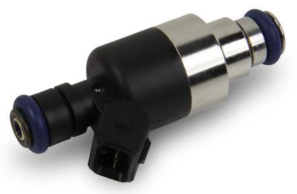

48 Injector Connectors There are three variations of LS injector connectors: EV1 Service item #


49 EV6 / USCAR Service item # MULTEC 2 Service item #


50 APPENDIX 3.0 THROTTLE BODIES AND PEDALS There are two styles of DBW throttle body connectors. The following part numbers are supported by Holley Terminator MPFI kits: 6 PIN CONECTOR: Service item # Service item # o Corvette, CTS-V and GTO o VIN Codes: E, U, W, Y o Engine Codes: L76, LQ4 (car), LS2, LS3, LS o Truck o VIN Codes: 0, 3, 4, 5, 8, C, H, J, K, L, M, Y o Engine Codes: L76, L92, LC9, LFA, LH6, LMF, LMG, LS2, LY2, LY5, LY o Corvette, Camaro, G8 o VIN Codes: E, J, W, Y o Engine Codes: L76, L99, LS3, LS o Truck o VIN Codes: 0, 2, 3, 4, 5, 7, 8, A, B, C, F, G, H, J, K, L, M, P, Y o Engine Codes: L20, L76, L92, L94, L96, L9H, LC8, LC9, LFA, LH6, LH8, LH9, LMF, LMG, LS2, LY2, LY5, LY6, LZ o 2001 thru 2005 Corvette & CTS-V o VIN Codes: G,S o Engine Codes: LS1, LS6 50


51 8 PIN (EARLY TRUCK) CONNECTOR: o Truck o VIN Codes: B, N, P, T, U, V, Z o Engine Codes: L33, L59, LM4, LM7, LQ4 (truck), LQ9, LR4 Throttle Pedal Holley recommends GM P/N which is a passenger car pedal with a 6 pin connector. APPENDIX 4.0 SENSOR DIAGNOSTICS AND STATUSES Sensor diagnostics are included in the handheld. If one of the main sensors has some type of error, a small, blinking red circle will appear in the upper right of the screen. To navigate to the diagnostics, select MONITOR and DIAGNOSTICS. If there is an issue an error will also be shown on any of the MONITOR or GAUGES screens. Wideband Oxygen Sensor Status Shows status of wideband oxygen sensors. Text Init.. Heating Cold! Hot! Unplgd Description Signifies that sensor channel is not enabled. First shown for an instant when the system is powered on. Displayed so quickly you will likely not see this. Sensor is heating. Sensor is below calibrated operating temperature. Unit will still read but accuracy may be impacted. Sensor is above calibrated operating temperature. Unit will still read but accuracy may be impacted. Sensor is unplugged. General Sensor Status These are shown for the coolant and air temperature, MAP, TPS, Oil and Fuel pressure sensors. If you do not have an oil or fuel pressure sensor installed, you will see this error. It will not cause a problem. Text Undefnd LOW Err HI Err Description Unlikely failure indicated that a sensor is not properly defined. A sensor displaying this can be unplugged, have an open or short circuit, or be otherwise damaged. A sensor displaying this can be unplugged, have an open or short circuit, or be otherwise damaged. 51
52 RPM (Crank Signal Inputs) Diagnostics The following are shown for the RPM parameter which indicates the status of the crank sensor/engine speed input. Text Stall! Syncng Nothing Error! Description No RPM input detected. Signal detected. Position being established. Will show briefly after crank signal and cam/crank positions established. Actual engine RPM will then be indicated. Cam/Crank input error detected. TPS Diagnostics The following are shown for the TPS parameter. Text Error! NeedCal Description If you see an error, contact Holley Tech Service. TPS Autoset needs to be performed. Closed Loop Diagnostics Shows status of closed loop operation. Text OpenLp CloseLp Description System is in open loop operation. System is in closed loop operation. Learn Status Shows status of learn mode. Text NoLearn Learng Description Learning is not active. Learn is in an active state. Switched Inputs/Outputs Status Shows status of switched inputs and outputs. Text OFF ON Description Input or Output is not active. Input or Output is active. 52
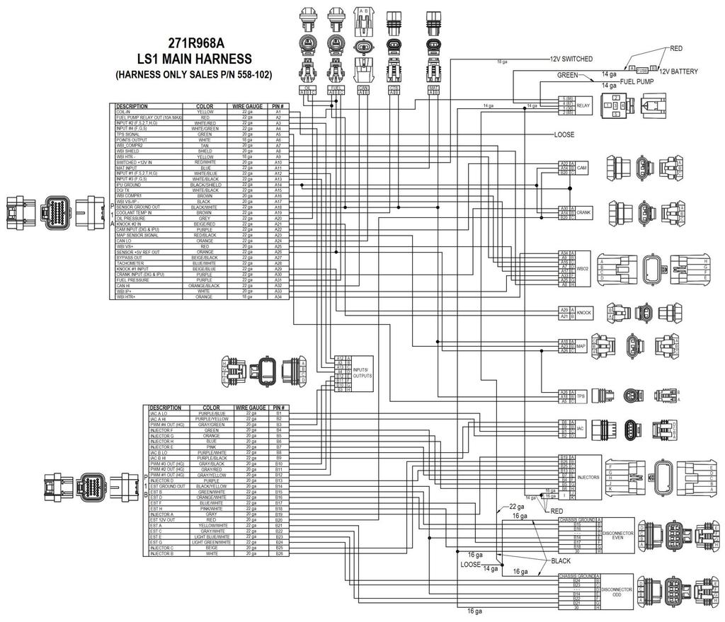
53 53
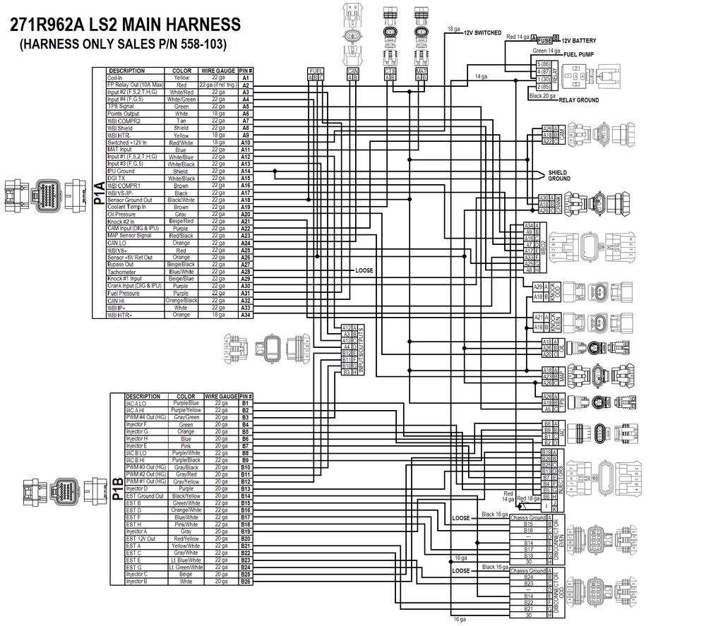
54 54
55 271R1101A EARLY TRUCK DRIVE-BY-WIRE HARNESS 55

56 Holley Technical Support: Holley Performance Products, Inc. All rights reserved. 199R10762 Revision Date:
EFI HARNESS KIT , & Kit Contents: Power Harness : All Kits
 EFI HARNESS KIT 558-500, 558-501 & 558-502 Kit Contents: Main Harness 558-102: Kits 558-500 558-103: Kits 558-501 & 502 Power Harness 558-308: All Kits Injector Harness 558-200: Kits 558-500 & 502 558-201:
4 BBL THROTTLE BODY FUEL INJECTION MASTER KIT
 4 BBL THROTTLE BODY FUEL INJECTION MASTER KIT 550-405K 950 CFM Polished Aluminum Throttle Body + Complete Fuel System 550-406K 950 CFM Hard Core Gray Throttle Body + Complete Fuel System FUEL INJECTION
WIRING MANUAL & DIAGRAMS 199R10555
 WIRING MANUAL & DIAGRAMS 199R10555 HP EFI and Dominator EFI Systems Contents 1.0 Manual Overview... 2 1 1.1 Important Wiring Do s and Don ts... 3 2.0 ECU Installation, Connectors, and Pinout... 3 2.1 Pinout...
4 BBL THROTTLE BODY FUEL INJECTION SYSTEM
 4 BBL THROTTLE BODY FUEL INJECTION SYSTEM 550-405 950 CFM 200-600 HP Polished Aluminum 550-406 950 CFM 200-600 HP Hard Core Gray INSTALLATION MANUAL 199R10653 NOTE: These instructions must be read and
QUICK START GUIDE 199R10546
 QUICK START GUIDE 199R10546 1.0 Overview This contains detailed information on how to use Holley EFI software and perform tuning that is included within the software itself. Once you load the software,
AVENGER EFI 4 BBL TBI SYSTEMS
 AVENGER EFI 4 BBL TBI SYSTEMS 550-400 (700 CFM 65 lb/hr injectors) up to 400 HP 550-401 (900 CFM 75 lb/hr injectors) up to 525 HP 550-402 (900 CFM 85 lb/hr injectors) up to 600 HP TBI HARDWARE INSTALLATION
QUICKSTART MANUAL SNIPER EFI INSTALLATION INSTRUCTIONS
 550-510, 550-511, & 550-516 QUICKSTART MANUAL SNIPER EFI INSTALLATION INSTRUCTIONS Congratulations on your purchase of a new Sniper EFI Throttle Body System built by craftsmen to exacting standards in
HP EFI UNIVERSAL RETROFIT KITS
 HP EFI UNIVERSAL RETROFIT KITS 550-500 (HP Universal Retrofit Kit for 4150 carb style intakes) 550-501 (HP Universal Retrofit Kit for 4500 carb style intakes) INSTALLATION INSTRUCTIONS 199R10510 NOTE:
HP EFI 4 BBL TBI SYSTEMS
 HP EFI 4 BBL TBI SYSTEMS 550-411 (900 CFM 75 lb/hr injectors) up to 525 HP 550-412 (900 CFM 85 lb/hr injectors) up to 600 HP NOTE: HP throttle body systems do not include fuel pump. TBI HARDWARE INSTALLATION
AVENGER EFI 4 BBL MPFI SYSTEMS
 AVENGER EFI 4 BBL MPFI SYSTEMS SINGLE PLANE 4BBL SMALL BLOCK CHEVY MULTI-PORT EFI SYSTEMS 550-811 (Early/Late Models) 550-816 (Vortec Heads) SINGLE PLANE 4BBL BIG BLOCK CHEVY MULTI-PORT EFI SYSTEMS 550-831
MPFI FUEL INJECTION SYSTEM
 MPFI FUEL INJECTION SYSTEM PART NUMBERS 550-903 thru 905, 550-916 thru 918 & 550-926 thru 931 HANDHELD TUNING AND REFERENCE MANUAL 199R11761 1 CONTENTS Tuning... 4 Basic... 4 Basic Fuel... 4 Closed Loop
StealthRam Small Block Chevy Multi-Port EFI Systems Standard and Vortec Intake Versions
 StealthRam Small Block Chevy Multi-Port EFI Systems Standard and Vortec Intake Versions 550-821 (Early/Late Heads) 550-822 (Early/Late Heads) Polished 550-826 (Vortec Heads) 550-827 (Vortec Heads) Polished
QUICKSTART MANUAL SNIPER EFI INSTALLATION INSTRUCTIONS
 8 Injector 4150 Super Sniper EFI (550-512 Shiny, 550-513 Black, & 550-517 Gold) 4 Injector 4150 Super Sniper EFI (550-518 Shiny, 550-519 Black, & 550-520 Gold) QUICKSTART MANUAL SNIPER EFI INSTALLATION
StealthRam Small Block Chevy Multi-Port EFI Systems Standard and Vortec Intake Versions
 StealthRam Small Block Chevy Multi-Port EFI Systems Standard and Vortec Intake Versions 550-820 (Early/Late Heads) 550-823 (Early/Late Heads) Polished 550-828 (Vortec Heads) Polished NOTE: Fuel pump and
INSTALLATION INSTRUCTIONS. Revision 3.1.1
 INSTALLATION INSTRUCTIONS Revision 3.1.1 Table of Contents INTRODUCTION... 4 INSTALLATION OVERVIEW... 5 Included Parts... 6 DEVICE WIRING... 7 Required Parts... 7 Guidelines... 7 Wiring Diagram... 8 Compatible
FUEL KITS P/N & 526-4
 FUEL KITS P/N 526-3 & 526-4 NOTE: These instructions must be read and fully understood before beginning installation. If this manual is not fully understood, installation should not be attempted. Failure
8 Injector 4150 Super Sniper EFI ( Shiny, Black, & Gold) 4 Injector 4150 Super Sniper EFI ( Shiny, Black, &
 4 Injector 4150 Super Sniper EFI ( Shiny, Black, &") 8 Injector 4150 Super Sniper EFI (550-512 Shiny, 550-513 Black, & 550-517 Gold) 4 Injector 4150 Super Sniper EFI (550-518 Shiny, 550-519 Black, & 550-520 Gold) 1 Holley Sniper EFI FUEL INJECTION INSTALLATION
8 Injector 4150 Super Sniper EFI (550-512 Shiny, 550-513 Black, & 550-517 Gold) 4 Injector 4150 Super Sniper EFI (550-518 Shiny, 550-519 Black, & 550-520 Gold) 1 Holley Sniper EFI FUEL INJECTION INSTALLATION
FUEL KITS P/N & 526-2
 FUEL KITS P/N 526-1 & 526-2 NOTE: These instructions must be read and fully understood before beginning installation. If this manual is not fully understood, installation should not be attempted. Failure
MALLORY FIRESTORM CD MULTI COIL HARDWARE INSTALLATION - PN 69050S / 69050R
 FORM 69050S/R MALLORY FIRESTORM CD MULTI COIL HARDWARE INSTALLATION - PN 69050S / 69050R To ensure you are using the most current instruction sheet, please visit www.malloryfirestorm.com. CAUTION! The
MegaSquirt III for LS Style Engines. Hardware Install. 1. Disconnect and remove the battery from the vehicle.
 MegaSquirt III for LS Style Engines MegaSquirt controllers are experimental devices intended for educational purposes. MegaSquirt controllers are not for sale or use on pollution controlled vehicles. Check
, & REFERENCE MANUAL
 550-510, 550-511 & 550-516 REFERENCE MANUAL Contents PARTS IDENTIFICATION... 2 MASTER KIT FUEL SYSTEM INSTALLATION... 4 GENERAL WIRING REFERENCE... 9 SYSTEM WIRING OVERVIEW... 12 IGNITION WIRING... 13
MegaSquirt III for Gen 3 HEMI. Hardware Install THE FOLLOWING SENSOR PART NUMBERS APPLY TO ALL HARNESSES FOR ENGINES 2004 TO CURRENT:
 MegaSquirt III for Gen 3 HEMI MegaSquirt controllers are experimental devices intended for educational purposes. MegaSquirt controllers are not for sale or use on pollution controlled vehicles. Check the
Ford Coyote Non-VVT Main Harness PN
 Ford Coyote Non-VVT Main Harness PN 558-114 This wiring harness interfaces a Holley EFI ECU to a Ford Coyote engine that has had the cam VVT hardware locked out. It is meant to be used in conjunction with
MALLORY FIRESTORM CD MULTI COIL HARDWARE INSTALLATION - PN 69150C / 69150R
 FORM 69150C/R MALLORY FIRESTORM CD MULTI COIL HARDWARE INSTALLATION - PN 69150C / 69150R To ensure you are using the most current instruction sheet, please visit www.malloryfirestorm.com. CAUTION! The
Ford Coyote Main Harness and Harness Kit PN , , and
 Ford Coyote Main Harness and Harness Kit PN 558-110, 550-619, and 550-625 This wiring harness interfaces a Holley EFI ECU to a Ford Coyote engine that has either had the cam VVT hardware locked out or
Summit Racing MAX-efi500
 Not legal for sale or use on pollution controlled vehicles Installation and Adjustment Instructions for Summit Racing MAX-efi500 Throttle Body System P/N SUM-240500 Please read the full instructions before
Gen III HEMI Harness PN or
 Gen III HEMI Harness PN 558-106 or 558-107 This wiring harness interfaces a Holley EFI ECU to a Gen III HEMI engine. It is meant to be used in conjunction with an injector harness, a coil harness, and
Installation Instructions for: EMS P/N and U Honda S2000
 Installation Instructions for: EMS P/N 30-1052 and 30-1052U 00-04 Honda S2000! WARNING: This installation is not for the tuning novice nor the PC illiterate! Use this system with EXTREME caution! The AEM
DOMINATOR FUEL PUMPS P/N & Installation Instructions 199R10573
 DOMINATOR FUEL PUMPS P/N 12-1400 & 12-1800 Installation Instructions 199R10573 WARNING! THESE INSTRUCTIONS MUST BE READ AND FULLY UNDERSTOOD BEFORE BEGINNING INSTALLATION. FAILURE TO FOLLOW THESE INSTRUCTIONS
Quadrajet Sniper EFI ( Shiny, Black, & Gold)
") Quadrajet Sniper EFI (550-867 Shiny, 550-868 Black, & 550-869 Gold) 1 Holley Sniper EFI FUEL INJECTION INSTALLATION MANUAL WARNING! Read this manual before using this product. This instruction manual must
Quadrajet Sniper EFI (550-867 Shiny, 550-868 Black, & 550-869 Gold) 1 Holley Sniper EFI FUEL INJECTION INSTALLATION MANUAL WARNING! Read this manual before using this product. This instruction manual must
CAUTION: CAREFULLY READ INSTRUCTIONS BEFORE PROCEEDING. NOT LEGAL FOR USE OR SALE ON POLLUTION CONTROLLED VEHICLES.
 Twin Tec Installation Instructions for VRFI D Version Fuel Injection Controller CAUTION: CAREFULLY READ INSTRUCTIONS BEFORE PROCEEDING. T LEGAL FOR USE OR SALE ON POLLUTION CONTROLLED VEHICLES. OVERVIEW
4150 Sniper EFI ( Shiny, Black, & Gold)
") 4150 Sniper EFI (550-510 Shiny, 550-511 Black, & 550-516 Gold) 1 Holley Sniper EFI FUEL INJECTION INSTALLATION MANUAL WARNING! Read this manual before using this product. This instruction manual must be
4150 Sniper EFI (550-510 Shiny, 550-511 Black, & 550-516 Gold) 1 Holley Sniper EFI FUEL INJECTION INSTALLATION MANUAL WARNING! Read this manual before using this product. This instruction manual must be
MS3-Pro LSx Drop On Harness
 24x MS3-Pro LSx Drop On Harness For engines with 24X crank triggers Thank you for buying our drop on wiring harness! We have designed this harness to support anything from a stock motor swapped into a
HP FUEL PUMPS P/N & Installation Instructions 199R10569
 HP FUEL PUMPS P/N 12-700 & 12-890 Installation Instructions 199R10569 WARNING! THESE INSTRUCTIONS MUST BE READ AND FULLY UNDERSTOOD BEFORE BEGINNING INSTALLATION. FAILURE TO FOLLOW THESE INSTRUCTIONS MAY
CAUTION: CAREFULLY READ INSTRUCTIONS BEFORE PROCEEDING
 Daytona Sensors LLC Engine Controls and Instrumentation Systems Installation Instructions for Wide-Band Exhaust Gas Oxygen Sensor Interface CAUTION: CAREFULLY READ INSTRUCTIONS BEFORE PROCEEDING OVERVIEW
HOLLEY VR2 FUEL PUMPS P/N & Installation Instructions 199R10975
 HOLLEY VR2 FUEL PUMPS P/N 12-3000 & 12-3000-2 Installation Instructions 199R10975 WARNING! THESE INSTRUCTIONS MUST BE READ AND FULLY UNDERSTOOD BEFORE BEGINNING INSTALLATION. FAILURE TO FOLLOW THESE INSTRUCTIONS
DISTRIBUTORLESS IGNITION SYSTEM Installation and Adjustment Instructions
 DISTRIBUTORLESS IGNITION SYSTEM Installation and Adjustment Instructions 1.0 INTRODUCTION: Congratulations on your purchase of a Holley Distributorless Ignition System! Holley cannot and will not be responsible
HOWELL INSTALLATION MANUAL. Tuned Port Or LT-1 Fuel Injection Harness ( )
") HOWELL ENGINE DEVELOPMENTS, INC. FUEL INJECTION APPLICATIONS INSTALLATION MANUAL Tuned Port Or LT-1 Fuel Injection Harness (1985-1992) Howell Engine Developments, Inc. 6201 Industrial Way Marine City,
HOWELL ENGINE DEVELOPMENTS, INC. FUEL INJECTION APPLICATIONS INSTALLATION MANUAL Tuned Port Or LT-1 Fuel Injection Harness (1985-1992) Howell Engine Developments, Inc. 6201 Industrial Way Marine City,
ELITE 1000/1500 Dodge SRT QUICK START GUIDE HT
 E N G I N E M A N A G E M E N T S Y S T E M S ELITE 1000/1500 Dodge SRT4 03-05 QUICK START GUIDE HT-140940 LIMITED WARRANTY Lockin Pty Ltd trading as Haltech warrants the HaltechTM Programmable Fuel Injection
Adaptronic esel020 Select ECU for Nissan S13 240SX (KA24DE) / RNN14 GTiR / SR20VE
 / RNN14 GTiR / SR20VE") 1 P a g e Adaptronic esel020 Select ECU for Nissan S13 240SX (KA24DE) / RNN14 GTiR / SR20VE Applicable vehicles / engines: Nissan S13 KA24DE 240SX US Market Nissan N14 SR20DET / SR20VE - Pulsar GTi-R /
1 P a g e Adaptronic esel020 Select ECU for Nissan S13 240SX (KA24DE) / RNN14 GTiR / SR20VE Applicable vehicles / engines: Nissan S13 KA24DE 240SX US Market Nissan N14 SR20DET / SR20VE - Pulsar GTi-R /
Speed-Pro EFI Installation Manual
 Speed-Pro EFI Installation Manual Speed-Pro Electronics Installation Manual Page The wiring harness is labeled on each of the connectors to simplify installation. Your application may not require the use
CAUTION: CAREFULLY READ INSTRUCTIONS BEFORE PROCEEDING
 Daytona Sensors LLC Engine Controls and Instrumentation Systems Installation Instructions for WEGO II Wide-Band Exhaust Gas Oxygen Sensor Interface Methanol Version CAUTION: CAREFULLY READ INSTRUCTIONS
GENERAL ANDROID DEVICE RECOMMENDATIONS
 GENERAL ANDROID DEVICE RECOMMENDATIONS The Edelbrock EFI E-Tuner app is compatible with most Android based Smartphones and tablets operating on Android 5.0 and later. However, due to slight variations
Controller Ground (dual black 12awg) should be connected to chassis ground as close as possible to the battery.
 should be connected to chassis ground as close as possible to the battery.") 1. Overview The Maximizer 4 progressive nitrous controller operates one or two separate stages of nitrous based on either time, RPM, MPH, throttle percentage or boost pressure. Whether your engine is naturally
1. Overview The Maximizer 4 progressive nitrous controller operates one or two separate stages of nitrous based on either time, RPM, MPH, throttle percentage or boost pressure. Whether your engine is naturally
INSTALLATION TUNING AND TROUBLESHOOTING MANUAL
 Part Number 501-12 Pro-Jection 1D, 300 CFM INSTALLATION TUNING AND TROUBLESHOOTING MANUAL These instructions must be read and fully understood before beginning installation. If this manual is not fully
HP FUEL PUMPS P/N ERL & ERL Installation Instructions 199R11108
 HP FUEL PUMPS P/N 1200600ERL & 1200890ERL Installation Instructions 199R11108 WARNING! THESE INSTRUCTIONS MUST BE READ AND FULLY UNDERSTOOD BEFORE BEGINNING INSTALLATION. FAILURE TO FOLLOW THESE INSTRUCTIONS
GENERAL MOTORS SERVICE PARTS OPERATION 6200 Grand Pointe Drive, Grand Blanc, MI 48439
 LS IGNITION CONTROLLER 19355418 Ignition Control for Carbureted LS Series Engines (24x Crankshaft Index/1x Camshaft Index, 58x Crankshaft Index/4x Camshaft Index) Parts Included Quantity Ignition Controller
Powertrain DTC Summaries EOBD
 Powertrain DTC Summaries Quick Reference Diagnostic Guide Jaguar X-TYPE 2.0 L 2002.25 Model Year Refer to page 2 for important information regarding the use of Powertrain DTC Summaries. Jaguar X-TYPE 2.0
Table of Contents. 4 Getting Started 4 About the Juice 5 Safety Terms 5 Product Registration 6 Important Notes 7 Truck Orientation
 Table of Contents 4 Getting Started 4 About the Juice 5 Safety Terms 5 Product Registration 6 Important Notes 7 Truck Orientation 8 Juice Installation 1999-2003 (7.3L) 8 Supplied Items & Required Tools
Fuel Metering System Component Description
 1999 Chevrolet/Geo Tahoe - 4WD Fuel Metering System Component Description Purpose The function of the fuel metering system is to deliver the correct amount of fuel to the engine under all operating conditions.
Ford Racing 4.6L 3V Crate Engine Control Pack
 Ford Racing 4.6L 3V Crate Engine Control Pack Installation Time: 3-6 hours on a Foxbody Mustang Tools Required: Basic English and Metric Socket and Wrench Set Flat and Phillips Screwdrivers Torx bits Hammer
4. Remove distributor hold-down. Lift the distributor upwards and remove.
 Holley Sniper EFI HyperSpark Distributors are designed to plug and play with Sniper EFI systems. This design includes a single Hall Effect sensor providing crankshaft speed to the ECU. The precision machined
Installation Instructions for: EMS P/N Ford Mustang 5.0L
 Installation Instructions for: EMS P/N 30-1401 1994-95 Ford Mustang 5.0L! WARNING: This installation is not for the tuning novice nor the PC illiterate! Use this system with EXTREME caution! The AEM EMS
2002 ENGINE PERFORMANCE. Self-Diagnostics - RAV4. Before performing testing procedures, check for any related Technical Service Bulletins (TSBs).
.") 2002 ENGINE PERFORMANCE Self-Diagnostics - RAV4 INTRODUCTION NOTE: Before performing testing procedures, check for any related Technical Service Bulletins (TSBs). To properly diagnosis and repair this
2002 ENGINE PERFORMANCE Self-Diagnostics - RAV4 INTRODUCTION NOTE: Before performing testing procedures, check for any related Technical Service Bulletins (TSBs). To properly diagnosis and repair this
PLUG & PLAY. Quick Start Guide. GM LS 58X Drop On Harness. MS3Pro ULTIMATE
 Quick Start Guide PLUG & PLAY GM LS 58X Drop On Harness MS3Pro ULTIMATE For GM LS Engines with 58X Crank Triggers Thank you for your purchase and support for American made products! We have designed this
Installation Instructions for: EMS P/N Ford Mustang 5.0L
 Installation Instructions for: EMS P/N 30-1400 1986-93 Ford Mustang 5.0L! WARNING: This installation is not for the tuning novice nor the PC illiterate! Use this system with EXTREME caution! The AEM EMS
BigStuff3 - GEN3. 1st Gear Spark Retard with Spark Retard Traction Control System (SR 2 ) Rev
 Rev") BigStuff3 - GEN3 1st Gear Spark Retard with Spark Retard Traction Control System (SR 2 ) 12-09 System Description 1st Gear Spark Retard with Spark Retard Traction Control System (SR 2 ) - SR 2 uses two
BigStuff3 - GEN3 1st Gear Spark Retard with Spark Retard Traction Control System (SR 2 ) 12-09 System Description 1st Gear Spark Retard with Spark Retard Traction Control System (SR 2 ) - SR 2 uses two
Direct Link Basic Tuning Guide (Delphi)
") Direct Link Basic Tuning Guide (Delphi) This Guide is intended to answer basic Direct Link tuning questions and to act as a Quick Start Guide. It is not intended to be the Gospel on the tuning process
Direct Link Basic Tuning Guide (Delphi) This Guide is intended to answer basic Direct Link tuning questions and to act as a Quick Start Guide. It is not intended to be the Gospel on the tuning process
HP and Dominator Component Selection Guide. Use when building Dominator Systems or Custom HP Systems. Step 2 (notes) Choose Your Main Harness
 Choose Your Main Harness") HP and Dominator Component Selection Guide Use when building Dominator Systems or Custom HP Systems Step 1 (required) Choose your ECU & Main Power Harness Step 2 (notes) Choose Your Main Harness Step 3
HP and Dominator Component Selection Guide Use when building Dominator Systems or Custom HP Systems Step 1 (required) Choose your ECU & Main Power Harness Step 2 (notes) Choose Your Main Harness Step 3
Getting to know your Powertrain Control Module (PCM)
") Thank-you for choosing Swap Specialties and Performance for your LS project needs. Expect everything to be the highest of quality, craftsmanship, and detail. Every product is 100% tested. Please follow
Thank-you for choosing Swap Specialties and Performance for your LS project needs. Expect everything to be the highest of quality, craftsmanship, and detail. Every product is 100% tested. Please follow
INSTALLATION INSTRUCTIONS. Revision 4.0.3
 INSTALLATION INSTRUCTIONS Revision 4.0.3 Table of Contents INTRODUCTION... 3 INSTALLATION OVERVIEW... 4 Included Parts... 5 DEVICE WIRING... 6 Required Parts... 6 Guidelines... 6 Wiring Diagram... 7 Engine
Table Of Contents TABLE OF CONTENTS INTRODUCTION INSTALLATION OPERATING INSTRUCTIONS APPENDIX ABOUT THE JUICE... 3 SAFETY TERMS...3 INTRODUCTION...
 Ford Juice installation Instructions **read important safety information in this manual** TABLE OF CONTENTS F o r d J u i c e Table Of Contents ABOUT THE JUICE... 3 SAFETY TERMS...3 INTRODUCTION... 3 PRODUCT
FUEL INJECTION SYSTEM - MULTI-POINT
 FUEL INJECTION SYSTEM - MULTI-POINT 1988 Jeep Cherokee 1988 Electronic Fuel Injection JEEP MULTI-POINT 4.0L Cherokee, Comanche, Wagoneer DESCRIPTION The Multi-Point Electronic Fuel Injection (EFI) system
G - TESTS W/CODES - 2.2L
 G - TESTS W/CODES - 2.2L 1994 Toyota Celica 1994 ENGINE PERFORMANCE Toyota 2.2L Self-Diagnostics Celica INTRODUCTION If no faults were found while performing F - BASIC TESTING, proceed with self-diagnostics.
Instruction Manual. Fuel Injection. for the following Go EFI Systems Go Street EFI System Easy-Street EFI System Kit Contents
 This Quick Start Manual is designed to get you up and running with the Go Street Kit and either the 40003 Fuel Command Center or the 40005 Inline Fuel Delivery Kit. The FiTech Go EFI System is the industry's
HOWELL INSTALLATION MANUAL. Throttle Body Fuel Injection Harness
 HOWELL ENGINE DEVELOPMENTS, INC. FUEL INJECTION APPLICATIONS INSTALLATION MANUAL Throttle Body Fuel Injection Harness Howell Engine Developments, Inc. 6201 Industrial Way Marine City, MI 48039 Phone: 810-765-5100
MSD 6LS-2 Ignition Controller for Carbureted and EFI LS 2/LS 7 Engines PN 6012
 MSD 6LS-2 Ignition Controller for Carbureted and EFI LS 2/LS 7 Engines PN 6012 ONLINE PRODUCT REGISTRATION: Register your MSD product online. Registering your product will help if there is ever a warranty
Programmable 8 Channel Injector Driver Module
 Overview: Programmable 8 Channel Injector Driver Module 554-142 The 8 channel fuel injector driver module allows for an input signal from any ECU to be changed into a user selectable peak and hold current.
Installation Instructions Diesel Nitrous System (#82028)
") Installation Instructions Diesel Nitrous System (#82028) Thank you for choosing ZEX. If at any time you have questions regarding this or any of our products, please call our Nitrous Help support line at
Installation Instructions Diesel Nitrous System (#82028) Thank you for choosing ZEX. If at any time you have questions regarding this or any of our products, please call our Nitrous Help support line at
IT S ELECTRIC SWITCHING TO HOLLEY EFI YIELDS BETTER DRIVABILITY AND MORE POWER FOR A BOOSTED 68 FIREBIRD
 WORDS: Scott Parker PICTURES: By Redline Motorsports IT S ELECTRIC SWITCHING TO HOLLEY EFI YIELDS BETTER DRIVABILITY AND MORE POWER FOR A BOOSTED 68 FIREBIRD I t s been said many times, and often it has
CAUTION: CAREFULLY READ INSTRUCTIONS BEFORE PROCEEDING
 Daytona Sensors LLC Engine Controls and Instrumentation Systems Installation Instructions for WEGO IIID Wide-Band Exhaust Gas Oxygen Sensor Interface (Automotive Version) CAUTION: CAREFULLY READ INSTRUCTIONS
CAUTION: CAREFULLY READ INSTRUCTIONS BEFORE PROCEEDING
 Daytona Sensors LLC Engine Controls and Instrumentation Systems Installation Instructions for Wide-Band Exhaust Gas Oxygen Sensor Interface CAUTION: CAREFULLY READ INSTRUCTIONS BEFORE PROCEEDING OVERVIEW
Powertrain DTC Summaries OBD II
 Powertrain DTC Summaries Quick Reference Diagnostic Guide Jaguar X-TYPE 2.5L and 3.0L 2002 Model Year Revised January, 2002: P0706, P0731, P0732, P0733, P0734, P0735, P0740, P1780 POSSIBLE CAUSES Revised
LSx Harness Installation. lsxeverything.com #BecauseYouShould
 LSx Harness Installation lsxeverything.com #BecauseYouShould Table of Contents Slide 1 Introduction Page Slide 2 Table of Contents Slide 3 Starting Instructions Slide 4 Power Connections Slide 5 Ground
1. Index. LS Wiring Harness. 2. Presentation Warnings and Warranty Terms Overview Labels...7
 OWNER S MANUAL 1. Index 2. Presentation...4 3. Warnings and Warranty Terms...5 4. Overview...6 5. Labels...7 6. Diagrams...7 6.1 FT500/FT500 Aux - Inputs/outputs...7 6.2 Nano WB O2 #1...8 6.3 Nano WB
MaxxECU quickstart guide ( )
") Be a tuning mastermind. Like us. MaxxECU quickstart guide (2019-02-01) Online help! maxxecu.com/support Wiring diagrams Installation help Pinout Support maxxecu.com/support Legal disclaimer All performance
Be a tuning mastermind. Like us. MaxxECU quickstart guide (2019-02-01) Online help! maxxecu.com/support Wiring diagrams Installation help Pinout Support maxxecu.com/support Legal disclaimer All performance
Operating and Installation Instructions
 Model Number 40401-c (-sp) Electronic Fuel Pump Operating and Installation Instructions This Product is Patent Pending. Application available upon request CAUTION! This product is to be installed only
FAST Ethanol-Methanol Air/Fuel Meter
 INSTRUCTIONS Ethanol-Methanol Air/Fuel Meter Thank you for choosing products; we are proud to be your manufacturer of choice. Please read this instruction sheet carefully before beginning installation,
Property of American Airlines
 Gen. II Ford 300 Install 1775 N. Lapeer Rd. Unit B Oxford, MI 48371 248-393-1621 TABLE OF CONTENTS 1. Kit Contents....3 2. Installation Instructions.. 4 3. Component Description.....10 4. Final Checks....12
Part #82064 Add-A-Stage EFI Nitrous System
 1 INSTRUCTIONS Part #82064 Add-A-Stage EFI Nitrous System Thank you for choosing products; we are proud to be your manufacturer of choice. Please read this instruction sheet carefully before beginning
9415 W. Ridge Rd. Elsie, MI
 9415 W. Ridge Rd. Elsie, MI 48831 248-393-1621 989-862-4163 TBI INSTALLATION INSTRUCTIONS Congratulations on the purchase of your Affordable Fuel Injection TBI system. We are confident that this purchase
INSTALLATION GUIDE Table of Contents
 CT-3100 Automatic transmission remote engine starter systems. What s included..2 INSTALLATION GUIDE Table of Contents Door lock toggle mode..... 4 Notice...2 Installation points to remember. 2 Features..2
PIMP Ford 5.0 Harness Installation Manual. Part Number: PM-75
 PIMP Ford 5.0 Harness Installation Manual Part Number: PM-75 Ron Francis Wiring 200 Keystone Rd Suite 1 Chester, PA 19013 800-292-1940 www.ronfrancis.com Pre-Installation Notes: This system is designed
TELORVEK EFI 5.0 Coyote Sequential Fuel Injection System Part # CY-11
 Page #1 TELORVEK EFI 5.0 Coyote Sequential Fuel Injection System Part # CY-11 WIRING INSTRUCTIONS Thank you for purchasing the absolute finest of wiring kits for the Ford Motor Co. Coyote modular engine.
This product is legal in California for racing vehicles only and should never be used on public highways.
 Installation Instructions for: EMS P/N 30-1602 and 30-1602U 96-99 Nissan 180SX SR20DET 97-98 Nissan Silvia S14 SR20DET 93-98 Nissan Silvia S14 SR20DET (Europe) 99-02 Nissan Silvia S15 SR20DET! WARNING:
MSD LS-1/LS-6 Controller for Carbureted and EFI Gen III Engines PN 6010
 MSD LS-1/LS-6 Controller for Carbureted and EFI Gen III Engines PN 6010 Parts Included 1 Ignition Controller, PN 6010 1 Pro-Data+ Software CD 1 Harness 1 Parts Bag 6 Timing Modules Optional Accessories
Not required for most applications. Not required for most applications. High pressure ( provided) High pressure ( provided)
 High pressure ( provided)") ELECTRIC FUEL PUMPS P/N 12-801-1, 712-801-1, 12-802-1, 12-802-2, 712-802-1, 12-812, 12-815-1, & 712-815-1 FUEL PRESSURE REGULATORS P/N 12-500, 12-501, 12-803, 12-803BP, 12-804, & 15812NOS Installation
ELECTRIC FUEL PUMPS P/N 12-801-1, 712-801-1, 12-802-1, 12-802-2, 712-802-1, 12-812, 12-815-1, & 712-815-1 FUEL PRESSURE REGULATORS P/N 12-500, 12-501, 12-803, 12-803BP, 12-804, & 15812NOS Installation
TABLE OF CONTENTS. Please visit the Edelbrock Support Forum for the latest Pro-Flo 4 news and important updates:
 TABLE OF CONTENTS Introduction...1-2 Tools and System Requirements... 2 Fuel System Requirements... 3 Primary Kit Components (4150)... 4 Component Layout (4150)...5-6 Primary Kit Components (XT)... 7 Component
PLATINUM Series CAN WIDEBAND CONTROLLER WBC 1 & WBC 2 QUICK START GUIDE (HT & HT059980) Version 4
 Version 4") PLATINUM Series CAN WIDEBAND CONTROLLER WBC 1 & WBC 2 (HT059970 & HT059980) QUICK START GUIDE HALTECH HEAD OFFICE: PH: +612 9729 0999 FAX: +612 9729 0900 EMAIL: sales@haltech.com HALTECH US OFFICE: PH:
PLATINUM Series CAN WIDEBAND CONTROLLER WBC 1 & WBC 2 (HT059970 & HT059980) QUICK START GUIDE HALTECH HEAD OFFICE: PH: +612 9729 0999 FAX: +612 9729 0900 EMAIL: sales@haltech.com HALTECH US OFFICE: PH:
Installation Instructions for: EMS P/N Toyota Supra
 Installation Instructions for: EMS P/N 30-1110 1987-1988 Toyota Supra! WARNING: This installation is not for the tuning novice nor the PC illiterate! Use this system with EXTREME caution! The AEM EMS System
Lingenfelter NCC-002 Nitrous Control Center Quick Setup Guide
 Introduction: Lingenfelter NCC-002 Nitrous Control Center Quick Setup Guide The NCC-002 is capable of controlling two stages of progressive nitrous and fuel. If the NCC-002 is configured only for nitrous,
Vortec Drive by Cable Electronic Fuel Injection Wiring Harness (P/N HAR-1018) HAR-1018
 HAR-1018") 1998 2002 Vortec Drive by Cable Electronic Fuel Injection Wiring Harness (P/N HAR-1018) HAR-1018 PERFORMANCE SYSTEMS INTEGRATION 170 Oberlin Ave N Suite 13 Lakewood NJ 08701-4548 Ph: 732-444-3277 Email:
1998 2002 Vortec Drive by Cable Electronic Fuel Injection Wiring Harness (P/N HAR-1018) HAR-1018 PERFORMANCE SYSTEMS INTEGRATION 170 Oberlin Ave N Suite 13 Lakewood NJ 08701-4548 Ph: 732-444-3277 Email:
SLP Camaro ZL1 STAGE 3 (650 HP)
") SLP - 2012 Camaro ZL1 STAGE 3 (650 HP) PART #26002 PACKING LIST Before installation, use this check list to make sure all necessary parts have been included. ITEM QTY CHECK PART NUMBER DESCRIPTION 1. 1
SLP - 2012 Camaro ZL1 STAGE 3 (650 HP) PART #26002 PACKING LIST Before installation, use this check list to make sure all necessary parts have been included. ITEM QTY CHECK PART NUMBER DESCRIPTION 1. 1
MSD Stacker-4 (4-Channel), PN 7010 Stacker-8 (8-Channel), PN 7020
, PN 7010 Stacker-8 (8-Channel), PN 7020") INSTALLATION INSTRUCTIONS 1 MSD Stacker-4 (4-Channel), PN 7010 Stacker-8 (8-Channel), PN 7020 Important: Read these instructions before attempting this installation! Parts Included: 1 - MSD Stacker Ignition
INSTALLATION INSTRUCTIONS 1 MSD Stacker-4 (4-Channel), PN 7010 Stacker-8 (8-Channel), PN 7020 Important: Read these instructions before attempting this installation! Parts Included: 1 - MSD Stacker Ignition
Powertrain DTC Summaries EOBD
 Powertrain DTC Summaries Quick Reference Diagnostic Guide Jaguar S-TYPE V6, V8 N/A and V8 SC 2002.5 Model Year Refer to pages 2 9 for important information regarding the use of Powertrain DTC Summaries.
On all settings above 100 horsepower the following precautions should be observed:
 ELECTRONIC FUEL INJECTED 5.0 COYOTE PLATE SYSTEM INSTALLATION INSTRUCTIONS Congratulations on the purchase of your Nitrous Express Coyote Plate system. Nitrous Express utilizes only the highest quality
DI 3 ENGINE DIAGNOSTICS DI00H 22 PRE CHECK
 PRECHECK DI3 DI00H22 1. DIAGNOSIS SYSTEM (a) Description When troubleshooting OBD II vehicles, the only difference from the usual troubleshooting procedure is that you connect to the vehicle the OBD II
Installation Instructions for: EMS P/N Acura Integra Acura 2.3CL Honda Accord Honda Civic
 Installation Instructions for: EMS P/N 30-6050 00-01 Acura Integra 98-99 Acura 2.3CL 98-02 Honda Accord 99-00 Honda Civic Thank you for purchasing an AEM Engine Management System. The AEM Engine Management
Core Harness System Crank/Cam Adapter Harness FAST Dual Sync Distrubutor 35" STOP!
 Instruction Manual 30-3805-20 Core Harness System Crank/Cam Adapter Harness FAST Dual Sync Distrubutor 35" STOP! THIS PRODUCT HAS LEGAL RESTRICTIONS. READ THIS BEFORE INSTALLING/USING! THIS PRODUCT MAY
ITCEMS950 Idle Timer Controller - Engine Monitor Shutdown Isuzu NPR 6.0L Gasoline Engine
 Introduction An ISO 9001:2008 Registered Company ITCEMS950 Idle Timer Controller - Engine Monitor Shutdown 2014-2016 Isuzu NPR 6.0L Gasoline Engine Contact InterMotive for additional vehicle applications