MS3-Pro LSx Drop On Harness
|
|
|
- Kenneth Holmes
- 5 years ago
- Views:
Transcription
1 24x

2 MS3-Pro LSx Drop On Harness For engines with 24X crank triggers Thank you for buying our drop on wiring harness! We have designed this harness to support anything from a stock motor swapped into a vintage muscle car to serious drag cars. If you have any questions about the installation, please contact us at support@diyautotune.com. The harness has undergone a few revisions since its initial release. This install guide applies to our version 2 harness, which you can identify by the yellow bands applied to the body and the spare connections. Version 1 harnesses do not have these bands. Parts included The package includes the following items: MS3-Pro ECU USB thumb drive with software and instructions Complete wiring harness with fuse block and fuses included RS232 (DB9) serial tuning cable and DB9 to sealed 4 pin adapter USB tuning cable 6 pin gray connector for O2 sensor connections 6 pin black connector for transmission control or other expansion devices 15 crimp pins for above connectors 100 ohm resistor for alternator light installation Ground wire for fuel pump


3 The MS3-Pro will include a FULL TunerStudio registration with purchase. To register TunerStudio, you will need to go to this link and enter the serial number, found on a silver sticker on the underside of the ECU. The registration code is valid for one user with up to three tuning computers, and there is no limit to how many ECUs you may use with the registered version of TunerStudio. Applications This harness is designed to fit all engines in the LS family that used a 24X crank trigger, including Corvette, F-body, and truck engines. We offer three variations, based on the injector type. The harness has been cut so that it can accommodate both car and truck intake manifolds, as well as most aftermarket manifold options. You will need to use a cable operated throttle body with OEM style TPS and IAC connectors; non stock sensors or IAC valves may require minor changes. A few unusual intake manifolds (particularly carburetor style or independent runner designs) will need extending some of the wires to fit relocated components. Injector with EV1 connector Injector with truck (Multec) connector Injector with EV6 connector There are a few engine variations that may require minor changes. For example, a few truck engines used a one wire oil pressure sensor switch, located behind the intake manifold. Using the MS3-Pro's oil pressure input will require swapping to a three wire oil pressure sensor. Some alternator brackets (particularly aftermarket alternator relocation kits) may require extending the alternator connection. We have a plug in extension cable (part number MS3Ph-LSAlt) for the alternator connection if you want to extend this without any splicing or cuttting. Pre-installation considerations This harness is designed for installing the MS3-Pro and fuse block in the passenger compartment. These parts are capable of withstanding underhood heat if they are mounted at least 12" (30 cm) from the exhaust system. For unusually high vibration installations, use rubber vibration isolators to mount the ECU. The MS3-Pro is splash resistant but not intended to be kept underwater continuously. It can stop water from getting in for about 5 minutes, but after that, water can start seeping into the case. If you need continuous immersion resistance, you can seal the case with RTV silicone. We used high temperature wire for the harness, but you will want to avoid routing it too close to the exhaust system as well.
 sensor connectors.")


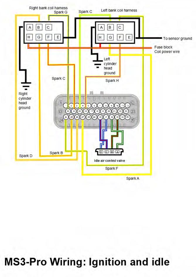
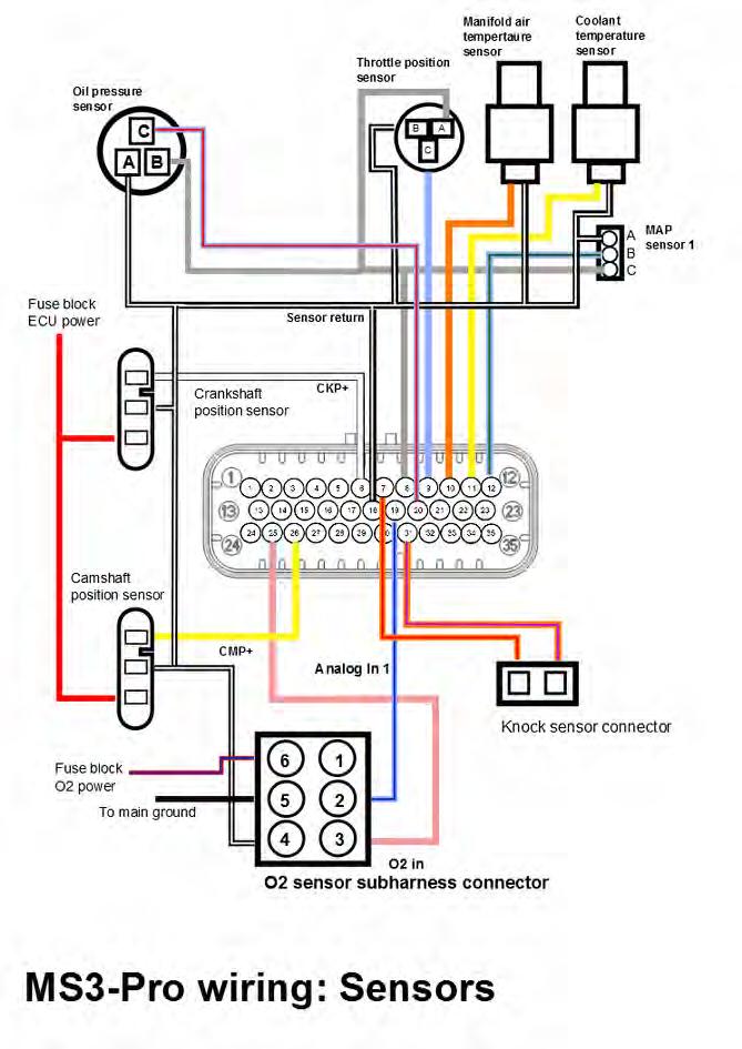
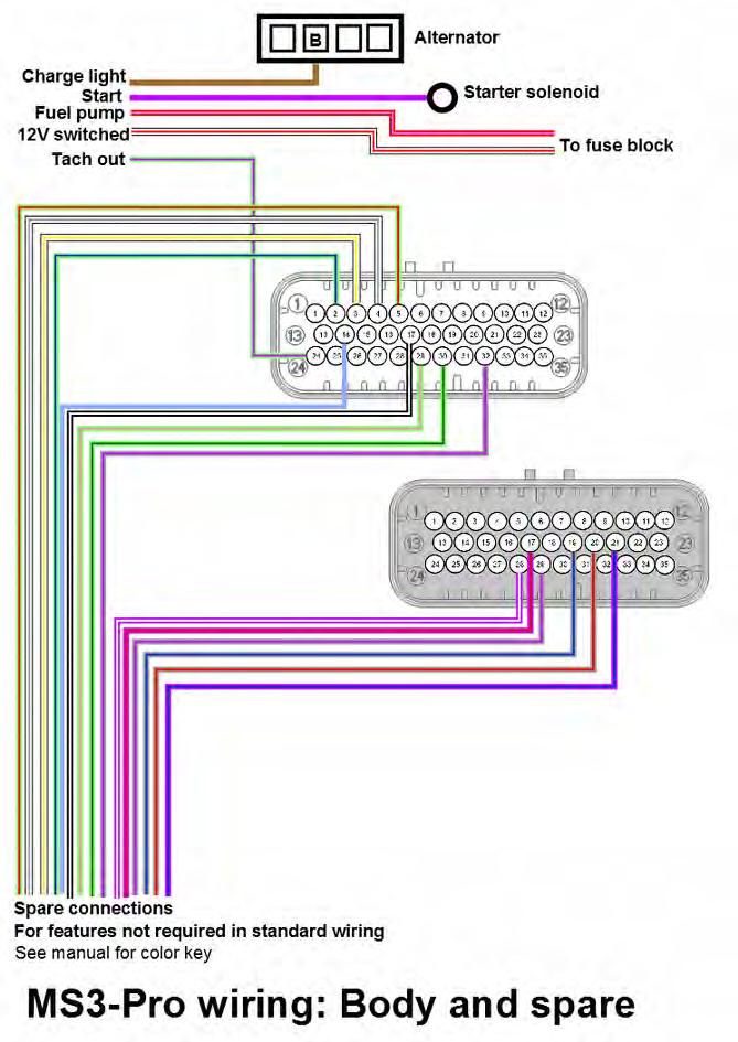
4 Installating the harness Body and spare connections Odd numbered cylinder branch Even numbered cylinder branch The harness is split into two branches on the engine, with the branches joining above the bellhousing. The even numbered cylinder section includes the crank sensor, right injector and coil banks, starter solenoid, and IAT (intake air temperature) sensor connectors. The odd numbered section includes connectors for the oil pressure sensor (connected to Analog In 2), knock sensor subharness, MAP sensor, cam position sensor, left injector and coil banks, alternator, coolant temperature sensor, throttle position sensor, and IAC valve. The branch marked "Body" contains critical connections to the vehicle electrical system. These wires are color coded. Purple: Starter solenoid power. Connect to starter relay. 14 gauge. Brown: Alternator light. The alternators on these motors use the same wire to supply a turn on signal and activate a warning light at low output. 20 gauge. White / Red: 12 volt switched power. 20 gauge. Purple / Red: Supplies 12 volts for the fuel pump. 10 gauge. Illustration 1: Body and spare connections Light green / Purple: Tach output signal. This supplies a tach signal to stock or aftermarket tachometers, and can also supply an RPM signal to other devices such as shift lights, fuel pump controllers, or anything else that can accept a tach signal. Output is a 0-12 volt square wave. Some factory tachometers may need a high voltage tach adapter. 20 gauge. Before installing the harness, check to be sure you have access to the rear of the engine. On some swaps, you may have an easier time installing the harness if you first unbolt the hood to improve accessibility. Step-by-step Wiring Directions: 1. Disconnect the battery.
. 3.")

5 2. Begin by cutting a hole in the firewall and feeding the harness through from the inside to the engine. Minimum recommended hole diameter for the wiring harness is 1.75" (45 mm). 3. Under the hood, start with the odd numbered cylinder branch of the harness, and position it along or under the injector fuel rail. Connect the IAC, TPS, coolant temperature, odd numbered injectors, left coil subharness, and alternator connections. If the alternator does not mount in the stock F-body or truck location high on the left side, you can splice and extend the alternator connection wire, or use our MS3Ph-LSAlt plug in extension.


6 4. No alternator charging wire is included with the harness due to the large number of possible battery locations. Connect the alternator output terminal lug to the battery positive terminal. Use a minimum of 4 gauge for a 150 amp alternator, 6 gauge for 100 gauge wire. For additional protection, we recommend installating a circuit breaker on this wire. 5. Next, you will attach the connections at the rear of the engine. Connect the knock subharness connector, cam position sensor, oil pressure sensor, and MAP sensor.


7 6. At the back of the engine, the harnesss also includes a ring terminal to ground the coils that connects to the bolt hole on the back of the cylinder head using an M10 x 1.5 mm bolt. Make sure the bolt is torqued down tightly and the ring terminal is not able to rotate when the bolt is tightened. Using a too-long bolt can result in a bad connection and intermittent sparks. 7. The harness also incorporates a single heavy gauge green wire that starts at its split point. This wire supplies 12 volt fused power which can be used to run a cooling fan or other ECU controlled device through a relay in the fuse box. The MS3-Pro drives this output through High Current Out Run the even numbered cylinder harness under or along the fuel rail. Connect the even numbered injector plugs and the right hand coil subharness plug. 9. Bolt the ring terminal at the front of the even numbered cylinder harness to the front of the cylinder head using a M10 x 1.5 mm bolt. Make sure the ring terminal is not able to rotate on the bolt.


 and starter relay wires. 13. Re-install the starter. 14.")
8 10. Connect the IAT sensor. If your engine does not have a provision for the IAT, you can either mount it using a bung in the charge pipe, or tap into a suitable location on the intake manifold and thread an IAT sensor into this. On many truck intake manifolds, the canister purge solenoid location is a good place to tap for the sensor. If you are using a metal intake manifold, we recommend mounting the IAT sensor in the charge pipe instead. 11. Support the front end of the vehicle on jackstands and remove the starter. Run the foil wrapped wire down to the vicinity of the starter. 12. Connect the crankshaft position (CKP) and starter relay wires. 13. Re-install the starter. 14. The branch with 4 gauge wire and the 20 gauge white wire connects to the battery or master disconnect switch. The red wire and the white both connect to the positive terminal, while the black wire connects to the negative terminal. Optionally, you can use a circuit breaker on the 4 gauge red wire. (125 to 150 amp circuit breaker recommended)

9 15. Next, you will connect the five wires on the Body harness. 16. Connect the solid purple starter wire to the vehicle's starter relay wire. This will trigger the starter solenoid. 17. Connect the brown alternator wire to the alternator warning light wire. We recommend putting a 100 ohm, 2 watt or greater resistor (included with the harness) in parallel with the alternator light to energize the alternator if the light fails. If the vehicle does not have an alternator warning light, connect to switched 12 volts through the supplied resistor. 18. Connect the white and red wire to a wire from the ignition key that receives 12 volt power with the key in both the Run and Start positions. 19. The purple and red wire supplies 12 volts to the fuel pump. Connect this wire to the fuel pump positive terminal. If you do not have a wire for the negative terminal, you can use the supplied fuel pump ground wire to connect the negative terminal to chassis ground. 20. Connect the light green and purple wire to the vehicle's tachometer signal wire, if so equipped. As this is a racing harness, it does not include all the connectors that come on an OEM wiring harness. You may have several devices on your engine that do not have a connector provided in our harness, including the following items: Mass air flow (MAF) sensor Clutch switch OBD2 diagnostic port Evaporative emission canister purge solenoid Oil level sensor EGR control solenoid The MS3-Pro is a racing engine controller and does not require these features to run. The O2 sensor inputs are brought out to a separate 6 pin connector, as we anticipate that most users are more likely to run aftermarket wideband O2 sensor systems instead of factory O2 sensors.

10 Connecting optional features All unused wires to the MS3-Pro are brought out on the Spare wire trunk. You can use these wires for A/C control, boost control, additional sensors, traction control, or other inputs and outputs. Vehicle speed input is optional; the MS3-Pro does not need to use vehicle speed for most of its calculations. See the MS3-Pro manual for details on using these connections. All wires on the spare harness are 20 gauge. Connector Pin number Function Wire color Stripe color White 2 High current out 2 Light green Dark blue White 3 Injector out J White Yellow White 4 Injector out I White Gray White 5 High current out 3 Light green Red White 14 PWM out 1 Light blue None White 18 Sensor ground Black White White 21 Analog in 3 Light blue Dark blue White 29 PWM out 2 Light green Pink White 30 PWM out 3 Light green Dark green White 32 Digital switched in 1 Gray Orange Gray 17 Digital frequency in 2 Purple Red Gray 19 Digital switched 12V in Gray Dark blue Gray 20 Digital switched in 2 Gray Red Gray 21 Digital frequency in 3 Purple Dark blue Gray 28 Digital frequency in 1 Purple White Gray 29 Digital switched in 3 Gray Purpl
11 Sample device wiring 2 step input switch: Boost control solenoid:

12 Vehicle speed sensor: This diagram shows how to use the DIYAutoTune threaded body Hall effect sensor as a driveshaft or wheel speed sensor. This particular sensor requires a 2.4K resistor between its power and signal wires, and the color scheme is a bit unusual brown is power, black is signal, and blue is ground. Any digital frequency input can be used as a speed input. It is also possible to use a switched input for speed input, although the maximum speed it can measure with these inputs is significantly lower. If using a MicroSquirt to control the transmission, the MicroSquirt will transmit vehicle speed to the MS3-Pro over the CAN connection. Tip: To get a vehicle speed signal off a front wheel, you can often use one of our Hall effect sensors and have it pick up the back of the wheel studs. As we expect most customers will not be using the stock O2 sensors, we have brought the O2 connection to a gray 6 pin Amphenol AT connector for making connections to factory or aftermarket oxygen sensors. Here is how this connector is pinned out. 1. No connection. 2. Second O2 sensor signal (MS3-Pro Analog Input 1). 3. Primary O2 sensor signal (MS3-Pro O2 Input). 4. Sensor ground. If using a 4 wire O2 sensor, connect the sensor returns here. If using a wideband controller with a separate analog ground, connect it to this wire. 5. Power ground. If your sensor or controller has a heater ground, this is where to connect it. If your wideband controller has only one ground, connect it here. 6. Switched 12 volt power. Use for powering a 4 wire sensor heater or for powering a wideband controller.


13 The black TCU connector can be used for a MicroSquirt controlling the transmission, a CAN-EGT, aftermarket dash, or other CAN enabled devices. Here is its pinout. 1. Clean power. Use for powering the MicroSquirt, CAN-EGT, or other digital device. 2. CAN bus high. 3. CAN bus low. 4. No connection. 5. Ground. 6. Solenoid power. Use for powering transmission shift solenoids or other actuators. Relay module The harness is equipped with a sealed module that uses mini (ATM type) fuses and micro relays. Here is a diagram of the relays and fuses.note that inserting a fuse (any size) into the emtpy slot marked "Test" will cause the fuel pump, injectors, and coils to power up at any time the key is on, bypassing the MS3-Pro fuel pump output control. This is to help with troubleshooting. The four holes at the corners of the relay module are threaded for #10-32 machine screws. Use caution while tightening these, as the maximum torque is 24 in-lbs. The MS3-Pro allows testing the injectors and coils before you attempt to start this engine. If you want to use this feature, we recommend removing the fuel pump relay before running this test to prevent the fuel pump from pressurizing the fuel rails. The MS3-Pro will switch the fuel pump on for two seconds when it first receives power, so do this before you first turn the key on. Getting ready to start Once you have the harness on the engine, you will need to connect to the ECU with TunerStudio and select a suitable base map for the engine.

14 Installing the software The USB stick may automatically install TunerStudio when you plug it into the computer. If it does not start installing the program automatically, select the USB stick manually and run the Setup.exe file. We'll present a short walk-through of how to set it up here; for full details, consult section 2 of the main MS3-Pro manual. Once the software installs, connect the MS3-Pro to the laptop using either the USB or RS232 cable. Click the Create New Project command in TunerStudio. The screen below will appear. You can enter a name for the project in (1). Next, click the Detect button (2). TunerStudio will detect what firmware is on your MS3-Pro. If it does not have a definition file, it will prompt you to download one from the Internet, which TunerStudio will handle automatically for any standard release version of the MS3-Pro firmware. You can also enter notes about this project in (3). Click the Next button to move on to the next set of options.


15 The next screen will let you select project specific settings. The first option will let you display the air/fuel ratio if using a wideband oxygen sensor, or voltage from a narrow band oxygen sensor. The second option sets the temperature display to Fahrenheit or Celsuis. You can leave the other options at their defaults. Clicking Next again will give you a screen where you can test communications. Click Next again to bring up a screen where you can select your gauge layout, and then click Next to finish creating the project. Once you've made a project, TunerStudio will bring up its main screen. Entering settings for your specific engine If ordered as a package with the LS drop on harness, the MS3-Pro will ship with a startup tune based on a stock 4.8 truck motor. You will need to make a number of adjustments to match what engine variant and sensors you are using. The USB thumb drive includes several alternate startup tunes. Some third party resellers may also provide tunes for specific packages as well. To select an alternate startup tune, go to File -> Open Tune (MSQ). If using a tune from the USB drive, browse to the USB drive. Double click on the tune to open it. Next, we'll need to make sure the tune is set up for your engine size. Go to Basic / Load Settings and select Engine and Sequential Settings. You will enter the engine size in cc and the injector size in cc/min in the lower right hand corner of the box that opens. (If you only have the injector size in lb/hr, multiplying this by 10.5 will give you the size in cc/min.) Once you have entered these settings, click the "Required Fuel..." button in the upper left hand corner. Make sure all the settings in this box are correct, then click OK. Once this is done, click Burn and close the Engine and Sequential Settings box. The other main setting that you will need to set to match your build is the oxygen sensor. To set it for this, go to the Tools menu and select Calibrate AFR Table. (If this is grayed out, first unlock it under Tools -> Un / Lock Calibrations.) Select your sensor type from the drop-down menu, then click Write to Controller. We also recommend calibrating the TPS at this point. Go to Tools -> Calibrate TPS. With the throttle closed, "Get Current" on the closed throttle. Then fully open the throttle and "Get Current" on the open throttle. Then click "Accept." If you are running other nonstock sensor types, such as a 3 bar MAP sensor, you will also want to calibrate these from the Tools menu. Once all calibrations are complete, use Tools -> Un / Lock Calibrations to lock these settings so they cannot accidentally be changed.


16 There's a second place to set the oxygen sensors. Go to Fuel Settings -> AFR / EGO Control to bring up the EGO control menu. You will need to enter your O2 sensor type and the number of O2 sensors in use at the top of the middle column of this screen. If you are using two O2 sensors, set EGO 2 Port to "Analog In 1" to use the second O2 connection in the 6 pin collector. You will also need to assign each injector output to a specific O2 sensor when using two O2 sensors. Once you have set everything needed on this page, click Burn and then close the AFR / EGO Control window. At this point, you'll want to check the sensors reading on the main dash. Once you're done calibrating the sensors, check them from the main dash. To change any gauges, Right-Click on them and pick a different gauge. The ones we need here are under the Sensor Inputs categories. Check each of the following with the key on and engine off: Make sure the coolant temperature is a reasonable value. Manifold air temperature should be close to the CLT reading if the engine is cold. Confirm the throttle position reads 0 with closed throttle and close to 100% af full throttle. MAP sensor should read approximately 100 kpa if you are close to sea level. It may drop as low as 80 kpa at high altitude (over one mile). If the MAP sensor is reading below 80 kpa or above 105 kpa, check MAP sensor calibration. The air/fuel ratio will not give a useful reading with the engine off. Engine speed should be zero. If RPM ever reads anything like rpm, it means you have made an error in your configuration settings. Normally, this will appear as an error when you first connect. In the unlikely case that it does not, open up Communications, MiniTerminal and turn the MS3-Pro off then back on again. You'll get a message explaining what is wrong. Close MiniTerminal and fix the faulty settings. Then turn the MS3-Pro off then back on again. Testing outputs The MS3-Pro also allows you to confirm that your outputs are working through TunerStudio. The screen to do this is under CAN Bus / Test Modes -> Output Test Mode Inj / Spk. The Enable Test Mode button is locked out unless the RPM reading is zero. Click this button to enable test mode, and when you are done, click the Disable Test Mode to go back to normal operation. You don't want the fuel rails pressurized when you run the injector
17 test mode. Remove the fuel pump relay before running this test (as the MS3-Pro will activate the fuel pump for 2 seconds on key on), and if necessary, depressurize the fuel rail. You will, however, need the fuel pump output set to on to test the injector and coil outputs, as this output also commands the relay that controls the coils and injectors. To make the coils and injectors fire, we recommend setting the output interval to 100 ms, the testing mode to Sequence, and the coil or injector to test as H. This will make the MS3-Pro fire the coils or injectors in an A through H sequence according to the firing order. For the injectors, also set the total number of injections to Then click Start and to have the ECU fire the outputs. Both the coils and the injectors typically make enough noise that you can hear them fire. Caution sometimes an engine, even one that has been sitting for months, may have enough fuel in one or more chambers to light off a cylinder or two in coil test mode. Once you have confirmed that the injector and coil outputs work, re-install the fuel pump relay and use the fuel pump control buttons to check if the fuel pump is working as well. Calibration settings TunerStudio provides default calibrations for the MAP sensor, coolant, and air temperature sensors. The default tune should have the oil pressure sensor settings, but if you have loaded a tune without these, here are the settings you will need. Source: Analog In 2 Field name: Oil pressure Transformation: Linear 0 V value: V value: Lag factor: 75 At this point, you're ready to get started. You will want to save the tune before you attempt to crank the engine (in case you need to refer back to it) and we recommend starting a data log before your first attempted start. For more details on how to tune the MS3-Pro and how to use its inputs and outputs, consult the full MS3-Pro manual available on the USB stick or at this link:

18 Wiring Diagrams
19
20
21
22
23 DIYAutoTune 3690 Burnette Park Dr., Suite D Suwanee, GA USA support@diyautotune.com
PLUG & PLAY. Quick Start Guide. GM LS 58X Drop On Harness. MS3Pro ULTIMATE
 Quick Start Guide PLUG & PLAY GM LS 58X Drop On Harness MS3Pro ULTIMATE For GM LS Engines with 58X Crank Triggers Thank you for your purchase and support for American made products! We have designed this
MegaSquirt III for LS Style Engines. Hardware Install. 1. Disconnect and remove the battery from the vehicle.
 MegaSquirt III for LS Style Engines MegaSquirt controllers are experimental devices intended for educational purposes. MegaSquirt controllers are not for sale or use on pollution controlled vehicles. Check
MegaSquirt III for Gen 3 HEMI. Hardware Install THE FOLLOWING SENSOR PART NUMBERS APPLY TO ALL HARNESSES FOR ENGINES 2004 TO CURRENT:
 MegaSquirt III for Gen 3 HEMI MegaSquirt controllers are experimental devices intended for educational purposes. MegaSquirt controllers are not for sale or use on pollution controlled vehicles. Check the
LSx Harness Installation. lsxeverything.com #BecauseYouShould
 LSx Harness Installation lsxeverything.com #BecauseYouShould Table of Contents Slide 1 Introduction Page Slide 2 Table of Contents Slide 3 Starting Instructions Slide 4 Power Connections Slide 5 Ground
Speed-Pro EFI Installation Manual
 Speed-Pro EFI Installation Manual Speed-Pro Electronics Installation Manual Page The wiring harness is labeled on each of the connectors to simplify installation. Your application may not require the use
GENERAL MOTORS SERVICE PARTS OPERATION 6200 Grand Pointe Drive, Grand Blanc, MI 48439
 LS IGNITION CONTROLLER 19355418 Ignition Control for Carbureted LS Series Engines (24x Crankshaft Index/1x Camshaft Index, 58x Crankshaft Index/4x Camshaft Index) Parts Included Quantity Ignition Controller
MaxxECU quickstart guide ( )
") Be a tuning mastermind. Like us. MaxxECU quickstart guide (2019-02-01) Online help! maxxecu.com/support Wiring diagrams Installation help Pinout Support maxxecu.com/support Legal disclaimer All performance
Be a tuning mastermind. Like us. MaxxECU quickstart guide (2019-02-01) Online help! maxxecu.com/support Wiring diagrams Installation help Pinout Support maxxecu.com/support Legal disclaimer All performance
Installation Instructions for: EMS P/N Ford Mustang 5.0L
 Installation Instructions for: EMS P/N 30-1401 1994-95 Ford Mustang 5.0L! WARNING: This installation is not for the tuning novice nor the PC illiterate! Use this system with EXTREME caution! The AEM EMS
Ford Coyote Non-VVT Main Harness PN
 Ford Coyote Non-VVT Main Harness PN 558-114 This wiring harness interfaces a Holley EFI ECU to a Ford Coyote engine that has had the cam VVT hardware locked out. It is meant to be used in conjunction with
Adaptronic esel020 Select ECU for Nissan S13 240SX (KA24DE) / RNN14 GTiR / SR20VE
 / RNN14 GTiR / SR20VE") 1 P a g e Adaptronic esel020 Select ECU for Nissan S13 240SX (KA24DE) / RNN14 GTiR / SR20VE Applicable vehicles / engines: Nissan S13 KA24DE 240SX US Market Nissan N14 SR20DET / SR20VE - Pulsar GTi-R /
1 P a g e Adaptronic esel020 Select ECU for Nissan S13 240SX (KA24DE) / RNN14 GTiR / SR20VE Applicable vehicles / engines: Nissan S13 KA24DE 240SX US Market Nissan N14 SR20DET / SR20VE - Pulsar GTi-R /
MALLORY FIRESTORM CD MULTI COIL HARDWARE INSTALLATION - PN 69050S / 69050R
 FORM 69050S/R MALLORY FIRESTORM CD MULTI COIL HARDWARE INSTALLATION - PN 69050S / 69050R To ensure you are using the most current instruction sheet, please visit www.malloryfirestorm.com. CAUTION! The
Subaru MY07 - MY15 STi/WRX Plug-in Manual
 Subaru MY07 - MY15 STi/WRX Plug-in Manual February 2016 Table of Contents 1.0 Introduction... 3 2.0 Expansion Loom... 4 3.0 ECU Channel Assignments... 5 4.0 Plug-in Specific Information... 8 4.1 Fuel Model...
Installation Instructions for: EMS P/N Ford Mustang 5.0L
 Installation Instructions for: EMS P/N 30-1400 1986-93 Ford Mustang 5.0L! WARNING: This installation is not for the tuning novice nor the PC illiterate! Use this system with EXTREME caution! The AEM EMS
EFI HARNESS KIT , & Kit Contents: Power Harness : All Kits
 EFI HARNESS KIT 558-500, 558-501 & 558-502 Kit Contents: Main Harness 558-102: Kits 558-500 558-103: Kits 558-501 & 502 Power Harness 558-308: All Kits Injector Harness 558-200: Kits 558-500 & 502 558-201:
SUM EFI Wiring Harness for GM LS1 Engine INSTALLATION INSTRUCTIONS
 SUM-890122 EFI Wiring Harness for GM LS1 Engine INSTALLATION INSTRUCTIONS 1 INTRODUCTION This harness is designed for GM 1997-2002 LS1 fuel injected engines utilizing a mechanical throttle body and throttle
Installation Instructions for: EMS P/N and U Honda S2000
 Installation Instructions for: EMS P/N 30-1052 and 30-1052U 00-04 Honda S2000! WARNING: This installation is not for the tuning novice nor the PC illiterate! Use this system with EXTREME caution! The AEM
Installation Guide. Thank you for the purchase of our product. You have just unleashed infinite control, power and ability into your hands.
 Installation Guide Thank you for the purchase of our product. You have just unleashed infinite control, power and ability into your hands. This product is for race use only by experienced engine tuners.
Stratified MegasQuirt Plug and Play ND64
 Stratified MegasQuirt Plug and Play ND64 Generic Plug and Play Electronic Fuel Injection System Installation and User Guide Thank you and congratulations on the purchase of your new Stratified PNP ND64
Ford Coyote Main Harness and Harness Kit PN , , and
 Ford Coyote Main Harness and Harness Kit PN 558-110, 550-619, and 550-625 This wiring harness interfaces a Holley EFI ECU to a Ford Coyote engine that has either had the cam VVT hardware locked out or
TELORVEK II RJ-32 Big Block RamJet Fuel Injection System
 Page #1 TELORVEK II RJ-32 Big Block RamJet Fuel Injection System This wiring system is compatible with the GM Performance part big block Ramjet 502 engine. The harness is designed to dress up the appearance
Diagnostic Trouble Code (DTC) List - Vehicle
 List - Vehicle") Document ID# 850406 2002 Pontiac Firebird Diagnostic Trouble Code (DTC) List - Vehicle DTC DTC 021 and/or 031 DTC 022 and/or 032 DTC 023 or 033 DTC 24/34 DTC 025 and/or 035 DTC 041 DTC 042 DTC 043 DTC
Document ID# 850406 2002 Pontiac Firebird Diagnostic Trouble Code (DTC) List - Vehicle DTC DTC 021 and/or 031 DTC 022 and/or 032 DTC 023 or 033 DTC 24/34 DTC 025 and/or 035 DTC 041 DTC 042 DTC 043 DTC
INSTALLATION INSTRUCTIONS. Revision 3.1.1
 INSTALLATION INSTRUCTIONS Revision 3.1.1 Table of Contents INTRODUCTION... 4 INSTALLATION OVERVIEW... 5 Included Parts... 6 DEVICE WIRING... 7 Required Parts... 7 Guidelines... 7 Wiring Diagram... 8 Compatible
This is the layout of a typical harness form a TPI Camaro.
 TPI wiring harness, typical 1986-89: This is the layout of a typical harness form a 1986-88 TPI Camaro. (A) bulkhead conn. through firewall. (B) ecm conn. (C) jct. conn for fuel injectors and cooling fan.
Overview of operation modes
 Overview of operation modes There are three main operation modes available. Any of the modes can be selected at any time. The three main modes are: manual, automatic and mappable modes 1 to 4. The MapDCCD
Syvecs S6 GP. Syvecs Limited. Pinouts and Wiring Info. Ryan Griffiths
 1 Syvecs Limited Syvecs S6 GP Pinouts and Wiring Info Ryan Griffiths 24 10 2011 This document intended for use by a technical audience and describes a number of procedures that are potentially hazardous.
Powertrain DTC Summaries OBD II
 Powertrain DTC Summaries Quick Reference Diagnostic Guide Jaguar X-TYPE 2.5L and 3.0L 2002 Model Year Revised January, 2002: P0706, P0731, P0732, P0733, P0734, P0735, P0740, P1780 POSSIBLE CAUSES Revised
Powertrain DTC Summaries EOBD
 Powertrain DTC Summaries Quick Reference Diagnostic Guide Jaguar X-TYPE 2.0 L 2002.25 Model Year Refer to page 2 for important information regarding the use of Powertrain DTC Summaries. Jaguar X-TYPE 2.0
QUICK START GUIDE 199R10546
 QUICK START GUIDE 199R10546 1.0 Overview This contains detailed information on how to use Holley EFI software and perform tuning that is included within the software itself. Once you load the software,
Installation Instructions for: EMS P/N Acura Integra Acura 2.3CL Honda Accord Honda Civic
 Installation Instructions for: EMS P/N 30-6050 00-01 Acura Integra 98-99 Acura 2.3CL 98-02 Honda Accord 99-00 Honda Civic Thank you for purchasing an AEM Engine Management System. The AEM Engine Management
PIMP Ford 5.0 Harness Installation Manual. Part Number: PM-75
 PIMP Ford 5.0 Harness Installation Manual Part Number: PM-75 Ron Francis Wiring 200 Keystone Rd Suite 1 Chester, PA 19013 800-292-1940 www.ronfrancis.com Pre-Installation Notes: This system is designed
Megasquirt EX, Installation Instructions document revision 1.4 (Includes also the version equipped with wasted-spark ignition)
") Megasquirt EX, Installation Instructions document revision 1.4 (Includes also the version equipped with wasted-spark ignition) General Megasquirt EX is a programmable engine control system, based on Megasquirt
Megasquirt EX, Installation Instructions document revision 1.4 (Includes also the version equipped with wasted-spark ignition) General Megasquirt EX is a programmable engine control system, based on Megasquirt
Montero Sport L ECM/ L A/T PCM Pin-Out Table for Piggy-Back AEM F/IC 8 & Innovate LC-1 WBO M/T ECM & 1999 A/T PCM
 Montero Sport 199 3.0L ECM/1999 3.5L A/T PCM Pin-Out Table for Piggy-Back AEM F/IC 8 & Innovate LC-1 WBO2 Pin-outs were taken directly from the official Mitsubishi factory service manuals and as such may
MALLORY FIRESTORM CD MULTI COIL HARDWARE INSTALLATION - PN 69150C / 69150R
 FORM 69150C/R MALLORY FIRESTORM CD MULTI COIL HARDWARE INSTALLATION - PN 69150C / 69150R To ensure you are using the most current instruction sheet, please visit www.malloryfirestorm.com. CAUTION! The
SE-EFI. Suzuki DR-650. Installation Manual
 SE-EFI Small Engine Electronic Fuel Injection Conversion Kit Suzuki DR-650 Installation Manual ECOTRONS LLC V1.3 Copy rights ECOTRONS LLC 1 COPY RIGHTS ECOTRONS ALL RIGHTS RESERVED Note: this manual is
MSD 6LS-2 Ignition Controller for Carbureted and EFI LS 2/LS 7 Engines PN 6012
 MSD 6LS-2 Ignition Controller for Carbureted and EFI LS 2/LS 7 Engines PN 6012 ONLINE PRODUCT REGISTRATION: Register your MSD product online. Registering your product will help if there is ever a warranty
MSD 6-Mod Controller for Carbureted and EFI Gen III Engines PN 6011
 MSD 6-Mod Controller for Carbureted and EFI Gen III Engines PN 6011 ONLINE PRODUCT REGISTRATION: Register your MSD product online. Registering your product will help if there is ever a warranty issue with
Powertrain DTC Summaries EOBD
 Powertrain DTC Summaries Quick Reference Diagnostic Guide Jaguar S-TYPE V6, V8 N/A and V8 SC 2002.5 Model Year Refer to pages 2 9 for important information regarding the use of Powertrain DTC Summaries.
TELORVEK EFI 5.0 Coyote Sequential Fuel Injection System Part # CY-11
 Page #1 TELORVEK EFI 5.0 Coyote Sequential Fuel Injection System Part # CY-11 WIRING INSTRUCTIONS Thank you for purchasing the absolute finest of wiring kits for the Ford Motor Co. Coyote modular engine.
Controller Ground (dual black 12awg) should be connected to chassis ground as close as possible to the battery.
 should be connected to chassis ground as close as possible to the battery.") 1. Overview The Maximizer 4 progressive nitrous controller operates one or two separate stages of nitrous based on either time, RPM, MPH, throttle percentage or boost pressure. Whether your engine is naturally
1. Overview The Maximizer 4 progressive nitrous controller operates one or two separate stages of nitrous based on either time, RPM, MPH, throttle percentage or boost pressure. Whether your engine is naturally
Installation Instructions for: EMS P/N Toyota MR2 Turbo Toyota Celica All Trac
 Installation Instructions for: EMS P/N 30-1120 1991-1992 Toyota MR2 Turbo 1990-1992 Toyota Celica All Trac! WARNING: This installation is not for the tuning novice nor the PC illiterate! Use this system
Vortec Drive by Cable Electronic Fuel Injection Wiring Harness (P/N HAR-1018) HAR-1018
 HAR-1018") 1998 2002 Vortec Drive by Cable Electronic Fuel Injection Wiring Harness (P/N HAR-1018) HAR-1018 PERFORMANCE SYSTEMS INTEGRATION 170 Oberlin Ave N Suite 13 Lakewood NJ 08701-4548 Ph: 732-444-3277 Email:
1998 2002 Vortec Drive by Cable Electronic Fuel Injection Wiring Harness (P/N HAR-1018) HAR-1018 PERFORMANCE SYSTEMS INTEGRATION 170 Oberlin Ave N Suite 13 Lakewood NJ 08701-4548 Ph: 732-444-3277 Email:
Zoom and Print Options
 Vehicle» Engine, Cooling and Exhaust» Engine» Service and Repair» Removal and Replacement» Engine Replacement Engine Replacement ^ Tools Required - J 38185 Hose Clamp Pliers Removal Procedure 1. Remove
Gen III HEMI Harness PN or
 Gen III HEMI Harness PN 558-106 or 558-107 This wiring harness interfaces a Holley EFI ECU to a Gen III HEMI engine. It is meant to be used in conjunction with an injector harness, a coil harness, and
1998 ENGINE PERFORMANCE. General Motors Corp. - Basic Diagnostic Procedures - 5.7L
 INTRODUCTION 1998 ENGINE PERFORMANCE General Motors Corp. - Basic Diagnostic Procedures - 5.7L The following diagnostic steps will help prevent overlooking a simple problem. This is also where to begin
2002 ENGINE PERFORMANCE. Self-Diagnostics - RAV4. Before performing testing procedures, check for any related Technical Service Bulletins (TSBs).
.") 2002 ENGINE PERFORMANCE Self-Diagnostics - RAV4 INTRODUCTION NOTE: Before performing testing procedures, check for any related Technical Service Bulletins (TSBs). To properly diagnosis and repair this
2002 ENGINE PERFORMANCE Self-Diagnostics - RAV4 INTRODUCTION NOTE: Before performing testing procedures, check for any related Technical Service Bulletins (TSBs). To properly diagnosis and repair this
TELORVEK TPI WIRING INSTRUCTIONS FOR TH-90 (95 CK TRUCK) 4.3,5.0,5.7,7.4 TBI Fuel Injection System W/4L60-E or 4L80-E Transmission
 4.3,5.0,5.7,7.4 TBI Fuel Injection System W/4L60-E or 4L80-E Transmission") Page #1 TELORVEK TPI WIRING INSTRUCTIONS FOR TH-90 (95 CK TRUCK) 4.3,5.0,5.7,7.4 TBI Fuel Injection System W/4L60-E or 4L80-E Transmission Thank you for purchasing the absolute finest of wiring kits for
Page #1 TELORVEK TPI WIRING INSTRUCTIONS FOR TH-90 (95 CK TRUCK) 4.3,5.0,5.7,7.4 TBI Fuel Injection System W/4L60-E or 4L80-E Transmission Thank you for purchasing the absolute finest of wiring kits for
Manual P/N Copyright Third Edition June 21, 2005
 P/N 60212, 60213, 60214 & 60215 1996-99 GM VORTEC WIRE HARNESS INSTALLATION INSTRUCTIONS Manual P/N 90524 Copyright 2003 Third Edition June 21, 2005 PAINLESS PERFORMANCE PRODUCTS 2501 Ludelle Street, Fort
PERFORMANCE SYSTEMS INTEGRATION
 2006 Current GEN IV LSX/Vortec 4.8, 5.3, 6.0, 6.2, 7.0 Drive by Wire (58X) Electronic Fuel Injection Wiring Harness w/ Manual or Non- Electronic Automatic Transmission HAR-10 (See Below) (P/N HAR- 1035,
Installation Instructions for: EMS P/N Eclipse Turbo, Talon Tsi, Laser RS Galant VR4
 Installation Instructions for: EMS P/N 30-6300 1990-1994 Eclipse Turbo, Talon Tsi, Laser RS Galant VR4 Thank you for purchasing an AEM Engine Management System. The AEM Engine Management System (EMS) is
Diagnostic Trouble Code (DTC) memory, checking and erasing
 memory, checking and erasing") Page 1 of 49 01-12 Diagnostic Trouble Code (DTC) memory, checking and erasing Check DTC Memory (function 02) - Connect VAS5051 tester Page 01-7 and select vehicle system "01 - Engine electronics". Engine
Page 1 of 49 01-12 Diagnostic Trouble Code (DTC) memory, checking and erasing Check DTC Memory (function 02) - Connect VAS5051 tester Page 01-7 and select vehicle system "01 - Engine electronics". Engine
Installation Instructions for: EMS P/N Acura Integra Acura 2.3CL Honda Accord Honda Civic
 ! Installation Instructions for: EMS P/N 30-1010 00-01 Acura Integra 98-99 Acura 2.3CL 98-02 Honda Accord 99-00 Honda Civic WARNING: This installation is not for the tuning novice nor the PC illiterate!
Powertrain DTC Summaries EOBD
 Powertrain DTC Summaries Quick Reference Diagnostic Guide Jaguar X-TYPE 2.5L and 3.0L 2001.5 Model Year Revised January, 2002: P0706, P0731, P0732, P0733, P0734, P0735, P0740, P1780 POSSIBLE CAUSES Revised
Setup Tabs. Basic Setup: Advanced Setup:
 Setup Tabs Basic Setup: Password This option sets a password that MUST be entered to re-enter the system. Note: ProEFI can NOT get you into the calibration if you lose this password. You will have to reflash
TELORVEK TPI WIRING INSTRUCTIONS FOR TH-100 (96-99 Vortech) 4.3,5.0,5.7,7.4 Fuel Injection System W/4L60-E or 4L80-E Transmission
 4.3,5.0,5.7,7.4 Fuel Injection System W/4L60-E or 4L80-E Transmission") Page #1 TELORVEK TPI WIRING INSTRUCTIONS FOR TH-100 (96-99 Vortech) 4.3,5.0,5.7,7.4 Fuel Injection System W/4L60-E or 4L80-E Transmission Thank you for purchasing the absolute finest of wiring kits for
Page #1 TELORVEK TPI WIRING INSTRUCTIONS FOR TH-100 (96-99 Vortech) 4.3,5.0,5.7,7.4 Fuel Injection System W/4L60-E or 4L80-E Transmission Thank you for purchasing the absolute finest of wiring kits for
Indian Speedometer and Body Control Module Service Tool Users Guide
 Indian Speedometer and Body Control Module Service Tool Users Guide Installing speedometer software to your computer 1. Go to the Indian Motorcycle Website: WWW. Indianmotorcycle.com 2. Log in to Service
Modifying a 5.0 Mustang MAF EFI Harness for Standalone Operation in Another Vehicle
 Modifying a 5.0 Mustang MAF EFI Harness for Standalone Operation in Another Vehicle Starting Point: A used harness can be sourced from any 5.0 equipped Mustang with Mass Air Flow (MAF). MAF was first introduced
INSTRUCTIONS. 20 Circuit Wiring Kit Instructions October 2009, Speedway Motors, Inc.
 1 MAIN FUSE PANEL The main fuse panel harness s designed to be mounted under the dash a the firewall in an area close to the steering column. The enclosed representation of the main dash harness shows
'05- 'Current LS2/LS3 Drive by Cable Electronic Fuel Injection Wiring Harness HAR-1058
 '05- 'Current LS2/LS3 Drive by Cable Electronic Fuel Injection Wiring Harness HAR-1058 PERFORMANCE SYSTEMS INTEGRATION 170 Oberlin Ave N Suite 13 Lakewood NJ 08701-4548 Ph: 732-444-3277 Email: INFO@PSIConversion.com
SUM EFI Wiring Harness for GM LT-1/LT-4 Engine INSTALLATION INSTRUCTIONS
 SUM-890121 EFI Wiring Harness for GM LT-1/LT-4 Engine INSTALLATION INSTRUCTIONS INTRODUCTION This harness is designed for GM 1992-97 LT1/LT4 fuel injected engines. Even with minimal electrical experience,
INSTRUCTION MANUAL PLUG AND PLAY EMS KIT
 INSTRUCTION MANUAL PLUG AND PLAY EMS KIT LOTUS ELISE/EXIGE/2-ELEVEN 2004+ with 2ZZ-GE ENGINE DOCUMENT 19-0046 Radium Engineering LLC 2012, All right reserved 1. Introduction 2. Warnings and Cautions 3.
PLATINUM Sport Haltech GM LS1 / LS6 Terminated Engine Harness (HT045650) QUICK START GUIDE
 QUICK START GUIDE") PLATINUM Sport 2000 Haltech GM LS1 / LS6 Terminated Engine Harness (HT045650) QUICK START GUIDE LIMITED WARRANTY Lockin Pty Ltd trading as Haltech warrants the Haltech TM Programmable Fuel Injection System
PLATINUM Sport 2000 Haltech GM LS1 / LS6 Terminated Engine Harness (HT045650) QUICK START GUIDE LIMITED WARRANTY Lockin Pty Ltd trading as Haltech warrants the Haltech TM Programmable Fuel Injection System
Error codes Diagnostic plug Read-out Reset Signal Error codes
 Error codes Diagnostic plug Diagnostic plug: 1 = Datalink LED tester (FEN) 3 = activation error codes (TEN) 4 = positive battery terminal (+B) 5 = ground Read-out -Connect LED tester to positive battery
INSTALLATION INSTRUCTIONS
 INSTALLATION INSTRUCTIONS 2009 CORVETTE LS - 9 INSTALLATION INSTRUCTIONS FOR LS 9 The following instructions are intended as an aid to assist in harness installation. More in depth information can be obtained
MSD 6-Mod Controller for Carbureted and EFI Gen III Engines PN 6011
 MSD 6-Mod Controller for Carbureted and EFI Gen III Engines PN 6011 Parts Included 1 - Ignition Controller, PN 6011 1 - Pro-Data+ Software CD 1 - Harness 1 - Parts Bag 1-2-Bar MAP Sensor Optional Accessories
CAUTION: CAREFULLY READ INSTRUCTIONS BEFORE PROCEEDING. NOT LEGAL FOR USE OR SALE ON POLLUTION CONTROLLED VEHICLES.
 Twin Tec Installation Instructions for VRFI D Version Fuel Injection Controller CAUTION: CAREFULLY READ INSTRUCTIONS BEFORE PROCEEDING. T LEGAL FOR USE OR SALE ON POLLUTION CONTROLLED VEHICLES. OVERVIEW
Installation Instructions for: EMS P/N Toyota Supra
 Installation Instructions for: EMS P/N 30-1130 1989-1992 Toyota Supra! WARNING: This installation is not for the tuning novice nor the PC illiterate! Use this system with EXTREME caution! The AEM EMS System
Adaptronic esel015 Select ECU for Nissan R32/R33/R34GTR Skyline and Z32 300ZX / Fairlady
 1 P a g e Adaptronic esel015 Select ECU for Nissan R32/R33/R34GTR Skyline and Z32 300ZX / Fairlady Applicable vehicles / engines: Nissan Skyline R32 (GTST and GTR) RB20DET and RB26DETT Nissan Skyline R33
MAXIMIZER-II Progressive Nitrous Controller INSTALLATION AND USER MANUAL. MAXIMIZER-II rev A
 MAXIMIZER-II Progressive Nitrous Controller INSTALLATION AND USER MANUAL i Table of Contents Page 1. Installation Overview...1 1.1 MAXIMIZER-II Power Input...1 1.2 SOLENOID DRIVER Ground...1 1.3 Arming
SimMotor User Manual Small Engine Simulator and HIL V COPY RIGHTS ECOTRONS LLC All rights reserved
 V2.3.1 SimMotor User Manual Small Engine Simulator and HIL V2.3.1 COPY RIGHTS ECOTRONS LLC All rights reserved Http://www.ecotrons.com Table of Contents Read before you start:...1 Why do I need SimMotor?...2
INSTALLATION INSTRUCTIONS. Revision 4.0.3
 INSTALLATION INSTRUCTIONS Revision 4.0.3 Table of Contents INTRODUCTION... 3 INSTALLATION OVERVIEW... 4 Included Parts... 5 DEVICE WIRING... 6 Required Parts... 6 Guidelines... 6 Wiring Diagram... 7 Engine
ALM LSU ADV Manual. Accurate Lambda Meter With built-in LED display COPY RIGHTS ECOTRONS LLC ALL RIGHTS RESERVED.
 ALM LSU ADV Manual Accurate Lambda Meter With built-in LED display COPY RIGHTS ECOTRONS LLC ALL RIGHTS RESERVED Http://www.ecotrons.com Note: If you are not sure about any specific details, please contact
Adaptronic esel002 Select ECU for RX8 Series 1
 1 P a g e Adaptronic esel002 Select ECU for RX8 Series 1 Applicable vehicles / engines: Mazda RX8 series 1 (2003 2008) 1.3L RENESIS 13B-MSP and non-msp engines 2 P a g e Setup / installation procedure
AIC2 Additional Injector Controller
 AIC2 Additional Injector Controller Description: The AIC2 Additional Injector Controller provides a convenient way to inject additional fuel on an internal combustion engine. It is intended primarily for
Part Number: TDZ-75SD / BRONCO-75SD
 Ford 5.0 EFI Harness Installation Manual For Classic Fords & Mustangs and Early Broncos Part Number: TDZ-75SD / BRONCO-75SD Ron Francis Wiring & The Detail Zone 200 Keystone Rd. Chester, PA 19013 800-292-1940
Products Kronenburg Management Systems. kms.vankronenburg.nl
 Products 2011 Kronenburg Management Systems kms.vankronenburg.nl Kronenburg Management Systems (KMS) is a complete line of engine management systems that offers you an extremely reliable and user-friendly
Installation Instructions for: EMS P/N Honda S2000
 Installation Instructions for: EMS P/N 30-6052 2000-2005 Honda S2000! WARNING: This installation is not for the tuning novice nor the PC illiterate! Use this system with EXTREME caution! The AEM EMS System
Fuel Metering System Component Description
 1999 Chevrolet/Geo Tahoe - 4WD Fuel Metering System Component Description Purpose The function of the fuel metering system is to deliver the correct amount of fuel to the engine under all operating conditions.
1. Index. LS Wiring Harness. 2. Presentation Warnings and Warranty Terms Overview Labels...7
 OWNER S MANUAL 1. Index 2. Presentation...4 3. Warnings and Warranty Terms...5 4. Overview...6 5. Labels...7 6. Diagrams...7 6.1 FT500/FT500 Aux - Inputs/outputs...7 6.2 Nano WB O2 #1...8 6.3 Nano WB
TELORVEK EFI. 4S. S e. n s tem. a l Fue l I n j e cti
 Page #1 4.63 V &5 TELORVEK EFI. 4S /C S e q uen i t a l Fue l I n j e cti o n Sy s tem MG-05 / MG-05A WIRING INSTRUCTIONS Thank you for purchasing the absolute finest of wiring kits for the Ford Motor
GM VORTEC Drive by Wire Electronic Fuel Injection Wiring Harness HAR-1014
 GM VORTEC Drive by Wire Electronic Fuel Injection Wiring Harness HAR-1014 PERFORMANCE SYSTEMS INTEGRATION 170 Oberlin Ave N Suite 13 Lakewood NJ 08701-4548 Ph: 732-444-3277 Email: INFO@PSIConversion.com
ELITE 1000/1500 Dodge SRT QUICK START GUIDE HT
 E N G I N E M A N A G E M E N T S Y S T E M S ELITE 1000/1500 Dodge SRT4 03-05 QUICK START GUIDE HT-140940 LIMITED WARRANTY Lockin Pty Ltd trading as Haltech warrants the HaltechTM Programmable Fuel Injection
MSD LS-1/LS-6 Controller for Carbureted and EFI Gen III Engines PN 6010
 MSD LS-1/LS-6 Controller for Carbureted and EFI Gen III Engines PN 6010 Parts Included 1 Ignition Controller, PN 6010 1 Pro-Data+ Software CD 1 Harness 1 Parts Bag 6 Timing Modules Optional Accessories
CAUTION: CAREFULLY READ INSTRUCTIONS BEFORE PROCEEDING
 Daytona Sensors LLC Engine Controls and Instrumentation Systems Installation Instructions for WEGO II Wide-Band Exhaust Gas Oxygen Sensor Interface Methanol Version CAUTION: CAREFULLY READ INSTRUCTIONS
FM SECURITY AND REMOTE START SYSTEM
 FM SECURITY AND REMOTE START SYSTEM INSTALLATION MANUAL BEFORE INSTALLING THIS PRODUCT PLEASE READ THIS INSTALLATION MANUAL THOROUGHLY!! This system is intended for installation on vehicles equipped with
Telephone: Fax: VAT Registration No.:
 Telephone: Fax: VAT Registration No.: K143 AC compressor clutch relay X88 AC connector S63 AC refrigerant pressure switch S341 AC refrigerant triple pressure switch A16 Anti-lock braking system (ABS) control
Generation III Stand Alone Engine Harness
 78 Rattler Curry Road, Columbia, KY 42728 Phone 1-888-467-4491 sales@bp-automotive.com www.bp-automotive.com Generation III Stand Alone Engine Harness Installation Guide At BP Automotive we take pride
Universal Gauge User Manual v1.0
 Universal Gauge User Manual v1.0 For gauge hardware revision 4, software version 7 www.perfecttuning.net 1 December 2016 Table of content Table of content... 2 Warning... 4 1 Wiring... 4 1.1 Black 8 conductor
Cannondale Diagnostic Tool Manual
 Cannondale Diagnostic Tool Manual For vehicles (ATV & Motorcycles) equipped with the MC1000 Engine Management System Software CD P/N 971-5001983 Data Cable P/N 971-5001984 POTENTIAL HAZARD Running the
Installation Instructions for: EMS P/N Acura Integra Acura 2.3CL Honda Accord Honda Civic
 Installation Instructions for: EMS P/N 30-6050 00-01 Acura Integra 98-99 Acura 2.3CL 98-02 Honda Accord 99-00 Honda Civic! WARNING: This installation is not for the tuning novice nor the PC illiterate!
Installation Instructions for: EMS P/N Toyota Supra
 Installation Instructions for: EMS P/N 30-1110 1987-1988 Toyota Supra! WARNING: This installation is not for the tuning novice nor the PC illiterate! Use this system with EXTREME caution! The AEM EMS System
HOWELL INSTALLATION MANUAL. Tuned Port Or LT-1 Fuel Injection Harness ( )
") HOWELL ENGINE DEVELOPMENTS, INC. FUEL INJECTION APPLICATIONS INSTALLATION MANUAL Tuned Port Or LT-1 Fuel Injection Harness (1985-1992) Howell Engine Developments, Inc. 6201 Industrial Way Marine City,
HOWELL ENGINE DEVELOPMENTS, INC. FUEL INJECTION APPLICATIONS INSTALLATION MANUAL Tuned Port Or LT-1 Fuel Injection Harness (1985-1992) Howell Engine Developments, Inc. 6201 Industrial Way Marine City,
TELORVEK TPI WIRING INSTRUCTIONS FOR LS Camaro/Firebird LS-1 Fuel Injection System
 Page #1 TELORVEK TPI WIRING INSTRUCTIONS FOR LS-85 98 Camaro/Firebird LS-1 Fuel Injection System Thank you for purchasing the absolute finest of wiring kits for the General Motors fuel injection. We have
MSD LS Ignition Control PN 6014/60143
 MSD LS Ignition Control PN 6014/60143 ONLINE PRODUCT REGISTRATION: Register your MSD product online. Registering your product will help if there is ever a warranty issue with your product and helps the
TELORVEK III. WIRING INSTRUCTIONS FOR LT-40 LT-1 Fuel Injection System
 TELORVEK III WIRING INSTRUCTIONS FOR LT-40 LT-1 Fuel Injection System Page #1 Thank you for purchasing the absolute finest of wiring kits for the General Motors fuel injection. We have taken considerable
GENERAL MOTORS SERVICE PARTS OPERATION 6200 Grand Pointe Drive, Grand Blanc, MI 48439
 LS CIRCLE TRACK IGNITION CONTROLLER 19355863 Ignition Control for Carbureted LS Series Engines (24x Crankshaft Index/1x Camshaft Index, 58x Crankshaft Index/4x Camshaft Index) Parts Included Quantity Ignition
TELORVEK EFI 4.6 Sequential Fuel Injection System MK-97A
 Page #1 TELORVEK EFI 4.6 Sequential Fuel Injection System MK-97A WIRING INSTRUCTIONS Thank you for purchasing the absolute finest of wiring kits for the Ford Motor Co. 4.6. This harness works with 1999
VORTEC Drive by Wire Electronic Fuel Injection Wiring Harness HAR-1085
 2001 2002 VORTEC Drive by Wire Electronic Fuel Injection Wiring Harness HAR-1085 PERFORMANCE SYSTEMS INTEGRATION 170 Oberlin Ave N Suite 13 Lakewood NJ 08701-4548 Ph: 732-444-3277 Email: INFO@PSIConversion.com
CA 421 Installation Instructions
 CA 421 Installation Instructions PROFESSIONAL INSTALLATION STRONGLY RECOMMENDED Installation Precautions: Roll down window to avoid locking keys in vehicle during installation Avoid mounting components
RS-340-EDP+ / RS-450-EDP+
 RS-340-EDP+ / RS-450-EDP+ Deluxe Keyless Entry & Remote Start Installation Guide July 11, 2012 Temporary cover. Color cover is in a separate file. Table Of Contents Installation Considerations... 3 6 Pin
BASIC DIAGNOSTIC PROCEDURES
 BASIC DIAGNOSTIC PROCEDURES 2001 Chevrolet Camaro 2001 ENGINE PERFORMANCE Basic Diagnostic Procedures - Cars Except Metro & Prizm MODEL IDENTIFICATION MODEL IDENTIFICATION Body Code (1) Model C... Park