EFI HARNESS KIT , & Kit Contents: Power Harness : All Kits
|
|
|
- Irene Johnson
- 6 years ago
- Views:
Transcription


1 EFI HARNESS KIT , & Kit Contents: Main Harness : Kits : Kits & 502 Power Harness : All Kits Injector Harness : Kits & : Kit Important Wiring Do s and Don ts An EFI system depends heavily on being supplied a clean and constant voltage source. The grounds of an electrical system are just as important as the power side. HP and Dominator ECU s both contain multiple processing devices that require clean power and ground sources. The wiring harnesses for them must be installed in such a manner that they are separated from dirty power and ground sources. DO S Install the main power and ground directly to the battery. Keep sensor wiring away from high voltage or noisy/dirty components and wiring, especially secondary ignition wiring, ignition boxes and associated wiring. Use shielded/grounded cable that is supplied for wiring crankshaft and camshaft signals. Properly solder and heat shrink any wire connections. It is critical that the engine has a proper ground connection to the battery and chassis. On GM LSx engines, always install the black ignition ground wire in the harness to the engine block or cylinder head. DON TS DO NOT EVER run high voltage or noisy/dirty wires in parallel (bundle/loom together) with any EFI sensor wiring. If wires need to cross, try to do so at an angle. Do not let Crank and Cam signal wiring near spark plugs and coil wires. Do not run non-shielded/grounded wire for crankshaft and camshaft signals, especially magnetic pickups. Do not run the USB Communications cable near or with any noisy wires. Do not exceed the current limits provided for the various outputs. If current levels exceed these, use the appropriate relay or solenoid drivers. Do not use improper crimping tools. Don t use things like t-taps, etc. Use solder and heat shrink. It is never recommended to splice/share signal wires (such as TPS, etc) between different electronic control units. Don t wire items that require clean ground or power to the same points.
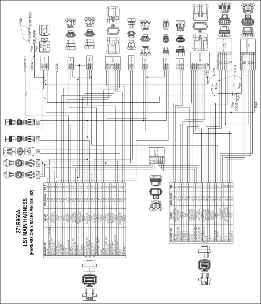
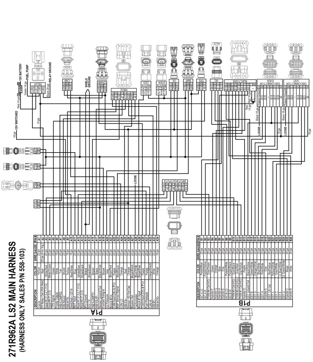
2 Main Harness The following quick guide overviews all connections on the Main Harness. The Main Harness supports all the primary engine sensors, fuel and ignition for 8 cylinder engines, the #1 wideband oxygen sensor, and the first four programmable input and output channels. There are two connectors for this harness designated as J1A (pin designations below that start with an A) and J1B (pin designations below that start with a B). The following descriptions indicate the name of the item and the name as labeled on the harness is shown in parenthesis. The pinout for the ECU is then shown. If the wires are terminated into the same connector on every type of main harness, the connector pinout is given as well. If the connector may vary by application, such as a TPS or IAC, the connector pinout is not given. To see the connector pinout for a specific application, locate the wiring diagram themselves contained in the WIRING APPENDIX, located in the software. Primary Sensors Crank Position Sensor (CRANK) Holley EFI systems work with 24X and 58X LS crank sensors. A30 Crank Input Signal A26 Sensor +5V Reference Out Camshaft Position Sensor (CAM) Holley EFI systems work with 1X and 4X LS cam sensors. A22 Cam Input Signal A26 Sensor +5V Reference Out Throttle Position Sensor (TPS) Holley EFI systems work with any 0-5V throttle position sensors. A5 TPS Signal A26 Sensor +5V Reference Out Manifold Air Pressure Sensor (MAP) Holley EFI systems work with 1, 2, 3, 4, or 5 Bar MAP sensors. Make sure to select the proper sensor used in the software. A23 MAP Sensor Signal A26 Sensor +5v Reference Out Coolant Temperature Sensor (CTS) Holley EFI systems work with any 2 wire thermistor style coolant temperature sensors. Make sure to select the proper sensor in the software. A19 Coolant Temp In Manifold Air Temperature Sensor (MAT) Holley EFI systems work with any 2 wire thermistor style manifold air temperature sensors. Make sure to select the proper sensor in the software. A11 Manifold Air Temp In Knock Sensor (Knock) Holley EFI systems work with either a one wire or two wire knock sensor. Application specific harnesses will have the correct knock sensor connections installed on the harness. A Universal harness comes with a 3 pin metripak connector. If a knock sensor is added, it should be connected into this connector A21 Knock Sensor #2 Input (Pin A) A29 Knock Sensor #1 Input (Pin B) (Pin C)
3 Wide Band Oxygen Sensor (WB02) Holley EFI systems can work with either a Bosch (PN ) or NTK (PN ) wide band oxygen sensor. These sensors must be purchased from Holley as they are calibrated specifically for use with Holley EFI systems. A34 WB1 HTR+ (Pin A) A9 WB1 HTR - (Pin B) A16 WB1 COMPR1 (Pin C) A7 WB1 CCOMPR2 (Pin D) A17 WB1 VS-/IP- (Pin E) A33 WB1 IP+ (Pin F) A25 WB1 VS+ (Pin G) A8 WB1 Shield (Pin H) Fuel Pressure (Fuel) A fuel pressure input is a standard feature on Holley EFI. A connector is installed that is plug-and-play with Holley 100 PSI pressure transducer PN A different 0-5V transducer can be used, but the calibration must be set up as a custom sensor in the software. If these are not connected to a pressure transducer, the Fuel and Oil Pressure will read LOW Err in the data monitor. This will not cause any issues. (Pin A) A26 Sensor +5V Reference Out (Pin B) A31 Fuel Pressure Signal (Pin C) Oil Pressure (Oil) An oil pressure input is a standard feature on Holley EFI. A connector is installed that is plug-and-play with Holley 100 PSI pressure transducer PN A different 0-5V transducer can be used, but the calibration must be set up as a custom sensor in the software. If these are not connected to a pressure transducer, the Fuel and Oil Pressure will read LOW Err in the data monitor. This will not cause any issues. (Pin A) A26 Sensor +5V Reference Out (Pin B) A20 Fuel Pressure Signal (Pin C) CANbus (CAN) All harnesses have a CANbus communications connector. This is used to communicate with CANbus devices, such as the Avenger Handheld tuning module or the 5.7 Touch Screen LCD. If these devices or any other CANbus device is not being used, there is no need to do anything with this connector. A24 CAN Lo (Pin B) A32 CAN Hi (Pin A) Primary Outputs Idle Air Control (IAC) The terminated IAC connector is for a 4 wire stepper type IAC. A 2 wire PWM (Pulse Width Modulated) IAC can be used, see section 9.2. The following shows the outputs for a stepper IAC. B1 IAC A Lo B2 IAC A Hi B8 IAC B Lo B9 IAC B Hi
4 Fuel Injector Outputs (Injectors) All terminated harnesses have a fuel injector connector. Various fuel injector harnesses plug into this connector. It is essential these harnesses are used so that injector firing sequence is maintained. Note that for engines with different firing orders, you do NOT change these pins. The engine s firing order is input in the software itself. Pin s A-H are routed to the cylinder number designation for the engine (i.e. A goes to cylinder #1, B goes to cylinder #2, etc). V8 harnesses offered by Holley are labeled for GM, Ford, and Chrysler engines. B19 Injector A (Pin A) B26 Injector B (Pin B) B25 Injector C (Pin C) B13 Injector D (Pin D) B7 Injector E (Pin E) B4 Injector F (Pin F) B5 Injector G (Pin G) B6 Injector H (Pin H) +12V Power (Pins J/K) DIS Connector Even Will connect to factory GM LS Coil harnesses. For Holley Smart Coils use PN Loose Chassis Ground (Pin A) B15 EST B/CYL 2 (Pin B) B16 EST D/CYL 4 (Pin C) Empty (Pin D) B14 EST Ground Out (Pin E) B17 EST F/CYL 6 (Pin F) B18 EST H/CYL 8 (Pin G) RELAY V Coil power (Pin H) DIS Connector Odd Will connect to factory GM LS Coil harnesses. For Holley Smart Coils use PN Loose Chassis Ground (Pin A) B24 EST G/CYL 7 (Pin B) B23 EST E/CYL 5 (Pin C) Empty (Pin D) B14 EST Ground Out (Pin E) B22 EST C/CYL 3 (Pin F) B21 EST A/CYL 1 (Pin G) RELAY V Coil power (Pin H) NOTE: On GM LSx engines, always install the black ignition ground wire in the harness to the engine block or cylinder head. NOTE: See section 8.0 of the Holley EFI User Manual for diagrams on wiring most ignition systems Loose Wires The following loose wires in the main wiring harness should be connected as follows on all systems: 12V Switched Color = Red/White Should be connected to a clean +12 volt power source. Power source should only be active when the ignition is on. Make sure source has power when engine is cranking as well. Not all sources apply power when the ignition switch is in cranking position. 12V Battery Color = Red Should be connected directly to the battery. There is a fuse holder attached that should contain a 20A rated fuse. This powers the fuel pump and fuel injectors. 12V Fuel Pump Color = Green - Used to directly power a fuel pump (+12 volt). Fully terminated harnesses utilize a relay to supply this power. 14 gauge wire is used. Due to this, it is not recommended for pumps that draw over Amps to use this wire. For high current pumps, use this wire to trigger a separate relay and use larger gauge wire to feed the pump - 10 gauge is recommended. Points Output Color = White Used to trigger a CD ignition box. See the ignition wiring section for detailed wiring. Ignition/DIS Chassis Ground Color = Black Connect to a ground point that has excellent connectivity with both the engine and the battery. Coil Color = Yellow Used for an RPM input signal when not controlling timing and NOT running a Capacitive Discharge (MSD) ignition system. See the ignition wiring section 8.0 for detailed wiring. WARNING! Connecting this wire to the coil of a CD ignition will damage the ECU.
5
6
7
8 ECU Pinout The following is a pinout of the J1A and J1B connectors: NOTE: ECU pinout is identical for the HP and Dominator. J1A Connector J1B Connector Pin Function Pin Function A1 Coil - Input B1 IAC A Lo A2 Fuel Pump Out (+12v) (10A Max) B2 IAC A Hi A3 Input #2 (F52THG) B3 Output #4 (G P-) A4 Input #4 (F5G) B4 Injector F Output A5 TPS Input B5 Injector G Output A6 Points Trigger Output B6 Injector H Output A7 WB1 COMPR2 B7 Injector E Output A8 WB1 Shield B8 IAC B Lo A9 WB HTR - B9 IAC B Hi A10 Switched +12v Input B10 Output #3 (G P-) A11 Manifold Air Temp Input B11 Output #2 (H P+) A12 Input #1 (F52THG) B12 Output #1 (H P+) A13 Input #3 (F5G) B13 Injector D Output A14 Cam/Crank Ground B14 EST Ground Output A15 Gauge Digital Output B15 EST 2 Output (Cylinder #2) A16 WB1 COMPR1 B16 EST 4 Output (Cylinder #4) A17 WB1 VS-/IP+ B17 EST 6 Output (Cylinder #6) A18 Sensor Ground B18 EST 8 Output (Cylinder #8) A19 Engine Coolant Temp Input B19 Injector A Output A20 Oil Pressure Input B20 EST 12V Output A21 Knock #2 Input B21 EST 1 Output (Cylinder #1) A22 Cam Sync Input / Ignition Bypass Output B22 EST 3 Output (Cylinder #3) A23 Map Sensor Input B23 EST 5 Output (Cylinder #5) A24 CAN Lo B24 EST 7 Output (Cylinder #7) A25 WB1 VS+ B25 Injector C Output A26 Sensor +5v B26 Injector B Output A27 NOT USED A28 EST/Spout Output A29 Knock #1 Input A30 Crank Speed Input A31 Fuel Pressure Input A32 CAN Hi A33 WB1 IP+ A34 WB HTR +
WIRING MANUAL & DIAGRAMS 199R10555
 WIRING MANUAL & DIAGRAMS 199R10555 HP EFI and Dominator EFI Systems Contents 1.0 Manual Overview... 2 1 1.1 Important Wiring Do s and Don ts... 3 2.0 ECU Installation, Connectors, and Pinout... 3 2.1 Pinout...
HP EFI UNIVERSAL RETROFIT KITS
 HP EFI UNIVERSAL RETROFIT KITS 550-500 (HP Universal Retrofit Kit for 4150 carb style intakes) 550-501 (HP Universal Retrofit Kit for 4500 carb style intakes) INSTALLATION INSTRUCTIONS 199R10510 NOTE:
HP EFI 4 BBL TBI SYSTEMS
 HP EFI 4 BBL TBI SYSTEMS 550-411 (900 CFM 75 lb/hr injectors) up to 525 HP 550-412 (900 CFM 85 lb/hr injectors) up to 600 HP NOTE: HP throttle body systems do not include fuel pump. TBI HARDWARE INSTALLATION
StealthRam Small Block Chevy Multi-Port EFI Systems Standard and Vortec Intake Versions
 StealthRam Small Block Chevy Multi-Port EFI Systems Standard and Vortec Intake Versions 550-820 (Early/Late Heads) 550-823 (Early/Late Heads) Polished 550-828 (Vortec Heads) Polished NOTE: Fuel pump and
Gen III HEMI Harness PN or
 Gen III HEMI Harness PN 558-106 or 558-107 This wiring harness interfaces a Holley EFI ECU to a Gen III HEMI engine. It is meant to be used in conjunction with an injector harness, a coil harness, and
MPFI FUEL INJECTION SYSTEM
 MPFI FUEL INJECTION SYSTEM PART NUMBERS 550-608 thru 550-615, 550-622 & 550-623 INSTALLATION & TUNING MANUAL 199R10762 NOTE: These instructions must be read and fully understood before beginning installation.
AVENGER EFI 4 BBL TBI SYSTEMS
 AVENGER EFI 4 BBL TBI SYSTEMS 550-400 (700 CFM 65 lb/hr injectors) up to 400 HP 550-401 (900 CFM 75 lb/hr injectors) up to 525 HP 550-402 (900 CFM 85 lb/hr injectors) up to 600 HP TBI HARDWARE INSTALLATION
Ford Coyote Non-VVT Main Harness PN
 Ford Coyote Non-VVT Main Harness PN 558-114 This wiring harness interfaces a Holley EFI ECU to a Ford Coyote engine that has had the cam VVT hardware locked out. It is meant to be used in conjunction with
AVENGER EFI 4 BBL MPFI SYSTEMS
 AVENGER EFI 4 BBL MPFI SYSTEMS SINGLE PLANE 4BBL SMALL BLOCK CHEVY MULTI-PORT EFI SYSTEMS 550-811 (Early/Late Models) 550-816 (Vortec Heads) SINGLE PLANE 4BBL BIG BLOCK CHEVY MULTI-PORT EFI SYSTEMS 550-831
Speed-Pro EFI Installation Manual
 Speed-Pro EFI Installation Manual Speed-Pro Electronics Installation Manual Page The wiring harness is labeled on each of the connectors to simplify installation. Your application may not require the use
Core Harness System Crank/Cam Adapter Harness FAST Dual Sync Distrubutor 35" STOP!
 Instruction Manual 30-3805-20 Core Harness System Crank/Cam Adapter Harness FAST Dual Sync Distrubutor 35" STOP! THIS PRODUCT HAS LEGAL RESTRICTIONS. READ THIS BEFORE INSTALLING/USING! THIS PRODUCT MAY
4 BBL THROTTLE BODY FUEL INJECTION SYSTEM
 4 BBL THROTTLE BODY FUEL INJECTION SYSTEM 550-405 950 CFM 200-600 HP Polished Aluminum 550-406 950 CFM 200-600 HP Hard Core Gray INSTALLATION MANUAL 199R10653 NOTE: These instructions must be read and
HP and Dominator Component Selection Guide. Use when building Dominator Systems or Custom HP Systems. Step 2 (notes) Choose Your Main Harness
 Choose Your Main Harness") HP and Dominator Component Selection Guide Use when building Dominator Systems or Custom HP Systems Step 1 (required) Choose your ECU & Main Power Harness Step 2 (notes) Choose Your Main Harness Step 3
HP and Dominator Component Selection Guide Use when building Dominator Systems or Custom HP Systems Step 1 (required) Choose your ECU & Main Power Harness Step 2 (notes) Choose Your Main Harness Step 3
Ford Coyote Main Harness and Harness Kit PN , , and
 Ford Coyote Main Harness and Harness Kit PN 558-110, 550-619, and 550-625 This wiring harness interfaces a Holley EFI ECU to a Ford Coyote engine that has either had the cam VVT hardware locked out or
StealthRam Small Block Chevy Multi-Port EFI Systems Standard and Vortec Intake Versions
 StealthRam Small Block Chevy Multi-Port EFI Systems Standard and Vortec Intake Versions 550-821 (Early/Late Heads) 550-822 (Early/Late Heads) Polished 550-826 (Vortec Heads) 550-827 (Vortec Heads) Polished
1. Index. LS Wiring Harness. 2. Presentation Warnings and Warranty Terms Overview Labels...7
 OWNER S MANUAL 1. Index 2. Presentation...4 3. Warnings and Warranty Terms...5 4. Overview...6 5. Labels...7 6. Diagrams...7 6.1 FT500/FT500 Aux - Inputs/outputs...7 6.2 Nano WB O2 #1...8 6.3 Nano WB
ELITE 1000/1500 Dodge SRT QUICK START GUIDE HT
 E N G I N E M A N A G E M E N T S Y S T E M S ELITE 1000/1500 Dodge SRT4 03-05 QUICK START GUIDE HT-140940 LIMITED WARRANTY Lockin Pty Ltd trading as Haltech warrants the HaltechTM Programmable Fuel Injection
DISTRIBUTORLESS IGNITION SYSTEM Installation and Adjustment Instructions
 DISTRIBUTORLESS IGNITION SYSTEM Installation and Adjustment Instructions 1.0 INTRODUCTION: Congratulations on your purchase of a Holley Distributorless Ignition System! Holley cannot and will not be responsible
E-STREET 2 EFI IGNITION CONTROL KIT Part #3674, 3675, 3676, 3679, 3680 INSTALLATION INSTRUCTIONS
 E-STREET 2 EFI IGNITION CONTROL KIT Part #3674, 3675, 3676, 3679, 3680 INSTALLATION INSTRUCTIONS PLEASE study these instructions carefully before beginning this installation. Most installations can be
Timing Input Adapter User Manual
 Timing Input Adapter User Manual 30-3805-05 2 AEM Infinity Harness Manuals Introduction Several universal wiring harness options are available for Infinity products. They range in complexity from simple
QUICK START GUIDE 199R10546
 QUICK START GUIDE 199R10546 1.0 Overview This contains detailed information on how to use Holley EFI software and perform tuning that is included within the software itself. Once you load the software,
MALLORY FIRESTORM CD MULTI COIL HARDWARE INSTALLATION - PN 69050S / 69050R
 FORM 69050S/R MALLORY FIRESTORM CD MULTI COIL HARDWARE INSTALLATION - PN 69050S / 69050R To ensure you are using the most current instruction sheet, please visit www.malloryfirestorm.com. CAUTION! The
2 Wire PW Idle Adapter User Manual
 2 Wire PW Idle Adapter User Manual 30-3805-08 2 AEM Infinity Harness Manuals Introduction Several universal wiring harness options are available for Infinity products. They range in complexity from simple
LSx Harness Installation. lsxeverything.com #BecauseYouShould
 LSx Harness Installation lsxeverything.com #BecauseYouShould Table of Contents Slide 1 Introduction Page Slide 2 Table of Contents Slide 3 Starting Instructions Slide 4 Power Connections Slide 5 Ground
MALLORY FIRESTORM CD MULTI COIL HARDWARE INSTALLATION - PN 69150C / 69150R
 FORM 69150C/R MALLORY FIRESTORM CD MULTI COIL HARDWARE INSTALLATION - PN 69150C / 69150R To ensure you are using the most current instruction sheet, please visit www.malloryfirestorm.com. CAUTION! The
Programmable 8 Channel Injector Driver Module
 Overview: Programmable 8 Channel Injector Driver Module 554-142 The 8 channel fuel injector driver module allows for an input signal from any ECU to be changed into a user selectable peak and hold current.
4 BBL THROTTLE BODY FUEL INJECTION MASTER KIT
 4 BBL THROTTLE BODY FUEL INJECTION MASTER KIT 550-405K 950 CFM Polished Aluminum Throttle Body + Complete Fuel System 550-406K 950 CFM Hard Core Gray Throttle Body + Complete Fuel System FUEL INJECTION
, & REFERENCE MANUAL
 550-510, 550-511 & 550-516 REFERENCE MANUAL Contents PARTS IDENTIFICATION... 2 MASTER KIT FUEL SYSTEM INSTALLATION... 4 GENERAL WIRING REFERENCE... 9 SYSTEM WIRING OVERVIEW... 12 IGNITION WIRING... 13
MegaSquirt III for LS Style Engines. Hardware Install. 1. Disconnect and remove the battery from the vehicle.
 MegaSquirt III for LS Style Engines MegaSquirt controllers are experimental devices intended for educational purposes. MegaSquirt controllers are not for sale or use on pollution controlled vehicles. Check
8 Injector 4150 Super Sniper EFI ( Shiny, Black, & Gold) 4 Injector 4150 Super Sniper EFI ( Shiny, Black, &
 4 Injector 4150 Super Sniper EFI ( Shiny, Black, &") 8 Injector 4150 Super Sniper EFI (550-512 Shiny, 550-513 Black, & 550-517 Gold) 4 Injector 4150 Super Sniper EFI (550-518 Shiny, 550-519 Black, & 550-520 Gold) 1 Holley Sniper EFI FUEL INJECTION INSTALLATION
8 Injector 4150 Super Sniper EFI (550-512 Shiny, 550-513 Black, & 550-517 Gold) 4 Injector 4150 Super Sniper EFI (550-518 Shiny, 550-519 Black, & 550-520 Gold) 1 Holley Sniper EFI FUEL INJECTION INSTALLATION
1CH Ignition Adapter Harness User Manual
 CH Ignition Adapter Harness User Manual 30-3805-02 2 AEM Infinity Harness Manuals Introduction Several universal wiring harness options are available for Infinity products. They range in complexity from
Installation Instructions for: EMS P/N and U Honda S2000
 Installation Instructions for: EMS P/N 30-1052 and 30-1052U 00-04 Honda S2000! WARNING: This installation is not for the tuning novice nor the PC illiterate! Use this system with EXTREME caution! The AEM
INSTALLATION INSTRUCTIONS. Revision 3.1.1
 INSTALLATION INSTRUCTIONS Revision 3.1.1 Table of Contents INTRODUCTION... 4 INSTALLATION OVERVIEW... 5 Included Parts... 6 DEVICE WIRING... 7 Required Parts... 7 Guidelines... 7 Wiring Diagram... 8 Compatible
Installation Instructions for: EMS P/N Ford Mustang 5.0L
 Installation Instructions for: EMS P/N 30-1401 1994-95 Ford Mustang 5.0L! WARNING: This installation is not for the tuning novice nor the PC illiterate! Use this system with EXTREME caution! The AEM EMS
1. Index. PRO600 Wiring Harness. 2. Presentation Warnings and Warranty Terms Overview PRO600 Harness...6
 OWNER S MANUAL 1. Index 2. Presentation...4 3. Warnings and Warranty Terms...5 4. Overview...6 4.1 PRO600 Harness...6 5. Versions and components...7 5.1 PRO600 components...7 6. Labels...8 7. Diagrams...9
PLATINUM Sport Haltech GM LS1 / LS6 Terminated Engine Harness (HT045650) QUICK START GUIDE
 QUICK START GUIDE") PLATINUM Sport 2000 Haltech GM LS1 / LS6 Terminated Engine Harness (HT045650) QUICK START GUIDE LIMITED WARRANTY Lockin Pty Ltd trading as Haltech warrants the Haltech TM Programmable Fuel Injection System
PLATINUM Sport 2000 Haltech GM LS1 / LS6 Terminated Engine Harness (HT045650) QUICK START GUIDE LIMITED WARRANTY Lockin Pty Ltd trading as Haltech warrants the Haltech TM Programmable Fuel Injection System
Installation Instructions for: EMS P/N Ford Mustang 5.0L
 Installation Instructions for: EMS P/N 30-1400 1986-93 Ford Mustang 5.0L! WARNING: This installation is not for the tuning novice nor the PC illiterate! Use this system with EXTREME caution! The AEM EMS
MegaSquirt III for Gen 3 HEMI. Hardware Install THE FOLLOWING SENSOR PART NUMBERS APPLY TO ALL HARNESSES FOR ENGINES 2004 TO CURRENT:
 MegaSquirt III for Gen 3 HEMI MegaSquirt controllers are experimental devices intended for educational purposes. MegaSquirt controllers are not for sale or use on pollution controlled vehicles. Check the
IT S ELECTRIC SWITCHING TO HOLLEY EFI YIELDS BETTER DRIVABILITY AND MORE POWER FOR A BOOSTED 68 FIREBIRD
 WORDS: Scott Parker PICTURES: By Redline Motorsports IT S ELECTRIC SWITCHING TO HOLLEY EFI YIELDS BETTER DRIVABILITY AND MORE POWER FOR A BOOSTED 68 FIREBIRD I t s been said many times, and often it has
Installation Instructions for: EMS P/N Dodge Viper V-10
 Installation Instructions for: EMS P/N 30-1500 1996-02 Dodge Viper V-10! WARNING: This installation is not for the tuning novice nor the PC illiterate! Use this system with EXTREME caution! The AEM EMS
Holley EFI 16 Injector Setup (8 Cylinder Engines) Setup of 8 Injectors in 8:2 Amp Peak and Hold Mode
 Setup of 8 Injectors in 8:2 Amp Peak and Hold Mode") Holley EFI 16 Injector Setup (8 Cylinder Engines) Setup of 8 Injectors in 8:2 Amp Peak and Hold Mode TABLE OF CONTENTS: 16 Injector Setup (4 Options)... 1 General Information... 2 16 Injector Option 1...
Holley EFI 16 Injector Setup (8 Cylinder Engines) Setup of 8 Injectors in 8:2 Amp Peak and Hold Mode TABLE OF CONTENTS: 16 Injector Setup (4 Options)... 1 General Information... 2 16 Injector Option 1...
Quadrajet Sniper EFI ( Shiny, Black, & Gold)
") Quadrajet Sniper EFI (550-867 Shiny, 550-868 Black, & 550-869 Gold) 1 Holley Sniper EFI FUEL INJECTION INSTALLATION MANUAL WARNING! Read this manual before using this product. This instruction manual must
Quadrajet Sniper EFI (550-867 Shiny, 550-868 Black, & 550-869 Gold) 1 Holley Sniper EFI FUEL INJECTION INSTALLATION MANUAL WARNING! Read this manual before using this product. This instruction manual must
GM EV6 Injector Adapter Harness User Manual
 GM EV6 Injector Adapter Harness User Manual 30-3805-0 THIS PRODUCT IS LEGAL IN CALIFORNIA FOR RACING VEHICLES ONLY AND SHOULD NEVER BE USED ON PUBLIC HIGHWAYS. Introduction Some harness user manuals contain
MPFI FUEL INJECTION SYSTEM
 MPFI FUEL INJECTION SYSTEM PART NUMBERS 550-903 thru 905, 550-916 thru 918 & 550-926 thru 931 HANDHELD TUNING AND REFERENCE MANUAL 199R11761 1 CONTENTS Tuning... 4 Basic... 4 Basic Fuel... 4 Closed Loop
Syvecs S6 GP. Syvecs Limited. Pinouts and Wiring Info. Ryan Griffiths
 1 Syvecs Limited Syvecs S6 GP Pinouts and Wiring Info Ryan Griffiths 24 10 2011 This document intended for use by a technical audience and describes a number of procedures that are potentially hazardous.
This product is legal in California for racing vehicles only and should never be used on public highways.
 Installation Instructions for: EMS P/N 30-1602 and 30-1602U 96-99 Nissan 180SX SR20DET 97-98 Nissan Silvia S14 SR20DET 93-98 Nissan Silvia S14 SR20DET (Europe) 99-02 Nissan Silvia S15 SR20DET! WARNING:
INSTALLATION INSTRUCTIONS. Revision 4.0.3
 INSTALLATION INSTRUCTIONS Revision 4.0.3 Table of Contents INTRODUCTION... 3 INSTALLATION OVERVIEW... 4 Included Parts... 5 DEVICE WIRING... 6 Required Parts... 6 Guidelines... 6 Wiring Diagram... 7 Engine
PLATINUM. Sport Haltech 13B Terminated Engine Harness QUICK START GUIDE
 PLATINUM Sport 1000 Haltech 13B Terminated Engine Harness QUICK START GUIDE HALTECH HEAD OFFICE: PH: +612 9729 0999 FAX: +612 9729 0900 EMAIL: sales@haltech.com HALTECH US OFFICE: EMAIL: usa@haltech.com
Adaptronic esel015 Select ECU for Nissan R32/R33/R34GTR Skyline and Z32 300ZX / Fairlady
 1 P a g e Adaptronic esel015 Select ECU for Nissan R32/R33/R34GTR Skyline and Z32 300ZX / Fairlady Applicable vehicles / engines: Nissan Skyline R32 (GTST and GTR) RB20DET and RB26DETT Nissan Skyline R33
MS3-Pro LSx Drop On Harness
 24x MS3-Pro LSx Drop On Harness For engines with 24X crank triggers Thank you for buying our drop on wiring harness! We have designed this harness to support anything from a stock motor swapped into a
4150 Sniper EFI ( Shiny, Black, & Gold)
") 4150 Sniper EFI (550-510 Shiny, 550-511 Black, & 550-516 Gold) 1 Holley Sniper EFI FUEL INJECTION INSTALLATION MANUAL WARNING! Read this manual before using this product. This instruction manual must be
4150 Sniper EFI (550-510 Shiny, 550-511 Black, & 550-516 Gold) 1 Holley Sniper EFI FUEL INJECTION INSTALLATION MANUAL WARNING! Read this manual before using this product. This instruction manual must be
4. Remove distributor hold-down. Lift the distributor upwards and remove.
 Holley Sniper EFI HyperSpark Distributors are designed to plug and play with Sniper EFI systems. This design includes a single Hall Effect sensor providing crankshaft speed to the ECU. The precision machined
Installation Instructions for: EMS P/N Toyota Supra
 Installation Instructions for: EMS P/N 30-1110 1987-1988 Toyota Supra! WARNING: This installation is not for the tuning novice nor the PC illiterate! Use this system with EXTREME caution! The AEM EMS System
Adaptronic esel020 Select ECU for Nissan S13 240SX (KA24DE) / RNN14 GTiR / SR20VE
 / RNN14 GTiR / SR20VE") 1 P a g e Adaptronic esel020 Select ECU for Nissan S13 240SX (KA24DE) / RNN14 GTiR / SR20VE Applicable vehicles / engines: Nissan S13 KA24DE 240SX US Market Nissan N14 SR20DET / SR20VE - Pulsar GTi-R /
1 P a g e Adaptronic esel020 Select ECU for Nissan S13 240SX (KA24DE) / RNN14 GTiR / SR20VE Applicable vehicles / engines: Nissan S13 KA24DE 240SX US Market Nissan N14 SR20DET / SR20VE - Pulsar GTi-R /
INFINITY APPLICATION GUIDE
 PLUG & PLAY APPLICATIONS INFINITY SERIES 7 INFINITY PLATFORM** Vehicle Adapter Harness Make Year Model Engine 708 710 712 Part # Adapter Harness BMW 2001 2006 E46 M3 S54 3.2L Inline 6 30 7109 30 7105 N/A
PLUG & PLAY. Quick Start Guide. GM LS 58X Drop On Harness. MS3Pro ULTIMATE
 Quick Start Guide PLUG & PLAY GM LS 58X Drop On Harness MS3Pro ULTIMATE For GM LS Engines with 58X Crank Triggers Thank you for your purchase and support for American made products! We have designed this
Instruction Manual. P/N Suzuki GSXR1300 Hayabusa 6 Speed Plug & Play Adapter Harness
 Instruction Manual P/N 30-3550 2002-2007 Suzuki GSXR1300 Hayabusa 6 Speed Plug & Play Adapter Harness OVERVIEW The 30-3550 AEM Infinity Adapter Kit was designed for the 2002 2007 Suzuki GSXR1300 Hayabusa.
HOWELL INSTALLATION MANUAL. Tuned Port Or LT-1 Fuel Injection Harness ( )
") HOWELL ENGINE DEVELOPMENTS, INC. FUEL INJECTION APPLICATIONS INSTALLATION MANUAL Tuned Port Or LT-1 Fuel Injection Harness (1985-1992) Howell Engine Developments, Inc. 6201 Industrial Way Marine City,
HOWELL ENGINE DEVELOPMENTS, INC. FUEL INJECTION APPLICATIONS INSTALLATION MANUAL Tuned Port Or LT-1 Fuel Injection Harness (1985-1992) Howell Engine Developments, Inc. 6201 Industrial Way Marine City,
FAST XIM. XIM Unit Installation
 1 INSTRUCTIONS XIM Thank you for choosing products; we are proud to be your manufacturer of choice. Please read this instruction sheet carefully before beginning installation, and also take a moment to
Installation Instructions for: EMS P/N Acura Integra Acura 2.3CL Honda Accord Honda Civic
 ! Installation Instructions for: EMS P/N 30-1010 00-01 Acura Integra 98-99 Acura 2.3CL 98-02 Honda Accord 99-00 Honda Civic WARNING: This installation is not for the tuning novice nor the PC illiterate!
Installation Instructions for: EMS P/N Toyota MR2 Turbo Toyota Celica All Trac
 Installation Instructions for: EMS P/N 30-1120 1991-1992 Toyota MR2 Turbo 1990-1992 Toyota Celica All Trac! WARNING: This installation is not for the tuning novice nor the PC illiterate! Use this system
HOWELL INSTALLATION MANUAL. Throttle Body Fuel Injection Harness
 HOWELL ENGINE DEVELOPMENTS, INC. FUEL INJECTION APPLICATIONS INSTALLATION MANUAL Throttle Body Fuel Injection Harness Howell Engine Developments, Inc. 6201 Industrial Way Marine City, MI 48039 Phone: 810-765-5100
Gallardo LP520 Kit. Thank you for choosing the Syvecs LP520 Gallardo kit. The kit comes with the following: 1 x Syvecs S12 Ecu
 Gallardo LP520 Kit Thank you for choosing the Syvecs LP520 Gallardo kit The kit comes with the following: 1 x Syvecs S12 Ecu 1 x Gallardo LP520 Wiring Loom 1 x 12way DTM Connector 1 x Syvecs GFA Module
GM Throttle Body Adapter Harness User Manual
 GM Throttle Body Adapter Harness User Manual 30-3809-01 THIS PRODUCT IS LEGAL IN CALIFORNIA FOR RACING VEHICLES ONLY AND SHOULD NEVER BE USED ON PUBLIC HIGHWAYS. AEM Performance Electronics AEM Performance
This is the layout of a typical harness form a TPI Camaro.
 TPI wiring harness, typical 1986-89: This is the layout of a typical harness form a 1986-88 TPI Camaro. (A) bulkhead conn. through firewall. (B) ecm conn. (C) jct. conn for fuel injectors and cooling fan.
GENERAL MOTORS SERVICE PARTS OPERATION 6200 Grand Pointe Drive, Grand Blanc, MI 48439
 LS IGNITION CONTROLLER 19355418 Ignition Control for Carbureted LS Series Engines (24x Crankshaft Index/1x Camshaft Index, 58x Crankshaft Index/4x Camshaft Index) Parts Included Quantity Ignition Controller
Installation Instructions for: EMS P/N Toyota Supra
 Installation Instructions for: EMS P/N 30-1130 1989-1992 Toyota Supra! WARNING: This installation is not for the tuning novice nor the PC illiterate! Use this system with EXTREME caution! The AEM EMS System
Quick Start Guide. This is only a quick start guide. A full wiring and installation manual is included in PCLink.
 Quick Start Guide This is only a quick start guide. A full wiring and installation manual is included in PCLink. Installer I/O Table Wire Description Installer Connection Typical Application +14V Bat Full
CPi. CoiL PACK IGNiTioN FOR AViATiON. For 4,6 and 8 cylinder 4 stroke applications. Please read the entire manual before beginning installation.
 1 CPi CoiL PACK IGNiTioN FOR AViATiON Coil pack (4 cylinder) Coil pack (6 cylinder) For 4,6 and 8 cylinder 4 stroke applications. Please read the entire manual before beginning installation. Software version
Installation Instructions for: EMS P/N Honda S2000
 Installation Instructions for: EMS P/N 30-6052 2000-2005 Honda S2000! WARNING: This installation is not for the tuning novice nor the PC illiterate! Use this system with EXTREME caution! The AEM EMS System
GM Stepper Idle Adapter User Manual
 GM Stepper Idle Adapter User Manual 30-3805-07 THIS PRODUCT IS LEGAL IN CALIFORNIA FOR RACING VEHICLES ONLY AND SHOULD NEVER BE USED ON PUBLIC HIGHWAYS. AEM Performance Electronics AEM Performance Electronics,
QUICKSTART MANUAL SNIPER EFI INSTALLATION INSTRUCTIONS
 550-510, 550-511, & 550-516 QUICKSTART MANUAL SNIPER EFI INSTALLATION INSTRUCTIONS Congratulations on your purchase of a new Sniper EFI Throttle Body System built by craftsmen to exacting standards in
2009 Yamaha Apex Snowmobile
 PARTS LIST 2009 Yamaha Apex Snowmobile Installation Instructions quantity description 1 power commander 1 USB cable 1 cd-rom 1 installation guide 2 power commander decals 2 dynojet decals 2 velcro strip
GM Injector Adapter Harness User Manual
 GM Injector dapter Harness User Manual 30 3805 00 2 EM Infinity Harness Manuals Introduction Several universal wiring harness options are available for Infinity products. They range in complexity from
TELORVEK III. WIRING INSTRUCTIONS FOR LT-40 LT-1 Fuel Injection System
 TELORVEK III WIRING INSTRUCTIONS FOR LT-40 LT-1 Fuel Injection System Page #1 Thank you for purchasing the absolute finest of wiring kits for the General Motors fuel injection. We have taken considerable
2011 Yamaha Apex Snowmobile
 PARTS LIST 2011 Yamaha Apex Snowmobile Installation Instructions quantity description 1 power commander 1 USB cable 1 cd-rom 1 installation guide 2 power commander decals 2 dynojet decals 2 velcro strip
Kubota Engine Training: WG1605, spark ignited
 Kubota Engine Training: WG1605, spark ignited WG1605 Engine Training: System Overviews Mechanical Components Electronic Components and Sensors Operation Service Tool Fuel System Overview: Fuel System Overview:
Installation Instructions for: EMS P/N Silvia S13 SR20DET Nissan 180SX SR20DET
 Installation Instructions for: EMS P/N 30-6601 1991-1993 Silvia S13 SR20DET 1991-1995 Nissan 180SX SR20DET! WARNING: This installation is not for the tuning novice nor the PC illiterate! Use this system
Installation Guide. Thank you for the purchase of our product. You have just unleashed infinite control, power and ability into your hands.
 Installation Guide Thank you for the purchase of our product. You have just unleashed infinite control, power and ability into your hands. This product is for race use only by experienced engine tuners.
Crank Trigger Hardware Installation
 Crank Trigger Hardware Installation Step 1 - Bring the engine up to TDC and remove the crank pulley bolt. Step 2 - Install trigger wheel making sure to line up the keyway. You may need to use the bolt
MaxxECU quickstart guide ( )
") Be a tuning mastermind. Like us. MaxxECU quickstart guide (2019-02-01) Online help! maxxecu.com/support Wiring diagrams Installation help Pinout Support maxxecu.com/support Legal disclaimer All performance
Be a tuning mastermind. Like us. MaxxECU quickstart guide (2019-02-01) Online help! maxxecu.com/support Wiring diagrams Installation help Pinout Support maxxecu.com/support Legal disclaimer All performance
Megasquirt EX, Installation Instructions document revision 1.4 (Includes also the version equipped with wasted-spark ignition)
") Megasquirt EX, Installation Instructions document revision 1.4 (Includes also the version equipped with wasted-spark ignition) General Megasquirt EX is a programmable engine control system, based on Megasquirt
Megasquirt EX, Installation Instructions document revision 1.4 (Includes also the version equipped with wasted-spark ignition) General Megasquirt EX is a programmable engine control system, based on Megasquirt
Installation Instructions for: EMS P/N Acura Integra Acura 2.3CL Honda Accord Honda Civic
 Installation Instructions for: EMS P/N 30-6050 00-01 Acura Integra 98-99 Acura 2.3CL 98-02 Honda Accord 99-00 Honda Civic Thank you for purchasing an AEM Engine Management System. The AEM Engine Management
PLEASE READ ALL DIRECTIONS BEFORE STARTING INSTALLATION
 PARTS LIST FUEL AND IGNITION 2014 Suzuki GW250 Installation Instructions 1 Power Commander 1 USB Cable 1 CD-ROM 1 Installation Guide 2 Power Commander Decals 2 Dynojet Decals 2 Velcro strips 1 Alcohol
WOLF3D. Installation Manual. Version 4.57 Engine Management System with WIDEBAND AFR. Revision Number 1.004
 WOLF3D Version 4.57 Engine Management System with WIDEBAND AFR Installation Manual Revision Number 1.004 Printed January 27, 2016 CONTENTS 1 Introduction... 5 2 ECU... 6 2.1 Mounting the ECU... 6 2.2 Diagnostic
service bulletin MCM 454 Magnum EFI, MIE 454 EFI Ski GM Gen V Engine Specifications No Magnum 454 EFI Model EFI Ski (Average Octane Rating)
") service bulletin TO: SERVICE MANAGER MECHANICS PARTS MANAGER No. 93-25 MCM 454 Magnum EFI, MIE 454 EFI Ski GM Gen V Engine Specifications NOTE: Generation V Engines Have the Fuel Pump Mounted on the Belt
service bulletin TO: SERVICE MANAGER MECHANICS PARTS MANAGER No. 93-25 MCM 454 Magnum EFI, MIE 454 EFI Ski GM Gen V Engine Specifications NOTE: Generation V Engines Have the Fuel Pump Mounted on the Belt
INSTALLATION INSTRUCTIONS for. FC 2000 Series
 INSTALLATION INSTRUCTIONS for Fire Control (FC) Ignition System FC 2000 Series Owners Manual Introduction...2 Specifications...2 Coil Compatibilities...2 Wire Functions...2 Connections...3-6 Connections
WARNING! USE ONLY IN RACE OR OTHER CLOSED COURSE APPLICATIONS AND NEVER ON PUBLIC ROADS
 2013-2014 Ducati Multistrada 1200 Z-Fi INSTALLATION INSTRUCTIONS P/N F185 WARNING! USE ONLY IN RACE OR OTHER CLOSED COURSE APPLICATIONS AND NEVER ON PUBLIC ROADS Z-Fi products do not meet California CARB
MSD-8 Plus Ignition PN 7805
 MSD-8 Plus Ignition PN 7805 Note: Solid Core spark plug wires cannot be used with an MSD Ignition. Parts Included: 1 - MSD-8 Plus Ignition 1 - Mag Pickup Extension Harness, PN 8860 4 - Vibration Mounts
Fig.11 Powertrain Control Module (PCM)
") 2003 Dodge or Ram Truck Caravan V6-3.3L VIN R Vehicle > Powertrain Management > Relays and Modules - Powertrain Management > Relays and Modules - Computers and Control Systems > Engine Control Module >
2003 Dodge or Ram Truck Caravan V6-3.3L VIN R Vehicle > Powertrain Management > Relays and Modules - Powertrain Management > Relays and Modules - Computers and Control Systems > Engine Control Module >
ECU Pinout Chart 2002 WRX Engine Control Module (ECM) I/O Signals. Wire Ignition SW Color ON Engine ON (Idling)
 I/O Signals. Wire Ignition SW Color ON Engine ON (Idling)") ECU Connector Diagram ECU Pinout Chart 2002 WRX Engine Control Module (ECM) I/O Signals Signal (V) Content Pin Wire Ignition SW Color ON Engine ON (Idling) Note (Engine OFF) Crankshaft Signal (+) B2 W
ECU Connector Diagram ECU Pinout Chart 2002 WRX Engine Control Module (ECM) I/O Signals Signal (V) Content Pin Wire Ignition SW Color ON Engine ON (Idling) Note (Engine OFF) Crankshaft Signal (+) B2 W
HYFIRE 6.6 SERIES OF ELECTRONIC IGNITION CONTROL
 FORM 1486M 03/05 INSTALLATION INSTRUCTIONS HYFIRE 6.6 SERIES OF ELECTRONIC IGNITION CONTROL HYFIRE 6.6 IGNITION SYSTEM PART NO. 686M FOR APPLICATIONS TRIGGERED BY POINTS, MALLORY ELECTRONIC IGNITION DISTRIBUTOR
MSD 6LS-2 Ignition Controller for Carbureted and EFI LS 2/LS 7 Engines PN 6012
 MSD 6LS-2 Ignition Controller for Carbureted and EFI LS 2/LS 7 Engines PN 6012 ONLINE PRODUCT REGISTRATION: Register your MSD product online. Registering your product will help if there is ever a warranty
TELORVEK TPI WIRING INSTRUCTIONS FOR TH-90 (95 CK TRUCK) 4.3,5.0,5.7,7.4 TBI Fuel Injection System W/4L60-E or 4L80-E Transmission
 4.3,5.0,5.7,7.4 TBI Fuel Injection System W/4L60-E or 4L80-E Transmission") Page #1 TELORVEK TPI WIRING INSTRUCTIONS FOR TH-90 (95 CK TRUCK) 4.3,5.0,5.7,7.4 TBI Fuel Injection System W/4L60-E or 4L80-E Transmission Thank you for purchasing the absolute finest of wiring kits for
Page #1 TELORVEK TPI WIRING INSTRUCTIONS FOR TH-90 (95 CK TRUCK) 4.3,5.0,5.7,7.4 TBI Fuel Injection System W/4L60-E or 4L80-E Transmission Thank you for purchasing the absolute finest of wiring kits for
PLEASE READ ALL DIRECTIONS BEFORE STARTING INSTALLATION
 PARTS LIST 2017 Victory 106 Models Installation Instructions 1 Power Commander 1 USB Cable 1 Installation Guide 2 Power Commander Decals 2 Dynojet Decals 2 Velcro strips 1 Alcohol swab 2 O2 Optimizers
Cylinder Head Replacement
 CYLINDER HEAD REPLACEMENT (EN... CYLINDER HEAD REPLACEMENT (ENGINE MECHANICAL - 1.6L) Document ID# 1430093 Cylinder Head Replacement Tools Required J 45059 Angle Meter KM-470-B Angular Torque Gauge J 42492-A
Fuel Metering System Component Description
 1999 Chevrolet/Geo Tahoe - 4WD Fuel Metering System Component Description Purpose The function of the fuel metering system is to deliver the correct amount of fuel to the engine under all operating conditions.
Data Unit Value Coolant temperature 0.436V (130 ) ~4.896V (-40 )
 ~4.896V (-40 )") 149000 153 1. ENGINE DATA LIST Data Unit Value Coolant temperature 0.436V (130 ) ~4.896V (40 ) Intake air temperature 40~130 (varies according to ambient air temperature or engine mode) Idle speed rpm
149000 153 1. ENGINE DATA LIST Data Unit Value Coolant temperature 0.436V (130 ) ~4.896V (40 ) Intake air temperature 40~130 (varies according to ambient air temperature or engine mode) Idle speed rpm
MSD-8 Plus Ignition PN 7805
 MSD-8 Plus Ignition PN 7805 ONLINE PRODUCT REGISTRATION: Register your MSD product online. Registering your product will help if there is ever a warranty issue with your product and helps the MSD R&D team
Installation Instructions for: EMS P/N Eclipse Turbo, Talon Tsi, Laser RS Galant VR4
 Installation Instructions for: EMS P/N 30-6300 1990-1994 Eclipse Turbo, Talon Tsi, Laser RS Galant VR4 Thank you for purchasing an AEM Engine Management System. The AEM Engine Management System (EMS) is