MPFI FUEL INJECTION SYSTEM
|
|
|
- Cecily Harvey
- 5 years ago
- Views:
Transcription


1 MPFI FUEL INJECTION SYSTEM PART NUMBERS thru 905, thru 918 & thru 931 HANDHELD TUNING AND REFERENCE MANUAL 199R
2 CONTENTS Tuning... 4 Basic... 4 Basic Fuel... 4 Closed Loop / Learn... 5 Basic Idle... 5 Spark... 5 Drive-By-Wire... 6 Transmission... 6 System... 9 Outputs... 9 Engine Setup... 9 Fuel Setup... 9 Terminator X Setup Ignition Setup Transmission Advanced Advanced Fuel Closed Loop Adv. Learn Adv. Idle Monitor Monitors Multi-Gauge Custom Dash # Channels Scaling Advanced Features Nitrous Stage 1 Activation Stage 1 Tuning Boost Launch Safety Setup Boost vs. Speed Boost vs. RPM Boost vs. Gear Boost vs. Time
3 Launch Step Launch Retard Advanced ICF D Tables D Tables Logging File ECU Overview Page Page Local Setup Touch Calibrate Local Info Local Options Screen Brightness ECU HW/FW Global Configs Laptop Support Downloading & loading calibrations from the Terminator X to an SD card: Inputs & Outputs APPENDIX 1.0 ECU PINOUT APPENDIX 2.0 ENGINE CONNECTOR AND INJECTOR INFORMATION EV MULTEC Supported Fuel Injectors APPENDIX 3.0 THROTTLE BODIES AND PEDALS PIN CONNECTOR (LATE) PIN CONNECTOR (EARLY TRUCK) THROTTLE PEDAL APPENDIX 4.0 DIAGNOSTIC LEDS APPENDIX 5.0 HARNESS DRAWINGS
4 TUNING BASIC The TERMINATOR X handheld allows the user to perform tuning changes to help optimize mileage, drivability, and performance. The tuning is split up into Basic Tuning and Advanced Tuning sections. BASIC FUEL Allows changes to the Target Air/Fuel ratio at idle, cruise, and wide open throttle. The following are typical values and tuning notes. TARGET AFR TARGET AFR AT IDLE Typically between 13.5 and Engines with larger cams may need a richer setting for smoothest idle. TARGET AFR AT CRUISE Typically between 13.5 and Engines with larger cams may need a richer setting. TARGET AFR AT WOT Typically between 12.5 and 13.2 on Naturally Aspirated engines. Running richer may reduce power. Running leaner may reduce power or cause potential engine damage. TARGET AFR BOOST OFFSET Use the slider bar to input the desired target AFR Offset per 7 lbs of boost. ACCELERATION ENRICHMENT ACCELERATION ENRICHMENT Changes the accelerator pump function of the fuel injection. Raising the number increases the amount of fuel added when the pedal is pushed. Lowering the number decreases the amou nt of fuel added when the pedal is pushed. It is highly recommended NOT to change this until the ECU is allowed to perform self -tuning. FUEL PRIME FUEL PRIME ENABLE Fuel prime is an option that is enabled by default in all of the base calibrations. The fu el prime function injects a small shot of fuel into the intake runners when the ignition is turned on, allowing the engine to start much quicker. The amount of fuel is based on the engine temperature and how long it was since the engine previously ran. This amount of fuel can be increased or decreased by changing the Percent value. If the engine seems flooded reduce this value, if the engine seems to want more fuel, increase it. Experiment for best results. Typically this value will range from % with a maximum of 200% typically used NOTE: THE ECU ONLY INJECTS FUEL ONCE AT KEY-ON, AND WILL NOT DO IT AGAIN UNTIL THE ENGINE HAS RUN. THIS FUEL PRIME OCCURS ½ OF A SECOND AFTER KEY- ON. IF YOU QUICKLY TURN THE IGNITION KEY WITHOUT WAITING FOR ½ A SECOND, THE PRIME WILL NOT OCCUR AND IT MAY TAKE LONGER FOR THE ENGINE TO START. FUEL PRIME PERCENT If the engine seems flooded reduce this value, if the engine seems to want more fuel, increase it. Experiment for best results. Typically this value will range from % with a maximum of 200%. 4
5 CLOSED LOOP / LEARN CLOSED LOOP CLOSED LOOP ENABLE/DISABLE This menu enables or disables closed loop operation. There is typically no reason to turn off closed loop operation unless you suspect an oxygen sensor problem and want to disable the sensor. NOTE: SELF-TUNING REQUIRES CLOSED LOOP OPERATION TO FUNCTION. MIN CTS ENABLED Enable or disable the minimum coolant temp for closed loop operation. COOLANT TEMP Once enabled, use this to set the minimum coolant temp for closed loop operation. TRANSFER TABLE This will transfer data from the Learn Map to the Base Fuel map. FUEL LEARN FUEL LEARN ENABLE/DISABLE The LEARN Enable / Disable menu turns the Self Tuning On and Off. If enabled, self -tuning is performed. Learning should be enabled when an engine is first run with the Terminator X and the tuning process is occurring. After the vehicle is driven under various operating conditions, and is running well, it is advised to limit the amount of learning that can occur to 10% or less in the Advanced Learn menu. BASIC IDLE Selecting BASIC IDLE allows you to change the Target Hot Engine Idle Speed. This should be adjusted to your desired idle RPM. Values between rpm are typical. Larger camshafts or aftermarket torque converters may require a slightly higher value to maintain proper idle quality while in gear. HOT ENGINE IDLE SPEED This will adjust the target HOT (above 160 F) idle speed. SPARK IGNITION TIMING AT IDLE 8-22 degrees is typically used at idle. The larger the camshaft, the more timing is usually used. IGNITION TIMING AT CRUISE degrees is typically used when cruising for optimal fuel economy. IGNITION TIMING AT WOT Varies by engine, but typically values range between 25 and 34 for Naturally Aspirated engines. CRANKING IGNITION TIMING This is the actual timing during cranking. It is set to 15 degrees at any RPM below 400 by default. 5
6 DRIVE-BY-WIRE The Pedal vs. Throttle Position table is the primary method of tuning a Drive -By-Wire throttle body system. The Pedal Position represents the position of the accelerator pedal. The user can adjust the Throttle Position to change based on the pedal position. This allows the user to increase or decrease throttle body position (engine airflow) to tailor the responsiveness of the engine. It can allow for an overly-large throttle body to have good driving manners or a small throttle body to be very responsive. On new installations, Idle Tuning must be performed on the Pedal vs. Throttle table. It is a similar adjustment to opening or closing the throttle plates with the idle set screw on a standard cable driven throttle body. TAKE CARE WHEN TUNING THE PEDAL VS. THROTTLE TABLE. WHEN YOU INCREASE THE PEDAL POSITION VALUE AT A CERTAIN TPS VOLTAGE, THE THROTTLE WILL GO TO THAT POSITION AT THAT TPS VOLTAGE SETTING. IT IS EXTREMELY IMPORTANT THAT YOU PAY CLOSE ATTENTION AND ARE NOT DISTRACTED WHEN MAKING CHANGES TO THE PEDAL VS. THROTTLE CABLE CURVE WITH THE TOUCH SCREEN. ANY CHANGES TO THIS CURVE SHOULD BE MADE WITH THE SYSTEM OFFLINE AND NOT WHILE THE ENGINE IS RUNNING AND ONLINE. THE CURVE OF THIS GRAPH SHOULD ALWAYS BE LOW AT LOW (IDLE) PEDAL POSITION AND INCREASE TO FULLY OPEN AT HIGH PEDAL POSITIONS. IF YOU DO NOT FULLY UNDERSTAND THIS GRAPH, DO NOT ATTEMPT TO MAKE ANY CHANGES TO THE SYSTEM. LOCATE A KNOWLEDGEABLE INSTALLER/TUNER OR CONTACT HOLLEY PERFORMANCE TECHNICAL SERVICE FOR ASSISTANCE. THE FIRST DATA POINT IN THIS TABLE IS LIMITED TO A VALUE OF 20%, THE SECOND CELL 30%, AND THE FOURTH CELL 40%. ALL OTHER CELLS ALLOW FOR THE THROTTLE BODY TO BE COMMANDED TO 100% THROTTLE BODY OPENING. PEDAL VS THROTTLE Once the engine is warm and idling in neutral, refer to the IAC Position value in the data monitor. You want this value to read between 5-15%. If it reads higher, turn the engine off and increase the first cell value (Pedal Position = 0%) in 1% increments until the IAC is in the 5-15% range. If the IAC position is at 0%, follow the same procedure but lower the first cell value until the IAC reads 5-15%. WARNING: ENGINE MUST BE TURNED OFF BEFORE MODIFYING THE PEDAL VS THROTTLE TABLE! TRANSMISSION SHIFTS CAUTION MUST BE USED WHEN MODIFYING TRANSMISSION PARAMETERS. LOWERING LINE PRESSURES TOO MUCH CAN CAUSE RAPID WEAR AND DAMAGE TO THE TRANSMISSION. THE BASE CALIBRATIONS PROVIDED SHOULD PROVIDE A SAFE BASE CALIBRATION. IF THE TRANSMISSION HAS VERY SOFT SHIFTS OR SEEMS TO SLIP, IMMEDIATELY STOP TO DIAGNOSE WHETHER THE PROBLEM IS DUE TO TUNING OR MECHANICAL ISSUES. Each Up-shift and Down-shift can be completely configured by selecting Shifts from the transmission menu. All Upshift points must occur at a higher speed than downshift. The touchscreen will give a warning and not allow this to occur if requested. Although it can be programmed with the handheld, the ECU won t allow a downshift to occur if it will over -rev the past the MAXIMUM RPM in the SYSTEM>TRANSMISSION>TRANS SETUP area. 6
7 SHIFT UP 1 ST -2 ND Table used to modify 1-2 upshift based on throttle position (or MAP for boosted applications) and speed. SHIFT DOWN 2 ND -1 ST Table used to modify 1-2 downshift based on throttle position (or MAP for boosted applications) and speed. SHIFT UP 2 ND -3 RD Table used to modify 2-3 upshift based on throttle position (or MAP for boosted appli cations) and speed. SHIFT DOWN 3 RD -2 ND Table used to modify 3-2 downshift based on throttle position (or MAP for boosted applications) and speed. SHIFT UP 3 RD -4 TH Table used to modify 3-4 upshift based on throttle position (or MAP for boosted applications) and speed. SHIFT DOWN 4 TH -3 RD Table used to modify 4-3 downshift based on throttle position (or MAP for boosted applications) and speed. WOT SHIFTS Use this menu to choose the RPM at which the transmission will upshift at WOT. Each gear change may be adjusted independent of the others. 1-2 WOT UPSHIFT This is the RPM at which the 1-2 upshift will occur. 2-3 WOT UPSHIFT This is the RPM at which the 1-2 upshift will occur. 3-4 WOT UPSHIFT This is the RPM at which the 1-2 upshift will occur. TORQUE CONVERTER CLUTCH (TCC) PARAMS Contains parameters that tune TCC activation and deactivation. THE TCC WILL NOT APPLY UNTIL THE ENGINE IS ABOVE 122 F, AS WELL AS A TRANSMISSION FLUID TEMPERATURE ABOVE 46 F. MINIMUM RPM TO ENABLE TCC This is the minimum RPM at which the Torque Converter Clutch will enable. This value can be adjusted so that engines with large camshafts do not hesitate surge if the TCC is applied at too low of an engine speed. RPM TO DISABLE TCC Used to unlock the TCC once it is locked. The Lock and Unlock values should not be too close together, or they will continuously lock and unlock. Applications with high stall torque converters will typically need RPM or more between these values. 7
8 MAXIMUM TPS TCC Throttle position value when the TCC will unlock. Most lockup torque converters do not have a clutch designed to lock up when higher power is being applied. It is best to unlock the converter under moderate to hard acceleration. Typically TPS values should be between 25-50%. TCC DISABLE This will disable TCC functionality in all conditions. TCC (UN)LOCK These parameters work in addition to the TCC Parameters by offering additional tuning based on vehicle speed. This keeps the TCC from locking up during around-town driving if it is not desired. The Lock values should always be higher than the Unlock values. Adjustments to these can be done by using the graph. TCC LOCK This is a table to adjust when the TCC locks based upon throttle position and vehicle speed. TCC UNLOCK This is a table to adjust when the TCC unlocks based upon throttle position and vehicle speed. LINE PRESSURE Tune the line pressure vs. TPS or MAP for each gear. A lower duty cycle (moving towards 0%) increases line pressure with 0% providing maximum line pressure applied. Values above 40-50% typically result in a line pressure too low for any throttle position, which may result in transmission damage. Naturally aspirated and nitrous calibrations created through the wizard use TPS for line pressure vs. load scaling, whereas turbo or supercharged cals use map sensor for line pressure vs load scaling. LINE PRESSURE 1 ST GEAR Editable line pressure curve for 1 st gear LINE PRESSURE 2 ND GEAR Editable line pressure curve for 2 nd gear LINE PRESSURE 3 RD GEAR Editable line pressure curve for 3 rd gear LINE PRESSURE 4 TH GEAR Editable line pressure curve for 4 th gear NON-ELECTRONIC TRANS Used for GM TH700R4 transmissions that have a lockup torque converter. Note that this should be used to drive a relay that is used in conjunction with a brake pedal switch disable. The brake pedal switch is not part of the EFI logic for this transmission type. ENABLE TCC OUTPUT Creates an output that can be used to trigger the relay used for the torque converter clutch solenoid activation. TCC OUTPUT Allows the user to select an available output pin. NOTE: THIS OUTPUT IS USED TO TRIGGER A RELAY. THE ECU OUTPUT TRIGGER WIRE SHOULD NEVER BE DIRECTLY CONNECTED TO THE TCC SOLENOID. See THE INPUT & OUTPUS SECTION for more information on the input and outputs. 8
9 MIN TPS FOR LOCKUP TPS positions below this parameter will unlock the torque converter. MIN RPM FOR LOCKUP Converter will not lock unless engine speed is above this value. MIN CTS FOR LOCUP Converter will not lock unless Engine Coolant Temperature is above this value. WOT UNLOCK TPS If enabled, converter will unlock above this TPS. SYSTEM OUTPUTS FAN #1 ON TEMPERATURE The OUTPUT screen allows for the Fan #1 and Fan #2 ON and OFF temperatures to be adjusted. The ON temp needs to always be a higher value than the OFF temp. Use a difference of at least 5 degrees so they aren t cycling excessively. In Sniper Kits, these are ground outputs that should be wired to trigger a fan relay. NEVER wire them directly to the fans! Preset to 195 F FAN #1 OFF TEMPERATURE Preset to 180 F. FAN #2 ON TEMPERATURE Preset to 205 F. FAN #2 OFF TEMPERATURE Preset to 190 F. AC SHUTDOWN MAX TPS The AC Disable value is a TPS value above which a ground output is sent out to deactivate the air conditioning compressor at wide open throttle Preset to 50%. ENGINE SETUP ENGINE DISPLACEMENT This value should reflect your actual engine size. The base fuel table calculates proper fuel flow based upon this value. FUEL SETUP FUEL PUMP PRIME This is how long the fuel pump will run for when the ignition if first turned on to pressurize the system and there is no rpm signal. 9
10 CLEAR FLOOD TPS Above this value, no fuel will be injected when the engine is cranking/starting. Typically set to 65% or higher. RATED FLOW PER INJECTOR Fuel Injector flow in lb/hr RATED INJECTOR FUEL PRESSURE Pressure at which injectors flow was rated at (psi) NOTE: DO NOT CONFUSE THIS VALUE WITH ACTUAL SYSTEM FUEL PRESSURE! ACTUAL SYSTEM FUEL PRESSURE This is the actual fuel system pressure of the vehicle. All Terminator X LS base calibrations are configured for 60 psi. NOTE: INCORRECT ENTRY WILL CAUSE THE FUELING TO BE INACCURATE. TERMINATOR X SETUP INJECTION TYPE Displays the current injection strategy SYSTEM TYPE Displays fuel injector information IGNITION SETUP IGNITION SETUP #1 IGNITION TYPE Displays the ignition type information IGNITION SETUP #2 FIRING ORDER Displays the engines selected firing order MAIN REV LIMITER TYPE View and edit the main rev limiter type. There are five types to choose from: Fuel Only performs a hard cut of fuel flow only when the main over -rev HIGH RPM is hit. Hard cut means that fuel flow is stopped to all cylinders until the main over -rev LOW RPM setting is met. Spark Only performs a hard cut of ignition only when the main over-rev HIGH RPM is hit. Hard cut means that ignition is stopped to all cylinders until the main over -rev LOW RPM setting is met. Fuel and Spark performs a hard cut of ignition AND fuel flow when the main over -rev high RPM is hit. Soft begins a soft cut of ignition when the main over-rev LOW RPM is hit. Soft cut means that ignition will be removed from individual cylinders as needed to limit RPM. If the HIGH RPM limit is reached, a hard cut will be implemented. Spark, high only This type has a single high side value. It is recommended to use this for a 2 -step rev limiter and as a high side rev limiter. 10
11 IT IS USUALLY BEST TO HAVE A NARROW RANGE (20-50 RPM) BETWEEN THE LOW AND HIGH RPM SETTINGS TO REDUCE STRESS ON THE ENGINE. MAIN REV LIMITER HIGH RPM See rev limiter types above MAIN REV LIMITER LOW RPM See Rev limiter types above STATIC TIMING GET SET NOT AVAILABLE FOR REV LIMITER TYPE SPARK, HIGH ONLY This gets the commanded static timing value that has been set previously, if user nav igated away from static timing check screen and the ignition has not been cycled. This sets the commanded timing to the chosen value. CLEAR This clears the static timing value. CLOSE This closes the Static Timing menu. TRANSMISSION TRANS SETUP TRANSMISSION TYPE Displays the calibration s transmission type MAXIMUM RPM If this RPM is exceeded when in manual shift mode, the transmission will upshift automatically. If a manual downshift is performed, and this RPM will be exceeded, the downshift will not be allowed. SPEED CALC TIRE DIAMETER Measure and enter the real tire diameter (inches). REAR GEAR RATIO Enter the rear axle gear ratio. 11
12 ADVANCED ADVANCED FUEL STARTUP ENRICHMENT CRANKING FUEL This dictates how much fuel is injected when the engine is c ranking and is dependent on coolant temperature. Changing this value offsets the entire curve at all temperatures. Adjustment values are in pounds of fuel per hour (PPH) and should initially be adjusted in increments of 2-4 PPH. AFTER START HOLDOFF The amount of time after engine starts to when the after start fuel is deployed. AFTER START ENRICHMENT The afterstart parameter is fuel that is added for a short time immediately after an engine starts. This value varies depending on engine temperature. Changing this value offsets the entire curve at all temperatures. Adjustments are made as a percentage of the base map from 75% to 200%, 100% would mean no additional fuel is being added, 110% would mean that an additional 10% of fuel is being added to the ba se fuel map, and 85% would mean that 15% of fuel is being taken away from the base map. All selections will decay back to 100% over a predetermined amount of time. AFTER START DECAY RATE The amount of time it takes for the After Start Enrichment to decay to zero. ACCELERATION ENRICHMENT AE VS. TPS RATE OF CHANGE Ads additional, momentary fuel based on the rate of change of the TPS. Same function as an accelerator pump on a carburetor. AE VS. MAP RATE OF CHANGE This parameter provides another way of adding fuel when the accelerator is depressed. It adds fuel depending on how fast the MAP sensor reading changes (detects a change in engine load). There is typically no need to adjust this parameter except possibly under some extreme conditions of vehicles that are heavy or underpowered. Adjustment values are in pounds of fuel per hour ( PPH) and should initially be adjusted in increments of 5-10 PPH. AE TPS VS COOLANT TEMP This curve adjusts the acceleration enrichment as a function of coolant temperature and T PS rate of change. This should not need to be adjusted. MAP AE TIME VS COOLANT The length of time it takes for the AE vs. MAP fuel to decay from peak value to 0. MAP AE VS COOLANT Modifies the AE vs. MAP Rate of Change Graph based on engine coolant temper ature. 12
13 TEMPERATURE ENRICHMENT COOLANT TEMP ENRICHMENT Coolant enrichment is similar to the choke on a carburetor. Adjustments are made as a percentage of the base map from 100% to 150%. 100% would mean no additional fuel is being added by the Coolant Enrichment, 110% would mean that an additional 10% of fuel is being added to the base fuel map which will decay back to 100% in relation to actual engine coolant temperature. A/F RATIO OFFSET A positive value LEANS the target A/F ratio and a negative valu e RICHENS the target A/F ratio. AIR TEMP ENRICHMENT The Air Temperature Enrichment % table is used to add additional fuel based on air temperature. As air gets colder it typically becomes denser, requiring more fuel. This table is beneficial to minimize closed loop correction values. IDLE FUEL IDLE FUEL TRIM This modifies the VE fuel table values in the idle area of the fuel map. It is only available when the Minimum RPM to enter closed loop feature has been enabled and configured. NOTE: BASE CALIBRATIONS MADE THROUGH THE WIZARD THAT USE CAMSHAFT TYPE 3 HAVE CLOSED LOOP DISABLED BELOW 2500 RPM BY DEFAULT. CLOSED LOOP CLOSED LOOP #1 CLOSED LOOP ENABLE / DISABLE This menu enables or disables closed loop operation. There is typically no reason to turn o ff closed loop operation unless you suspect an oxygen sensor problem and want to disable the sensor. NOTE: SELF-TUNING REQUIRES CLOSED LOOP OPERATION TO FUNCTION. CLOSED LOOP + LIMIT The maximum percentage the ECU is allowed to add to the base fuel calibration in order to maintain the commanded target air fuel ratio. This is set to 50% by default and under most circumstances should not need to be changed. CLOSED LOOP LIMIT The maximum percentage the ECU is allowed to remove from the base fuel calibration in order to maintain the commanded target air fuel ratio. This is set to 50% by default and under most circumstances should not need to be changed. CLOSED LOOP SPEED This is the speed (gain) at which closed loop operation occurs. This can be set to five levels, 1, 2, 3, 4, or 5. 3 is the base setting and should be good for most applications. 4 or 5 is typically not used as the closed loop speed may be too excessive for certain applications. If the oxygen sensor is installed far back in the exhau st (more than 1 foot back from the collector in long tube headers), a value of 1 or 2 may be needed. 13
14 CLOSED LOOP #2 ENABLE RPM TO ENTER CL Enable or Disable minimum RPM required to enter closed loop operation. RPM TO ENTER CL Below the Engine Speed value entered, the engine will not operate closed loop it will operate open loop. ENABLE MIN CTS TO ENTER CL Enable or Disable minimum coolant temperature required to enter closed loop operation. CTS TO ENTER CL Below the Engine Coolant Temperature value entered, the engine will not operate closed loop it will operate open loop. ENABLE TPS TO ENTER CL Enable or Disable minimum throttle position required to enter closed loop operation. TPS TO ENTER CL Below the Throttle Position value entered, the engine will not operate closed loop it will operate open loop. ADV. LEARN LEARN + LIMIT This value is set to 100% by default, and should remain there until ample driving time and tuning has occurred. The LEARN COMPENSATION LIMIT is a parameter that ECU is allowed to work within when making changes to the fuel map based upon CLOSED LOOP operation. Unlike the CLOSED LOOP LIMIT which is a set parameter for commanded changes to actual fuel flow based upon the O2 sensor reading, LEARN COMPENSATION LIMITS are the percentage of change that is allowed to actually be saved as a modifier to the fuel map. LEARN LIMIT This value is set to 100% by default, and should remain there until ample driving time and tuning has occurred. The LEARN COMPENSATION LIMIT is a parameter that ECU is allowed to work within when making changes to the fuel map based upon CLOSED LOOP operation. Unlike the CLOSED LOOP LIMIT which is a set parameter for commanded changes to actual fuel flow based upon the O2 sensor reading, LEARN COMPENSATION LIMITS are the percentage of change that is allowed to actually be saved as a modifier to the fuel map. ENABLE RPM TO ENTER LEARN Enable or Disable minimum RPM required to enter learn. RPM TO ENTER LEARN Below the Engine Speed value entered, the ECU will not populate the learn table. ENABLE TPS TO ENTER LEARN Enable or Disable minimum throttle position required to enter learn. TPS TO ENTER LEARN Below the Throttle Position value entered, the ECU will not populate the learn table. 14
15 ADV. IDLE Cable Throttle Bodies The Idle Air Control (IAC) motor is a stepper motor located in the throttle body that controls the idle speed of the engine by metering air. It also operates during engine cranking and when the engine returns back to idle. The IAC moves from a position of 0% (fully closed, no air added) to 100% (fully open, maximum air flow). Drive-By-Wire Throttle Bodies Unlike a cable throttle body with separate IAC stepper motor, a DBW throttle body modulates the actual blade position to maintain commanded idle settings. IAC RAMPDOWN IAC HOLD POSITION This is the position the IAC motor will hold or freeze at when the TPS moves above idle (when TPS becomes greater than 0%). If it is too high, the engine RPM will hang and not return to idle. IAC RAMP DECAY This is the time (in seconds) it takes for the IAC to return to the target idle range of movement. IAC RAMP START (RPM ABOVE IDLE) This value is the RPM added to the target idle speed that the IAC will automatically start to ramp back down to idle. If this is too low, the engine RPM will hang and not return to idle. IAC KICK The IAC Kick provides a temporary increase in IAC position to keep engine the RPM from dropping. Typically, this is used in conjunction with an A/C system to keep the engine speed from di pping as the compressor cycles on and off. IAC CONTROL IAC CONTROL This menu is used to select the type of IAC motor application that is being used. This selection drives the background parameters that control the IAC motor. These parameters have been f ine tuned for each of these applications, eliminating the need for the user to perform further modifications. IAC STARTUP IAC PARKED POSITION (CRANKING) This is the position the IAC motor will be at during cranking and immediately after the engine starts. If it is too high, the engine will be at too high of an RPM once it starts too low and poor starting will result. Note that this is a temperature based table. The percentage value changed in the handheld offsets this entire curve. IAC STARTUP HOLD TIME This is the amount of time that the IAC will remain at the IAC Parked Position. Lower this if the engine 'hangs' at a higher RPM for too long after startup. IAC STARTUP DECAY TIME This is the amount of time for the IAC to decay from the IAC Parked Pos ition back to its Target Idle position. It is a linear decay. 15
16 IDLE SPARK IDLE SPARK ENABLE / DISABLE Idle spark is a feature active only when the ECU is controlling timing. When enabled, the ECU modifies commanded timing at idle to help maintain the target idle speed. P TERM NOTE: THIS FEATURE SHOULD BE DISABLED WHEN CHECKING BASE TIMING WITH A TIMING LIGHT AND NOT USING THE STATIC TIMING OPTION. Raising or lowering the P Term will change the speed at which the timing is allowed to change. Experim ent to see what the engine likes best. D TERM The D Term is used to help minimize overshoot. If you are unsure, just make the D term the same value as the P term to start. IDLE SPEED IDLE SPEED CURVE Unlike the Idle speed slider bar found in the Basic Tuning menu, this allows for full customization of target idle speed at all coolant temperatures MONITOR The Terminator X handheld display has a variety of pre-configured gauge screens. Three fully customizable screens are also included. Most channels allow for user-programmable caution and warning limits to provide visual indicators of parameters that are deemed to be out of range. MONITORS IDLE Engine RPM / TPS / IAC Position / Air/Fuel Ratio / Ignition Timing LEARN Fuel Learn Status / Current Learn / Closed Loop Compensation / Target Air/Fuel Ratio / Air/Fuel Ratio CLOSED LOOP Closed Loop Status / Closed Loop Compensation / Target Air/Fuel Ratio / Air/Fuel Ratio / Fuel Learn Status SENSORS MAP / TPS / MAT / CTS / Battery FUEL Engine RPM / Air/Fuel Ratio / Injection Pulse Width / Closed Loop Compensation / Fuel Duty Cycle INITIAL STARTUP Engine RPM / TPS / MAP / CTS / IAC position / Battery 16
17 MULTI-GAUGE SENSORS VITALS MAP / CTS / TPS / AFR / RPM / Battery / Ignition Timing / MAT / IAC Position / Injector Duty Cycle Fan #1 / Fan #2 / AC Shutdown / CTS / RPM / IAC Position / AFR / Battery / Closed Loop Status / Learn Status AIR/FUEL RATIO DASH #1 DASH #2 DASH #3 AFR / Target AFR / Coolant Enrichment / Closed Loop Compensation / RPM / Current Learn / Closed Loop Status / Learn Status / Injector Pulse Width / Fuel Flow This layout is transmission focused. Gear / RPM / Line Pressure / TCC Duty Cycle / TCC Lockup Status / Line Temp / Input Shaft Speed / TPS / Speed / Fuel Economy This layout is drive-by-wire focused. TPS / Pedal Position / Throttle Body Position / TB TPS #1 Voltage / Pedal TPS #1 Voltage / TB TPS #2 Voltage / Pedal TPS #2 Voltage / Brake Pedal Status / RPM / MAP Fan #1 / Fan #2 / AC Shutdown / CTS / IAC Position / AFR / Battery / Fuel Pressure / RPM / Oil Pressure CUSTOM DASH #1-3 Up to three (3) Custom gauge layouts can be created on the 3.5 Touch Screen. Follow these steps to configure: Step 1: Choose Dash Setup from the Multi-Gauge screen. Step 2: Choose the Dash number to be configured. Step 3: Choose the desired layout. Step 4: Select channels and choose gauge display types. CHANNELS SCALING Each channel displayed by the 3.5 Touch Screen can be configured to have caution and warning indicators. To do this, choose Channel Scaling from the MONITOR menu. Cautions will display as Yellow and Warnings will display as RED when using the Multi-Gauge screens. 17
18 ADVANCED FEATURES NITROUS STAGE 1 ACTIVATION NITROUS DISABLE If using Terminator X for Nitrous Control, this will Enable or Di sable the Stage. MIN RPM Minimum RPM required for Nitrous activation MAX RPM Maximum RPM allowed for Nitrous activation. Any RPM above this will turn off the stage. ACTIVATION DELAY This will delay the activation by the amount selected. The delay starts from the time the stage is triggered. A value of zero means the nitrous will turn on as soon as all activation conditions are met. STAGE DURATION This will set the duration of the nitrous stage, allowing a stage to be turned off at a precise time for brac ket racing, or for another layer of safety. This parameter is enabled by default. STAGE 1 TUNING FIXED TIMING VALUE If you are using Terminator X for timing control, this is the actual timing value the engine will operate with when the Nitrous is activated. PROGRESSIVE CONTROL Enable/Disable progressive timing retard curve. This parameter requires Terminator X laptop software to configure. TIMING RETARD 1x16 editable timing curve only available when not using a fixed timing value. This parameter requi res Terminator X laptop software to configure. TARGET AFR Closed Loop compensation will override the target AFR table and use this value as its new target only when the nitrous is on. BOOST LAUNCH LAUNCH TARGET Allows for a specific boost level to be maintained while this input is active, as well as creates a starting point for time based boost control (when launch input is de-activated). 18
19 SAFETY SETUP INSTANTANEOUS BOOST PRESSURE SAFETY Boost pressure above which ignition will be instantly cut TIME DELAY BOOST PRESSURE SAFETY Boost pressure above which ignition will be cut (with time delay) TIME DELAY Amount of time actual boost must be above time delay Boost Pressure to activate ignition cut BOOST VS. SPEED BOOST CURVE The units in this table are dome pressure, not boost pressure in the manifold. BOOST VS. RPM The units in these tables are dome pressure, not boost pressure in the manifold. GEAR 1 Boost vs. RPM curve for 1 st Gear GEAR 2 Boost vs. RPM curve for 2 nd Gear GEAR 3 Boost vs. RPM curve for 3 rd Gear GEAR 4 Boost vs. RPM curve for 4 th Gear BOOST VS. GEAR The units in these tables are dome pressure, not boost pressure in the manifold. GEAR 1 Boost vs RPM curve for 1 st Gear GEAR 2 Boost vs. RPM curve for 2 nd Gear GEAR 3 Boost vs. RPM curve for 3 rd Gear GEAR 4 Boost vs. RPM curve for 4 th Gear 19
20 BOOST VS. TIME BOOST CURVE This operating mode only has one curve. The units in the table are dome pressure, not b oost pressure in the manifold. LAUNCH 2-STEP REV LIMITER #1 ENABLE Enable or Disable Rev Limiter #1. REV LIMITER #1 INPUT Allows the user to select an available ECU input pin. See THE INPUT & OUTPUTS SECTION for more information on the input and outputs. REV LIMITER #1 TYPE View and edit rev limiter #1 type. There are five types to choose from: Fuel Only performs a hard cut of fuel flow only when the main over -rev HIGH RPM is hit. Hard cut means that fuel flow is stopped to all cylinders until the main over -rev LOW RPM setting is met. Spark Only performs a hard cut of ignition only when the main over-rev HIGH RPM is hit. Hard cut means that ignition is stopped to all cylinders until the main over -rev LOW RPM setting is met. Fuel and Spark performs a hard cut of ignition AND fuel flow when the main over-rev high RPM is hit. Soft begins a soft cut of ignition when the main over-rev LOW RPM is hit. Soft cut means that ignition will be removed from individual cylinders as needed to limit RPM. If the HIGH RPM limit is reached, a hard cut will be implemented. Spark, high only this type has a single high side value. It is recommended to use this for a 2 -step rev limiter and as a high side rev limiter. IT IS USUALLY BEST TO HAVE A NARROW RANGE (20-50 RPM) BETWEEN THE LOW AND HIGH RPM SETTINGS TO REDUCE STRESS ON THE ENGINE. REV LIMITER #1 ON RPM See Rev limiter types above. REV LIMITER #1 OFF RPM See Rev limiter types above. NOT AVAILABLE FOR REV LIMITER TYPE SPARK, HIGH ONLY 20
21 LAUNCH RETARD SETUP LAUNCH RETARD ENABLE TYPE Enable or Disable Launch Retard. Select the launch retard table units (Time or RPM). LAUNCH RETARD ACTIVATION Select whether the launch retard activates with an input, or at the release of an input (i.e. transbrake button). LAUNCH RETARD INPUT TUNING Allows the user to select an available ECU input pin. See THE INPUT & OUTPUTS SECTION for more information on the input and outputs. LAUNCH RETARD The table values are in degrees of retard, so a value of 5 would equate to a 5 degree retard in total timing. MIN RPM If RPM was selected as the table unit type, this is the first RPM point in the retard table. MAX RPM If RPM was selected as the table unit type, this is the last RPM point in the retard table. MIN TIME If time was selected as the table unit type, this is the first time point in the retard table. MAX TIME If time was selected as the table unit type, this is the last time point in the retard table. THE LAUNCH RETARD OPERATES OFF A 1X16 TABLE. THE BREAK-POINTS OF THE TABLE ARE FILLED IN A LINEAR FASHION BETWEEN THE MIN AND MAX (TIME OR RPM) INPUT VALUES. FINE TUNING OF THESE POINTS CAN BE DONE BY SELECTING TABLE ICON IN THE GRAPH EDITOR. ADVANCED ICF The configurations in the advanced tables must be setup using Terminator X Software. Once those are configured, a limited number of parameters may be adjusted in the handheld. Please read the Terminator X Software instructions to learn about and properly setup Advanced Tables. 21
22 1D TABLES TABLE #1 ENABLE Enables or disables the advanced table TABLE TYPE Displays the table type TIME DELAY ENABLE Enables or disables the table s activation time delay TIME DELAY TO START Edits the activation time delay EDIT CURVE Allows editing of the 1x16 table TABLE #2 See table #1 above TABLE #3 See table #1 above TABLE #4 See table #1 above 2D TABLES TABLE #1 ENABLE Enables or disables the advanced table TABLE TYPE Displays the table type TIME DELAY ENABLE Enables or disables the table s activation time delay TIME DELAY TO START Edits the activation time delay EDIT TABLE Allows editing of the 16x16 table TABLE #2 See table #1 above 22
23 TABLE #3 See table #1 above TABLE #4 See table #1 above LOGGING Terminator X MPFI systems come standard with powerful data logging capabilities. Logging can be stopped and started via the 3.5 Handheld, and the data logs will save automatically to the SD card. Choosing Files in the DATA LOGGING menu will display all logs contained on the SD card Automatic log triggering can be configured by choosing the setup icon. Data logs are timestamped and named using the following format: TermX_YYMMDD-hhmmss-XX.dlz Terminator X data logs can be viewed through the free Terminator X PC software. FILE ECU OVERVIEW PAGE 1 CURRENT GLOBAL FOLDER/FILE Displays the name of the current ECU calibration TRANSMISSION TYPE Displays the Calibration s configured transmission type IGNITION INPUT TYPE Displays the current Ignition Type WIDE BAND O2 SENSOR TYPE Displays the current O2 sensor type INJECTION TYPE Displays the current injection strategy SYSTEM TYPE Displays injector information 23
24 PAGE 2 ECU FIRMWARE VERSION Displays ECU firmware version ECU TIME Displays the ECU time. This time can be synced with actual time using Terminator X Software. TPS AUTOSET Indicates whether a TPS autoset has been performed LOCAL SETUP TOUCH CALIBRATE The touch screen can be recalibrated by following the on -screen instructions. LOCAL INFO Displays detailed handheld touchscreen firmware information LOCAL OPTIONS RESTORE SCREENS ON STARTUP SELECTING THIS OPTION WILL RESTORE THE HANDHELD TO THE LAST SCREEN IT WAS ON BEFORE IT WAS POWERED OFF. DO NOT SHOW ADVANCED FEATURES WARNING THIS WILL DISABLE THE WARNING THAT IS SHOWN WHENEVER THE ADVANCED FEATURES ICON IS SELECTED. SHOW TEMPERATURES IN C THIS WILL CONVERT TEMPERATURES SHOWN ON THE HANDHELD TO CELSIUS. THIS HAS NO EFFECT ON ECU FIRMWARE OR SOFTWARE TUNING IT IS A HANDHELD DISPLAY CONVERSION ONLY. RESTORE CHANNEL DEFAULTS THIS WILL RESTORE ANY USER CUSTOMIZED CHANNEL WARNING INDICATORS TO THE FACTORY DEFAULT VALUES. SCREEN BRIGHTNESS SCREEN BRIGHTNESS CAN BE MANUALLY ADJUSTED HERE. 0% IS THE LOWEST BRIGHTNESS SETTING, AND 100% IS THE BRIGHTEST. 24

25 ECU HW/FW This screen displays more detailed Terminator X ECU information, and is also where you go to upgrade ECU firmware. Watch this instructional video on how to update firmware GLOBAL CONFIGS List view of all saved Sniper calibrations on the SD card. This is where you can save, rename, and upload saved ECU calibrations (i.e. pump gas tune, race gas tune). 25
26 LAPTOP SUPPORT Your Terminator X system supports advanced tuning and data log review through use of the free sof tware, which can be downloaded here. Live tuning requires a CAN to USB cable. To view instructional videos on how to use Terminator X software visit the Holley YouTube channel Calibrations and data logs can also loaded to Terminator X software by using the handheld s SD card. DOWNLOADING & LOADING CALIBRATIONS FROM THE TERMINATOR X TO AN SD CARD: Downloading Calibration from ECU 1. Press File icon from the Main Menu Loading Calibration into Terminator X ECU 1. Press File icon from the Main Menu 2. Press the Global Configs Icon 2. Press the Global Configs Icon 3. Press Download From ECU 3. Highlight the Configuration you would like to load into the Terminator X (making it highlight in Blue). Press OK, if you would like to name it with a unique name, user can press Save GCF as, type the name for the calibration, and press save. 4. SD card now has the Global Configuration that is in the ECU unit, this can be opened up with the Terminator X software on a PC. 4. Press Upload to ECU and follow the Onscreen Prompts: a. Press okay when it asks, Upload GCF to ECU b. Turn the ignition off for at least 4 seconds when it asks you to. If you press OK, the upload of the calibration will not take place until the ignition is cycled. 5. New Configuration has been uploaded to the Terminator X ECU. 26
27 INPUTS & OUTPUTS The Terminator X ECU contains 4 configurable inputs and 4 configurable outputs: Base calibrations are pre-configured with 3 outputs and one input to be used for the following features: Electric Fan #1 output Electric Fan #2 output Air Conditioning Shutdown at Wide Open Throttle IAC Kick Input Additional features such as a launch retard or 2-step rev limiting can be configured through the handheld without the use of software. The following chart lists the connector and wire color information f or all of the inputs and outputs to aid in wiring and setup: Name ECU PIN Harness Connector Wire Color Function Type Input 1 A12 A White/Blue IAC Kick Ground Input 2 A3 B White/Red Unassigned Ground Input 3 A13 C White/Black Unassigned Ground Input 4 A4 D White/Green Unassigned Ground Output 1 B12 E Grey/Yellow Electric Fan 1 Ground Output 2 B11 F Grey/Red Electric Fan 2 Ground Output 3 B10 G Grey/Black AC Shutdown Ground Output 4 B3 H Grey/Green Unassigned Ground Further customization of the inputs and outputs, including changing their signal type can be performed via Terminator X software. 27
 (10A Max) B2 IAC A Hi A3 Input #2 (F,5,2,T,H,G) B3 PWM #4 Output (HG) A4 Input #4 (F,G,5)")
28 APPENDIX 1.0 ECU PINOUT The following shows pins that are used on TERMINATOR X systems. Pins that are not populated on TERMINATOR systems are denoted with an asterisk (*). J1A Connector J1B Connector Pin Function Pin Function A1 Coil Input B1 IAC A Lo A2 Fuel Pump Relay Out (+12v) (10A Max) B2 IAC A Hi A3 Input #2 (F,5,2,T,H,G) B3 PWM #4 Output (HG) A4 Input #4 (F,G,5) B4 Injector F (Cylinder 6) A5 TPS Input B5 Injector G (Cylinder 7) A6 Points Output B6 Injector H (Cylinder 8) A7 WB1 COMPR2 B7 Injector E (Cylinder 5) A8 WB1 Shield B8 IAC B Lo A9 WB HTR - B9 IAC B Hi A10 Switched +12v Input B10 PWM #3 Output (HG) A11 Manifold Air Temp Input B11 PWM #2 Output (HG) A12 Input #1 (F,5,2,T,H,G) B12 PWM #1 Output (HG) A13 Input #3 (F,G,5) B13 Injector D (Cylinder 4) A14 Cam/Crank Ground B14 Ground A15 Gauge Output B15 EST B (Cylinder 2) A16 WB1 COMPR1 B16 EST D (Cylinder 4) A17 WB1 VS-/IP+ B17 EST F (Cylinder 6) A18 Sensor Ground B18 EST H (Cylinder 8) A19 Engine Coolant Temp Input B19 Injector A (Cylinder 1) A20 Oil Pressure Input B20 EST 12V Output A21 Knock Sensor #2 Input B21 EST A (Cylinder 1) A22 Cam Input / Bypass Out B22 EST C (Cylinder 3) A23 Map Sensor Input B23 EST E (Cylinder 5) A24 CAN Lo B24 EST G (Cylinder 7) A25 WB1 VS+ B25 Injector C (Cylinder 3) A26 Sensor +5v B26 Injector B (Cylinder 2) A27 Bypass Out A28 EST/Spout Output A29 Knock Sensor #1 Input A30 Crank Speed Input A31 Fuel Pressure Input A32 CAN Hi A33 WB1 IP+ A34 WB HTR + 28


29 APPENDIX 2.0 ENGINE CONNECTOR AND INJECTOR INFORMATION THERE ARE THREE VARIATIONS OF LS INJECTOR CONNECTORS: EV1 INJECTOR HARNESS PART NUMBER


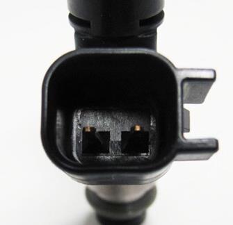
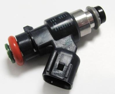
30 EV6 INJECTOR HARNESS PART NUMBER


31 MULTEC2 INJECTOR HARNESS PART NUMBER
32 SUPPORTED FUEL INJECTORS TERMINATOR X ECUS ONLY SUPPORT HIGH IMPEDANCE INJECTORS. THE USE OF LOW IMPEDANCE INJECTORS WILL DAMAGE THE ECU AND VOID THE WARRANTY. The list below outlines injectors that are preconfigured selectable through the wizard. If your injectors are not on this list, Terminator X software will be required to configu re before starting your engine. GM Holley Sniper Other 19LB Holley Sniper 42 lb/hr ( S) 24LB Holley LB Holley LB Holley LB Holley LB Holley LS GM Flex Fuel GM GM GM GM GM GM GM GM GM GM GM GM LB Siemens Deka IV FIC 525H FIC 650H FIC 775H FIC 850H FIC 1000H FIC 1100H FIC 1650H FIC 2150H 32
 DRIVE BY WIRE HARNESS PART NUMBER 558-406 12570790 o 2005-2008 Corvette, CTS-V and GTO o VIN Codes:")

 DRIVE BY WIRE HARNESS PART NUMBER 558-429 12570800 o 2002-2007 Truck o VIN Codes: B, N, P, T, U, V, Z o Engine Codes: L33, L59, LM4, LM7, LQ4 (truck), LQ9, LR4")
33 APPENDIX 3.0 THROTTLE BODIES AND PEDALS There are two styles of DBW throttle body connectors. The following part numbers are supported by Holley Terminator MPFI kits: 6 PIN CONNECTOR (LATE) DRIVE BY WIRE HARNESS PART NUMBER o Corvette, CTS-V and GTO o VIN Codes: E, U, W, Y o Engine Codes: L76, LQ4 (car), LS2, LS3, LS o Truck o VIN Codes: 0, 3, 4, 5, 8, C, H, J, K, L, M, Y o Engine Codes: L76, L92, LC9, LFA, LH6, LMF, LMG, LS2, LY2, LY5, LY o Corvette, Camaro, G8 o VIN Codes: E, J, W, Y o Engine Codes: L76, L99, LS3, LS o Truck o VIN Codes: 0, 2, 3, 4, 5, 7, 8, A, B, C, F, G, H, J, K, L, M, P, Y o Engine Codes: L20, L76, L92, L94, L96, L9H, LC8, LC9, LFA, LH6, LH8, LH9, LMF, LMG, LS2, LY2, LY5, LY6, LZ o 2001 thru 2005 Corvette & CTS-V o VIN Codes: G,S o Engine Codes: LS1, LS6 8 PIN CONNECTOR (EARLY TRUCK) DRIVE BY WIRE HARNESS PART NUMBER o Truck o VIN Codes: B, N, P, T, U, V, Z o Engine Codes: L33, L59, LM4, LM7, LQ4 (truck), LQ9, LR4 THROTTLE PEDAL Holley recommends GM P/N which is a passenger car pedal with a 6 pin connector. 33
34 APPENDIX 4.0 DIAGNOSTIC LEDS LED# Function Color Definition 1 Heartbeat Green/Flash ECU is powered 2 Engine running Green Engine is running Yellow Engine is not running 3 Wideband status Blue too hot, too cold, slow warmup, uncalibrated Green sensor is active and functioning properly Red sensor is open or needs to be replaced Yellow sensor is heating Off sensor is disabled 4 TPS calibrated Green Calibrated Red If DBW = Pedal & TB Calibration Error If non DBW - Calibration Error Cyan DBW Pedal Calibration Error Purple DBW TB Calibration Error 5 Off/undefined Future 6 Crank Green When below Crank to Run RPM, tooth detected Blue When below Crank to Run RPM, gap detected Red Crank error detected -If engine continues to run, will stay Red until ECU is powered off -If engine shuts off due to severe signal loss, will stay Red until RPM re-sync OR key cycle Off When above Crank to Run RPM and ECU is properly syncd 7 Cam Green When below Crank to Run RPM, tooth detected Blue When below Crank to Run RPM, gap detected Red Cam error detected -If engine continues to run, will stay Red until ECU is powered off -If engine shuts off due to severe signal loss, will stay Red until RPM re-sync OR key cycle Off When above Crank to Run RPM and ECU is properly syncd 8 Off/undefined Future 34
35 APPENDIX 5.0 HARNESS DRAWINGS LS1/6 ENGINE MAIN HARNESS 35
36 LS2/3/7+ ENGINE MAIN HARNESS 36
37 L60/80E TRANSMISSION HARNESS 37
38 DRIVE BY WIRE HARNESS (LATE) 38
39 DRIVE BY WIRE HARNESS (EARLY TRUCK) 199R11761 Date:
QUICK START GUIDE 199R10546
 QUICK START GUIDE 199R10546 1.0 Overview This contains detailed information on how to use Holley EFI software and perform tuning that is included within the software itself. Once you load the software,
EFI HARNESS KIT , & Kit Contents: Power Harness : All Kits
 EFI HARNESS KIT 558-500, 558-501 & 558-502 Kit Contents: Main Harness 558-102: Kits 558-500 558-103: Kits 558-501 & 502 Power Harness 558-308: All Kits Injector Harness 558-200: Kits 558-500 & 502 558-201:
WIRING MANUAL & DIAGRAMS 199R10555
 WIRING MANUAL & DIAGRAMS 199R10555 HP EFI and Dominator EFI Systems Contents 1.0 Manual Overview... 2 1 1.1 Important Wiring Do s and Don ts... 3 2.0 ECU Installation, Connectors, and Pinout... 3 2.1 Pinout...
MPFI FUEL INJECTION SYSTEM
 MPFI FUEL INJECTION SYSTEM PART NUMBERS 550-608 thru 550-615, 550-622 & 550-623 INSTALLATION & TUNING MANUAL 199R10762 NOTE: These instructions must be read and fully understood before beginning installation.
Lingenfelter NCC-002 Nitrous Control Center Quick Setup Guide
 Introduction: Lingenfelter NCC-002 Nitrous Control Center Quick Setup Guide The NCC-002 is capable of controlling two stages of progressive nitrous and fuel. If the NCC-002 is configured only for nitrous,
GENERAL MOTORS SERVICE PARTS OPERATION 6200 Grand Pointe Drive, Grand Blanc, MI 48439
 LS IGNITION CONTROLLER 19355418 Ignition Control for Carbureted LS Series Engines (24x Crankshaft Index/1x Camshaft Index, 58x Crankshaft Index/4x Camshaft Index) Parts Included Quantity Ignition Controller
GENERAL ANDROID DEVICE RECOMMENDATIONS
 GENERAL ANDROID DEVICE RECOMMENDATIONS The Edelbrock EFI E-Tuner app is compatible with most Android based Smartphones and tablets operating on Android 5.0 and later. However, due to slight variations
Active Speed Management Time based traction control based on engine speed and/or driveshaft speed.
 Contents V5 Feature Overview... 1 Custom Injector Setup... 2 Custom Injector Setup - System ICF... 2 Injector Set #1/#2/#3... 3 Driver Setup... 4 Custom Injector Setup - Fuel ICF... 5 Wiring Holley Injector
Subaru BRZ Toyota GT86 Scion FR-S
 RaceROM Features for Subaru BRZ Toyota GT86 Scion FR-S v1.8 Index Warning... 3 Introduction... 4 Feature list... 4 Supported Vehicle Models... 4 Availability... 4 Overview... 5 Map Switching**... 5 Speed
Controller Ground (dual black 12awg) should be connected to chassis ground as close as possible to the battery.
 should be connected to chassis ground as close as possible to the battery.") 1. Overview The Maximizer 4 progressive nitrous controller operates one or two separate stages of nitrous based on either time, RPM, MPH, throttle percentage or boost pressure. Whether your engine is naturally
1. Overview The Maximizer 4 progressive nitrous controller operates one or two separate stages of nitrous based on either time, RPM, MPH, throttle percentage or boost pressure. Whether your engine is naturally
Setup Tabs. Basic Setup: Advanced Setup:
 Setup Tabs Basic Setup: Password This option sets a password that MUST be entered to re-enter the system. Note: ProEFI can NOT get you into the calibration if you lose this password. You will have to reflash
Holley EFI V4 Software Overview
 Holley EFI V4 Software Overview File Changes The calibration file in V3 and earlier versions was called a Global Folder. The Global Folder was actually a Windows Folder which contained multiple files called
ProMax Progressive Controller Installation and Operation Instructions
 ProMax Progressive Controller Installation and Operation Instructions These instructions will guide you through the setup, installation, and use of the Nitrous Outlet Promax Progressive Controller. If
Holley EFI 16 Injector Setup (8 Cylinder Engines) Setup of 8 Injectors in 8:2 Amp Peak and Hold Mode
 Setup of 8 Injectors in 8:2 Amp Peak and Hold Mode") Holley EFI 16 Injector Setup (8 Cylinder Engines) Setup of 8 Injectors in 8:2 Amp Peak and Hold Mode TABLE OF CONTENTS: 16 Injector Setup (4 Options)... 1 General Information... 2 16 Injector Option 1...
Holley EFI 16 Injector Setup (8 Cylinder Engines) Setup of 8 Injectors in 8:2 Amp Peak and Hold Mode TABLE OF CONTENTS: 16 Injector Setup (4 Options)... 1 General Information... 2 16 Injector Option 1...
Direct Link Basic Tuning Guide (Delphi)
") Direct Link Basic Tuning Guide (Delphi) This Guide is intended to answer basic Direct Link tuning questions and to act as a Quick Start Guide. It is not intended to be the Gospel on the tuning process
Direct Link Basic Tuning Guide (Delphi) This Guide is intended to answer basic Direct Link tuning questions and to act as a Quick Start Guide. It is not intended to be the Gospel on the tuning process
QUICK START GUIDE. (407) /
 /") QUICK START GUIDE (407) 774-2447 / www.sctflash.com SECTION 1: PARTS + CHECKLIST X4 DEVICE MICRO USB CABLE HDMI/OBD II CABLE TOOLS NEEDED: Fuse Puller Voltage Tester Battery Charger Pliers SECTION 2: PRE-INSTALL
QUICK START GUIDE (407) 774-2447 / www.sctflash.com SECTION 1: PARTS + CHECKLIST X4 DEVICE MICRO USB CABLE HDMI/OBD II CABLE TOOLS NEEDED: Fuse Puller Voltage Tester Battery Charger Pliers SECTION 2: PRE-INSTALL
Handheld Controller Feature Definitions
 Basic Settings: These values and options allow Engine CID = Total Engine cubic inches Cam Mild-Wild 1-4 = This is the way to select a specific volumetric efficiency table that is specially tailored to
QUICKSTART MANUAL SNIPER EFI INSTALLATION INSTRUCTIONS
 550-510, 550-511, & 550-516 QUICKSTART MANUAL SNIPER EFI INSTALLATION INSTRUCTIONS Congratulations on your purchase of a new Sniper EFI Throttle Body System built by craftsmen to exacting standards in
Installation Instructions for: EMS P/N Ford Mustang 5.0L
 Installation Instructions for: EMS P/N 30-1400 1986-93 Ford Mustang 5.0L! WARNING: This installation is not for the tuning novice nor the PC illiterate! Use this system with EXTREME caution! The AEM EMS
4. Remove distributor hold-down. Lift the distributor upwards and remove.
 Holley Sniper EFI HyperSpark Distributors are designed to plug and play with Sniper EFI systems. This design includes a single Hall Effect sensor providing crankshaft speed to the ECU. The precision machined
HP EFI UNIVERSAL RETROFIT KITS
 HP EFI UNIVERSAL RETROFIT KITS 550-500 (HP Universal Retrofit Kit for 4150 carb style intakes) 550-501 (HP Universal Retrofit Kit for 4500 carb style intakes) INSTALLATION INSTRUCTIONS 199R10510 NOTE:
Installation Instructions for: EMS P/N Ford Mustang 5.0L
 Installation Instructions for: EMS P/N 30-1401 1994-95 Ford Mustang 5.0L! WARNING: This installation is not for the tuning novice nor the PC illiterate! Use this system with EXTREME caution! The AEM EMS
Allows 2 relays to be activated. based on RPM and throttle. This guide will give you a general overview to the use of the HUB
 Options Pressure input Map Switch Output Gear/Speed Input Allows the map to be trimmed Allows the user to change Allows 2 relays to be activated Allows the map to be trimmed based on pressure/boost input
Innovative Racing Electronics
 FOR IMMEDIATE RELEASE Contact: Dan Rudd Phone: 407.330.9727 FAX: 407.322.8632 E-Mail: sales@mpsracing.com Web: www.mpsracing.com Holley Commander 950 Universal 4 Cylinder Fuel Injection Kit Sanford, Florida,
COBB TUNING. AccessTUNER. USDM Mitsubishi Table Descriptions and Tuning Tips. Copyright 2008 Cobb Tuning Products, LLC. All Rights Reserved. P.
 COBB TUNING AccessTUNER TM USDM Mitsubishi Table Descriptions and P.1 Note: This is a list of tables available on all Mitsubishi AccessTUNER products. Not all tables are available in your software. Boost
Speed-Pro EFI Installation Manual
 Speed-Pro EFI Installation Manual Speed-Pro Electronics Installation Manual Page The wiring harness is labeled on each of the connectors to simplify installation. Your application may not require the use
Adaptronic esel002 Select ECU for RX8 Series 1
 1 P a g e Adaptronic esel002 Select ECU for RX8 Series 1 Applicable vehicles / engines: Mazda RX8 series 1 (2003 2008) 1.3L RENESIS 13B-MSP and non-msp engines 2 P a g e Setup / installation procedure
SYTY Trouble Code: ALDL INFORMATION
 SYTY Trouble Code: ALDL INFORMATION A -- Ground G -- Fuel Pump B -- Diagnostic Terminal H -- Brake Sense Speed Input F -- TCC M -- Serial Data (special tool needed - Do Not Use) For ECM Trouble Codes,
MegaSquirt III for LS Style Engines. Hardware Install. 1. Disconnect and remove the battery from the vehicle.
 MegaSquirt III for LS Style Engines MegaSquirt controllers are experimental devices intended for educational purposes. MegaSquirt controllers are not for sale or use on pollution controlled vehicles. Check
1. Overview. 2. MAX 5 hardware installation
 1. Overview The Maximizer 5 progressive controller operates up to four separate stages of nitrous or water methanol based on either time, RPM, MPH, throttle percentage or boost pressure. Whether your engine
RaceROM Custom Features for Subaru Vehicles
 RaceROM Custom Features for Subaru Vehicles v1.8 Contents Introduction... 4 Overview... 5 Map Switching... 5 Per Gear Boost Control... 5 Per Gear Fuel Enrichment... 5 Per Gear Rev Limits... 5 Speed Density...
MAXIMIZER-II Progressive Nitrous Controller INSTALLATION AND USER MANUAL. MAXIMIZER-II rev A
 MAXIMIZER-II Progressive Nitrous Controller INSTALLATION AND USER MANUAL i Table of Contents Page 1. Installation Overview...1 1.1 MAXIMIZER-II Power Input...1 1.2 SOLENOID DRIVER Ground...1 1.3 Arming
, & REFERENCE MANUAL
 550-510, 550-511 & 550-516 REFERENCE MANUAL Contents PARTS IDENTIFICATION... 2 MASTER KIT FUEL SYSTEM INSTALLATION... 4 GENERAL WIRING REFERENCE... 9 SYSTEM WIRING OVERVIEW... 12 IGNITION WIRING... 13
C.A.T.S. Tuner ECM_NS3 Parameter List (ECM Configuration File Version F) ECM Switch Parameters
 ECM Switch Parameters") C.A.T.S. Tuner ECM_NS3 Parameter List (ECM Configuration File Version F) ECM Switch Parameters VATS Option (X = Enabled) No Distributor Signal (Error 12) Right O2 Sensor Not Ready (Error 13) Shorted Coolant
C.A.T.S. Tuner ECM_NS3 Parameter List (ECM Configuration File Version F) ECM Switch Parameters VATS Option (X = Enabled) No Distributor Signal (Error 12) Right O2 Sensor Not Ready (Error 13) Shorted Coolant
Overview of operation modes
 Overview of operation modes There are three main operation modes available. Any of the modes can be selected at any time. The three main modes are: manual, automatic and mappable modes 1 to 4. The MapDCCD
Installation Instructions for: EMS P/N Toyota Supra
 Installation Instructions for: EMS P/N 30-1110 1987-1988 Toyota Supra! WARNING: This installation is not for the tuning novice nor the PC illiterate! Use this system with EXTREME caution! The AEM EMS System
OMEM200 Tuning Manual 3v Series ECU. Tuning Manual OMEM200.
 200 Series ECU Tuning Manual OMEM200 www.omextechnology.com 0 1 Introduction... 3 1.1 What this manual covers... 3 1.2 Notation Used in This Manual... 3 2 Software... 4 3 Sensor Setup... 5 3.1 Throttle
Engine Management and Data Acquisition Systems
 Engine Management and Data Acquisition Systems In 2013 FuelTech celebrates ten years of innovative success and, although young, it has become a synonym of quality high performance. The company was created
MegaSquirt III for Gen 3 HEMI. Hardware Install THE FOLLOWING SENSOR PART NUMBERS APPLY TO ALL HARNESSES FOR ENGINES 2004 TO CURRENT:
 MegaSquirt III for Gen 3 HEMI MegaSquirt controllers are experimental devices intended for educational purposes. MegaSquirt controllers are not for sale or use on pollution controlled vehicles. Check the
MSD LS Ignition Control PN 6014/60143
 MSD LS Ignition Control PN 6014/60143 ONLINE PRODUCT REGISTRATION: Register your MSD product online. Registering your product will help if there is ever a warranty issue with your product and helps the
CAUTION: CAREFULLY READ INSTRUCTIONS BEFORE PROCEEDING. NOT LEGAL FOR SALE OR USE IN CALIFORNIA OR ON ANY POLLUTION CONTROLLED VEHICLES.
 Twin Tec VRFI 300 kpa Speed-Density Firmware Tech Note CAUTION: CAREFULLY READ INSTRUCTIONS BEFORE PROCEEDING. NOT LEGAL FOR SALE OR USE IN CALIFORNIA OR ON ANY POLLUTION CONTROLLED VEHICLES. INTRODUCTION
Injection Systems Alcohol Controller
 Injection Systems Alcohol Controller Installation And Instruction Manual 1.0 Introduction: Thank you for purchasing the Injection Systems Alcohol Controller (ISAC). The ISAC is an advanced methanol injection
4 BBL THROTTLE BODY FUEL INJECTION MASTER KIT
 4 BBL THROTTLE BODY FUEL INJECTION MASTER KIT 550-405K 950 CFM Polished Aluminum Throttle Body + Complete Fuel System 550-406K 950 CFM Hard Core Gray Throttle Body + Complete Fuel System FUEL INJECTION
QUICKSTART MANUAL SNIPER EFI INSTALLATION INSTRUCTIONS
 8 Injector 4150 Super Sniper EFI (550-512 Shiny, 550-513 Black, & 550-517 Gold) 4 Injector 4150 Super Sniper EFI (550-518 Shiny, 550-519 Black, & 550-520 Gold) QUICKSTART MANUAL SNIPER EFI INSTALLATION
Installation Instructions for: EMS P/N and U Honda S2000
 Installation Instructions for: EMS P/N 30-1052 and 30-1052U 00-04 Honda S2000! WARNING: This installation is not for the tuning novice nor the PC illiterate! Use this system with EXTREME caution! The AEM
Adaptronic esel020 Select ECU for Nissan S13 240SX (KA24DE) / RNN14 GTiR / SR20VE
 / RNN14 GTiR / SR20VE") 1 P a g e Adaptronic esel020 Select ECU for Nissan S13 240SX (KA24DE) / RNN14 GTiR / SR20VE Applicable vehicles / engines: Nissan S13 KA24DE 240SX US Market Nissan N14 SR20DET / SR20VE - Pulsar GTi-R /
1 P a g e Adaptronic esel020 Select ECU for Nissan S13 240SX (KA24DE) / RNN14 GTiR / SR20VE Applicable vehicles / engines: Nissan S13 KA24DE 240SX US Market Nissan N14 SR20DET / SR20VE - Pulsar GTi-R /
ProECU Mazda MX-5. Live Data Guide 2005-onward Model Year. v1.06
 ProECU Mazda MX-5 Live Data Guide 2005-onward Model Year v1.06 Live Data Live Data Display ProECU Mazda MX-5 can offer real time exceptionally high speed data display and the ability to log this displayed
BigStuff3 - GEN3. 1st Gear Spark Retard with Spark Retard Traction Control System (SR 2 ) Rev
 Rev") BigStuff3 - GEN3 1st Gear Spark Retard with Spark Retard Traction Control System (SR 2 ) 12-09 System Description 1st Gear Spark Retard with Spark Retard Traction Control System (SR 2 ) - SR 2 uses two
BigStuff3 - GEN3 1st Gear Spark Retard with Spark Retard Traction Control System (SR 2 ) 12-09 System Description 1st Gear Spark Retard with Spark Retard Traction Control System (SR 2 ) - SR 2 uses two
RaceROM Features Subaru FA20 DIT
 RaceROM Features Subaru FA20 DIT v1.11 Contents CAUTION!... 3 INTRODUCTION... 4 Feature list... 4 Supported Vehicle Models... 4 Availability... 4 OVERVIEW... 5 Map Switching... 5 Boost Controller... 5
GM Enhanced Parameters
 GM Enhanced Parameters # of 4x Ref Pulses between CAM Counter # OF EGR ADAPTIVE LEARN MATRIX CELLS OUT OF RANGE High # OF EGR ADAPTIVE LEARN MATRIX CELLS OUT OF RANGE LOW 1-2 Adapt High Cell 1-2 Adapt
FUEL INJECTION SYSTEM - MULTI-POINT
 FUEL INJECTION SYSTEM - MULTI-POINT 1988 Jeep Cherokee 1988 Electronic Fuel Injection JEEP MULTI-POINT 4.0L Cherokee, Comanche, Wagoneer DESCRIPTION The Multi-Point Electronic Fuel Injection (EFI) system
DFS-1000 Wiring Diagrams and PC Software Installation.
 DFS-1000 Wiring Diagrams and PC Software Installation. For Technical Support Please contact your dealer or email seellc@mchsi.com 1 Important Information - When using a conventional style ignition coil
Summit Racing MAX-efi500
 Not legal for sale or use on pollution controlled vehicles Installation and Adjustment Instructions for Summit Racing MAX-efi500 Throttle Body System P/N SUM-240500 Please read the full instructions before
Source File: C:\Promit\ _86 F-Body350TPI_aut.bin ECM SWITCH TABLE
 X VATS Select X Base P.W. Calibration Method (X = Calc.) 0 Normally Open Fan Request Input 0 Manual/Auto Transmission, X = Manual X Overdrive Default Off/On (X = On) 0 Use TCC Output for Shift Light X
4.0L CEC SYSTEM Jeep Cherokee DESCRIPTION OPERATION FUEL CONTROL DATA SENSORS & SWITCHES
 4.0L CEC SYSTEM 1988 Jeep Cherokee 1988 COMPUTERIZED ENGINE Controls ENGINE CONTROL SYSTEM JEEP 4.0L MPFI 6-CYLINDER Cherokee, Comanche & Wagoneer DESCRIPTION The 4.0L engine control system controls engine
Installation Instructions for: EMS P/N Toyota Supra
 Installation Instructions for: EMS P/N 30-1130 1989-1992 Toyota Supra! WARNING: This installation is not for the tuning novice nor the PC illiterate! Use this system with EXTREME caution! The AEM EMS System
Ford Coyote Non-VVT Main Harness PN
 Ford Coyote Non-VVT Main Harness PN 558-114 This wiring harness interfaces a Holley EFI ECU to a Ford Coyote engine that has had the cam VVT hardware locked out. It is meant to be used in conjunction with
Workshop Training Notes
 Workshop Training Notes Fuel Basics Theoretical Pulsewidth X Short Term Trim (Closed loop) X Long Term Trim (Stored) Total fuel calculations + Injector latency = Injector Pulsewidth X MAF Load Calculation
Manual Version 1.02 MAF Translator Gen-II version 1.02
 Manual Version 1.02 version 1.02 Table of Contents Kit Contents:...- 3 - Available Accessories and Options:...- 3 - Introduction:...- 3 - Main Airflow Modes...- 4 - Installation Details...- 4 - Installation....-
MS3-Pro LSx Drop On Harness
 24x MS3-Pro LSx Drop On Harness For engines with 24X crank triggers Thank you for buying our drop on wiring harness! We have designed this harness to support anything from a stock motor swapped into a
INSTALLATION INSTRUCTIONS. Revision 3.1.1
 INSTALLATION INSTRUCTIONS Revision 3.1.1 Table of Contents INTRODUCTION... 4 INSTALLATION OVERVIEW... 5 Included Parts... 6 DEVICE WIRING... 7 Required Parts... 7 Guidelines... 7 Wiring Diagram... 8 Compatible
Cannondale Diagnostic Tool Manual
 Cannondale Diagnostic Tool Manual For vehicles (ATV & Motorcycles) equipped with the MC1000 Engine Management System Software CD P/N 971-5001983 Data Cable P/N 971-5001984 POTENTIAL HAZARD Running the
AUTRONIC SM3 ECU Specifications
 AUTRONIC SM3 ECU Specifications Microcomputer Power Supply - Voltage Normal operation Operational limits Intel 16 bit 20MHz 12v to 15v DC 6.2v to 18v DC continuous Power Supply - Current Survival limits
Product Overview. Shift light turns on when RPM is above programmed shift point. Stage 2 activation light turns on when Stage 2 is active.
 These instructions will guide you through the setup, installation, and use of the Nitrous Outlet WinMax Window Switch. If you have any questions about the WinMax, please call our Tech Help Line at (254)
User and Installation Manual
 User and Installation Manual PE-ECU-1 Engine Control System Revision I, 3/25/2005 For Software Versions 2.051 Copyright 2005, Performance Electronics, Ltd. All Rights Reserved Legal Disclaimer The products
ELITE 1000/1500 Dodge SRT QUICK START GUIDE HT
 E N G I N E M A N A G E M E N T S Y S T E M S ELITE 1000/1500 Dodge SRT4 03-05 QUICK START GUIDE HT-140940 LIMITED WARRANTY Lockin Pty Ltd trading as Haltech warrants the HaltechTM Programmable Fuel Injection
1. Index. LS Wiring Harness. 2. Presentation Warnings and Warranty Terms Overview Labels...7
 OWNER S MANUAL 1. Index 2. Presentation...4 3. Warnings and Warranty Terms...5 4. Overview...6 5. Labels...7 6. Diagrams...7 6.1 FT500/FT500 Aux - Inputs/outputs...7 6.2 Nano WB O2 #1...8 6.3 Nano WB
ProECU EVO X. Tuning Guide 2008-onward Model Year. v1.8
 ProECU EVO X Tuning Guide 2008-onward Model Year v1.8 Contents ECU Map Descriptions... 3 3D Maps... 3 Fuel Maps Shown in Live Data as Injector % and Injector ms... 3 High Octane... 3 Low Octane... 3 Ignition
Adaptronic esel015 Select ECU for Nissan R32/R33/R34GTR Skyline and Z32 300ZX / Fairlady
 1 P a g e Adaptronic esel015 Select ECU for Nissan R32/R33/R34GTR Skyline and Z32 300ZX / Fairlady Applicable vehicles / engines: Nissan Skyline R32 (GTST and GTR) RB20DET and RB26DETT Nissan Skyline R33
MSD 6LS-2 Ignition Controller for Carbureted and EFI LS 2/LS 7 Engines PN 6012
 MSD 6LS-2 Ignition Controller for Carbureted and EFI LS 2/LS 7 Engines PN 6012 ONLINE PRODUCT REGISTRATION: Register your MSD product online. Registering your product will help if there is ever a warranty
Installation Instructions for: EMS P/N Acura Integra Acura 2.3CL Honda Accord Honda Civic
 ! Installation Instructions for: EMS P/N 30-1010 00-01 Acura Integra 98-99 Acura 2.3CL 98-02 Honda Accord 99-00 Honda Civic WARNING: This installation is not for the tuning novice nor the PC illiterate!
Series 2 EMS Notes: 02v02 Firmware Updates
 Series 2 EMS Notes: 02v02 Firmware Updates There are many new features and functions in the 02v02 firmware update for the Series 2 EMS. This document is intended to outline these new additions as well
HP and Dominator Component Selection Guide. Use when building Dominator Systems or Custom HP Systems. Step 2 (notes) Choose Your Main Harness
 Choose Your Main Harness") HP and Dominator Component Selection Guide Use when building Dominator Systems or Custom HP Systems Step 1 (required) Choose your ECU & Main Power Harness Step 2 (notes) Choose Your Main Harness Step 3
HP and Dominator Component Selection Guide Use when building Dominator Systems or Custom HP Systems Step 1 (required) Choose your ECU & Main Power Harness Step 2 (notes) Choose Your Main Harness Step 3
Using the Gratec Gasoline software
 Using the Gratec Gasoline software The Gratec Software is a sophisticated yet user friendly program in which configures the Gratec CNG or LPG system to perform with your vehicle. Software version 2.002
USER S MANUAL. INCLUDES ios & ANDROID INSTRUCTIONS. Part Number: (CAN Bus Models) (J1850 Models)
 (J1850 Models)") USER S MANUAL INCLUDES ios & ANDROID S Part Number: 66005 (CAN Bus Models) 66007 (J1850 Models) INFORMATION FUELPAK FP3 The Fuelpak FP3 has fast become the best selling ECU tuner for Harley Davidson motorcycles
USER S MANUAL INCLUDES ios & ANDROID S Part Number: 66005 (CAN Bus Models) 66007 (J1850 Models) INFORMATION FUELPAK FP3 The Fuelpak FP3 has fast become the best selling ECU tuner for Harley Davidson motorcycles
Installation Instructions for: EMS P/N Acura Integra Acura 2.3CL Honda Accord Honda Civic
 Installation Instructions for: EMS P/N 30-6050 00-01 Acura Integra 98-99 Acura 2.3CL 98-02 Honda Accord 99-00 Honda Civic Thank you for purchasing an AEM Engine Management System. The AEM Engine Management
for First Generation DSM and 3000GT/Stealth Version 1.0
 for First Generation DSM and 3000GT/Stealth Version 1.0 Table of Contents: Kit Contents Available Accessories Description Special features Installation Operation Configurable display features Clear Codes
Installation Instructions for: EMS P/N Toyota MR2 Turbo Toyota Celica All Trac
 Installation Instructions for: EMS P/N 30-1120 1991-1992 Toyota MR2 Turbo 1990-1992 Toyota Celica All Trac! WARNING: This installation is not for the tuning novice nor the PC illiterate! Use this system
$DA ECM DEFINITION FILE
 $DA ECM DEFINITION FILE OVERVIEW This document is intended to familiarize you with the features of C.A.T.S. Tuner Program. We do not attempt to provide instruction on engine tuning. The features provided
ELECTRONIC TRACTION CONTROL USER MANUAL
 DRAG-SPORTSMAN N2O For ELECTRONIC TRACTION CONTROL USER MANUAL TELEPHONE 828.645.1505 FAX 828.645.1525 WWW.MORETRACTION.COM US PATENT 6,577,944 Disclaimer...2 Introduction... 3 How Does It Work. 4 Installation...
Subaru MY07 - MY15 STi/WRX Plug-in Manual
 Subaru MY07 - MY15 STi/WRX Plug-in Manual February 2016 Table of Contents 1.0 Introduction... 3 2.0 Expansion Loom... 4 3.0 ECU Channel Assignments... 5 4.0 Plug-in Specific Information... 8 4.1 Fuel Model...
Harley-Davidson. Electronic Fuel Injection Tuner. User s Manual
 Harley-Davidson Electronic Fuel Injection Tuner User s Manual Software Updates for Closed Loop Operation Version 4.5 See Calibration Document for current calibration updates. Other interim revisions are
Part # for Sportster Models
 Part # 309-365 for Sportster Models Thank you for purchasing a ThunderMax ECM! Please read through the following instructions before beginning the installation procedure. Following these instructions will
Advanced User Manual
 Advanced User Manual Banks SpeedBrake For use with Palm Tungsten E2 2004-2005 Chevy/GMC 6.6L (LLY) Turbo-Diesel Pickup THIS MANUAL IS FOR USE WITH KITS 55419 & 55421 Gale Banks Engineering 546 Duggan Avenue
Copyright Nistune Developments rev4
 Copyright Nistune Developments 2014-2017 rev4 Boost Sensor Register Nissan has added an additional boost sensor to the Nissan ECU: Boost pressure sensor. Uses a vaccum/boost equipped MAP sensor capable
POWERJECTION Installation Instructions & User Manual Kits
 POWERJECTION III Installation Instructions & User Manual 70020 70021 70026 70027 70028 70029 Kits 70027 Kit Shown. Other kits will vary in appearance and contents Powerjection III is protected by US Patent:
Appendix B. Data Parameters. Current and Past TMC Engines Covered in this Section. Fig. B-1. TL874fB01. Engine Control Systems II - Course 874 B-1
 Data Parameters Current and Past TMC Engines Covered in this Section Fig. B-1 TL874fB01 Engine Control Systems II - Course 874 B-1 OBD Data Parameters Signal Category Display Item Parameter Description
for 86 and 87 Buick Turbo V6 and 89 Turbo Trans Am
 for 86 and 87 Buick Turbo V6 and 89 Turbo Trans Am Scanmaster Instructions Power Up On initial key-on, the right-most decimal point will flash quickly to indicate that data is being received. The Scanmaster
Parameter Setting Basic. Voltage Fuel 1 Fuel 2 Ignition 1 Ignition 2 Twin Injector COPYRIGHT 2016 HKS CO.LTD.ALLRIGHT RESERVED
 VERSION3.4 SOFTWARE MANUAL INDEX Initial Setting Injection Dead Time Map Ignition Cut RPM Input Max RPM Setting by Fuel Cut Intake Air Pressure Fuel Cut A/F Meter Setting Before Starting Mapping: Troubleshooting
Ford Coyote Main Harness and Harness Kit PN , , and
 Ford Coyote Main Harness and Harness Kit PN 558-110, 550-619, and 550-625 This wiring harness interfaces a Holley EFI ECU to a Ford Coyote engine that has either had the cam VVT hardware locked out or
TTS Tuning Guide. Using MasterTune, DataMaster, and VTune3 to Tune Delphi-equipped Harley-Davidson Motorcycles. The Turbo Shop Inc.
 Using MasterTune, DataMaster, and VTune3 to Tune Delphi-equipped Harley-Davidson Motorcycles The Turbo Shop Inc. Copyright and Disclaimer Notice The TTS Tuning Guide is Copyright The Turbo Shop, Inc. 2008-2015
MaxxECU quickstart guide ( )
") Be a tuning mastermind. Like us. MaxxECU quickstart guide (2019-02-01) Online help! maxxecu.com/support Wiring diagrams Installation help Pinout Support maxxecu.com/support Legal disclaimer All performance
Be a tuning mastermind. Like us. MaxxECU quickstart guide (2019-02-01) Online help! maxxecu.com/support Wiring diagrams Installation help Pinout Support maxxecu.com/support Legal disclaimer All performance
1. ENGINE ECU AND OTHER COMPONENTS
 09-3 EGINE CONTROL SYSTEM 1. ENGINE ECU AND OTHER COMPONENTS ECU/Barometric Sensor Camshaft Position Sensor HFM Sensor / Intake Air Temperature Sensor Fuel Filter (Water Sensor) Preheating Relay Accelerator
2012 Chevy Truck Equinox FWD L4-2.4L Vehicle > Locations > Components
 2012 Chevy Truck Equinox FWD L4-2.4L Vehicle > Locations > Components 2012 Chevy Truck Equinox FWD L4-2.4L Vehicle > Powertrain Management > Fuel Delivery and Air Induction > Description and Operation
Appendix A 2001MY SBECIII/JTEC SCI/J2012 DIAGNOSTIC TROUBLE CODES. Description of Fault Condition
 --- P1684 BATTERY DISCONNECT Battery has been disconnected within the last 50 starts (status indicator only - NOT a reported fault code) 00 --- ERROR Unrecognized (fault ID) received by DRB 01 CAMSHAFT
R35GTR SGTR Kit. The kit comes with the following: 1 x Syvecs S6Plus. 1 x SGTR Loom. Installation
 R35GTR SGTR Kit Thank you for choosing the Syvecs SGTR kit The kit comes with the following: 1 x Syvecs S6Plus 1 x SGTR Loom Installation 1.) Remove the Negative Terminal from the battery on the Vehicle
5. Control System CONTROL SYSTEM FUEL INJECTION (FUEL SYSTEM) A: GENERAL FU(H4DOTC)-29
 A: GENERAL FU(H4DOTC)-29") W1860BE.book Page 29 Tuesday, January 28, 2003 11:01 PM 5. Control System A: GENERAL The ECM receives signals from various sensors, switches, and other control modules. Using these signals, it determines
W1860BE.book Page 29 Tuesday, January 28, 2003 11:01 PM 5. Control System A: GENERAL The ECM receives signals from various sensors, switches, and other control modules. Using these signals, it determines
DISTRIBUTORLESS IGNITION SYSTEM Installation and Adjustment Instructions
 DISTRIBUTORLESS IGNITION SYSTEM Installation and Adjustment Instructions 1.0 INTRODUCTION: Congratulations on your purchase of a Holley Distributorless Ignition System! Holley cannot and will not be responsible
Fuel Metering System Component Description
 1999 Chevrolet/Geo Tahoe - 4WD Fuel Metering System Component Description Purpose The function of the fuel metering system is to deliver the correct amount of fuel to the engine under all operating conditions.
Gen III HEMI Harness PN or
 Gen III HEMI Harness PN 558-106 or 558-107 This wiring harness interfaces a Holley EFI ECU to a Gen III HEMI engine. It is meant to be used in conjunction with an injector harness, a coil harness, and