Engine Management and Data Acquisition Systems
|
|
|
- Kristopher Dalton
- 6 years ago
- Views:
Transcription


1 Engine Management and Data Acquisition Systems

2 In 2013 FuelTech celebrates ten years of innovative success and, although young, it has become a synonym of quality high performance. The company was created in 2003 with the concept of integrating computer technology to automotive performance, something totally revolutionary in Brazil at that time. In its first year, a supplementary fuel injection computer was introduced into the market. In the following year, an innovative ECU was released, becoming the market leader in the Brazilian race scene, through its quality, simplicity and features. Since the beginning, FuelTech has gone beyond engine management and searched to maximize its computer integration with vehicles innovating with ignition controls for crank trigger or distributor equipped engines and popularizing data acquisition systems (Dataloggers) on street and race engines. Research and development has brought numerous products to the market, such as: ignition modules SparkPRO, wide band conditioners WB-O2 line, low impedance injector drivers Peak and Hold line, boost pressure managers BoostController, electronic throttle controllers ETC and, more recently, a gear shift controller GearController. Always at the cutting edge of technology to meet the needs of the market, FuelTech has been developing crank trigger kits, ultra-light engine pulleys, PRO-H shifters, among other high tech products. In 2010, FuelTech released the highly anticipated new line of ECUs: FT200 and FT300. In 2011, it broke new and innovative grounds again by releasing the FT400, which integrates all analogical gauges into a single 4,3 LCD touchscreen display in the Brazilian market, making it the benchmark of what to come. For 2013, FuelTech will continue its legacy of setting the pace for the high performance market through the release of new and revolutionary quality products. We settle for nothing less. FuelTech, performance at your hands.


3 Engine Management Systems Entry level ECU - Fuel and Ignition Control with hall effect distributor - Built-in MAP/MAF voltage clamper - 6 input channels - 10 output channels - 18 Channel Internal Datalogger - OLED Display - O2 Sensor Input for Internal Datalogger Software for Cost effective ECU - Fuel and Ignition control for engines with distributor or crank trigger - 5 ignition outputs to control wasted spark or coil on plug systems - 7 input channels - 13 output channels - 19 Channel Internal Datalogger - OLED Display - O2 Sensor Input for Internal Datalogger 02


4 Engine Management Systems FT300 functions with FT400 interface Color Touchscreen TFT - Fuel and Ignition control for engines with distributor or crank trigger - 5 ignition outputs to control wasted spark or coil on plug systems - 7 input channels - 13 output channels - 19 Channel Internal Datalogger - Rotary Engine Compatible (2 Rotors) - O2 Sensor Input Software for


5 Performance at your hands! Color Touchscreen TFT - Drive-by-wire throttle control - Fuel Table Tuning Assist - Closed Loop Fuel Control - Fuel and Ignition control for engines with distributor or crank trigger - 5 ignition outputs to control wasted spark or coil on plug systems - 6 ignition outputs (up to 8 on request) to control wasted spark or coil on plug systems - 13 input channels - 21 output channels - 24 Channel Internal Datalogger - Rotary Engine Compatible (2 and 3 Rotors) - O2 Sensor Input Software for 04
6 Engine Management Comparison Table Dash display Programming interface In dash real time programmable Internal Datalogger Channels Fuel Table Tuning Assist O2 sensor input Closed loop lambda control Drive-by-wire throttle control Rotatory Engine Control Input Channels Output Channels CAN communication Software setup (Windows XP, Vista and 7 compatible) Idle speed control Ignition outputs Hall effect distributor ignition control Crank trigger ignition control Wasted Spark or coil-on-plug ignition (sequential) Trigger input type Integrated MAP Sensor (101 psi) Maximum RPM Fuel injection banks (staged injection) MAP/MAF sensor voltage clamper High impedance injectors (max) Internal memory files Fuel and ignition rev limiter Programmable engine safety shut off Oil and Fuel pressure Input Boost Control - N75 Progressive nitrous injection (wet/dry) Time based rev limiter and launch control Two-Step VTEC control Air conditioning activation Fuel pump output Electric fan output External shift light output User and tuner passwords
7 FT250 FT300 FT350 FT400 OLED 16x2 4 buttons OLED 16x2 4 buttons Color 4,3 LCD Touchscreen Color 4,3 LCD Touchscreen Fuel only 6 10 Fuel only Rotors or 3 Rotors by timing 1 by timing 5 by timing 5 Total 6 Hall Hall-magnetic Hall-magnetic Hall-magnetic


8 ECU Management - FT products software update - Maps and configurations setup - Internal Datalogger data Download - FuelTech Communication Protocol - Windows certified installation driver - Compact and Portable
 - Sequential or Circuit Mode - Boost+ (scramble) and Boost- (reduce) external push buttons to")
 - 87psi Integrated Pressure Sensor - Control Solenoids included - No computer required for operation -")

9 Sistemas de injeção eletrônica Electronic Control Systems - Up to 6 Stages of Boost with Double Boost Ramp per Stage (intermediate and final) - Launch Stage parameter and starting first stage pressure (different setup) - Sequential or Circuit Mode - Boost+ (scramble) and Boost- (reduce) external push buttons to instantly boost increase or decrease - 3 Modes of adjustment: Time and Pressure, Time and Ramp, Ramp and Pressure - 3 internal memory files - Boost line or CO2 reservoir compatible (for quick and precise response) - 87psi Integrated Pressure Sensor - Control Solenoids included - No computer required for operation - Full idle speed control by RPM - Native High Speed 2.0 USB Connection, with no serial adapter required - Windows Compatible Software - Adjustable throttle speed mode - Real time diagnostics - Air conditioning idle speed compensation - Throttle rev limiter - Redundant pedal and throttle position readings to ensure secure operation 08
 - Strain Gage")


10 Electronic Control Systems Gear Change Ignition Cut Module - Active traction control by wheel speed comparison - Individual gear cut time per shift - High precision strain gage sensor - Two step and clutch signal input - Line Lock solenoid direct drive (no relay required) - Strain Gage sensor gain adjustments - Requires strain gage shifter instalation (not included) - Full Throttle Gear Shifts (Flat Shifts) - Keeps constant torque allowing higher boost pressure - Helps to keep car on track - Less time under no acceleration - Highly increases clutch life - High slippage clutch flow control valve compatible - Reduces gearbox damage and increases dog engagement life Full integration with other FT modules: BoostController2: Automatically activates the Launch Stage and controls stages increasing Compatible with: Datalogger: Lever force analog output and cut time


11 Sistemas de injeção eletrônica - High Energy Inductive Ignition - Versions from 1 to 6 ignition outputs - High voltage at the coil s primary: up to 430V - Cost effective ignition system - Available in three current versions per channel: - 2A/0.5A - 4A/1A - 8A/2A - Voltage Clamper for MAP or MAF signal - Used to avoid errors detection of stock EFI when installing turbochargers on naturally aspirated engines or when overboosting stock turbocharged engines 10
 - Native High Speed 2.")

 Software for - 24 channel Data Acquisition System - 4 frequency")
 - Native High Speed 2.")
12 Sistemas de injeção eletrônica Data Acquisition Systems and Meters - 6 recording channels: Internal AFR, RPM and 4 general purpose analog voltage channels (0-5V) - Native High Speed 2.0 USB Connection, with no serial adapter required - Internal Memory for up to 7 hours recording - Windows Compatible Software - Integrated Wide Band O2 Sensor Conditioner with display for real time reading 6 channel Datalogger with - Bosch LSU 4.2 Wide Band O2 built-in WB-O2 signal conditioner Sensor compatible - Bosch Control and Amplifier Integrated Software for Circuit -Enhanced Lambda band 8,67 to 19,11 AFR (0,59-9,99 lambda) Software for - 24 channel Data Acquisition System - 4 frequency channels (RPM or speed) - 16 general purpose analog voltage channels (0-5V) - 1 internal battery voltage channel - 3 channels for internal 3 axis accelerometer (g force) - Native High Speed 2.0 USB Connection, with no serial adapter required - Windows Compatible Software - Up to 100Hz logging rate - Internal Memory for up to 7 hours recording


 - Compatible with all")
 - Fast and precise readings on a")


13 Sistemas de injeção eletrônica - Integrated Wide Band O2 Sensor Meter with display for real time reading - CAN communication output - Bosch LSU 4.2 Wide Band O2 Sensor compatible - Bosch Control and Amplifier Integrated Circuit - Enhanced Lambda band 8,67 to 19,11 AFR (0,59-9,99 lambda) - Compatible with all narrow band oxygen sensors (1, 3 or 4 wires) - Fast and precise readings on a robust and durable LED display - Compact Design - Thermocouple Signal Conditioner - 0-5V Analog Output - Type K Thermocouple Compatible - Needed when Reading exhaust temperature with WB-O2 Datalogger or PRO24 Datalogger 12


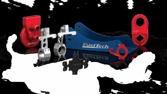
14 Sistemas de injeção eletrônica Accessories Top quality billet Cam Gears and Crank Trigger Systems developed for serious race applications on VW and Opel engines. For general applications please inquire our sales department.


15 Sistemas de injeção eletrônica 14
: +1-973-732-4355 info@fueltechems.")
16 All products are for off road use only. United States: SMAX (New Jersey): Brazil: Porto Alegre, RS
ECUS PERFORMANCE IN YOUR HANDS! SUMMARY CONTROLLERS METERS AND LOGGERS IGNITION SENSORS AND ACCESSORIES FT APPAREL
 207 PERFORMANCE IN YOUR HANDS! FuelTech is an international company specialized in developing and manufacturing state of the art performance engine management systems. The company s elite staff, always
Products Kronenburg Management Systems. kms.vankronenburg.nl
 Products 2011 Kronenburg Management Systems kms.vankronenburg.nl Kronenburg Management Systems (KMS) is a complete line of engine management systems that offers you an extremely reliable and user-friendly
AUTRONIC SM3 ECU Specifications
 AUTRONIC SM3 ECU Specifications Microcomputer Power Supply - Voltage Normal operation Operational limits Intel 16 bit 20MHz 12v to 15v DC 6.2v to 18v DC continuous Power Supply - Current Survival limits
MaxxECU quickstart guide ( )
") Be a tuning mastermind. Like us. MaxxECU quickstart guide (2019-02-01) Online help! maxxecu.com/support Wiring diagrams Installation help Pinout Support maxxecu.com/support Legal disclaimer All performance
Be a tuning mastermind. Like us. MaxxECU quickstart guide (2019-02-01) Online help! maxxecu.com/support Wiring diagrams Installation help Pinout Support maxxecu.com/support Legal disclaimer All performance
2010 Automotive Performance Products Update. Presented by Carl Chastain
 2010 Automotive Performance Products Update Presented by Carl Chastain Subjects Dynojet CMD Master Control Center WB2 Integration / Auto tune What is the Dynojet CMD? The Dynojet CMD is a fuel and boost
smaller. faster. better.
 smaller. faster. better. engine management system in control ENGINE MANAGEMENT Since MoTeC was founded in 1987, the concept has been simple: build a business on the basis of providing quality products
Motronic MS Electronic design. Functionality. Mechanical data. Conditions for use
 Motronic MS 1.10 The MS 1.10 is a highly sophisticated engine management system for high performance engines. The system contains 12 ignition power stages and 24 independent injection power stages. All
Speed-Pro EFI Installation Manual
 Speed-Pro EFI Installation Manual Speed-Pro Electronics Installation Manual Page The wiring harness is labeled on each of the connectors to simplify installation. Your application may not require the use
AUDI ECU for A3, A4, TT (1800 cc) A6 ( cc)
 A6 ( cc)") AUDI ECU for A3, A4, TT (1800 cc) A6 (1800-2000 cc) INTRODUCTION AIM has developed special applications for many of the most common ECUs: by special applications we mean user-friendly systems which allow
AUDI ECU for A3, A4, TT (1800 cc) A6 (1800-2000 cc) INTRODUCTION AIM has developed special applications for many of the most common ECUs: by special applications we mean user-friendly systems which allow
Installation Instructions for: EMS P/N and U Honda S2000
 Installation Instructions for: EMS P/N 30-1052 and 30-1052U 00-04 Honda S2000! WARNING: This installation is not for the tuning novice nor the PC illiterate! Use this system with EXTREME caution! The AEM
Controller Ground (dual black 12awg) should be connected to chassis ground as close as possible to the battery.
 should be connected to chassis ground as close as possible to the battery.") 1. Overview The Maximizer 4 progressive nitrous controller operates one or two separate stages of nitrous based on either time, RPM, MPH, throttle percentage or boost pressure. Whether your engine is naturally
1. Overview The Maximizer 4 progressive nitrous controller operates one or two separate stages of nitrous based on either time, RPM, MPH, throttle percentage or boost pressure. Whether your engine is naturally
View. Capture. Analyze.
 View. Capture. Analyze. The New LM-2 Digital Air/Fuel Ratio Meter and More! Knowledge is Horsepower www.tuneyourengine.com Catalog NOW YOU RE TUNING! At the track, on the street, on the dyno, drag, rally,
M1 GPR-ROTARY PACKAGE
 M1 GPR-ROTARY PACKAGE MoTeC s GPR-Rotary Package is a versatile and adaptable platform for the operation of rotary engines with up to four rotors. This single product can be configured over a huge range
Lingenfelter NCC-002 Nitrous Control Center Quick Setup Guide
 Introduction: Lingenfelter NCC-002 Nitrous Control Center Quick Setup Guide The NCC-002 is capable of controlling two stages of progressive nitrous and fuel. If the NCC-002 is configured only for nitrous,
engine management system
 engine management system in control THE COMPANY MoTeC was founded in 1987 with the aim of providing world class products, superior customer service and the most advanced technology available. A strong
FUEL DELIVERY IGNITION ANGLE CONTROL BOOST CONTROL TECH INFO
 TECH INFO Analogue signal modification with resolution of 0.005V 2 high current outputs (4A each) Adaptive VR sensor input with true zero cross detection Reverse polarity protection Overvoltage protection
Manual - FTSPARK v3 - Capas ENUS.pdf 1 2/16/2017 6:06:34 PM C M Y CM MY CY CMY K OWNER S MANUAL
 OWNER S MANUAL Index 1. Presentation...4 2. Characteristics...5 3. Warranty terms...6 4. Installation...7 4.1 Mounting...7 4.2 Power supply...7 4.3 Harness connections table...8 4.4 Wiring harness installation...
Installation Instructions for: EMS P/N Toyota Supra
 Installation Instructions for: EMS P/N 30-1110 1987-1988 Toyota Supra! WARNING: This installation is not for the tuning novice nor the PC illiterate! Use this system with EXTREME caution! The AEM EMS System
1. Index. LS Wiring Harness. 2. Presentation Warnings and Warranty Terms Overview Labels...7
 OWNER S MANUAL 1. Index 2. Presentation...4 3. Warnings and Warranty Terms...5 4. Overview...6 5. Labels...7 6. Diagrams...7 6.1 FT500/FT500 Aux - Inputs/outputs...7 6.2 Nano WB O2 #1...8 6.3 Nano WB
Installation Instructions for: EMS P/N Ford Mustang 5.0L
 Installation Instructions for: EMS P/N 30-1400 1986-93 Ford Mustang 5.0L! WARNING: This installation is not for the tuning novice nor the PC illiterate! Use this system with EXTREME caution! The AEM EMS
Link Engine Management
 Link Engine Management Designed specifically for Mazda 12A and 13B engines the G4 RX is fully configurable Compared to other rotary ECUs the G4 RX is the clear winner RX Wire-In Rotary Engine Management
DFS-1000 Wiring Diagrams and PC Software Installation.
 DFS-1000 Wiring Diagrams and PC Software Installation. For Technical Support Please contact your dealer or email seellc@mchsi.com 1 Important Information - When using a conventional style ignition coil
QUICK START GUIDE 199R10546
 QUICK START GUIDE 199R10546 1.0 Overview This contains detailed information on how to use Holley EFI software and perform tuning that is included within the software itself. Once you load the software,
Xtreme. Link Engine Management
 Xtreme Link Engine Management The ultimate in engine management. Designed and built to be the best, the Xtreme delivers the results, with more functions than normally demanded by both tuner and driver.
Installation Instructions for: EMS P/N Ford Mustang 5.0L
 Installation Instructions for: EMS P/N 30-1401 1994-95 Ford Mustang 5.0L! WARNING: This installation is not for the tuning novice nor the PC illiterate! Use this system with EXTREME caution! The AEM EMS
1. Index. PRO600 Wiring Harness. 2. Presentation Warnings and Warranty Terms Overview PRO600 Harness...6
 OWNER S MANUAL 1. Index 2. Presentation...4 3. Warnings and Warranty Terms...5 4. Overview...6 4.1 PRO600 Harness...6 5. Versions and components...7 5.1 PRO600 components...7 6. Labels...8 7. Diagrams...9
User and Installation Manual
 User and Installation Manual PE-ECU-1 Engine Control System Revision I, 3/25/2005 For Software Versions 2.051 Copyright 2005, Performance Electronics, Ltd. All Rights Reserved Legal Disclaimer The products
Innovative Racing Electronics
 FOR IMMEDIATE RELEASE Contact: Dan Rudd Phone: 407.330.9727 FAX: 407.322.8632 E-Mail: sales@mpsracing.com Web: www.mpsracing.com Holley Commander 950 Universal 4 Cylinder Fuel Injection Kit Sanford, Florida,
CAUTION: CAREFULLY READ INSTRUCTIONS BEFORE PROCEEDING
 Daytona Sensors LLC Engine Controls and Instrumentation Systems Installation Instructions for WEGO II Wide-Band Exhaust Gas Oxygen Sensor Interface Methanol Version CAUTION: CAREFULLY READ INSTRUCTIONS
PSB-1 User Manual. Warning!
 PSB-1 User Manual Warning! The Oxygen Sensor used in this device gets very hot in operation. Do not touch a hot sensor. Do not let a hot sensor touch a combustible surface. Do not use the sensor with or
Storm. Link Engine Management
 Storm Link Engine Management The G4 Storm delivers performance that rivals any engine management system on the market. This ECU is more than capable of running sequential injection, ignition and variable
MegaSquirt III for Gen 3 HEMI. Hardware Install THE FOLLOWING SENSOR PART NUMBERS APPLY TO ALL HARNESSES FOR ENGINES 2004 TO CURRENT:
 MegaSquirt III for Gen 3 HEMI MegaSquirt controllers are experimental devices intended for educational purposes. MegaSquirt controllers are not for sale or use on pollution controlled vehicles. Check the
KMS MD35 Communication protocol Release 1.02 KMS MD35 ECU.
 KMS MD35 ECU 1 INTRODUCTION AIM has developed special applications for many of the most popular ECUs: by special applications we mean user-friendly systems which allow to easily connect your ECU to our
POLESTAR HS Management System
 POLESTAR HS Management System Installation Instructions This document contains the information needed to install and adjust the POLESTAR HS Engine Management System. It assumes that the system already
CAUTION: CAREFULLY READ INSTRUCTIONS BEFORE PROCEEDING
 Daytona Sensors LLC Engine Controls and Instrumentation Systems Installation Instructions for Wide-Band Exhaust Gas Oxygen Sensor Interface CAUTION: CAREFULLY READ INSTRUCTIONS BEFORE PROCEEDING OVERVIEW
GENERAL MOTORS SERVICE PARTS OPERATION 6200 Grand Pointe Drive, Grand Blanc, MI 48439
 LS IGNITION CONTROLLER 19355418 Ignition Control for Carbureted LS Series Engines (24x Crankshaft Index/1x Camshaft Index, 58x Crankshaft Index/4x Camshaft Index) Parts Included Quantity Ignition Controller
RaceROM Features Subaru FA20 DIT
 RaceROM Features Subaru FA20 DIT v1.11 Contents CAUTION!... 3 INTRODUCTION... 4 Feature list... 4 Supported Vehicle Models... 4 Availability... 4 OVERVIEW... 5 Map Switching... 5 Boost Controller... 5
Glossary. 116
 Sequential Fuel Injection Sequential means that each injector for each cylinder is triggered only one time during the engine s cycle. Typically the injector is triggered only during the intake stroke.
Getting Started... 7 Setting the ECU parameters for a specific engine... 7 Auxiliaries... 7 Output Control circuits... 7 Engine Tuning...
 Getting Started... 7 Setting the ECU parameters for a specific engine... 7 Auxiliaries... 7 Output Control circuits... 7 Engine Tuning... 8 Tune Analyser... 8 Data Logging... 8 Wiring Diagrams... 8 ECU
VIEW. CAPTURE. ANALYZE. CONTROL.
 VIEW. CAPTURE. ANALYZE. CONTROL. The INNOVATE MOTORSPORTS Difference. DirectDigital O2 Control for 2017! Increased analog output speed! 4 ms response time helps ensure that your ECU sees changes in Air/Fuel
Marelli MF4M ECU Technical documentation Release 1.01 INTRODUCTION logger Race Studio 2
 MARELLI MF4M ECU INTRODUCTION AIM has developed special applications for many of the most popular ECUs; by special applications we mean user-friendly systems which allow to easily connect your ECU to our
Setup Tabs. Basic Setup: Advanced Setup:
 Setup Tabs Basic Setup: Password This option sets a password that MUST be entered to re-enter the system. Note: ProEFI can NOT get you into the calibration if you lose this password. You will have to reflash
Installation Instructions for: EMS P/N Acura Integra Acura 2.3CL Honda Accord Honda Civic
 ! Installation Instructions for: EMS P/N 30-1010 00-01 Acura Integra 98-99 Acura 2.3CL 98-02 Honda Accord 99-00 Honda Civic WARNING: This installation is not for the tuning novice nor the PC illiterate!
RF Fiberglass lightweight bodykit RF Improved cooling flow and intake RF adjustable rear wing EXTERIOR & AERO
 RF Fiberglass lightweight bodykit RF Improved cooling flow and intake RF adjustable rear wing EXTERIOR & AERO BODYKIT Fiberglass front fender Bonnet with carbon fiber vent Fiberglass front bumper Carbon
CAUTION: CAREFULLY READ INSTRUCTIONS BEFORE PROCEEDING
 Daytona Sensors LLC Engine Controls and Instrumentation Systems Installation Instructions for WEGO IIID Wide-Band Exhaust Gas Oxygen Sensor Interface (Automotive Version) CAUTION: CAREFULLY READ INSTRUCTIONS
SimMotor User Manual Small Engine Simulator and HIL V COPY RIGHTS ECOTRONS LLC All rights reserved
 V2.3.1 SimMotor User Manual Small Engine Simulator and HIL V2.3.1 COPY RIGHTS ECOTRONS LLC All rights reserved Http://www.ecotrons.com Table of Contents Read before you start:...1 Why do I need SimMotor?...2
AiM Infotech. Bosch MS43 GA and Bosch MS43 Clubsport ECU. Release 1.02
 AiM Infotech Bosch MS43 GA and Bosch MS43 Clubsport ECU Release 1.02 1 Supported models This tutorial explains how to connect Bosch MS43 ECU to AiM devices. Supported models are: Bosch MS43 GA Bosch MS43
INSTALLATION INSTRUCTIONS. Revision 3.1.1
 INSTALLATION INSTRUCTIONS Revision 3.1.1 Table of Contents INTRODUCTION... 4 INSTALLATION OVERVIEW... 5 Included Parts... 6 DEVICE WIRING... 7 Required Parts... 7 Guidelines... 7 Wiring Diagram... 8 Compatible
1. Overview. 2. MAX 5 hardware installation
 1. Overview The Maximizer 5 progressive controller operates up to four separate stages of nitrous or water methanol based on either time, RPM, MPH, throttle percentage or boost pressure. Whether your engine
RF Fiberglass lightweight bodykit RF Improved cooling flow and intake RF adjustable rear wing EXTERIOR & AERO
 RF Fiberglass lightweight bodykit RF Improved cooling flow and intake RF adjustable rear wing EXTERIOR & AERO BODYKIT Fiberglass front fender Bonnet with carbon fiber vent Fiberglass front bumper Carbon
SP4 DOCUMENTATION. 1. SP4 Reference manual SP4 console.
 SP4 DOCUMENTATION 1. SP4 Reference manual.... 1 1.1. SP4 console... 1 1.2 Configuration... 3 1.3 SP4 I/O module.... 6 2. Dynamometer Installation... 7 2.1. Installation parts.... 8 2.2. Connectors and
MegaSquirt III for LS Style Engines. Hardware Install. 1. Disconnect and remove the battery from the vehicle.
 MegaSquirt III for LS Style Engines MegaSquirt controllers are experimental devices intended for educational purposes. MegaSquirt controllers are not for sale or use on pollution controlled vehicles. Check
Subaru MY07 - MY15 STi/WRX Plug-in Manual
 Subaru MY07 - MY15 STi/WRX Plug-in Manual February 2016 Table of Contents 1.0 Introduction... 3 2.0 Expansion Loom... 4 3.0 ECU Channel Assignments... 5 4.0 Plug-in Specific Information... 8 4.1 Fuel Model...
HP and Dominator Component Selection Guide. Use when building Dominator Systems or Custom HP Systems. Step 2 (notes) Choose Your Main Harness
 Choose Your Main Harness") HP and Dominator Component Selection Guide Use when building Dominator Systems or Custom HP Systems Step 1 (required) Choose your ECU & Main Power Harness Step 2 (notes) Choose Your Main Harness Step 3
HP and Dominator Component Selection Guide Use when building Dominator Systems or Custom HP Systems Step 1 (required) Choose your ECU & Main Power Harness Step 2 (notes) Choose Your Main Harness Step 3
Atom. Link Engine Management
 Atom Link Engine Management The all new G4 Atom is your entry level ECU that blows the opposition away. Full configurability, no preset input/outputs. Logging, motor-sport, even closed loop fuel and knock
ProECU EVO X. Tuning Guide 2008-onward Model Year. v1.8
 ProECU EVO X Tuning Guide 2008-onward Model Year v1.8 Contents ECU Map Descriptions... 3 3D Maps... 3 Fuel Maps Shown in Live Data as Injector % and Injector ms... 3 High Octane... 3 Low Octane... 3 Ignition
ENGINE MANAGEMENT SYSTEM. System Sensors
 ENGINE MANAGEMENT SYSTEM System Sensors Throttle position sensor - Used to relay throttle position information to the ECU. Throttle opening angle is used by the ECU to determine fuelling and ignition requirements
Ferrari F430 Challenge ECU connection
 Ferrari F430 Challenge ECU connection INTRODUCTION Ferrari 430Challenge ECU Conneciton AIM has developed special applications for many of the most common ECUs: by special applications we mean user-friendly
This product is legal in California for racing vehicles only and should never be used on public highways.
 Installation Instructions for: EMS P/N 30-1602 and 30-1602U 96-99 Nissan 180SX SR20DET 97-98 Nissan Silvia S14 SR20DET 93-98 Nissan Silvia S14 SR20DET (Europe) 99-02 Nissan Silvia S15 SR20DET! WARNING:
Installation Instructions for: EMS P/N Dodge Viper V-10
 Installation Instructions for: EMS P/N 30-1500 1996-02 Dodge Viper V-10! WARNING: This installation is not for the tuning novice nor the PC illiterate! Use this system with EXTREME caution! The AEM EMS
AiM User Guide. MecTronic MKE1. Release 1.00
 AiM User Guide MecTronic MKE1 Release 1.00 1 Supported models This user guide explains how to connect MekTronik ECU to AiM devices. Supported model is: MekTronik MKE1 2 Wiring connection MecTronik MKE1
CATALOG OFF ROAD&ATV - ROAD - SPORT BIKE - AUTOSPORT.
 CATALOG OFF ROAD&ATV - ROAD - SPORT BIKE - AUTOSPORT OFFROAD MAYA programming software GP1-EVO Ecu MAYA is a powerful tool allowing real-time setting of the engine data while displaying all variables for
CAUTION: CAREFULLY READ INSTRUCTIONS BEFORE PROCEEDING
 Daytona Sensors LLC Engine Controls and Instrumentation Systems Installation Instructions for Wide-Band Exhaust Gas Oxygen Sensor Interface CAUTION: CAREFULLY READ INSTRUCTIONS BEFORE PROCEEDING OVERVIEW
Installation Instructions for: EMS P/N Toyota Supra
 Installation Instructions for: EMS P/N 30-1130 1989-1992 Toyota Supra! WARNING: This installation is not for the tuning novice nor the PC illiterate! Use this system with EXTREME caution! The AEM EMS System
GENERAL ANDROID DEVICE RECOMMENDATIONS
 GENERAL ANDROID DEVICE RECOMMENDATIONS The Edelbrock EFI E-Tuner app is compatible with most Android based Smartphones and tablets operating on Android 5.0 and later. However, due to slight variations
ProMax Progressive Controller Installation and Operation Instructions
 ProMax Progressive Controller Installation and Operation Instructions These instructions will guide you through the setup, installation, and use of the Nitrous Outlet Promax Progressive Controller. If
DD2-PRO+ Gps enabled Datalogger & display system mm (W) x 90mm (H) x 28mm (D) Datalogger Front 109mm (W) x 35mm (H) x 121mm (D) Datalogger Back
 x 90mm (H) x 28mm (D) Datalogger Front 109mm (W) x 35mm (H) x 121mm (D) Datalogger Back") DD2-PRO+ Gps enabled Datalogger & display system PRO Display - 160.4mm (W) x 90mm (H) x 28mm (D) Datalogger Front 109mm (W) x 35mm (H) x 121mm (D) Datalogger Back Feature Summary Display Programmable Speed
DD2-PRO+ Gps enabled Datalogger & display system PRO Display - 160.4mm (W) x 90mm (H) x 28mm (D) Datalogger Front 109mm (W) x 35mm (H) x 121mm (D) Datalogger Back Feature Summary Display Programmable Speed
Core Harness System Crank/Cam Adapter Harness FAST Dual Sync Distrubutor 35" STOP!
 Instruction Manual 30-3805-20 Core Harness System Crank/Cam Adapter Harness FAST Dual Sync Distrubutor 35" STOP! THIS PRODUCT HAS LEGAL RESTRICTIONS. READ THIS BEFORE INSTALLING/USING! THIS PRODUCT MAY
Error codes Diagnostic plug Read-out Reset Signal Error codes
 Error codes Diagnostic plug Diagnostic plug: 1 = Datalink LED tester (FEN) 3 = activation error codes (TEN) 4 = positive battery terminal (+B) 5 = ground Read-out -Connect LED tester to positive battery
ELECTRONIC TRACTION CONTROL USER MANUAL
 DRAG-SPORTSMAN N2O For ELECTRONIC TRACTION CONTROL USER MANUAL TELEPHONE 828.645.1505 FAX 828.645.1525 WWW.MORETRACTION.COM US PATENT 6,577,944 Disclaimer...2 Introduction... 3 How Does It Work. 4 Installation...
Pectel T2 ECU Technical documentation Release 1.00 INTRODUCTION
 Pectel T2 ECU Pectel T2 INTRODUCTION AIM has developed special applications for many of the most popular ECUs: by special applications we mean user-friendly systems which allow to easily connect your ECU
Installation Instructions for: EMS P/N Toyota MR2 Turbo Toyota Celica All Trac
 Installation Instructions for: EMS P/N 30-1120 1991-1992 Toyota MR2 Turbo 1990-1992 Toyota Celica All Trac! WARNING: This installation is not for the tuning novice nor the PC illiterate! Use this system
Gen III HEMI Harness PN or
 Gen III HEMI Harness PN 558-106 or 558-107 This wiring harness interfaces a Holley EFI ECU to a Gen III HEMI engine. It is meant to be used in conjunction with an injector harness, a coil harness, and
Automotive Application ET01 Software Revision A 12/06
 Automotive Application ET01 Software Revision A 12/06 INTRODUCTION... 2 FUNCTIONAL DESCRIPTION... 3 INSTALLATION... 4 COMPONENT PLACEMENT... 4 PLUMBING AND WIRING... 5 MSBC OPERATION (ET-01)... 14 TIMED
The Aftermarket EFI buyer s guide, courtesy of
 The Aftermarket EFI buyer s guide, courtesy of www.efisupply.com We often receive inquiries from customers asking which aftermarket electronic fuel injection system is the best one. Rather than steering
SCHNITZ MOTORSPORTS USER MANUAL AND INSTALLATION GUIDE PRO-MOD BATTERY VOLTS DIAGNOSTICS NOS PULSE FREQUENCY NOS DELAY TIME IN SECONDS
 SCHNITZ MOTORSPORTS DSC-CS "PRO-MOD" IGNITION CONTROLLER USER MANUAL AND INSTALLATION GUIDE COIL, (OPTIONAL) GA YELLOW, COIL, NEGATIVE GA WHITE, GA BLACK, SHIFT LIGHT +V OUTPUT PAGE 0 NOS ACTIVATION INPUT
Motronic September 1998
 The Motronic 1.8 engine management system was introduced with the 1992 Volvo 960. The primary difference between this Motronic system and the previous generation of Volvo LH-Jetronic engine management
MAX-FIRE AND E-FIRE ELECTRONIC DISTRIBUTORS
 INSTALLATION INSTRUCTIONS MAX-FIRE AND E-FIRE ELECTRONIC DISTRIBUTORS NOTE: This product is applicable to pre-1966 California and pre-1968 federally certified passenger cars. It is also applicable to non-emission
Copyright Nistune Developments rev4
 Copyright Nistune Developments 2014-2017 rev4 Boost Sensor Register Nissan has added an additional boost sensor to the Nissan ECU: Boost pressure sensor. Uses a vaccum/boost equipped MAP sensor capable
FLY BY WIRE SETTINGS 31 August 2016
 FLY BY WIRE SETTINGS: Entries in red, except for charts (18 September 2014) GROUPS/OUTPUT FUNCTIONS/FBW: FBW Enabled: ENABLED FBW Control Frequency: 5000Hz (13Hz to 10000Hz) FBW Control Minimum Duty: -100%
CAUTION: CAREFULLY READ INSTRUCTIONS BEFORE PROCEEDING
 Daytona Sensors LLC Engine Controls and Instrumentation Systems Installation Instructions for Wide-Band Exhaust Gas Oxygen Sensor System CAUTION: CAREFULLY READ INSTRUCTIONS BEFORE PROCEEDING OVERVIEW
Wide Band Air Fuel Ratio meter (Bosch LSU 4.9 sensors)
") Wide Band Air Fuel Ratio meter (Bosch LSU 4.9 sensors) Overview- Air Fuel Ratio (AFR) meter & display Interfaces to DYNertia3 or data loggers, It can also be used as a rugged professional stand-alone unit.
Wide Band Air Fuel Ratio meter (Bosch LSU 4.9 sensors) Overview- Air Fuel Ratio (AFR) meter & display Interfaces to DYNertia3 or data loggers, It can also be used as a rugged professional stand-alone unit.
ENGINE CONTROL SYSTEM. 1. General ENGINE 3VZ FE ENGINE
 ENGINE 3VZ FE ENGINE 69 ENGINE CONTROL SYSTEM 1. General The engine control system for the 3VZ FE engine has the same basic construction and operation as for the 2VZ FE engine. However, the sequential
SP5 INSTALLATION AND SETUP MANUAL
 SP5 INSTALLATION AND SETUP MANUAL 1 Installation 1.1 Introduction The SP5 System consists of a Data Acquisition unit (DAQ) with two complete Roller control channels, each Roller Control Channel consists
Parts Catalogue. Revision 1.24
 Parts Catalogue Revision 1.24 February 2007 Contents Introduction... 4 MoTeC Engine Control Units... 5 M4 CLUBMAN ECU... 5 M48 CLUBMAN ECU... 7 M2R / MLS ECU... 9 M400 ECU... 10 M600 ECU... 12 M800 ECU...
E-STREET 2 EFI IGNITION CONTROL KIT Part #3674, 3675, 3676, 3679, 3680 INSTALLATION INSTRUCTIONS
 E-STREET 2 EFI IGNITION CONTROL KIT Part #3674, 3675, 3676, 3679, 3680 INSTALLATION INSTRUCTIONS PLEASE study these instructions carefully before beginning this installation. Most installations can be
for First Generation DSM and 3000GT/Stealth Version 1.0
 for First Generation DSM and 3000GT/Stealth Version 1.0 Table of Contents: Kit Contents Available Accessories Description Special features Installation Operation Configurable display features Clear Codes
Common rail injection system
 Common rail injection system Pressure limiting valve The pressure limiting valve is located directly on the high-pressure fuel rail. Its function is to limit maximum pressure in the high-pressure fuel
AiM Infotech. Bosch MS4.3 Grand Am and Bosch MS4.3 Turbo ECU. Release 1.01
 AiM Infotech Bosch MS4.3 Grand Am and Bosch MS4.3 Turbo ECU Release 1.01 This tutorial explains how to connect Bosch MS4.3 ECU to AiM devices. Supported years and models are: Bosch MS4.3 Grand Am 2011
Crank Trigger Hardware Installation
 Crank Trigger Hardware Installation Step 1 - Bring the engine up to TDC and remove the crank pulley bolt. Step 2 - Install trigger wheel making sure to line up the keyway. You may need to use the bolt
XMS4C DIY MANUAL. Engine Management System. Version 2.0
 XMS4C Engine Management System DIY MANUAL Version 2.0 Table of Contents: Page no: 1. INTRODUCTION...1 2. PARTS SUPPLIED IN THE KIT...1 3. WHY SHOULD YOU READ THIS MANUAL?...1 4. EXPLANATION OF XMS4 UNITS
With PRO+ Datalogger:- Lambda (Air/Fuel Ratio)* Turbo Boost* Brake Pressure Front & Rear +Brake Bias*
* Turbo Boost* Brake Pressure Front & Rear +Brake Bias*") DD2-SS 240MM Ø Steering Wheel display & Datalogging system 240mm Diameter steering wheel supplied with quick release boss and spline. (Paddles not included) Datalogger Front 109mm (W) x 35mm (H) x 121mm
DD2-SS 240MM Ø Steering Wheel display & Datalogging system 240mm Diameter steering wheel supplied with quick release boss and spline. (Paddles not included) Datalogger Front 109mm (W) x 35mm (H) x 121mm
3. Engine Control System Diagram
 ENGINE - 2UZ-FE ENGINE 59 3. Engine Control System Diagram Ignition Switch Fuel Pump Relay Fuel Pump Resister Circuit Opening Fuel Relay Filter Intake Temp. Mass Air Flow Meter Throttle Position Fuel Pump
ELITE 1000/1500 Dodge SRT QUICK START GUIDE HT
 E N G I N E M A N A G E M E N T S Y S T E M S ELITE 1000/1500 Dodge SRT4 03-05 QUICK START GUIDE HT-140940 LIMITED WARRANTY Lockin Pty Ltd trading as Haltech warrants the HaltechTM Programmable Fuel Injection
CAUTION: CAREFULLY READ INSTRUCTIONS BEFORE PROCEEDING
 Twin Tec Installation Instructions for Wide-Band Exhaust Gas Oxygen Sensor System CAUTION: CAREFULLY READ INSTRUCTIONS BEFORE PROCEEDING OVERVIEW The is a complete air/fuel ratio (AFR) metering system
POWERSPORTS DYNAMOMETER HARDWARE AND SOFTWARE
 POWERSPORTS DYNAMOMETER HARDWARE AND SOFTWARE DYNOWARE RT DYNAMOMETER HARDWARE DYNOWARE RT THE NEXT GENERATION OF DYNOJET DYNAMOMETER ELECTRONICS AND SOFTWARE HAS ARRIVED. DynoWare RT is the next generation
Preparing and programming of ESGI 2 LPG supply system manual
 Preparing and programming of ESGI 2 LPG supply system manual Part II Instruction of preparing and programming the ESGI system 1 Technical data of the central unit Vs Power supply voltage 0...16V V i_an
Installation Guide. Thank you for the purchase of our product. You have just unleashed infinite control, power and ability into your hands.
 Installation Guide Thank you for the purchase of our product. You have just unleashed infinite control, power and ability into your hands. This product is for race use only by experienced engine tuners.
Manual - FT600 v4 - Capas ENUS.pdf 1 2/15/2017 6:14:14 PM C M Y CM MY CY CMY K OWNER S MANUAL
 OWNER S MANUAL FT600 1. index 2. Presentation... 5 3. Warranty terms... 6 4. Characteristics... 7 4.1 Harness connections Aconnector... 9 4.2 Harness connections Bconnector...11 4.3 Output table of FT600...12
WOLF3D. Installation Manual. Version 4.57 Engine Management System with WIDEBAND AFR. Revision Number 1.004
 WOLF3D Version 4.57 Engine Management System with WIDEBAND AFR Installation Manual Revision Number 1.004 Printed January 27, 2016 CONTENTS 1 Introduction... 5 2 ECU... 6 2.1 Mounting the ECU... 6 2.2 Diagnostic