1. Index. PRO600 Wiring Harness. 2. Presentation Warnings and Warranty Terms Overview PRO600 Harness...6
|
|
|
- Jack Robinson
- 5 years ago
- Views:
Transcription


1 OWNER S MANUAL
2
3 1. Index 2. Presentation Warnings and Warranty Terms Overview PRO600 Harness Versions and components PRO600 components Labels Diagrams PRO600 diagrams Main engine(37-way CPC connector) Connectors Firewall Circular Connector Relay and Fuses Crank Trigger and Cam Sync sensor TPS H2O and Air Temperature Oil, Fuel and Wastegate Pressure Points Injectors Back Pressure Extra Connections Standard Sensors Fuel and Oil Pressure Intake Air Temperature Engine Temperature Meters and adapter wires Fuel Tech WB-O2 Nano Alcohol O Bosch LSU 4.2 Wideband O2 Sensor NTK WB-O2 sensor - Alcohol Bosch LSU 4.2 O2 sensor to Alcohol O WB-O2 sensor Bosch to NTK adapter harness Peak and Hold - External Injector Driver Troubleshooting FuelTech Latest Manuals and Software
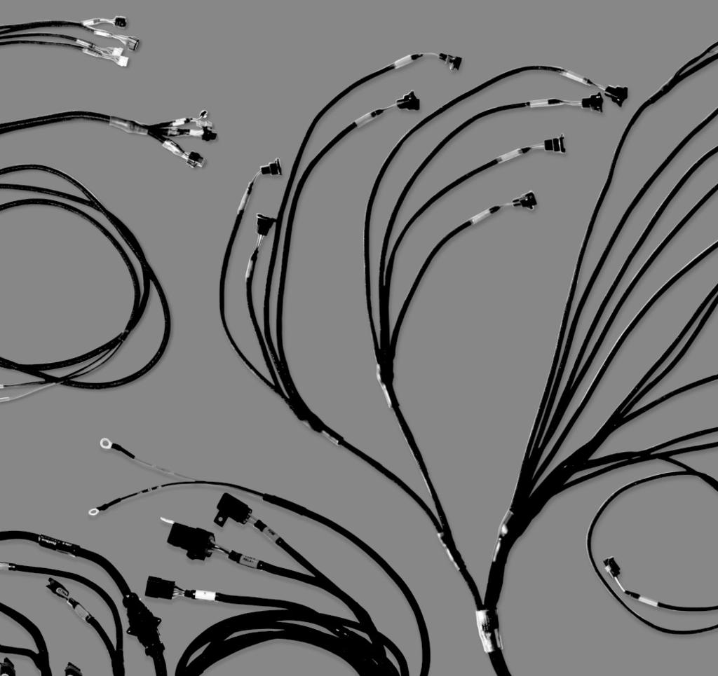
4 2. Presentation The FuelTech PRO600 harness is the proper link between the FuelTech FT600 ECU and all of your engine sensors and actuators. This harness has all the components needed to make a plug n play installation on an engine. It has all the relays and fuses needed for the system on a standard setup, a firewall connector to make it easier to remove and every connector has its own label. The insulation and connectors are humidity, heat and oil resistant. Specifications: - 8 or 16 injector outputs(for 16 injectors a secondary injector harness is required) - 2 FuelTech Peak and Hold external drivers ready - Dual FuelTech WB-Nano O2 ready - FuelTech Alcohol O2 dual channel (Adapter harness required) - GM Style intake air temperature sensor ready - GM Style engine temperature sensor ready - 4 pressure sensor ready for fuel, oil wastegate and backpressure/another 0-5V sensor - High output relays - 3 Extra output connectors for generic use. - 1 Extra Inputs connector for generic use. - Firewall CPC Connector - Crank and Cam connectors (hall and VR options) Dimensions (in package): 20 x 20 x 5 Weight: 11 lbs. 4
5 3. Warnings and Warranty Terms The use of this equipment implies in total accordance with the terms described in this manual and exempts the manufacturer from any responsibility regarding to product misuse. Read all the information in this manual before starting the product installation. This product must be installed and tuned by specialized auto shops and/or personnel with experience on engine tuning. Limited Warranty All products manufactured by FUELTECH are warranted to be free from defects in material and workmanship for one year following the date of original purchase. Warranty claim must be made by original owner with proof of purchase from an authorized reseller. This warranty does not include sensors or other products that FUELTECH carries but did not manufacture. If a product is found defective, such products will, at FUELTECH s option, be replaced or repaired at no cost. All products alleged by Purchaser to be defective must be returned to FUELTECH, postage prepaid, within the one year warranty period. Before starting any electrical installation, disconnect the battery. The inobservance of any of the warnings or precautions described in this manual might cause engine damage and lead to the invalidation of this products warranty. The improper adjustment of the product might cause engine damage. This product does not have a certification for the use on aircrafts or any flying vehicles, as it was not designed for such use or purpose. In some countries where an annual inspection of vehicles is enforced, no modification in the OEM ECU is permitted. Be informed about local laws and regulations prior to the product installation. This limited warranty does not cover labor or other costs or expenses incidental to the repair and/or replacement of products or parts. This limited warranty does not apply to any product which has been subject to misuse, mishandling, misapplication, neglect (including but not limited to improper maintenance), accident, improper installation, tampered seal, modification (including but not limited to use of unauthorized parts or attachments), or adjustment or repair performed by anyone other than FUELTECH. The parties hereto expressly agree that the purchaser s sole and exclusive remedy against FUELTECH shall be for the repair or replacement of the defective product as provided in this limited warranty. This exclusive remedy shall not be deemed to have failed of its essential purpose so long as FUELTECH is willing and able to repair or replace defective goods. FUELTECH reserves the right to request additional information such as, but not limited to, tune up and log files in order to evaluate a claim. Seal violation voids warranty and renders loss of access to update releases. Manual version 1.0 March/2017 5


. 4.")


, distributor")


6 4. Overview The FuelTech is a complete plug n play wiring solution to be used with a FuelTech FT600 ECU. It has all the connectors, relays and fuses directly built-in and can be used with nearly any application with 8 injectors (expandable up to 16 injectors). 4.1 PRO600 Harness The PRO600 is a FuelTech FT600 harness designed for systems with up to 16 staged injectors(dual banks), distributor or COP coils and FuelTech Wideband Nano O2 dual channel with Bosch LSU 4.2 sensors to run sequential, semi-sequential or multipoint injection. It is already wired for 2 FuelTech Peak and Hold drivers for setups utilizing 8 low impedance injectors, for 8 more injectors a secondary injector harness is required. When using high impedance injectors, Peak and Holds are not needed. In this case, only a bypass connector (jumper wires sold separately) is required. There are 2 relays to power the complete system, separating the injectors from the electronics Connector A, B and CAN of FT600; 2 - Relays and fuse; 3 - Auxiliars connectors; 6

 - CAN A and CAN B Connectors: CAN A receives any other FuelTech module that")


 goes directly to the battery s positive or kill switch.")

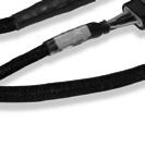
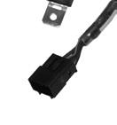
7 5. Versions and components To make it easier to install and to do services in the engine/car, the PRO600 Harness is modular, so you can disconnect the engine side of the harness from the rest of it. Below are all of the parts contained in the basic version: 5.1 PRO600 components Main/Outputs (Inner) - CAN A and CAN B Connectors: CAN A receives any other FuelTech module that communicates through CAN ports. CAN B is used to eliminate the Racepak interface module. - Aux Power: Power output straight from the battery to connect with secondary injector harness. - Output Connectors: Outputs A has 8 blue wires to use as general output or to connect to secondary injector harness. Outputs B has 8 gray wires to use as general output or to connect to coil harness. Outputs C has 8 yellow wires to use as general outputs. - Inputs Connector: Inputs connector has 13 white wires to use as general inputs for 0 to 5V analog sensors. - Main Inner 37-way circular: The Main connector is a 37-way Tyco CPC connector which contains all necessary inputs to run an engine. This connector can be attached to the fi rewall. Main Engine This is the section that will be installed in the inner side of the car. On this part you will fi nd the connections to all the units, the wires related to the power supply (+12V to battery, ground to battery, ground to chassis, +12V switched), relays and fuses. Check below to see all of the connectors and where they are connected: - FuelTech FT600 A and B connectors: Direct connection to FT600, both connectors must be securely installed. - 2x FuelTech Peak and Hold: These are the driver modules needed to fi re low impedance injectors. When the system uses high impedance injectors, jumper wires are required (sold separately). If the Peak and Hold or the jumper wires are not being used, the injectors will not fi re. - FuelTech Wideband Nano O2 dual channel: This connector goes to the FuelTech Wideband Nano O2 module, it s capable of reading the Bosch O2 sensors and send the information to log in the FT x 40A Relay: The system has 2 relays to power everything. The Main Relay powers the ECU, Wideband Nano O2, Peak and Hold drivers, sensors and Outputs B connector. The Injector Relay powers only the primary injectors V Switched wire: This wire goes to the ignition key and is responsible for turning on all the relays. - Battery ground and battery positive: It is the system power supply and must be connected exactly as the following: Battery (+) goes directly to the battery s positive or kill switch. Battery (-) MUST GO ONLY on the battery s negative terminal. - Female 37-way circular connector: The Main connector is a 37-way Tyco CPC connector which contains all necessary inputs to run an engine. There you will fi nd the following connectors: O2 sensors, Crank Trigger Sensor, Cam Sync Sensor, TPS, Oil Pressure, Fuel Pressure, Wastegate Pressure, Points, Engine Temperature, Intake Air Temperature, Back Pressure or any 0-5V sensor and the 8 injectors. - Throttle position sensor: The TPS measures the throttle position. The PRO600 harness has a 3-way Weather Pack connector and almost any 0-5V TPS can be used. - Back pressure sensor: This input can be used to read the back pressure, any other pressure with a FuelTech PS sensor or any 0-5V sensor. It also can read an external MAP sensor. - Points (ignition output): Points is the ignition output to fi re a MSD ignition box or other ignition modules in a distributor system. 7


: PRO600")
 and Cherry")

 and Cherry")


 which")


: 8 injector - Main Inner")


8 - Fuel pressure sensor: This input can be used to read fuel pressure using a FuelTech PS sensor or SSI P51 Packard sensor. - Outputs A connector: This connector must be plugged on the Outputs A connector on the PRO600 harness. - Oil pressure sensor: This input can be used to read oil pressure using a FuelTech PS sensor or SSI P51 Packard sensor. - Crank trigger sensor (Hall effect or variable reluctance): PRO600 harness is ready for both MSD crank trigger (VR) and Cherry GS Hall effect sensor. - Cam sync sensor (Hall effect or variable reluctance): PRO600 harness is ready for both Pro Mag 44 trigger (with mods) and Cherry GS Hall effect sensor. - Engine temperature sensor: Ready for GM style CLT sensor. - Intake air temperature sensor: Ready for GM style IAT sensor. - 2x Bosch wideband O2 sensors: Designed for Bosch LSU 4.2 O2 sensors. - 8x fuel Injector outputs (primary bank): 8 injector outputs (EV1 connector) which allows sequential fuel injection and individual fuel cylinder trim. PRO600 Secondary injectors extension harness components - 8x fuel injector outputs (secondary bank): 8 injector outputs (EV1 connector) which allows sequential fuel injection and individual fuel cylinder trim. - Main Inner 24-way circular: The Main connector is a 24-way Tyco CPC connector which contains the outputs to the additional 8 injectors. This connector can be attached to the fi rewall. PRO600 Individual coils extension harness components This extension allows the use of 8 individual COP coils on the ignition system, it has 8 metri-pack connectors, a relay and a fuse. Check below to see all of the connectors and where they are connected: - 1x 30A Relay: This Relay will power the coils. - Outputs B connector: This connector must be plugged on the Outputs B connector on the PRO600 harness. - Main Inner 24-way circular: The Main connector is a 24-way Tyco CPC connector which contains the outputs to the 8 individual coils. - 8x IGN-1 coil connectors: 8 COP coil outputs (IGN-1 standard connector) which allows either sequential or Metri-Pack connectors wasted spark ignition. This is the extension harness required to run a secondary bank of injectors. It has 8 additional injector and 2 additional peak and hold connectors, a relay and a fuse. Check below to see all of the connectors and where they are connected: - 2x FuelTech Peak and Hold: These are the driver modules needed to fi re low impedance injectors. When using high impedance injectors, jumper wires are required (sold separately). If the Peak and Hold or the jumper wires are not being used, the injectors will not fi re. - 1x 30A Relay: This Relay will power the injectors. - Aux Power: This connector goes to the Aux Power on the PRO600 harness and is responsible for turning on the relay. 6. Labels All connectors have proper labels to identify each one. They are labeled by color and description name. The colors are related to their functions: - Green: The green labels are related to the RPM sensors (Crank Trigger and Cam Sync) - Yellow: Input sensors such as TPS, Engine Temp, Air temp, Fuel Pressure, Oil Pressure, Back Pressure or any other 0-5V sensor - Blue: Exclusively to O2 sensors (NTK or Bosch) - White: Outputs and Extra connector, Points, CAN - Purple: Peak and Hold and fuel injectors (Primary bank) - Brown: Peak and Hold and fuel injectors (Secondary bank) - Black: FT600, Main connector, Battery (-), Power Ground - Red: Battery (+), Main and Injectors relays/fuses 8
9 7. Diagrams 7.1 PRO600 diagrams Conector A PRO600 FT600 #Pin Wire color #Pin Connector Function 1 Blue #1 4 Peak and Hold (L) #1 injector 2 Blue #2 4 Peak and Hold (R) #2 injector 3 Blue #3 2 Peak and Hold (L) #3 injector 4 Blue #4 2 Peak and Hold (R) #4 injector 5 Blue #5 5 Peak and Hold (L) #5 injector 6 Blue #6 5 Peak and Hold (R) #6 injector 7 Blue #7 1 Peak and Hold (L) #7 injector 8 Blue #8 1 Peak and Hold (R) #8 injector 9 Blue #9 A Outputs A Generic output #1 10 Blue #10 B Outputs A Generic output #2 11 Blue #11 C Outputs A Generic output #4 12 Blue #12 D Outputs A Generic output #5 13 Blue #13 E Outputs A Generic output #6 14 Blue #14 F Outputs A Generic output #7 15 Blue #15 G Outputs A Generic output #7 16 Blue #16 H Outputs A Generic output #8 17 Black/white - Power Ground Power Ground 18 Grey #1 A Outputs B Generic output #1 19 Grey #2 B Outputs B Generic output #2 20 Grey #3 C Outputs B Generic output #3 21 Grey #4 D Outputs B Generic output #4 22 Grey #5 E Outputs B Generic output #5 23 Grey #6 F Outputs B Generic output #6 24 Grey #7 G Outputs B Generic output #7 25 Grey #8 H Outputs B Generic output #8 26 Yellow #1 A / 2 Outputs C / Points Points / Generic output #1 27 Yellow #2 B Outputs C Generic output #2 28 Yellow #3 C Outputs C Generic output #3 29 Yellow #4 D Outputs C Generic output #4 30 Yellow #5 E Outputs C Generic output #5 31 Yellow #6 F Outputs C Generic output #6 32 Yellow #7 G Outputs C Generic output #7 33 Yellow #8 H Outputs C Generic output #8 34 Red 87 Main Relay Switched W #2 9
10 Conector B PRO600 FT600 #Pin Wire color #Pin Connector Function Red (VR)/White (Hall) Shielded black cable- crank Black Shielded black cable crank Red (VR)/White (Hall) Shielded grey cable cam Black Shielded grey cable cam 2/B Crank VR/Hall RPM input - positive signal 1 Crank VR RPM input - negative signal B/B Cam VR/Hall Cam sync input - positive signal A Cam VR Cam Sync input - negative signal 5 White #1 A Inputs Generic input #1 6 White #2 C Back Pressure BACK PRESSURE input 7 White #3 B Inputs Generic Input #3 8 White #4 C Oil Pressure Oil pressure input 9 White #5 A H2O Coolant Temperature Input 10 Black - Battery (-) Ground 11 Yellow/Blue 3 CAN_A CAN_A_LOW 12 White/Red 4 CAN_A CAN_A_HI 13 White #6 C Fuel Pressure Fuel pressure input 14 White #7 A Air Temperature Air temperature input 15 White #8 C Inputs Generic input #8 16 White #9 D Inputs Generic input #9 17 White #10 C Wastegate Pressure Wastegate Pressure Input 18 Black - Battery (-) Ground 19 Black - Battery (-) Ground 20 White/Red 2 CAN_B CAN_B_HI 21 White #11 B TPS TPS input 22 White #12 E Inputs Generic input #12 23 White #13 F Inputs Generic input #13 24 White #14 G Inputs Generic input #14 25 White #15 H Inputs Generic input #15 26 Red 87 Main Relay Switched 12V 27 Green/Red B / P Sensors and inputs connector 5V supply for sensors 28 Yellow/Blue - CAN_B CAN_B_LOW 29 Green/Black A / S Sensors and Inputs Connector Ground for sensors 30 White #16 J Inputs Generic input #16 31 White #17 K Inputs Generic input #17 32 White #18 L Inputs Generic input #18 33 White #19 M Inputs Generic input #19 34 White #20 N Inputs Generic input #20 10
11 Conector A - base map configuration Fuel injection cyl. # 05 - Primary - Blue None - Blue #13 None - Blue #14 Fuel injection cyl. # 04 - Primary - Blue #4 Fuel injection cyl. # 06 - Primary - Blue None - Blue #12 Fuel injection cyl. # 03 - Primary - Blue #3 None - Blue # 15 Fuel injection cyl. # 07 - Primary - Blue None - Blue #11 Fuel injection cyl. # 02 - Primary - Blue None - Blue #16 Fuel injection cyl. # 08 - Primary - Blue Fuel injection cyl. # 01 - Primary - Blue None - Blue #10 None - Gray # 01 Cylinder #01 ignition Yellow # 01 None - Yellow # None - Blue # 09 Black/white - Chassis Ground None - Gray # 08 Red - 12V input from relay None - Yellow # 08 None - Gray # 02 None - Gray # 07 None - Yellow # 03 None - Yellow # 07 None - Gray # 03 None - Gray # 06 None - Yellow # 04 None - Yellow # 06 None - Gray # 04 None - Gray # 05 None - Yellow # 05 Conector B - base map configuration White input#1 White input#6 Air temperature - White # 7 White - CAM sync sensor reference BackPressure - White #2 Gray Shielded Cable White/Red - CAN_A_HIGH Red -CAM sync signal input White input#8 White input#3 Black Shielded Cable Yellow/Blue - CAN_A_LOW White - magnetic RPM sensor reference White input#9 Oil pressure - White #4 Red RPM signal input GND Black/white chassis ground Red - 12V input from relay Green/Red - 5V output for sensors Engine Temp. - White #5 Wastegate pressure - White #10 White input#15 White input#20 White input#19 Black/White - chassis ground White input#14 Yellow/Blue CAN_B_LOW White input#18 Red/white CAN_B_HIGH White input#13 Green/Black - Ground for sensors White input#17 TPS - White #11 White input#12 White input#16 11
12 7.2 Main engine(37-way CPC connector) 37-way #Pin Wire color Inner Side Connector Engine Side Inner Side #Pin Engine Side Function 1 White #7 FT600 B Air Temp 14 A Air Temperature Input 2 White #6 FT600 B Fuel Pressure 13 C Fuel Pressure Input 3 White #5 FT600 B H2O 9 A Engine Temperature Input 4 Black - Shielded cable - Crank FT600 B Crank VR 2 1 RPM Input - Negative Signal 5 White #4 FT600 B Oil Pressure 8 C Oil Pressure Input 6 White #11 FT600 B TPS 21 B TPS Input 7 8 Red - Shielded Cable - Cam FT600 B Cam VR White Cam Hall Red - Shielded Cable - Crank Crank VR 2 FT600 B 1 White Crank Hall B 9 Green/Red FT600 B TPS Back Pressure Fuel Pressure Oil Pressure 3 B Cam Sync Input - Positive Signal 27 C B RPM Input - Positive Signal 5V Supply 10 White #2 FT600 B Back Pressure 6 C Back Pressure Input 11 Black - Shielded Cable - Cam FT600 B Cam VR 4 A Cam Sync Input - Negative Signal 12 White #10 FT600 B 13 Red Main Relay 14 Black FT600 B Wastegate Pressure Crank Hall Cam Hall Air Temp Fuel Pressure H2O Oil Pressure Back Pressure 15 Yellow FT600 A Points TPS 17 C Wastegate Pressure Input 87 A Switched 12V 29 B A B A Sensor Ground Points Output Injector #1 9 Primary #1 Injector 17 Peak & Injector #3 7 Primary #3 Injector 18 Hold Left Injector #5 10 Primary #5 Injector 19 Injector #7 6 2 Primary #7 Injector Purple 20 Injector #2 9 Primary #2 Injector Peak & 21 Injector #4 7 Primary #4 Injector Hold 22 Injector #6 10 Primary #6 Injector Right 23 Injector #8 6 Primary #8 Injector 24 Red Inj Relay 25 Red Inj Relay Injector #1 Injector #3 Injector #5 Injector #7 Injector #2 Injector #4 Injector #6 Injector # Switched 12V 87 1 Switched 12V 12
 7.")
13 37-way #Pin Wire color 26 Blue Inner Side Connector Engine Side Inner Side #Pin Engine Side Brown Green WB Nano O2 Sensor # Yellow #1 Left Left Orange Red Blue Brown Green WB Nano O2 Sensor # Yellow #2 Right Right Orange Red 1 6 Function Left O2 Sensor Right O2 Sensor 7.4 FTSPARK-8 (16-way CPC connector) 7.3 Secondary injector (14-way CPC connector) 14-Way #Pin Function 1 Injector #1 2 Injector #2 3 Injector #3 4 Injector #4 5 Injector #5 6 Injector #6 7 Injector #7 8 Injector #8 9 Power 12V + 10 Power 12V + 11 Not Used 12 Not Used 13 Not Used 14 Not Used 16-Way #Pin Function 1 Multiplex from FT600 2 Power Level 3 Can Low 4 Can Hi 5 Not Used 6 Not Used 7 Not Used 8 Power 12V + 9 Power 12V + 10 Power 12V + 11 Power 12V + 12 Signal GND 13 Power GND 14 Power GND 15 Power GND 16 Not Used way CPC connector - Front view 16-way CPC connector - Front view 13


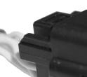
14 8. Connectors 8.1 Firewall Circular Connector The CPC connector is both safe and user friendly and offers the perfect connection solution for the harness through the firewall, by having keys that doesn t allow connection in the wrong position. Sensor Sensor pin/wire Harness wire Cherry GS MSD 8276 MSD 8154 Electrimotion A B C Purple Green Red Black 12V White wire from Crack Hall Battery s negative Red wire from Crank VR Black wire from Crank VR Red wire from Crank VR Black wire from Crank VR 1 Black wire from Crank VR 2 Red wire from Crank VR Cam Sync sensor The PRO600 is made to read the MSD 2346 Cam Sync kit and Cherry GS With MSD 2346, the purple wire must go to the white wire from Cam VR and the green wire must go to the black wire from Cam VR. If for any reason the sensor is not wired like this, swap the wires to match and connect like above. 8.2 Relay and Fuses All relays available in the PRO600 Harness are automotive sealed heavy duty type. The relay max current is 40A followed by a 40A fuse. There is a main relay for the FuelTech units such as ECU, O2 conditioner and sensors. The other relay is for the fuel injectors. Sensor Sensor pin/wire Harness wire Cherry GS MSD 2346 Pro Mag 44 Electrimotion A B C Purple Green Black/Orange Black/Purple 12V White wire from Crack Hall Battery s negative Red wire from Cam VR Black wire from Crank VR Red wire from Cam VR Black wire from Crank VR 1 Black wire from Crank VR 2 Red wire from Cam VR 8.4 TPS 8.3 Crank Trigger and Cam Sync sensor The harness is ready to run MSD 8276 and Cherry GS sensor for the crank trigger. For the cam sync sensor, it is designed to read the MSD 2346 cam sync kit and a hall effect sensor. TPS is a potentiometer that informs the throttle position. FT600 can read almost any 0-5V TPS. The PRO600 harness uses a 3-way male Weather Pack connector. - Pin A: signal ground; - Pin B: 5V supply; - Pin C: signal output. Crank Trigger When using MSD 8276 as crank trigger, be sure that the violet wire from the sensor goes to the red wire of Crank VR connector and the green wire from the sensor goes to the black wire of Crank VR connector. If for any reason the sensor is not wired liked this, swap the wires to match and connect like the above. The Crank VR connector is a MSD 8824 and Crank Hall is a 3-way Metri-Pack
.")


15 8.5 H2O and Air Temperature The PRO600 Harness has 2 temperature inputs. One input is for the engine temperature (H2O) and the other is for the intake air temperature (AIR). Both sensors are GM style and uses Metri-Pack connectors. - Pin A: signal output; - Pin B: battery s negative. 8.8 Injectors There are 8 injector outputs available (primary bank). All injector connectors are Bosch EV1 style. 8.9 Back Pressure H2O 8.6 Oil, Fuel and Wastegate Pressure The oil, fuel and Wastegate pressure sensor connectors are designed for the PS-150, PS-300 and PS-1500 sensors; ranging from 150 to 1500 psi, with a Packard style 3-way connector. It has a 5V ground and signal. - Pin A: battery s negative (black); - Pin B: 5V supply (green/red); - Pin C: signal output (white). Air This is a generic input pressure normally used to read back pressure. It can also be used as a MAP sensor input or any other 0-5V sensor. PRO600 harness comes with a Delphi MetriPack 150 connector and uses the white input #2, which is also available at Extra connector. When the back pressure connector is being used, the white #2 in the Extra connector can t be used. - Pin A: battery s negative (black); - Pin B: 5V supply (green/red); - Pin C: signal output (white). 8.7 Points The points wire is the ignition output when using a distributor based capacitive ignition (like MSD 6/7/8 or Pro Mag 44). The points output is connected to the points input of the ignition box (white wire of MSD 6/7/8 or purple wire of Pro Mag 44). When using a MSD Grid, the FT600 points output must be connected to the points input on the MSD Grid..NOTE: Do not connect the pressure sensor directly to the exhaust manifold. Use a pipe between the sensor and the heat source to prevent overheat Extra Connections Inputs: The inputs connector can be used to read any 0 to 5V analog sensor and it has a 5V output for sensors (green with red stripe) and a 12V output from Relay. Outputs: The output connectors can be used for almost any kind of purpose, activating solenoids (some need relays), loads or be connected to Coil harness and Secondary Injector Harness (sold separately) These connectors have signal outputs (blue, gray and yellow), ground and 12v from relay wires. 15
16 White - Inputs INPUTS - White Pin FT600 Extra White Input Function/Sensor A White input #1 B White input #3 C White input #8 D White input #9 E White input #12 F White input #13 G White Input #14 H White Input #15 J White input #16 K White input #17 L White input #18 M White input #19 N White input #20 P Green/Red 5V outputs for sensors R Red - 12V input from relay S Green/Black - Ground for Sensors Blue - Outputs Pin OUTPUTS A - Blue FT600 Extra Blue Outputs A Blue output #9 B Blue output #10 C Blue output #11 D Blue output #12 E Blue output #13 F Blue output #14 G Blue output #15 H Blue output #16 J Red - 12V input from relay K Black - negative battery L NOT USED M NOT USED Function/Sensor Yellow - Outputs Pin OUTPUTS C - Yellow FT600 Extra Yellow Outputs A Yellow output #1 B Yellow output #2 C Yellow output #3 D Yellow output #4 E Yellow output #5 F Yellow output #6 G Yellow output #7 H Yellow output #8 Function/Sensor Grey - Outputs OUTPUTS B - Grey Pin FT600 Extra Gray Outputs Function/Sensor A Gray output #1 B Gray output #2 C Gray output #3 D Gray output #4 E Gray output #5 F Gray output #6 G Gray output #7 H Gray output #8 J Red - 12V input from relay K Black - negative battery 16

 It can be purchased online at www.fueltech.net or from an authorized FuelTech dealer (check the website to locate the dealer nearest to you).")

.")
 like the following schematic to avoid this issue.")
17 If the system being activated requires a 12v output, the yellow outputs are capable of ground or 12v. If no yellow outputs are available, it s possible to drive a relay by ground with any gray output to get the proper 12v output switched by one of the gray outputs by following this diagram: 9. Standard Sensors 9.1 Fuel and Oil Pressure FuelTech PS-150/300/1500 is a high precision sensor responsible for general pressure readings (fuel, oil, boost, exhaust back pressure, etc.) It can be purchased online at or from an authorized FuelTech dealer (check the website to locate the dealer nearest to you). FuelTech PS-150/300/1500 sensor below: Yellow outputs are the most specialized outputs. They are HALF BRIDGE or PUSH PULL type outputs. This means that they can feed 5A both by negative or positive side. They are important and necessary to control Electronic drive-by-wire throttle (DC motors) and stepper motor 4 wire idle control valves. They also can be used to control any type of LO SIDE or HI SIDE actuator (LO SIDE means the ECU will switch ground to activate the device, HI SIDE means the ECU will switch 12V to active the device). Since it can feed 12V power at 5A, if wired to a relay activating it by ground (from the FuelTech) when turned off, it senses the 12V through the relay coil and feeds back power to the ECU. In this case, it is necessary to run a series diode (4004 or 4007) like the following schematic to avoid this issue. Both ways of wiring this output are described in the following diagrams: - Connection: 1/8-27NPT - Pressure Range: 0 to 150/300/1500psi - Power Voltage: 5V - Output Scale: V - Electric Connector: 3-way Metri Pack Pin 1: Battery s Negative - Pin 2: 5V supply - Pin 3: Output signal FuelTech part numbers: psi sensor psi sensor psi sensor 9.2 Intake Air Temperature With this sensor, the ECU can monitor the intake air temperature and perform real time compensations. One of its pins is connected to the battery negative, the other to the white #7 wire. Part numbers: FuelTech or GM Engine Temperature This sensor is very important for a good running engine, as varying engine temperatures dramatically affect an engine s fuel and timing requirements. On water cooled engines, place this sensor near the engine head, reading the water temperature. On air cooled engines, install this sensor reading the engine oil temperature. One of its pins is connected to the battery negative, the other to the white #5 wire. Part numbers: FuelTech or GM There are some relays with a built-in diode, like Hella


.")


18 10. Meters and adapter wires 10.1 Fuel Tech WB-O2 Nano The WB-02 Nano has a 12-way connector with 3 wire groups. One of them has the connector for the O2 sensor, the second makes the CAN communication with FT600 and the third is responsible for power and analog output NTK WB-O2 sensor - Alcohol The NTK wideband O2 sensor is designed for high accuracy and low AFR s, must be used with FuelTech Alcohol O2. This sensor requires an adapter harness and free-air calibration. For further information, check the FuelTech Alcohol O2 manual. By default, the analog output is set to values of 8.7AFR to 16.2AFR Gas, but can be confi gured to 5.14AFR to 17.6AFR Gas or 9.55 to 19.11AFR or 9.55 to 58.80AFR or yet 9.55 to 146.9AFR (Gas), if necessary. For further information, check the FuelTech WB-O2 Nano manual Bosch LSU 4.2 O2 sensor to Alcohol O2 adapter harness 10.2 Alcohol O2 The FuelTech Alcohol O2 is a dual channel O2 reader and is designed to read extremely low AFRs, recommended mainly for alcohol engines in drag race application, since it is able to read down to 0.28 lambda (1.79AFR alcohol, 2.52AFR E100 or 4.12AFR gasoline). FuelTech Alcohol O2 has an AMP Super Seal connector. For further information, check the FuelTech Alcohol O2 manual. This adapter is required when using the Alcohol O2 with Bosch LSU 4.2 O2 sensors. Each channel of the Alcohol O2 can read a single Bosch LSU 4.2 O2 sensor. To purchase the adapter harness, contact FuelTech. Part numbers: FuelTech or Bosch WB-O2 sensor Bosch to NTK adapter harness This adapter is necessary to use 16 injectors with Alcohol O2. To purchase the adapter harness, contact FuelTech Bosch LSU 4.2 Wideband O2 Sensor The BOSCH LSU 4.2 is a wideband O2 sensor that can be used with both the WB-O2 Nano and Alcohol O2. When using LSU 4.2 with our Alcohol O2 reader, an adapter harness is required, as well as free air calibration. Check the Alcohol O2 manual for further instructions. 18

19 11. Peak and Hold - External Injector Driver Peak and Hold drivers are designed to control the current on low impedance injectors. The FuelTech Peak and Hold has 4 outputs and in the PRO Wiring Harness will run one injector per channel. There are 3 different versions of Peak and Hold available to fire different injectors, according to the resistance of the injector. The only differences between the versions are the peak current and the hold current. Some earlier Moran injectors require a 4A/1A driver. Contact FuelTech tech support to confirm correct Peak and Hold drivers before purchasing. When using high impedance injectors without Peak and Hold drivers, jumpers wires (sold separately, part number ) must be connected to the Peak and Hold plugs in the harness. If the jumper wires are not being used then the injectors won t fire since there will be no continuity between the FT600 and injectors. Considering one injector per channel application: 2A/0.5A Bosch 1600cc, Ford Racing 1600cc 4A/1A Siemens Deka 225lb/hr, Precision 225lb/hr 8A/2A Precision 550lb/hr, Billet Atomizer, Moran 12. Troubleshooting Issue FT600 Unit doesn t turn on FT600 doesn t read cranking FT600 reads RPM but engine doesn t start Engine runs but doesn t idle Engine spits & sputters ECU won t communicate to PC Solution 1. Check battery voltage 2. Check power and ground cables 3. Check Switched 12V cable 4. Check ECU harness cables 1. Check crank trigger and cam sync connections (chapter 7.3) 2. Check sensor gap 3. Check diagnostic panel for RPM signal 1. Check if there is spark and injector pulse 2. Check fuel pressure 3. Check crank trigger alignment and TPS calibration 4. Check if outputs are activated and properly configured 5. Check the O2 sensor reading 1. Check TPS calibration 2. Check timing with a timing light 3. Check TPS idle table and adjustment 4. Check O2 sensor reading 1. Check O2 sensor reading 2. Check ignition calibration and firing order 1. Ensure your software version is compatible with your FT600 firmware version 2. Check if read and write buttons get colored when FT600 is connected 13. FuelTech Latest Manuals and Software You can access all updated manuals and software at the FuelTech website:
20
21

22 455 Wilbanks Dr. Ball Ground, GA, 30107, USA Phone: Toll Free: FuelTechUSA POWER FT ECU
1. Index. LS Wiring Harness. 2. Presentation Warnings and Warranty Terms Overview Labels...7
 OWNER S MANUAL 1. Index 2. Presentation...4 3. Warnings and Warranty Terms...5 4. Overview...6 5. Labels...7 6. Diagrams...7 6.1 FT500/FT500 Aux - Inputs/outputs...7 6.2 Nano WB O2 #1...8 6.3 Nano WB
MaxxECU quickstart guide ( )
") Be a tuning mastermind. Like us. MaxxECU quickstart guide (2019-02-01) Online help! maxxecu.com/support Wiring diagrams Installation help Pinout Support maxxecu.com/support Legal disclaimer All performance
Be a tuning mastermind. Like us. MaxxECU quickstart guide (2019-02-01) Online help! maxxecu.com/support Wiring diagrams Installation help Pinout Support maxxecu.com/support Legal disclaimer All performance
6 channel Datalogger with WB-O2 buit-in signal conditioner Installation and Operation Guide
 6 channel Datalogger with WB-O2 buit-in signal conditioner Installation and Operation Guide Summary 1 Presentation... 4 2 Warnings and Warranty Terms... 5 3 WB-O2 Datalogger Electric Installation... 6
Manual de Instalação e Operação Installation and Operation Guide Manual de Instalación y Especificaciones Técnicas
 capa Condicionador para Sensor Lambda Banda Larga Wideband Lambda Sensor Conditioner Condicionador para Sensor Lambda de Banda Ancha Manual de Instalação e Operação Installation and Operation Guide Manual
ELITE 1000/1500 Dodge SRT QUICK START GUIDE HT
 E N G I N E M A N A G E M E N T S Y S T E M S ELITE 1000/1500 Dodge SRT4 03-05 QUICK START GUIDE HT-140940 LIMITED WARRANTY Lockin Pty Ltd trading as Haltech warrants the HaltechTM Programmable Fuel Injection
Manual - FTSPARK v3 - Capas ENUS.pdf 1 2/16/2017 6:06:34 PM C M Y CM MY CY CMY K OWNER S MANUAL
 OWNER S MANUAL Index 1. Presentation...4 2. Characteristics...5 3. Warranty terms...6 4. Installation...7 4.1 Mounting...7 4.2 Power supply...7 4.3 Harness connections table...8 4.4 Wiring harness installation...
EFI HARNESS KIT , & Kit Contents: Power Harness : All Kits
 EFI HARNESS KIT 558-500, 558-501 & 558-502 Kit Contents: Main Harness 558-102: Kits 558-500 558-103: Kits 558-501 & 502 Power Harness 558-308: All Kits Injector Harness 558-200: Kits 558-500 & 502 558-201:
Ford EV6 Injector Adapter Harness User Manual
 Ford EV6 Injector Adapter Harness User Manual 30-3805- THIS PRODUCT IS LEGAL IN CALIFORNIA FOR RACING VEHICLES ONLY AND SHOULD NEVER BE USED ON PUBLIC HIGHWAYS. AEM Performance Electronics AEM Performance
Speed-Pro EFI Installation Manual
 Speed-Pro EFI Installation Manual Speed-Pro Electronics Installation Manual Page The wiring harness is labeled on each of the connectors to simplify installation. Your application may not require the use
ECUS PERFORMANCE IN YOUR HANDS! SUMMARY CONTROLLERS METERS AND LOGGERS IGNITION SENSORS AND ACCESSORIES FT APPAREL
 207 PERFORMANCE IN YOUR HANDS! FuelTech is an international company specialized in developing and manufacturing state of the art performance engine management systems. The company s elite staff, always
GM Stepper Idle Adapter User Manual
 GM Stepper Idle Adapter User Manual 30-3805-07 THIS PRODUCT IS LEGAL IN CALIFORNIA FOR RACING VEHICLES ONLY AND SHOULD NEVER BE USED ON PUBLIC HIGHWAYS. AEM Performance Electronics AEM Performance Electronics,
Core Harness System Crank/Cam Adapter Harness FAST Dual Sync Distrubutor 35" STOP!
 Instruction Manual 30-3805-20 Core Harness System Crank/Cam Adapter Harness FAST Dual Sync Distrubutor 35" STOP! THIS PRODUCT HAS LEGAL RESTRICTIONS. READ THIS BEFORE INSTALLING/USING! THIS PRODUCT MAY
PLATINUM Sport Haltech GM LS1 / LS6 Terminated Engine Harness (HT045650) QUICK START GUIDE
 QUICK START GUIDE") PLATINUM Sport 2000 Haltech GM LS1 / LS6 Terminated Engine Harness (HT045650) QUICK START GUIDE LIMITED WARRANTY Lockin Pty Ltd trading as Haltech warrants the Haltech TM Programmable Fuel Injection System
PLATINUM Sport 2000 Haltech GM LS1 / LS6 Terminated Engine Harness (HT045650) QUICK START GUIDE LIMITED WARRANTY Lockin Pty Ltd trading as Haltech warrants the Haltech TM Programmable Fuel Injection System
MegaSquirt III for LS Style Engines. Hardware Install. 1. Disconnect and remove the battery from the vehicle.
 MegaSquirt III for LS Style Engines MegaSquirt controllers are experimental devices intended for educational purposes. MegaSquirt controllers are not for sale or use on pollution controlled vehicles. Check
Quick Start Guide. This is only a quick start guide. A full wiring and installation manual is included in PCLink.
 Quick Start Guide This is only a quick start guide. A full wiring and installation manual is included in PCLink. Installer I/O Table Wire Description Installer Connection Typical Application +14V Bat Full
GM Throttle Body Adapter Harness User Manual
 GM Throttle Body Adapter Harness User Manual 30-3809-01 THIS PRODUCT IS LEGAL IN CALIFORNIA FOR RACING VEHICLES ONLY AND SHOULD NEVER BE USED ON PUBLIC HIGHWAYS. AEM Performance Electronics AEM Performance
MegaSquirt III for Gen 3 HEMI. Hardware Install THE FOLLOWING SENSOR PART NUMBERS APPLY TO ALL HARNESSES FOR ENGINES 2004 TO CURRENT:
 MegaSquirt III for Gen 3 HEMI MegaSquirt controllers are experimental devices intended for educational purposes. MegaSquirt controllers are not for sale or use on pollution controlled vehicles. Check the
Syvecs S6 GP. Syvecs Limited. Pinouts and Wiring Info. Ryan Griffiths
 1 Syvecs Limited Syvecs S6 GP Pinouts and Wiring Info Ryan Griffiths 24 10 2011 This document intended for use by a technical audience and describes a number of procedures that are potentially hazardous.
Engine Management and Data Acquisition Systems
 Engine Management and Data Acquisition Systems In 2013 FuelTech celebrates ten years of innovative success and, although young, it has become a synonym of quality high performance. The company was created
INSTALLATION INSTRUCTIONS. Revision 4.0.3
 INSTALLATION INSTRUCTIONS Revision 4.0.3 Table of Contents INTRODUCTION... 3 INSTALLATION OVERVIEW... 4 Included Parts... 5 DEVICE WIRING... 6 Required Parts... 6 Guidelines... 6 Wiring Diagram... 7 Engine
HP and Dominator Component Selection Guide. Use when building Dominator Systems or Custom HP Systems. Step 2 (notes) Choose Your Main Harness
 Choose Your Main Harness") HP and Dominator Component Selection Guide Use when building Dominator Systems or Custom HP Systems Step 1 (required) Choose your ECU & Main Power Harness Step 2 (notes) Choose Your Main Harness Step 3
HP and Dominator Component Selection Guide Use when building Dominator Systems or Custom HP Systems Step 1 (required) Choose your ECU & Main Power Harness Step 2 (notes) Choose Your Main Harness Step 3
INSTALLATION INSTRUCTIONS. Revision 3.1.1
 INSTALLATION INSTRUCTIONS Revision 3.1.1 Table of Contents INTRODUCTION... 4 INSTALLATION OVERVIEW... 5 Included Parts... 6 DEVICE WIRING... 7 Required Parts... 7 Guidelines... 7 Wiring Diagram... 8 Compatible
Crank Trigger Hardware Installation
 Crank Trigger Hardware Installation Step 1 - Bring the engine up to TDC and remove the crank pulley bolt. Step 2 - Install trigger wheel making sure to line up the keyway. You may need to use the bolt
Installation Instructions for: EMS P/N Ford Mustang 5.0L
 Installation Instructions for: EMS P/N 30-1400 1986-93 Ford Mustang 5.0L! WARNING: This installation is not for the tuning novice nor the PC illiterate! Use this system with EXTREME caution! The AEM EMS
FAST XIM. XIM Unit Installation
 1 INSTRUCTIONS XIM Thank you for choosing products; we are proud to be your manufacturer of choice. Please read this instruction sheet carefully before beginning installation, and also take a moment to
MSD 7AL-3, Ignition Control PN 7230
 MSD 7AL-3, Ignition Control PN 7230 Important: Read the instructions before attempting the installation. Parts Included: 1-7AL-3, PN 7230 1 - Parts bag (wires and connectors) 4 - RPM Modules 3000, 7000,
LSx Harness Installation. lsxeverything.com #BecauseYouShould
 LSx Harness Installation lsxeverything.com #BecauseYouShould Table of Contents Slide 1 Introduction Page Slide 2 Table of Contents Slide 3 Starting Instructions Slide 4 Power Connections Slide 5 Ground
PLATINUM. Sport Haltech 13B Terminated Engine Harness QUICK START GUIDE
 PLATINUM Sport 1000 Haltech 13B Terminated Engine Harness QUICK START GUIDE HALTECH HEAD OFFICE: PH: +612 9729 0999 FAX: +612 9729 0900 EMAIL: sales@haltech.com HALTECH US OFFICE: EMAIL: usa@haltech.com
Installation Instructions for: EMS P/N Ford Mustang 5.0L
 Installation Instructions for: EMS P/N 30-1401 1994-95 Ford Mustang 5.0L! WARNING: This installation is not for the tuning novice nor the PC illiterate! Use this system with EXTREME caution! The AEM EMS
Gen III HEMI Harness PN or
 Gen III HEMI Harness PN 558-106 or 558-107 This wiring harness interfaces a Holley EFI ECU to a Gen III HEMI engine. It is meant to be used in conjunction with an injector harness, a coil harness, and
Installation Instructions for: EMS P/N and U Honda S2000
 Installation Instructions for: EMS P/N 30-1052 and 30-1052U 00-04 Honda S2000! WARNING: This installation is not for the tuning novice nor the PC illiterate! Use this system with EXTREME caution! The AEM
MSD 6LS-2 Ignition Controller for Carbureted and EFI LS 2/LS 7 Engines PN 6012
 MSD 6LS-2 Ignition Controller for Carbureted and EFI LS 2/LS 7 Engines PN 6012 ONLINE PRODUCT REGISTRATION: Register your MSD product online. Registering your product will help if there is ever a warranty
MSD Boost Control Module PN 7763
 MSD Boost Control Module PN 7763 ONLINE PRODUCT REGISTRATION: Register your MSD product online. Registering your product will help if there is ever a warranty issue with your product and helps the MSD
MSD 6-Mod Controller for Carbureted and EFI Gen III Engines PN 6011
 MSD 6-Mod Controller for Carbureted and EFI Gen III Engines PN 6011 ONLINE PRODUCT REGISTRATION: Register your MSD product online. Registering your product will help if there is ever a warranty issue with
Timing Input Adapter User Manual
 Timing Input Adapter User Manual 30-3805-05 2 AEM Infinity Harness Manuals Introduction Several universal wiring harness options are available for Infinity products. They range in complexity from simple
Controller Ground (dual black 12awg) should be connected to chassis ground as close as possible to the battery.
 should be connected to chassis ground as close as possible to the battery.") 1. Overview The Maximizer 4 progressive nitrous controller operates one or two separate stages of nitrous based on either time, RPM, MPH, throttle percentage or boost pressure. Whether your engine is naturally
1. Overview The Maximizer 4 progressive nitrous controller operates one or two separate stages of nitrous based on either time, RPM, MPH, throttle percentage or boost pressure. Whether your engine is naturally
MSD Boost Control Module PN 77631
 MSD Boost Control Module PN 77631 ONLINE PRODUCT REGISTRATION: Register your MSD product online. Registering your product will help if there is ever a warranty issue with your product and helps the MSD
Products Kronenburg Management Systems. kms.vankronenburg.nl
 Products 2011 Kronenburg Management Systems kms.vankronenburg.nl Kronenburg Management Systems (KMS) is a complete line of engine management systems that offers you an extremely reliable and user-friendly
Installation Instructions for: EMS P/N Acura Integra Acura 2.3CL Honda Accord Honda Civic
 ! Installation Instructions for: EMS P/N 30-1010 00-01 Acura Integra 98-99 Acura 2.3CL 98-02 Honda Accord 99-00 Honda Civic WARNING: This installation is not for the tuning novice nor the PC illiterate!
GM EV6 Injector Adapter Harness User Manual
 GM EV6 Injector Adapter Harness User Manual 30-3805-0 THIS PRODUCT IS LEGAL IN CALIFORNIA FOR RACING VEHICLES ONLY AND SHOULD NEVER BE USED ON PUBLIC HIGHWAYS. Introduction Some harness user manuals contain
SCHNITZ MOTORSPORTS USER MANUAL AND INSTALLATION GUIDE PRO-MOD BATTERY VOLTS DIAGNOSTICS NOS PULSE FREQUENCY NOS DELAY TIME IN SECONDS
 SCHNITZ MOTORSPORTS DSC-CS "PRO-MOD" IGNITION CONTROLLER USER MANUAL AND INSTALLATION GUIDE COIL, (OPTIONAL) GA YELLOW, COIL, NEGATIVE GA WHITE, GA BLACK, SHIFT LIGHT +V OUTPUT PAGE 0 NOS ACTIVATION INPUT
1CH Ignition Adapter Harness User Manual
 CH Ignition Adapter Harness User Manual 30-3805-02 2 AEM Infinity Harness Manuals Introduction Several universal wiring harness options are available for Infinity products. They range in complexity from
Ford Coyote Main Harness and Harness Kit PN , , and
 Ford Coyote Main Harness and Harness Kit PN 558-110, 550-619, and 550-625 This wiring harness interfaces a Holley EFI ECU to a Ford Coyote engine that has either had the cam VVT hardware locked out or
Installation Instructions for: EMS P/N Eclipse Turbo, Talon Tsi, Laser RS Galant VR4
 Installation Instructions for: EMS P/N 30-6300 1990-1994 Eclipse Turbo, Talon Tsi, Laser RS Galant VR4 Thank you for purchasing an AEM Engine Management System. The AEM Engine Management System (EMS) is
MSD LS-1/LS-6 Controller for Carbureted and EFI Gen III Engines PN 6010
 MSD LS-1/LS-6 Controller for Carbureted and EFI Gen III Engines PN 6010 Parts Included 1 Ignition Controller, PN 6010 1 Pro-Data+ Software CD 1 Harness 1 Parts Bag 6 Timing Modules Optional Accessories
MSD Stacker-4 (4-Channel), PN 7010 Stacker-8 (8-Channel), PN 7020
, PN 7010 Stacker-8 (8-Channel), PN 7020") INSTALLATION INSTRUCTIONS 1 MSD Stacker-4 (4-Channel), PN 7010 Stacker-8 (8-Channel), PN 7020 Important: Read these instructions before attempting this installation! Parts Included: 1 - MSD Stacker Ignition
INSTALLATION INSTRUCTIONS 1 MSD Stacker-4 (4-Channel), PN 7010 Stacker-8 (8-Channel), PN 7020 Important: Read these instructions before attempting this installation! Parts Included: 1 - MSD Stacker Ignition
GM Injector Adapter Harness User Manual
 GM Injector dapter Harness User Manual 30 3805 00 2 EM Infinity Harness Manuals Introduction Several universal wiring harness options are available for Infinity products. They range in complexity from
Quick Start Guide. This is only a quick start guide. A full wiring and installation manual is included in PCLink.
 Quick Start Guide This is only a quick start guide. A full wiring and installation manual is included in PCLink. Installer I/O Table Wire Description Installer Connection Typical Application Trigger 1
Installation Instructions for: EMS P/N Toyota MR2 Turbo Toyota Celica All Trac
 Installation Instructions for: EMS P/N 30-1120 1991-1992 Toyota MR2 Turbo 1990-1992 Toyota Celica All Trac! WARNING: This installation is not for the tuning novice nor the PC illiterate! Use this system
DYNOTUNE 2 STAGE RPM WINDOW SWITCH WITH TPS INSTALLATION INSTRUCTIONS
 DYNOTUNE 2 STAGE RPM WINDOW SWITCH WITH TPS INSTALLATION INSTRUCTIONS Introduction: READ ALL INSTRUCTIONS BEFORE STARTING! This DynoTune device will control up to two stages of nitrous oxide. They are
MALLORY FIRESTORM CD MULTI COIL HARDWARE INSTALLATION - PN 69150C / 69150R
 FORM 69150C/R MALLORY FIRESTORM CD MULTI COIL HARDWARE INSTALLATION - PN 69150C / 69150R To ensure you are using the most current instruction sheet, please visit www.malloryfirestorm.com. CAUTION! The
MSD 6-Mod Controller for Carbureted and EFI Gen III Engines PN 6011
 MSD 6-Mod Controller for Carbureted and EFI Gen III Engines PN 6011 Parts Included 1 - Ignition Controller, PN 6011 1 - Pro-Data+ Software CD 1 - Harness 1 - Parts Bag 1-2-Bar MAP Sensor Optional Accessories
This product is legal in California for racing vehicles only and should never be used on public highways.
 Installation Instructions for: EMS P/N 30-1602 and 30-1602U 96-99 Nissan 180SX SR20DET 97-98 Nissan Silvia S14 SR20DET 93-98 Nissan Silvia S14 SR20DET (Europe) 99-02 Nissan Silvia S15 SR20DET! WARNING:
10 Ch Peak & Hold Injector Driver PN
 Installation Instructions 10 Ch Peak & Hold Injector Driver PN 30-2710 WARNING: installation is not for the electrically challenged! Use this product with extreme caution! If you are uncomfortable with
Ford Coyote Non-VVT Main Harness PN
 Ford Coyote Non-VVT Main Harness PN 558-114 This wiring harness interfaces a Holley EFI ECU to a Ford Coyote engine that has had the cam VVT hardware locked out. It is meant to be used in conjunction with
WIRING MANUAL & DIAGRAMS 199R10555
 WIRING MANUAL & DIAGRAMS 199R10555 HP EFI and Dominator EFI Systems Contents 1.0 Manual Overview... 2 1 1.1 Important Wiring Do s and Don ts... 3 2.0 ECU Installation, Connectors, and Pinout... 3 2.1 Pinout...
DUAL WIDEBAND AIR/FUEL RATIO GAUGE Product Numbers: GS-W702W_Dual, GS-C702W_Dual, GS-T702W_Dual
 Installation Instructions Tech Support: 856.768.8300 TechSupport@GlowShiftGauges.com DUAL WIDEBAND AIR/FUEL RATIO GAUGE Product Numbers: GS-W702W_Dual, GS-C702W_Dual, GS-T702W_Dual (1) Gauge (2) Controllers
DFS-1000 Wiring Diagrams and PC Software Installation.
 DFS-1000 Wiring Diagrams and PC Software Installation. For Technical Support Please contact your dealer or email seellc@mchsi.com 1 Important Information - When using a conventional style ignition coil
Installation Instructions for: EMS P/N Silvia S13 SR20DET Nissan 180SX SR20DET
 Installation Instructions for: EMS P/N 30-6601 1991-1993 Silvia S13 SR20DET 1991-1995 Nissan 180SX SR20DET! WARNING: This installation is not for the tuning novice nor the PC illiterate! Use this system
Quick Start Guide. This is only a quick start guide. A full wiring and installation manual is included in PCLink.
 Quick Start Guide This is only a quick start guide. A full wiring and installation manual is included in PCLink. Installer I/O Table Wire Description Installer Connection Typical Application Trigger 1
MALLORY FIRESTORM CD MULTI COIL HARDWARE INSTALLATION - PN 69050S / 69050R
 FORM 69050S/R MALLORY FIRESTORM CD MULTI COIL HARDWARE INSTALLATION - PN 69050S / 69050R To ensure you are using the most current instruction sheet, please visit www.malloryfirestorm.com. CAUTION! The
MSD-8 Plus Ignition PN 7805
 MSD-8 Plus Ignition PN 7805 Note: Solid Core spark plug wires cannot be used with an MSD Ignition. Parts Included: 1 - MSD-8 Plus Ignition 1 - Mag Pickup Extension Harness, PN 8860 4 - Vibration Mounts
Chevy Truck
 Classic Instruments 1973 1987 Chevy Truck Installation Manual Table of Contents Welcome from the Team at Classic Instruments!... 3 Gauge Mounting... 4 Gauge Cluster Wiring... 6 Pulse Signal Generator [SN16]
Part Number AEM 4-CH WIDEBAND UEGO CONTROLLER
 Part Number 30-2340 AEM 4-CH WIDEBAND UEGO CONTROLLER FIGURE 1. WIRING DIAGRAM AEM Performance Electronics 2205 126 th Street Unit A, Hawthorne, CA. 90250 Phone: (310) 484-2322 Fax: (310) 484-0152 http://www.aemelectronics.com
Megasquirt EX, Installation Instructions document revision 1.4 (Includes also the version equipped with wasted-spark ignition)
") Megasquirt EX, Installation Instructions document revision 1.4 (Includes also the version equipped with wasted-spark ignition) General Megasquirt EX is a programmable engine control system, based on Megasquirt
Megasquirt EX, Installation Instructions document revision 1.4 (Includes also the version equipped with wasted-spark ignition) General Megasquirt EX is a programmable engine control system, based on Megasquirt
Installation Instructions for: EMS P/N Eclipse Turbo, Talon Tsi, Laser RS Galant VR4
 Installation Instructions for: EMS P/N 30-6300 1990-1994 Eclipse Turbo, Talon Tsi, Laser RS Galant VR4! WARNING: This installation is not for the tuning novice nor the PC illiterate! Use this system with
AEROMOTIVE Part # INSTALLATION INSTRUCTIONS
 AEROMOTIVE Part # 16306 INSTALLATION INSTRUCTIONS CAUTION: Installation of this product requires detailed knowledge of automotive systems and repair procedures. We recommend that this installation be carried
PLUG & PLAY. Quick Start Guide. GM LS 58X Drop On Harness. MS3Pro ULTIMATE
 Quick Start Guide PLUG & PLAY GM LS 58X Drop On Harness MS3Pro ULTIMATE For GM LS Engines with 58X Crank Triggers Thank you for your purchase and support for American made products! We have designed this
SimMotor User Manual Small Engine Simulator and HIL V COPY RIGHTS ECOTRONS LLC All rights reserved
 V2.3.1 SimMotor User Manual Small Engine Simulator and HIL V2.3.1 COPY RIGHTS ECOTRONS LLC All rights reserved Http://www.ecotrons.com Table of Contents Read before you start:...1 Why do I need SimMotor?...2
Montero Sport L ECM/ L A/T PCM Pin-Out Table for Piggy-Back AEM F/IC 8 & Innovate LC-1 WBO M/T ECM & 1999 A/T PCM
 Montero Sport 199 3.0L ECM/1999 3.5L A/T PCM Pin-Out Table for Piggy-Back AEM F/IC 8 & Innovate LC-1 WBO2 Pin-outs were taken directly from the official Mitsubishi factory service manuals and as such may
MSD Single Cylinder Programmable Ignition PN 4217
 MSD Single Cylinder Programmable Ignition PN 4217 Parts Included: 1 - PN 4217 1 - PN 4217 Wire Harness 1 - CD Rom 9609 1 - Parts Bag 1 - Serial Cable WARNING: During installation, disconnect the battery
Classic Instruments Camaro. Installation Manual. Revised: January 6, 2015 Page 1
 Classic Instruments 1967 1968 Camaro Installation Manual Revised: January 6, 2015 Page 1 Contents Welcome from the Team at Classic Instruments!... 3 Remove Original Instrument Panel... 4 New Instrument
* NOTE: Legal in California only for racing vehicles which may never be used upon a highway
 Read and understand these instructions BEFORE attempting to install this product. Failure to follow installation instructions and not using the provided hardware may damage the intake tube, throttle body
Installation Instructions for: EMS P/N Toyota Supra
 Installation Instructions for: EMS P/N 30-1110 1987-1988 Toyota Supra! WARNING: This installation is not for the tuning novice nor the PC illiterate! Use this system with EXTREME caution! The AEM EMS System
PLATINUM Series CAN WIDEBAND CONTROLLER WBC 1 & WBC 2 QUICK START GUIDE (HT & HT059980) Version 4
 Version 4") PLATINUM Series CAN WIDEBAND CONTROLLER WBC 1 & WBC 2 (HT059970 & HT059980) QUICK START GUIDE HALTECH HEAD OFFICE: PH: +612 9729 0999 FAX: +612 9729 0900 EMAIL: sales@haltech.com HALTECH US OFFICE: PH:
PLATINUM Series CAN WIDEBAND CONTROLLER WBC 1 & WBC 2 (HT059970 & HT059980) QUICK START GUIDE HALTECH HEAD OFFICE: PH: +612 9729 0999 FAX: +612 9729 0900 EMAIL: sales@haltech.com HALTECH US OFFICE: PH:
Classic Instruments & 1956 Chevy. Installation Manual
 Classic Instruments 1955 & 1956 Chevy Installation Manual Table of Contents Welcome from the Team at Classic Instruments!... 3 Disassemble Original Gauge... 4 Assemble New Gauge Cluster... 5 Speedo, Tach,
Classic Instruments Chevelle. Installation Manual
 Classic Instruments 1964 1965 Chevelle Installation Manual Table of Contents Welcome from the Team at Classic Instruments!... 3 Included Mounting Hardware... 4 Mounting Gauges... 5 Wiring Diagram... 6
2 Wire PW Idle Adapter User Manual
 2 Wire PW Idle Adapter User Manual 30-3805-08 2 AEM Infinity Harness Manuals Introduction Several universal wiring harness options are available for Infinity products. They range in complexity from simple
Installation Instructions for: EMS P/N Toyota Supra
 Installation Instructions for: EMS P/N 30-1130 1989-1992 Toyota Supra! WARNING: This installation is not for the tuning novice nor the PC illiterate! Use this system with EXTREME caution! The AEM EMS System
TELORVEK EFI 5.0 Coyote Sequential Fuel Injection System Part # CY-11
 Page #1 TELORVEK EFI 5.0 Coyote Sequential Fuel Injection System Part # CY-11 WIRING INSTRUCTIONS Thank you for purchasing the absolute finest of wiring kits for the Ford Motor Co. Coyote modular engine.
Installation Instructions for: EMS P/N Acura NSX
 Installation Instructions for: EMS P/N 30-1042 1991-94 Acura NSX! WARNING: This installation is not for the tuning novice nor the PC illiterate! Use this system with EXTREME caution! The AEM EMS System
Installation Instructions for: EMS P/N Mitsubishi 3000GT VR Dodge Stealth TT
 Installation Instructions for: EMS P/N 30-6311 1991-97 Mitsubishi 3000GT VR4 1991-1997 Dodge Stealth TT! WARNING: This installation is not for the tuning novice nor the PC illiterate! Use this system with
MSD Coil Power Booster for Ford 4.6L/5.4L Mod Motors 99-On PN 8740
 MSD Coil Power Booster for Ford 4.6L/5.4L Mod Motors 99-On PN 8740 ONLINE PRODUCT REGISTRATION: Register your MSD product online. Registering your product will help if there is ever a warranty issued with
MSD-8 Plus Ignition PN 7805
 MSD-8 Plus Ignition PN 7805 ONLINE PRODUCT REGISTRATION: Register your MSD product online. Registering your product will help if there is ever a warranty issue with your product and helps the MSD R&D team
MSD Circle Track LS Ignition Control PN 6014CT
 MSD Circle Track LS Ignition Control PN 6014CT ONLINE PRODUCT REGISTRATION: Register your MSD product online. Registering your product will help if there is ever a warranty issue with your product and
MS3-Pro LSx Drop On Harness
 24x MS3-Pro LSx Drop On Harness For engines with 24X crank triggers Thank you for buying our drop on wiring harness! We have designed this harness to support anything from a stock motor swapped into a
Chevy Truck
 Classic Instruments 1954 1955 Chevy Truck Installation Manual Table of Contents Welcome from the Team at Classic Instruments!... 3 Mounting Gauges... 4 4 5/8 Speedometer Wiring [no included tachometer]...
Adaptronic esel020 Select ECU for Nissan S13 240SX (KA24DE) / RNN14 GTiR / SR20VE
 / RNN14 GTiR / SR20VE") 1 P a g e Adaptronic esel020 Select ECU for Nissan S13 240SX (KA24DE) / RNN14 GTiR / SR20VE Applicable vehicles / engines: Nissan S13 KA24DE 240SX US Market Nissan N14 SR20DET / SR20VE - Pulsar GTi-R /
1 P a g e Adaptronic esel020 Select ECU for Nissan S13 240SX (KA24DE) / RNN14 GTiR / SR20VE Applicable vehicles / engines: Nissan S13 KA24DE 240SX US Market Nissan N14 SR20DET / SR20VE - Pulsar GTi-R /
INSTRUCTION MANUAL G-Surge Tank #40007, #40008 & #40009
 FiTech Fuel Injection INSTRUCTION MANUAL Tank #40007, #40008 & #40009 Warning: Caution must be observed when installing any product involving fuel system parts or gas tank modifications. Work in a well
MSD 6-Hemi Controller for Carbureted and EFI Hemi Engines PN 6013
 MSD 6-Hemi Controller for Carbureted and EFI Hemi Engines PN 6013 Parts Included: 1 - Ignition Controller, PN 6013 1 - Pro-Data+ Software CD 1 - Parts Bag 1 - Mounting Template Optional Accessories: Hand
INSTALLATION INSTRUCTIONS 5" SINGLE CHANNEL ULTIMATE TACH
 Instr. No. 2650-887D INSTALLATION INSTRUCTIONS 5" SINGLE CHANNEL ULTIMATE TACH IMPORTANT WEAR SAFETY GLASSES 5 4 6 COPYRIGHT PATENT PENDING 3 7 8 PLAYBACK 9 2 0 1 AUTO METER PRODUCTS, INC. SYCAMORE, IL
CPi. CoiL PACK IGNiTioN FOR AViATiON. For 4,6 and 8 cylinder 4 stroke applications. Please read the entire manual before beginning installation.
 1 CPi CoiL PACK IGNiTioN FOR AViATiON Coil pack (4 cylinder) Coil pack (6 cylinder) For 4,6 and 8 cylinder 4 stroke applications. Please read the entire manual before beginning installation. Software version
TELORVEK II RJ-32 Big Block RamJet Fuel Injection System
 Page #1 TELORVEK II RJ-32 Big Block RamJet Fuel Injection System This wiring system is compatible with the GM Performance part big block Ramjet 502 engine. The harness is designed to dress up the appearance
INFINITY APPLICATION GUIDE
 PLUG & PLAY APPLICATIONS INFINITY SERIES 7 INFINITY PLATFORM** Vehicle Adapter Harness Make Year Model Engine 708 710 712 Part # Adapter Harness BMW 2001 2006 E46 M3 S54 3.2L Inline 6 30 7109 30 7105 N/A
RC Engine-EFI. Installation Manual
 RC Engine-EFI RC Engine Electronic Fuel Injection -- Conversion Kit For 120cc to 300cc engines Installation Manual ECOTRONS V1.2.3 http://www.ecotrons.com/ COPY RIGHTS ECOTRONS LLC ALL RIGHTS RESERVED
Mustang. Installation Manual
 1967-1968 Mustang Installation Manual I Table of Contents TABLE OF CONTENTS... II WELCOME TO THE TEAM OF CLASSIC INSTRUMENTS!... III REMOVE ORIGINAL INSTRUMENT PANEL... 1 DETERMINE SPEEDOMETER SIGNAL...
3-Stage Retard PN 8970
 3-Stage Retard PN 8970 IMPORTANT: Read the instructions before attempting the installation. Parts Included: 1-3-Stage Retard Control 4 - Mounting Screws 4 - Mounting Grommets 6 - Retard Modules, 2, 3,
ISIS Power Manual and Installation Guide Race Car Replicas- Superlite Coupe
 ISIS Power Manual and Installation Guide Race Car Replicas- Superlite Coupe Table of Contents Overview... 2 System Details... 3 Kit Includes... 3 Technical Specifications... 3 Harness Descriptions... 4
Tach-Force Chevy Truck
 Classic Instruments Tach-Force 1955 1959 Chevy Truck Installation Manual Table of Contents Welcome from the Team at Classic Instruments!... 3 Mount New Gauge Cluster... 4 Instrument Cluster Wiring... 5
MODEL: PLJX GM PASSLOCK 1 & 2 & VATS & ION SELF LEARNING DIGITAL INTERFACE: JUMPER SELECTION
 DL doorlock INTERFACE MODEL: PLJX GM PASSLOCK 1 & 2 & VATS & ION SELF LEARNING DIGITAL INTERFACE: JUMPER SELECTION INSTALLATION GUIDE PRODUCT DESCRIPTION PLJX is a "Self Learning" unit designed to bypass