Design of Automotive Aeroacoustic Wind Tunnels
|
|
|
- Baldric Roberts
- 5 years ago
- Views:
Transcription
1 R. Blumrich, J. Wiedemann FKFS, Pfaffenwaldring 12, Stuttgart GERMANY ABSTRACT Wind tunnels comprise a variety of sound sources such as fan, collector, screens, heat exchanger, etc. To enable aeroacoustic measurements, all these sources should be treated by special techniques in order to establish a minimized background noise. In the present paper, these techniques are pointed out. Focal point is given on wind tunnel buffeting, sound absorbing techniques, noise abatement of the fan, the test section, the heat exchanger, turning vanes, and the settling chamber. The new topic turbulence and side wind gust generation is also discussed. 1 INTRODUCTION Reliable acoustic development of vehicles requires the knowledge of the main sound sources. In order to get an optimum test environment, however, some basic rules have to be considered. This means, all of the sound power contributions have to be taken into account, not only the object to be tested but also the self-noise of the test environment. Regarding aeroacoustic wind tunnels this applies specific components of the wind tunnel which are the main sound sources like fan, collector, screens etc.. The key point of the considerations is their impact on the plenum noise. In this respect, first optimisation criteria have to be put forward by lowering the main sound sources, because there is only minor benefit from attenuating secondary acoustic contributions. Besides the aeroacoustic design aspect of the facility itself, an appropriate measurement equipment has to be installed. The interior acoustics e.g. in a vehicle can be covered by common measurement techniques whereas exterior acoustic instrumentation is much more sophisticated due to the flow around the test object. These aspects are discussed in a second paper of the authors in this lecture series. 2 GENERAL DESIGN ASPECTS Three different types of wind tunnel test sections are commonly used for automotive and aeronautic testing: the open jet test section, the closed-wall test section, and the slotted-wall test section. The open jet test section is particularly suitable for acoustic testing because the surrounding plenum chamber can be equipped with acoustic linings to absorb remaining background noise in the test environment. In addition this setup enables out-of-flow acoustic measurements, which are important for the localization of exterior sound sources. The acoustic lining hinders possible reflections of the vehicles noise from the test section walls. Disadvantage of this configuration are that the boundaries of the open jet affect the quality and stability of the flow as well as a higher energy loss of the flow, which requires a higher power of the fan. The shear layer also scatters and refracts the transmitted sound to a certain extent which may result in spectral broadening, amplitude fluctuations, and phase fluctuations of the original acoustic signal. This fact is, STO-EN-AVT
2 however, not very significant for low Mach number wind tunnels and will not be discussed here in detail. With a closed-wall test section, exterior measurements are difficult to perform and are only possible with flush mounted microphones in the test section wall, e.g. with a microphone array for sound source locations [1]. Additionally, due to limited space inside the test section and lack of acoustic treatment on the walls, acoustic free-field conditions can generally not be attained. Also the slotted-wall test section is disadvantageous for acoustic out-of-flow measurements. The solid parts of the test section boundary disturb measurements from outside. In addition, background noise usually is generated by the slots. Wind tunnels may also differ with respect to the air line. There are two types of wind tunnel air lines which are commonly used: closed-circuit tunnels (mainly of Göttinger type) and open-circuit tunnels ( Eiffel type). Closed-circuit tunnels recirculate the air continuously. The air stream is turned, usually in four steps of 90, by rows or cascades of turning vanes. The open-circuit wind tunnels discharge their entire flow to the atmosphere at the end of the diffuser and take in fresh air at the entrance to the settling chamber. A wind tunnel designed for the aeroacoustic testing of automobiles should be of the closed-circuit type to achieve a reliably silent and well-temperatured test section. When designing an aeroacoustic wind tunnel, one of the main requirements of course is a low level of self induced noise. The specification for an automotive wind tunnel can be derived by taking into account the exterior wind noise levels generated by modern vehicles. The self induced noise should then be about 10 db below these levels. Advanced modern aeroacoustic wind tunnels achieve a self-induced noise in te test section of only ca. 56 db(a) at 140 km/h. However, acoustic measurements are also possible at higher background noise. As the wind induced sound power of vehicles usually rises with the 6 th power of wind speed due to mainly dipole behaviour of the sound sources, aeroacoustic wind tunnels have to provide a highly accurate and repeatable wind speed around the test object. Many wind tunnels control the fan speed by providing constant dynamic pressure in order to make sure that aerodynamic forces are constant. However, the dependence on density and velocity is different for wind noise sources than it is for dynamic pressure. Therefore, maintaining constant dynamic pressure does not necessarily ensure constant wind noise. The primary source of noise of a wind tunnel is the fan. Its acoustic power is strongly dependent on the rotational speed. Therefore fans which control the wind speed by changing the blade angle are not well suited for an aeroacoustic wind tunnel, especially at low wind speeds. In closed-circuit facilities the fan noise propagates through both the upstream and the downstream ducts to the test section. When the ducts are acoustically treated, other noise sources, such as wind noise by turbulent air impact on the collector and wind noise by installations as heat exchangers, may be important. In addition, some noise may occur at the walls and surfaces of the wind tunnel, particularly in high-speed regions. In this regard any gaps, holes, or steps should be avoided. 3 WIND TUNNEL BUFFETING Many open-jet wind tunnels experience low-frequency periodic pulsations of flow velocity and pressure, usually referred to as wind tunnel buffeting. In full-scale automobile wind tunnels with open jet the pulsation frequency is typically 2 to 15 Hz with pressure amplitudes of around 110 to 130 db re. 20 μpa (corresponding to around 6 to 64 Pa). The frequency increases with but is not proportional to the wind velocity. Wind tunnel buffeting influences acoustic as well as aerodynamic measurements, it causes structural loads to the wind tunnel components, ducting and the building and it can even limit the effective 7-2 STO-EN-AVT-287
3 wind speed range of a facility. There are well-proven means of suppressing the buffeting, e.g. Seiferth-wings [2]. They consist of vanes, tabs or teeth that protrude into the airstream at the nozzle exit and destroy the large-scale vortices. These devices generate flow noise and thus are generally considered to be unacceptable in an aeroacoustic wind tunnel. Although the pulsation frequencies can be predicted fairly well, the pulsation amplitude is not foreseeable. It is therefore not uncommon that severe buffeting is detected only after commissioning. Model-scale experiments with a comprehensive and detailed representation of the tunnel including the return duct help minimizing the risk [3], they are, however, costly and time consuming. 3.1 Generation of Wind Tunnel Pulsations Although the mechanism of low-frequency wind tunnel pulsations is not yet fully understood, it is generally agreed that the energy is supplied by large-scale coherent vortex rings generated at the nozzle exit which move downstream in the shear layer at 65 % of the jet speed. In a free jet the frequency spectrum of the vortices is broadband with maximum amplitude at a frequency f S : f S St v d h. (3.1) f S is called the natural "Strouhal" vortex shedding frequency; it is a function of the flow speed v and the hydraulic diameter d h of the nozzle. The Strouhal number St depends on the jet length l J. Along the jet, energy is transferred from small-scale, high-frequency vortices into large-scale, low-frequency vortices; the shear layer thickens. In consequence, f S and thus St decrease with the distance from the nozzle. For typical full-scale automobile wind tunnels with open jet the Strouhal number was found to be St 0.34 [3]. When a vortex hits the collector, an acoustic pressure-wave is generated. In the presence of a feedback mechanism, which links the vortex shedding at the nozzle to the acoustic waves, the vortex shedding frequency locks to the resonant frequency and the strength of the vortices and the pressure wave are largely amplified. This becomes a self-sustaining mechanism, which is the major cause for buffeting. Two types of feedback mechanisms are described in the literature: (i) acoustic resonant modes of the plenum chamber or the return duct and (ii) the so-called edgetone-type feedback Acoustic Resonant Modes Acoustic resonances of the duct are standing waves along the duct axis with the nozzle and the collector as open ends. Resonance occurs when the duct length l corresponds to an integer multiple of λ/2, where λ is the acoustic wavelength. The resonant frequencies f r of a pipe with two open ends are given by equation (3.2): f r n c, (3.2) 2 l with the speed of sound c = 340 m/s, the number of half-wavelengths in the pipe (mode order) n = 1, 2, 3,.. and the duct length l. Equation (3.2), however, does not include the so-called end-correction, which for wind tunnels cannot be easily determined, because the two open ends are connected through the plenum. In wind tunnels with an aerodynamically optimized return duct an impedance mismatch with respect to the ratio of the acoustical wavelength at the pulsation frequencies and the tunnel dimensions occurs only at the nozzle and the collector. Thus, resonances of duct segments (e.g. backleg or cross legs) are unlikely to occur. STO-EN-AVT
4 In the plenum chamber, standing waves can develop between two opposite walls; the absorptive lining is without effect at the pulsation frequencies. The room resonances of the plenum chamber can be determined by equation (3.3): f r n x 2 y 2 z 2 ( c / 2) ( ) ( ) ( ), (3.3) l x n l y n l z with the mode order n x,y,z = 0, 1, 2,... and the dimensions of the plenum chamber l x,y,z. For typical fullscale automotive aeroacoustic wind tunnels plenum resonances are not important since the plenum dimensions are too small to correspond to the low frequencies generated by the Strouhal vortex shedding Edgetone-Type Feedback The edgetone-feedback model assumes that the acoustic wave produced by a vortex impinging on the collector travels upstream towards the nozzle and triggers a new vortex. This type of feedback mechanism was investigated by Rossiter [4] for flow over cavities. Rossiter's theory has been applied to wind tunnel pulsations by several authors, e.g. Ahuja [5] Rennie [6] and Lacey [7]. Ahuja concludes that the edgetonetype feedback is not important at Mach numbers less than 0.4. According to [5] the pressure fluctuations occur near the intersections of the acoustic resonances and the edgetone modes. The acoustic wave travelling against the flow, however, has never been verified experimentally in wind tunnels New Models From the Rossiter model Wickern [8] developed a theory to include the correct prediction of the influence of the test section length on the pulsation frequency, which is the major advantage of the Rossiter model. Wickern's theory assumes an instantaneous feedback between nozzle and collector via the standing wave in the duct. A similar model is presented by Evert [9]. It is based on the assumption that in order to excite the acoustic resonance there must be an appropriate phase relation between the vortex leaving the nozzle and the excitation of the acoustic wave at collector. The Wickern model and the Evert model explain the repeated occurrence of the same pulsation frequency at different wind speeds by the different number of vortices residing in the shear layer. Both models do not assume an edgetone-type feedback. 3.2 Means of Control Several means of control have been suggested to suppress wind tunnel pulsations. The most widely used method are vanes, tabs or teeth ("Seiferth wings") that protrude into the airstream at the nozzle exit and destroy the large-scale vortex structure of the shear layer [2]. As already mentioned, this technique is not suitable for aeroacoustic wind tunnels due to additional noise generation. Another common method uses breather slots in the collector. These two methods have been known for several decades. Lacey [7] reports that for certain test section geometries the use of slanted collector inlets can avoid buffeting. Stüber [14] suggests to shift the duct resonances towards higher frequencies by apertures in the duct wall which are covered by an elastic membrane. Wickern [8] describes an active system which has been implemented in the Audi aeroacoustic wind tunnel in Ingolstadt, s. fig It uses a large loudspeaker system to control the acoustic resonances of the return duct. The speaker is controlled by the signal of a microphone which records the pressure fluctuations in the test section. The signal conditioning circuit comprises essentially a time delay which is adjusted 7-4 STO-EN-AVT-287
5 in such a manner that the pressure fluctuations generated by the loudspeaker are in opposite phase to the pressure fluctuations generated at the location of the loudspeaker by the flow-induced tunnel pulsations. Fig. 3-2 shows the obtained buffeting reduction at 100 km/h. In addition to the above described means of control there are a number of other measures, which try to reduce the wind tunnel buffeting. In newly-built wind tunnels Helmholtz resonators are often used. These resonators are exactly attuned to one buffeting frequency and, depending on the frequency they can have quite a large volume. Further secondary methods to avoid undesired fluctuations are e.g. openings on suitable positions of the wind tunnel airline. These and additional means of control, which have been implemented in recent aeroacoustic wind tunnels, are described in the following sections. Fig. 3-1: Setup of an Active Resonance Control System in a wind tunnel [3] Fig. 3-2: Sound pressure spectra in a full scale wind tunnel with and without Active Resonance Control System [3]. STO-EN-AVT

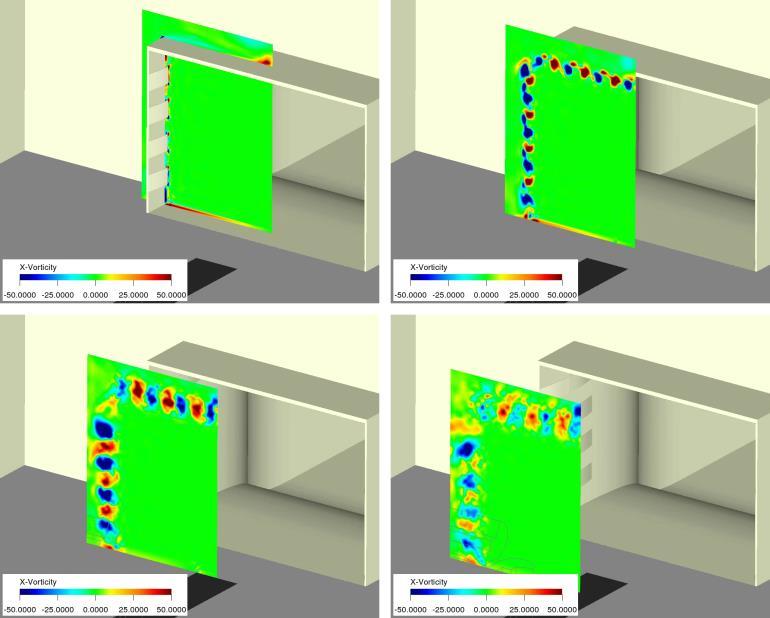
6 3.2.1 Flow-guiding elements As described above, many facilities are using specific turbulence generators at the nozzle exit, like for example the full-scale wind tunnel operated by FKFS for the last 25 years. The so-called Seiferth wings are typical primary counter measure against fluctuations. Additional harmful effects are the influence on the axial static pressure distribution and on the background noise generation. Due to the self-noise, the Seiferth wings have to be removed from the nozzle during aeroacoustic measurements. To achieve one configuration of the wind tunnel for aerodynamic as well as aeroacoustic measurements and the improve the wind tunnel performance, patented flow guidance elements [40] with a defined downstream flow angle were developed and installed in the nozzle, partially deflecting the flow (see figure 3-3 and 3-4). Due to static pressure differences between the areas with and without elements longitudinal vortices are generated on the nozzle walls and ceiling. These two mechanisms disturb the formation of coherent vortex rings farther downstream at the nozzle exit plane and thus reduce very effectively the excitation of the duct response frequencies. This effect leads to an additional stabilization of the open jet shear layer at the front of the test section (see figure 3-5). Due to its characteristics, the system of flow guiding elements is called FKFS besst (Beland silent stabilizers). Fig. 3-3: Detailed view of flow guiding elements (FKFS besst ) 7-6 STO-EN-AVT-287

7
 with the plenum hall.")
8 from the environment via the atmospheric vent openings of the plenum hall. To avoid this disadvantage, a so-called compensation channel which connects the opening in the duct (or tone hole) with the plenum hall. By this channel, the continuity of mass flow in the duct is given and the lost air is reinjected into the plenum. Hereby, the opening in the plenum has to be large to keep the recirculation in the plenum small. A conceivable location for such an approach would be between corners 1 and 2 or between the collector and corner 1. This was confirmed by, among others, Beland [41] in a 1:20 model of the aeroacoustic wind tunnel at the University of Stuttgart, see Fig Fig. 3-6: Compensation channel installed between plenum and test section diffusor [65] Helmholtz Resonator Another suitable measure can be found in one or more Helmholtz resonators in the duct or in the plenum. A Helmholtz resonator comprises a cavity with an opening and a connecting neck to the main duct flow. With proper sizing of the elements, the Helmholtz resonator can reflect acoustic out of phase back to the source, thus causing a cancellation, and prevent the acoustic energy from propagating downstream. Due to the importance of Helmholtz resonators, the most important equations for calculating the resonant frequency of the resonator can be found in the following. More details can be found in the work of Beland [41]. where c is the speed of sound, the equivalent radius of the neck with the cross-sectional area A H. V is the volume of the resonator cavity, and is the equivalent neck length of the resonator, where l r is the length of neck. The bandwidth over which a Helmholtz resonator acts can be calculated with where f o and f u represent the upper and lower cutoff frequencies. The efficiency of a resonator can be calculated with the so-called coupling factor K, which lies between 0.02 and 0.5. A larger coupling factor 7-8 STO-EN-AVT-287
 to be damped has a great influence on the effectiveness of the resonator, the coupling position of the resonator to the room is important.")
9 results in higher efficiency: Here, F K is the array factor. Since the room (plenum) to be damped has a great influence on the effectiveness of the resonator, the coupling position of the resonator to the room is important. The array factor assumes a value F K = 8 when the Helmholtz resonator is connected to a corner of the plenum. Along an edge F K is = 4, set into a wall it is 2, and under free installation (a standalone resonator) it is equal to 1. It is worth noting that the effect of the resonator decreases when the opening of the resonator is impacted by relatively strong secondary flows, as is usually the case when the resonator is installed in the rear part of the plenum hall. Fig. 3-7: Helmholtz resonator (gray cuboid in the foreground) attached to the wind tunnel plenum. 4 SOUND ABSORPTION TECHNIQUES Sound absorption techniques in aeroacoustic wind tunnels are needed mainly for two purposes: to prevent the fan and fan motor noise from propagating into the test section and to achieve an anechoic sound field as well as simultaneously reduce the noise level in the test section. There are several possibilities to achieve these requirements. 4.1 Sound Absorbers For fibrous or porous absorbers, at lower frequencies than those for which the depth of absorber material is equal to one quarter wavelength of the sound the value of absorption coefficient decreases gradually down to zero. Therefore, a relatively thick absorber is required for absorption at low frequencies. The damping effect of fibrous and porous materials can be enhanced by the use of acoustic wedges as shown in fig For good absorption, a wall treatment should have low impedance at the surface, and high internal impedance. Acoustic wedges have low impedance at the tip. The impedance increases in the propagation direction with increasing wedge thickness. STO-EN-AVT
10 Fig. 4-1: Wedges used in anechoic chambers [15] For sound absorption in test cells and laboratories porous and fibrous materials are commonly used for a long time. Also for use in aeroacoustic wind tunnels both types of material are applied. In recent years however wind tunnel absorbers were more and more designed without using fibrous materials because those tend to lose fibers due to flow exposure, which may lead to decrease of acoustic performance and furthermore to contamination of the airflow Membrane Absorbers Membrane absorbers consist of plane boxes which usually have a height of approx. 10 cm. These boxes are built up as a combination of panels designed as Helmholtz resonators. As shown in fig. 4-2 this is achieved by a set-up of hollow cassettes with a volume of approx. 0.5 to 5 liters each. These are covered with a perforated or slotted thin metal membrane. All cassettes of one box are covered with a second resonating metal membrane which replaces the mass of the air in the bottleneck of a common Helmholtz resonator. Thus, the membrane absorber box is a closed body consisting of only one material (usually stainless steel or aluminum). Tuning the absorbers to the desired frequency range is achieved via the parameters of cassette volume, thickness of the metal membranes, slot width and clearance between covering and slotted membrane. The membrane absorber is mostly used for tackling frequencies as far down as 50 or 30 Hz and up to about 250 Hz. For damping at frequencies above 250 Hz, however, the cover membranes should be extremely thin (less than 0.1 mm) STO-EN-AVT-287
11 Fig. 4-2: Basic design of a membrane absorber used in the IVK wind tunnel; 1...cassettes, 2...slotted covers, 3...membrane Compound Panel Absorber The compound panel absorber was developed as low cost low frequency absorber. They consist of large ( 1m 2 ) and thick ( 1 mm) steel plates combined with resilient micropore foam plates (Fig. 4-3) which are placed in front of a hard wall or ceiling. The system represents a broadband mass/spring and plate resonator assembly which is tuned to extremely low frequencies, typically below 100 Hz but may be extended up to 500 Hz [16]. Compound panel absorbers are mostly used for normal room acoustics (e.g. orchestra pits, rehearsal halls, offices, conference rooms, canteens), but are applied also in wind tunnels as component of broadband compact absorbers (s. chapter 4.1.3). Fig. 4-3: Structure of a compound panel absorber [16] Broadband Compact Absorber When a compound panel absorber is combined with an additional micropore foam layer (fig. 4-4) which has good absorption properties in the higher frequency range a broad frequency spectrum can be treated, as can be seen in fig These absorbers feature a very small construction depth and are widely used for anechoic test cells, vehicle acoustic test benches and also aeroacoustic wind tunnels. STO-EN-AVT
 and a compound panel absorber (CPA) [16")
12 Fig. 4-4: Structure of a broadband compact absorber [16] Fig. 4-5: Comparison of the absorption coefficients of a broadband compact absorber (BCA) and a compound panel absorber (CPA) [16] Microperforated Panel Absorber Another possibility to avoid the installation of large quantities of mineral fibres is to absorb acoustic energy within small (< 1 mm) holes or slits as illustrated in fig Microperforated absorbers operate basically like Helmholtz resonators. They can be tuned mainly by their geometrical parameters and, to a smaller extent, their thermal conductivity to a quite broadband characteristic and are widely used in room acoustics and also vehicle acoustics STO-EN-AVT-287
![Fig. 4-6: Structure of a microperforated panel absorber [16] 4.2 Silencer Design in the Duct Modern wind tunnel designs avoid fibrous material in the duct.](/docs-images/84/89284163/images/13-0.jpg "In most cases a combination of foam material (to treat the higher frequency range) and membrane or compound panel absorbers (to treat the lower frequency range) is used.")
13 Fig. 4-6: Structure of a microperforated panel absorber [16] 4.2 Silencer Design in the Duct Modern wind tunnel designs avoid fibrous material in the duct. In most cases a combination of foam material (to treat the higher frequency range) and membrane or compound panel absorbers (to treat the lower frequency range) is used. One example is the IVK wind tunnel in Stuttgart which is operated by FKFS. Two u-bent silencers (upstream and downstream of the fan) are used for the sound absorption (fig. 4-7). They consist of thin sputter plates, which contain membrane absorbers (s ) in its steel-framework. These vertical splitter plates subdivide the return duct in three sections upstream of the fan and four sections downstream of the fan. These sections have the same pressure loss and show the same noise reduction, respectively. As the membrane absorbers mainly treat the lower frequency range the turning vanes in the four corners are lined with profiled coated foam as displayed in fig Fig. 4-7: Design for attenuating the IVK wind tunnel's fan-noise by means of u-bent silencers, depicted for corners 3 and 4: (1) Partitioning of the return duct in unequal sections with the same pressure loss and acoustic transmission (2) Acoustic lining of the duct's side walls with membrane absorbers (3) Vertical splitter plates containing 2 layers of membrane absorbers in back-to-back arrangement (4) Sheet-metal turning vanes profiled with coated porous foam [17] On the suction side of a free-standing turning vane the foam thickness is constantly 40 mm. On the pressure side it varies between 20 and 160 mm. Together with a round nose and a tailed STO-EN-AVT
14 rear end the pressure-loss coefficient is below that of the unprofiled Krober vane. The smoothness and stability at the junction of foam with nose and rear end is ensured by overlaping sheet metal. The coated foam surface is insensitive to soiling and easy to clean. The reduced pressure loss coefficient of the profiled turning vanes partly compensates the additional pressure loss which is caused by the splitter plates. Fig. 4-8: Design of the sheet-metal turning vanes with coated porous foam in the IVK wind tunnel (1) Turning vane integrated in a vertical splitter plate (2) Free-standing turning vane [17] Similar techniques are applied e.g. in the Audi aeroacoustic wind tunnel where broadband compact absorbers were used in the duct and low frequency absorbers on the fan hub [18]. 4.3 Treatment of the Test Section Walls Test sections in aeroacoustic wind tunnels are designed as anechoic chambers in order to get optimized conditions for exterior sound radiation localization and low noise levels. Ideally, the walls and the ceiling should not reflect sound back into the room, which means that they should absorb 100% of the incident sound energy. To achieve an ideal free-field condition inside a room, throughout the entire ten-octave frequency range of audible sound, is a difficult task. A common method is to line the surfaces with anechoic wedges (s ). For recently built aeroacoustic wind tunnels, however, alternative methods are used as described already for the treatment of the ducts. The concept in the test section of the IVK wind tunnel is based on dividing the necessary sound attenuation up into frequency ranges. In the low frequency range (approx. from 80 to 200 Hz) the sound absorption is done by membrane absorbers. In order to absorb the middle and high frequencies as well, a second material has to be used besides the aluminum membrane-absorbers. Coated porous polyester foam of 150 mm depth was chosen, covered by a sheet metal grid. The 7-14 STO-EN-AVT-287
 Sheet metal grid (2) Porous")
![polyester foam (3) Walls of the membrane absorber cavities (4) Slotted membranes enclosing the cavities (5) Covering membrane [17] Fig.](/docs-images/84/89284163/images/15-1.jpg "4-10: Check of the anechoic characteristic for eleven 1/3-bands in the test section of the IVK aeroacoustic wind tunnel [17] Other wind tunnels")
15 combination was arranged as shown in fig Fig. 4-9: Schematic setup of a broadband absorber consisting of porous polyester foam and membrane absorbers: (1) Sheet metal grid (2) Porous polyester foam (3) Walls of the membrane absorber cavities (4) Slotted membranes enclosing the cavities (5) Covering membrane [17] Fig. 4-10: Check of the anechoic characteristic for eleven 1/3-bands in the test section of the IVK aeroacoustic wind tunnel [17] Other wind tunnels use similar techniques, mostly broadband compact absorbers, as in the wind tunnels of STO-EN-AVT
16 Ford in Cologne, Audi in Ingolstadt and GIE S2A (PSA/Renault) in Montigny le Bretonneux near Paris. The quality of the absorption is tested driving a sound source in the middle of the test section and measuring the sound pressure along several paths from the source towards the walls and the ceiling. If the sound field is anechoic, the sound pressure should decrease 6 db for each doubling of the distance. The evaluation is done for each 1/3-octave-band as shown in fig for the IVK wind tunnel. 5 NOISE SOURCES IN THE TEST SECTION 5.1 Open Jet Noise and Shear Layer Noise As long as the open jet and the shear layer do not impinge on a rigid surface it can be regarded as quadrupole noise [19]. Quadrupole noise is not very effective at low Mach numbers. Therefore the open jet in a wind tunnel is a noise source which is of minor importance and can be neglected. 5.2 Collector Noise When the shear layer hits the collector, dipole noise is generated. Dipole noise is much more effective than quadrupole noise [19]. Thus the flow impinging on the collector may be a considerable noise source in the test section. Also gaps and breathers behind the collector can be noisy when they are hit by vortices in the flow. The amount of noise depends on the surface. Foam surfaces which may be used in order to optimize the anechoic character of the test section tend to be problematic in this context. In the IVK wind tunnel flocked fabric surfaces came out to be an effective means to lower this sound source. In other investigations pile fabrics were used as wall materials for the collector surface and proved to be beneficial (fig. 5-1) [20]. Fig. 5-1: Self induced noise in a railway aeroacoustic wind tunnel with normal collector and pile fabrics coated collector [20] 5.3 Features of Closed Test Sections Some aeroacoustically used wind tunnels and model wind tunnels have closed test sections. Especially when high velocities are needed these facilities are advantageous due to high flow stability. However, closed-wall test sections do have some inherent drawbacks from an acoustical standpoint [21]. The most obvious 7-16 STO-EN-AVT-287
17 disadvantage is the reverberant sound field due to the presence of hard walls, floor, and ceiling. Nevertheless, even exterior aeroacoustic measurements can be done, if the ducts are equipped with silencers as described in 4.2. Microphone arrays with flush mounted microphones in the test section wall can be used for sound source localization [22]. 6 FAN MOTOR NOISE In most full-scale automotive wind tunnels operated today, the air is propelled by a single fan driven by an electric motor. The motor is often housed inside the fan nacelle, which avoids the connection to an external motor with a long shaft. Normally, a cycloconverter-fed synchronous motor, a normal converter synchronous motor, or a converter-supplied DC motor is used. The control of synchronous or DC motors is usually carried out by thyristor stacks. These thyristors generate large voltage and current peaks in the pole shoes of the electric motors during the excitation of the electromagnetic field. As a consequence, the pole shoes begin to vibrate, thus exciting the whole structure which results in emission of noise of harmonic nature. Fig. 6-1 and 6-2 show the acoustic comparison of two thyristor controlled wind tunnels with very similar in design and layout. The spectra in Fig. 6-1 reveals at around 300 Hz the harmonic noise pattern originating from the pole shoes of the motor. A rather smooth broad-band spectrum without significant frequency peaks is shown in Fig. 6-2 even though the wind tunnel fan also is controlled by thyristors. This is because damping material was added to the nacelle, fan stators and fan housing. The hollow fan stator blades were filled with sand, and damping material was added to the inside of the welded steel nacelle and the outside of the fan housing, increasing the damping of the entire fan support structure [21]. Fig. 6-1: In-flow background noise level of the old Porsche open jet wind tunnel [21] STO-EN-AVT
18 Fig. 6-2: In-flow background noise level of Volvo slotted-wall wind tunnel [21] 7 FAN DESIGN [23] The following remarks describe the design considerations for a quiet axial fan for a full-scale aeroacoustic automobile wind tunnel. Special emphasis is placed on the selection of the rotor and guide vane blade numbers. One of the objectives is that the circumferential modes of the pressure disturbance created by the rotor/stator interaction should not be capable of propagation. That is, the sound will not travel down the wind tunnel as a plane wave would, but rather the pressure fluctuations decay very quickly (exponentially with distance) as they travel down the wind tunnel, and essentially none of this noise reaches the test section. Rather than discuss all of the options that one faces when designing a fan, this chapter gives an example of a particular design. It is hoped that the design considerations discussed as the example is presented will be helpful and informative to the wind noise engineer. 7.1 Fan Concepts To produce a uniform airflow with a required maximum speed of more than 60 m/s, a single stage axial fan with an outside diameter of 5000 mm is used. The operating point for the empty wind tunnel or with small models has a total pressure increase of about 2500 Pa and a volumetric flow rate of approximately 700 m 3 /s. There are additional operating points with full-scale vehicles as well as with oblique incident flow (i.e., with the vehicle in a yawed condition), with which the total pressure becomes larger and the volumetric flow rate smaller. The required power of the drive motor is 2 MW measured at the fan shaft if the fan efficiency is approximately 88%. To account for internal motor losses, the fan motor power should be increased by approximately 11%. For acceleration and for special experiments, the motor should be oversized by an additional 10%. The drive motor is air-cooled. The cool air is supplied through the stator supports. The fan is mounted rigidly, without the insertion of shock mounts. However, the fan foundation is separated from the foundation of the wind tunnel. The flow side connection at the concrete air inlet and at the hub muffler takes place via cuffs and/or fabric webbing, so that the vibration isolation is very good. The forward part of the fan nacelle should be a co-rotating hemispherical cowling, so that the supports can be omitted. Alternatively, an ogive cowling can be used, which is fastened rigidly to radial supports, if these are 7-18 STO-EN-AVT-287
19 laid out in such a way with regard to number and alignment so that no measurable acoustic effect is observed. The fan housing has a length of approximately 7000 mm, not including the cowling, and is fabricated from steel sheet. A horizontal joint separates the fan housing from the motor housing. A hollow stator vane is used for removal of the cooling air as well as the supply of electricity. A horizontal housing hatch in the rotor blade area enables removal. The optimization of the rotor and the stator blade numbers - including the blade angle as well as the number of supports - results from acoustic considerations as described in the following. 7.2 General Acoustic Considerations When a wind tunnel must satisfy very rigorous acoustic demands, the fan must be viewed as the strongest single sound source in the total circuit. Unlike in conventional wind tunnels, the fan efficiency does not have the highest priority, but rather the primary emphasis is on the spectral minimization of the radiated sound power. The goal is to reach a sufficiently low sound pressure level with the lowest possible expense for sound damping measures in the test section and around the circuit. The level that is considered to be sufficiently low depends on the acoustic quality of the open jet and the characteristics of the vehicles to be tested. As a guideline, it can be said that the fan noise after reduction by the silencers in the circuit should be at a lower level in the test section than the sum of the open jet noise associated with lip noise, turbulent mixing, and collector noise. If this is achieved, subsequent successful optimization of the open jet itself will result in audibly and measurably lower total noise levels. A very detailed study and a classification of axial fan noise were made in [24], see fig. 7-1 and 7-2. The lower-frequency leading edge noise results primarily from interference with non-uniformities in the flow stream. This can result in sound power level increases of 6 to 8 db with flow speeds around the periphery of the rotor of the order of 100 m/s. Here the aerodynamically favorable design of all supports in the air stream is of particular importance. The boundary layer sounds are usually of lesser importance. Discrete tones as well as broadband noise are more prevalent with axial fans that lack stator vanes. This noise can be reduced by using relatively thin, low loss, aerodynamic blades. Tip flow noise can be reduced by minimizing the gap between the blade tip and the housing. A relative gap of d (d = fan diameter) was found to be sufficiently small [24]. This would be a gap of 5 mm with the typical geometry discussed in the examples here. A special sound problem in connection with the gap between the fan tips and the housing was reported with the wind tunnel fan at BMW-Technik GmbH [26]. In this case, removable, plastic blade tips were mounted to the blades using attachment screws, which were countersunk in radial holes of different diameters. This resulted in a tonal, cavity noise that raised the sound level at the fan outlet by 30 db at certain frequencies. In reference [25], one can find acoustic design guidelines, developed on the basis of numerous model trials. Using these guidelines, for the pressure ratio considered here, one finds that a number of rotor blades to number of stator vanes ratio of 12 to 7 appears to result in favorable acoustic performance. STO-EN-AVT
20 Fig. 7-1: Compilation of the aerodynamic noises of axial fans [24] Preliminary investigations, literature studies, and measurements from finished machines indicate that the desired maximum overall total sound pressure level corresponding to table 7-1 can be achieved at the required operating point, i. e., Q = 500 m 3 /s, p = 1200 Pa. In the case considered here a rather low-frequency fan characteristic is preferred. That is, the fundamental blade passing noise tone should lie below 100 Hz, if possible, in order to interfere as little as possible with the flow noise produced on the motor vehicle itself. Most automobile wind noise sources become a concern only over 500 Hz. Fig. 7-2: Schematic frequency spectrum of the sound emissions of an axial flow fan [24] 1: Blade passing noise and interaction noise. 2: Lower frequency leading edge noise STO-EN-AVT-287
21 3: Boundary layer and turbulence noise. The verification of the sound pressure level is performed, for example, in accordance with ISO With a special microphone probe, the sound pressure level in the wind tunnel is measured and converted to sound power level using appropriate correction factors. The probe is relatively insensitive to pressure fluctuations in the flow resulting from turbulence. It reacts mainly to acoustic waves. From the literature it is well known that the quality of the inflow has influence on the acoustic characteristics of the fan, especially on leading edge noise. The flow quality can be determined both experimentally with a model and also with the help of CFD methods. As a datum plane, for example, one can use an upstream cross-section. Because the silencers in the corner upstream of the motor may produce wakes, it should be assessed to what extent these flow disturbances decay by the time they reach the fan entrance. The sound power spectrum represented in table 7-1 will be attainable only after careful consideration of all acoustically relevant design and manufacturing parameters. Therefore, in the following, some references are given to significant construction guidelines. Table 7-1: Desired fan sound power level (A-weighted values) for Q = 500 m 3 /s. 7.3 Optimization of the Blade Passing Noise and the Interaction Noise The separation of blade passing noise from the interaction noises is difficult, because both exist at essentially the same frequencies. This group of sounds with its tonal contribution determines the total fan sound pressure spectrum, cf. fig The increase over other noise sources is typically 15 to 20 db. The blade passing noise results solely from the rotor blades. Periodic pressure variations are produced in the surrounding space by the rotating vane-bound power field with the frequency f BPF n B (8.1) where f BPF is the blade passing frequency, n is the order of the harmonic, is the impeller rotational speed, and B is the number of rotor blades. The interaction noise develops from the interplay between the impeller blades and the stator vanes or, in multi-stage fans, from interactions between the stages. The pressure field resulting from these interactions rotates at a frequency of: f Int m B (8.2) where m indicates the mode number of the rotating pressure field. The case m = 0 (the fundamental mode) represents a uniform wave, i.e., where the pressure is uniform over the entire surface of the impeller circumference. For a fan without stator vanes, one has m = B, so that the pressure field rotates with exactly STO-EN-AVT
22 the same speed as the impeller itself. On the other hand, if stator vanes are present, with V = the number of stator vanes, then the following modes are excited [27]: m nb kv k,..., (8.3) If, for example, B = V or an integral multiple of it, then the fundamental mode with m = 0 becomes particularly excited. This means high tonal contributions occur at the rotational frequency and at its higher harmonics. In contrast to the fundamental mode, not all of the calculated possible modes can actually propagate down the wind tunnel. Depending upon whether the Mach number of the rotating pressure field is supersonic or subsonic, one can determine that a mode can propagate or that it cannot propagate (but rather decays exponentially as it travels axially down the wind tunnel). It is the goal of the fan optimization therefore to energize as restrictively as possible only the higher modes, which cannot propagate anyway. The corresponding calculations were carried out following References [27] and [28]. Fig. 7-3a and 7-3b show results for an example of a fan with the geometries used here (D = 5000 mm, d = 2500 mm) with the impeller/stator blade numbers (B/V) of 12/7 and 20/27. The volumetric flow rate was 500 m 3 /s. One sees from fig. 8.3 that for the combination B/V = 20/27, the second rotational overtone (n = 3) can propagate. For B/V = 20/27, the fundamental (n = 1) and first overtone (n = 2) modes only propagate if the fan speed is above 500 min -1. In contrast, for B/V = 12/7, starting at 300 min - 1, the fundamental mode (n = 1) and all higher harmonics can propagate. Fig. 7-4a and 7-4b show the influence of additional radial modes, u, on the propagation ability of the blade passing noise tones. The quantity u indicates the number of the radial wavelengths in the vane channel. The more radial modes that appear, the greater the number of modes fall into the cut-off area. The calculations were performed in accordance with the procedure in [27]. The charts in fig. 7-4 are to be understood in the following way, that no modes can propagate (that is, the modes are "cut-off") beneath the lines u = constant. This cut-off criterion is satisfied for higher harmonics of the blade passing noise if additional radial modes, indicated by u, are present. Heesen's experiments [29] showed that the most effective method of eliminating blade passing noise was to produce higher order circumferential modes (higher m) that cannot propagate, as indicated in fig Fig. 7-3a: Modes capable of propagation as a function of fan speed and frequency. The solid squares indicate where each mode is capable of propagation. B/V = 12/ STO-EN-AVT-287
23 Fig. 7-3b: As fig. 8.3a except that B/V = 20/27. Fig. 7-4a: Cut-off criteria as a function of the axial and radial mode numbers, B/V = 12/7. STO-EN-AVT
.")
24 Fig. 7-4b: As fig. 8.4a except that B/V = 20/27. Fig. 7-4a and 7-4b were obtained for a fan speed of 350 rpm and rotor/stator blade number combinations (B/V) of 12/7 and 20/27. From an inspection of fig. 7-4b, one observes for B/V = 20/27 that the fundamental and first overtones are cut-off for u = 0 (i.e., the cut-off of the n = 1 and n = 2 modes is guaranteed). However, for the example with the blade/vane ratio of B/V = 12/7 (see fig. 7-4a), u = 1 is required to cut-off the fundamental and first overtone. In the existing case the radial mode number up to u = 5 was calculated so that the propagation behavior could be determined up to the harmonic n = 6. Physically, radial modes could be produced by a phase lag between rotor and the hub. To implement this one could require diagonally positioned (not radial) guide vanes, sweep of the rotor rear edge and the stator front edge, or a radial twist of the rotor blades. The resulting fan configuration is shown in table 7-2 in connection with fig. 7-5 for the variant B/V = 20/14. Table 7-2: Examples of Parameters Selected for a Wind Tunnel Fan with B/V = 20/14 to Achieve the Production of Radial Modes of the Order u = 5. In reality, a wind tunnel fan design that deviates from the criteria shown in table 7-2 may yet result in a fan with low blade passing noise. This is because there are design factors of secondary importance, for example, the spacing between the rotor and stator. In the design listed in table 7-2, the rotor/stator spacing was designed predominantly for acoustic criteria and not for maximum efficiency. However, after [29], it is generally sufficient for the normalized rotor/stator distance s to satisfy the following requirement for noise considerations: s s' (7.4) L 2L r s where s b / 2 is the rotor/stator spacing. L r is the rotor chord, and L s is the stator chord. With s = C sp 7-24 STO-EN-AVT-287
25 1000 mm (see table 7-2), a supposed rotor chord length of L r = 354 mm (average) and a stator chord length of L s = 1000 mm, one obtains a value of s = This is clearly over the limiting value from equation (7.4). Hence, reduction of the rotor/stator spacing may possibly increase the efficiency without increasing the interaction noise noticeably. Fig. 7-5: Rotor-Stator Arrangement 8 TURNING VANES The corner turning vanes may contribute to the self induced noise measured in the test section. Especially the vanes #1 and #2 downstream of the test section may cause problems in this context due to the higher flow velocities there in comparison to the upstream vanes #3 and #4. In most cases, the flow noise from corners #3 and #4 can be ignored [21]. If the duct is treated like described in 4.2 also the noise from corners #1 and #2 can be neglected. In general, the vane must be designed free of flow separation in order to minimize overall corner vane noise. The turning vanes must be aerodynamically properly shaped. Steps and gaps on the surface must be avoided since these will generate excessive noise. Corner vane noise for thin corner vanes can be estimated from the correlation given in equation (8.1) [30]: L Woct L W 18 10log f0 50log v 10log S 10log C 10log n c (8.1) where L Woct = the octave-band sound power level (db re watts) f o v c = the octave-band center frequency (Hz) = the flow velocity between the vanes found from equation (8.2) (m/s) S = the duct cross-sectional area (m 2 ) C n = the vane chord length (m) = the number of turning vanes ΔL W = the characteristic spectrum found from equation (8.3) The flow velocity between the vanes can be found using the expression: STO-EN-AVT
26 v c 1 k 1 k v 2 v for for k 1 k 1 (8.2) where k = the corner loss factor = 1.67 Δp/v 2 Δp = total pressure loss (N/m 2 ) v = the duct velocity (m/sec) The characteristic spectrum is found from the following expression: log St (8.3) L W where St = the Strouhal number, f 0 d v c q d q = the duct dimension perpendicular to the vane length (m) 9 SETTLING CHAMBER 9.1 Screens Screens are located in a section of the wind tunnel where flow velocities are relatively small. This applies in particular when the contraction ratio is high, e.g. higher than about 6:1, which is the case for many facilities. Low velocities generate only low noise levels. Therefore, screen-generated noise can be neglected in most cases. The overall sound power level L W for wire meshes can be estimated using equation (9.1) [31]: L W log d 67.7log v 10log n 10log A (9.1) w where d w v n = the wire diameter (m) = the mean duct velocity at the location of the screens (m/s) = the number of screens in series A = the cross-sectional area at the location of the screens (m 2 ) The main peak frequency f in the spectrum may be estimated using equation (9.2) with a Strouhal number St 7-26 STO-EN-AVT-287
27 of 0.2, wind speed v and wire diameter d w. f St v d w (9.2) 9.2 Heat Exchangers Many, also non-climatic, closed-circuit wind-tunnel facilities feature heat exchangers to balance heat production due to energy dissipation. Generally, these devices are located in the settling chamber where the cross sectional area attains a maximum, in order to minimise pressure losses. Consequently, the sound power they generate can propagate towards the nozzle and the plenum chamber without undergoing any substantial acoustic damping. In contrast, some tunnels like the BMW-Technik Aeroacoustic Wind Tunnel have the heat exchanger in their return duct embedded in mufflers. When estimating the overall sound-power level L W of settling-chamber inserts, usually equation (9.3) is used: L W log k 10log A 60log Ma (9.3) with k = pressure-loss coefficient; A = cross section in m 2 ; Ma = local Mach Number. Originally equation (9.3) was derived for screens. It turned out however, that it may also serve as a first approximation for other obstacles of matrix-type. Above all, it shows basic dependencies with respect to velocity and geometry, which are absolutely required when scaling results for different flow conditions. Nevertheless, no spectral information is provided by equation (9.3). Furthermore, though the production of acoustic energy is related to the pressure-loss coefficient k, there is no reference to the structure of the turbulent wake and the length-scales involved. This may serve as an explanation why equation (9.3) cannot account for the specific design of an individual heat exchanger. In conjunction with the scale-model experiments during the design phase of the Audi Aero-Acoustic Wind Tunnel [32], extensive experimental investigations were conducted to improve the knowledge on the influence of heat-exchanger design parameters on the acoustic performance of the facility. Among the parameters considered were the number and arrangement of tube rows, tube design, arrangement of fins etc. Fig. 9-1 displays data measured with two different heat exchangers of k = 1.55; A = 1 m 2 and Ma = According to equation (9.3), in both cases the overall sound-power level should amount to L W = 70.2 db. However, the design of the two specimens was quite different. Though there were elliptic tubes in both cases, they were differently arranged, i.e. in a single staggered row and in two straight rows, respectively. One sample had fins, one didn't. From the diagram it can be detected that not only the overall sound-power level differs but, more important, the spectral content varies. At low frequencies, say below 100 Hz, which are primarily important for the overall level, there are fairly small differences between both configurations. This may, at least to a certain extent, be due to residual fan-noise contributions from the experimental set-up. However, the importance of these bands diminishes when A-weighting is applied. Substantial differences occur at about 250 Hz, were even tonal noise became audible in the case were no fins were present. In the higher frequency range, i.e. above 1200 Hz, broadband noise generation is more powerful in the case of fins. This may be attributed to the effect of wall-shear stress acting on the fins, whereas tonal-noise generation seems to be attenuated due to a lack of coherence. As one result of these experiments it may be concluded that staggered row heat exchangers featuring fins of not too small distance appear to be advantageous. STO-EN-AVT
28 Fig. 9-1: 1/3-Octave Spectrum of Heat Exchanger Noise [21] For practical applications in wind tunnels, apart from thermodynamic aspects, the acoustic radiator performance in the middle and upper frequency range may be important in some cases. In the low-frequency range, even in the case of silenced ducts, other noise sources often still tend to be dominating. Besides radiator design the settling-chamber environment has to be considered, as well. Experiments revealed that noise contributions of screens and honeycombs, which are often small compared to those of the heat exchanger, may be amplified when exposed to a turbulent flow like the radiator wake. Therefore, the distance between individual elements has to be carefully optimised. If this is disregarded, even the benefits of an advantageous heat-exchanger design may be easily overcompensated. 10 TURBULENCE AND SIDE WIND GUST SIMULATION Although the aeroacoustic development of cars is still mainly done with smooth flow conditions in specially designed wind tunnels, there has been an increasing interest during the last years to investigate wind noise under realistic on-road flow conditions [33] because the wind noise caused by the flow around the vehicle depends on speed and wind direction. The on-road-flow vector under real atmospheric conditions is however locally and temporally not constant. In the case of road measurements the flow vector results from the overlay of the vehicle speed and the atmospheric wind velocity. Due to different climatic and local conditions (e.g. hilly or plane scenery with or without trees, guard rails and traffic) the flow conditions and turbulence degrees vary strongly [34,35]. Changes of speed affect the interior noise as a change of the sound pressure level, thus the sound signal becomes amplitude-modulated. A change of the incident flow direction causes a change of the frequency spectrum, because local flow conditions along the vehicle are changing (e.g. A-pillar, mirror) due to global side wind. In this case, the interior noise will be amplitude and frequency modulated STO-EN-AVT-287
![Low-frequency amplitude modulations are noticed by the human perception particularly sensitive as fluctuating noise [36] and are felt by humans more unpleasant compared to constant noises.](/docs-images/84/89284163/images/29-0.jpg "For development work in the wind tunnel it is necessary to clarify the influence of turbulence on the averaged interior noise spectra of the car, and whether turbulences in the flow are relevant")
29 Low-frequency amplitude modulations are noticed by the human perception particularly sensitive as fluctuating noise [36] and are felt by humans more unpleasant compared to constant noises. For development work in the wind tunnel it is necessary to clarify the influence of turbulence on the averaged interior noise spectra of the car, and whether turbulences in the flow are relevant concerning the wind noise perception. In some wind tunnels, tests with vortex generators were performed [33,37,38]. In the Pininfarina wind tunnel moving wings (s. fig. 10-1) are used. However, when turbulence generators are used they should be well shaped and large enough to produce sufficiently large eddies, which should be verified mandatoryly. Even relatively big obstacles in the settling chamber may not be sufficient. Fig. 10-1: Turbulence generators in the Pininfarina wind tunnel [37] Another possibility to detect the acoustic sensitivity of a vehicle to turbulence which was practised at FKFS in Stuttgart is to measure the interior noise during a sweep over different yaw angles [38]. This sweep covers a range of at least -20 to +20 because these angles could occur during strong turbulence on road. Fig and 10-3 show the results of two yaw sweeps from -20 to +20 (driver seat, outer ear) for two upper class cars, one vehicle which is rated positively concerning acoustic behaviour in turbulent flow on road and another which is polled badly. The plots illustrate the interior noise spectra versus the yaw angle. The A- weighted sound pressure level is coded by color, black indicates low levels, yellow colour high levels. The black line marks roughly the trend of the position of a constant level (about 10 db(a)) in a frequency band where aerodynamic sound is dominating and thus reveals the gradient of the aeroacoustic impact over the yaw angle. It can be clearly seen that the sound pressure rise in this frequency span at higher yaw angles differs significantly between the two vehicles. The gradient of the sound pressure level for the positively rated car in Fig is not as high as for the negatively rated car, shown in Fig Also the yaw region where the interior noise is quite constant is different. This aspect indicates that the positively rated car is less sensitive to turbulence caused by changes of the yaw angle than the negatively rated car. STO-EN-AVT
 versus yaw angle for a positively rated upperclass car 10k 9k Lee side wind influence region of constant noise Luv side wind influence 8k 7k 6k f/hz 5k")
30 10k 9k 8k Lee side wind influence region of constant noise Luv side wind influence 7k 6k f/hz 5k 4k 3k 2k 1k / Fig. 10-2: Interior noise (driver seat, outer ear) versus yaw angle for a positively rated upperclass car 10k 9k Lee side wind influence region of constant noise Luv side wind influence 8k 7k 6k f/hz 5k 4k 3k 2k 1k / Fig. 10-3: Interior noise (driver seat, outer ear) versus yaw angle for a negatively rated upper STO-EN-AVT-287

![As mentioned above, an increasing interest to investigate wind noise under realistic on-road flow conditions can be observed (e.g. [42]).](/docs-images/84/89284163/images/31-1.jpg "Particularly the increasing demand for even more comfort and thus the need for enhanced psychoacoustic evaluations underline this trend.")
31 class car. Thus, the yaw angle sweep is a good and cost-efficient means to describe the acoustic sensitivity of a vehicle to turbulence. The modification of the spectra vs. yaw angle can be used to characterize the aeroacoustic behaviour of different vehicles under turbulent flow conditions as on road. As mentioned above, an increasing interest to investigate wind noise under realistic on-road flow conditions can be observed (e.g. [42]). Particularly the increasing demand for even more comfort and thus the need for enhanced psychoacoustic evaluations underline this trend. Thus, to be able to simulate typical unsteady flow scenarios with regard to aeroacoustics and aerodynamics, new active side-wind gust and turbulence generators have been developed. One example is the system which has been implemented in the full-scale aeroacoustic wind tunnel of Stuttgart University. The system, called FKFS swing (side wind generator), consists of 8 wing profiles vertically positioned at the nozzle exit (see figure 10-4). Each profile is operated by its own drive, among others by signals measured on the road. Fig. 10-4: FKFS Side Wind Generator swing in the wind tunnel [43]. The maximum flow deflection and the maximum frequency which are necessary to reproduce typical onroad situations for aeroacoustics have been determined by on-road measurements as well as considering psychoacoustic aspects. The maximum frequency amounts to 10 Hz with a maximum deflection angle at the vehicle of ca. 3. For lower frequencies larger deflection angles are possible. For vehicle tests, usually time history data from on-road measurements or artificially generated signals are used. To reproduce the flow angle at the vehicle in the wind tunnel accurately as on the road, the transfer function of the whole system from data input to flow at the vehicle has to be known. Once determined and using the inverse of this transfer function, the on-road flow situation in terms of yaw angle can be reproduced accurately by the system. A comparison between on-road time history (blue solid line) and its reproduction STO-EN-AVT
Silencers. Transmission and Insertion Loss
 Silencers Practical silencers are complex devices, which operate reducing pressure oscillations before they reach the atmosphere, producing the minimum possible loss of engine performance. However they
Root Cause Analysis of a vibration problem in a propylene turbo compressor. Pieter van Beek, Jan Smeulers
 Root Cause Analysis of a vibration problem in a propylene turbo compressor Pieter van Beek, Jan Smeulers Problem description A newly installed turbo compressor system for propylene showed vibrations in
Interior Duct Wall Pressure Downstream of a Low-Speed Rotor
 14th AIAA/CEAS Aeroacoustics Conference (29th AIAA Aeroacoustics Conference) 5-7 May 2008, Vancouver, British Columbia Canada AIAA 2008-2893 Interior Duct Wall Pressure Downstream of a Low-Speed Rotor
Special edition paper
 Countermeasures of Noise Reduction for Shinkansen Electric-Current Collecting System and Lower Parts of Cars Kaoru Murata*, Toshikazu Sato* and Koichi Sasaki* Shinkansen noise can be broadly classified
Design and Test of Transonic Compressor Rotor with Tandem Cascade
 Proceedings of the International Gas Turbine Congress 2003 Tokyo November 2-7, 2003 IGTC2003Tokyo TS-108 Design and Test of Transonic Compressor Rotor with Tandem Cascade Yusuke SAKAI, Akinori MATSUOKA,
Compressor Noise Control
 Purdue University Purdue e-pubs International Compressor Engineering Conference School of Mechanical Engineering 1972 Compressor Noise Control G. M. Diehl Ingersoll-Rand Research Follow this and additional
Noise Resist. - you need to improve the noise reduction of your existing sound enclosure
 Noise Resist Is this your situation? - you need to reduce the noise emission of your machinery - you need to improve the noise reduction of your existing sound enclosure - you do not want delicate foam
Study on Flow Fields in Variable Area Nozzles for Radial Turbines
 Vol. 4 No. 2 August 27 Study on Fields in Variable Area Nozzles for Radial Turbines TAMAKI Hideaki : Doctor of Engineering, P. E. Jp, Manager, Turbo Machinery Department, Product Development Center, Corporate
ABSTRACT INTRODUCTION
 Wind tunnel investigation of waste air re-entry with wall ventilation P. Broas Technical Research Centre of Finland, Ship Laboratory, Tekniikantie 12, SF-02150, Espoo, Finland ABSTRACT A wind tunnel investigation
Numerical simulation of detonation inception in Hydrogen / air mixtures
 Numerical simulation of detonation inception in Hydrogen / air mixtures Ionut PORUMBEL COMOTI Non CO2 Technology Workshop, Berlin, Germany, 08.03.2017 09.03.2017 Introduction Objective: Development of
INTERIOR NOISE OF A KOREAN HIGH-SPEED TRAIN IN TUNNELS
 INTERIOR NOISE OF A KOREAN HIGH-SPEED TRAIN IN TUNNELS Sunghoon Choi, Chan-Woo Lee, Jae-Chul Kim, and Joon-Ho Cho Noise and Vibration Research Group, Korea Railroad Research Institute, Woulam-dong, Uiwang-city,
Vehicle Aerodynamics Subscription Development of Numerical Simulation Method of Flow Around Automobile Using Meshfree Method
 Vehicle Aerodynamics Subscription 2005-01-0544 Development of Numerical Simulation Method of Flow Around Automobile Using Meshfree Method 2005-01-0545 A Downforce Optimization Study for a Racing Car Shape
Abstract INTRODUCTION
 Abstract The facility for acoustic tests of universal propulsion simulators (UPS) in conditions of anechoic chamber is created in Central Institute of Aviation Motors (Moscow). The facility is designed
Analysis of aerodynamic and aeroacoustic behaviour of a simplified high-speed train bogie
 Analysis of aerodynamic and aeroacoustic behaviour of a simplified high-speed train bogie J.Y. Zhu 1, Z.W. Hu 1, D.J. Thompson 2 1 Aerodynamics and Flight Mechanics Research Group, Faculty of Engineering
REVIEW ON NOISE AND VIBRATION IN AUTOMOBILES
 REVIEW ON NOISE AND VIBRATION IN AUTOMOBILES AZAR R. INAMDAR 1, PRANITA A. DESHPANDE 2, SWAPNALI R. GADEKAR 3 1,2,3 Department of Mechanical Engineering, Sandip Foundation s, Sandip Institute of Technology
A Different Approach to Gas Turbine Exhaust Silencing
 74-GT-26 Copyright 1974 by ASME $3.00 PER COPY $1.00 TO ASME MEMBERS The Society shall not be responsible for statements or opinions advanced in papers or in discussion at meetings of the Society or of
e t Performance of Extended Inlet and Extended Outlet Tube on Single Expansion Chamber for Noise Reduction
 e t International Journal on Emerging Technologies 7(1): 37-41(2016) ISSN No. (Print) : 0975-8364 ISSN No. (Online) : 2249-3255 Performance of Extended Inlet and Extended Outlet Tube on Single Expansion
Acoustic design of the air transparent soundproofing wall
 PROCEEDINGS of the 22 nd International Congress on Acoustics Materials for Noise Control: Paper ICA2016-323 Acoustic design of the air transparent soundproofing wall Seong-Hyun Lee (a), Junghwan Kook (b),
SILENCER SELECTION INSTRUCTIONS
 For general information in HVAC Acoustics, consult the following publications: 2013 ASHRAE Fundamentals Handbook, Chapter 8 Sound and Vibration 2011 ASHRAE Applications Handbook, Chapter 48 Noise and Vibration
Part C: Electronics Cooling Methods in Industry
 Part C: Electronics Cooling Methods in Industry Indicative Contents Heat Sinks Heat Pipes Heat Pipes in Electronics Cooling (1) Heat Pipes in Electronics Cooling (2) Thermoelectric Cooling Immersion Cooling
STUDY OF THE AERODYNAMIC NOISE CHARACTERISTICS OF BLUFF BODIES AS A PANTOGRAPH MEMBER
 STUDY OF THE AERODYNAMIC NOISE CHARACTERISTICS OF BLUFF BODIES AS A PANTOGRAPH MEMBER PACS REFERENCE: 43.5.Lj IKEDA Mitsuru Railway Technical Research Institute -8-38, Hikari-cho, Kokubunji-shi, Tokyo,
A STUDY OF THE CENTRIFUGAL COMPRESSOR DISCHARGE PIPELINE CONSTRAINED OSCILLATION. KIRILL SOLODYANKIN*, JIŘÍ BĚHAL ČKD KOMPRESORY, a.s.
 A STUDY OF THE CENTRIFUGAL COMPRESSOR DISCHARGE PIPELINE CONSTRAINED OSCILLATION KIRILL SOLODYANKIN*, JIŘÍ BĚHAL ČKD KOMPRESORY, a.s. Abstract: The paper presents a solution of a pipeline constrained oscillation
Cooling Enhancement of Electric Motors
 Cooling Enhancement of Electric Motors Authors : Yasser G. Dessouky* and Barry W. Williams** Dept. of Computing & Electrical Engineering Heriot-Watt University Riccarton, Edinburgh EH14 4AS, U.K. Fax :
AN INTAKE SILENCER FOR THE CONTROL OF MARINE DIESEL TURBOCHARGER COMPRESSOR NOISE
 AN INTAKE SILENCER FOR THE CONTROL OF MARINE DIESEL TURBOCHARGER COMPRESSOR NOISE Liu Chen, Cao Yipeng, Zhang Wenping and Zhao Xiaochen Harbin Engineering University, College of Power and Energy Engineering,
Aerodynamic Characteristics of Sedan with the Rolling Road Ground Effect Simulation System
 Vehicle Engineering (VE) Volume 2, 2014 www.seipub.org/ve Aerodynamic Characteristics of Sedan with the Rolling Road Ground Effect Simulation System Yingchao Zhang 1, Linlin Ren 1, Kecheng Pan 2, Zhe Zhang*
Chapter 1: Introduction to Automobile Aerodynamics...1
 Preface...xv Acknowledgments...xix Chapter 1: Introduction to Automobile Aerodynamics...1 1.1 Scope... 1 1.1.1 The Role of Aerodynamics in Vehicle Design... 1 1.1.2 The Character of Vehicle Aerodynamics...
Noise Reduction in a Reciprocating Compressor by Optimizing the Suction Muffler
 Noise Reduction in a Reciprocating Compressor by Optimizing the Suction Muffler Katakama Nagarjuna ¹ K.Sreenivas² ¹ M.tech student, ²Professor, dept of mechanical engineering kits, markapur, A.P, INDIA
CHAPTER 6 MECHANICAL SHOCK TESTS ON DIP-PCB ASSEMBLY
 135 CHAPTER 6 MECHANICAL SHOCK TESTS ON DIP-PCB ASSEMBLY 6.1 INTRODUCTION Shock is often defined as a rapid transfer of energy to a mechanical system, which results in a significant increase in the stress,
Generators for the age of variable power generation
 6 ABB REVIEW SERVICE AND RELIABILITY SERVICE AND RELIABILITY Generators for the age of variable power generation Grid-support plants are subject to frequent starts and stops, and rapid load cycling. Improving
Prof. João Melo de Sousa Instituto Superior Técnico Aerospace & Applied Mechanics. Part B Acoustic Emissions 4 Airplane Noise Sources
 Prof. João Melo de Sousa Instituto Superior Técnico Aerospace & Applied Mechanics Part B Acoustic Emissions 4 Airplane Noise Sources The primary source of noise from an airplane is its propulsion system.
Chapter 7: Basic Vibration Control: Reduction at source (Part III)
") Chapter 7: Basic Vibration Control: Reduction at source (Part III) Noise and vibration generated by fluid flow In fluid mechanics, turbulence refers to disturbance in a flow, which under other circumstances
Chapter 7: Basic Vibration Control: Reduction at source (Part III) Noise and vibration generated by fluid flow In fluid mechanics, turbulence refers to disturbance in a flow, which under other circumstances
SILENCER SELECTION INSTRUCTIONS
 SILENCER SELECTION INSTRUCTIONS For general information in HVAC Acoustics, consult the following publications: > > 07 ASHRAE Fundamentals Handbook, Chapter 8 Sound and Vibration > > 05 ASHRAE Applications
(Refer Slide Time: 1:13)
") Fluid Dynamics And Turbo Machines. Professor Dr Dhiman Chatterjee. Department Of Mechanical Engineering. Indian Institute Of Technology Madras. Part A. Module-2. Lecture-2. Turbomachines: Definition and
Fluid Dynamics And Turbo Machines. Professor Dr Dhiman Chatterjee. Department Of Mechanical Engineering. Indian Institute Of Technology Madras. Part A. Module-2. Lecture-2. Turbomachines: Definition and
Seeing Sound: A New Way To Reduce Exhaust System Noise
 \ \\ Seeing Sound: A New Way To Reduce Exhaust System Noise Why Do You Need to See Sound? Vehicle comfort, safety, quality, and driver experience all rely on controlling the noise made by multiple systems.
Inductive Power Supply (IPS ) for the Transrapid
 for the Transrapid") Inductive Power Supply (IPS ) for the Transrapid M. Bauer, P. Becker & Q. Zheng ThyssenKrupp Transrapid GmbH, Munich, Germany ABSTRACT: At velocities below 100 km/h and during stops the Transrapid vehicle
Inductive Power Supply (IPS ) for the Transrapid M. Bauer, P. Becker & Q. Zheng ThyssenKrupp Transrapid GmbH, Munich, Germany ABSTRACT: At velocities below 100 km/h and during stops the Transrapid vehicle
inter.noise 2000 The 29th International Congress and Exhibition on Noise Control Engineering August 2000, Nice, FRANCE
 Copyright SFA - InterNoise 2000 1 inter.noise 2000 The 29th International Congress and Exhibition on Noise Control Engineering 27-30 August 2000, Nice, FRANCE I-INCE Classification: 7.6 ROLLING NOISE FROM
Development of Shape of Helmholtz Resonator Cavity for Attenuation of Low Frequency Noise of Pure Reactive Muffler
 Development of Shape of Helmholtz Resonator Cavity for Attenuation of Low Frequency Noise of Pure Reactive Muffler Amit Kumar Gupta 1, Nirmal Gupta 2 1 Assistant Professor, 2 M.E. Scholar Mechanical Engineering
Investigation of converging slot-hole geometry for film cooling of gas turbine blades
 Project Report 2010 MVK160 Heat and Mass Transport May 12, 2010, Lund, Sweden Investigation of converging slot-hole geometry for film cooling of gas turbine blades Tobias Pihlstrand Dept. of Energy Sciences,
Chapter 7: Thermal Study of Transmission Gearbox
 Chapter 7: Thermal Study of Transmission Gearbox 7.1 Introduction The main objective of this chapter is to investigate the performance of automobile transmission gearbox under the influence of load, rotational
Pulsation dampers for combustion engines
 ICLASS 2012, 12 th Triennial International Conference on Liquid Atomization and Spray Systems, Heidelberg, Germany, September 2-6, 2012 Pulsation dampers for combustion engines F.Durst, V. Madila, A.Handtmann,
Location of Noise Sources in Fluid Power Machines
 International Journal of Occupational Safety and Ergonomics (JOSE) 2007, Vol. 13, No. 4, 441 450 Location of Noise Sources in Fluid Power Machines Wiesław Fiebig Institute of Machine Design, Wrocław University
Dynamic characteristics of railway concrete sleepers using impact excitation techniques and model analysis
 Dynamic characteristics of railway concrete sleepers using impact excitation techniques and model analysis Akira Aikawa *, Fumihiro Urakawa *, Kazuhisa Abe **, Akira Namura * * Railway Technical Research
CER/EIM Position Paper Ballast Pick-up due to Aerodynamic Effects. October Version 1.0
 CER/EIM Position Paper Ballast Pick-up due to Aerodynamic Effects October 2015 Version 1.0 Introduction Aerodynamic loads on the trackbed generated by the passing of trains at high speed may cause individual
WHITE PAPER. Flow Induced Noise Reduction Techniques for Microphones in Low Speed Wind Tunnels
 Flow Induced Noise Reduction Techniques for Microphones in Low Speed Wind Tunnels Andrew R. Barnard, Ph.D., INCE Bd. Cert. Assistant Professor, Mechanical Engineering Engineering Mechanics Michigan Technological
MECHANICAL EQUIPMENT. Engineering. Theory & Practice. Vibration & Rubber Engineering Solutions
 MECHANICAL EQUIPMENT Engineering Theory & Practice Vibration & Rubber Engineering Solutions The characteristic of an anti-vibration mounting that mainly determines its efficiency as a device for storing
CHAPTER 5 ANALYSIS OF COGGING TORQUE
 95 CHAPTER 5 ANALYSIS OF COGGING TORQUE 5.1 INTRODUCTION In modern era of technology, permanent magnet AC and DC motors are widely used in many industrial applications. For such motors, it has been a challenge
VIBRATION OF AUTOMOBILE SIDE VIEW MIRROR DUE TO AERODYNAMIC INPUTS
 Proceedings of the International Conference on Mechanical Engineering 25 (ICME25) 28-3 December 25, Dhaka, Bangladesh ICME5- VIBRATION OF AUTOMOBILE SIDE VIEW MIRROR DUE TO AERODYNAMIC INPUTS Rajneesh
Development of Rattle Noise Analysis Technology for Column Type Electric Power Steering Systems
 TECHNICAL REPORT Development of Rattle Noise Analysis Technology for Column Type Electric Power Steering Systems S. NISHIMURA S. ABE The backlash adjustment mechanism for reduction gears adopted in electric
A Practical Guide to Free Energy Devices
 A Practical Guide to Free Energy Devices Part PatD11: Last updated: 3rd February 2006 Author: Patrick J. Kelly Electrical power is frequently generated by spinning the shaft of a generator which has some
Active vibration reduction applied to the compressor of an air-conditioning unit for trams
 Active vibration reduction applied to the compressor of an air-conditioning unit for trams J. Bös, E. Janssen, M. Kauba and D. Mayer Fraunhofer Institute for Structural Durability and System Reliability
APPLICATION OF STAR-CCM+ TO TURBOCHARGER MODELING AT BORGWARNER TURBO SYSTEMS
 APPLICATION OF STAR-CCM+ TO TURBOCHARGER MODELING AT BORGWARNER TURBO SYSTEMS BorgWarner: David Grabowska 9th November 2010 CD-adapco: Dean Palfreyman Bob Reynolds Introduction This presentation will focus
EXPERIMENTAL RESEARCH ON HELICOPTER TAIL SHAKE PHENOMENON
 EXPERIMENTAL RESEARCH ON HELICOPTER TAIL SHAKE PHENOMENON Iskandar Shah Ishak, Shuhaimi Mansor, Tholudin Mat Lazim Department of Aeronautical Engineering, Faculty of Mechanical Engineering, Universiti
Power Conditioning of Microgrids and Co-Generation Systems
 Power Conditioning of Microgrids and Co-Generation Systems Nothing protects quite like Piller piller.com Content 1 Introduction 3 2 Basic requirements of a stable isolated network 3 3 Requirements for
Interior Acoustics. Lecture delivered by: Kiran V. R. Asst. Prof. Dept. of AAE MSRSAS-Bangalore. M.S Ramaiah School of Advanced Studies - Bangalore
 Interior Acoustics Lecture delivered by: Kiran V. R. Asst. Prof. Dept. of AAE MSRSAS-Bangalore Outline of the Presentation Introduction to acoustics Different noise sources Types of vehicle noise Human
Sound attenuators. Sound attenuators, Sound attenuating louvres. Sound attenuators. Rectangular sound attenuators DZ-2, DZ-3
 , Sound attenuating louvres Rectangular sound attenuators DZ-2, DZ-3 Application are designed to attenuate noises of fans and air-conditioning devices in ventilation and air-conditioning installations.
CAV controllers. Type VFL. Volume flow limiter for insertion into ducting K
 .1 X X testregistrierung CAV controllers Type Aerodynamic damper blade Sticker showing volume flow rates Set the volume flow rate Insert Volume flow limiter for insertion into ducting Circular, mechanical
THE INSTITUTE OF PAPER CHEMISTRY, APPLETON, WISCONSIN
 THE INSTITUTE OF PAPER CHEMISTRY, APPLETON, WISCONSIN HIGH SPEED PHOTOGRAPHY OF THE DISK REFINING PROCESS Project 2698 Report 5 To The Technical Division Fourdrinier Kraft Board Group of the American Paper
Plasma Assisted Combustion in Complex Flow Environments
 High Fidelity Modeling and Simulation of Plasma Assisted Combustion in Complex Flow Environments Vigor Yang Daniel Guggenheim School of Aerospace Engineering Georgia Institute of Technology Atlanta, Georgia
COMPUTATIONAL FLUID DYNAMICS ANALYSIS OF THE ACOUSTIC PERFORMANCE OF VARIOUS SIMPLE EXPANSION CHAMBER MUFFLERS
 COMPUTATIONAL FLUID DYNAMICS ANALYSIS OF THE ACOUSTIC PERFORMANCE OF VARIOUS SIMPLE EXPANSION CHAMBER MUFFLERS Middelberg, J.M., Barber, T.J., Leong, S. S., Byrne, K.P and Leonardi, E. School of Mechanical
QUIET-TRACK: Track optimisation and monitoring for further noise reduction
 QUIET-TRACK: Track optimisation and monitoring for further noise reduction dr.ir. Geert Desanghere Akron, Belgium geert.desanghere@akron.be www.akron.be Quiet-Track: EU-project: Consortium QUIET-TRACK:
DESIGN AND ANALYSIS OF UNDERTRAY DIFFUSER FOR A FORMULA STYLE RACECAR
 DESIGN AND ANALYSIS OF UNDERTRAY DIFFUSER FOR A FORMULA STYLE RACECAR Ali Asgar S. Khokhar 1, Suhas S. Shirolkar 2 1 Graduate in Mechanical Engineering, KJ Somaiya College of Engineering, Mumbai, India.
Design Considerations for Stability: Civil Aircraft
 Design Considerations for Stability: Civil Aircraft From the discussion on aircraft behavior in a small disturbance, it is clear that both aircraft geometry and mass distribution are important in the design
Best Practice Variable Speed Pump Systems
 Best Practice Variable Speed Pump Systems Contents 1 Introduction 3 General Recommendations 4 2 Pumping Systems 6 3 Effects of Speed Variation 8 4 Variable Speed Drives 9 5 Financial Savings 11 Introduction
IJESRT. (I2OR), Publication Impact Factor: 3.785
, Publication Impact Factor: 3.785") IJESRT INTERNATIONAL JOURNAL OF ENGINEERING SCIENCES & RESEARCH TECHNOLOGY A REVIEW ON A NOISE REDUCTION SYSTEM IN IC ENGINE Rajendra Kumar Kaushik*, Prakash Kumar Sen, Gopal Sahu *Student, Mechanical
IJESRT INTERNATIONAL JOURNAL OF ENGINEERING SCIENCES & RESEARCH TECHNOLOGY A REVIEW ON A NOISE REDUCTION SYSTEM IN IC ENGINE Rajendra Kumar Kaushik*, Prakash Kumar Sen, Gopal Sahu *Student, Mechanical
COMPUTATIONAL FLOW MODEL OF WESTFALL'S 2900 MIXER TO BE USED BY CNRL FOR BITUMEN VISCOSITY CONTROL Report R0. By Kimbal A.
 COMPUTATIONAL FLOW MODEL OF WESTFALL'S 2900 MIXER TO BE USED BY CNRL FOR BITUMEN VISCOSITY CONTROL Report 412509-1R0 By Kimbal A. Hall, PE Submitted to: WESTFALL MANUFACTURING COMPANY May 2012 ALDEN RESEARCH
Technical Guide No. 7. Dimensioning of a Drive system
 Technical Guide No. 7 Dimensioning of a Drive system 2 Technical Guide No.7 - Dimensioning of a Drive system Contents 1. Introduction... 5 2. Drive system... 6 3. General description of a dimensioning
Ceiling air diffuser INDULCLIP INDUDRALL KOMBICLIP
 Technical information Ceiling air diffuser INDULCLIP INDUDRALL KOMBICLIP Draught-free air distribution Differences in supply air temperature of up to K 7 sizes from 0 to 800 mm, round or square Many different
Comparing FEM Transfer Matrix Simulated Compressor Plenum Pressure Pulsations to Measured Pressure Pulsations and to CFD Results
 Purdue University Purdue e-pubs International Compressor Engineering Conference School of Mechanical Engineering 2012 Comparing FEM Transfer Matrix Simulated Compressor Plenum Pressure Pulsations to Measured
FLOW AND HEAT TRANSFER ENHANCEMENT AROUND STAGGERED TUBES USING RECTANGULAR VORTEX GENERATORS
 FLOW AND HEAT TRANSFER ENHANCEMENT AROUND STAGGERED TUBES USING RECTANGULAR VORTEX GENERATORS Prabowo, Melvin Emil S., Nanang R. and Rizki Anggiansyah Department of Mechanical Engineering, ITS Surabaya,
Minimizing Noise. Marybeth G. Nored Dr. Klaus Brun Eugene Buddy Broerman Augusto Garcia Hernandez Dennis Tweten. Southwest Research Institute
 Minimizing Noise Marybeth G. Nored Dr. Klaus Brun Eugene Buddy Broerman Augusto Garcia Hernandez Dennis Tweten Southwest Research Institute Gas Electric Partnership Workshop September 9, 2010 Photo courtesy
DESIGN OF ACTIVE FLOW CONTROL AT THE WING/PYLON/ENGINE JUNCTION
 DESIGN OF ACTIVE FLOW CONTROL AT THE WING/PYLON/ENGINE JUNCTION A. PRACHAŘ, P. VRCHOTA / VZLU A. GEBHARDT, J. WILD / DLR S. WALLIN / KTH D. HUE / ONERA M. MINERVINO / CIRA Coordinator : Martin Wahlich
characteristics, including the ability to turn through 180 degrees for an increase in backing thrust.
 6 Turning CRP Azipod gives a boost to point marine propulsion efficiency Tomi Veikonheimo, Matti Turtiainen Almost as old as the invention of the screw propeller itself, the concept of contra-rotating
The application of microperforated material to control axial fan noise
 Purdue University Purdue e-pubs Publications of the Ray W. Herrick Laboratories School of Mechanical Engineering 4-2015 The application of microperforated material to control axial fan noise Seungkyu Lee
VALMONT MITIGATOR TR1
 VALMONT MITIGATOR TR1 Research Verification of the Valmont TR1 Damper Performance MITIGATOR TR1 VIBRATION DAMPER The Valmont TR1 damper has been specifically designed using vibration theory and innovative
Experimental and Simulation Study to Reduce Engine Noise
 Indian Journal of Science and Technology, Vol 9(34), DOI: 10.17485/ijst/2016/v9i34/100921 September 2016 ISSN (Print) : 0974-6846 ISSN (Online) : 0974-5645 Experimental and Simulation Study to Reduce Engine
Gauge Face Wear Caused with Vehicle/Track Interaction
 Gauge Face Wear Caused with Vehicle/Track Interaction Makoto ISHIDA*, Mitsunobu TAKIKAWA, Ying JIN Railway Technical Research Institute 2-8-38 Hikari-cho, Kokubunji-shi, Tokyo 185-8540, Japan Tel: +81-42-573-7291,
Latest Results in the CVT Development
 5 Latest Results in the CVT Development Norbert Indlekofer Uwe Wagner Alexander Fidlin André Teubert 5 LuK SYMPOSIUM 2002 63 Introduction The main requirements of the drive trains for the future are defined:
Versatility. Features. By installing the SILENT MV, you will never experience the disturbance of noisy ventilation again. Benefits
 Ultra quiet and low profile helicocentrifugal in-line fans suitable for a wide range of domestic and commercial applications. Fitted with sound absorbent insulation and manufactured with an adjustable
CHAPTER THREE DC MOTOR OVERVIEW AND MATHEMATICAL MODEL
 CHAPTER THREE DC MOTOR OVERVIEW AND MATHEMATICAL MODEL 3.1 Introduction Almost every mechanical movement that we see around us is accomplished by an electric motor. Electric machines are a means of converting
Simulating Rotary Draw Bending and Tube Hydroforming
 Abstract: Simulating Rotary Draw Bending and Tube Hydroforming Dilip K Mahanty, Narendran M. Balan Engineering Services Group, Tata Consultancy Services Tube hydroforming is currently an active area of
Aerodynamics of cars Drag reduction
 Aerodynamics of cars Drag reduction Alessandro Talamelli Johan Westin Mekanik/KTH 1 Outline General remarks on drag of cars How to analyse drag Local origins of drag Individual details and their contribution
Efficiency-Optimised CVT Clamping System
 6 Efficiency-Optimised CVT Clamping System Reduction of Fuel Consumption through Increased Slip? Hartmut Faust Manfred Homm Franz Bitzer 6 LuK SYMPOSIUM 2002 75 Introduction Increasing fuel prices and
FEASIBILITY STYDY OF CHAIN DRIVE IN WATER HYDRAULIC ROTARY JOINT
 FEASIBILITY STYDY OF CHAIN DRIVE IN WATER HYDRAULIC ROTARY JOINT Antti MAKELA, Jouni MATTILA, Mikko SIUKO, Matti VILENIUS Institute of Hydraulics and Automation, Tampere University of Technology P.O.Box
2.6. Air Flow Control Valve Type PRD
 2.6. Air Flow Control Valve Type PRD Page 1/10 Air Flow Control Valve, Type PRD Page 2/10 Air Flow Control Valve Type PRD Description and Design The PRD remains the air valve of choice for critical heating,
BPF. Centrifugal Plug Fans
 BPF Centrifugal Plug Fans Introduction INTRODUCTION Plug Fans S&P - THE COMPANY Soler & Palau was founded in 1951 in Ripoll (Spain) and since this date has become one of the world s leading companies engaged
ISSN: SIMULATION AND ANALYSIS OF PASSIVE SUSPENSION SYSTEM FOR DIFFERENT ROAD PROFILES WITH VARIABLE DAMPING AND STIFFNESS PARAMETERS S.
 Journal of Chemical and Pharmaceutical Sciences www.jchps.com ISSN: 974-2115 SIMULATION AND ANALYSIS OF PASSIVE SUSPENSION SYSTEM FOR DIFFERENT ROAD PROFILES WITH VARIABLE DAMPING AND STIFFNESS PARAMETERS
Mitigating Combustion-driven Oscillation (Thermoacoustic Instability) in Industrial Combustors
 in Industrial Combustors") Mitigating Combustion-driven Oscillation (Thermoacoustic Instability) in Industrial Combustors Combustion processes generate a band-limited pseudo-random sound that is often referred to as combustion roar.
Mitigating Combustion-driven Oscillation (Thermoacoustic Instability) in Industrial Combustors Combustion processes generate a band-limited pseudo-random sound that is often referred to as combustion roar.
Reductions in Multi-component Jet Noise by Water Injection
 Reductions in Multi-component Jet Noise by Water Injection Thomas D Norum * NASA Langley Research, Hampton, VA, 23681 An experimental investigation was performed in the NASA Langley Low Speed Aeroacoustics
CAR ENGINE CATALYTIC COLLECTOR NOISE REDUCTION
 The 21 st International Congress on Sound and Vibration 13-17 July, 2014, Beijing/China CAR ENGINE CATALYTIC COLLECTOR NOISE REDUCTION Georgy M. Makaryants, Kirill A. Kryuchkov, Artur I. Safin and Alexander
Muffler size minimization, using attenuation behaviour by acoustic simulation
 ISSN 2395-1621 size minimization, using attenuation behaviour by acoustic simulation #1 Sandeep K Kakade, #2 Prof.Dr.F.B.Sayyad #12 G S Moze College of Engineering, Pune, India ABSTRACT ARTICLE INFO Engine
Multilayer Energy Dissipating Inlet Column in Center-Feed Clarifiers 1
 Multilayer Energy Dissipating Inlet Column in Center-Feed Clarifiers 1 References 6,276,537 08/21/2001 Esler et al 210/519 6,800,209 10/05/2004 Wright 210/801 Field of Invention Clarifiers are tanks where
6. Acoustical simulation of straight and side inlet/outlet rectangular plenums using the FEM method
 Research Signpost 37/661 (2), Fort P.O. Trivandrum-695 023 Kerala, India Noise Control: Theory, Application and Optimization in Engineering, 2014: 119-144 ISBN: 978-81-308-0552-8 Editors: Min-Chie Chiu
LESSON Transmission of Power Introduction
 LESSON 3 3.0 Transmission of Power 3.0.1 Introduction Earlier in our previous course units in Agricultural and Biosystems Engineering, we introduced ourselves to the concept of support and process systems
Structural Dynamic Behaviour of Tyres
 XIX CNIM 15-16/11 Castellón Structural Dynamic Behaviour of Tyres Paul Sas Noise & Vibration Engineering Research Group KU.Leuven, Dept. Mechanical Engineering, Div. PMA Road traffic noise Vehicle noise:
VOLU-probe/SS. Stainless Steel Pitot Airflow Traverse Probes
 Stainless Steel Pitot Airflow Traverse Probes The VOLU-probe/SS Stainless Steel Pitot Airflow Traverse Probe is ideally suited for new installations or retrofit applications requiring accurate airflow
Low Noise Gear Units Developed by Loading Test Rig in the Anechoic Chamber
 Technology UDC 621. 833. 01-752 Low Noise Gear Units Developed by Loading Test Rig in the Anechoic Chamber Makoto KIMURA* Shoichi KONDO Hideki MINAMI Abstract Since the noise of the gear unit of the railway
Cooldown Measurements in a Standing Wave Thermoacoustic Refrigerator
 Cooldown Measurements in a Standing Wave Thermoacoustic Refrigerator R. C. Dhuley, M.D. Atrey Mechanical Engineering Department, Indian Institute of Technology Bombay, Powai Mumbai-400076 Thermoacoustic
DATA & FACTS Unit Heaters MultiMAXX HB. Quick Selection and Fast Delivery
 DATA & FACTS Unit Heaters MultiMAXX HB Quick Selection and Fast Delivery Table of Contents MultiMAXX HB Unit Type Code... 3 About this Catalogue... 4 Overview of Capacity... 5 Unit Description... 6 Unit
Is Low Friction Efficient?
 Is Low Friction Efficient? Assessment of Bearing Concepts During the Design Phase Dipl.-Wirtsch.-Ing. Mark Dudziak; Schaeffler Trading (Shanghai) Co. Ltd., Shanghai, China Dipl.-Ing. (TH) Andreas Krome,
Improving muffler performance using simulation-based design
 Improving muffler performance using simulation-based design Fangsen CUI 1 *; Ying WANG 2 ; Richard Chao CAI 3 1 Institute of High Performance Computing, A*STAR, Singapore 2 Jinan Dejia Machine Pte Ltd,