Installation Guide. Flame Ionization Detector on a 6850 GC Accessory G2621
|
|
|
- Melinda Ward
- 5 years ago
- Views:
Transcription
1 Installation Guide Flame Ionization Detector on a 6850 GC Accessory G2621
2 2
3 Agilent Technologies 2007 All Rights Reserved. Reproduction, adaptation, or translation without permission is prohibited, except as allowed under the copyright laws. Part number G Replaces G First Edition, DEC 2000 Second Edition, Feb 2007 Replaces Part No. G Operating and Service Manual. HP is a registered trademark of Hewlett-Packard Co. Printed in USA Safety Information The Agilent Technologies Flame Ionization Detector meets the following IEC (International Electrotechnical Commission) classifications: Safety Class 1, Transient Overvoltage Category II, and Pollution Degree 2. This unit has been designed and tested in accordance with recognized safety standards and designed for use indoors. If the instrument is used in a manner not specified by the manufacturer, the protection provided by the instrument may be impaired. Whenever the safety protection of the Agilent G2621 has been compromised, disconnect the unit from all power sources and secure the unit against unintended operation. Refer servicing to qualified service personnel. Substituting parts or performing any unauthorized modification to the instrument may result in a safety hazard. Disconnect the AC power cord before removing covers. The customer should not attempt to replace the battery or fuses in this instrument. Safety Symbols Warnings in the manual or on the instrument must be observed during all phases of operation, service, and repair of this instrument. Failure to comply with these precautions violates safety standards of design and the intended use of the instrument. Agilent Technologies assumes no liability for the customer s failure to comply with these requirements. WARNING A warning calls attention to a condition or possible situation that could cause injury to the user. CAUTION A caution calls attention to a condition or possible situation that could damage or destroy the product or the user s work. Sound Emission Certification for Federal Republic of Germany Sound pressure Lp < 68 db(a) During normal operation At the operator position According to ISO 7779 (Type Test) Schallemission Schalldruckpegel LP < 68 db(a) Am Arbeitsplatz Normaler Betrieb Nach DIN T. 19 (Typprüfung) Agilent Technologies, Inc Centerville Road Wilmington, DE USA
4
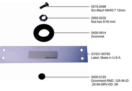
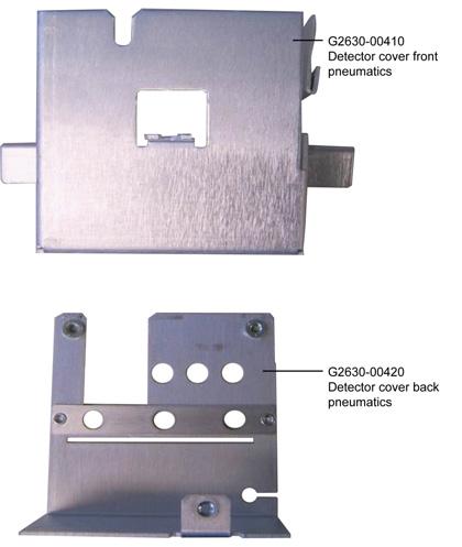
5 Installing a Flame Ionization Detector on an Agilent 6850 Gas Chromatograph These instructions are divided into three parts: Part 1 to prepare the Electronic Pressure Control ("EPC") module for later installation into the Agilent 6850 Gas Chromatograph ("GC") Part 2 to prepare the FID Signal board for later installation Part 3 to perform the actual Accessory installation into the GC Part 1: Preparation of the FID EPC module Locate the following item found in your Accessory kit: Covers Kit G consisting of: Qty. Front EPC cover 1 Back EPC cover 1 Hex nuts, 7/16-inch 3 Grommet, 7/16-inch 1 Screw, M4 x12 mm, pan head 3 Copyright 2007 Agilent Technologies Printed in USA Feb 2007 Agilent Part No. G
6 2

7 Caution Some of these assemblies contain printed circuit boards so standard ESD precautions must be followed: use a static control wrist strap (supplied) connected to a suitable ground in handling the assemblies. The following tools are required for this assembly: Tools Required Torx T-20 driver 7/16-inch open end wrench or nut driver Procedure 1. Prepare a suitable clean, dry, static-free work area. 2. Place the detector system assembly such that its EPC module is centered in your work area with its tubes oriented away from you and its ribbon cable extending to the right. 3. Remove dust caps from the gas connection fittings. 3

8 4. Install the back cover onto the three gas fittings making sure the label passes through slot provided. Loosely secure the cover using 7/16-inch hex nuts, one onto each fitting. 5. Reorient the module such that the ribbon cable is upwards and gas fittings are to the left. 6. Fold the cable first to the left and gently crease it at the PC board to maintain the direction. Then fold the cable back on itself to the right and make a gentle crease such that the second fold is just inside the justinstalled back cover. 4


9 7. Next, fold and gently crease the cable back on itself again, but at an angle such that it now extends at 90-degrees away from you (in the direction of tubing from the module). 5
10 If correctly done, the cable and its folds will be entirely within the body of the module, and the free end of the cable and its connector will extend from the module in the direction of the tubing. 8. Fit the front cover onto the previously-installed back cover, securing it loosely using three screws provided, two in the gas fittings side and one in the PC board side. Make sure the ribbon cable and its connector exit through the slot provided. 6


11 9. Finally, firmly secure all cover screws and hex nuts on the gas connection fittings. Then replace protective dust caps onto the gas connection fittings to maintain cleanliness. 7


12 This completes EPC module preparation for this Accessory. Part 2: Preparation of the FID Signal Board Locate the FID Signal board. Procedure Using a small, sharp pair of diagonal wire cutters, remove and discard the small bracket from the location shown: This completes preparation of the FID Signal board. 8
13 Part 3: Installation of the FID Accessory This kit contains: Kit G Qty. Flame ionization detector system 1 Performance evaluation sample kit 1 Nut warmer cup assembly 1 Nut warmer insulation 1 Wrist strap, disposable, large 1 Screw, M4 x12 mm, pan head 3 Installation sheet (this document) 1 9
 Screws Flow module cable Flow module FID signal board Tools Required Torx T-20 driver Flat blade")
14 The FID detector assembly is a factory-assembled, tested, and calibrated unit. Disassembly of the unit is not required for installation. Ribbon cable Heater/sensor cable FID assembly Ignitor cable Nutwarmer Insulation (3 pieces) Screws Flow module cable Flow module FID signal board Tools Required Torx T-20 driver Flat blade screwdriver Open end wrenches Safety Information Before continuing, read the safety information on your Agilent 6850 Gas Chromatograph User Information CD-ROM. 10
15 BNC BNC To Base - T To Base - T Local Talk Local Talk Installing a Flame Ionization Detector on an Agilent 6850 Gas Chromatograph Prepare for Installation WARNING Hydrogen gas is flammable and potentially explosive. Before replacing the manifold, turn off the hydrogen gas at the source. WARNING Before proceeding, turn off the oven and any heated zones and let them cool down. Turn off all detector gases at their supply, then turn off the main power switch and unplug the power cord. 10. Open the lid. If a column is installed, disconnect it at the detector end. Remove the nut warmer, insulation, and capillary adapter, if present. Close the lid. 11. Turn all gases off at their sources. Disconnect the carrier and detector gas tubing from the back panel of the instrument. Disconnect gas supply tubing from these fittings 11
16 Remove the Lid Top Cover Remove vent tubing, if present Lid top cover, without valve box accessory Remove T-20 Torx screws (8 places) Remove detector cover, if desired Remove the lid top cover. Disconnect the Heater/Sensor Cable 1. Trace the detector heater/sensor cable to the wiring harness near the injection part cooling fan. 2. Disconnect the cable at the connector. Raise the Lid to the Service Position 1. Open the lid. Locate the counterbalance cam in the left rear corner under the lid. Loosen the screw on the right side of the cam. This allows the stop plate to drop down. 12

17 Cam follower Stop plate Screw Counterbalance cam 2. Raise the lid until it is stopped by the safety cable. 3. Raise the stop plate and tighten the screw to lock the lid in the upright service position. WARNING The lid is heavy. Always lock the lid when it is in the service position. 13

18 Remove the Detector Electronics Cover 1. Loosen the two bottom screws on the detector electronics cover. Remove screw Detector electronics cover Loosen screws 2. Remove the top screw on the cover. 3. Lift and remove the detector electronics cover. 14

19 4. Loosen the signal board clamp. Ribbon cable Signal board (FID shown) Signal board clamp 5. Unplug the signal board from the A/D converter board. 6. Disconnect the wiring from the signal board. A/D converter board FID Disconnect the ribbon cable. Unplug the ignitor cable. Pass both cables through the hole to the top side of the lid. The ribbon cable connector will not pass through the rubber grommet in the hole. Use a small screwdriver to push the grommet to the top of the lid. The cables will now fit through the hole. 15

20 Ribbon cable connector Ignitor cable connector TCD Unplug the two-wire switching valve cable at the connector. To release the PRT and filament wires, press down on the orange tabs. Pass the disconnected wires through the hole to the top side of the lid. Switching valve cable connector PRT wires Filament wires 7. Lower the stop plate on the lid cam. Pull the lid forward until the cam follower rests on the curved surface of the cam. Leave the stop plate in the "down" position. 8. Close the lid. 16
 Gas manifold (FID shown) Manifold mounting screws Gas fittings 2. Disconnect the gas fittings.")
21 Remove the Existing Detector and Flow Manifold 1. On the top of the lid, loosen the connector cover plate screws and remove the plates. Cover plate screws (4) Gas manifold (FID shown) Manifold mounting screws Gas fittings 2. Disconnect the gas fittings. The figure shows the FID manifold; the TCD manifold is similar but has only one gas connection. 3. Trace the ribbon cable from the flow manifold and disconnect it from the harness. 4. Remove the three manifold mounting screws. 5. Remove the screws holding the detector assembly in place. 17


22 FID Remove four mounting screws. Mounting screws (one concealed) TCD Remove two mounting screws. Mounting screws 6. Lift the detector and flow manifold out of the lid as a unit. WARNING The fibrous insulation material can cause irritation to the skin, eyes, and mucous membranes. Always wear gloves when working with the insulation. If the insulation is flaky/crumbly, wear protective eyewear and respirator. 7. Remove any insulation that may be in the hole under the detector. 18
 2.")

23 Install the Flame Ionization Detector and Flow Manifold 1. Place the flame ionization detector and flow manifold in position in the lid. Check that no wiring or tubing is trapped under either assembly. Ignitor cable Heater/sensor cable connection Screws (4 places, one not visible) 2. Secure the detector assembly to the lid with four screws. 3. Secure the manifold to the lid with three screws. 4. Plug the manifold ribbon cable into its connector. 5. Install the two connector cover plates. 6. Connect the gas supply lines as shown below. If the previous detector was a TCD, the A and H lines should be folded up in the space under the fittings. Unfold them, being careful to avoid kinks, and feed them up to the manifold area. Connect the line marked A here Connect the line marked M here Connect the line marked H here 19
24 Connect the Heater/Sensor Cable Connect the detector heater/sensor cable to the wiring harness near the injection part cooling fan. Connect the other Leads and the Signal Board 1. Raise the lid to the service position and lock it in place by raising the stop plate. 2. There is an oblong hole through the lid near the left rear corner of the FID assembly. If there is a grommet in the hole, remove it. Pass the ignitor cable and the ribbon cable through the hole into the signal board space. 3. Use a small screwdriver to install the grommet around the cables in the oblong hole. 4. Connect the ribbon and ignitor cables to the signal board. Ribbon cable connector A/D converter board connector Ignitor connector 5. Turn the signal board over, plug it into the A/D converter board, and secure it with the signal board clamp. 6. Install the detector electronics cover and tighten all three screws. 7. Lower the stop plate on the lid cam. Pull the lid forward until the cam follower rests on the curved surface of the cam. Raise the stop plate behind the cam follower and tighten the screw. 8. Close the lid. Be sure that the folded gas lines do not interfere with it. 20
25 9. Install the lid top cover. Finishing Up 1. Install the capillary adapter, if used. 2. Restore the column connection. 3. Restore carrier and other gases to the instrument. 4. Restore power. 5. Apply your normal operating pressures. Leak-check the manifold, back panel, and column fittings. 21
26 22
27
28 Printed on recycled paper. This product is recyclable. Agilent Technologies, Inc. Printed in USA April 2007
Installation Guide. Thermal Conductivity Detector on a 6850 GC Accessory G2623A
 Installation Guide Thermal Conductivity Detector on a 6850 GC Accessory G2623A 2 Agilent Technologies 2007 All Rights Reserved. Reproduction, adaptation, or translation without permission is prohibited,
Installation Guide NPD/ECD Chemical Filters Accessory 19199N
 Installation Guide NPD/ECD Chemical Filters Accessory 19199N Agilent Technologies 2000 All Rights Reserved. Reproduction, adaptation, or translation without permission is prohibited, except as allowed
Installation Guide. Flame Ionization Detector on a 6890 GC. Accessories G1561A, G1562A, G1591A, G1598A
 Installation Guide Flame Ionization Detector on a 6890 GC Accessories G1561A, G1562A, G1591A, G1598A Agilent Technologies 2001 All Rights Reserved. Reproduction, adaptation, or translation without permission
Installation Guide. Purged Packed Inlet, Electronic Pneumatics Control on 6890 GC Accessory G1551A
 Installation Guide Purged Packed Inlet, Electronic Pneumatics Control on 6890 GC Accessory G1551A Agilent Technologies 2001 All Rights Reserved. Reproduction, adaptation, or translation without permission
Installing a Purged Packed (PP) Inlet
 Inlet") Installing a Purged Packed (PP) Inlet Agilent 6850 Gas Chromatograph Accessory G2651A These instructions are divided into two parts: Part 1 to prepare the Electronic Pressure Control ("EPC") module for
Installing a Purged Packed (PP) Inlet Agilent 6850 Gas Chromatograph Accessory G2651A These instructions are divided into two parts: Part 1 to prepare the Electronic Pressure Control ("EPC") module for
Installation Guide Thermal Conductivity Detector Accessory 19232E
 Installation Guide Thermal Conductivity Detector Accessory 19232E Agilent Technologies 2000 All Rights Reserved. Reproduction, adaptation, or translation without permission is prohibited, except as allowed
Installation Guide. Heater Interface Cable for Mass Sensitive Detector Accessory G1590A
 Installation Guide Heater Interface Cable for Mass Sensitive Detector Accessory G1590A Agilent Technologies, Inc. 2001 All Rights Reserved. Reproduction, adaptation, or translation without permission is
Installation Guide. Nitrogen-Phosphorus Detector on 6890 GC Accessories G1575A, G1576A, G1594A, G1599A
 Installation Guide Nitrogen-Phosphorus Detector on 6890 GC Accessories G1575A, G1576A, G1594A, G1599A Agilent Technologies 2001 All Rights Reserved. Reproduction, adaptation, or translation without permission
Installation Guide. Auxiliary Pressure Control Manifold on 6890 GC Accessory G1570A
 Installation Guide Auxiliary Pressure Control Manifold on 6890 GC Accessory G1570A Agilent Technologies 2001 All Rights Reserved. Reproduction, adaptation, or translation without permission is prohibited,
Installation Guide. Volatiles Interface for 6890 Gas Chromatograph Accessory G2319A
 Guide Volatiles Interface for 6890 Gas Chromatograph Accessory G2319A Agilent Technologies, Inc. 2001 All Rights Reserved. Reproduction, adaptation, or translation without permission is prohibited, except
Nickel Catalyst Tube Accessory 19205A
 Installation and Operating Guide Nickel Catalyst Tube Accessory 19205A Agilent Technologies 2000 All Rights Reserved. Reproduction, adaptation, or translation without permission is prohibited, except as
Installing a PTV Inlet
 Agilent 6850 Series II Network GC System Accessories G3345B (Septumless) and G3346B (Septum) These instructions are divided into two parts: Part 1 to prepare the Electronic Pressure Control ("EPC") module
Installing a Purged Packed Inlet
 Installing a Purged Packed Inlet Agilent 6850 Gas Chromatograph This kit contains: Accessory G2651A Description Purged packed column inlet system 1 Top block insulation 1 Bottom block insulation 1 Insulation
Installing an Auxiliary Pressure Control Module
 Installing an Auxiliary Pressure Control Module Agilent 6850 GCs Accessory G3349B These instructions are divided into two parts: Part 1 to prepare the Auxiliary Electronic Pressure Control ("AuxEPC") module
Installing a PTV Inlet
 Agilent 6850 Series II Network GC System Accessories G3345B (Septumless) and G3346B (Septum) There are kits for installing both septum and septumless PTV inlets. This document describes both installations.
Installing a Cool On-Column Inlet
 Agilent 6850 Series II Network GC System Accessory G3344B This kit contains: Description Quantity Machine screws, M4 x 0.7 12 mm 6 Cable ties,.062.625 diameter 6 Ship kit* 1 T-20 Torx screw, M4 x 8 mm
Installing the Flame Ionization Detector EPC Flow Control Manifold
 Installing the Flame Ionization Detector EPC Flow Control Manifold The FID EPC Flow Control Manifold kit can be used to replace any HP 6890 Series FID EPC flow control manifold. This kit contains: Kit
Installing an Auxiliary Pressure Control Module
 Installing an Auxiliary Pressure Control Module Agilent 6850 GCs Accessory G3349B This kit contains: Description Quantity Cable tie.062-.625 diameter 2 Hex nut w/lockwasher 1 Disposable wrist strap 1 Minifold
Installing the CO 2 Cryogenic Oven Cooling Kit
 Installing the CO 2 Cryogenic Oven Cooling Kit Agilent 6850 Series II Network GC System Accessory G2625B This kit contains: Description Chassis 1 Chassis Cover 1 Ship kit: 1 Cooling coil 1 Coil bracket
Agilent G1554A On-Column Capillary Inlet with EPC
 Agilent G1554A On-Column Capillary Inlet with EPC 6890 Gas Chromatograph Installation Guide Agilent Technologies Notices Agilent Technologies, Inc. 2002 No part of this manual may be reproduced in any
Nickel Catalyst Tube on a 6820 GC, Accessory G4318A
 Nickel Catalyst Tube on a 6820 GC, Accessory G4318A Installation Guide The Nickel Catalyst tube (NCT) is used with the 6820 Gas Chromatograph (GC) for trace analysis of CO and CO 2 using a Flame Ionization
Installing the G2743A/G2745A Valve Actuator Kits
 Installing the G2743A/G2745A Valve Actuator Kits sa This document describes the installation of a valve actuator on the 4890 Series, 5890 Series, and 6890 Series Gas Chromatographs (GC). The kits contain:
Agilent G2738A Upstream Capillary Interface
 Agilent G2738A Upstream Capillary Interface 4890, 5890, and 6890 Gas Chromatographs Installation Guide Agilent Technologies Notices Agilent Technologies, Inc. 2003 No part of this manual may be reproduced
Valve Box and Valve Accessories G4315A, G4316A, G4317A
 Valve Box and Valve Accessories G4315A, G4316A, G4317A Installation Guide The G4315A, G4316A, and G4317A accessories consist of separate kits depending on the custom configuration ordered. These kits may
Agilent G3969A Transfer Line Interface for an Agilent 7697A HS Accessory
 Agilent G3969A Transfer Line Interface for an Agilent 7697A HS Accessory For the Agilent Intuvo 9000 Gas Chromatograph Installation Instructions Parts Supplied Table 1 Parts supplied with an Agilent G3969A
Agilent G3510A/G3511A Multimode Inlet
 For the Agilent 7890A Gas Chromatograph Installation Instructions Parts Supplied Table Liquid Carbon Dioxide (CO 2 ) Kit G350A Description Liquid CO2 MMI inlet assembly (MMI Inlet weldment assembly, EPC
Installing the 6850 Direct Valve Column Connector Kit
 Use this kit to bypass the inlet and connect your 6850 gas or liquid sampling valve directly to a column. To use this kit, your 6850 GC must have a purged packed inlet. This kit contains: Installing the
Agilent G3348B Flame Photometric Detector
 Agilent G3348B Flame Photometric Detector For Agilent 6850 GC Installation and Operation Agilent Technologies Notices Agilent Technologies, Inc. 2005 No part of this manual may be reproduced in any form
Installation Guide. Agilent 7683 Automatic Liquid Sampler
 Agilent 7683 Automatic Liquid Sampler Agilent Technologies 1997 2001 All Rights Reserved. Reproduction, adaptation, or translation without permission is prohibited, except as allowed under the copyright
HP 6890Series Gas Chromatograph. Installation Guide. Flame Ionization Detector. Accessories HP G1561A HP G1562A HP G1591A HP G1598A
 HP 6890Series Gas Chromatograph Installation Guide Flame Ionization Detector Accessories HP G1561A HP G1562A HP G1591A HP G1598A DHewlett-Packard Company 19891995 All Rights Reserved. Reproduction, adaptation,
29 Installation Step 1. Unpacking the GC Cable diagrams Step 2. Placing the GC system on the benchtop Step 3. Turning the power on
 29 Installation Step 1. Unpacking the GC Step 2. Placing the GC system on the benchtop Step 3. Turning the power on Step 4. Connecting tubing to the gas supply tank Step 5. Attaching traps to the gas supply
A g i l e n t A G a s C h r o m a t o g r a p h Service Manual
 A g i l e n t 7 8 2 0 A G a s C h r o m a t o g r a p h Service Manual Notices Agilent Technologies, Inc. 2012 No part of this manual may be reproduced in any form or by any means (including electronic
Deans Switch Microfluidics
 TRACE 1300 and TRACE 1310 Gas Chromatographs Deans Switch Microfluidics Installation Guide 31709740 Revision A June 2014 2014 Thermo Fisher Scientific Inc. All rights reserved. TRACE 1300, and TRACE 1310
Agilent 6890 Gas Chromatograph
 Agilent 6890 Gas Chromatograph Maintaining Your GC Agilent Technologies Notices Agilent Technologies, Inc. 2007 No part of this manual may be reproduced in any form or by any means (including electronic
Agilent 210/218 - Isocratic Pump
 Agilent 210/218 - Isocratic Pump Installation of the Stainless Steel Tubing Kit Introduction This technical note shows you how to install the Stainless Steel Tubing Kit for the isocratic pump of the Agilent
DISPLACEMENT PUMP INSTRUCTIONS-PARTS LIST Rev. K. Model , Series A Model , Series B Model , Series A
 INSTRUCTIONS-PARTS LIST INSTRUCTIONS This manual contains important warnings and information. READ AND KEEP FOR REFERENCE. DISPLACEMENT PUMP 308190 Rev. K 3000 psi (210 bar) MAXIMUM WORKING PRESSURE Model
Alcatel-Lucent 7310 DC Metro Cell AWS (B4) Kit MC-DBR1, MC-DBR2, MC-DBR3, MC-DBR4, MC-DBR5. Installation Manual
 Kit MC-DBR1, MC-DBR2, MC-DBR3, MC-DBR4, MC-DBR5. Installation Manual") Alcatel-Lucent 7310 DC Metro Cell AWS (B4) Kit MC-DBR1, MC-DBR2, MC-DBR3, MC-DBR4, MC-DBR5 Installation Manual ALCATEL-LUCENT DC METRO CELL AWS (B4) KIT INSTALLATION INSTRUCTIONS Document Information Identification
Alcatel-Lucent 7310 DC Metro Cell AWS (B4) Kit MC-DBR1, MC-DBR2, MC-DBR3, MC-DBR4, MC-DBR5 Installation Manual ALCATEL-LUCENT DC METRO CELL AWS (B4) KIT INSTALLATION INSTRUCTIONS Document Information Identification
Agilent 490 Micro GC Internal and External Mount Genie Filter Brackets
 Agilent 490 Micro GC Internal and External Mount Genie Filter Brackets Installation The Genie Filter Bracket kits include mounting hardware to install a sample line filter on an Agilent 490 Micro GC. Agilent
SOS SERIES SOS1 SOS2. Spares On Site Battery Cabinet Installation Guide rEV3
 Atlantic Battery Systems 1065 Market Street Paterson, NJ 07513 Phone: (800) 875-0073 Fax: (973) 523-2344 sales@atbatsys.com www.atbatsys.com SOS1 SOS2 SOS SERIES Spares On Site Battery Cabinet Installation
Installation Instructions
 010A00 011A00 014A00 SMALL ROOFTOP UNITS TWO POSITION OUTDOOR AIR DAMPER 2to15TONS (50/60 Hz) Installation Instructions TABLE OF CONTENTS PACKAGE CONTENTS... 1 PACKAGE USAGE... 1 SAFETY CONSIDERATIONS...
Agilent G2647A (Single) and G2648A (Dual) Flame Photometric Detector Update Kits
 and G2648A (Dual) Flame Photometric Detector Update Kits") Agilent G2647A (Single) and G2648A (Dual) Flame Photometric Detector Update Kits For Agilent 6850 and 6890 GCs Update, Operation and Maintenance Agilent Technologies Notices Agilent Technologies, Inc.
Agilent G2647A (Single) and G2648A (Dual) Flame Photometric Detector Update Kits For Agilent 6850 and 6890 GCs Update, Operation and Maintenance Agilent Technologies Notices Agilent Technologies, Inc.
INSTALLATION INSTRUCTIONS
 INSTALLATION INSTRUCTIONS Accessory Application Publications No. SYSTEM 2005 ACCORD All 27511 (DX, LX) 2-AND 4-DOOR Issue Date AUG 2004 PARTS LIST Security System Attachment (LX): P/N 08E55-SDA-100A Unit
Altivar 61/71 Adjustable Speed Drives Plastic Kits and Power Terminal Kit
 Altivar 61/71 Adjustable Speed Drives Plastic Kits and Power Terminal Kit Instruction Bulletin 30072-453-27 Retain for future use. For Frame Sizes 2 5: ATV61H075M3, -HU15M3, -HU22M3, -HU30M3, -HU40M3,
Agilent G2333B (Single) and G2334B (Dual) Flame Photometric Detectors
 and G2334B (Dual) Flame Photometric Detectors") Agilent G2333B (Single) and G2334B (Dual) Flame Photometric Detectors For Agilent 6890 GC Installation and Operation Agilent Technologies Notices Agilent Technologies, Inc.2004, 2005 No part of this manual
Agilent G2333B (Single) and G2334B (Dual) Flame Photometric Detectors For Agilent 6890 GC Installation and Operation Agilent Technologies Notices Agilent Technologies, Inc.2004, 2005 No part of this manual
CAUTION The sensor must always be completely filled with process media in order to measure accurately.
 SITRANS F Coriolis Flowmeters Quick Start Before installing, including in hazardous areas, refer to the Operating Instructions on the internet or on the SITRANS F literature CD-ROM. They contain detailed
If there is additional labor or other costs above the 4 hrs labor you must call VMAC for approved coverage
 Installation Manual for the A500027 RAPTAIR MF Dual Air Filter Retrofit Kit Author: Brian Collings Date: 15/07/2014 1900997 - Manual, Installation (A500027) Systems or Parts Affected: D600005BETA01-D600005BETA59
Installation Instructions. PowerFlex 700 Drive - Frame 8 Components Replacement
 Installation Instructions PowerFlex 700 Drive - Frame 8 Components Replacement Important User Information Solid-state equipment has operational characteristics differing from those of electromechanical
In addition to this instruction sheet, the following are included in this kit (some additional parts are included for future maintenance):
:") Instruction Sheet 62068-89 Overview The components in this kit directly replace components in the existing analyzer. Some of these components have safety and/or electrostatic discharge considerations associated
Instruction Sheet 62068-89 Overview The components in this kit directly replace components in the existing analyzer. Some of these components have safety and/or electrostatic discharge considerations associated
Replacing the Batteries in the Fortress LI 660
 Replacing the Batteries in the Fortress LI 660 This FTS describes how to replace the batteries in Fortress LI 660 units. Batteries should be replaced by a qualified technician. If you have any questions
ROUSH Active IO Exhaust. Installation Instructions P/N: (R LITE) Fastback GT Convertible GT V8
 Fastback GT Convertible GT V8") Installation Instructions P/N: 422128 (R1318-5231LITE) Fastback GT Convertible GT V8 39555 Schoolcraft Rd, Plymouth MI, 48170 800.59.ROUSH ROUSH Active IO Exhaust Installation Instructions P/N: 422128
Installation Instructions P/N: 422128 (R1318-5231LITE) Fastback GT Convertible GT V8 39555 Schoolcraft Rd, Plymouth MI, 48170 800.59.ROUSH ROUSH Active IO Exhaust Installation Instructions P/N: 422128
Agilent 210/218 - Binary Pump
 Agilent 210/218 - Binary Pump Installation of the Stainless Steel Tubing Kit Introduction This technical note shows you how to install the Stainless Steel Tubing Kit for the binary pump of the Agilent
Prodigy HDLV Generation II Pump Panel
 Prodigy HDLV Generation II Pump Panel Customer Product Manual Issued 01/10 For parts and technical support, call the Finishing Customer Support Center at (800) 433-9319. This document is subject to change
SITRANS F Coriolis Flowmeters SITRANS FCS400 sensor Quick Start
 SITRANS F Coriolis Flowmeters Quick Start Before installing, including in hazardous areas, refer to the Operating Instructions on the internet or on the SITRANS F documentation CD-ROM which is included
Electrically Held to Mechanically Latched Contactor
 Electrically Held to Mechanically Latched Contactor Bulletin 1502 Series E or later Retrofit Instructions Important User Information Read this document and the documents listed in the Additional Resources
Customer Information. Service Engineer s Responsibilities. Additional Instruction Notes GC Preventive Maintenance Checklist Standard
 Agilent Preventive Maintenance provides factory recommended service for your analytical systems to assure reliable operation and the accuracy of your results. Delivered by highly-trained and certified
Replacing the Battery in the Patriot SPS 250, SPS 300 and SPS 450
 Replacing the Battery in the Patriot SPS 250, SPS 300 and SPS 450 PAT 609 P February 1, 1993 This PAT describes how to replace the battery in Patriot SPS 250, SPS 300, and SPS 450 units. Replacing the
5000TOC Sensor Service Manual
 Part No. 84449 5000TOC Sensor Service Manual This document contains proprietary information, which is protected by copyright. All rights are reserved. No part of this document may be photocopied (other
Model 4430 Photoionization Detector (PID) Operator s Manual
 Operator s Manual") Model 4430 Photoionization Detector (PID) Operator s Manual 151 Graham Road P.O. Box 9010 College Station, Texas 77842-9010 Telephone (979) 690-1711 FAX (979) 690-0440 www.oico.com oimail@oico.com Notice
Model 4430 Photoionization Detector (PID) Operator s Manual 151 Graham Road P.O. Box 9010 College Station, Texas 77842-9010 Telephone (979) 690-1711 FAX (979) 690-0440 www.oico.com oimail@oico.com Notice
Switching DC Power Supply
 99 Washington Street Melrose, MA 02176 Phone 781-665-1400 Toll Free 1-800-517-8431 Visit us at www.testequipmentdepot.com Model 1693, 1694 Switching DC Power Supply INSTRUCTION MANUAL 1 Safety Summary
Agilent SD-1 Purification System ml/min
 Agilent SD-1 Purification System - 200 ml/min Introduction Installation of the Capillary Kit This technical note shows you how to install the Stainless Steel Capillary Kit (SD- 1 Purification System -
MK7 GTI Electronic Folding Mirror Conversion
 MK7 GTI Electronic Folding Mirror Conversion 01 Mirror and Switch Installation 1. Using a soft pry tool remove the trim panel on the driver side door handle. 02 2. Remove 2 T-30 torx screws. 03 3. On the
Instruction Manual. Labnet Spectrafuge 16M Microcentrifuge
 Instruction Manual Labnet Spectrafuge 16M Microcentrifuge Labnet International PO Box 841 Woodbridge, NJ 07095 Phone: 732 417-0700 Fax: 732 417-1750 email: labnet@labnetlink.com Safety Precautions NEVER
SITRANS F. Ultrasonic Flowmeters. Hi-Precision Mounts. Operating Instructions. Answers for industry.
 SITRANS F Ultrasonic Flowmeters Hi-Precision Mounts Operating Instructions Edition 12/2014 Answers for industry. Preliminary Instructions 1 Reflect Mount Mode 2 SITRANS F Ultrasonic Flowmeters Hi-Precision
ES25 Battery-powered ACSR Cutter with 120 V Charger with 220 V Charger
 INSTRUCTION MANUAL ES25 Battery-powered ACSR Cutter 22131 with 120 V Charger 22132 with 220 V Charger Read and understand all of the instructions and safety information in this manual before operating
Catalyser Introduction. 3. Hazard Information. 2. Area of Application. 3.1 Symbology
 ENGLISCH Catalyser 2300-0001 1. Introduction We are pleased with your decision to purchase the Catalyser. Please read the following operating instructions carefully and observe the safety information they
18SP653 EPA04 and EPA98 MBE 4000 High Pressure Fuel Line and Transfer Tube Installation
 18SP653 EPA04 and EPA98 MBE 4000 High Pressure Fuel Line and Transfer Tube Installation KIT DESCRIPTION A service kit (P/N: A4600700135) is now available to install EPA07 high pressure fuel injector lines
N-084M and N-069M-DV Series Heat Exchanger Replacement
 N-084M and N-069M-DV Series Heat Exchanger Replacement Models Include: N-069M-DV, N-084M, N-084M-DV N-084M-ASME, N-084M-DV-ASME This instructional manual is only intended for use by a qualified service
Customer Information. Service Engineer s Responsibilities. Additional Instruction Notes GC Preventive Maintenance Checklist Standard
 7890 GC Standard Agilent Preventive Maintenance provides factory recommended service for your analytical systems to assure reliable operation and the accuracy of your results. Delivered by highly-trained
FlexJet Carriage Circuit Board (PCB) Replacement
 Replacement") P/N: 111484 R0 14140 NE 200th St. Woodinville, WA. 98072 PH: (425) 398-8282 FX: (425) 398-8383 ioline.com FlexJet Carriage Circuit Board (PCB) Replacement Notices: Warning! Ensure that all AC power cables
P/N: 111484 R0 14140 NE 200th St. Woodinville, WA. 98072 PH: (425) 398-8282 FX: (425) 398-8383 ioline.com FlexJet Carriage Circuit Board (PCB) Replacement Notices: Warning! Ensure that all AC power cables
260 Solvent Vapor Exit Accessory
 Theory of operation The Solvent Vapor Exit (SVE) is a GC accessory for performing large volume injections with a Cool On-Column inlet (COC). At the start of the run, the SVE solenoid valve is open as the
Upgrading the Sure Coat Modular Gun Control System
 Instruction Sheet P/N 007365B Upgrading the Sure Coat Modular Gun Control System WARNING: Read the Safety section in the Sure Coat Modular Gun Control System manual before performing any of the following
Users Manual. Accessories Motor and Phase Rotation Indicator ships with the following items: 3 test leads 3 test probes 3 alligator clips 9 V battery
 MS5900 Users Manual Table of Contents Introduction Motor and Phase Rotation Indicator is a handheld, battery-operated instrument designed to detect the rotary field of three-phase systems and determine
Altivar 61/71 Adjustable Speed Drives Spare Parts Kits
 Altivar 61/71 Adjustable Speed Drives Spare Parts Kits Instruction Bulletin 30072-452-77 Retain for future use. For Frame Size 10: ATV61HD90M3X, ATV61HC13N4, ATV71HD75M3X, ATV71HC11N4 30072-452-77 Spare
BATTERY REPLACEMENT GUIDE
 BATTERY REPLACEMENT GUIDE Uninterruptible Power Supply Models: SG2K-1T, SG2K-2T FALCONElectric Inc., 5116 Azusa Canyon Rd., Irwindale, California 91706, (626) 962-7770, Fax 626-962-7720, Email: sales@falconups.com
NPD to FID conversion on SRI 8610C or 310C GC July2012
 July2012 Unplug GC from wall power The SRI 8610C GC is shown at right. The NPD detector will be located at the right side of the column oven covered with an insulated aluminum box. Remove the single screw
Mustang V-6 Cold Air Intake P/N: ( A600) Application: Ford Mustang 3.7L Manual or Automatic Transmission
 Application: Ford Mustang 3.7L Manual or Automatic Transmission") 2015-2017 Mustang V-6 Cold Air Intake P/N: 421828 (131537-9A600) Application: 2015-2017 Ford Mustang 3.7L Manual or Automatic Transmission Installation Instructions Before installing your ROUSH Performance
2015-2017 Mustang V-6 Cold Air Intake P/N: 421828 (131537-9A600) Application: 2015-2017 Ford Mustang 3.7L Manual or Automatic Transmission Installation Instructions Before installing your ROUSH Performance
190M. Medical ScopeMeter. Safety Information
 190M Medical ScopeMeter PN 4202934 June 2012, Rev. 1 2012 Fluke Corporation. All rights reserved. Printed in Romania. All product names are trademarks of their respective companies. WX Warning To prevent
RT Series Step Down Transformer for RT Series UPS 6-10kVA UL Input Vac Output Vac User Guide
 RT Series Step Down Transformer for RT Series UPS 6-10kVA UL Input 208-240 Vac Output 208-120 Vac User Guide UNLESS SPECIFICALLY AGREED TO IN WRITING, SELLER (A) MAKES NO WARRANTY AS TO THE ACCURACY, SUFFICIENCY
Battery Replacement. Installation Instructions. Summary of Changes. Catalog Number 2711P-RY2032. Original Instructions
 Installation Instructions Original Instructions Battery Replacement Catalog Number 2711P-RY2032 Topic Page Summary of Changes 1 Important User Information 2 Precautions 3 About This Publication 2 Replace
For more information about Agilent Technologies services please visit our web site using the following URL
 Agilent Preventive Maintenance provides factory recommended service for your analytical systems to assure reliable operation and the accuracy of your results. Delivered by highly-trained and certified
Feeder Circuit Breaker Units Secure Support Pan and Change Door Latch
 Installation Instructions Feeder Circuit Breaker Units Secure Support Pan and Change Door Latch Catalog Numbers 2193FZ Topic Page About This Publication 1 Required Tools 1 Important User Information 2
System 3 ZB1PS Device Chassis. Operator s Manual
 System 3 ZB1PS Device Chassis Operator s Manual System 3 ZB1PS Operator's Manual Copyright 2007 Tucker-Davis Technologies, Inc. (TDT). All rights reserved. No part of this manual may be reproduced or transmitted
Model Fixed Rack-Mount Kit
 Model 4299-7 Fixed Rack-Mount Kit Keithley Instruments 28775 Aurora Road Cleveland, Ohio 44139 1-800-935-5595 tek.com/keithley Assembly and Mounting Instructions Introduction This document contains the
HOYMILES MICRO-IVERTER MI-250
 HOYMILES MICRO-IVERTER MI-250 TECHNICAL MANUAL CONTENTS INTRODUCTION... 3 SAFETY... 4 SYMBOL ILLUSTRATION... 4 INSTALLATION WARNINGS... 5 PREPARE FOR INSTALLING... 6 TRANSPORT AND INSPECT... 6 CHECK INSTALLATION
M-9603-SVT mm Cold Air Kit w/premium Calibration INSTALLATION INSTRUCTIONS
 Please visit www.fordracingparts.com for the most current instruction information!!! PLEASE READ ALL OF THE FOLLOWING INSTRUCTIONS CAREFULLY PRIOR TO INSTALLATION. AT ANY TIME YOU DO NOT UNDERSTAND THE
Ford 7.3L SuperDuty Cold Air Intake
 999.5-2003 Ford 7.3L SuperDuty Cold Air Intake ! DISCLAIMER ) By installing this product onto your vehicle, you assume all risk and liability associated with its use. 2) It is your responsibility to make
Installation instructions
 Installation instructions Akrapovič Exhaust System: Optional Wireless Kit for the Porsche 911 Carrera (type 991) Porsche 911 Carrera S (type 991) Porsche 911 Carrera 4 (type 991) Porsche 911 Carrera 4S
Pump Sentry. Models 812 PS & 1612 PS INSTALLATION INSTRUCTIONS
 Pump Sentry Models 812 PS & 1612 PS INSTALLATION INSTRUCTIONS The Pump Sentry is an innovative power station designed to operate your pump during a power outage. When properly installed, it will provide
S4M Pulley and Gears Maintenance Kit
 S4M Pulley and Gears Maintenance Kit Installation Instructions This kit includes the parts and documentation necessary to install the drive system maintenance kit into the S4M. Read these instructions
BEFORE USING THE PRODUCT
 HL-17015-5 BEFORE USING THE PRODUCT Thank you for purchasing an Oriental Motor product. Please read this BEFORE USING THE PRODUCT and the separate manual entitled OPERATING MANUAL thoroughly to ensure
INSTALLATION & PART S MANUAL
 INSTALLATION & PART S MANUAL CONVERSION KIT 96110119 FOR CONVERTING SNO-WAY S STANDARD LIGHTING KITS (96102357 and 96106606) TO THE EIS KIT Sno-Way, Down Pressure and EIS are registered trademarks of Sno-Way
PET UNIT DOSE CABINET
 PET UNIT DOSE CABINET INSTALLATION MANUAL 244-200 244-205 FN: 08-134 Rev A 11/17 Pet Unit Dose Cabinet This manual covers operation procedures for the following products: 244-200 Cabinet, PET, Unit Dose
Installation Manual. AutoSteer. Gleaner Combine. AutoGuide 2 Steer Ready. Supported Models A66 A76 R66 R76 S67 S77 PN: A
 Installation Manual AutoSteer Gleaner Combine AutoGuide 2 Steer Ready Supported Models A66 A76 R66 R76 S67 S77 PN: 602-0312-01-A LEGAL DISCLAIMER Note: Read and follow ALL Instructions in this manual carefully
SAFETY INSTRUCTIONS Before installation and operation, read these instructions carefully and use this product only in the manner described by the manu
 Installation Manual RANGE HOOD MODEL: BUF-07W BUF-07P BUF-07W/P TABLE OF CONTENTS Safety Instructions... 2, 3 Name of Parts... 4 Circuit Diagram... 4 Dimensions/Accessories... 5, 6 Range Hood Location...
Model TC-20. Tube Cut-Off Machine. Operator s Manual REV H
 Model TC-20 Tube Cut-Off Machine Operator s Manual 90-2333 REV H Scientific Systems, Inc. 349 N. Science Park Road State College, PA 16803 www.ssihplc.com Phone: 800-441-4752 Fax: 814-238-7532 Email: sales@ssihplc.com
INSTALLATION INSTRUCTIONS
 INSTALLATION INSTRUCTIONS Accessory Application Publications No. AII 24664-25319 SYSTEM 2003 CR-V Issue Date MAY 2003 PARTS LIST Security System (sold separately) P/N 08E51-EP4-100 Security System Attachment
ELECRAFT KX3 Application Note
 ELECRAFT KX3 Application Note Installing the Speaker Grille Cloth Revision A, July 30, 2012 Copyright 2012, Elecraft, Inc., All Rights Reserved Background Some KX3 owners have reported issues with the
Installation Note for Solvent Selection Valve Upgrade Kit (G1360A)
") s1 Installation Note for Solvent Selection Valve Upgrade Kit (G1360A) This note describes how to install the solvent selection valve upgrade kit into an Agilent 1100 Series binary pump. General Information
s1 Installation Note for Solvent Selection Valve Upgrade Kit (G1360A) This note describes how to install the solvent selection valve upgrade kit into an Agilent 1100 Series binary pump. General Information
NANOPAC-300 & 500 Power Supply. Instruction manual NANOPAC-300 & NANOPAC-500
 NANOPAC-300 & 500 Power Supply Instruction manual NANOPAC-300 & NANOPAC-500 Version 01C Feb 5th, 2014 1 Packing list NANOPAC-300 or 500-1x NANOPAC-300 Power Supply or NANOPAC-500-1x Power Cord - 1x Instruction
Forbidden Diesel Performance Ford 6.7L Powerstroke EGR Delete Instructions 6.7L EGR DELETE BY FORBIDDEN DIESEL PERFORMANCE. Page 1
 6.7L EGR DELETE BY FORBIDDEN DIESEL PERFORMANCE Page 1 WARNING REGARDING EMISSIONS LAWS Not legal for sale or use on pollution-controlled motor vehicles anywhere in the United States. Legal ONLY for off-road