A g i l e n t A G a s C h r o m a t o g r a p h Service Manual
|
|
|
- Daniella Cooper
- 5 years ago
- Views:
Transcription
1 A g i l e n t A G a s C h r o m a t o g r a p h Service Manual
2 Notices Agilent Technologies, Inc No part of this manual may be reproduced in any form or by any means (including electronic storage and retrieval or translation into a foreign language) without prior agreement and written consent from Agilent Technologies, Inc. as governed by United States and international copyright laws. Manual Part Number G Edition Third edition, August 2012 Printed in China Agilent Technologies (Shanghai) Co., Ltd. 412 Ying Lun Road Waigaoqiao Free Trade Zone Shanghai P.R.China Warranty The material contained in this document is provided as is, and is subject to being changed, without notice, in future editions. Further, to the maximum extent permitted by applicable law, Agilent disclaims all warranties, either express or implied, with regard to this manual and any information contained herein, including but not limited to the implied warranties of merchantability and fitness for a particular purpose. Agilent shall not be liable for errors or for incidental or consequential damages in connection with the furnishing, use, or performance of this document or of any information contained herein. Should Agilent and the user have a separate written agreement with warranty terms covering the material in this document that conflict with these terms, the warranty terms in the separate agreement shall control. Safety Notices A warning calls attention to a condition or possible situation that could cause injury to the user. 2
3 A caution calls attention to a condition or possible situation that could damage or destroy the product or the user's work. Contents Notices 2 1 Before Servicing the Instrument 13 Safety Hand tools Specialized tools Electronic tools Pneumatic tools For Checking Inlet Pressure Inlets Detectors 39 Inlet overview Split/Splitless Inlet Replacing the split/splitless inlet Replacing the split/splitless inlet top weldment assembly Replacing the split/splitless inlet split vent line Replacing the split/splitless inlet split vent filter canister and valve assembly Reinstalling the split/splitless inlet Purged Packed Inlet Replacing the Purged Packed inlet Replacing the Purged Packed inlet heater.. 35 Detector overview... 40
4 About the detector signal boards Accessing detector signal boards Replacing detector signal boards Flame Ionization Detector (FID) Selecting an FID jet Replacing the FID interconnect assembly or spring Replacing the heater Replacing the FID signal board Replacing the electrometer Replacing the glow plug (ignitor) Replacing the entire FID Ultrasonic cleaning the FID Nitrogen Phosphorus Detector (NPD) Selecting an NPD jet Removing the NPD electrometer Replacing the entire NPD Replacing an NPD signal board Replacing the NPD heater Replacing the NPD electrometer Cleaning the NPD jet and collector Cleaning the NPD Thermal Conductivity Detector (TCD) Replacing the TCD detector cell Replacing the TCD switching valve Micro-cell Electron Capture Detector (uecd). 85 Replacing the uecd heater/sensor assembly. 85 Replacing the uecd makeup gas adapter Frequency test Leak test Performing a radioactivity leak test (wipe test) Flame Photometric Detector (FPD) Preparing for maintenance Disassembling the FPD Rebuilding the FPD optics assembly
5 Reassembling the FPD Replacing the FPD Bake out and run checkout test Replacing the heater/sensor assemblies Replacing the FPD signal board EPC modules 125 EPC overview Repairing EPC modules Accessing EPC modules Replacing the EPC modules Replacing EPC module proportional valves Performance Verification 131 About Chromatographic Checkout To Prepare for Chromatographic Checkout To Check FID Performance Typical values To Check NPD Performance Typical values To check TCD Performance To Check uecd Performance Typical values To Check FPD Performance (Sample ) Configuration 157 Configuration overview Inlet example Detector example PCM example Heater assignments
6 GC modules and the communications buss To configure an MSD transfer line To configure a valve box Replacing a GC module Removing a GC module Changing the GC configuration Configuration locks Installing new devices Configuring time External Cabling Internal Cabling 181 Connectors on the back of the GC Remote Start/Stop APG Remote Control Cable pinouts, remote start/stop, general use Cable pinouts, GC to 3395B/3396C Integrator Automatic sampler for GC Analog signal outputs Analog cable: GC to 3395A/B or 3396B/C Integrators and C/D/E Analog to Digital Interface instrument Analog cable: general use Internal cabling overview Ignitor cable, FID NPD power cable AC power inlet assemblies
7 Motor Harness & AC Control Assembly Inlet/Detector heater harness Aux Heater/Valve Box Harness Communications Harness GC/MS Second Inlet Upgrade Harness Keyboard display cable Display Cable Assembly Mainframe 193 Mainframe overview Covers and Fans Removing and replacing the covers Replacing the oven bezel Replacing the inlet cooling fan Replacing the EPC cooling fan Replacing the oven door Oven temperature control Oven temperature troubleshooting Measuring inlet and detector heater and PRT resistance Testing resistance of the oven heater coil. 204 Replacing the oven shroud, oven fan, and oven fan motor Replacing the oven flapper assembly Replacing Components Inside the Electronics Panel Accessing the analog and power board Replacing the ALS board Replacing the fuse on the ALS controller board Removing the valve bracket
8 10 Valves 229 Replacing the logic board Replacing the analog and power board Replacing Components Inside the Lower Rear Metal Cover Replacing the AC board Replacing the oven triac Replacing the power transformer Valves Introduction Valco W-series minivalves Gas sample valves Valve Box Installing the valve box Removing the valve box assembly Actuators Installing the actuators Valve actuator drivers Replacing a solenoid valve (new style) Valve actuator alignment Typical Valve Configurations Custom Plumbing (diagram required), Option Gas Sampling Option, Option 701 or Column Isolation, Option 702 or Two Stream Selection (Requires Gas Sampling), Option 703 or Custom Plumbing (Diagram Required), Option Gas Sampling with Backflush of Precolumn to Vent, Option Gas Sampling with Backflush to Detector, Option Gas Sampling with Sequence Reverse and Backflush of Column 1, Option Troubleshooting
9 Chromatographic symptoms Loss of sensitivity or excessive drift Loss of peaks in specific areas of the chromatogram Extraneous peaks Peak broadening and tailing Baseline shifts Baseline upsets Variation in peak area and retention time 255 Pressure check Electrical 257 Power options Converting the power option Remote start/stop connection Remote control Temperature sensor resistance Ceramic and glass fuses AC power board schematic Oven shroud Firmware 267 Firmware overview Confirm firmware update To Update GC Firmware To Update Frit Constants Service Mode Diagnostics 275 Service mode overview Detector diagnostics Signal board diagnostics
10 Multiplexed ADC Pneumatics Power diagnostics Printed circuit boards 283 AC power board Analog and power board Logic and communications board Keyboard interconnect board FID signal board TCD signal board uecd signal board NPD signal board FID electrometer board uecd electrometer board NPD electrometer board FPD signal board Illustrated Parts Breakdown 297 Overview of the IPB Inlets Split/Splitless Inlet (SSL) Split/Splitless Inlet SSL Split vent trap (7820) Split Splitless Inlet Body Split Splitless Inlet Warmer Consumables and Parts for the Split/Splitless Inlet Purged Packed Inlet (PP) Purged Packed Inlet Upper Body Purged Packed Inlet Consumables and Parts for the Purged Packed Inlet 10
11 Detectors Flame Ionization Detector (FID) FID body FID Collector Assembly FID Base Assembly Consumables for the FID Thermal Conductivity Detector (TCD) Thermal Conductivity Detector (TCD) Consumables for the TCD Microcell Electron Capture Detector (uecd) 331 Microcell Electron Capture Detector (uecd) Consumables for the uecd Nitrogen Phosphorus Detector (NPD) Nitrogen Phosphorus Detector (NPD) Consumables for the NPD Flame Photometric Detector (FPD) FPD inert transfer line parts FPD ignitor and heat shield assembly PMT and bracket assemblies FPD lens assembly FPD Covers Consumables for the FPD EPC modules Nickel catalyst accessory Covers Covers Mainframe Automatic Liquid Sampler Parts Oven Oven assembly Oven flapper assembly Valves Valve box assembly Valve driver assembly Valve actuator assembly (1 of 2) Valve actuator assembly (2 of 2) Valco W-series minivalve Electrical
12 12 Electronics carrier Display and Keyboard AC power components AC circuit board components AC power kits Main transformer Power cords Chassis fans
13 1 Before Servicing the Instrument Safety 13 Hand tools 14 Specialized tools 15 Electronic tools 17 Pneumatic tools 18 13
14 Safety Before servicing the GC, observe the safety precautions in the 7820A Safety Manual. Hand tools We assume you have a well-equipped toolbox, but some of the special tools listed here will be helpful. T-20 Torx Driver T-20 Torx Key (for close-quarters work) T-10 Torx Driver T-10 Torx Key (for close-quarters work) #1 Pozidriv Screwdriver #2 Pozidriv Screwdriver ¼-inch Nut Driver (FID Jets) 7mm Nut Driver Diagonal Cutters Crimper/Wire Strippers Tubing Cutters Restek # Agilent Alternate for Europe: HICHROM Ltd - Part No: HI-196 Description: Tubing Cutters - Price: The Markham Centre Station Road Theale, Berkshire RG7 4PE, UK Telephone: +44 (0) mailto: salesw@hichrom.co.uk 14

15 Specialized tools 15
16 FID Flow Tool FID Cleaning Kit , (.010-inch Guitar String) Injection Port Cleaning Kit Piece File Kit RSF-1200 (Ferrule Removal tool not shown ) Fiberglass Tape Teflon Tape White Gloves NPT Adapter /16-inch by #20 Thread Chaser (Die) to clean 1/8-inch Swagelok threads Other Supplier On/Off Valve 1/8-inch Ball Valve Exacto Knife Metric ( ) and English Allen Wrench Hex Keys Pin Vise and small drill bit Tweezers Micro Probes (Sharp Object) RMP-5005 Qty 5 Inspection Mirror

17 Electronic tools Digital Multimeter (Fluke 110 shown) Power Outlet Test Tool (Radio Shack/Sears/Electrical Supply) Static Strap Various jumpers and clip leads electronic supply Useful Cables not shown: Crossover LAN Cable Pin RS-232 Null Modem Cable G

18 Pneumatic tools Electronic Leak Detector VAC VAC (Agilent) Rotameter Porter Model 65 Tube cc/min He, Tube cc/min Air 18
 adapted with a Headspace Probe")
19 Electronic Flow Meter ADM ADM U (Mass Flow Version) Electronic "Mass" Flow Meter Flow Tracker Model 1000 Flow Only Model 2000 with Leak Detector Universal Power Adapter White Silicone Tubing: 4 meters cm For Checking Inlet Pressure Quality Analog Pressure Gauge (0-100 or 0-60 PSIG) adapted with a Headspace Probe ( HSP) need NPT adapter and TCD Ferrules Set , , Digital Pressure Gauge (0-100 PSIG) Omega Model HHP-201 Adapted with 1/8-inch NPT adapter , SS Capillary , Reducing Ferrule and 530 um Column Ferrule NPD Flow adapter - G


20 G FID/NPD Jet Plug No-Hole Column Ferrules FID Flow adapter


21 uecd/tcd Detector Plug Plastic 1/8-inch Swagelok Cap P/N Qty 3 Replacement Septum Purge Fitting for EPC Module P/N G (Not included in kit) No Hole Column Nut (Use with any ferrule) 21
22
23 2 Inlets Inlet overview 23 Split/Splitless Inlet 24 Purged Packed Inlet 31 23
24 Inlet overview Inlets are a means of introducing a sample into the carrier gas stream and then into the analyzing column. The term "Inlets" includes: Injection ports, for use with a syringe Sampling valves for high sample size reproducibility Split/Splitless Inlet This is the general-purpose inlet for use with capillary columns. It vaporizes the sample in a heated liner, then delivers all (splitless mode) or a specified fraction (split mode) of the vapor to the column. Replacing the split/splitless inlet Cool down the oven. Turn off the GC main power switch and disconnect its power cord. Hazardous voltages are present in the mainframe when the GC power cord is connected. Avoid a potentially dangerous shock hazard by disconnecting the power cord before removing any GC panels. Components can be damaged by static electricity: be sure to wear an ESD strap grounded to the GC chassis while performing this procedure. 24

25 Inlets, detectors, and the oven are insulated with fibrous materials which may cause irritation to skin, eyes, and/or mucous membranes. Always wear gloves when working with the insulation. Additionally, if the insulation is flaky/crumbly, wear protective eyewear and a suitable breathing mask and/or respirator. Inside the oven, remove interferences as needed: column(s), the inlet insulating cup, and so forth. Remove the split/splitless top weldment assembly. See Replacing the split/splitless inlet top weldment assembly ( 26). At the top of the GC, remove screws from the injection port top cover and remove the cover to expose the inlet assembly. Disconnect the split vent line. Disconnect the sensor/heater cable and work it back through any interfering wiring, tubing, and/or GC frame members. Remove 3 screws to release the inlet body assembly with its insulation and cup and lift the assembly from the GC. 25

26 Replacing the inlet assembly is the reverse of these steps. Pay attention to rotational orientations of the inlet body, the preformed insulation and its cup, and positions of the split vent connection and the heater/sensor cable as you fit the assembly into the GC. Replacing the split/splitless inlet top weldment assembly 1 Turn off all gas flows at their sources. Turn off the GC main power switch. Components can be damaged by static electricity: be sure to wear an ESD strap grounded to the GC chassis while performing this procedure. Use the inlet wrench ( ) to loosen the inlet nut and release the top weldment assembly from the split/splitless inlet. Disconnect tubing connector blocks at the EPC module locations (T-10 screwdriver). Take care to make sure sealing O-rings are not dislodged or damaged. 26

27 Guide the top weldment assembly carefully through any interfering wiring and/or tubing to remove it from the GC. Reassembly is the reverse of these steps. Replacing the split/splitless inlet split vent line 1 Turn off all gas flows at their sources. Turn off the GC main power switch. Components can be damaged by static electricity: be sure to wear an ESD strap grounded to the GC chassis while performing this procedure. 27

28 Remove the top EPC module cover and the left side panel on the GC. Remove the inlet cover. Disconnect the split vent line from the inlet and from the trap canister. At the trap end, use two wrenches against each other to prevent the trap body from rotating. When removing/attaching the split vent line at its trap canister, always use one wrench to support the canister fitting and one to tighten the nut. Failure to do this could break the seal within the canister. Remove the split vent line for cleaning or replacement. Replacement is the reverse of these steps. Replacing the split/splitless inlet split vent filter canister and valve assembly 1 Cool down the oven. Turn off the GC main power switch and disconnect its power cord. 28

29 Hazardous voltages are present in the mainframe when the GC power cord is connected. Avoid a potentially dangerous shock hazard by disconnecting the power cord before removing any GC panels. Components can be damaged by static electricity: be sure to wear an ESD strap grounded to the GC chassis while performing this procedure. Remove the top EPC module cover. Disconnect the cable to the split valve from the inlet EPC module. See Replacing the split/splitless inlet split vent line ( 27). Disconnect the split vent line. See Replacing the EPC modules ( 127). Loosen the screw securing the canister retainer enough to rotate it aside. Loosen 2 screws to release the split valve assembly. The canister and split valve are removed as a unit. Note that the split valve is now easily accessible for replacement if needed. Reassembly is the reverse of these steps. Reinstalling the split/splitless inlet 1 Make sure the heater/sensor assembly is installed and the 29
30 inlet insulation sleeve is in place. Install a column nut and blank ferrule on the bottom of the inlet to prevent insulation contamination, and place the inlet into the inlet carrier. Make sure the insulation is properly seated around the inlet and that the heater/sensor wiring harness insulation sleeve is tucked under the top inlet plate. Retighten the three screws (Torx T-20) to secure the top inlet weldment plate to the inlet carrier. Reconnect the split vent flow line. Reinstall the top insert assembly (with septum and carrier lines attached). Make it finger tight plus a quarter turn with the inlet wrench provided in the ship kit (part number ). Make sure the locking tab fits into the oblong slot on the left side of the inlet weldment plate. Tuck the "service loop" of the septum purge and carrier gas lines under the tabs on the left side of the GC. Seat the heater/sensor leads into the channel on the inlet carrier. Reconnect the heater/sensor assembly into the provided connector (front or back) on the left side of the GC. 30
31 Purged Packed Inlet Reinstall the insulated thermal cup and insulation in the GC oven. Reinstall the inlet cover. The purged packed column inlet controls column flow by means of a forward pressure/flow, electronic proportional control valve. A frit (restrictor) provides relatively constant flow out of the septum purge vent. The inlet can be used for packed or capillary columns. The inlet operates in mass flow controlled mode, regardless of the column type installed or configured. Replacing the Purged Packed inlet 1 Cool down the oven. Turn off the GC main power switch and disconnect its power cord. Hazardous voltages are present in the mainframe when the GC power cord is connected. Avoid a potentially dangerous shock hazard by disconnecting the power cord before removing any GC panels. Components can be damaged by static electricity: be sure to wear an ESD strap grounded to the GC chassis while performing this procedure. Turn off all gas flows at their sources. 31
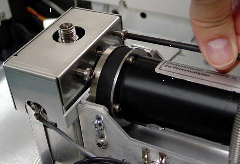
32 Inlets, detectors, and the oven are insulated with fibrous materials which may cause irritation to skin, eyes, and/or mucous membranes. Always wear gloves when working with the insulation. Additionally, if the insulation is flaky/crumbly, wear protective eyewear and a suitable breathing mask and/or respirator. Disconnect the column from the inlet and cap the column to minimize contamination. Remove the insulating cup and insulation from inside the oven. Remove the inlet cover. Note and record plumbing and wiring layouts and connectivity. Remove the assembly stepwise. You will need Torx T-10 and T-20 drivers. Disconnect the heater/sensor cable. Disconnect the 1/16-inch tubing pair from the EPC module. Remove the three top screws retaining the inlet to the GC. Gently lift the assembly up and out. Insert replacement inlet. Reassembly is the reverse of these steps. Use new O-rings during EPC reconnection. Refer to the following figures and photos for guidance. 32


33 33 If the EPC module is disconnected, the inlet can be removed and replaced.


34 This housing is designed to accommodate a variety of Agilent inlets. Note fibrous insulation within housing. See earlier warning. 34

35 Replacing the Purged Packed inlet heater 1 Cool down the oven. Turn off the GC main power switch and disconnect its power cord. 35
36 Hazardous voltages are present in the mainframe when the GC power cord is connected. Avoid a potentially dangerous shock hazard by disconnecting the power cord before removing any GC panels. Components can be damaged by static electricity: be sure to wear an ESD strap grounded to the GC chassis while performing this procedure. Inlets, detectors, and the oven are insulated with fibrous materials which may cause irritation to skin, eyes, and/or mucous membranes. Always wear gloves when working with the insulation. Additionally, if the insulation is flaky/crumbly, wear protective eyewear and a suitable breathing mask and/or respirator. Heater replacement requires removal of the inlet. Refer to Replacing the Purged Packed inlet (31) for removal instructions. 36
 block.")
37 With the inlet removed: 1 Remove the tubing nut and column adapter. Remove the bottom nut holding the thermal block. Slide the thermal block off the inlet weldment. Carefully remove the heater and sensor from the thermal (heater) block. 37
38 Replace heater/sensor cable assembly with a new unit. Reassembly is the reverse of these steps. 38
39 3 Detectors I Detector overview 39 About the detector signal boards 40 Accessing detector signal boards 41 Replacing detector signal boards 41 Flame Ionization Detector (FID) 43 Nitrogen Phosphorus Detector (NPD) 64 Thermal Conductivity Detector (TCD) 80 Micro-cell Electron Capture Detector (uecd)84 Flame Photometric Detector (FPD) 90 39
40 Detector overview A detector monitors the gas stream exiting from the analyzing column. Its electrical output changes when the composition of the gas does. This section deals with the most widely used detectors. About the detector signal boards The GC can control up to 2 detector signal boards and simultaneously process their digital signals. All detector boards are mounted in the electronics carrier on the right-hand side of the GC. Sometimes other problems seem like a signal board failure. Replace a signal board only after ruling out other possible causes as follows: 1 Verify the signal board is receiving 24 VDC power, the green LED is ON, and the board appears configured in the GC display. Check diagnostics for faults caused by components connected to the signal board, such as, ignitors, electrometers, filaments, and PMTs. Replace the signal board only after eliminating the possible causes listed in steps 1 and 2. Repairs should be verified by the following: Typical detector signal baseline output and noise. The types of detector signal boards, along with part numbers and possible locations, are listed in the table below. Table Detector signal boards Descriptio Part number Slot n uecd G F-DET or B-DET FID G F-DET or B-DET NPD G F-DET or B-DET TCD G F-DET or B-DET 40
41 FPD G F-DET or B-DET. Also uses AUX 1. Table Detector signal electrical connectors Descripti on P1 P2 P3 P4 Other uecd Communicati on buss Electromet er FID Communicati on buss Ignitor Electromete r NPD Communicati on buss Bead current Electromete r TCD Communicati on buss Switchi ng valve J4 Filaments FPD Communicati on buss High voltage Signal P5 - ignitor Accessing detector signal boards The front and back detector signal boards are located under the right-hand side panel. 1 Remove the detector top cover and the electronics top cover. Remove one screw on the side of the right hand side panel. Loosen one screw and remove one screw on the back of the GC. Slide the panel toward the back of the GC and lift off. Place the tip of the driver in one of the top ventilation slots and push back. Replacing detector signal boards 1 Cool down the oven. Turn off the GC main power switch and disconnect its power cord. 41
42 Hazardous voltages are present in the mainframe when the GC power cord is connected. Avoid a potentially dangerous shock hazard by disconnecting the power cord before removing any GC panels. Components can be damaged by static electricity: be sure to wear an ESD strap grounded to the GC chassis while performing this procedure. Remove the right-hand side panel for the electronics carrier. Disconnect the electrical cables to the board. 42

43 Turn the thumb screw counter-clockwise and lift the screw to disengage it from the sheet metal. Slide the board down and lift it out. When replacing the signal board, short boards, such as the FID and uecd, slide into 3 slots. Long boards, such as NPD and FPD, slide into 4 slots. Push in on the thumbscrew to engage the threads. Turn the screw clockwise until it is tight. The grounding point for the signal board is the thumbscrew. If this screw is not secured, the detector signal will be noisy and may cause damage to the board. Connect the electrical cables to the board. Turn ON the GC and reconfigure the detector signal board. See Replacing a GC module (166) for details. 43
44 Flame Ionization Detector (FID) The FID is the most widely used of the GC detectors. It responds to almost all organic compounds (there are a few exceptions), has good sensitivity and a wide linear range, and is easy to use. Selecting an FID jet Open the oven door and locate the column connection fitting at the base of the detector. It will look like adaptable fitting. If you have an application that tends to clog the jet, select a jet with a wider tip id. When using packed columns in high column-bleed applications, the jet tends to clog with silicon dioxide. In simulated distillation applications, the high-boiling hydrocarbons tend to clog the jet. For capillary optimized fittings, select a jet from the table below, "Jets for capillary optimized fittings". 44
 61.")
45 For adaptable fittings, select a jet from the table below, "Jets for capillary adaptable fittings". Table Jets for capillary adaptable fittings Figure 2 ID Jet type Part number Jet tip id Length 1 Capillary mm (0.011 inch) 61.5 mm 2 Capillary, hightemperature (use with simulated distillation) mm (0.018 inch) 61.5 mm 3 Packed mm (0.018 inch) 63.6 mm 4 Packed, wide-bore (use with high-bleed applications) mm (0.030 inch) 63.6 mm Figure Capillary adaptable jets 45
46 Replacing the FID interconnect assembly or spring 1 Cool down the oven. Turn off the GC main power switch and disconnect its power cord. Hazardous voltages are present in the mainframe when the GC power cord is connected. Avoid a potentially dangerous shock hazard by disconnecting the power cord before removing any GC panels. Components can be damaged by static electricity: be sure to wear an ESD strap grounded to the GC chassis while performing this procedure. Gather the following: New FID collector assembly. (See Consumables for the FID ( 324).) T-20 Torx screwdriver 1/4-inch nut driver Tweezers Lint-free gloves Shut off the detector and the detector gases and let the detector cool. To avoid contaminating the FID, wear clean, lint-free gloves when handling the collector assembly. Disconnect the ignitor cable assembly. 46


47 Remove the three screws holding the collector assembly to the mounting pallet. The next step exposes the interconnect spring. Be careful not to touch or disfigure the spring while working on the FID. Any dirt or bending will reduce the sensitivity of your detector. Lift and remove the assembly from the pallet. 47
 1 Remove the screws at each end of the electrometer body. DO NOT loosen the screw in the center of the electrometer cover.")
48 To replace the interconnect spring only 1 Pull the spring off the end of the interconnect. Push a new spring on. Reassemble the detector. To replace the interconnect (and spring) 1 Remove the screws at each end of the electrometer body. DO NOT loosen the screw in the center of the electrometer cover. The interconnect is held by a small spring clip. Remove the screw holding this clip. Disconnect the ribbon cable that connects the electrometer to the signal board. Remove the electrometer. There is a hex section where the interconnect enters the electrometer. Use a wrench to losen and remove the interconnect. Insert a new interconnect and tighten it firmly (do not overtighten!). Reassemble the detector. Replacing the heater 1 Cool down the oven. Turn off the GC main power switch and disconnect its power cord. 48
49 Hazardous voltages are present in the mainframe when the GC power cord is connected. Avoid a potentially dangerous shock hazard by disconnecting the power cord before removing any GC panels. Components can be damaged by static electricity: be sure to wear an ESD strap grounded to the GC chassis while performing this procedure. Turn off all gas flows at their sources. Inlets, detectors, and the oven are insulated with fibrous materials which may cause irritation to skin, eyes, and/or mucous membranes. Always wear gloves when working with the insulation. Additionally, if the insulation is flaky/crumbly, wear protective eyewear and a suitable breathing mask and/or respirator. Disconnect the column from the bottom of the detector. Remove the right side electronics panel. Access the FID module by unscrewing the single T-20 screw holding the GC cover over the detector(s). Raise it out of the way or remove it temporarily. Disconnect the heater/sensor cable from the heater/sensor connector. 49
50 Disconnect the ignitor cable from the FID signal board to the ignitor castle. Disconnect the electrometer cable from the FID signal board. (For the old version detector) Unscrew the three thumbscrews that secure the detector flow tubing to the EPC module. 50
51 51 (For the new version detector) Unscrew the captive screws that secure the detector flow tubing blocks to the EPC module.

52 Remove the four T-20 screws retaining the FID assembly to the GC. Lift the entire FID assembly up and off of the GC. Lay the assembly down on a clean flat surface. Examine the underside of the detector assembly. Remove the insulated cover over the heater block. Loosen the heater/sensor cable sufficiently to allow for the lifting and removal of the heater from the heater block. Carefully remove the defective heater/sensor cable and replace it with a new heater/sensor cable. Reassembly is the reverse of these steps. 52
53 Replacing the FID signal board 1 Cool down the oven. Turn off the GC main power switch and disconnect its power cord. Hazardous voltages are present in the mainframe when the GC power cord is connected. Avoid a potentially dangerous shock hazard by disconnecting the power cord before removing any GC panels. Components can be damaged by static electricity: be sure to wear an ESD strap grounded to the GC chassis while performing this procedure. Turn off all gas flows at their sources. Inlets, detectors, and the oven are insulated with fibrous materials which may cause irritation to skin, eyes, and/or mucous membranes. Always wear gloves when working with the insulation. Additionally, if the insulation is flaky/crumbly, wear protective eyewear and a suitable breathing mask and/or respirator. Remove the right side electronics panel from the GC. Lift up the GC detector cover to access the FID. Disconnect all electrical connections between the FID and the signal board. Rotate the FID board thumbscrew counterclockwise, lift the board up and then downward to remove it from the GC. Replace the defective board with a new FID board. Restore the FID electrical connections. Reassembly is the reverse of these steps. Reconfigure the GC using the software keypad, supplying the 53
54 requested information. Replacing the electrometer 1 Cool down the oven. Turn off the GC main power switch and disconnect its power cord. Hazardous voltages are present in the mainframe when the GC power cord is connected. Avoid a potentially dangerous shock hazard by disconnecting the power cord before removing any GC panels. Components can be damaged by static electricity: be sure to wear an ESD strap grounded to the GC chassis while performing this procedure. Turn off all gas flows at their sources. Inlets, detectors, and the oven are insulated with fibrous materials which may cause irritation to skin, eyes, and/or mucous membranes. Always wear gloves when working with the insulation. Additionally, if the insulation is flaky/crumbly, wear protective eyewear and a suitable breathing mask and/or respirator. Remove the right side electronics cover. Disconnect the electrometer ribbon cable from the FID signal board. Remove the Torx T-20 screw and clamp over the interconnect tube. Remove the two Torx T-20 screws from each end of the electrometer. 54

55 Lift the electrometer up and away. Replace the defective electrometer with a new one, making sure that there is firm contact between the interconnect spring and the collector. Reassembly is the reverse of these steps. After reassembly, turn the GC power on and reconfigure the modified detector using the software keypad, supplying the requested information. Replacing the glow plug (ignitor) 1 Cool down the oven. Turn off the GC main power switch and disconnect its power cord. Hazardous voltages are present in the mainframe when the GC power cord is connected. Avoid a potentially dangerous shock hazard by disconnecting the power cord before removing any GC panels. Components can be damaged by static electricity: be sure to wear an ESD strap grounded to the GC chassis while performing this procedure. 55
56 Inlets, detectors, and the oven are insulated with fibrous materials which may cause irritation to skin, eyes, and/or mucous membranes. Always wear gloves when working with the insulation. Additionally, if the insulation is flaky/crumbly, wear protective eyewear and a suitable breathing mask and/or respirator. Remove the right side electronics panel and identify the FID signal board. Disconnect the ignitor cable from the FID signal board. Lift up or remove the GC detector cover to access the FID. Unclip the ignitor cable from the cable extension to the FID board. 56
57 From the top, unscrew the defective ignitor cable from the ignitor castle. Replace the defective cable with a new ignitor cable. Reassembly is the reverse of these steps. Replacing the entire FID Before physically installing the detector and EPC into GC, power GC on and update firmware to A or higher. The new version detector requires GC FW revision A or higher. The lower FW revision would potentially result in wrong EPC frit constants uploaded. Refer to service note 7820A Update the GC firmware revision to A or higher To obtain the latest firmware revision, visit the Agilent website at irmware.aspx?whid= Cool down the oven. Turn off the GC main power switch and disconnect its power cord. 57
58 Hazardous voltages are present in the mainframe when the GC power cord is connected. Avoid a potentially dangerous shock hazard by disconnecting the power cord before removing any GC panels. Components can be damaged by static electricity: be sure to wear an ESD strap grounded to the GC chassis while performing this procedure. Turn off all gas flows at their sources. Inlets, detectors, and the oven are insulated with fibrous materials which may cause irritation to skin, eyes, and/or mucous membranes. Always wear gloves when working with the insulation. Additionally, if the insulation is flaky/crumbly, wear protective eyewear and a suitable breathing mask and/or respirator. Disconnect the column from the bottom of the detector. Remove the right side electronics panel. Access the FID module by unscrewing the single T-20 screw holding the GC cover over the detector(s). Raise the cover out of the way or remove it temporarily. Disconnect the heater/sensor cable to the FID. Disconnect the ignitor cable from the FID signal board. 58
59 59 Disconnect the electrometer cable from the FID signal board.
60 (For the old version detector) Unscrew the three thumbscrews that secure the detector flow tubing to the EPC module. (For the new version detector) Unscrew the captive screws that secure the detector flow tubing blocks to the EPC module. 60
61 Remove the four T-20 screws retaining the FID assembly to the mounting pallet. Lift the entire FID assembly up and off. At this point the entire unit can be replaced with a new or repaired unit. Reassembly is the reverse of these steps. After completing the reassembly turn the power on and reconfigure the GC from the software keypad. The frit constants update is NOT required for New Version Detectors. (Step 18 to 22 are for the old version detector only) Record the serial number located on the side of the detector. (Example TCD and FID labels shown, other detectors are similar.) 61
62 Locate the disk (CD) that came with the new detector. You will need it to upload the new detector's frit data into the GC. Start Instrument Utility (version B or greater), go to Firmware Update > Frit Constants, and connect to the GC. Use the software to upload the new frit constants. For details, follow the software online help. When prompted, reboot the GC. Perform a checkout test. Ultrasonic cleaning the FID The collector requires occasional cleaning to remove deposits (usually white silica from column bleed, or black, carbonaceous soot). Deposits reduce sensitivity and cause chromatographic noise and spikes. The cleaning procedure presented here suggests you use an ultrasonic bath to clean the collector and other parts of the detector. However, if your collector is not too dirty, it may be sufficient to scrub it with a nylon brush and then use a burst of compressed air or nitrogen to blow stray particles away. This procedure summarizes the general steps for cleaning the parts. You need to follow the standard safety practices of your laboratory for handling chemicals. For example, wear the appropriate safety eye glasses, lab coat, and gloves. Scratches on the FID jet affect its performance. If you choose to clean the jet, be sure not to scratch or bend the jet. The FID castle is coated with a layer of Teflon. Ultrasonic cleaning of this part for more than 5 to 10 seconds will damage this coating. 62
63 It is often more convenient to replace dirty jets with new ones than to clean them, especially jets that have been badly contaminated. 1 Gather the following: Small ultrasonic cleaning bath Aqueous detergent GC-grade methanol in a Teflon wash bottle. Wash bottles made of other materials usually contain plasticizer contaminants Dry, filtered, compressed air or nitrogen Clean cloth If you are cleaning the jet, run the cleaning wire through the tip of the jet. Run it back and forth a few times until it moves smoothly. Be careful not to scratch the jet. Place the parts in your glassware, cover them with the aqueous detergent, and place them in the ultrasonic bath. If you are cleaning the castle, sonicate for only 5 to 10 seconds. Push the wire brush through the collector. For other parts, sonicate for 1 to 5 minutes. Remove the parts from the bath. 63
.")
64 Push the wire brush through the collector. Rinse the parts in tap water or distilled water. Rinse all surfaces of the parts in methanol; inside and outside surfaces. To insure good rinsing use either a Teflon wash bottle or a beaker. From this point on, handle the parts only with forceps (or tweezers). Remove the jet from the bath and rinse it thoroughly with hot tap water and then with a small amount of methanol. Blow the jet dry with a burst of compressed air or nitrogen and then place the jet on a clean cloth to air dry. 64
65 Nitrogen Phosphorus Detector (NPD) The NPD is a variation on the FID, in that the sample is burned and the resulting ions are collected. However, the hydrogen/air ratio is set to suppress carbon ionization and an alkali salt enhances nitrogen and phosphorus ionization. Selecting an NPD jet Open the oven door and locate the column connection fitting at the base of the detector. It will look like either a capillary optimized fitting or an adaptable fitting. If you have an application that tends to clog the jet, select a jet with a wider tip id. When using packed columns in high column-bleed applications, the jet tends to clog with silicon dioxide. For adaptable fittings, select one of the following from the table below, "Jets for adaptable fittings". Table 37 Jets for adaptable fittings Figure 4 ID Jet type Part number Jet tip id Length 1 Capillary with extended jet (recommended) G mm (0.11 inch) 70.5 mm 2 Capillary mm (0.011 inch) 61.5 mm 65

66 3 Capillary, hightemperature mm (0.018 inch) 61.5 mm 4 Packed mm (0.018 inch) 63.6 mm Figure Adaptable NPD jets Removing the NPD electrometer 1 Cool down the oven. Turn off the GC main power switch and disconnect its power cord. Hazardous voltages are present in the mainframe when the GC power cord is connected. Avoid a potentially dangerous shock hazard by disconnecting the power cord before removing any GC panels. Components can be damaged by static electricity: be sure to wear an ESD strap grounded to the GC chassis while performing this procedure. Remove both the electronics top cover and the right side cover. 66
67 Lift up the hinged detector tower cover and remove the Torx T-20 screw and the clamp on the electrical interconnect. Loosen the three Torx T-10 screws on the lid weldment and remove the lid. Remove one Torx T-20 screw from each end of the electrometer. (You do not need to remove the screw on the top of the electrometer that holds the cover on.) Unlock and detach the electrometer's ribbon cable from the detector's interface board and lift the electrometer from the detector pallet. Reassembly is the reverse of these steps. Replacing the entire NPD Before physically installing the detector and EPC into GC, power GC on and update firmware to A or higher. The new version detector requires GC FW revision A or higher. The lower FW revision would potentially result in wrong EPC frit constants uploaded. Refer to service note 7820A
68 1 Update the GC firmware revision to A or higher To obtain the latest firmware revision, visit the Agilent website at ware.aspx?whid=58488 Cool down the oven. Turn off the GC main power switch and disconnect its power cord. Hazardous voltages are present in the mainframe when the GC power cord is connected. Avoid a potentially dangerous shock hazard by disconnecting the power cord before removing any GC panels. Components can be damaged by static electricity: be sure to wear an ESD strap grounded to the GC chassis while performing this procedure. Inlets, detectors, and the oven are insulated with fibrous materials which may cause irritation to skin, eyes, and/or mucous membranes. Always wear gloves when working with the insulation. Additionally, if the insulation is flaky/crumbly, wear protective eyewear and a suitable breathing mask and/or respirator. Remove the right side electronics panel. Disconnect the column from the bottom of the detector. Remove the electronics top cover. Disconnect the power/sensor cable to the NPD. Disconnect the electrometer cable from the NPD signal board. 68
69 (For the old version detector) Unscrew the three thumbscrews that secure the detector flow tubing to the EPC module. (For the new version detector) Unscrew the captive screws that secure the detector flow tubing blocks to the EPC module. Remove the four T-20 screws retaining the NPD pallet. 69
70 Lift the entire NPD unit up and off. At this point the entire unit can be replaced. Reassembly is the reverse of these steps. Restore power and reconfigure the GC using the keypad, supplying the requested information. The frit constants update is NOT required for New Version Detectors. (Step 15 to 19 are for the old version detector only) Record the serial number located on the side of the detector. (Example TCD and FID labels shown, other detectors are similar.) Locate the disk (CD) that came with the new detector. You will need it to upload the new detector's frit data into the GC. Start Instrument Utility (version B or greater), go to Firmware Update > Frit Constants, and connect to the GC. Use the software to upload the new frit constants. For details, follow the software online help. When prompted, reboot the GC. Perform a checkout test. Replacing an NPD signal board 1 Cool down the oven. Turn off the GC main power switch and disconnect its power cord. 70
71 Hazardous voltages are present in the mainframe when the GC power cord is connected. Avoid a potentially dangerous shock hazard by disconnecting the power cord before removing any GC panels. Components can be damaged by static electricity: be sure to wear an ESD strap grounded to the GC chassis while performing this procedure. Turn off all gas flows at their sources. Inlets, detectors, and the oven are insulated with fibrous materials which may cause irritation to skin, eyes, and/or mucous membranes. Always wear gloves when working with the insulation. Additionally, if the insulation is flaky/crumbly, wear protective eyewear and a suitable breathing mask and/or respirator. Wear lint-free gloves to minimize source contamination when servicing the bead assembly. Disconnect three electrical connections (to electrometer, to heater, and the 4-wire communication buss). Turn thumb screw counterclockwise, lift screw to disengage, slide board down, and then lift out. (Note that the grounding point for the board is at the thumbscrew.) Insert the replacement board. Reassembly is the reverse of these steps. 71
72 Reconfigure the modified GC from the software keypad, supplying requested information. Replacing the NPD heater 1 Cool down the oven. Turn off the GC main power switch and disconnect its power cord. Hazardous voltages are present in the mainframe when the GC power cord is connected. Avoid a potentially dangerous shock hazard by disconnecting the power cord before removing any GC panels. Components can be damaged by static electricity: be sure to wear an ESD strap grounded to the GC chassis while performing this procedure. Turn off the oven and all heated zones and let them cool. Turn off all gas flows at their sources. Turn off the GC main power switch and disconnect its power cord. 72
73 Inlets, detectors, and the oven are insulated with fibrous materials which may cause irritation to skin, eyes, and/or mucous membranes. Always wear gloves when working with the insulation. Additionally, if the insulation is flaky/crumbly, wear protective eyewear and a suitable breathing mask and/or respirator. Disconnect the column from the bottom of the detector. Remove the right side mainframe panel. Remove the electronics top cover. Disconnect the power/sensor cable to the NPD detector. Disconnect the electrometer cable from the NPD signal board. (For the old version detector) Unscrew the three thumbscrews that secure the detector flow tubing to the EPC module. (For the new version detector) Unscrew the captive screws that secure the detector flow tubing blocks to the EPC module. 73
74 Remove the four T-20 screws retaining the NPD assembly to the GC. Remove the NPD detector assembly from the GC. Examine the underside of the detector assembly. Cover or plug the sample inlet tube while servicing this unit to limit contamination. Remove the insulated cover over the heater/detector block. Loosen the heater cable sufficiently to allow for the lifting off and removal of the heater from the detector block. Remove and replace the entire heater/cable assembly. Reassembly is the reverse of these steps. Replacing the NPD electrometer 1 Cool down the oven. Turn off the GC main power switch and disconnect its power cord. 74
75 Hazardous voltages are present in the mainframe when the GC power cord is connected. Avoid a potentially dangerous shock hazard by disconnecting the power cord before removing any GC panels. Components can be damaged by static electricity: be sure to wear an ESD strap grounded to the GC chassis while performing this procedure. Turn off all gas flows at their sources. Inlets, detectors, and the oven are insulated with fibrous materials which may cause irritation to skin, eyes, and/or mucous membranes. Always wear gloves when working with the insulation. Additionally, if the insulation is flaky/crumbly, wear protective eyewear and a suitable breathing mask and/or respirator. Wear lint-free gloves to minimize source contamination when servicing the bead assembly. Remove both the electronics top cover and the right side cover. Lift up the hinged NPD cover and remove the T-20 screw and J-clamp on the interconnect assembly. Loosen the three Torx T-10 screws on the lid weldment and remove the lid. Remove one Torx T-20 screw from each end of the electrometer. Do not remove the screw on the top of the electrometer that holds the cover on. Disconnect the power/sensor cable from the bead assembly and from the NPD signal board. Unlock and detach the electrometer's ribbon cable from the NPD signal board and lift the electrometer up from the pallet. 75
.")
76 Reassembly is the reverse of these steps. Reconfigure the modified GC from the software keypad, supplying requested information. Cleaning the NPD jet and collector The collector requires occasional cleaning to remove deposits (usually white silica from column bleed, or black, carbonaceous soot). Deposits reduce sensitivity and cause chromatographic noise and spikes. The cleaning procedure presented here suggests you use an ultrasonic bath to clean the collector and other parts of the detector. However, if your collector is not too dirty, it may be sufficient to scrub it with a nylon brush and then use a burst of compressed air or nitrogen to blow stray particles away. 76
77 This procedure summarizes the general steps for cleaning the parts. You need to follow the standard safety practices of your laboratory for handling chemicals. For example, wear the appropriate safety eye glasses, lab coat, and gloves. Scratches on the NPD jet affect its performance. If you choose to clean the jet, be sure not to scratch or bend the jet. It is often more convenient to replace dirty jets with new ones than to clean them, especially jets that have been badly contaminated. 1 Gather the following: Small ultrasonic cleaning bath Aqueous detergent GC-grade methanol in a Teflon wash bottle. Wash bottles made of other materials usually contain plasticizer contaminates. Dry, filtered, compressed air or nitrogen Clean cloth If you are cleaning the jet, run the cleaning wire through the tip of the jet. Run it back and forth a few times until it moves smoothly. Be careful not to scratch the jet. Place the parts in your glassware, cover them with the aqueous detergent, and place them in the ultrasonic bath for 1 to 5 minutes. Remove the parts from the bath and push the wire brush through the collector. Rinse the parts in tap water or distilled water. 77
78 Rinse all surfaces of the parts in methanol; inside and outside surfaces. To insure good rinsing use either a Teflon wash bottle or a beaker. From this point on, handle the parts only with forceps (or tweezers). Remove the jet from the bath and rinse it thoroughly with hot tap water and then with a small amount of methanol. Blow the jet dry with a burst of compressed air or nitrogen and then place the jet on a clean cloth to air dry. Cleaning the NPD 1 Turn off all gas flows at their sources. Turn off the GC main power switch. Components can be damaged by static electricity: be sure to wear an ESD strap grounded to the GC chassis while performing this procedure. Inlets, detectors, and the oven are insulated with fibrous materials which may cause irritation to skin, eyes, and/or mucous membranes. Always wear gloves when working with the insulation. Additionally, if the insulation is flaky/crumbly, wear protective eyewear and a suitable breathing mask and/or respirator. Wear lint-free gloves to minimize source contamination when servicing the bead assembly. Remove the right side mainframe panel. Remove the electronics top cover. Disconnect the power/sensor cable to the NPD. Disconnect the electrometer cable from the NPD signal board. (For the old version detector) Unscrew the three thumbscrews that secure the detector flow tubing to the EPC module. 78
79 (For the new version detector) Unscrew the captive screws that secure the detector flow tubing blocks to the EPC module. Remove the four T-20 screws retaining the NPD assembly to the GC. Lift entire unit up and off. 79
80 Place unit on a clean surface. Lift up the hinged metal cover over the detector assembly. Remove the three T-10 screws retaining the bead assembly to the housing and then remove the bead assembly to prevent accidental damage. Do not touch the ceramic bead. Apply protective cap over the bead assembly, if available. Loosen the three captive T-20 screws retaining the lid. Lift the lid up and off. Using a pair of tweezers, carefully remove the three O-rings, two alumina insulators, and the collector assembly. At this point one can choose to clean only the parts removed or continue the disassembly to remove, clean, or replace the jet. Use a 1/4-inch deep-socket nut driver to unscrew the jet. Use slight side pressure on the nut driver to drag the jet up out of the detector weldment and then use tweezers to grasp and remove the jet. Reassembly is the reverse of these steps. 80
81 Thermal Conductivity Detector (TCD) The TCD is sometimes called the "universal" detector because it responds to anything that is not the carrier gas. Replacing the TCD detector cell 1 Cool down the oven. Turn off the GC main power switch and disconnect its power cord. Hazardous voltages are present in the mainframe when the GC power cord is connected. Avoid a potentially dangerous shock hazard by disconnecting the power cord before removing any GC panels. Components can be damaged by static electricity: be sure to wear an ESD strap grounded to the GC chassis while performing this procedure. 81 Turn off any detector gases at their supply. Shut off the detector and the detector gases and let the detector cool. Remove the detector cover, the electronics top cover, and the pneumatics cover. Disconnect the TCD filament leads which run from the detector to the detector interface card. Disconnect the wires from the detector interface card using a small flat blade screwdriver to push down on the connector tabs while you pull out the wires. Remove the cover and the insulation. Use a T-20 Torx screwdriver to remove the two screws securing the detector cell to the aluminum detector carrier bracket and lift
82 the cell from the bracket. Slide the heater/sensor assembly from the detector cell. Slide the PRT out of the detector cell. Install the new cell and reassemble the detector. Reassembly is the reverse of these steps with the following additional considerations: Before replacing the insulation, place the cap that came with your detector over the detector vent to prevent plugging the vent with insulation. Remove the cap once the insulation is in place. When replacing the detector cover, make sure that the hole in the top of the cover is positioned over the detector vent and that the filaments, plumbing and heater/sensor leads including the PRT leadsare positioned under the appropriate cut-outs on the sides of the cover. Make sure that only the filament wire is inserted into the connector, not the insulation sleeve. Then, check the filaments by tugging slightly on them. Check the PRT sensor lead connections to the detector card by tugging slightly on them. Replace the heater/sensor and PRT in the sensor holes as shown below. Make sure the PRT leads are properly installed. If the PRT leads are not properly installed in the detector card, filament burnout can occur. 82
83 Replacing the TCD switching valve 1 Turn off all gas flows at their sources. Turn off the GC main power switch. Components can be damaged by static electricity: be sure to wear an ESD strap grounded to the GC chassis while performing this procedure. Remove the detector top cover, the electronics cover. EPC module cover and the module retainer. 83

84 Trace the wires from the valve to the extension cable connector. Disconnect them. Loosen the screw holding the clamp and slide the old valve out. Examine the new valve. The plastic part has a flat side with 3 small O-rings. These must be placed over the 3 holes in the piece to which the screw connects. Slide the new valve into position (flat side against the metal) and place the clamp over it. Align the flat end of the valve with the flat metal surface next to it. Adjust the valve position until it lies flat against the adjacent metal. Tighten the clamp screw. There should be no gap between the plastic and the metal. If there is, loosen the clamp screw and repeat the adjustment. Reconnect the wires. Restore the covers. 84
85 Micro-cell Electron Capture Detector (uecd) This detector simply ignores most compounds, but responds with enormous sensitivity to electron-accepting species such as the halogens. Replacing the uecd heater/sensor assembly After removing the uecd detector from the GC, you can further disassemble it to replace the heater/sensor assembly. The ECD micro-cell contains radioactive 63 Ni. To reduce the risk of exposure, wear disposable gloves while handling the ECD micro-cell. When you are finished, dispose of the gloves and wash your hands with soap and water. 1 Remove the detector. Loosen the locking tab screw on top of the detector, slide the locking tab back, and pivot it out of the away. Lift the thermal cover up and carefully slide it off the anode assembly. Remove the two screws holding the upper heated block onto the assembly. Lift the block over the anode lead and remove. 85
86 Slide the heater and sensor out of the lower heated block. Replacing the uecd makeup gas adapter After removing the uecd detector from the GC, you can further disassemble it to replace the makeup gas adapter. The makeup gas adapter consists of a line from the detector pneumatics manifold that carries makeup gas to a weldment that screws into the bottom of the uecd detector. From there, the makeup gas sweeps past the end of the column and carries the column effluent into the uecd cell. 1 Remove the detector. Remove the Torx T-20 screw holding the pneumatics block(s) to the detector manifold. Slide the makeup gas adapter up and out of the GC. When re-installing the makeup gas adapter, ensure the following: Approximately 6 inches of the makeup gas line resides in the oven after installation. The makeup gas line is bent into a coil or loop (inside the oven) that loops around the bottom of the detector weldment and makeup gas adapter. 86
87 The end of the column does not protrude from the top of the makeup gas adapter. For most columns (outer diameter > 0.20 mm), insert the column as far as it will go into the gigabore liner. If using a microbore column (id < 0.20 mm) that passes completely through the liner, position the column so that the total length from the back of the capillary nut to the end of the column is about 69 to 71 mm. Frequency test Perform this test to make sure that the base frequency for the uecd during a blank run indicates a relatively contaminant-free system. See also the related troubleshooting manual topic on uecd Life Cycle. 87
88 It may take 24 hours for the uecd baseline to completely stabilize, especially if you are starting with a cold system and want to assure high-sensitivity operation. Therefore, for the most accurate results, run the detector at normal operating conditions for as long as possible (at least 2 hours and up to 24 hours) before running the frequency test. If you will be injecting into an unused inlet, you must use low-bleed septa. Make sure to condition new septa before use in an inlet for several hours with 1 to 5 ml/min carrier flow. 1 Make sure you are using normal operating conditions and that at least 2 hours have elapsed since the last run. Turn on the uecd and the corresponding signal. Check the displayed "Output": <25 = uecd frequency is acceptable 1000 = Contaminants in system Each display count equals a frequency of 1 Hertz (e.g., a display reading of 100 = 100 Hz.). If the uecd frequency indicates contamination ( 1000) check for the following: Contaminated carrier gas trap(s) and or supply replace carrier gas supply tank and any traps on the carrier supply line. Insufficient column conditioning fully condition the column. Contaminated detector bake out the detector. Column, inlet and/or septum bleed clean the inlet/replace the septum with a conditioned, low bleed septum. Leaks perform leak tests on both the inlet and detector systems. Anode current leakage make sure the anode contacts are clean. Make sure the anode nut is tight. 88
89 Leak test Once you have determined that the flow system components upstream from the detector (gas supply tubing, inlet, column fittings) are leak free, perform the following uecd detector leak test. 1 With the GC on and operating normally, set the oven, detector, and inlet temperatures to ambient. Turn off the uecd and then turn off the inlet pressure. Turn off the anode and makeup gas flows. Cap the uecd exhaust vent with a vent plug (part no ). Set carrier gas pressure at the inlet corresponding to the uecd to 15 psi (103 kpa). Wait until the system reaches the setpoint pressure and then turn off the pressure and monitor the actual pressure value for at least 10 minutes. Check for pressure drop: If the pressure stays stable or drops only 0.5 psi, you can consider the uecd leakfree. If the pressure drops more than 0.5 psi, you have a leak. If you are sure none of the upstream flow system components are leaking, check for leaks at the column fitting and plugged inlet. If you find leaks, tighten the fittings and repeat the leak test. If you can find no other leaks, the uecd itself is probably leaking. The uecd cannot be disassembled without special license from the Nuclear Regulatory Commission or Agreement State Licensing Agency (USA only). Return the leaking uecd to Agilent for disposal. Performing a radioactivity leak test (wipe test) Micro-cell ECDs must be tested for radioactive leakage at least every 6 months. Records of tests and results must be maintained 89
90 for possible inspection by the Nuclear Regulatory Commission and/or responsible state agency. More frequent tests may be conducted when necessary. The procedure used is the wipe test. A Wipe Test Kit (part no ) is supplied with each new uecd. Refer to the information card supplied in the Wipe Test Kit for instructions on performing the wipe test. 90
91 Flame Photometric Detector (FPD) The sample is burned in a hydrogen-rich flame. Excited species rise into a cooler zone above the flame, decay, and give off characteristic radiation. This is filtered and measured by a high-gain photomultiplier. The intense yellow carbon radiation is blocked by a shield around the flame. Filters select either sulfur or phosphorus radiation. Preparing for maintenance 1 Turn off all gas flows at their sources. Turn off the GC main power switch. Components can be damaged by static electricity: be sure to wear an ESD strap grounded to the GC chassis while performing this procedure. To prevent damage to the column or columns, remove the columns from the GC. Additional tasks in preparation include: If you are replacing the transfer line, turn off the source gases to the FPD detector. If you are not replacing the transfer line, plug base of transfer line with a 1/8-inch Swagelok nut to keep it clean. Disassembling the FPD Our objective is to disassemble the detector and prevent it from getting dirty. We recommend using lint free gloves during most of these steps. 1 Disconnect the spring and remove the photomultiplier tube (PMT). Place it in a safe place away from the light. 91


92 92 Remove and set aside the filter in a lint free cloth. For sulfur, remove the plastic spacer and then the filter. Try tapping the side of the detector or using the edge of a cotton swab. The phosphorus filter sits closer to the end of the housing.


93 93 Remove the vent or exhaust tube with a 9/16-inch wrench.
94 94 Remove the 4 screws and detector cover with a Torx T-20 driver.
95 95


96 Loosen one screw and remove the ignitor collar with a Torx T-10 driver. The collar of your ignitor may have 1 or 2 screws. Remove the heater/sensor assembly from the emission block. 96


97 97 Remove one screw and retainer for the heater/sensor assembly in the transfer line with a Torx T-10 Key.

98 Remove the heater/sensor assembly. Move the heater/sensor assemblies and ignitor cable to the front of the oven top. Remove two 7-mm mounting nuts from the base of the transfer line. Loosen 3 screws that hold the optics assembly to the detector bracket with a Torx T-10 driver. 98
99 99 The objective of this step is to separate the optics from the transfer line. Do not flex the tubing where it is brazed to the transfer line weldment. Grasp the transfer line with your left hand and the optics assembly with your right hand. Lift them just high enough so that the 3 screws that you loosened in step 11 are above the bracket.

100 Twist and lift the optics while holding the transfer line stationary. Carefully separate the assemblies. The O-ring on the transfer jet is compressed against the inside of the emissions chamber. This is the resistance that you feel. Place the optic assembly on a lint free cloth. 100

101 If you are not replacing the transfer line, skip to the section Rebuilding the optics assembly ( 101). If you are replacing the transfer line, continue with the next section. Rebuilding the FPD optics assembly Use lint-free gloves when handling the optics assembly and O-ring seal. 1 Completely loosen the 4 T-10 screws from the clamp and coupling. 101


102 Set the Y-shaped clamp to one side. Carefully separate the lens housing from the stainless steel coupling. The focusing lens and O-ring usually stick to the coupling, but could stay with the lens housing. Try to keep the housing, flange ring, screws and washers in place. Remove the brown O-ring on the lens housing with a small pick. Roll the new seal over the edge of the housing until it sits in the 102

103 groove. Remove the coupling and heat shield disk from the old emission chamber with a No 1 Pozidrive or Philips screwdriver. Try to keep the screws, washers, and parts together. 103


104 Assemble the ignitor parts. Slip the stainless steel spacer over the glow plug, followed by the O-ring. Do not use the copper washer. Screw the glow plug into the new emission chamber and tighten with a 5/16-inch wrench. Assemble the new emission chamber, seal, and window. 104


105 Position the heat shield and coupling onto the emission chamber so the threaded hole is aligned with the threaded fitting for the exhaust tube. Reconnect the parts using the 4 screws and washers. Tighten opposite screws, similar to a wheel on an automobile, to insure a good seal. 105


106 106 Turn the lens housing so that it faces the coupling. Insert the lens and rust colored O-ring.


107 Place the housing onto the coupling and fasten the top screw just tight enough to keep the parts together. Hold the y-shaped clamp and start the remaining screws into the clamp. Do not tighten until step 7 of Reassembling the detector ( 108). 107

108 Reassembling the FPD This part of the procedure reassembles the optics assembly with the transfer line, reconnects both to the detector bracket, replaces the heater/sensor and ignitor wires, replaces the covers and PMT. 1 Replace or install the O-ring on the transfer line jet. Remove the O-ring with a small pick. Place the new O-ring over the jet. Roll it into the groove below the jet. 108


109 Reposition the detector optics above the bracket. The objective of this step is to reattach the optics to the transfer line and insure a good seal between the O-ring and the emissions chamber. Grasp the transfer line with your left hand and the optics assembly with your right hand. Push them together while twisting back and forth. Before lowering the assemblies into the bracket, make sure there is no gap between the transfer line and the emission chamber. 109
110 110
111 111 Lower the assemblies into the bracket. Line up the holes in the transfer line base with the threaded posts in the bracket. Line up the 3 screws and the clamp with the notches in the detector bracket.


112 Reattach the transfer line to the bracket with the 7-mm nuts. Tighten the clamp against the detector bracket. Tighten the 3 bottom screws on the optics assembly. Insert the heater/sensor assembly into the transfer line. Make sure the sensor is at the bottom of the hole. Reinstall the retainer and screw. 112


113 113


114 Insert the heater/sensor assembly into the emission chamber. Reconnect the ignitor wire to the glow plug. 114

115 115 Replace the cover. First, start the 2 screws on the right-hand side of the cover. Second, start and tighten the screws at the base on the left-hand side. Third, tighten the screws on the right-hand side.

116 116

117 Replace the filter. If you are doing the Agilent checkout, run the phosphorus filter before the sulfur filter with spacer. Replace the photomultiplier tube (PMT). Connect the spring. Install the new vent tube. Make sure it is tight to prevent light leaks. Replacing the FPD 1 Before this can be done you must first disconnect some cables originating from the FPD board in the electronics panel. 117


118 From the side panel side, disconnect heater sensors to the Aux heater and to the back detector, the ignitor cable, the high voltage connector, and the PMT signal cable. Remove the top four T-20 screws retaining the PMT assembly. Lift up the entire assembly and lay it down on the top GC surface. 118
119 Loosen the one screw holding the adjacent cover and pivot the cover up and off. The FPD is now ready for replacement, if required. If not, reassembly is the reverse of these steps. Bake out and run checkout test This part of the procedure bakes out the detector and restores conditions. The detector output will level off in about 1 hour after you restore the conditions. The detector output will continue to drift down slowly for about 24 hours. 1 Reinstall the column or columns. Reinstall the drain tube to the FPD exhaust tube. Restore the gases to the GC. Restore the power to the GC. Restore the conditions to the inlets and detectors, but turn off the flame of the FPD to prevent condensation. After the FPD is at temperature for about 10 minutes, light the flame. Bake out the detector. Set the oven and detector temperatures to 250 C for 15 minutes. Insure there is adequate gas flows through the column. After the bakeout, restore the oven and FPD conditions. Allow the output to level off. Run a checkout and compare the results. Replacing the heater/sensor assemblies Replacing the heater/sensor assemblies takes about 30 minutes. It requires you to turn off the GC, remove the vent, and the detector cover. When turning the GC off, turn off the flame first to prevent condensation from dripping into the jet and column. You may wish to replace or check the FPD heater/sensor assemblies for the following reasons: 119
120 One or both of the heaters or sensors are defective. The actual temperature reading on the display of the heaters is cycling more than 1 C. Materials needed G Heater/Sensor assembly with short lead for the emissions block assembly. G Heater/Sensor assembly with long lead for the transfer line. Procedure 1 Turn off the flame. Turn off the GC. Remove the vent assembly and cover. Put on an ESD wrist strap. Remove the right-side cover to access the GC electronics. Disconnect the heater/sensor leads from the auxiliary heater board and the connectors above the main board. Carefully pull the cables up onto the top of the GC. Transfer line 1 Use a Torx T-10 driver to remove the screw and retainer clip holding the lower heater/sensor assembly. Remove the heater and sensor from the transfer line. Remove the protective cap from the temperature sensor of the heater/sensor assembly with the short cable. Insert the heater and sensor into the transfer line. Make sure the sensor is seated at the bottom of the hole. If not, the AUX temperature will wander above and below the detector setpoint. 120


121 121 Position the retainer clip over the heater/sensor assembly and install the screw.

122 Emissions block assembly 1 Remove the upper heater and temperature sensor from the emissions block assembly. Remove the protective cap from the sensor of the heater/sensor assembly with the long cable. Install the upper heater and sensor in the emissions block assembly. Closing up 1 Route the heater/sensor cables out of the bracket as shown. Replace the cover and vent assembly. Carefully thread the heater/sensor cables into the electronics compartment. Put on an ESD wrist strap. Connect the short cable as shown in Replacing the FPD ( 117). Connect the long cable to the auxiliary heater board. Replace the right-side cover to the GC electronics compartment. Turn on the GC. Confirm that the flame is off. Restore the operating conditions. 122

123 Wait 20 minutes for the detector to heat up, then ignite the flame. Long cable connectors and leads Detector type Location Connecto r Single-waveleng th Single-waveleng th Front Back A1 A1 Replacing the FPD signal board If changing the GC configuration, see Changing the GC configuration ( 167) for important information regarding GC methods. Then proceed with the steps below. 1 Cool down the oven and all heated zones. Turn off all gas flows at their sources. Turn off the GC main power switch and disconnect its power cord. 123
124 Hazardous voltages are present in the mainframe when the GC power cord is connected. Avoid a potentially dangerous shock hazard by disconnecting the power cord before removing any GC panels. Components can be damaged by static electricity: be sure to wear an ESD strap grounded to the GC chassis while performing this procedure. Disconnect all attached electrical connections to the FPD board. Turn thumb screw counterclockwise, lift screw to disengage, slide board down, and then lift out. (Note that the grounding point for the board is at the thumbscrew). Replace board if required. (Note that the FPD board is longer than the FID board and is attached to the full length of the GC board receptacle.) Replace connections in reverse order of disassembly. Reconfigure the modified GC from the software keypad supplying requested information. 124
125 4 EPC modules EPC overview 125 Repairing EPC modules 126 Accessing EPC modules 127 Replacing the EPC modules 127 Replacing EPC module proportional valves
126 EPC overview An Electronic Pneumatic Controller (EPC) module senses gas pressure or mass flow and controls that pressure or flow. There are 3 kinds of EPC modules: Inlet flow modules Detector flow modules Pneumatic control modules (PCM) Inlet modules are each designed for specific inlets. A PCM has one control channels, intended for carrier gas. Repairing EPC modules 126 The 7820A can control up to 4 EPC modules. Each has a particular purpose and is limited to a particular location in the EPC carrier. Repairs on EPC modules should be in this order: 1 Verify the EPC module is receiving 24 VDC power, the green LED is ON, and the EPC appears configured in the GC display. Compare the Communication buss connection with an adjacent module that has a good power and signal connection. If detector flows are incorrect, reload the correct frit values for the detector body. Replace proportional valve or valves for flow or pressure problems. Replace the module only after checking items 1 and 2 (when dealing with power issues). Repairs should be verified by the following: Zero the pressure channels before performing any verification tests. Inlets: With the inlet capped, perform pressure decay test. With column installed, compare calculated flow reading from
127 Accessing EPC modules the display with measured flow for column and split vent. Detectors: With the detector capped, compare calculated flow readings from the display with measured flow for each gas. Failure modes for a proportional valve include: Sticking solenoid plunger causing variable flows. Electronic open causing no flow. Valve failed in a closed position. 1 Turn off all gas flows at their sources. Turn off the GC main power switch. Components can be damaged by static electricity: be sure to wear an ESD strap grounded to the GC chassis while performing this procedure. Remove the top rear cover. Disconnect the gas plumbing to the module that is being replaced. In some cases, it may be necessary to remove the upper rear cover. 127
128 Replacing the EPC modules 1 Access the EPC module. See Accessing EPC modules ( 127). Hazardous voltages are present in the mainframe when the GC power cord is connected. Avoid a potentially dangerous shock hazard by disconnecting the power cord before removing any GC panels. Components can be damaged by static electricity: be sure to wear an ESD strap grounded to the GC chassis while performing this procedure. EPC modules are secured by one clamp on the top edge. Remove the retaining clamps holding the EPC module in place. Remove the 1/8 inch Swagelok gas supply tubing connections (1, 2, or 3) from the EPC module. Lift the EPC module up and remove the communication buss connector. The SSL EPC modules also require removal of an electrical connector to the split vent valve. Remove the tubing blocks (for an inlet or PCM) or manifold connections (for the detector universal EPC). Remove the EPC module by lifting straight up. Install the new EPC module. Remember to plug in the Communication buss. If a SSL also plug in the split vent valve. Remove the O-rings for the pneumatic tubing blocks (as applicable). Clean the sealing surface under the O-rings with a lint-free cloth. Install new O-rings. Install the new pneumatic tubing blocks or manifold connections and tighten. Turn ON the GC and configure the EPC module. Zero the flow and/or pressure sensors (Options / Calibrations). Verify the flow or pressure control. 128


129 Replacing EPC module proportional valves This is a generalized procedure for replacing all EPC proportional valves. Select the valve and valve part number from EPC modules ( 357). Valves come in a kit with spare O-rings and screws. 1 To protect the column and inlet liner, cool all heated zones in the GC. Turn off instrument. If you need to lift the EPC module to access the wire connectors, remove the retaining brackets. Lift the EPC module and disconnect the 2-wire connector from the printed circuit board. The figure shows an FID EPC module, which has three proportional valves. Using a T-10 driver, remove the two retaining screws holding the proportional valve to the EPC module. Save and reuse the screws if you did not get them in the kit. 129

130 Remove the valve and the O-rings. Clean the seat of the O-ring on the flow block with a lint free cloth. Insert 2 new O-rings. Except for the split vent valve, tie a loose knot in the proportional valve wire to shorten the wire. Attach the new proportional valve, the electrical connector, the EPC retaining clamps, and body panels. 130
131 5 Performance Verification About Chromatographic Checkout 131 To Prepare for Chromatographic Checkout 132 To Check FID Performance 132 To Check NPD Performance 136 To check TCD Performance 140 To Check uecd Performance 145 To Check FPD Performance (Sample )149 About Chromatographic Checkout The tests described in this section provide basic confirmation that the GC and detector can perform comparably to factory condition. However, as detectors and the other parts of the GC age, detector performance can change. The results presented here represent typical outputs for typical operating conditions and are not specifications. The tests assume the following: Use of an automatic liquid sampler. If not available, use a suitable manual syringe instead of the syringe listed. Use of a 10-µL syringe in most cases. However, a 5-µL syringe is an acceptable substitute for the 1-µL injections described here. Use of the septa and other hardware (liners, jets, adapters, and so forth) described. If you substitute other hardware, performance can vary. 131
132 To Prepare for Chromatographic Checkout Because of the differences in chromatographic performance associated with different consumables, Agilent strongly recommends using the parts listed here for all checkout tests. Agilent also recommends installing new consumable parts whenever the quality of the installed ones is not known. For example, installing a new liner and septum ensures that they will not contribute any contamination to the results. 1 Check the indicators/dates on any gas supply traps. Replace/recondition expended traps. Install new consumable parts for the inlet and prepare the correct injector syringe (and needle, as needed). Recommended part for Part number checkout Split splitless inlet Syringe, 10-µL O-ring Septum Liner (FID) or (other detectors) Packed column inlet Syringe, 10-µL O-ring Septum To Check FID Performance 1 Gather the following: Evaluation column, HP-5 30 m 0.32 mm 0.25 µm (19091J-413) FID performance evaluation (checkout) sample ( ) Chromatographic-grade isooctane (wash solvent) 4-mL solvent and waste bottles or equivalent for autoinjector 2-mL sample vials or equivalent for sample 132
133 Verify the following: Capillary column jet installed. If not, select and install a capillary column jet. Capillary column adapter installed (adaptable FID only). If not, install it. Chromatographic-grade gases plumbed and configured: helium as carrier gas, nitrogen, hydrogen, and air. (Nitrogen is an acceptable alternate carrier gas.) Empty waste vials loaded in sample turret. 4-mL solvent vial with diffusion cap filled with isooctane and inserted in Solvent A injector position. Install the evaluation column. (See the procedure for the SS or PP in the Maintenance manual.) Bake out the evaluation column for at least 30 min at 180 C. (See the procedure for the SS or PP in the Maintenance manual.) Be sure to configure the column. Check the FID baseline output. The output should be between 5 pa and 20 pa and relatively stable. (If using a gas generator or ultra pure gas, the signal may stabilize below 5 pa.) If the output is outside this range or unstable, resolve this problem before continuing. If the output is too low: Check that the electrometer is on. Check that the flame is lit. Create or load a method with these parameter values. Table 1. FID Checkout Conditions Column and sample Type HP-5, 30 m 0.32 mm 0.25 µm (19091J-413) Sample FID checkout Column flow 6.5 ml/min Column mode Constant flow Split/splitless inlet Temperature 250 C Mode Purge flow Splitless 40 ml/min 133
134 Purge time 0.5 min Gas saver Off Purged packed inlet Temperature 250 C Detector Temperature 300 C H2 flow Air flow Makeup flow (N2) Lit offset 30 ml/min 400 ml/min 25 ml/min Oven Initial temp 75 C Initial time Typically 2 pa 0.5 min Rate 1 20 C/min Final temp 190 C Final time 0 min ALS settings (if installed) Sample washes 2 Sample pumps 6 Sample wash volume 8 Injection volume 1 µl Syringe size 10 µl Solvent A pre washes Solvent A post washes Solvent A wash volume Solvent B pre washes Solvent B post washes Solvent B wash volume Injection mode Normal Airgap volume 0.20 Viscosity delay s Inject Dispense 6000 Speed PreInjection dwell 0 PostInjection dwell Manual injection 0 134
135 Injection volume 1 µl Data system Path Method and Run Control View: Instrument>Edit Parameters>Option s Method and Run Control View: Instrument>Edit Parameters>Signal s Setting Keep instrument keyboard locked after method is loaded? = No Assign Signal 1 to the detector Choose Save Data All Data Rate = 5 Hz If using a data system, prepare the system to perform one run using the loaded checkout method. Make sure that the data system will output a chromatogram. Start the run. If performing an injection using an autosampler, start the run using the data system or press [Start] on the GC. If performing a manual injection (with or without a data system): a b Press [Prep Run] to prepare the inlet for splitless injection. When the GC becomes ready, inject 1 µl of the checkout sample and press [Start] on the GC. The following chromatogram shows typical results for a new detector with new consumable parts installed and nitrogen makeup gas. 135
136 Typical values The following are typical values for the detector results. The results for a detector depend on site preparation related factors. These are not pass/fail criteria. Components C13 and C14 C15 and C16 Typical area counts 41 pa-sec 410 pa-sec If the detector is very quiet, area counts may be lower than these typical measurements. If so, use an MDL measurement to assess detector health. Minimum detectable level for tridecane : < 3 pg C/sec Repeatability (6 runs, first deleted to avoid first run anomalies): RSD% of RT < 0.06%; RSD% of area < 2%. Split: C13/C16 and C14/C16 sensitivity ratios: >0.95 and <1.05 To Check NPD Performance Gather the following: Evaluation column, HP-5 30 m 0.32 mm 0.25 µm
137 (19091J-413) NPD performance evaluation (checkout) sample ( ) 4-mL solvent and waste bottles or equivalent for autoinjector Chromatographic-grade isooctane 2-mL sample vials or equivalent for sample Verify the following: Capillary column jet installed. If not, select and install a capillary column jet. Capillary column adapter installed. If not, install it. Chromatographic-grade gases plumbed and configured: helium as carrier gas, nitrogen, hydrogen, and air. Empty waste vials loaded in sample turret. 4-mL vial with diffusion cap filled with isooctane and inserted in Solvent A injector position. If present, remove any protective caps from the inlet manifold vents. Install the evaluation column. (See the procedure for the SS or PP in the Maintenance manual.) Bake out the evaluation column for at least 30 min at 180 C. (See the procedure for the SS or PP in the Maintenance manual.) Be sure to configure the column. Create or load a method with these parameter values. Table 2. NPD Checkout Conditions Column and sample Type HP-5, 30 m 0.32 mm 0.25 µm (19091J-413) Sample NPD checkout Column mode Column pressure Split/splitless inlet Temperature 200 C Mode Splitless Purge flow Constant flow 6.5 ml/min (helium) 60 ml/min 137
138 Purge time 0.75 min Packed column inlet Temperature 200 C Detector Temperature 300 C H2 flow 3 ml/min Air flow Makeup flow (N2) Output Oven 60 ml/min Initial temp 60 C Initial time 0 min Rate 1 Makeup + column = 10 ml/min 30 display units (30 pa) 20 C/min Final temp 200 C Final time 3 min ALS settings (if installed) Sample washes 2 Sample pumps 6 Sample wash volume 8 Injection volume 1 µl Syringe size 10 µl Solvent A pre washes Solvent A post washes Solvent A wash volume Solvent B pre washes Solvent B postwashes Solvent B wash volume Injection mode Normal Airgap volume 0.20 Viscosity delay 0 Inject Dispense Speed PreInjection dwell 0 PostInjection dwell Manual injection 6000 Injection volume 1 µl 0 138
139 Data system Path Method and Run Control View: Instrument>Edit Parameters>Option s Method and Run Control View: Instrument>Edit Parameters>Signal s Setting Keep instrument keyboard locked after method is loaded? = No Assign Signal 1 to the detector Choose Save Data All Data Rate = 5 Hz If using a data system, prepare the system to perform one run using the loaded checkout method. Make sure that the data system will output a chromatogram. Start the run. If performing an injection using an autosampler, start the run using the data system or press [Start] on the GC. If performing a manual injection (with or without a data system): a b Press [Prep Run] to prepare the inlet for splitless injection. When the GC becomes ready, inject 1 µl of the checkout sample and press [Start] on the GC. The following chromatogram shows typical results for a new detector with new consumable parts installed. 139
140 Typical values The following are typical values for the detector results. The results for a detector depend on site preparation related factors. These are not pass/fail criteria. Agilent ChemStation SS/PP Sensitivity Azobenzene area 34 counts Malathion area counts 64 Agilent ChemStation ASTM noise Measured with GC 100 C 10 minute blank run, noise range(s) >1 minute Performance + noise report NPD ASTM noise 0.85 pa 3396B or 3396C or 3397A integrator sample conditions with analog input [GC Analog output, Range 0] >>Set DATE and TIME<< Zero 10 Pk wd 0.04 Att 2^ 7 Thresh 7 Cht sp 1 [Stop time 12.0] Ar Rej 1000 Sensitivity Azobenzene area counts 34 SS/PP Malathion area counts 64 To check TCD Performance Gather the following: Evaluation column, HP-5 30 m 0.32 mm 0.25 µm (19091J-413) FID/TCD performance evaluation (checkout) sample ( ) 4-mL solvent and waste bottles or equivalent for autoinjector Chromatographic-grade hexane
141 2-mL sample vials or equivalent for sample Chromatographic-grade helium as carrier, makeup, and reference gas Verify the following: Chromatographic-grade gases plumbed and configured: helium as carrier gas, nitrogen, hydrogen, and air. Empty waste vials loaded in sample turret. 4-mL solvent vial with diffusion cap filled with isooctane and inserted in Solvent A injector position. Install the evaluation column. (See the procedure for the SS or PP in the Maintenance manual.) Bake out the evaluation column for at least 30 min at 180 C. (See the procedure for the SS or PP in the Maintenance manual.) Be sure to configure the column. Create or load a method with these parameter values. TCD Checkout Conditions Column and sample Type HP-5, 30 m 0.32 mm 0.25 µm (19091J-413) Sample FID/TCD checkout Column flow Column mode 6.5 ml/min Split/splitless inlet Temperature 250 C Mode Purge flow Purge time Purged packed inlet Constant flow Splitless 60 ml/min 0.75 min Temperature 250 C Detector Temperature 300 C Reference flow (He) Makeup flow (He) Baseline output 20 ml/min 2 ml/min Oven Initial temp 40 C < 30 display counts on Agilent ChemStation (< 750 µv) 141
142 Initial time 0 min Rate 1 25 C/min Final temp 90 C Final time 0 min Rate 2 15 C/min Final temp 170 C Final time 2 min ALS settings (if installed) Sample washes 2 Sample pumps 6 Sample wash volume 8 Injection volume 1 µl Syringe size 10 µl Solvent A pre washes Solvent A post washes Solvent A wash volume Solvent B pre washes Solvent B post washes Solvent B wash volume Injection mode Normal Airgap volume 0.20 Viscosity delay 0 Inject Dispense 6000 Speed PreInjection dwell 0 PostInjection dwell Manual injection Injection volume 1 µl Data system Path Method and Run Control View: Instrument>Edit Parameters>Option s Setting loaded? = No 142
143 Method and Run Control View: Instrument>Edit Parameters>Signal s Assign Signal 1 to the detector Choose Save Data All Data Rate = 5 Hz Display the signal output. A stable output at any value between 12.5 and 750 µv (inclusive) is acceptable. If the baseline output is < 0.5 display units (< 12.5 µv), verify that the detector filament is on. If the offset is still <0.5 display units (< 12.5 µv), your detector requires service. If baseline output is > 30 display units (> 750 µv), there may be chemical contamination contributing to the signal. Bakeout the TCD. If repeated cleanings do not give an acceptable signal, check gas purity. Use higher purity gases and/or install traps. If using a data system, prepare the system to perform one run using the loaded checkout method. Make sure that the data system will output a chromatogram. Start the run. If performing an injection using an autosampler, start the run using the data system or press [Start] on the GC. If performing a manual injection (with or without a data system): a b Press [Prep Run] to prepare the inlet for splitless injection. When the GC becomes ready, inject 1 µl of the checkout sample and press [Start] on the GC. The following chromatogram shows typical results for a new detector with new consumable parts installed. 143
144 The following are typical values for the detector results. The results for a detector depend on site preparation related factors. These are not pass/fail criteria. Agilent ChemStation SS PP Sensitivity C, C, C area counts Discrimination C /C area ratio / / Agilent ChemStation ASTM noise Measured with GC isothermal at 100 C 10 minute blank run, noise range(s) > 1 minute Performance + noise report TCD ASTM noise display units (25 µv/display unit) Detector signal set to 5 Hertz B or 3396C or 3397A integrator sample conditions with analog input (GC Analog
145 output, Range 0) >>Set DATE and TIME<< Zero 10 Pk wd 0.04 Att^2 7 Thresh 5 Cht sp 1 Stop time 8.75 Ar Rej 1000 SS PP Sensitivity C, C, C area counts Discrimination C /C area ratio / / To Check uecd Performance Gather the following: Evaluation column, HP-5 30 m 0.32 mm 0.25 µm (19091J-413) uecd performance evaluation (checkout) sample ( , Japan: ) 4-mL solvent and waste bottles or equivalent for autoinjector Chromatographic-grade isooctane 2-mL sample vials or equivalent for sample Verify the following: Clean fused silica indented mixing liner installed. If not, install it. Chromatographic-grade gases plumbed and configured: helium as carrier, nitrogen as makeup. (Nitrogen is an acceptable alternate carrier gas.) Empty waste vials loaded in sample turret. 4-mL vial with diffusion cap filled with hexane and inserted in Solvent A injector position. Install the evaluation column. (See the procedure for the SS or PP in the Maintenance manual.) Bake out the evaluation column for at least 30 minutes at
146 180 C. (See the procedure for the SS or PP in the Maintenance manual.) Be sure to configure the column. Display the signal output to determine baseline output. A stable baseline output at any value between 0.5 and 1000 Hz (ChemStation display units) (inclusive) is acceptable. If the baseline output is < 0.5 Hz, verify that the electrometer is on. If the offset is still < 0.5 Hz, your detector requires service. If the baseline output is > 1000 Hz, there may be chemical contamination contributing to the signal. Bakeout the uecd. If repeated cleanings do not give an acceptable signal, check gas purity. Use higher purity gases and/or install traps. Create or load a method with the parameter values listed in the table below. Table 3. uecd Checkout Conditions Column and sample Type HP-5, 30 m 0.32 mm 0.25 µm (19091J-413) Sample µecd checkout ( or Japan: ) Column mode Column pressure Split/splitless inlet Temperature 200 C Mode Splitless Purge flow Purge time Purged packed inlet Constant flow 6.5 ml/min (helium) 60 ml/min 0.75 min Temperature 200 C Detector Temperature 300 C Makeup flow (N2) Baseline output Oven 30 ml/min (constant + makeup) Should be < 1000 display counts in Agilent ChemStation (< 1000 Hz) 146
147 Initial temp 80 C Initial time Rate 1 0 min 15 C/min Final temp 180 C Final time 10 min ALS settings (if installed) Sample washes 2 Sample pumps 6 Sample wash volume 8 Injection volume 1 µl Syringe size 10 µl Solvent A pre 2 washes Solvent A post 2 washes Solvent A wash volume Solvent B pre washes Solvent B post washes Solvent B wash volume Injection mode Normal Airgap volume 0.20 Viscosity delay 0 Inject Dispense 6000 Speed PreInjection dwell 0 PostInjection dwell Manual injection Injection volume 1 µl Data system Path Method and Run Control View: Instrument>Edit Parameters>Option s Method and Run Control View: Instrument>Edit Parameters>Signal s 0 Setting Keep instrument keyboard locked after method is loaded? = No Assign Signal 1 to the detector Choose Save Data All Data Rate = 5 Hz 147
148 If using a data system, prepare the system to perform one run using the loaded checkout method. Make sure that the data system will output a chromatogram. Start the run. If performing an injection using an autosampler, start the run using the data system or press [Start] on the GC. If performing a manual injection (with or without a data system): a b Press [Prep Run] to prepare the inlet for splitless injection. When the GC becomes ready, inject 1 µl of the checkout sample and press [Start] on the GC. The following chromatogram shows typical results for a new detector with new consumable parts installed. 148
149 Typical values The following are typical values for the detector results. The results for a detector depend on site preparation related factors. These are not pass/fail criteria. Agilent ChemStation Noise ([N3]) Measured by ChemStation, ASTM [N3] 4 Hz Signal Area, Lindane peak B or 3396C or 3397A integrator sample conditions with analog input [GC Analog output, Range 0] >>Set DATE and TIME<< GC Analog output Noise ([N1]) Measured at [GC Range 0], [3396 Attn. 3, Chart speed 1, zero 40 mm (for 1 min measurement) 50] Signal GC Range Zero 10 Pk wd 0.04 Att 2^ 5 Thresh 5 Cht sp 1 Stop time 11.0 Ar Rej Area, Lindane peak
150 To Check FPD Performance (Sample ) If sample FPD checkout sample is available, use it to test FPD performance. To check FPD performance, first check the phosphorus performance, then the sulfur performance. If you are using OpenLab ChemStation edition or GC ChemStation software with your GC, the testing process can be automated using two macros. The macros are available on the CE-ROM and from the EPI Warehouse and the Agilent Website. Macro name Description MEPCK_S.MAC MEPCK_P.MAC Processes data collected from sulfur tests. Processes data collected from phosphorus tests. CE-ROM Look in Gas Chromatography / Patches and Firmware / FPD Checkout Macros. EPI Warehouse The download page is: Pub=True. Agilent Website The download page is: ware-informatics/chemstation-for-gc-lc-ce-a-d-lc-ms/util ities/pages/fpdcheckout aspx Copy the macros into the Core directory of the ChemStation. This is usually either C:\CHEM32\CORE or C:\HPCHEM. As a post-run command Enter the command on the Run-Time Checklist screen. The 150
151 syntax is: macro "<macro name>.mac",go. The macro will run after each analysis and send a report to the designated printer. From the command line From the Data Analysis view, type the macro command (same syntax as above) into the command line and press Enter. To modify the noise start time Noise measurements normally start at 3.8 minutes. If you notice a contaminant peak in that area, you can change the start time with this syntax: macro "<macro name>";cko_p (or s) 3. Use p for phosphorus and s for sulfur. The noise measurement will now begin at 3 minutes. 1 Gather the following: Evaluation column, HP-5 30 m x 0.32 mm x 0.25 µm (19091J-413) FPD performance evaluation (checkout) sample ( ) Phosphorus filter Sulfur filter and filter spacer 4-mL solvent and waste bottles or equivalent for autoinjector 2-mL sample vials or equivalent for sample Chromatographic-grade isooctane for syringe wash solvent Inlet and injector hardware Verify the following: Capillary column adapter installed. If not, install it. Chromatographic-grade gases plumbed and configured: helium as carrier gas, nitrogen, hydrogen, and air. Empty waste vials loaded in sample turret. 4-mL vial with diffusion cap filled with isooctane and inserted in Solvent A injector position. Verify that the Lit Offset is set appropriately. Typically, it should be about 2.0 pa for the checkout method. Replace consumable parts (liner, septum, traps, syringe, and so forth) as needed for the checkout. Install the evaluation column. (See the procedure for the SS or 151
152 PP in the Maintenance manual.) Set the oven, inlet, and detector to 250 C and bake out for at 15 min. (See the procedure for the SS or PP in the Maintenance manual.) Be sure to configure the column. 1 If it is not already installed, install the phosphorus filter. Create or load a method with the parameter values listed in the table below. FPD Checkout Conditions (P) Column and sample Type HP-5, 30 m x 0.32 mm x 0.25 µm (19091J-413) Sample FPD checkout ( ) Column mode Constant pressure Column pressure Split/splitless inlet Temperature Mode Purge flow Purge time Purged packed inlet 25 psi 200 C Split/splitless Splitless 60 ml/min 0.75 min Temperature 200 C Detector Temperature Hydrogen flow Air (Oxidizer) flow Mode Makeup flow Makeup gas type Flame Lit offset Electrometer Oven 200 C (On) 75 ml/min (On) 100 ml/min (On) Constant makeup flow OFF 60 ml/min (On) Nitrogen On Initial temp 70 C Initial time Typically 2 pa On 0 min Rate 1 25 C/min Final temp C Final time 1 0 min 152
153 Rate 2 5 C/min Final temp C Final time 2 4 min ALS settings (if installed) Sample washes 2 Sample pumps 6 Injection volume 1 µl Syringe size 10 µl PreInj Solvent A 2 Washes PreInj Solvent B 0 Washes PostInj Solvent A 2 Washes PostInj Solvent B 0 Washes Viscosity delay 0 Plunger speed Fast (Slow for cool on-column inlet) PreInjection dwell 0 PostInjection dwell Manual injection Injection volume 1 µl 0 If you receive a message like the following, check your printer setup and make any corrections.... has problems., with page file: C:\WINNT\TEMP\~P3D042A.TMP Initial printing problem, 202. System resources are low and/or device has problems. Path Method and Run Control View: Instrument>Edit Parameters>Options Method and Run Control View: Instrument>Edit Parameters>Signals Setting Keep instrument keyboard locked after method is loaded? = No Assign Signal 1 to the detector Choose Save Data All Data Rate = 5 Hz 153
154 Ignite the FPD flame, if not lit. Display the signal output and monitor. This output typically runs between 40 and 55 but can be as high as 70. Wait for the output to level off. This takes approximately 1 hour. If the baseline output is too high: Check column installation. If installed high, the stationery phase burns out and increases measured output. Check for leaks. Bake out the detector and column at 250 C. Wrong flows set for installed filter. If the baseline output is zero, verify the electrometer is on and the flame is lit. If using a data system, prepare the system to perform one run using the loaded checkout method. Make sure that the data system will output a chromatogram. Start the run. If performing an injection using an autosampler, start the run using the data system or press [Start] on the GC. If performing a manual injection (with or without a data system): a b Press [Prep Run] to prepare the inlet for splitless injection. When the GC becomes ready, inject 1 µl of the checkout sample and press [Start] on the GC. The following chromatogram shows typical results for a new detector with new consumable parts installed. 154
155 Typical values The following are typical values for the detector results. The results for a detector depend on site preparation related factors. These are not pass/fail criteria. Table 4. FPD P filter Typical range after 24 hours MDL (pg/sec) 0.12 to Limits at installation Peak area to Signal height 5000 to Noise 1.6 to Half-width (min) 0.05 to Output 34 to Install the sulfur filter and filter spacer. Make the following method parameter changes. Sulfur method parameters (S) Parameter Value ( ml/min) H2 flow 50 Air flow 60 Display the signal output and monitor. This output typically runs between 50 and 60 but can be as high as 70. Wait for the output to level off. This takes approximately 1 hour. If the baseline output is too high: Check column installation. If installed high, the stationery phase burns out and increases measured output. Check for leaks. Bake out the detector and column at 250 C. Wrong flows set for installed filter. If the baseline output is zero, verify the electrometer is on and the flame is lit. If using a data system, prepare the system to perform one run using the loaded checkout method. Make sure that the data system will output a chromatogram. Start the run. If performing an injection using an autosampler, start the run 155
156 using the data system or press [Start] on the GC. If performing a manual injection (with or without a data system): a b Press [Prep Run] to prepare the inlet for splitless injection. When the GC becomes ready, inject 1 µl of the checkout sample and press [Start] on the GC. The following chromatogram shows typical results for a new detector with new consumable parts installed. Typical values The following are typical values for the detector results. The results for a detector depend on site preparation related factors. These are not pass/fail criteria. Table 5. FPD S filter Typical range after 24 hours MDL (pg/sec) 5 to 9 9 Peak area 5000 to Signal height 2500 to Noise 2 to 4 5 Limits at installation Half-width (min) 0.06 to Output 34 to
157 6 Configuration Configuration overview 157 GC modules and the communications buss 163 To configure an MSD transfer line 164 To configure a valve box 166 Replacing a GC module 166 Removing a GC module 167 Changing the GC configuration 167 Configuration locks 168 Installing new devices 169 Configuring time
158 Configuration overview There are 2 kinds of configuration information: hard and soft. Hard configuration includes what hardware options are installed on the GC: the type of inlets and detectors, where they are located, and what auxiliary heaters are connected. Soft configuration includes application specific information: carrier gas type, make up gas type, inlet control modes, column dimensions. The GC modules that make up an instrument (such as EPC modules, detector boards, and heaters) are initially configured during manufacturing. This information is stored in the signal board memory. An inlet is configured as an EPC module and a heater. A detector is configured as an EPC module, a detector signal board, and a heater. A pneumatic control module (PCM) is configured as an EPC module and can be associated with a heater. A valve box is configured with a heater. A nickel catalyst is configured using an AUX thermal zone A transfer line, for example for an MSD, is configured as an AUX thermal zone There are custom configuration options available. You can configure the GC modules by pressing [Config] and then pressing the key for the GC module, for example, [Config] [Front Det]. Under the configuration menu, you will find these features: Install or remove the module. If you wish to ignore a ready or not ready status. The type of gas that the EPC module is controlling. The baseline output to use for reigniting the flame. 158
159 Inlet example The configuration control table for a front SSL Inlet includes 4 items. CONFIGURE FRONT INLET Configured: Split/Split less Ignore Ready = FALSE Makeup gas type He [ EPC1 ] = (INLET) (SS) This list interprets each line of the control table. Configured: The type of module configured as a front inlet is an split/splitless capillary inlet. Ignore Ready: If TRUE, the GC will ignore a Not Ready status. If the inlet actuals do not match their setpoints, the GC will go ready. The ignored items are displayed under Status. This line indicates the EPC module. In this case, it is plugged into the 4-wire connector labeled EPC1 and is an inlet EPC module for an split/splitless inlet. Detector example The configuration control table for a front FID detector includes 9 items. CONFIGURE FRONT DETECTOR Configured: Ignore Ready = Makeup gas type (FID) FALSE N2 Lit offset 2.0 Ignore Ignitor= Signal: Column Comp [ F-DET ] = (SIGNAL) FALSE OFF (FID) [ EPC3] = (DET_EPC) (FID) 159
160 F-DET (OK) 64 watts This list interprets each line of the control table. Configured: The type of module configured as a front detector is an FID. Ignore Ready: If TRUE, the GC will ignore a Not Ready status. If the detector actuals do not match their setpoints, the GC will go ready. The ignored items are displayed under Status. Lit offset: The detector will try to reignite if the output drops to this level. This line indicates the signal board. In this case, it is plugged into the 4-wire communication buss connector labelled F-DET and is an FID signal board. This line indicates the EPC module. In this case, it is plugged into the 4-wire connector labeled EPC3 and is a detector EPC module for an FID. This line describes the heater and sensor. In this case, there is a 64 watt heater cartridge associated with the front detector and the sensor is reading C. PCM example The configuration control table for an pneumatic control Module (PCM) module includes 2 items. For custom hardware, the configuration could include a heater. CONFIGURE PCM A Configured: PCM Ignore Ready = Gas type [ EPC1 ] = (AUX_EPC) FALSE N2 (PCM) This list interprets each line of the control table. Configured: The type of module configured as a pneumatic control module or PCM. Ignore Ready: If TRUE, the GC will ignore a Not Ready status. If the PCM actuals do not match their setpoints, the GC will go ready. The ignored items are displayed under Status. 160
161 GasType: This line indicates the EPC module. In this case, it is plugged into the 4-wire connector labelled EPC6 and is an AUX EPC module for a PCM. [Heater]: There are no heaters configured in this example. However, you can associate a PCM with a front or back inlet heater. CONFIGURE PCM A Install EPC2 Install EPC2 Install EPC2 Htr = NONE Htr = FINLET Htr = BINLET Heater assignments There are 4 standard connection for heaters and sensors. With a valve bracket and harness, you add 1 more for a total of 5. The following picture and table describe the harness labels and typical uses. 161
162 Number Label Typical uses 1 FI Front inlet 2 BI Back inlet 3 FD Front detector 4 BD Back detector 5 A1 Valve box As an Inlet or detector, a small zone is isothermal. As a Thermal Aux, a small zone can be programmed. This table describes this flexibility available in firmware. Controlling Number Heater type Configuration Front inlet 1 Inlet [Config][Front Inlet] Back inlet 2 Inlet Nickel catalyst [Config][Back Inlet] [Config][Thermal Aux 1] Front detector 3 Detector [Config][Front Det] Back detector 4 Detector [Config][Back Det] Valve box 5 Valve box [Config][Valve Box] Notes: 1 You can only configure 5 heaters. Each heater can only be configured to one component type. 162


163 GC modules and the communications buss This GC provides a flexible architecture. Along with the flexibility, the configuration of the GC can be more complex. The flexible architecture is represented in this schematic. Above each arrow is a label that represents an address on a communications buss. The 4-wire communications buss is the nervous system of the GC. It connects to up to 4 EPC modules and up to 2 detector signal boards. On each of the 6 connectors, there is a label to help identify what can be plugged in. The red and black wires on the buss provide power to the module. The black wire is ground. The red wire is switched, unregulated +24 VDC. All of these wires plug into the Analog and Power Board. The white and colored wires provide serial 163
164 164 communications between the signal board and the module.
165 To configure an MSD transfer line If the MSD transfer line is not correctly configured, you will find that: The MSD transfer line heater will not heat You cannot set a temperature for the transfer line The transfer line is not seen by the software To fix the problem, make sure the MSD transfer line is correctly configured. Normally, the MSD transfer line uses the back inlet heater connection, but for GCs with two inlets, it can be configured as the auxiliary thermal zone. 1 If not known, determine where the MSD transfer line connects in the GC (back inlet or Aux 1). Connect to the GC using the software keypad. Unlock the GC configuration. Press [Config], scroll to Back inlet or Thermal Aux 1, then press [Enter]. With Unconfigured selected, press [Mode/Type] and select: Install Heater A1 if the heated device is plugged into the valve box bracket plug labeled A1. Install Heater A1 if the heated device is plugged into the back inlet heater plug. Press [Enter]. When prompted, power cycle the GC. Press [Config], then scroll to Back inlet or Thermal Aux 1. Press [Enter]. Scroll to Auxiliary type, then press [Mode/Type]. Select MSD transfer line, then press [Enter]. 165
166 To configure a valve box Replacing a GC module The common approach is to configure the valve box heater to Valve Box. When replacing an EPC module or a detector signal board, you will have to update the configuration of the GC. This is because the configuration information includes the unique ID# and manufacturing date for these parts. To configure the new GC module 1 Replace the module and power on the GC. The GC will list the Exceptions to the configuration and indicate that these modules are broken or missing. Unlock the Configuration locks ( 168). Press [Config] and select the GC module that you replaced. Press [Mode/Type]. The GC displays Remove module. Press [Enter]. A Caution message tells you to reboot the GC. Press [Mode/Type]. The GC displays Install module. Press [Enter]. Be sure that you select the correct module configuration. Incorrect selections can cause operation problems. A Caution message tells you to reboot the GC. Press [Options]. Scroll to Communications and press [Enter]. Scroll to Reboot the GC. Press [Yes/On] twice. Navigate to the configuration table for the GC module. Verify that the configuration is correct. Modify any additional configuration items, such as, Gas type or Lit offset. 166
167 Removing a GC module It is easy to unconfigure a module and make it appear to be uninstalled without disconnecting any cables. This is useful if a module fails and the customer still wants to use the other modules. For example, if the back inlet fails, the customer can unconfigure the back inlet and continue to use the front inlet and detectors. 1 Press [Options] and select Keyboard & Display. Press [Off / No] to turn the Configuration Lock off. Press [Config] and the key for the GC module to remove. From the line labeled Configure, press [Mode/Type]. Press [Enter]. The GC will display a message requesting you to power cycle the instrument. Power cycle the instrument. Changing the GC configuration Verify the removal by pressing the key for the GC module. The GC should display an uninstalled message. The GC configuration is changed when you do any of the following: Add or replace a detector signal board. Add or replace an EPC module. Replace the GC logic board. Add or remove a tray or auto-injector. Add or remove a heater. Change any soft configuration items, such as, gas types, heater types, and Lit offset. Changing the GC configuration impacts data system methods and methods stored in the GC. Agilent data system methods During the first connection and when loading any of the methods created with the old configuration, the data system will note the 167
168 Configuration locks change in configuration and force you to resolve the differences. If you do not resolve differences in both the configuration and method parameter screens the method will not load. Run method or run sequence will not start the run. Use the GC Configuration Connection screen to get the new configuration. Review and update any configuration setpoints. Use the Edit parameters screen to review and update any method setpoints. Methods stored in GC Methods stored in the GC that do not match the new configuration must be updated. Make the necessary additions or modifications. Store this method over the old method. When you load a method, the GC compares the method against the current hardware it detects (inlet types, detector types, PCM, heaters, valves, and so forth). A method which does not match is not loaded. Default setpoints for this configuration are loaded. Before adding new hardware or changing the installed hardware type, verify that any methods stored in the GC have been documented. When trying to change the GC configuration as by adding, removing, or changing an Inlet module you may encounter this or a similar message: Configuration is Locked Go to keyboard options to unlock To unlock the configuration 1 Press [Options]. Select Keyboard and Display. Select Hard Configuration lock, then press [No/Off]. When you power cycle the GC, the configuration lock is automatically set to On. When you use the Reboot GC feature under Options Communications, the configuration lock is not changed. 168
169 Installing new devices When a new device is added to the GC, it must be described so that the GC knows what it is and how to use it. This procedure, using a PCM module as an example, illustrates the process. 1 Replace all instrument covers in the reverse order in which they were removed. Plug in the GC and turn on the power. Connect to the GC using the software keypad (remote controller software). Unlock the keypad. a b c Press [Options]. Select Keyboard & Display. Select Hard Configuration lock, then press [No/Off]. Press [Configure]. Scroll to select the entry for the new PCM module (PCM A or PCM B) and press [Enter]. On the keypad, press [Mode/Type]. The GC presents available configuration options. If using the PCM for something other than an inlet (for example, to provide carrier gas to a splitter), scroll to Install EPC# Htr = None (where # indicated the slot chosen). If using the PCM for inlet carrier gas supply, refer to the inlet manufacturer's documentation for the correct configuration choice. Press [Enter]. A caution message appears instructing you to reboot. Reboot the GC. a b c Press [Options]. Scroll to Communications and press [Enter]. Scroll to Reboot the GC? and press [Yes/On] twice to reboot the GC and have the changes take effect. This also resets the Hard Configuration lock. 169
170 Zero the pressure sensors. Configure the gas types and control mode. a b Press [Config], then scroll to the correct PCM entry (PCM A or PCM B). Scroll to Gas type and use the [Mode/Type] key to set the gas type connected to the PCM's Channel 1. Configuring time To localize the date/time stamp in the Run and Event logs, use this procedure. 1 Press [Config][Time]. Enter the offset from Greenwich Mean Time using 24-hour format. Press [Enter]. Enter the local time (24 hour format). Press [Enter]. Enter the date, in ddmmyy format. Press [Enter]. 170
171 7 External Cabling Connectors on the back of the GC 172 Remote Start/Stop 172 Automatic sampler for GC 177 Analog signal outputs
172 Connectors on the back of the GC Remote Start/Stop These cables are used to link multiple instruments together, so that they start and stop together. APG Remote Control Remote control allows easy connection between single instruments or systems to ensure coordinated analysis with simple coupling requirements. For example, you might have an integrator, automatic sampler, and a gas chromatograph connected with Remote cables. 172
173 You can synchronize a maximum of ten instruments using Remote cables. Control of analysis is maintained by instrument readiness - READY for next analysis, followed by START of run and optional STOP of run triggered on the respective lines. In addition, PREPARE may be issued to initiate pre-run activities. All devices connected to APG remote are connected in parallel. For example, if one device is NOT READY then all devices on the bus are also NOT READY. Electrical specifications The APG signals are a modified open collector type. The signal levels are generally TTL levels (low voltage is logic zero, high voltage is logic one) but the open circuit voltage will be between 2.5 to 3.7 Volts. The typical voltage is 3 Volts. A voltage over 2.2 volts will be interpreted as a high logic state while a voltage below 0.4 volts will be interpreted as a low logic state. These levels provide some margin over the specifications of the devices used. The pull-up resistance, connected to the open-circuit voltage, is in the range of about 1K ohms to 1.5K ohms. For a logic-low state, for a single device on the bus, the minimum current you must be able to sink is 3.3 milliamps. Since devices are connected in parallel, when you have multiple devices this minimum current must be multiplied by the number of devices attached on the bus. The maximum voltage for a low-input state = 0.4V. The bus is passively pulled high. Leakage current out of a port must be less than 0.2 milliamps to keep the voltage from being pulled lower than 2.2 volts. Higher leakage current may cause the state to be interpreted as a low. Over-voltage protection - APG Remote connections are clamped by a zener diode to 5.6 Volts. Exceeding this voltage will damage the circuit (main board). Suggested Drive Circuits A signal on the APG bus may be driven by another APG device or by one of the following circuits. A relay, with one side connected to ground, when closed will set a logic-low state. An NPN transistor, with the emitter connected to ground and the collector connected to the signal line will set a logic-low state if 173
174 proper base current is supplied. An open-collector logic gate will perform this same function. A low-side drive IC will also work, but Darlington-type drivers should be avoided as they will not meet the low-side voltage requirement of less than 0.4V. The Remote Connector Signal Descriptions Prepare (Low True) Request to prepare for analysis. Receiver is any module performing pre-analysis activities. For example, shorting pin 2 to ground will put the GC into Prep-Run state. This is useful for Splitless Mode to prepare the inlet for injection or when using Gas Saver Mode. This function is not needed by Agilent autosampler systems. Ready (High True) If The Ready Line is high (> 2.2 VDC) then the system is ready for next analysis. Receiver is any sequence controller. Start (Low True) Request to start run/timetable. Receiver is any module performing runtime-controlled activities. 174
175 Stop (Low True) Request to reach system ready state as soon as possible (for example, stop run, abort or finish, and stop injection). Receiver is any module performing runtime-controlled activities. Normally this line is not connected, if the GC oven program is used to control the method Stop time. Timing Diagram 175
176 Cable pinouts, remote start/stop, general use Connector 1 9 pin (male) Signal name 1 GND Black 2 Prepare (low true) White 3 Start (low true) Red 4 Start relay Green 5 Start relay Brown 6 No connection Blue Connector 2 (spade lugs) 7 Ready (high true input) Orange 8 Stop (low true) Yellow 9 No connection Violet 176

177 Cable pinouts, GC to 3395B/3396C Integrator Connector 1 9 pin (male) Signal name Connector 2 15 pin (male) 1 GND 9 Ground 2 Prepare No connection 3 Start 3 Start in 4 Start relay No connection 5 Start relay No connection 6 No connection No connection 7 Ready 14 Ready out 8 Stop 4 STOP2 In 9 No connection No connection Automatic sampler for GC There are two connectors, ALS Port Front and ALS Port Back, for the 7693A Injector (G4513A). The injector should be installed in the connector for the inlet in use, however, the GC should automatically determine where the injector is installed regardless of the connector used. The cable part number is: G
178 Analog signal outputs There is one channel of analog output available on the back panel, labeled Analog Out. Two cables are available one for 3395/6 series integrators and one for general use. Analog cable: GC to 3395A/B or 3396B/C Integrators and C/D/E Analog to Digital Interface instrument Connector 1 Signal Name Color Connector V Black 3 2 Common White 2 Shell Ground Orange 1 178
179 Analog cable: general use Connector 1 Signal name Connector 2 quick disconnects 1 not used Brown 2 0 to 1 V, 0 to 10 V( ) White 3 not used Red 4 1 V (+) Black 6 10 V (+) Blue Shell Ground Orange 179
180
181 8 Internal Cabling Internal cabling overview 182 Ignitor cable, FID 182 NPD power cable 182 AC power inlet assemblies 183 Motor Harness & AC Control Assembly 184 Inlet/Detector heater harness 186 Aux Heater/Valve Box Harness 188 Communications Harness GC/MS Second Inlet Upgrade Harness 191 Keyboard display cable 192 Display Cable Assembly 192 This section covers wiring harnesses in the gas chromatograph. The following wiring harnesses are described: Communication harness Motor harness and AC control assembly Inlet/Detector harness Aux zone / valve box cable Keyboard/Display harness Interconnect board, keyboard Ignitor cable, FID NPD power cable 181
182 Internal cabling overview Ignitor cable, FID The various modules that make up the GC are powered and interconnected by a set of cables and wiring harnesses. These modules include inlets, detectors, temperature controllers, printed circuit boards, and power supplies. Part number G The ignitor cable connects the glow plug ignitor to its power source. 182
183 NPD power cable Part number G This cable provides power to the heated bead in the NPD. Connection table Connector A Wire color pin 1 Braided shield Connector B pin Shell 2 Blue Female 3 Clear Male 183
184 AC power inlet assemblies These assemblies provide the connection between the external power cord and the internal AC power board. C20 assembly (for C19 plug) Part number G C14 assembly (for C13 plug) Part number G Motor Harness & AC Control Assembly Part number G This harness provides 24 VDC power from the Analog and Power board at P18 for the following functions: 184
185 Flapper motor (6 pin, 2 x 3 connector) Inlet fan motor (3 pin) Oven sensor (2 pin, shortest) Pneumatics fan motor (2 pin) Shut-off solenoid on the AC board (5 pin, 3 used) 185
186 Note: Oven cryovalve connector not used for 7820A GC. Connection table C1 connector Wire color Destination pin 1 Black Flapper motor 2 2 White/Blue Flapper motor 4 3 Red Flapper motor 6 4 Orange Inlet fan 2 5 White/Green Inlet fan 3 6 Blue Pneumatics fan 2 7 Green (Connector not used) 8 Brown (Connector not used) 9 White AC control 3 10 no connection 11 Violet Oven sensor 2 12 White Flapper motor 1 13 White/Black Flapper motor 3 14 Blue Flapper motor 5 15 Grey (Connector not used) 16 Yellow Inlet fan 1 17 Brown Pneumatics fan 1 18 Violet (Connector not used) 19 White/Red (Connector not used) 20 Black AC control 2 21 Red AC control 1 22 Black Oven sensor 1 186
187 Inlet/Detector heater harness Part number G This harness connects the inlet and detector heaters to the logic board at P7. The FI and BI connectors are for inlets; FD and BD are for detectors. (FI = Front Inlet, BD = Back Detector, and so forth) Connection table S1 pin Wire color Signal name Destination (pin) 1 Black ADC-GND F1 (3) 2 Black ADC-GND BI (3) 3 Black ADC-GND FD (3) 4 Black ADC-GND BD (3) 5 Green C GROUND FI (4) 6 Green C GROUND BI (4) 7 Green C GROUND FD (4) 8 Green C GROUND BD (4) 9 Violet INJA-SENSE FI (2) 10 Gray INJB-SENSE BI (2) 11 Violet DETA-SENSE FD (2) 12 Grey DETB-SENSE BD (2) 13 Red INJ-FRONT FI (1) 14 Orange INJ-BACK BI (1) 15 Red DET-FRONT FD (1) 16 Orange DET-BACK BD (1) 187
188 Aux Heater/Valve Box Harness Part number G This cable connects any auxiliary device or valve heaters or solenoids to the analog and power board (at P22). Connection table S1 pin Wire color Destination Signal (pin) 1 Violet A1 (2) Aux1-Sense 2 Green A1 (4) Heater COM 3 Yellow V1 (1) +24 V 4 Yellow V2 (1) +24 V 5 Black A1 (3) ACOM 6 Red A1 (1) Aux 1 7 Brown V1 (2) Valve 1 8 Blue V2 (2) Valve 2 Communications Harness Part number G
189 189 This harness provides 24 VDC from the Analog and Power board to all EPC modules. It also carries communications between the EPC modules and the signal board. The harness connector labeled "Power" connects to P1 on the Analog and Power board. The harness connector labeled "LVDS" connects to P7 on the logic board.
190 Power connection table Black wires, that are not part of twisted pairs, are GROUND for pin 2 of the associated EPC. Red wires, that are not part of twisted pairs, supply + 24 VDC to pin 1 of the associated EPC module. Power connector Wire Signal EPC (pin) pin color 1 Red + 24 VDC EPC 1 (1) 8 Black GROUND EPC 1 (2) 2 Red + 24 VDC EPC 2 (1) 9 Black GROUND EPC 2 (2) 3 Red + 24 VDC EPC 3 (1) 10 Black GROUND EPC 3 (2) 4 Red + 24 VDC EPC 4 (1) 11 Black GROUND EPC 4 21) 6 Red + 24 VDC B DET (1) 13 Black GROUND B DET (2) 7 Red + 24 VDC F DET (1) 14 Black GROUND F DET (2) 5 Red 12 Black Data communication table Data are transmitted to and from the EPC modules on twisted pairs of wires. Comm Bus connector Wire color Twisted EPC (pin) pin pair? 1 White EPC 1 (3) 2 Black Yes EPC 1 (4) 3 White EPC 2 (3) 4 Brown Yes EPC 2 (4) 5 White EPC 3 (3) 6 Red Yes EPC 3 (4) 7 White EPC 4 (3) 8 Orange Yes EPC 4 (4) 17 White B DET (3) 18 Grey Yes B DET (4) 19 White F DET (3) 190
191 20 White/Black Yes F DET (4) Available connections Connector EPC1 EPC2 EPC3 EPC4 F-DET B-DET Use Front inlet EPC module or PCM Back inlet EPC module or PCM Front detector EPC module Back detector EPC module Front detector signal board Back detector signal board 7820 GC/MS Second Inlet Upgrade Harness Part number G Use this cable to connect to an MSD transfer line if the 7820A GC has a back inlet installed. This cable connects to the analog and power board (at P22). (Normally, an MSD transfer line uses the back inlet heater connector.) Connection table S1 pin Wire color Destination Signal (pin) 1 Violet MS (2) Aux1-Sense 2 Green MS (4) Heater COM 3 No connection 191
192 4 No connection 5 Black MS (3) ACOM 6 Red MS (1) Aux 1 7 No connection 8 No connection Keyboard display cable Part number G This harness connects the keyboard and display to the logic board at P8. : Display Cable Assembly Part number G This cable provides the connection between the display board and interconnect board. 192
193 9 Mainframe Mainframe overview 193 Covers and Fans 194 Replacing the oven door 199 Oven temperature control 199 Oven temperature troubleshooting 200 Measuring inlet and detector heater and PRT resistance 201 Testing resistance of the oven heater coil203 Replacing the oven shroud, oven fan, and oven fan motor 205 Replacing the oven flapper assembly 208 Replacing Components Inside the Electronics Panel 209 Replacing Components Inside the Lower Rear Metal Cover
194 Mainframe overview Covers and Fans The GC mainframe consists of the chassis (baseplate) plus the following: A set of metal and plastic covers The oven, oven door, and related parts Electronic components inside the right side cover. These are the "mind" of the GC. Power handling components inside the lower back cover Wiring cables and harnesses Inlets, detectors, valves, and other selected components are mounted on or in the mainframe. Metal and plastic covers protect the GC components and guard the user from exposure to heat and electric shock. The covers also play a part in controlling the flow of cooling air through the instrument. The GC should not be operated unless all covers are in place. Additional cooling is needed in two areas, the inlets and the EPC pneumatic controllers. The inlet fan is located at the rear of the inlet cover. The preumatics fan is located on the back of the GC under the center of the pneumatics slots. Removing and replacing the covers Detector top cover This cover protects the detectors, valve box, and valve assembly. To remove it, raise it to a vertical position, lift the right side, and disengage the pin on the lower left side. Do not force the cover, either when installing it or closing it. This could break the plastic parts. 194
195 To replace the cover, make certain that the slot in the brass bushing (lower right corner) is vertical and that the bushing is fully seated. Installation is then the reverse of removal. The pneumatics top cover The pneumatics cover protects the flow manifolds in the back top of the GC. 1 Disconnect any vent tubing connected to the split and septum purge vents. Raise and remove the detector top cover. Remove the screw on the left side of the pneumatics cover that secures the cover to the GC. Loosen the screw on the back of the GC that secures the pneumatics cover to the GC. Lift and remove the cover. The electronics top cover 1 Raise or remove the detector top cover. Remove the screw on the left side of the electronics cover. Loosen the screw on the back of the electronics cover. Remove the cover. The right side cover 1 Remove one screw on the side of the right hand side panel. Loosen one screw and remove one screw on the back of the GC. Slide the panel toward the back of the GC and lift off. Place the tip of the driver in one of the top ventilation slots and push back. The left side cover 1 Remove two screws on the side of the left hand side panel. Remove one screw on the back of the GC. The rear covers The upper and lower rear covers are held by several screws each, but all are visible from behind the GC. Note that some of the screws are in slots rather than holes; these screws do not need to be completely removed. 195
196 Replacing the oven bezel Be careful! The oven and/or bezel may be hot enough to cause burns. If it is hot, wear gloves to protect your hands. The bezel consists of a plastic cover over a metal plate. It is held by two screws that are reached through holes in the top of the bezel. 1 Unscrew the two mounting screws. Lift the bezel and metal plate off the GC. When reinstalling, note that the lip on the bezel extends forward over the top of the oven door. Be very certain that the metal plate is between the plastic part and the top of the GC. Replacing the inlet cooling fan 1 Cool down the oven and all heated zones to below 70 C to avoid the creation of active sites. Turn off the GC main power switch. Components can be damaged by static electricity: be sure to wear an ESD strap grounded to the GC chassis while performing this procedure. 196
. Also, the cable should exit nearest its connector on the GC wiring harness.")
197 Remove the top rear cover by pressing in on the side retaining clips and lifting off. Disconnect its cable from the GC wiring harness. Remove the fan from its clips. In reassembly, make sure the label side of the fan faces upwards (flow must be in the upwards direction). Also, the cable should exit nearest its connector on the GC wiring harness. Replacing the EPC cooling fan 1 Cool down the oven. Turn off the GC main power switch and disconnect its power cord. Hazardous voltages are present in the mainframe when the GC power cord is connected. Avoid a potentially dangerous shock hazard by disconnecting the power cord before removing any GC panels. 197

198 Components can be damaged by static electricity: be sure to wear an ESD strap grounded to the GC chassis while performing this procedure. Remove the lower rear cover on the GC. The fan is located below the EPC module compartment; begin by disconnecting the fan's cable. Remove 4 screws. In replacement, be careful to not overtighten the screws such that the fan's plastic frame is cracked. Also, in replacing the screws, it may be easiest to start with the one at the right forward corner due to interference caused by the nearby oven fan motor. In reassembly, make sure fan orientation is such that air flow is directed upwards through the EPC modules. 198
199 Replacing the oven door Be careful! The oven and/or inlet may be hot enough to cause burns. If the inlet is hot, wear gloves to protect your hands. 1 If an ALS is installed, remove it. Remove the GC pneumatics cover and the top back panel. Remove the six T-20 screws retaining the inlet cover, lift off and remove the cover. Open the oven door. This exposes the top of the shaft that attaches the door to the GC. The hinge shaft threads completely through its bracket, so that the threads cannot engage and loosen during use. To remove the shaft, use a flat- head screwdriver to lift the shaft from the bottom until it contacts the threads. Hold in place while using a T- 20 driver to loosen the shaft. Turn the T- 20 driver a few times to engage the threads on the bottom of the shaft with the top threaded plate of the bottom door hinge. While supporting the weight of the door, use pliers to pull the door shaft up and out of the door. Remove the door. Installation of the new door is the reverse of these steps. 199
200 Oven temperature control The oven temperature is controlled by a combination of the shroud heater, and the flapper assembly. Temperature control and safety require a tight seal between the oven door and the oven body. DO NOT place anything (such as thermocouple leads) between these two parts. The small gap created by a wire allows hot air to escape, which can damage or melt nearby parts. Oven temperature troubleshooting The exhaust coming from the back of the GC is very hot. Keep hands and face away from the exhaust vent. 1 On the software keypad, press [Status] to check for errors. Power cycle the GC. Check oven flapper operation. a b Increase oven temperature by at least 20 degrees. Verify that the oven flaps in the back of the GC are closed. Listen to verify that the fan is operating. If the fan is on but the flap is open, the flap motor or the analog & power board is not functioning properly. If the fan is off but the flap is closed, the fan motor or the analog & power board is not functioning properly. If the fan is off and the flap is open, the analog & power board is probably bad. Check oven flapper operation. 200
201 1 On the software keypad, press [Status] to check for errors. Decrease oven temperature by at least 20 degrees. Verify that the oven flaps in the back of the GC are open. Listen to verify that the fan is operating. If the fan is on but the flap is closed, the flap motor or the analog & power board is not functioning properly. If the fan is off but the flap is open, the fan motor or the analog & power board is not functioning properly. If the fan is off and the flap is closed, the analog & power board is probably bad. Measuring inlet and detector heater and PRT resistance If you suspect that an inlet or detector heater or PRT is defective, you can check its resistance and compare against the expected nominal values. To check the resistance of an inlet or detector heater, or to check the resistance of an inlet or detector PRT: To measure the inlet or detector heater or PRT resistance: 1 Turn off the GC main power switch and disconnect its power cord. Hazardous voltages are present in the mainframe when the GC power cord is connected. Avoid a potentially dangerous shock hazard by disconnecting the power cord before removing any GC panels. Components can be damaged by static electricity: be sure to wear an ESD strap grounded to the GC chassis while performing this procedure. 201 Remove the GC panels required to access the zone's

202 heater/sensor connector to be tested. For inlets, remove the inlet cover and GC left side panel For detectors, remove the electronics cover and GC right side panel Remove the connector from the GC chassis. Use an Ohmmeter to measure the resistance across the connector pins of the heater/sensor cable. For heated zones the PRT is connected to the white wires on pins 2 and 3 of the connector. With the heater/sensor connector removed from the GC, there should be no connection to ground on any of the four pins. A reading of ~0 indicates a possible shorted sensor or heater. Compare the results against the tables below. 202
203 Sensor resistance The approximate resistance of a temperature sensor is: R = (.35 t) where R is resistance in ohms and t is sensor temperature in C. Temperature Sensor Resistance by Heater Temperature C Table 6. Nominal inlet and detector heater/sensor resistances Inlet or Detector Heater type Nominal heater Sensor type/comments resistance Split/splitless 70 W PRT Purged packed 70 W PRT FID 70 W PRT TCD 70 W PRT NPD 70 W PRT uecd 70 W PRT FPD 60 W (2 each) PRT (2 each) Other MSD transfer line 95 W 100 PRT Valve box heater 70 W PRT 203
204 Testing resistance of the oven heater coil If you believe that your heater coil is cracked or otherwise damaged and has caused an open circuit, you can check it by measuring its resistance. Before proceeding, turn off the main power switch and unplug the power cord. Make sure you are properly grounded with an ESD strap before continuing. 1 Turn the instrument power off. Disconnect the oven heater leads (P3, P4) from the AC power board. Use an ohmmeter to measure resistance at the connectors. Acceptable resistance ranges (in ohms) are given below. Acceptable resistances range from the nominal value for a new, cold heater to +5% from the nominal value. Resistance goes up approximately 3% after heating the coil. Nominal cold heater resistances, ohms Standard oven 100 V V V approximately V approximately approximately 30 V-CN 230 V approximately V approximately 25 n/a = not available 204
205 Replacing the oven shroud, oven fan, and oven fan motor 1 Cool down the oven. Turn off the GC main power switch and disconnect its power cord. Hazardous voltages are present in the mainframe when the GC power cord is connected. Avoid a potentially dangerous shock hazard by disconnecting the power cord before removing any GC panels. Components can be damaged by static electricity: be sure to wear an ESD strap grounded to the GC chassis while performing this procedure. 205


206 At the front of the GC, remove all obstructing items from inside the oven (column(s), column hanger(s), inlet/detector insulation cups, and so forth). At the rear of the GC, disconnect the oven sensor cable at the Analog and Power board and feed the cable back to the rear of the GC. Also disconnect the two oven heater leads at the AC board. From the oven, remove the two lower screws securing the oven shroud and loosen the upper two. These are special stainless steel screws: the ones removed must not be confused with any other screws. Lift the shroud over the upper screws and work it out of the oven. 206
207 Connectors for the oven heater wires and for the oven sensor must be carefully worked through the access hole at the rear of the oven. There is also a 'plug' of insulation which may fall from the access hole during this process: it must be replaced in reassembly from the rear of the GC. Inspect the oven heater and its suppors: they must be undamaged. Be very careful to not disturb the oven temperature sensor: it is fragile and easily damaged. Also, its physical location is critical to proper oven temperature control: Do not alter its position in any way. In replacement, insert oven heater leads first through the access hole, followed by the oven sensor cable. Before removing the oven fan, note its hub s physical location on the fan motor shaft so as to return it to the same position in reassembly. Being careful to not deform its blades, remove the fan by loosening the 5/32-inch Allen setscrew on its hub and then pulling the fan from the motor shaft. At the rear of the GC, disconnect the fan motor ground lead. Then disconnect the cable to the Analog and Power board and work the cable back to the rear of the GC. The oven fan motor is heavy! Make sure you have a firm grip on the motor before removing / replacing it. Always handle the motor by the body. Do not carry the motor by the shaft. Remove three 7-mm nuts with lockwashers and cone washers to release the motor. Remove the top nut last to maintain mechanical support for the motor. Manually support the motor as the top nut is removed. Reassembly is the reverse of these steps with the following considerations: Each motor mount must have both an inner and outer cone washer 207
208 Orient the motor such that its power cable exits towards the electronic side of the GC Reinstall the top nut first to support weight of the motor After motor reassembly into the GC, check that its shaft extends perpendicularly from the back oven wall. If not perpendicular, there may be mounting part(s) missing or misplaced, and/or mounting nut(s) untightened. In fan replacement, make sure the fan's hub is returned to its original location, or slightly rearward from being exactly flush with the end of the motor shaft. Also make sure the setscrew is tightened against the flat side of the motor shaft. After the oven heater/sensor shroud is reinstalled, remember to return the plug of insulation in the access hole at the back of the oven. Replacing the oven flapper assembly Components can be damaged by electrostatic discharge (ESD). Be sure to wear a grounded ESD strap while performing this procedure. 1 Remove rear GC cover. Remove left side GC cover. Disconnect flapper motor cable and pull it back to the motor. Loosen three captured T-20 screws to remove the flapper assembly. To support the weight of the assembly, the top-most screw should be removed last. Lift the assembly up, then pull the assembly straight out. To replace the assembly, steps are the reverse of removal steps. Install the top-most screw first to support the weight of the assembly 208
 The logic board Replacing the ALS board 1 Cool down the oven. Turn off the GC main power switch and disconnect its power cord.")
209 Replacing Components Inside the Electronics Panel Accessing the analog and power board To access the analog and power board in the rear of the electronics carrier, you must first remove: The ALS controller board The valve bracket (not shown below) The logic board Replacing the ALS board 1 Cool down the oven. Turn off the GC main power switch and disconnect its power cord. Hazardous voltages are present in the mainframe when the GC power cord is connected. Avoid a potentially dangerous shock hazard by disconnecting the power cord before removing any GC panels. 209

210 Components can be damaged by static electricity: be sure to wear an ESD strap grounded to the GC chassis while performing this procedure. Remove the right side panel. Remove 1 T-20 screw holding the assembly to the back of the electronics carrier. Remove 1 screw that secures the ALS board assembly to the mainframe. Slide out the ALS assembly. Pinch and pull the 2-wire power connection at the bottom of the assembly and set the assembly aside. Carefully pinch and disconnect the flex cable from J8 on the Analog & Power board. 210

211 Pull the ALS module free from the back panel. Connect the flex cable of the new ALS module to the Analog & Power board. Place the ALS module back onto the mounting stud on the back panel so that screw holes are lined up. Connect the 2-wire power cable. Secure the assembly with 2 screws. Plug in the ALS modules and power on the GC. Press [Service Mode] and select Diagnostics, ALS Status. Verify that the ALS controller model number and firmware revision appear on the display. Update the ALS controller board firmware if necessary. 211
212 Replacing the fuse on the ALS controller board A small fuse on the ALS controller board protects it from over-currents originating in the ALS components (Injector, for example), or shorts in their cables. The fuse is associated with the 42 VAC circuit. You can easily replace this fuse. 1 Cool down the oven. Turn off the GC main power switch and disconnect its power cord. Hazardous voltages are present in the mainframe when the GC power cord is connected. Avoid a potentially dangerous shock hazard by disconnecting the power cord before removing any GC panels. Components can be damaged by static electricity: be sure to wear an ESD strap grounded to the GC chassis while performing this procedure. Gather ESD protection, T-10 driver, and tweezer. Remove the ALS controller board. See Replacing the ALS board ( 209). Unscrew the T-10 screw and remove the cover. 212
, power on the GC.")
213 Using the tweezer, carefully replace the fuse. Reinstall the cover. Insure that the connectors are visible. Reinstall the ALS controller board. Before plugging in any ALS components (for example injectors), power on the GC. Check Service Mode Diagnostics ALS status to make sure the model number and firmware revision of the board are displayed. If appropriate, update the firmware to the ALS controller. Troubleshooting If the ALS Controller is not installed, check the cable connections. Consider replacing the assembly. If the firmware revision is blank, the ALS controller board may not be programmed correctly. 213
214 Removing the valve bracket 1 Cool down the oven. Turn off the GC main power switch and disconnect its power cord. Hazardous voltages are present in the mainframe when the GC power cord is connected. Avoid a potentially dangerous shock hazard by disconnecting the power cord before removing any GC panels. Components can be damaged by static electricity: be sure to wear an ESD strap grounded to the GC chassis while performing this procedure. Remove the GC right side cover. Remove the ALS board. See Replacing the ALS board. Remove all cables connected to the upper side of the valve bracket (the illustration shows 2). Loosen the screws at the top left and top right corners of the bracket. Remove the bracket. 214
215 215 Disconnect the wiring harness from the Analog and Power board at P22.
216 Replacing the logic board The logic board contains information specific to the GC and its configuration, including methods, sequences, serial number, date of manufacture, the Gateway, Subnet Mask, and IP address of the LAN, logs, oven type, heater configuration(s), detector frit data, and so forth. These items must be reentered after the new logic board is installed. If the GC is functional, use the keypad to view and record the following information: Configuration-required Oven Type Gas types Heater assignments: valve box, others Valve types If the configuration includes non-agilent components or specials, you may need to re-enter custom heater or pneumatic PIDs. View and record this information. Make sure you have the correct frit data on hand. Download the latest from the Agilent web site, and make sure you have Instrument Utility B (or greater) on hand to upload the frit data values to the new main board. Obtain the detector serial numbers from the detector bodies (lift the detector top cover and look on each detector chassis). 1 Cool down the oven. Turn off the GC main power switch and disconnect its power cord. Hazardous voltages are present in the mainframe when the GC power cord is connected. Avoid a potentially dangerous shock hazard by disconnecting the power cord before removing any GC panels. 216

217 Components can be damaged by static electricity: be sure to wear an ESD strap grounded to the GC chassis while performing this procedure. Remove the right side electronics panel cover. Disconnect the ribbon cable to the keyboard/display. Disconnect the communications bus cable. If present, also remove the external LAN cable. Slide the logic board down while using a rocking motion to unplug the board from its analog and power board receptacle. With respect to the new logic board, verify, and if necessary change, the battery-connect switch found next to the battery: The switch must be in position away from the analog and power board (see above). If switches are incorrectly-set (battery disconnected), critical internal GC information will be lost any time AC power is not present. 217

218 Reinstallation is the reversal of removal steps. Restore power to the GC. The zero offsets for the flow and pressure sensors are stored on the logic board rather than in the EPC modules. You must now zero all sensors. Navigate to Service Mode Diagnostics Electronics Pneumatics to do this. You must now restore information stored on the logic board specific to the GC and its configuration. The default oven type in a new logic board is 220V; the oven type must be modified according to the actual power voltage after replacing the new logic board. Press [Service Mode]. Scroll to Diagnostics and press [Enter]. Scroll to Instrument Status. Press [Enter]. Press [.][.][Mode/Type], select the country, and press [Enter]. Press [.][.] and enter the 8-digit serial number; press [Enter]. Scroll to Mfr date. Press [.][.] and enter 6 digits in ddmmyy format. Press [Enter]. 218
219 Record the serial number located on the side of the detector. (Example TCD and FID labels shown, other detectors are similar.) Locate the disk (CD) that came with the new detector. You will need it to upload the new detector's frit data into the GC. Start Instrument Utility (version B or greater), go to Firmware Update > Frit Constants, and connect to the GC. Use the software to upload the new frit constants. For details, follow the software online help. When prompted, reboot the GC. Perform a checkout test to confirm that the correct frit values were updated. You have changed the configuration of the GC. See Changing the GC Configuration ( 167) for important information regarding GC methods. Check GC configuration Oven Type Gas types Heater assignments: valve box, others Valve types If the configuration includes non-agilent components or specials, you may need to re-enter custom heater or pneumatic PIDs. 219
220 Replacing the analog and power board 1 Cool down the oven. Turn off the GC main power switch and disconnect its power cord. Hazardous voltages are present in the mainframe when the GC power cord is connected. Avoid a potentially dangerous shock hazard by disconnecting the power cord before removing any GC panels. Components can be damaged by static electricity: be sure to wear an ESD strap grounded to the GC chassis while performing this procedure. Remove the right side electronics panel cover. If present, remove the ALS controller module. See Replacing the ALS board ( 209). Remove the logic board. See Replacing the logic board ( 216). If present, disconnect valve box heater/sensor(s) from the valve bracket and remove the bracket. See Removing the valve bracket ( 214). 220

221 Disconnect cables at all board receptacles. Remove 8 T-20 screws: One is a long grounding screw found at the lower right corner of the board One screw is difficult to locate next to and above the transformer receptacle near the right center of the board In all cases, locate the specific screw first before you attempt to remove it: a misplaced screwdriver may damage nearby board components. 221

.")
222 Slide the board slightly outward and to its left to release it from the GC. Installation of the new board is essentially the reverse of removal steps with the following considerations: Make sure the long grounding screw is returned to its proper location Be careful in returning all screws to their proper locations in that you avoid accidental contact with / damage to nearby board components The LEDs for the Analog and power board are located in the middle on the right next to the remote connector ( 286). When power is restored, yellow and green LEDs should be lit (on) indicating, respectively, that regulated and unregulated +5 VDC supplies are functional. The red LED is lit only under FAULT conditions. 222

223 Replacing Components Inside the Lower Rear Metal Cover Replacing the AC board 1 Cool down the oven. Turn off the GC main power switch and disconnect its power cord. Hazardous voltages are present in the mainframe when the GC power cord is connected. Avoid a potentially dangerous shock hazard by disconnecting the power cord before removing any GC panels. Components can be damaged by static electricity: be sure to wear an ESD strap grounded to the GC chassis while performing this procedure. 223 Remove the rear lower metal cover on the GC. The AC board is located below the oven flapper assembly. Disconnect cables, 2 wires to AC power receptacle, and 3 wires to the oven triac located below the board. Also disconnect the oven shroud wires. At the front right corner of the board, disconnect the on/off power switch's connecting push rod by pushing the rod forwards
224 towards the front of the GC until it releases from the switch on the board. Rotate the mounting thumbscrew counterclockwise until an audible "click" sound is heard. Then slide the board slightly towards the center of the GC and lift it off its standoffs. In reassembly, pay attention to the following: Do not forget to reconnect the power switch push rod. Make sure the new board is located on its standoffs. Then slide it slightly away from the center of the GC such that the mounting thumbscrew is properly positioned. Engage the thumbscrew threads by pressing it downwards gently while rotating clockwise. Transfer the jumper wires from the old AC board to the new one. For details on how to configure AC board power using the jumper wires, see Converting the power option ( 258). Replacing the oven triac 1 Cool down the oven. Turn off the GC main power switch and disconnect its power cord. Hazardous voltages are present in the mainframe when the GC power cord is connected. Avoid a potentially dangerous shock hazard by disconnecting the power cord before removing any GC panels. Components can be damaged by static electricity: be sure to wear an ESD strap grounded to the GC chassis while performing this procedure. Remove the AC board. See Replacing the analog and power board ( 220). 224

225 Carefully note BOTH physical orientation of the triac AND which of its three leads connects to each of its terminals. A mistake here in reassembly may destroy the new triac and/or result in a lack of proper oven control. Remove three wires from the triac. Remove two 5.5-mm hex nuts with captured lockwashers securing the triac. Lift the triac straight up to remove it. Also, if necessary, remove the thin piece of plastic film found under the triac. In reinstallation, remember to first install the piece of plastic film supplied with the new triac. 225

226 Replacing the power transformer 1 Cool down the oven. Turn off the GC main power switch and disconnect its power cord. Hazardous voltages are present in the mainframe when the GC power cord is connected. Avoid a potentially dangerous shock hazard by disconnecting the power cord before removing any GC panels. Components can be damaged by static electricity: be sure to wear an ESD strap grounded to the GC chassis while performing this procedure. The transformer is very heavy! Make sure you have a firm grip on the transformer before removing / replacing it. Remove the lower rear metal cover on the GC. Disconnect the cable from the transformer to the AC board. Also disconnect the ground wire to the GC frame. Finally, disconnect the cable harness to the Analog and Power Board and feed the harness and connector back to the rear of the GC. Feed the two smaller cable connectors through first to maximize 226
227 room to pass through the largest of the three cable connectors. Note the orientation of the old transformer with respect to the various cables, then remove the Allen bolt to release the transformer. Carefully lift it from the GC. In replacement, make sure the lower pad is in place, then orient the new transformer onto the pad. Replace the upper pad and associated hardware. In restoring cables, feed the large cable and connector through to the electronics side of the GC first. 227
228
229 10 Valves Valves 229 Valve Box 234 Actuators 240 Typical Valve Configurations 247 Troubleshooting
230 Valves Valves are used to modify the carrier gas flow during an analysis. Among their uses are: Highly reproducible injections and many others. Some examples are included in this section. In this GC, most sampling valves are rotated by air-driven actuators. This keeps electrical activity away from where hot sample might leak. The air is controlled by solenoid valves located behind the right side cover. A manually-operated gas sampling valve is also available. Introduction This document does not provide instruction for first time installation of any of the options discussed. The add-on sheets, which accompany the various options, exist for just this purpose, and should be referenced when performing a first time installation. The valves described in this manual are W-series minivalves, manufactured by VALCO Instruments Co, Houston, Texas. The valve body is made of Nitronic-60 nickel steel with 1/16-inch fittings. Proper instrument operation will prolong the life of the valve system. Read all the accompanying information and avoid the following operational abuses: Exceeding the specified temperature and pressure ranges Plugging a valve with column packing or sample precipitation Scoring valve surfaces with column packing or particulates in liquid or gas sample Contaminating the system with samples (non-eluting materials) or poor quality support gases Because valves operate best at a constant temperature, the GC places valves in their own heated compartment. 230
231 To reduce the fire hazard when sampling flammable gases or liquids under pressure, operators should routinely make pressure-leak tests of the plumbing, fitting and valves. Both valve positions should be checked. Depending on the nature and pressure of the sample stream, periodic pressure leak test and visual inspection should be made since wear or use could cause leaks to develop. Leaks may occur inside the valve box and be concealed from the operators view. Valco W-series minivalves Valves consist of a driver, valve body, rotor, and preload assembly. Valve bodies Body parts are made from Nitronics 60 nickel steel. If required, the valve may also be produced from Hastelloy C. External tubing (plumbing) is connected to the valve body ports by ferrules and fittings provided with the instrument. The left (CCW, counterclockwise) and right (CW, clockwise) stops on general purpose valve bodies limit rotor rotation so the correct flow path results when the index pin is close to or against either stop of the index lip. 231
232 Intermediate positions of the rotor may result in an interrupted flow path which could cause damage to the valve or other components in the chromatograph. Valve rotors Rotor type can be identified by color: An off-white rotor is made of a PTFE composite and may be used from room temperature to 200 C. A black rotor is made of polyimide and may be used from 100 to 350 C. The life of a valve is shortened if used outside its specified temperature range. Do not mix rotor types in the same system. The rotor seats on a highly polished conical surface. When properly seated, the polished surface prevents leakage around the rotor and between non-selected ports. The finish precludes adsorption of most GC samples. The rotor assembly is a one-piece part with an integral molded and machined conical hub and the parts necessary for proper seating. The sample contacts only the PTFE composite (low temperature) or polyimide (high temperature) as well as the stainless steel of the valve. Grooves in the rotor surface form the paths between specific ports. The index pin prevents rotation beyond either stop of the index lip. Valve ports are connected by the grooves only when the index pin is close to or against either stop. Intermediate positions result in flow shutoff through the valve and possible damage if left in this position. Preload assembly (not shown) This assembly consists of a body, a spring, and an adjusting nut. It holds the rotor in the valve body. 232
233 Gas sample valves The standard gas sample valves have 1/16-inch zero dead volume fittings and an internal port diameter of inch. 6-port valve (actuator side view) showing flow path grooves Gas sample loops A 0.25 ml sample loop is included with all gas sampling valve systems. 10 ml and 5 ml loops occupy one valve position, limiting the number of valves that can be housed in a valve compartment. Adjustable restrictor valves Adjustable restrictors are used to balance flow resistance between the two valve positions. They are available with ambient to 225 C (part no ) or ambient to 350 C (part no ) operating ranges. 233
234 Valve Box Installing the valve box The valve box sits on top of the GC and contains the valves and plumbing, heated zones and sensors, and the insulation. 1 Use a pair of diagonal cutters to remove the metal cutout on the top of the GC. Be careful of sharp edges! Cut toward the outside edge of the tabs so that the valve box will fit correctly. Screw the aluminum standoffs into the valve box bottom plate using one Torx T-20 screw for each standoff. Screw the valve box bottom plate onto the top of the GC using three Torx T-20 screws. There are six holes in the plate for up to four valves. The outside holes on each side of the plate are for valves and the inside holes are for plumbing into the GC. Punch out the pre-perforated insulation from the holes you plan to use. Use two Torx T-20 screws to mount the heater block(s) on the valve box bottom plate. Install the heater/sensor into the heater block(s) and secure the leads to the valve box bottom plate with the U-clamp and two Torx T-10 screws. Make sure that the sensor is seated all the way in the heater block. Insert the valve(s) into the appropriate hole(s) in the heater block and secure each valve with two long Torx T-10 screws. Plumb the valves in the appropriate configuration. A variety of valve configurations are diagrammed in the Typical Valve Configurations section in this chapter. Orient all of the valves in the OFF (CCW) position. 234

235 Place the valve box insulation in the valve box top. Make sure the perforations in the insulation line up properly with the valve box top. Insert the insulation retainer plate in the bottom of the valve box top and secure it to the threaded studs using the two 5.5-mm nuts. Tighten the nuts until they are flush with the top of the stud. Make sure the holes in the retainer plate line up with the perforations in the insulation. While wearing a pair of protective gloves and holding the valve box top over a waste receptacle, punch or cut out the insulation from the appropriate holes. Use two Torx T-20 screws to secure the valve box top over the installed valves, making sure the heater/sensor leads are routed under the appropriate cutout(s). Make sure the valve box top is oriented correctly with holes punched out over the installed valves. Install the actuators as described in the Actuators ( 240) section of this chapter. Figure 1. Removing the sheet metal cutout 6890 shown. 235

236 Figure 2. Attaching the standoffs to the bottom plate Figure 3. Attaching the bottom plate to the GC Figure 4. Attaching heater block to the bottom plate 236
237 Figure 5. Installing valves Figure 6. Valve in the OFF position (top view) 237
238 Figure 7. Installing the valve box top assembly Removing the valve box assembly 1 Place the main power switch in the off position. Hazardous voltages are present in the instrument when the power cord is connected. Avoid a potentially dangerous shock hazard by disconnecting the power cord before working on the instrument. Unplug the line power cord from its receptacle. Allow some time for the oven and heated zones to cool. 238
239 When the oven has cooled, turn off all gas supplies. Switch the solenoid valve off so the actuator is in its fully extended position (piston rod extended). If variable restrictors are present, remove their mounting hardware in the following order: two Torx T-20 screws, hex nut, and mounting bracket for each restrictor valve. Remove the two Torx T-20 screws securing the valve box top assembly to the standoffs. Lift the valve box top assembly straight off the valve box. Be careful not to move the valve rotor index pin from its "at rest" position. If valve/actuator alignment is to be made, see Valve/Actuator Alignment ( 246) in this section. To reassemble: Align the two mounting holes in the valve box top assembly with the standoffs in the valve box. Lower the box top assembly until it rests on the standoffs. Secure the valve box top assembly with two Torx T-20 mounting screws. Tighten these screws firmly. Reinstall hardware for variable restrictors if present. Exercise the valve(s) on and off a few times to verify operation. 239
240 Actuators Valve rotors are driven by air-operated actuators. The air is controlled by solenoid valves inside the right side panel. Installing the actuators The actuators use pneumatic pressure (40 to 70 psi) to switch the valves between their two positions. 1 After installing the valves and valve box as described in the Valve Box ( 234) section, you can install the valve actuators. Set each actuator to the appropriate degree of rotation. Move the grenade style pin to the hole on the actuator marked with the correct degree of rotation, as shown below: Four port valves Place the pin in the 90 hole Six port valves Place the pin in the 60 hole Ten port valves Same as six port valves, but with the tubular 36 actuator limiter on the pin. Mount an actuator over each valve installed using two Torx T-20 screws. Engage the actuator drive shaft coupler with the valve. a b c d Loosen the hex nut on the actuator near the drive shaft. Slide the shaft down. Insert a flat bladed screw driver in the slot on the top of the actuator and turn the shaft back and forth until you feel the coupler engage the valve. Tighten the set screw. 240
241 Install the valve actuator drivers. Mounting the actuator on the valve box Engaging the actuator drive shaft with the valve 241

242 Valve actuator drivers Replacing a solenoid valve (new style) To replace a new style solenoid valve: 1 Turn off the valve actuator air supply. The detector, inlet, oven top, and valve box may be hot enough to cause burns. Remove the GC right side cover. Hazardous voltages are present when the GC electronics are exposed. Remove the 2 screws that secure the actuator solenoid bracket to the GC chassis. 242
 Turn off the GC and unplug the power cord. If installed, allow the heated valve box to cool. Disconnect the valve box heater wires to the A1 connector.")
243 Press and hold the switch on the bottom of one of the solenoid valves until no residual air pressure remains. (7890A GC shown below; 7820A GC is similar.) Turn off the GC and unplug the power cord. If installed, allow the heated valve box to cool. Disconnect the valve box heater wires to the A1 connector. Disconnect the tubing from the broken or damaged solenoid valve. 243
 Use a 4-mm hex key to remove the screw that holds the solenoid stack left end plate in place.")

244 Remove the two screws that hold the end plates and existing valves together. (7890A GC shown below; 7820A GC is similar.) Use a 4-mm hex key to remove the screw that holds the solenoid stack left end plate in place. Remove the broken or damaged solenoid valve wires from the wire connector on the valve bracket. Replace the solenoid valve(s). Plug the new solenoid valve wires into the appropriate valve bracket connectors. Reassemble the solenoid stack including the new solenoid valve and left end plate. While holding the valves in one hand, align 244
245 them as best as possible, then slide a screw through the left end plate and solenoids. Use 25 mm screws for 1 solenoid Use 50 mm screws for 2 solenoids Use 70 mm screws for 3 solenoids Repeat for the second screw. Both screws should extend a little bit out of the last solenoid. Line up the stack screws with the holes in the right end plate and assemble. Before tightening, align the solenoid valves so their tops are even. Use the screw removed in step 8 to install the left end plate to the valve bracket. Be careful not to trap any wires behind the plate. Reconnect the valve box heater wires to the A1 connector. Connect the tubing from the actuator to the new solenoid valve by pushing it into the press fitting. The tubing from the side of the actuator connects to the outside fitting on the solenoid (the fitting furthest from the electronics board, labeled 2). Trim the tubing as needed to keep installation neat. If installing new tubing, cut the tie-wrap around the tubing leading from the actuator and route the tubing across the oven top to the valve actuators. Turn on the valve actuator air. 245
246 Hazardous voltages are present when the GC electronics are exposed. Reinstall the actuator solenoid bracket to the GC. Connect the GC power cord and turn on the GC. Press the switch under each solenoid to activate it and pressurize the system. The solenoid valve replacement is complete. If no other accessories or parts require installation, reinstall all GC covers. Valve actuator alignment 1 Remove the valve box top assembly. See steps 1 through 3 of Removing the valve box assembly (238) for the procedure. Loosen the actuator link arm lock screw at each actuator with a 3 mm hex key wrench so that the coupling/shaft assembly is free to rotate. Push the coupling shaft fully into the actuator. Turn the valve rotor index pin of each valve counterclockwise until it is inch (0.25 mm) from the counterclockwise (left-hand) valve stop. Reinstall the valve box top assembly. Gently rotate and push the coupling/shaft assembly with a blade-type screwdriver until the slot on the coupling fully engages the valve rotor index pin. Repeat this procedure for each valve installed. Use care in performing the following operation so as not to accidentally turn the valve rotor away from its preset (step 3) position. Make sure that all solenoid valves are turned "off" by the appropriate valve controller. Turn on the air supply to the solenoid valve(s). The piston rod of each actuator will move all the way out to the extended (OFF) position. Very firmly tighten the link arm lock screw for each actuator. Install the hardware for any variable restrictors present. 246
247 Typical Valve Configurations Option numbers Numbers of the form n0n are for standard temperatures (ambient to 200 C). Numbers of the form n5n are for high temperatures (100 to 350 C). Custom Plumbing (diagram required), Option
248 Custom Plumbing (Diagram Required), Option 700 Gas Sampling Option, Option 701 or 751 Gas Sampling Option, Option 701 or 751 Column Isolation, Option 702 or
249 Column Isolation, Option 702 or 752 High temperature needle valve supplied with option 752 Two Stream Selection (Requires Gas Sampling), Option 703 or 753 Two Stream Selection (Requiers Gas Sampling), Option 703 or 753 Custom Plumbing (Diagram Required), Option
250 Custom Plumbing (Diagram Required)), Option 800 Gas Sampling with Backflush of Precolumn to Vent, Option 801 Gas Sampling with Backflush of Precolumn to Vent, Option 801 Gas Sampling with Backflush to Detector, Option
251 Gas Sampling with Backflush to Detector, Option 802 Gas Sampling with Sequence Reverse and Backflush of Column 1, Option 805 Gas Sampling with Sequence Reverse and Backflush of Column 1, Option
252 Troubleshooting Most of the problems associated with sampling valves are related to peak broadening in transfer lines and inlets, sample adsorption by the valve or transfer lines, leaks, and perturbations in the baseline. Chromatographic symptoms Troubleshooting valves and their related plumbing is primarily a matter of systematic checking and verification of unimpaired mechanical operation of any moving part. This requires an understanding of how the valve functions internally and how the plumbing is configured. A plumbing diagram is essential for effective troubleshooting. The following "symptom-cause" list gives the most commonly encountered problems found with valves and their solution. Symptom Possible cause Solution Lost peaks (degradation) Valve or transfer lines too hot Reduce temperature 50 C, reevaluate Transfer line activity Use nickel or Hastelloy tubing Lost or tailing peaks Valve or transfer line too cold Baseline Slow valve rotation perturbation Rotor distorted Increase temperatures 50 C, reevaluate Increase actuator pressure Replace rotor Peak tailing broad peaks Sample/column pressure too different Column overload Flow too slow System voids Add back-pressure regulator to sample drain Use smaller sample loop Increase split flow Increase column flow Increase split flow Check connections Reduce volume of connecting tubing 252
253 Loss of sensitivity or excessive drift Several possible causes exist for overall deterioration of the chromatogram. Contamination in the valve requires a thorough cleaning. Internal leakage requires a complete disassembly and inspection of the mating surfaces. Poor temperature control may require a full check of electronic and thermal components. Lack of proper conditioning techniques, columns, etc. Failure or deterioration of other components (columns, detectors, etc.). Loss of peaks in specific areas of the chromatogram Entire sections of chromatographic data can be lost due to a valve that does not rotate or one that rotates improperly. Other than obvious component failures (solenoid, actuator, etc.), improper adjustments and misalignments cause most problems. Check that adequate air (about 482 kpa or 70 psi) is supplied. Check the valve. Is it rotating? If the valve rotates, check for proper alignment of the actuator, mechanical binding or slippage of connecting parts. Check for blocked flow paths with valve in both positions. Extraneous peaks Air peaks are sometimes seen in a chromatogram when leakage occurs because the valve rotor does not seal properly. These leaks may not be detectable using the soap-bubble method. If a leak is suspected but cannot be located with soap bubbles, a pressure check will determine definitely if a leak exists. Extraneous peaks can occur due to contamination or improper conditioning of the valve. If leaks are not apparent, clean or 253
254 condition the valve. Other causes, totally unrelated to the valve, may produce similar symptoms. Impure carrier gas (i.e., containing water) can cause extraneous peaks. Peak broadening and tailing Voids in the flow system (valve and connecting tubing) cause tailing and peak broadening. Use inlets and liners with small internal diameters and connect the valve to the inlet or column with short lengths of connecting tubing of narrow inner diameter. If early-eluting peaks are too broad, stationary phase or thermal focusing effects should be used with packed-column ports or increased split flows when capillary split inlets are used. Inlets should be equipped with narrow inner diameter liners, and narrow-bore connecting tubing should be used between the valve and inlet. Baseline shifts Baseline perturbations are caused by changes in column flow as the valve is rotated and as the sample loop equilibrates to system pressure. Slow valve rotation momentarily stops carrier gas flow and, when the valve stops rotating, a sudden increase in flow occurs which slowly returns to the set point. Check actuator pressure (usually 40 to 75 psi), valve rotor tension, and valve temperature to ensure that the valve rotates as quickly as possible. A restrictor or backpressure regulator can be added to the sample vent line to maintain the sample loop at system pressure. This will reduce the time it takes for the flow to stabilize after the valve is switched. Baseline upsets Frequently, baseline upsets are seen on chromatograms when valves are switched. These upsets are caused by pressure changes within the system, injections of large volume samples, or by changing the amount of restriction in the flow path. These upsets will become more of a problem when high sensitivity is required. Addition of a fixed restriction downstream from the valve may help minimize the upset. Changes in column length may also help reduce the upsets. 254
255 Fixed restrictors are used immediately before flame detectors to prevent flameout and are used in some instances to prevent pressure surges from damaging TCD filaments. An adjustable restrictor (needle valve) can also be used where a matched restriction is desired but not for preventing pressure or flow surges. Often confused with baseline upsets, an offset is a shift in the baseline that does not return quickly to the original level. Baseline offsets may be caused by air leaks but more commonly are due to a change in gas purity or flow rate in the detector. Poor carrier gas or improperly conditioned filters and traps should be suspected whenever offsets occur. Variation in peak area and retention time The amount of sample contained in the loop and, therefore, the amount injected onto the column is affected by loop pressure and temperature. Variations in pressure and temperature lead to variability in peak areas. Flow restrictors or back-pressure regulators help to maintain constant loop pressure, and valve boxes help maintain temperature. Leaks can occur in the valve itself or at any of the connecting points with transfer lines. Leaks usually cause area irreproducibility, retention times changes, and increases in the area of air peaks (with thermal conductivity detectors). Leaks in rotors can sometimes be fixed by tightening the nuts holding the rotor in the valve body. Leaks in connections are usually found with an electronic leak detector or with a liquid leak detection fluid (e.g., Snoop). Pressure check Leak checking the plumbing involved in a valve system must be done carefully and methodically. The pressure check method below will indicate, but sometimes not isolate, a leak in the flow path. Since this method does not necessarily isolate the leak, other leak check methods may be needed to locate the leak specifically. Each valve in a system has two flow paths, ON and OFF. A leak sometimes occurs in only one of these two positions. Check both. 255
256 1 Disconnect the detector from the valve system. Cap the valve system at its outlet and pressurize to 689 kpa (100 psi). Allow 2 to 5 minutes for pressure to equilibrate. If your instrument has flow control, it should read zero flow. Turn off the gas supply at the source. Generally, the pressure will drop quickly for approximately 30 to 60 seconds, then stabilize. After this initial pressure drop, the gauge should not indicate more than a 7 to 14 kpa (1 to 2 psi) drop during a 10 minute period. If no leak is indicated, actuate all valves and repeat steps 2 to 4. If a leak does show up, try to pinpoint the source using a soap bubble meter. Do not assume that the leak exists only at the valve. Often plumbing connections such as unions or bulkhead fittings are at fault. See Valve Box ( 234) should it become necessary to expose the valve system. If the leak cannot be found easily, divide the system in half and repeat the pressure check. Continue dividing in halves, and pressure check until the leak is isolated. 256
257 11 Electrical Power options 257 Converting the power option 258 Remote start/stop connection 261 Remote control 261 Temperature sensor resistance 262 Ceramic and glass fuses 263 AC power board schematic 264 Oven shroud
258 Power options Use an AC power kit to convert the GC from one power configuration to another, or to replace multiple AC power components. AC power kits Kit contains: 100 VAC G VAC G VAC G VAC G VAC - CN G VAC G VAC G Oven shroud G G G G G G G Voltage label G G G G G G G Power receptacle and cables G G G G G G G AC board G G not included not included not included not included not included The power cord must be ordered separately. See 7820 Power cords (396). If converting from a 100 V or 120 V option to a V option, you must also order an AC board. Common to all power options: Screw, M3x0.5x12mm T20, quantity 2 for power input assembly Screw, M4X0.7x12mm T20, coated, quantity 4, for oven shroud Nut with lock washer, M4X0.7x3.2mm 7mm for grounding wire Insulation plug for heater/sensor tube G Heater Wire Insulation Sleeving Washer-LK INTL T NO IN 258
259 Converting the power option This procedure outlines the steps you must complete to prepare a GC for use in another country or to configure for a different oven heating speed. Procedure 1 Select the appropriate power option kit. See Power options ( 257). Compare the parts listings for the present and new power option to see what must be replaced. Select the appropriate power cord. See Power cords ( 396). Cool down the oven. Turn off the GC main power switch and disconnect its power cord. Hazardous voltages are present in the mainframe when the GC power cord is connected. Avoid a potentially dangerous shock hazard by disconnecting the power cord before removing any GC panels. Components can be damaged by static electricity: be sure to wear an ESD strap grounded to the GC chassis while performing this procedure. If necessary, replace the oven shroud. See Replacing the oven shroud, oven fan, and oven fan motor ( 205). 259
260 Configure the new power configuration using the jumper wire. The placement of the jumper wire, from P8 to another connector, sets the configuration. See the diagrams below. If necessary, replace the power cord receptacle and wires. Attach the new label. Power on the unit. Watch for any errors after self-test. 260
261 Remote start/stop connection Prepare (low) Request to prepare for analysis. Receiver is any module performing pre-analysis activities. Start (low) Request to start run/timetable. Receiver is any module performing runtime-controlled activities. Ready (high) System is ready for next analysis. Receiver is any sequence controller. Stop (low) Request to reach system ready state as soon as possible (for example, stop run, abort or finish, and stop injection). Receiver is any module performing runtime-controlled activities. 261
262 Remote control Remote control allows easy connection between single instruments or systems to ensure coordinated analysis with simple coupling requirements. Start Relay A 120 millisecond contact closure Control of analysis is maintained by signal readiness READY for next analysis, followed by START of run and optional STOP of run triggered on the respective lines. In addition, PREPARE and START REQUEST may be issued. The signal levels are defined as standard TTL levels (0 V is logic true, +5 V is logic false). Input Load >= 2.2 kohm against +5 V Output type is open collector. Remote control timing 262

263 Temperature sensor resistance The approximate resistance of a temperature sensor is: R = (.35 t) Where R is resistance in ohms and t is sensor temperature in C. Temperature Sensor Resistance by Heater Temperature C Ceramic and glass fuses There are two sets of fuses on the AC power board: Two ceramic fuses protect the board from the oven heating circuit (F3, F4) Two glass fuses protect the board from the main supply (F1, F2) See the table below for the part numbers. When replacing both the glass and ceramic fuse types, always replace them in pairs. I.D. Description System Part number 263
264 F3 F4 F1 Ceramic Type F 20A/250 V Ceramic Type F 20A/250 V V board: Glass Type F 8A/250 V Oven heater Oven heater Main supply V board: Glass Type F 6A/250 V F V board: Glass Type F 8A/250 V Main supply V board: Glass Type F 6A/250 V AC power board schematic The AC power board supplies AC power to the oven heater and to the main transformer. 264
265 Oven shroud There are two different oven shrouds depending on the power option used. The oven shroud contains the oven heater and sensor as part of the assembly. If you need to replace the heater or sensor, you should replace the entire shroud assembly. See Replacing the oven shroud, oven fan, and oven fan motor ( 205). If you need to convert a GC's power option, see Power options ( 257). For configuration information (how to set the jumpers on the AC board for the voltage option), see Converting the power option ( 258). Table 7. Part numbers for Oven Shrouds and Power Options Kits Voltage Shroud part no. 100 V G V G V G V G V CN G V G V G
266
267 12 Firmware Firmware overview 267 Confirm firmware update 268 To Update GC Firmware 269 To Update Frit Constants
268 Firmware overview Confirm firmware update The firmware is the programming that controls the entire GC. Periodic updates to correct errors and/or add features are available from the Agilent Web site and may be downloaded to the GC using the Agilent Instrument Utility software that shipped with the GC. To view the firmware in the GC, scroll the GC display. To view detailed information about GC firmware (including injector firmware, ALS controller firmware, and other details), use the Instrument Utility. To update the firmware in the GC, use Instrument Utility B or greater. Download the latest firmware from the Agilent external web site, or internally from the Instrument Utilities CE web site ( Firmware.aspx?whid=58488 ). The new firmware version will display in Instrument Utility. You can also view the new firmware version by scrolling the GC display. The firmware update will become part of the GC's Event Log. Please check the following setpoints on the GC: 268
269 Inlet and detector gas types Heater configuration. LAN configuration information Serial number and manufacturing date - Service Mode Diagnostics Instrument Status. If the GC does not have a valid serial number, you may have issues connecting with some software. If the GC does not have a valid manufacturing date, the configuration settings will not be saved and will be lost if you power cycle the GC. To Update GC Firmware To update the GC firmware, use Agilent Instrument Utiltiies version B or greater. When possible always use the latest version of Instrument Utilities. The software maintains configuration information (including serial number) when updating a GC. However, any stored methods are lost. Click Restore to restore the active method after updating firmware. The Firmware Update utility requires full control of the instrument. Be sure to disconnect any Agilent data systems before using the Firmware Update utility. 1 Open Instrument Utilities. Once you connect to an instrument in the Firmware Update screen, no other tasks can be performed on the instrument until you Disconnect. 269 Make sure the instrument/component is turned on and not in use. Make sure any sampler or other device is also connected and turned on. Record any information about the device stored in the device
270 itself, for example, any local methods or service information (Early Maintenance Feedback counters, runtime details, and so forth). Select Firmware Update from the explorer pane. Select the desired instrument from the Instrument list and click Connect. If it is not available, click Add New Instrument to open Configure Instruments. Add the new instrument, then return to firmware update. Highlight the row of the component you wish to update. Select the desired firmware version from the Available drop-down list. If the desired firmware version is not available, add it as follows: a b c d Go to the Agilent web site at adfirmware.aspx?whid= Download the updated firmware for your instrument type. Unzip the firmware file(s). In the Firmware Update utility, click Add. Browse to and select the files unzipped in the previous step. The new firmware version will now appear in the Available drop-down list. Click Update. When prompted, save the active method and configuration data. You will restore the data from this file in a later step. Do not turn off power to the device during firmware update. When the process completes, the instrument reboots. Reconnect to the instrument, then click Restore. Select the previously-saved data file to restore the active method. Click Disconnect to disconnect the firmware update utility from the instrument. Troubleshooting problems If the Instrument Utilities fails to connect to the GC, reboot the 270
271 PC and try again. If the firmware does not completely download to the GC, reboot the GC and try again. (Note that firmware download takes time, so be patient.) If the firmware update fails, try again. Reboot the GC and PC if needed. To Update Frit Constants (for old version detector only) Frit constants update is only compatible to 7820A old version detectors. Frit constants update is Not required for 7820 new version detectors. 271 To update the GC firmware, use Agilent Instrument Utiltiies, version B or greater. When possible always use the latest version of Instrument Utilities. The 7820A GC uses a generic electronic pressure control module (EPC) for its detectors. However, the flow characteristics needed for the GC to properly calculate flows in the detector require information about the detector body. This information is determined from the frits and tubing that are part of the detector body. The GC stores this data. From the factory, the correct frit information is loaded into the GC for any installed detectors. However, if you replace a detector, install a new detector, or perform certain repairs (change the main board), you will need to upload the correct frit information into the GC. Use the Frit Constants tool for this task. Before beginning, you need to know: The detector body serial number The installed detector type You also need the frit data file information that shipped with the new detector. The detector serial number is printed on the detector body. Open the detector top cover and look for a bar code label on the side of the detector.
272 Before updating the frit constants, make sure that the GC is not in use. Close any open data system sessions. To update the frit constants in the GC: 1 Open Instrument Utilities. From Lab at a Glance, go to Firmware Update > Frit Constants. In the Instruments list, select the instrument to update. Click Connect. The software will connect to and take control of the GC. The default frit data file information (creation date and file name) will be displayed. Check the frit file date. If you purchased the new detector after the file date, you will need to load a newer frit data file. To use a different frit file (one that shipped with the new detector or which you obtained from the Agilent web site): a b Click Load New Frit File. Use the dialog that appears to browse to and select the file that contains the latest data. Typically, this will be the only file on the disk provided by Agilent with the new detector. Use the Front Detector Type or Back Detector Type drop-down list to select the detector type for the detector you want to update (front or back). In the Front or Back Detector Serial Number field, select or enter your detector serial number. If you try to enter a serial number that does not exist in the data file, you will see an error message. Double-check the detector type and serial number. Be sure to enter the correct detector type and serial number. Selecting an incorrect type or number will cause inaccurate flows in the GC. Click Set Front Detector Values or Set Back Detector Values to download the frit values to the GC. The process may 272
273 take a few minutes. When you see a message that the download succeeded, reboot the GC to apply the new frit data. Run the detector checkout test to confirm GC performance with the new frit data. 273
274
275 13 Service Mode Diagnostics Service mode overview 275 Detector diagnostics 276 Signal board diagnostics 277 Multiplexed ADC 278 Pneumatics 280 Power diagnostics
276 Service mode overview Service mode generates a series of tables that include information that can help with diagnosing problems. For example, the detector signal board diagnostic includes information to verify a short in an FID ignitor. It also contains a measurement of the Noise in the signal output. To access the service mode diagnostics: 1 Press [Service Mode]. Scroll to Diagnostics and press [Enter]. The list of diagnostics that are available vary with your configuration. Here is an example of a GC with 2 inlets, 2 detectors, and a PCM module. DIAGNOSTICS Instrument status Front inlet Back inlet Front detector Back detector Pcm B Thermal PID control Electronics Communications Detector diagnostics For example, the detector signal board diagnostic includes information to verify a short in an FID ignitor. It also contains a measurement of the Noise in the signal output. To access the detector diagnostics: 1 Press [Service Mode]. Scroll to Diagnostics and press [Enter]. 276
277 Scroll to <Front, or Back detector> and press [Enter]. The list of diagnostics that are available vary with your configuration. Here is an example of an FID detector. FRONT FID DIAGNOSTICS Detector Signal Pneumatics module Hydrogen gas Air gas Makeup gas Detector body SN: 8xxxxxx Signal board diagnostics Service mode is a series of tables that include information that can help with diagnosing problems. For example, the detector signal board diagnostic includes information to verify a short in an FID ignitor. It also contains a measurement of the Noise in the signal output. To access the detector signal board diagnostics: 1 Press [Service Mode]. Scroll to Diagnostics and press [Enter]. Scroll to <Front, or Back detector> and press [Enter]. Scroll to Detector Signal and press [Enter]. The list of diagnostics that are available vary with your detector. Here is an example of an FID detector. FRONT SIGNAL (FID) Signal Value 0.0 Noise 0 High Voltage (On) 12.9V Ignitor (Off) 1.14V 2.7A ADC Offset: 60.1m V Input disable Ref: 2.48V Off Mode: Normal Mfr date: 8/15/08 277
278 278 ID#
279 Multiplexed ADC This information is based on Service Mode Diagnostics Electronics Multiplexed ADC. MULTIPLEXED ADC Definition Oven rtd Reading noise Reading value Offset Gain counts/volt Gain counts/ohm Reference Temperature Reading value Reading value -95 Reading value -180 Reading value 198 Reading value 64 Reading value -45 There is a multiplexed analog-to-digital circuit (ADC) for each of the following resistance temperature detectors (rtd): 279
280 Oven rtd reading Front detector rtd reading Back detector rtd reading Front inlet rtd reading Back inlet rtd reading Auxiliary 1 rtd reading Line Sense reading Temperature ref reading Atmospheric pressure reading Minus 24V power supply rdg Logic current reading 24 volt poser supply reading Valve current reading To view the diagnostics for a particular reading, 1 With the cursor on the Definition line, press [Mode/Type]. Scroll to the reading that you want and press [Enter]. Pneumatics This information is based on Service Mode Diagnostics Electronics Pneumatics. PNEUMATICS Atmospheric pressure 24 Volt valve drive Zero all pressure sensors To zero all of the pressure sensors, do the following. 1 Set all flows and pressures to zero. Disconnect the supply gases. Wait 30 minutes. Press [Enter] and confirm. 280
281 Power diagnostics This information is based on Service Mode Diagnostics Electronics Power Info. POWER DIAGNOSTICS Front inl: 72.5W 39.8 C Front det: 74.2W 40.8 C Aux 1: 0.5W C ****% ****% ****% Back inl: 72.5W 39.8 ****% C Back det: 74.2W 40.8 ****% C Logic current 1.37x amps Valve current amps 24 Volts volts -24 Volts volts Zone supply volts Primary 99.7% voltage The examples were taken from a GC with no auxiliary heaters configured. Note that the power display shows real-time percentages. 281
282
283 14 Printed circuit boards AC power board 284 Analog and power board 286 Logic and communications board 288 Keyboard interconnect board 288 FID signal board 289 TCD signal board 290 uecd signal board 291 NPD signal board 292 FID electrometer board 293 uecd electrometer board 293 NPD electrometer board 294 FPD signal board
284 This section describes the following circuit boards and their connections. Some connectors are marked MTC, which stands for Manufacturing Test Connector. There may or may not be a connector loaded on the board. MTCs are used at the factory to connect to test equipment so that the board can be exercised without the need for a GC. These connectors are not used when the board is installed in an instrument. Description Part number AC power board, 100/120V G AC power board G /220/230/240V Analog and power board G Logic and communications G board Keyboard/display connection G board FID signal board G TCD signal board G uecd signal board G FPD signal board G NPD signal board G FID electrometer board G uecd electrometer board G NPD electrometer board G
285 AC power board 100/120 V Part number G Connector J1 J2 J3 J4 P1 and P2 P3 and P4 P5, P6, and P7 P8 and P9 or P10 Function Supplies power to transformer primary windings. Oven fan motor Oven control from logic board MTC Supply line power to the AC board. Supply power to the oven heater. These three connectors take jumpers to the oven triac. Each jumper connects to the nearest connector on the triac, which must be properly oriented. These take terminals of the Jumper wire for power configuration 285
286 200/220/230/240V Part number G Connector J1 J2 J3 J4 P1 and P2 P3 and P4 P5, P6, and P7 P8 and P9, P10, P11, or P12 Function Supplies power to transformer primary windings. Oven fan motor Oven control from logic board MTC Supply line power to the AC board. Supply power to the oven heater. These three connectors take jumpers to the oven triac. Each jumper connects to the nearest connector on the triac, which must be properly oriented. These take terminals of the Jumper wire for power configuration 286

287 Analog and power board Part number G Connecto Function See also r J1 SIG 1. Analog output for signal 1. Analog signal outputs ( 178) J3 J5 J7 J8 P1 P18 REMOTE. Synchronize start/stop functions for up to 10 devices. 96-pin data connection to analog and power board. Receive power from transformer secondary. Ribbon cable to automatic liquid sampler board. Supply power to the Communication harness. Connects to the Motor Harness and AC Control cable. Remote Start/Stop ( 172) Main transformer ( 394) RS-232 cable, ALS controller Communication harness Motor Harness & AC Control Assembly P21 Connects to Inlet/Detector harness. Inlet/Detector harness P22 Connects to the Auxiliary Zone/Valve Box Harness. Auxiliary zone/valve box harness 287
288 Logic and communications board Part number G Connecto r J1 J3 P1 P3+ MTC P5 MTC P7 P8 Function External LAN port. MTC 96-pin buss to analog and power board. Connects to Comm Buss on Communications Harness. 44-pin ribbon cable to keyboard and display. See also Communication harness Keyboard/Display harness, Keyboard interconnect board Keyboard interconnect board This board combines the oven door sensor (J1) with the keyboard and display ribbon cable (J3) and connects them to the keyboard and display harness from the logic board (J2). J4 288
289 289 connects the display cable assembly to the display.

290 FID signal board Part number G Connector Function See also J1 P1 P2 P3 P4 P5 MTC Communications buss. Ignitor. MTC Signal from electrometer. MTC Communication harness 290
291 TCD signal board Part number G Connecto r J2 Function Filament (upper 2) and See also PRT (lower 2) connections. P1 Communications buss. Communication harness P2 MTC P3 Switching valve. Replacing the TCD switching valve 291
 Connector Function See also P1 Communications buss. Communication harness P2 Bead power.")
292 uecd signal board Part number G Connector Function See also P1 P2 P3 Communications buss. Signal from electrometer. MTC Communication harness NPD signal board Part number G (replaces G ) Connector Function See also P1 Communications buss. Communication harness P2 Bead power. NPD power cable ( 182) P3 MTC P4 Signal from electrometer. 292
293 FID electrometer board Part number G Connector J1 P1 Function Input from detector. Output to signal board. 293
294 uecd electrometer board Part number G Connector J1 J2 Function Output to signal board. Input from detector. NPD electrometer board Part number G
295 Connector J1 P1 Function Input from detector. Output to signal board. 295

296 FPD signal board Part number G Connector Function See also P1 P2 P3 P4 P5 P^ P7 Communications buss. Communication harness MTC High voltage to photomultiplier. Signal from electrometer. Ignitor. MTC MTC 296
297 15 Illustrated Parts Breakdown Overview of the IPB 297 Inlets 298 Detectors 316 EPC modules 357 Nickel catalyst accessory 365 Covers 369 Automatic Liquid Sampler Parts 372 Oven 374 Valves 377 Electrical 385 Overview of the IPB This section consists of parts lists and exploded views of the instrument modules. It is a major reference for part identification and part numbers. 297
298 Inlets This section contains illustrated parts breakdowns for GC inlets and related components. Split/Splitless Inlet ( 299) Split/Splitless Inlet Column Liners Purged Packed Inlet ( 307) Purged Packed Column Inlet Port Supplies 298
299 Split/Splitless Inlet (SSL) Top level subassemblies for SSL inlet accessories: G4352A 0-60 psi split/splitless inlet accessory kit Item Description 1 SSL Inlet accessory, 0-60 PSIG, without ship kit 2 SSL Weldment assembly without EPC module Part number G G Inert S/SL Weldment Assembly w/inert G liner * 3 EPC Module for SSL inlet G * 7820 Inert SSL Inlet is only for use with inert valve (Opt #711) and only for sale in China. 299
300 Split/Splitless Inlet Ite m Description Part number Qty 1 O-ring, 12/pk (2 for EPC module seal, 2 for valve seal) 2 Screw, captive, M3 x 8 mm long G Septum nut, standard G Septum, standard See consumables 1 5 Top insert assembly, standard G Top insert assembly, Inert* G * 7820 Inert SSL Inlet is only for use with inert valve (Opt #711) and only for sale in China. 300
301 SSL Split vent trap (7820) Item Description Part number Qty 1 Trap shell front, brass G Copper tube, 1/8-inch 1 3 1/8-inch brass nut and ferrule set Trap O-ring Chemical trap assembly G Trap retaining Nut G Trap shell back weldment assembly G O-ring, size 2-006, fluorocarbon, 12/pk Proportional valve, split vent G Screw G
302 Split Splitless Inlet Body Ite Desciption Part number Qty m 1 Screw, M4 x 12 mm, Torx T Inlet weldment G Inert Inlet weldment* G Insulation, top G Heater/sensor assembly G Screw, M5 x 10 mm Heater block G Insulation block G Insulation bottom G Retaining nut for heater block G Gold seal kit, includes washer Reducing nut Ferrule See consumables 13 Column nut See consumables * 7820 Inert SSL Inlet is only for use with inert valve (Opt #711) and only for sale in China. 302
303 303
304 Split Splitless Inlet Warmer Ite Description Part number Qty m 1 Insulation Bottom insulation cover Screw, M4 x 12 mm, Torx T-20, chrome-plated
305 Consumables and Parts for the Split/Splitless Inlet See the Agilent catalog for consumables and supplies (currently p/n ) for a more complete listing, or visit the Agilent Web site for the latest information ( Split, splitless, direct, and direct connect inlet liners Mode Description Deactivat ed Part number Split Low-pressure drop, glass Yes wool, single taper, 870 µl Split Glass wool, 990 µl No Split-Manual only Split-Manual only Splitless Splitless Splitless Splitless-Dir ect inject Splitless-Dir ect inject Direct inject - Headspace or purge and trap Direct column connect Direct column connect Empty pin and cup, 800 µl No Packed pin and cup, 800 µl Single taper, glass wool, 900 µl No Yes Single taper, no glass wool, 900 µl Yes Dual taper, no glass Yes wool, 800 µl 2-mm id, quartz, 250 µl No mm id, 250 µl Yes mm id, 140 µl No Single taper, splitless 4-mm id Dual taper, splitless 4-mm id Yes G Yes G Description Part number Septum retainer nut
306 Strain relief septum nut for headspace mm septum, high-temperature, low-bleed, 50/pk mm septum, prepierced, long life, 50/pk Merlin Microseal septum (high-pressure) Merlin Microseal septum (30 psi) Nonstick fluorocarbon liner O-ring (for temperatures up to 350 C), 10/pk Graphite O-ring for split liner (for temperatures above 350 C), 10/pk Graphite O-ring for splitless liner (for temperatures above 350 C), 10/pk Split Vent Trap PM Kit, Single Cartridge, 2 O-rings Retaining nut G Gold-plated seal (standard application) Gold-plated seal with cross (high split flows) (includes SS washer) Stainless steel washer (0.375-inch od), 12/pk Reducing nut Column nut, blanking plug Preventative maintenance kit, split Preventative maintenance kit, splitless

307 Purged Packed Inlet (PP) Top level subassemblies for Purged Packed inlet accessories: G4348A Purged-packed with EPC, Kit Description Part number Purged packed inlet accessory without ship kit G Purged packed inlet weldment assembly without G EPC module Purged packed inlet EPC module G
308 Purged Packed Inlet Upper Body Item Description Part number Qty 1 Screw, Torx T-20, M4 x 12 mm Top cover plate G Top insulation G Septum nut Septum, 11 mm, low bleed (50/pk) Top insert weldment Viton O-ring (12/pk) Screw, Torx T-10, M3 x 16 mm G Inlet weldment G Thermal block G Bottom nut G Heater/Sensor assembly G
309 309
310 Purged Packed Inlet Item Description Part number Qty 15 PP insulation G PP bottom insulation G PP insulation cup G Retainer ring (C-clip) Glass liner (25/pk) Vespel ferrule (10/pk) Tubing nut (1/4-inch brass), /pk 22 Column adapter Bottom plate for oven G Screw, T-20, M4 x 12mm Adapter insulation Insulating cup Ferrules See consumables 28 Column nut (capillary, universal, 2/pk) See consumables
311 311
312 Consumables and Parts for the Purged Packed Inlet See the Agilent catalog for consumables and supplies (currently p/n ) for a more complete listing, or visit the Agilent Web site for the latest information ( Purged packed inlet parts Description Part number Inlet kit, contains septa, O-rings, and inserts Preventative maintenance kit Purged packed liners and column adapters Description Part number Glass liner, plain (25/pk) Glass liner, deactivated (5/pk) mm column adapter with liner /8-inch column adapter with liner /8-inch column adapter, no liner /4-inch column adapter with liner 1/4-inch column adapter, no liner Recommended septa and O-rings Description 11-mm solid septum, low-bleed, red (50/pk) 11-mm septum with partial throughhole, low-bleed, red (50/pk) Part number mm septum, low-bleed, gray (50/pk) Merlin Microseal septum (30 psi) mm high-temperature silicone septum (350 C and higher) (50/pk) Viton O-ring (Top insert weldment) (12/pk)
313 Septum retainers Description Part number Standard septum nut Headspace retainer nut Merlin Microseal retainer Nuts and ferrules for packed columns Description Typical use Part number 1/8-inch id Swagelok stainless steel nut, front ferrule, back ferrule (20 each/pk) 1/8-inch id Swagelok brass nut, front ferrule, back ferrule (20 each/pk) 1/8-inch id Vespel/ graphite ferrule (10/pk) 1/8-inch id brass tubing nut (10/pk) 1/4-inch id Swagelok stainless steel nut, front ferrule, back ferrule (20 each/pk) 1/4-inch id Swagelok brass nut, front ferrule, back ferrule (20 each/pk) 1/4-inch id Vespel/ graphite ferrule (10/pk) 1/4-inch id brass tubing nut (10/pk) 1/8-inch column 1/8-inch column 1/8-inch column 1/8-inch column 1/4-inch column 1/4-inch column Inlet/detect or liner/adapte rs 1/4-inch column 1/4-inch column
314 Column id Nuts, ferrules, and hardware for capillary columns Description Typical use Part number.530 mm Ferrule, Vespel/graphite, 0.8-mm id (10/pk) Ferrule, graphite, 1.0-mm id (10/pk) Column nut, finger- tight (for 0.53-mm columns).320 mm Ferrule, Vespel/graphite, 0.5-mm id (10/pk) Ferrule, graphite, 0.5-mm id (10/pk) Column nut, finger- tight (for.100- to.320-mm columns).250 mm Ferrule, Vespel/graphite, 0.4-mm id (10/pk).100 and.200 mm Ferrule, graphite, 0.5-mm id (10/pk) Column nut, finger- tight (for.100- to.320-mm columns) Ferrule, Vespel/graphite, 0.37-mm id (10/pk) Ferrule, Vespel/graphite, 0.4-mm id (10/pk) Ferrule, graphite, 0.5-mm id (10/pk) Column nut, finger- tight (for.100- to.320-mm columns) 0.45-mm and 0.53-mm capillary columns 0.53-mm capillary columns Connect column to inlet or detector 0.32-mm capillary columns 0.1-mm, 0.2- mm, 0.25-mm, and 0.32-mm capillary columns Connect column to inlet or detector 0.1-mm, 0.2- mm, and mm capillary columns 0.1-mm, 0.2- mm, 0.25-mm, and 0.32-mm capillary columns Connect column to inlet or detector 0.1-mm and 0.2-mm capillary columns 0.1-mm, 0.2- mm, and mm capillary columns 0.1-mm, 0.2- mm, 0.25-mm, and 0.32-mm capillary columns Connect column to inlet or detector All Ferrule, no-hole (10/pk) Testing Capillary column blanking nut Column nut, universal (2/pk) Testing-use with any ferrule Connect column to inlet or detector
315 Column cutter, ceramic wafer (4/pk) Cutting capillary columns
316 Detectors This section contains an illustrated parts breakdown for each of the following GC detectors and related components. Flame Ionization Detector ( 316) (FID) Thermal Conductivity Detector ( 324) (TCD) Microcell Electron Capture Detector ( 331) (uecd) Nitrogen Phosphorus Detector ( 339) (NPD) Flame Photometric Detector ( 347) (FPD) Note: The GC 7820A detectors have been redesigned and updated to new version in Jul Below are the main changes: 1. The UEPC has been replaced by 5 dedicated detector EPCs. 2. The connections between detector and EPC have been changed from thumb nuts to tubing blocks similar to The frit constants update is NOT required for the new version detectors. 4. The new version detectors require firmware revision A or higher. 5. The 7890A detectors (including EPC) and 7820A new detectors (including EPC) are NOT compatible. All the old versions of detectors and UEPC will continue to be supported. For detail information refer to service note 7820A
 FID EPC module (For new version detector)")
317 Flame Ionization Detector (FID) Top level subassemblies for new version FID accessory: G4331A FID with EPC (New version detector). Description Part number FID detector body, adaptable, no signal board, no G EPC module, no ship kit (New version detector) FID EPC module (For new version detector) G FID Signal Board G
318 Top level subassemblies for old version FID accessory: G4346A Universal detector EPC module accessory (For old version detector) Description Part number FID detector body, adaptable, with signal board, G no UEPC module, no ship kit (Old version detector) Universal detector EPC module, (For old version G detector) FID Signal Board G
319 FID body Item Description Part number Qty 1 Screw, M4 25 mm, Torx T FID interconnect cover G PTFE chimney (optional) Collector assembly G Screw, M4 10 mm, Torx T Interconnect J-clamp Mounting pallet, FID G FID Base Assembly 9 Cylindrical EMI suppressor, ferrite 10 Spring, electrometer interconnect FID interconnect assembly G FID electrometer G Pad ring for electrometer G
320 320
321 FID Collector Assembly Item Description Part number Qty 1 Screw, M4 25 mm, Torx T Collector assembly G Collector nut Spring washer Ignitor castle or optional Hastelloy component Upper/lower collector insulator G Collector body G Spanner nut (collector) Collector mount G Collector housing G Silicone gaskets, inch od/0.709-inch id, 12/pk 12 Ignitor (glow plug) assembly Ignitor cable assembly G
322 FID Base Assembly Item Description Part number Qty 1 Base spanner nut Thermal strap G Screw, captive, M3, T-10 G O-ring, size 2-006, fluorocarbon, 12/pk Jets: see consumables 1 5* FID base weldment with jet for new version detector G G FID base weldment with jet for old version detector 6 Screw, M4 25 mm, Torx T FID block insulation G Adaptable FID column adapters: 1 FID/NPD capillary column FID/NPD 1/8-inch packed column FID/NPD 1/4-inch packed column Nut warmer insulation and cup assembly (includes cup and insulation) 10 Heater/sensor assembly G Nut warmer insulation *G New version FID base weldment, connected to EPC with tubing blocks, includes jet *G Old version FID base weldment, connected to uepc with thumb nuts, includes jet
323 323
324 Consumables for the FID Description See the Agilent catalog for consumables and supplies (currently p/n ) for a more complete listing, or visit the Agilent Web site for the latest information ( FID PM kits Part no. Maintenance kit, FID rebuilding G Maintenance kit, FID cleaning G FID adapters and chimney Description Part no. Screw, M4 25 mm, Torx T (3/pkg) PTFE chimney (optional) Collector assembly G FID/NPD capillary column adapter FID/NPD 1/8-inch packed column adapter FID/NPD 1/4-inch packed column adapter Insulation (3/pk) Insulation cup assembly Nut, 1/4-inch, brass, for packed column adapters (10/pk) Ferrule, Vespel, 1/4-inch, for packed column adapters (10/pk) Jets for capillary adaptable fittings Jet type Part number Jet tip id Length Capillary Capillary, hightemperature (use with simulated distillation) Packed Packed, wide-bore (use with high-bleed applications) mm (0.011 inch) 0.47 mm (0.018 inch) 0.46 mm (0.018 inch) 0.76 mm (0.030 inch) 61.5 mm 61.5 mm 63.6 mm 63.6 mm 324
 Part no. G4332-60510 TCD EPC module (For new version detector) G4332-67532 TCD Signal Board G3432-60015 325")
325 Thermal Conductivity Detector (TCD) Top level subassemblies for new version TCD accessories: G4332A TCD with EPC (New version detector) Description TCD detector module with switching valve, with logic board, no EPC module, no ship kit (New version detector) Part no. G TCD EPC module (For new version detector) G TCD Signal Board G
326 Top level subassemblies for old version TCD accessories: G4346A Universal detector EPC module kit (For old version detectors) Description Part no. TCD module with switching valve, no signal board, G no UEPC, no ship kit, (Old version detector) Universal detector EPC module (For old version G detector) TCD Signal Board G
327 Thermal Conductivity Detector (TCD) Item Description Part number Q t y 1 Screw, M4 12 mm, T Thermal cover and insulation assembly G Screw, M4 12 mm, T Screw, M4 x 20 mm, T O-ring, fluorocarbon, size 2-006, 12/pk 6* TCD Block assembly, with reference gas switching valve, without Delta PRT. Not orderable.* 7 Column adapters, ferrules, and nut TCD Insulation Cup Kit G TCD mounting pallet. Not orderable. (G ) 1 10 Heater/Sensor assembly G Cylindrical EMI suppressor, ferrite Silicone tubing. Not orderable. ( ) 13 Screw, M4 x 10 mm, T Screw, M4 12 mm, T *G New version TCD block assembly, connected to EPC with tubing blocks. Not orderable. * G Old version TCD block assembly, connected to EPC with tubing blocks. Not orderable. 327
328 328

329 Ite m Reference gas switching valve This valve is located on the EPC module. Description Part number Qty. 1 Valve, TCD Switching G Cable, switching valve G Screw, M3 x 12 mm T Clamp, switching valve G
330 Consumables for the TCD See the Agilent catalog for consumables and supplies (currently p/n ) for a more complete listing, or visit the Agilent Web site for the latest information ( Standard parts for attaching columns to the TCD Column Description Unit Part number Capilla ry 1/4-inc h packed 1/8-inc h packed Nut, 1/8-inch id, brass Swagelok 10/pk Back ferrule, for 0.1-mm to 0.53-mm capillary columns Front ferrule, 0.53-mm capillary columns 10/pk /pk Front ferrule, 0.32-mm capillary columns 10/pk Front ferrule, 0.1-mm, 0.2- mm, 10/pk and 0.25-mm capillary columns 1/8-inch Swagelok plug /4-inch packed column adapter G /8-inch id Vespel/graphite ferrule 10/pk Nut, 1/8-inch id, brass 10/pk Ferrule, Vespel, 1/4-inch 10/pk /4-inch id tubing nut, brass 10/pk /8-inch Swagelok plug Ferrule, 1/8-inch Vespel/graphite 10/pk Nut, 1/8-inch id, brass 10/pk /8-inch Swagelok plug Optional TCD capillary column adapter hardware Description Unit Part number Capillary adapter G Ferrule, Vespel, 1/8-inch 10/pk Nut, brass, 1/8-inch 10/pk
 uecd EPC module (For new version detector) µecd Signal board Part number G2397-60620 G4333-67533 G3433-60020 331")
331 Microcell Electron Capture Detector (uecd) Top level subassemblies for new version µecd accessories: G2397AE uecd with EPC (New version detector) Description 7820A replacement ECD cell kit, no signal board, no EPC module, no ship kit (New version detector) uecd EPC module (For new version detector) µecd Signal board Part number G G G

332 Top level subassemblies for old version µecd accessories: G4346A Universal detector EPC module kit (For old version detectors) Description Part number 7820A old version ECD cell kit is NOT orderable, refer to the procedure on next page for replacement µecd Signal board G Universal detector EPC module (For old version G detector) 332
333 How to replace the old version uecd for customer 7820 old version uecd is not an orderable part. If customers are experiencing failures on 7820 old version uecd and the uecd cell must be replaced, the new version uecd (P/N G ) and two unions (P/N ) can be ordered for uecd cell replacement. Refer to below for parts required and replacement procedure. Parts Required: Ite Description Part number Qty m A replacement ECD cell kit, no G signal board, no EPC module, no ship kit (New version detector) 2 Union SS 1/16inch tubing Cut anode purge and make-up gas tubes between thumb nuts and old version uecd body. See below figure. 2 Uninstall old version uecd body from GC. 3 Cut two tubing blocks for anode purge and makeup from the new version uecd, P/N G Install new version uecd body without tubing blocks on GC 333
334 334 Use two unions, P/N , to connect the open end of the new uecd tubing to the open end of the gas tubing coming from thumb nuts. When connecting two unions, avoid to mix anode purge and makeup gas.
335 Ite m Description Microcell Electron Capture Detector (uecd) Part number 1 uecd top cover G uecd signal wire assembly Anode/Ferrule/Nut assembly (specific license required) Not orderable 4 uecd thermal cover G Thermal cover clip uecd top insulation G Screw, M4 10 mm, Torx T Clamp, interconnect Captive screw, detector pallet, M4 20 mm FID pallet G Pad ring for electrometer Screw, M4 45 mm, Torx T-20 G Tubing, Tygon, 30 inch Screw, M4 12 mm, Torx T ECD Insulation cup kit G Screw, M4 x 40mm T * uecd make-up gas adapter assembly (for new version detector): uecd make-up gas adapter assembly (for old version detector): Fused silica indented mixing liner End cap G G G Ferrules, capillary columns See consumabl es 20 Capillary column nut See consumabl es Qty
336 Ite m Description Part number 21 Screw, M4 x 10 mm long, Torx T uecd interconnect assembly G NS Screw, M4 10 mm, Torx T-20 to attach electrometer uecd electrometer without interconnect G Upper heated block G Heater/Sensor assembly G Lower heated block uecd mounting plate G Nut warmer insulation and cup assembly Qty *G uecd make-up gas adapter weldment assembly for new version detector, connected to EPC with tubing blocks *G uecd make-up gas adapter weldment assembly for old version detector, connected to EPC with thumb nuts 336
337 337
338 Consumables for the uecd See the Agilent catalog for consumables and supplies (currently p/n ) for a more complete listing, or visit the Agilent Web site for the latest information ( uecd consumables and parts Description Part number Fused silica indented mixing G liner Makeup gas adapter G ECD wipe test kit Nut warmer insulation and cup assembly Nut, 1/4-inch Swagelok adapter (10/pk) Ferrule, graphitized Vespel, 1/4-inch (10/pk) Capillary column blanking nut Nuts, ferrules, and hardware for capillary columns Column id Description Typical use Part number.530 mm Ferrule, Vespel/graphite, 0.8-mm id (10/pk) Ferrule, graphite, 1.0-mm id (10/pk) Column nut, finger- tight (for 0.53-mm columns).320 mm Ferrule, Vespel/graphite, 0.5-mm id (10/pk) Ferrule, graphite, 0.5-mm id (10/pk) Column nut, finger- tight (for.100- to.320-mm columns).250 mm Ferrule, Vespel/graphite, 0.4-mm id (10/pk) 0.45-mm and 0.53-mm capillary columns 0.53-mm capillary columns Connect column to inlet or detector 0.32-mm capillary columns 0.1-mm, 0.2- mm, 0.25-mm, and 0.32-mm capillary columns Connect column to inlet or detector 0.1-mm, 0.2- mm, and mm capillary columns
339 .100 and.200 mm Ferrule, graphite, 0.5-mm id (10/pk) Column nut, finger- tight (for.100- to.320-mm columns) Ferrule, Vespel/graphite, 0.37-mm id (10/pk) Ferrule, Vespel/graphite, 0.4-mm id (10/pk) Ferrule, graphite, 0.5-mm id (10/pk) Column nut, finger- tight (for.100- to.320-mm columns) 0.1-mm, 0.2- mm, 0.25-mm, and 0.32-mm capillary columns Connect column to inlet or detector 0.1-mm and 0.2-mm capillary columns 0.1-mm, 0.2- mm, and mm capillary columns 0.1-mm, 0.2- mm, 0.25-mm, and 0.32-mm capillary columns Connect column to inlet or detector All Ferrule, no-hole (10/pk) Testing Capillary column blanking nut Column nut, universal (2/pk) Column cutter, ceramic wafer (4/pk) Testing-use with any ferrule Connect column to inlet or detector Cutting capillary columns
 NPD EPC module (For new version detector) G4334-67502 NPD Signal Board G3434-60021")
340 Nitrogen Phosphorus Detector (NPD) Top level subassemblies for new version NPD accessories: G4334A NPD with EPC (New version detector) Description Part number NPD detector body, adaptable, no signal board, G no EPC, no ship kit (New version detector) NPD EPC module (For new version detector) G NPD Signal Board G
 Universal detector EPC module (For old version G4346-60531 detector) NPD Signal Board")
341 Top level subassemblies for old version NPD accessories: G4346A Universal detector EPC module kit (For old version detector) Description Part number NPD body, with electrometer, no signal board, G no UEPC, no ship kit (Old version detector) Universal detector EPC module (For old version G detector) NPD Signal Board G
342 Nitrogen Phosphorus Detector (NPD) Ite Description Part number Qty m 1 Screw, M4 10 mm, Torx T Hinged cover assembly G Screw, M3 8 mm, Torx T NPD bead assembly See consumables 5 Screw, M4, Torx T Power cable assembly G Lid weldment G Collector funnel, standard G NS - Collector funnel, small id (Note 1) G NPD ceramic replacement kit Screw, M4 10 mm J-clamp Screw, M4 10 mm NPD interconnect assembly G NS Spring, interconnect NPD electrometer G Pallet captive screws O-ring, size 2-006, fluorocarbon, /pk 17 Screw, M4 x 10 mm G Mounting pallet G Jets See consumables 1 20* New version NPD base weldment with jet G Old version NPD base weldment with jet G Lid stop/standoff G NS Insulation cap (Packed version only) G NPD Insulation cup kit G Heater/sensor assembly G Column adapters for packed NPD See consumables Cup insulation kit Pad ring for electrometer G NS Flow measurement adapter G NS NPD ceramic insulator kit Metal C-rings, top and bottom Ceramic insulators, upper and lower
343 Ite m Description Part number Qty Optional collector funnel with smaller ID is used to reduce peak tailing in phosphorus compounds. If you use this part, you cannot measure column flow or detector flows. 343
344 344
345 Consumables for the NPD See the Agilent catalog for consumables and supplies (currently p/n ) for a more complete listing, or visit the Agilent Web site for the latest information ( Before selecting a jet, see Selecting an NPD jet ( 65). NPD parts Description Part number Collector G Screw, M mm NPD white ceramic bead assembly G NPD black ceramic bead assembly Screw, M4 10 mm J-clamp NPD ceramic insulator kit Metal O-rings, top and bottom Ceramic insulators, upper and lower Insulation cup NPD chemical sample kit solution of 0.65 ppm azobenzene, 1000 ppm octadecane, 1 ppm malathion in isooctane, 3 ampoules NPD lid standoff G Column adapters, for adaptable NPD only Description Part number FID/NPD capillary column adapter 1/8-inch packed column adapter /4-inch packed column adapter /4-inch packed glass column adapter G /4-inch column nut, 10/pk /4-inch Vespel/graphite ferrule, 10/pk Jets for adaptable or packed version Jet type Part number Jet tip id Length 345
346 Capillary with extended jet (recommended) G mm (0.11 inch) Capillary mm (0.011 inch) Capillary, hightemperature mm (0.018 inch) Packed mm (0.018 inch) 70.5 mm 61.5 mm 61.5 mm 63.6 mm Nuts, ferrules, and hardware for capillary columns Column id Description Typical use Part number.530 mm Ferrule, Vespel/graphite, 0.8-mm id (10/pk) Ferrule, graphite, 1.0-mm id (10/pk) Column nut, finger- tight (for 0.53-mm columns).320 mm Ferrule, Vespel/graphite, 0.5-mm id (10/pk) Ferrule, graphite, 0.5-mm id (10/pk) Column nut, finger- tight (for.100- to.320-mm columns).250 mm Ferrule, Vespel/graphite, 0.4-mm id (10/pk).100 and.200 mm Ferrule, graphite, 0.5-mm id (10/pk) Column nut, finger- tight (for.100- to.320-mm columns) Ferrule, Vespel/graphite, 0.37-mm id (10/pk) Ferrule, Vespel/graphite, 0.4-mm id (10/pk) Ferrule, graphite, 0.5-mm id (10/pk) 0.45-mm and 0.53-mm capillary columns 0.53-mm capillary columns Connect column to inlet or detector 0.32-mm capillary columns 0.1-mm, 0.2- mm, 0.25-mm, and 0.32-mm capillary columns Connect column to inlet or detector 0.1-mm, 0.2- mm, and mm capillary columns 0.1-mm, 0.2- mm, 0.25-mm, and 0.32-mm capillary columns Connect column to inlet or detector 0.1-mm and 0.2-mm capillary columns 0.1-mm, 0.2- mm, and mm capillary columns 0.1-mm, 0.2- mm, 0.25-mm, and 0.32-mm capillary columns
347 Column nut, finger- tight (for.100- to.320-mm columns) Connect column to inlet or detector All Ferrule, no-hole (10/pk) Testing Capillary column blanking Testing-use with any nut ferrule Column nut, universal (2/pk) Column cutter, ceramic wafer (4/pk) Connect column to inlet or detector Cutting capillary columns
 Part number G4335-67630 2 FPD EPC module (For new version detector) G4335-67535 3 FPD Signal board")
348 Flame Photometric Detector (FPD) Top level subassemblies for new version FPD accessories: G4345A single FPD with EPC (New version detector) Ite m 1 Description FPD Module, Single, no signal board, no EPC, no ship kit (New version detector) Part number G FPD EPC module (For new version detector) G FPD Signal board G
 2 FPD Module, Single, without signal board, no ship kit, no UEPC (Old version detector) 3 Part number G4345-60660 G4345-60620 G4346-60531 Universal detector EPC module")
349 Top level subassemblies for old version FPD accessories: G4346A Universal detector EPC module kit (For old version detector) Ite Description m 1 FPD Module, Single, with signal board, no ship kit, no UEPC (Old version detector) 2 FPD Module, Single, without signal board, no ship kit, no UEPC (Old version detector) 3 Part number G G G Universal detector EPC module (For old version detector) 4 FPD Signal board G
350 FPD inert transfer line parts Item Description Part number 1 O-ring, FPD jet seal, white Screw, M3 x 12 mm, T Retaining clip * Inert transfer line (new version detector) G G Inert transfer line (old version detector) 5 Heater/Sensor assembly G Capillary adapter seat Capillary adapter nut /8-inch ferrule /8-inch nut /4-inch packed adapter G *G FPD insert transfer line for new version detector, connected to EPC with tubing blocks. * G FPD insert transfer line for old version detector, connected to UEPC with thumb nuts. 350
351 351
352 FPD ignitor and heat shield assembly Item Description Part number 1 FPD tube assembly, Aluminum Emissions block assembly, FPD, single 3 Ignitor replacement kit A. O-ring B. Spacer C. Glow plug Screw, M3 x 66 mm, T Collar Ignitor cable assembly G Heat shield gasket, white First heat shield window Heat shield disk Stainless steel coupling Lock washer (4 required) Screw, M3 12, T-10 (4 required)
353 PMT and bracket assemblies Single FPD Item Description Part number 1 Chimney back cover G Heater/Sensor assembly G Transfer line support bracket, single Bracket/Support G Emissions block assembly, single Filters: Sulfur Phosphorus Filter spacer (used only with sulfur filter) 8 PMT housing assembly
354 FPD lens assembly Ite Description Part number m 1 Clamp Screw, M3 25 (4 required) Silicone O-ring, inch id (orange) Convex lens Lens housing Flange ring O-ring 12/pk, Fluoroelastomer, inch ID
355 FPD Covers Ite Description Part number m 1 Single FPD top cover G Electronics top cover G GC7820 Valve install bracket G Aux zone/valve box harness G
356 Consumables for the FPD See the Agilent catalog for consumables and supplies for a more complete listing, or visit the Agilent Web site for the latest information ( FPD supplies Description Part number/quantity Sulfur filter Sulfur filter spacer Phosphorus filter Exit tube assembly, aluminum Exit tube assembly, stainless steel Vespel ferrule, 1/4-inch id Ignitor replacement kit O-ring Spacer Glow plug Screw, M3 66 mm, T Collar Capillary adapter nut Capillary adapter seat /4-inch packed adapter G Column measuring tool Spring to secure photomultiplier tube /8-inch packed adapter nut /8-inch Vespel ferrule for packed adapter PM kit, FPD single G Nuts, ferrules, and hardware for capillary columns Column id Description Typical use Part number.530 mm Ferrule, Vespel/graphite, 0.8-mm id (10/pk) Ferrule, graphite, 1.0-mm id (10/pk) Column nut, finger- tight (for 0.53-mm columns) 0.45-mm and 0.53-mm capillary columns 0.53-mm capillary columns Connect column to inlet or detector
357 .320 mm Ferrule, Vespel/graphite, 0.5-mm id (10/pk) Ferrule, graphite, 0.5-mm id (10/pk) Column nut, finger- tight (for.100- to.320-mm columns).250 mm Ferrule, Vespel/graphite, 0.4-mm id (10/pk).100 and.200 mm Ferrule, graphite, 0.5-mm id (10/pk) Column nut, finger- tight (for.100- to.320-mm columns) Ferrule, Vespel/graphite, 0.37-mm id (10/pk) Ferrule, Vespel/graphite, 0.4-mm id (10/pk) Ferrule, graphite, 0.5-mm id (10/pk) Column nut, finger- tight (for.100- to.320-mm columns) 0.32-mm capillary columns 0.1-mm, 0.2- mm, 0.25-mm, and 0.32-mm capillary columns Connect column to inlet or detector 0.1-mm, 0.2- mm, and mm capillary columns 0.1-mm, 0.2- mm, 0.25-mm, and 0.32-mm capillary columns Connect column to inlet or detector 0.1-mm and 0.2-mm capillary columns 0.1-mm, 0.2- mm, and mm capillary columns 0.1-mm, 0.2- mm, 0.25-mm, and 0.32-mm capillary columns Connect column to inlet or detector All Ferrule, no-hole (10/pk) Testing Capillary column blanking nut Testing-use with any ferrule Column nut, universal (2/pk) Connect column to inlet or detector Column cutter, ceramic wafer (4/pk) Cutting capillary columns


358 FPD+ (High Temperature FPD) Top level subassemblies for FPD+ detector accessories: G4340A Single FPD+ with EPC, Kit Item Description Part number 1 FPD Module, Single, with EPC and signal G board, no ship kit 2 FPD+ EPC Module G FPD Signal board G
359 FPD+ Assemblies Table Coupling, ignitor, and exit tube Ite m Description Part number Qty 1 O-Ring, 2-010, Fluorocarbon, brown (exit tube) 2 Exit tube assembly, FPD+ G Screw, M3 X 6 mm long, pan head FPD Ignitor cable assembly G Collet, glow plug Ignitor, cleaned w/copper gasket (for FPD+, discard copper gasket) Heat shield gasket, perfuoroelastomer Window, first Shield, heat Lens housing coupling G Screw, machine, M3 X 12 mm long, pan head Washer, lock, HLCL MM-ID 6.2 MM-OD NS Washer-Flat metallic 3.2 mm-id 9 mm-od 1mm NS Spacer-Round 3.2 mm-id 6 mm-od 6mm-LG Br Z 359
360 Table Lens housing Item Description Part number Qty 1 BK7 Convex glass lens, 31.2mm f.l O-Ring Silicone Rust Color Clamp Lens housing G RING, FLANGE SCREW, PN TX O-Ring, Size 2-123, Silicone, Rust Color Table Brazements and heaters Item Description Part number Qty 1 WS2 Coated M3x12 Screw G Retaining Clip, FPD Heater-Sensor FPD UP HEAT/SENS ASSY G FPD Cell Brazement - Inert G FPD Emission Block Heater Assembly G
361 Table Brackets, insulation, PMT, and filters Item Description Part number Qty 1 Front detector cover assembly G Chimney insulation G Nut, hex, with lockwasher, M Chimney Insulation, Middle G Screw, machine, M4 x 10-mm long FPD Chimney back WHC-375 Wire Clip Filters 1 FPD Sulphur filter 394nm Filter, P 5890 FPD FPD Filter spacer (for sulfur filter only) 10 Spring, compression PMT Assembly (single FPD+) G FPD Main bracket G
362 Table covers (external) Item Description Part number 1 Single FPD top cover G Electronics top cover G GC7820 Valve install bracket G Aux zone/valve box harness G
363 363
364 EPC modules Each proportional valve requires 2 O-rings ( , 12/pk). The valve part numbers are for kits, which contain the valve, screws, and a package of O-rings. Inlet modules EPC modules Inlet Part number O-rings PP G S/SL G Proportional valves Inlet Carrier Split vent PP G S/SL G G Detector modules EPC modules (For new version detector) Each EPC module for the new version detector has a part number on the module. This table lists the reorder part number for EPC module. Description FID EPC Module TCD EPC Module uecd EPC Module NPD EPC Module FPD EPC Module Part number on module G G G G G Reorder G G G G G O-ri ng 3 EPC modules (For any old version detector, FID, FPD, NPD, TCD, uecd) Description Universal detector EPC Part number G O-rings 3 364
365 Proportional valves For any proportional valve in the universal EPC module, order replacement part number: G Requires 3 O-rings. PCM modules EPC module Descriptio n Part number PCM G O-rings Proportional valves Module Carrier AUX PCM G G Lookup Table Each proportional valve has a part number on the valve. This table lists the reorder part number for each proportional valve. Part number on valve Reorder G G G G G G
366 Nickel catalyst accessory Top level subassemblies for the nickel catalyst accessory: G4337A Nickel Catalyst Kit (This accessory includes the same parts as the 7890A nickel catalyst accessory, plus fittings required only for the 7820A old version detectors.) Item Description Part number Qty Nickel catalyst assembly (items 2 through 8) G Nickel catalyst hydrogen mix weldment G NS Screw 2 Screw, M4 x 12 mm, captive Top cover plate G Heater/sensor assembly G Top insulation G Nut, hex, with lockwasher Heater block Screw, socket M4 20 mm PP base insulation G PP bottom insulation G Adapter insulation Insulating cup Union (for old version detector only) stainless rod (not shown in the image, for old version detector only)
367 367 Install NCT to 7820A FID (For new version detector)
368 Install NCT to 7820A FID (For old version detector) 1. Cut FID makeup+hydrogen tubing between the "T" connector and FID body. 2. Cap the open end of the makeup+hydrogen tubing from the FID body using union and stainless rod Cut the nickel catalyst mix weldment from the NCT assembly. 4. Use a union, , to connect the open end of the NCT input tubing to the open end of the makeup+hydrogen gas tubing coming from the T fitting. 5. The mixed makeup+ hydrogen gases now flow from the FID "T" fitting into the nickel catalyst. Only air flows directly from the UEPC into the FID. 368
369 Covers Covers Ite Description Part number Qty m 1 Pneumatics cover G Inlet cover (includes 7 screws to attach to inlet carrier) 3 Screw, M4, T-20 Torx Plastic washer G Cover, left side, with plugs G /2-inch hole plug Sheet metal insert G Detector cover Detector cover, for single FPD 8 Electronics top cover Electronics top cover, for FPD G G G G Cover, right side with1 screw to G attach 10 Lock washer C 2 11 Cover, back upper G Screw, M4 X12mm, T Cover, back lower G Cover, for second UEPC G NS Detector bezel with 2 retained screws G NS Oven exhaust deflector (optional) G

370 370


371 Mainframe Description Part number Qty Inlet chassis G

372 Automatic Liquid Sampler Parts Table 8. Mounting and parking posts Ite m Description Part number Qty 1 Injector mounting post G Parking post, dual purpose

373 Automatic liquid injector controller Top level subassembly G , ALS Controller Assembly Ite m Description Part number Qty 1 RS-232 cable (control box to A&P G board) 2 Control box assembly G Screw M4 x 12 mm long, T NS Shield, metal* G * Small metal shield is used to cover the open hole in the GC chassis after removing the ALS control box assembly. Install using 2 M4 screws
374 Oven This section contains illustrated parts breakdowns for the following GC components: Oven Oven flapper assembly Oven assembly Ite m Description Part number Qty 1 Fan blade, stainless steel, and set screw Oven heater shroud assemblies: 1 100V Power G V Power G V Power G V Power, 16 amp G V Power, 10 amp G V Power G V Power G Screw, M4, Torx T-20, chrome plated Oven motor assembly G Hex nut C 3 6 Washer On/Off switch rod G Sensor, door assembly G NS Column hanger Capillary column spring clip G Capillary column spring clip screws, (M4 x 12mm)


375 375
376 Ite m Description Oven flapper assembly Part number Qty NS Oven exhaust duct and flapper assembly (includes G captured screws ) 1 Dual duct assembly G Flapper shaft assembly G Screw, Torx T-20, M4 x 12 mm Stepper motor assembly G Screw, Torx T-10, M3 8 mm (to attach motor to duct)

377 Oven door assembly Description Part number Qty 7820 Oven Door Assembly G
378 Valves Top level subassemblies for Valve accessories: G4341A Valve box for one valve, Option 751 G4342A Valve box for two valves, Option 752 This section contains illustrated parts breakdowns for the following 7820 GC valves and related components: Valve Box Assembly Valve Driver Assembly Valve Actuator Assembly Valco W-series Minivalve Ite m Valve box assembly Description Part number Qty 1 Screw, M4 8 mm, Torx T-20, chrome plated Valve box cover G Valve box insulation, top G Insulation retainer plate G Hex nut, insulation plate (Not orderable) ( ) 2 6 Screw, M3 30 mm, Torx T-10, chromeplated Heater block G Standoff, valve box G Valve box bottom plate G Screw, M3 8 mm, Torx T-10, chromeplated Heater/Sensor harness cable clamp Heater/Sensor assembly G NS Cable-tie strap NS Aluminum tube (split/splitless inlet only) NS In-line filter (sample in line)
379 379
380 Item Description Valve driver assembly Part number Qty 1 Solenoid valve end plate kit G Elbow fitting Captured screw, M4, 12 mm long, Torx T Valve driver bracket G a Valve driver wiring harness (3 valve G connectors) 5b Valve driver wiring harness (2 valve G connectors) 6 Adapter fitting Airtec Solenoid Valve w screws G or 2 or 3 8 Screw for one valve stack (M4 x 30 mm) Screw for two valve stack (M4 x 50 mm ) 10 Screw for three valve stack (M4 x 70 mm) PTFE tubing, 5 m long, 1.5 mm id, mm od (for valve actuator air) 12 Exhaust tubing, 1/4-inch od, inch long NS 1 Valve stack G NS 2 Valve stack G NS 3 Valve stack G

381 381
382 Valve actuator assembly (1 of 2) Item Description Part number Qty 1 Valve actuator assembly Modified screw Quick-release pin Hose fitting PTFE tubing 5m, 1.5mm ID, 3mm OD Actuator limiter End cap Elbow fitting Coupler/Shaft assembly G NS Hex key, 3 mm
383 Ite m Valve actuator assembly (2 of 2) Description Part number Qty 1 Cylinder end cap O-ring, inch id O-ring, inch id Piston Actuator cylinder Hose fitting PTFE tubing 5m, 1.5mm ID, 3mm OD Piston rod Dowel pin Link Screw, socket head, M4 x 8 mm Elbow fitting
384 Valco W-series minivalve Ite m Description 1 Valve Gas sampling valves Part number 6-port valve (225 C max) port valve (350 C max) port valve (Hastelloy, 225 C max) port valve (225 C max) port valve (350 C max) port valve (Hastelloy, 225 C max) Ferrule, 1/16-inch, Valco one piece, SS, 10/pk Nut, 1/16-inch stainless steel Valco 10/pk Rotors: General purpose valve rotors 6-port valve (225 C max) port valve (225 C max) port valve (350 C max) port valve (350 C max) Standard pressure liquid sample valve rotors 0.2 µl 4-port (1000 psig max) µl 4-port (1000 psig max) µl 4-port (1000 psig max)
385 385

386 7820 Transfer line Switch Top level subassemblies for 7820 transfer line switch accessory: G4358A 7820 Transfer line switch. This accessory can simplify the operation for switching from7697a HS or 7667 mini to ALS or manual liquid injection. G4358A won t be needed when 7697A HS is installed with 2nd PCM (option 200, G4562A) G4358A can t be installed on non-7820 GC inlet. Description Part number 7820 transfer line switch assembly G Tube weldment assembly G
387 Electrical This section contains illustrated parts breakdowns for the following GC electrical components. Electronics carrier Keypad and display AC power AC power components AC board components Transformer Power cords Chassis Fans Electronics carrier Ite Description Part number Qty m 1 Harness, inlet/detector heater G Grounding screw, M4 x 12 mm, T-20 (for #6) Screw, M4 6 mm Harness, flapper/oven sensor, etc. G Analog & Power board G Communication harness G ALS Controller board G Logic board G Harness, keyboard and display G NS Fuse, ALS controller PCA, 7A 125 V NS Screw, M4 x 12 mm, to attach ALS board to chassis

388 388
. All support parts were changed except for the VFD display.")
389 Display and Keyboard Top level subassemblies for display and keypad: G Display and keypad assembly, English G Display and keypad assembly, Russian, NOT ORDERABLE 7820A Keypad was redesigned in May The old version Panel Board Assembly was replaced with the new version (P/N G ). All support parts were changed except for the VFD display. Refer to service note 7820A-34. New version panel board assembly Ite Description Part number Qty m 1 VFD Display G Screw, M Display connection cable G Keyboard display cable G Door Sensor Interconnect Cable G

390 Note: Picture above shows the old version panel board assembly. If customer is experiencing failures on old version panel board and the problem happened on those parts except for VFD display, the old version Panel Board Assembly should be replaced with the new version G
391 AC power components Ite Description Part number Qty m 1 AC Control cable G Transformer, universal, kit. Includes large washers. G Hex bolt, M8 x 90 mm long On/off rod G Hex nut/lockwasher, for ground wire C 2 6 Power cable assembly (includes power cord receptacle, 2 wires, and ground wire) V power G V power G V power G V power, 16 amps G V power, 10 amps G V power G V power G Screw, M AC Power board assembly (without triac kit) VAC Board G VAC Board G Triac kit, includes triac and thermal link pad G Hex nut, for triac

392 392
 -- 6 A/250 V (used for 200-240 VAC board G4350-61050) 2110-0036")
393 AC circuit board components Item Description Part number Qty 1 AC power board (without triac kit) VAC power G VAC power G Power configuration cable G Ceramic fuse, type x, 20A/250V Glass fuse, type F A/250 V (used for VAC board G ) -- 6 A/250 V (used for VAC board G ) Triac jumper (order triac replacement kit) 3 ( V AC board shown) 393
394 AC power kits Use an AC power kit to convert the GC from one power configuration to another, or to replace multiple AC power components. Each power kit contains the following parts for the selected power configuration: Voltage label (for the back of the GC) Oven shroud and 4 mounting screws Power cable assembly (receptacle and wires to connect power cord to AC board) Description Part number 100V Power Kit (also includes AC board) G V Power Kit (also G includes AC board) 200V Power Kit G V Power Kit G V Power Kit G V Power Kit G V Power Kit-CN G
395 Main transformer Part number G
396 Power cords Countries VAC Descript ion Part number Japan C15, 15A United States 120V 120 C19, 20A Japan C19, 20A Australia C19, 16A Great Britain/Hong C19, 13A Kong/Singapore/Malaysi a Europe C19, 16A China C19, 15A Taiwan/South America C19, 20A Swizerland, Denmark C19, 16A Israel C19, 16A Argentina C19, 16A India, South Africa C19, 15A China 250 C13, 10A Korea 250 C19, 15A Thailand 220 C19, A, 1.8M Brazil 250 C The 7820A uses detachable power cords. Ite m Description Part number Qt y 1 Inlet fan assembly G Pneumatics area fan G Screw, M4 x 30 mm, T-20 (to attach fan to pneumatics carrier)


397 397 Chassis fans
Agilent 7820A Gas Chromatograph
 Agilent 7820A Gas Chromatograph Illustrated Parts Breakdown 15 Illustrated Parts Breakdown Overview of the IPB 297 Inlets 298 Detectors 316 EPC modules 357 Nickel catalyst accessory 365 Covers 369 Automatic
Agilent G3969A Transfer Line Interface for an Agilent 7697A HS Accessory
 Agilent G3969A Transfer Line Interface for an Agilent 7697A HS Accessory For the Agilent Intuvo 9000 Gas Chromatograph Installation Instructions Parts Supplied Table 1 Parts supplied with an Agilent G3969A
Installation Guide. Flame Ionization Detector on a 6850 GC Accessory G2621
 Installation Guide Flame Ionization Detector on a 6850 GC Accessory G2621 2 Agilent Technologies 2007 All Rights Reserved. Reproduction, adaptation, or translation without permission is prohibited, except
Agilent 6890 Gas Chromatograph
 Agilent 6890 Gas Chromatograph Maintaining Your GC Agilent Technologies Notices Agilent Technologies, Inc. 2007 No part of this manual may be reproduced in any form or by any means (including electronic
Valve Box and Valve Accessories G4315A, G4316A, G4317A
 Valve Box and Valve Accessories G4315A, G4316A, G4317A Installation Guide The G4315A, G4316A, and G4317A accessories consist of separate kits depending on the custom configuration ordered. These kits may
Installing a Purged Packed (PP) Inlet
 Inlet") Installing a Purged Packed (PP) Inlet Agilent 6850 Gas Chromatograph Accessory G2651A These instructions are divided into two parts: Part 1 to prepare the Electronic Pressure Control ("EPC") module for
Installing a Purged Packed (PP) Inlet Agilent 6850 Gas Chromatograph Accessory G2651A These instructions are divided into two parts: Part 1 to prepare the Electronic Pressure Control ("EPC") module for
Nickel Catalyst Tube on a 6820 GC, Accessory G4318A
 Nickel Catalyst Tube on a 6820 GC, Accessory G4318A Installation Guide The Nickel Catalyst tube (NCT) is used with the 6820 Gas Chromatograph (GC) for trace analysis of CO and CO 2 using a Flame Ionization
Agilent G1554A On-Column Capillary Inlet with EPC
 Agilent G1554A On-Column Capillary Inlet with EPC 6890 Gas Chromatograph Installation Guide Agilent Technologies Notices Agilent Technologies, Inc. 2002 No part of this manual may be reproduced in any
Agilent G3510A/G3511A Multimode Inlet
 For the Agilent 7890A Gas Chromatograph Installation Instructions Parts Supplied Table Liquid Carbon Dioxide (CO 2 ) Kit G350A Description Liquid CO2 MMI inlet assembly (MMI Inlet weldment assembly, EPC
Installation Guide. Thermal Conductivity Detector on a 6850 GC Accessory G2623A
 Installation Guide Thermal Conductivity Detector on a 6850 GC Accessory G2623A 2 Agilent Technologies 2007 All Rights Reserved. Reproduction, adaptation, or translation without permission is prohibited,
Installation Guide. Nitrogen-Phosphorus Detector on 6890 GC Accessories G1575A, G1576A, G1594A, G1599A
 Installation Guide Nitrogen-Phosphorus Detector on 6890 GC Accessories G1575A, G1576A, G1594A, G1599A Agilent Technologies 2001 All Rights Reserved. Reproduction, adaptation, or translation without permission
Installing a Purged Packed Inlet
 Installing a Purged Packed Inlet Agilent 6850 Gas Chromatograph This kit contains: Accessory G2651A Description Purged packed column inlet system 1 Top block insulation 1 Bottom block insulation 1 Insulation
Installing a Cool On-Column Inlet
 Agilent 6850 Series II Network GC System Accessory G3344B This kit contains: Description Quantity Machine screws, M4 x 0.7 12 mm 6 Cable ties,.062.625 diameter 6 Ship kit* 1 T-20 Torx screw, M4 x 8 mm
Installing a PTV Inlet
 Agilent 6850 Series II Network GC System Accessories G3345B (Septumless) and G3346B (Septum) These instructions are divided into two parts: Part 1 to prepare the Electronic Pressure Control ("EPC") module
Installation Guide. Flame Ionization Detector on a 6890 GC. Accessories G1561A, G1562A, G1591A, G1598A
 Installation Guide Flame Ionization Detector on a 6890 GC Accessories G1561A, G1562A, G1591A, G1598A Agilent Technologies 2001 All Rights Reserved. Reproduction, adaptation, or translation without permission
Troubleshooting Tips & Tricks for your GC Analyzer & CFT Application
 Troubleshooting Tips & Tricks for your GC Analyzer & CFT Application 7890A/7890B GC Overview October 29, 2014 1 Definitions Carrier Gas Pressurized gas used to transport the sample through the system.
260 Solvent Vapor Exit Accessory
 Theory of operation The Solvent Vapor Exit (SVE) is a GC accessory for performing large volume injections with a Cool On-Column inlet (COC). At the start of the run, the SVE solenoid valve is open as the
Customer Information. Service Engineer s Responsibilities. Additional Instruction Notes GC Preventive Maintenance Checklist Standard
 Agilent Preventive Maintenance provides factory recommended service for your analytical systems to assure reliable operation and the accuracy of your results. Delivered by highly-trained and certified
Installation Guide. Purged Packed Inlet, Electronic Pneumatics Control on 6890 GC Accessory G1551A
 Installation Guide Purged Packed Inlet, Electronic Pneumatics Control on 6890 GC Accessory G1551A Agilent Technologies 2001 All Rights Reserved. Reproduction, adaptation, or translation without permission
Installing a PTV Inlet
 Agilent 6850 Series II Network GC System Accessories G3345B (Septumless) and G3346B (Septum) There are kits for installing both septum and septumless PTV inlets. This document describes both installations.
Agilent G2738A Upstream Capillary Interface
 Agilent G2738A Upstream Capillary Interface 4890, 5890, and 6890 Gas Chromatographs Installation Guide Agilent Technologies Notices Agilent Technologies, Inc. 2003 No part of this manual may be reproduced
Agilent G3348B Flame Photometric Detector
 Agilent G3348B Flame Photometric Detector For Agilent 6850 GC Installation and Operation Agilent Technologies Notices Agilent Technologies, Inc. 2005 No part of this manual may be reproduced in any form
Installing the Flame Ionization Detector EPC Flow Control Manifold
 Installing the Flame Ionization Detector EPC Flow Control Manifold The FID EPC Flow Control Manifold kit can be used to replace any HP 6890 Series FID EPC flow control manifold. This kit contains: Kit
29 Installation Step 1. Unpacking the GC Cable diagrams Step 2. Placing the GC system on the benchtop Step 3. Turning the power on
 29 Installation Step 1. Unpacking the GC Step 2. Placing the GC system on the benchtop Step 3. Turning the power on Step 4. Connecting tubing to the gas supply tank Step 5. Attaching traps to the gas supply
Installation Guide. Auxiliary Pressure Control Manifold on 6890 GC Accessory G1570A
 Installation Guide Auxiliary Pressure Control Manifold on 6890 GC Accessory G1570A Agilent Technologies 2001 All Rights Reserved. Reproduction, adaptation, or translation without permission is prohibited,
Installation Guide. Volatiles Interface for 6890 Gas Chromatograph Accessory G2319A
 Guide Volatiles Interface for 6890 Gas Chromatograph Accessory G2319A Agilent Technologies, Inc. 2001 All Rights Reserved. Reproduction, adaptation, or translation without permission is prohibited, except
Installing an Auxiliary Pressure Control Module
 Installing an Auxiliary Pressure Control Module Agilent 6850 GCs Accessory G3349B These instructions are divided into two parts: Part 1 to prepare the Auxiliary Electronic Pressure Control ("AuxEPC") module
1310 Inlets. 1 of 36. Jun Illustrated Parts Breakdown Agilent 6890 Gas Chromatograph Service Manual
 30 Inlets This section contains illustrated parts breakdowns for 6890 GC inlets and related components. Split/Splitless Inlet Split/Splitless Inlet Column Liners Split/Splitless Inlet EPC Pneumatic Module
Nickel Catalyst Tube Accessory 19205A
 Installation and Operating Guide Nickel Catalyst Tube Accessory 19205A Agilent Technologies 2000 All Rights Reserved. Reproduction, adaptation, or translation without permission is prohibited, except as
Installing the CO 2 Cryogenic Oven Cooling Kit
 Installing the CO 2 Cryogenic Oven Cooling Kit Agilent 6850 Series II Network GC System Accessory G2625B This kit contains: Description Chassis 1 Chassis Cover 1 Ship kit: 1 Cooling coil 1 Coil bracket
Installation Guide Thermal Conductivity Detector Accessory 19232E
 Installation Guide Thermal Conductivity Detector Accessory 19232E Agilent Technologies 2000 All Rights Reserved. Reproduction, adaptation, or translation without permission is prohibited, except as allowed
Agilent G2647A (Single) and G2648A (Dual) Flame Photometric Detector Update Kits
 and G2648A (Dual) Flame Photometric Detector Update Kits") Agilent G2647A (Single) and G2648A (Dual) Flame Photometric Detector Update Kits For Agilent 6850 and 6890 GCs Update, Operation and Maintenance Agilent Technologies Notices Agilent Technologies, Inc.
Agilent G2647A (Single) and G2648A (Dual) Flame Photometric Detector Update Kits For Agilent 6850 and 6890 GCs Update, Operation and Maintenance Agilent Technologies Notices Agilent Technologies, Inc.
Installing an Auxiliary Pressure Control Module
 Installing an Auxiliary Pressure Control Module Agilent 6850 GCs Accessory G3349B This kit contains: Description Quantity Cable tie.062-.625 diameter 2 Hex nut w/lockwasher 1 Disposable wrist strap 1 Minifold
Agilent 7890 Series Gas Chromatograph
 Agilent 7890 Series Gas Chromatograph Troubleshooting Agilent Technologies Notices Agilent Technologies, Inc. 2013 No part of this manual may be reproduced in any form or by any means (including electronic
6890 Installing ¼ Glass Columns
 6890 Installing ¼ Glass Columns A15891 This document is believed to be accurate and up-to-date. However, Agilent Technologies, Inc. cannot assume responsibility for the use of this material. The information
Deans Switch Microfluidics
 TRACE 1300 and TRACE 1310 Gas Chromatographs Deans Switch Microfluidics Installation Guide 31709740 Revision A June 2014 2014 Thermo Fisher Scientific Inc. All rights reserved. TRACE 1300, and TRACE 1310
1350 Valves. 1 of 14. Jun Illustrated Parts Breakdown Agilent 6890 Gas Chromatograph Service Manual
 This section contains illustrated parts breakdowns for the following 6890 GC valves and related components: Valve Box Assembly Valve Driver Assembly Valve Actuator Assembly Valco W-series Minivalve Nickel
Customer Information. Service Engineer s Responsibilities. Additional Instruction Notes GC Preventive Maintenance Checklist Standard
 7890 GC Standard Agilent Preventive Maintenance provides factory recommended service for your analytical systems to assure reliable operation and the accuracy of your results. Delivered by highly-trained
Agilent 6850 Series II Network GC System G2630A Performance Specifications
 IET International Equipment Trading Ltd. www.ietltd.com Proudly serving laboratories worldwide since 1979 CALL +847.913.0777 for Refurbished & Certified Lab Equipment Agilent 6850 Series II Network GC
10 Maintenance. Agilent Technologies. This chapter describes the maintenance of the module Infinity Binary Pump User Manual
 1260 Infinity Binary Pump User Manual 10 Maintenance Introduction to Maintenance and Repair 148 Warnings and Cautions 149 Cleaning the Module 151 Overview of Maintenance and Simple Repairs 152 Maintenance
For more information about Agilent Technologies services please visit our web site using the following URL
 Agilent Preventive Maintenance provides factory recommended service for your analytical systems to assure reliable operation and the accuracy of your results. Delivered by highly-trained and certified
Agilent 490 Micro GC Internal and External Mount Genie Filter Brackets
 Agilent 490 Micro GC Internal and External Mount Genie Filter Brackets Installation The Genie Filter Bracket kits include mounting hardware to install a sample line filter on an Agilent 490 Micro GC. Agilent
Installing the G2743A/G2745A Valve Actuator Kits
 Installing the G2743A/G2745A Valve Actuator Kits sa This document describes the installation of a valve actuator on the 4890 Series, 5890 Series, and 6890 Series Gas Chromatographs (GC). The kits contain:
Using the PSD for Backflushing on the Agilent 8890 GC System
 Application Note Petrochemicals Using the PSD for Backflushing on the Agilent 889 GC System Author Brian Fitz Agilent Technologies, Inc. Wilmington, DE, USA. Abstract An Agilent 889 series GC equipped
Installation Guide. Heater Interface Cable for Mass Sensitive Detector Accessory G1590A
 Installation Guide Heater Interface Cable for Mass Sensitive Detector Accessory G1590A Agilent Technologies, Inc. 2001 All Rights Reserved. Reproduction, adaptation, or translation without permission is
Agilent G4367A Auxiliary Electronic Pressure Control (Aux EPC) Module
 Module") Agilent G4367A Auxiliary Electronic Pressure Control (Aux EPC) Module For the Agilent 5975T LTM-GC/MS system Installation Guide Parts Supplied Table 1 Parts supplied Description Quantity Aux EPC module
Agilent G4367A Auxiliary Electronic Pressure Control (Aux EPC) Module For the Agilent 5975T LTM-GC/MS system Installation Guide Parts Supplied Table 1 Parts supplied Description Quantity Aux EPC module
Agilent G2855A Deans Switching System
 Agilent G2855A Deans Switching System Installation and Operation Agilent Technologies Notices Agilent Technologies, Inc. 2003 No part of this manual may be reproduced in any form or by any means (including
Installing the 6850 Direct Valve Column Connector Kit
 Use this kit to bypass the inlet and connect your 6850 gas or liquid sampling valve directly to a column. To use this kit, your 6850 GC must have a purged packed inlet. This kit contains: Installing the
Gas Chromatographic Analysis of Diesel Fuel Dilution for In-Service Motor Oil Using ASTM Method D7593
 Application Note Gas Chromatographic Analysis of Diesel Fuel Dilution for In-Service Motor Oil Using ASTM Method D7593 Authors Kelly Beard and James McCurry Agilent Technologies, Inc. Abstract An Agilent
Agilent G2333B (Single) and G2334B (Dual) Flame Photometric Detectors
 and G2334B (Dual) Flame Photometric Detectors") Agilent G2333B (Single) and G2334B (Dual) Flame Photometric Detectors For Agilent 6890 GC Installation and Operation Agilent Technologies Notices Agilent Technologies, Inc.2004, 2005 No part of this manual
Agilent G2333B (Single) and G2334B (Dual) Flame Photometric Detectors For Agilent 6890 GC Installation and Operation Agilent Technologies Notices Agilent Technologies, Inc.2004, 2005 No part of this manual
Agilent 1200 Series Manual Injector
 Agilent 1200 Series Manual Injector User Manual 1200 Series MI User Manual Agilent Technologies Notices Agilent Technologies, Inc. 2006, 2008 No part of this manual may be reproduced in any form or by
Using a New Gas Phase Micro-Fluidic Deans Switch for the 2-D GC Analysis of Trace Methanol in Crude Oil by ASTM Method D7059 Application
 Using a New Gas Phase Micro-Fluidic Deans Switch for the 2-D GC Analysis of Trace Methanol in Crude Oil by ASTM Method D759 Application Petrochemical Author James D. McCurry Agilent Technologies 285 Centerville
Agilent 7697A Headspace Sampler
 Agilent 7697A Headspace Sampler Installation and First Startup Agilent Technologies Notices Agilent Technologies, Inc. 2012 No part of this manual may be reproduced in any form or by any means (including
INSTALLATION, OPERATION, AND MAINTENANCE MANUAL WELKER INJECTION PUMP
 INSTALLATION, OPERATION, AND MAINTENANCE MANUAL WELKER INJECTION PUMP MODEL SSO-8 DRAWING NUMBERS AD148CF AD148CG AD148CO AD148CQ AD500CA MANUAL NUMBER IOM-065 REVISION Rev. A, 8/17/2016 TABLE OF CONTENTS
Model 4430 Photoionization Detector (PID) Operator s Manual
 Operator s Manual") Model 4430 Photoionization Detector (PID) Operator s Manual 151 Graham Road P.O. Box 9010 College Station, Texas 77842-9010 Telephone (979) 690-1711 FAX (979) 690-0440 www.oico.com oimail@oico.com Notice
Model 4430 Photoionization Detector (PID) Operator s Manual 151 Graham Road P.O. Box 9010 College Station, Texas 77842-9010 Telephone (979) 690-1711 FAX (979) 690-0440 www.oico.com oimail@oico.com Notice
PRODUCT SPECIFICATION. Product Specification Crystal 9000 Gas Chromatograph. Chromatec Crystal Laboratory Gas Chromatography System
 Chromatec Crystal 9000 Laboratory Gas Chromatography System GC Chromatec-Crystal 9000 Crystal 9000 is a leading gas chromatograph in Chromatec GC product line. Crystal 9000 has highest performances and
LABORATORY ZERO AIR GENERATOR MODEL N-GC1500 USER S MANUAL
 LABORATORY ZERO AIR GENERATOR MODEL N-GC1500 USER S MANUAL Content 1. Introduction...2 2. Important safety instruction...3 3. System component...4 4. Engineering design overview...5 5. Installation...6
Practical Steps in GC Troubleshooting
 Practical Steps in GC Troubleshooting Techniques, Tips, and Tricks Mark Sinnott Application Engineer GC Columns & Supplies Page 1 Everything was just fine and then this happened! How do I go about TROUBLESHOOTING?
M-8100EP. Installation Guide ENGINEERED PLASTIC MANIFOLD SERIES. Introduction. A. Assemble Manifold Components
 Introduction The Pro Manifolds with Integrated adaptor are designed for use in Hydronic radiant panel heating and cooling applications. They are available in various sizes, configurations, and options
Achieving Higher Sensitivities Using GC-FID with the Agilent Multimode Inlet (MMI)
") Achieving Higher Sensitivities Using GC-FID with the Agilent Multimode Inlet (MMI) Application Note All Industries Authors Brian Fitz and Bill Wilson Agilent Technologies, Inc. 285 Centerville Road Wilmington,
Achieving Higher Sensitivities Using GC-FID with the Agilent Multimode Inlet (MMI) Application Note All Industries Authors Brian Fitz and Bill Wilson Agilent Technologies, Inc. 285 Centerville Road Wilmington,
Agilent Multimode Inlet for Gas Chromatography
 Agilent Multimode Inlet for Gas Chromatography Technical Note Agilent Multimode Inlet for the 7890A GC Designed to give you ease of use and maximum flexibility, the Agilent Multimode Inlet does everything
Application Note. Abstract. Authors. Environmental Analysis
 High Throughput Mineral Oil Analysis (Hydrocarbon Oil Index) by GC-FID using the Agilent Low Thermal Mass (LTM II) System Application Note Environmental Analysis Authors Frank David and Karine Jacq Research
GC Method Compliance and Large Valve Oven Application
 GC Method Compliance and Large Valve Oven Application Solution Focused Kelly Beard June 20, 2016 Compliant Methods Compliant Methods What are our options? Analyzers and Analyzer Kits High Volume Well Known
5000TOC Sensor Service Manual
 Part No. 84449 5000TOC Sensor Service Manual This document contains proprietary information, which is protected by copyright. All rights are reserved. No part of this document may be photocopied (other
Model 8610C Gas Chromatograph. GC Chassis Types ECD PID FID / DELCD FPD. Mounts up to Six Detectors and Five Injectors
 Model 8610C Gas Chromatograph Mounts up to Six Detectors and Five Injectors Ambient to 400 C Temperature Programmable Column Ovens Dimensions: 19 wide x 13.5 high x 14.5 deep Implement virtually any EPA
High Throughput Mineral Oil Analysis (Hydrocarbon Oil Index) by GC-FID Using the Agilent Low Thermal Mass (LTM) System
 by GC-FID Using the Agilent Low Thermal Mass (LTM) System") High Throughput Mineral Oil Analysis (Hydrocarbon Oil Index) by GC-FID Using the Agilent Low Thermal Mass (LTM) System Application Note Authors Frank David Research Institute for Chromatography, Pres.
High Throughput Mineral Oil Analysis (Hydrocarbon Oil Index) by GC-FID Using the Agilent Low Thermal Mass (LTM) System Application Note Authors Frank David Research Institute for Chromatography, Pres.
Agilent 1260 Infinity Manual Injector
 Agilent 1260 Infinity Manual Injector User Manual Agilent Technologies Notices Agilent Technologies, Inc. 2006-2011, 2012 No part of this manual may be reproduced in any form or by any means (including
MODEL 905V OPERATING INSTRUCTIONS
 MODEL 905V OPERATING INSTRUCTIONS Quantek Instruments 183 Magill Drive Grafton, MA 01519 Tel: (508) 839-3940 Fax: (508) 819-3444 Email: sales@quantekinstruments.com GENERAL DESCRIPTION These instructions
FAIRCHILD T5420 DIGITAL-PNEUMATIC TRANSDUCER Installation, Operation and Maintenance Instructions
 FAIRCHILD T5420 DIGITAL-PNEUMATIC TRANSDUCER Installation, Operation and Maintenance Instructions Figure 1. T5420 Outline Dimensions. INSTALLATION The Model T5420 can be mounted directly onto a flat surface
AssayMAP 96AM Wash Station. Maintenance Guide
 AssayMAP 96AM Wash Station Maintenance Guide Notices Agilent Technologies, Inc. 2018 No part of this manual may be reproduced in any form or by any means (including electronic storage and retrieval or
Application. Gas Chromatography June 1995
 Determining Oxygenates in Gasoline: ASTM Method D Application Gas Chromatography June 99 Authors Michael J. Szelewski Agilent Technologies, Inc. 0 Centerville Road Wilmington, DE 90-60 USA Matthew S. Klee
INSTALLATION, OPERATION, AND MAINTENANCE MANUAL WELKER SAMPLE / INJECTION PUMP
 INSTALLATION, OPERATION, AND MAINTENANCE MANUAL WELKER SAMPLE / INJECTION PUMP MODEL SSO-9MED DRAWING NUMBERS AD243DI AD243DK AD243DK.K1 MANUAL NUMBER IOM-175 REVISION Rev. B, 3/21/2017 TABLE OF CONTENTS
MSD EI and CI Source Cleaning and Installation. Technical Overview. Introduction
 MSD EI and CI Source Cleaning and Installation Technical Overview Charles Thomson, Max Ruemler, Mickey Freed, Dave Peterson, and Harry Prest Introduction During the course of operation, eventually GC-MSD
Fast Simulated Distillation Based on Agilent 6890N Gas Chromatograph Application
 Fast Simulated Distillation Based on Agilent 6890N Gas Chromatograph Application Petroleum Authors ChunXiao Wang Agilent Technologies (Shanghai) Co.,Ltd. 412 YingLun Road Waigaoqiao Free Trade Zone Shanghai
GPS Steering System Installation Manual
 GPS Steering System Installation Manual Supported Vehicles Challenger Massey Ferguson AGCO MT-645C, MT-645D MF-8650 DT-205B MT-655C, MT-655D MF-8660 DT-225B MT-665C, MT-665D MF-8670 DT-250B MT-675C, MT-675D
Installation Instructions. PowerFlex 700 Drive - Frame 8 Components Replacement
 Installation Instructions PowerFlex 700 Drive - Frame 8 Components Replacement Important User Information Solid-state equipment has operational characteristics differing from those of electromechanical
Firehawk Second Stage Regulator Fire Service
 Firehawk Second Stage Regulator Fire Service MAINTENANCE AND REPAIR TAL 1701 (L) Rev. 2 MSA 2017 Prnt. Spec. 10000005389(I) Mat. 10147454 Doc. 10147454 TAL 1701 (L) Rev. 2-10147454 2 NON-CBRN FIREHAWK
Hydraulics. Part B, Section 1. This section covers the following unit configurations. 3700V 3800V 3900V
 Part B, Section 1 Model Voltage Pump Manifold Control This section covers the following unit configurations. 3500V 3700V 3800V 3900V All Piston (F) 4-Port (A) 6-Port (B or C) -Port (S or T) Vista Standard
G1160A Agilent 1100 Series Multiple Purpose Switching Valve
 G1160A Agilent 1100 Series Multiple Purpose Switching Valve Description: The G1160A Agilent 1100 Series Multiple Purpose Switching Valve is a stainless steel 12-position, 13-port motorized valve operated
Periodic Maintenance 7-1
 Periodic Maintenance This section provides periodic maintenance guidelines for keeping the InkCenter Refill System in optimal operational condition and detailed descriptions of maintenance procedures.
TECHNICAL INSTRUCTIONS
 TECHNICAL INSTRUCTIONS 24 Month Maintenance Kit Instructions For Benchmark 2500-3000 Boilers Maintenance Kit # 58025-10 Flame Detector P/N 66034 Ignitor- Injector P/N 58023 Exhaust Manifold Seal P/N 84040
Hot Injection Adapter Kit - Installation Guide
 Hot Injection Adapter Kit - Installation Guide This guide provides the instruction for installing the Hot Injection Adapter kit (P/N 19050733) on the SSL/SSLBKF injector for the use with an external device
Agilent Multimode Inlet
 Agilent Multimode Inlet Large Volume Injection Tutorial Agilent Technologies Notices Agilent Technologies, Inc. 2009 No part of this manual may be reproduced in any form or by any means (including electronic
Setting up SilFlow for BackFlush in your GC
 Setting up SilFlow for BackFlush in your GC What is backflush and why use it? The BackFlush system eliminates the need to bake heavy sample fractions off the capillary column. Oils, tars and other semivolatile
Typical Gas Chromatographic System
 Page 72 Air Hydrogen Carrier Gas Typical Gas Chromatographic System Mol-Sieve Traps Fixed Restrictors Regulators Injection Port Detector Electrometer Cylinders or Generators Flow Controller Column Recorder/
WELLWORTH WATER-GUARD WITH PEACEKEEPER VITREOUS CHINA SIPHON JET TOILETS
 BEFORE YOU BEGIN WELLWORTH WATER-GUARD WITH PEACEKEEPER VITREOUS CHINA SIPHON JET TOILETS HOW TO USE THESE INSTRUCTIONS Please read these instructions carefully to familiarize yourself with the required
Toyota Prius Interior Light Upgrade
 Toyota Prius 2012- Interior Light Upgrade Part Number 00016-00095 Accesory Code: IL2 Conflicts Kit Contents Item # Quantity Reqd. Description 1 1 Y Adapter 2 1 Wire harness 3 1 Hardware Kit 4 2 White Light
Dual Channel Simulated Distillation of Carbon and Sulfur with the Agilent 7890A GC and 355 Sulfur Chemiluminescence Detector
 Dual Channel Simulated Distillation of Carbon and Sulfur with the Agilent 7890A GC and 355 Sulfur Chemiluminescence Detector Application Note Hydrocarbon Processing Authors ChunXiao Wang Agilent Technologies
GPS AutoSteer System Installation Manual
 GPS AutoSteer System Installation Manual Supported Vehicles Case IH Vehicles Case 2577 Combines Case 2588 Combines Accuguide Ready PN: 602-0233-01-A LEGAL DISCLAIMER Note: Read and follow ALL instructions
LC20 CHROMATOGRAPHY ENCLOSURE OPERATOR S MANUAL Dionex Corporation
 LC20 CHROMATOGRAPHY ENCLOSURE OPERATOR S MANUAL 1993 Dionex Corporation Document No. 034859 Revision 02 September 1993 1993 Dionex Corporation All rights reserved worldwide Printed in the United States
INSTALLATION OF OPTIC 3 INJECTOR SYSTEM ONTO AN SHIMADZU GC-2010 GAS CHROMATOGRAPH.
 INSTALLATION OF OPTIC 3 INJECTOR SYSTEM ONTO AN SHIMADZU GC-2010 GAS CHROMATOGRAPH. Please read the manual first before installation. ATAS GL International B.V. De Run 4441 5503 LS Veldhoven Tel: +31 (0)40
Installation instructions
 Installation instructions Akrapovič Exhaust System: Slip-On for the Porsche 911 Carrera (type 991) Porsche 911 Carrera S (type 991) Porsche 911 Carrera 4 (type 991) Porsche 911 Carrera 4S (type 991) Please
If technical support is required, please contact Advent Technical Support at
 Document 128-9015A Created 12/12/11 Kit Contents: Item # Qty. Component Description 1 2 Headrest Assembly 2 2 Cables # 3 3 1 Power Cord # 9 4 1 FM Antenna 5 1 Control Box 6 2 IR Headphones 7 2 Remote Control
GC Best Practices & Troubleshooting. Group/Presentation Title Agilent Restricted Month ##, 200X
 GC Best Practices & Troubleshooting Group/Presentation Title Agilent Restricted Month ##, 200X Troubleshooting Tips 1. Isolate the problem. (Blank Runs, Inject Un-retained Compound, Know what it is not)
DETECTORS Photo Ionization Detector - PID. Overview
 Overview DETECTORS The Photo Ionization Detector (PID) responds to all molecules whose ionization potential is below 10.6eV, including aromatics and molecules with carbon double bonds. The PID is nondestructive,
Manifold Isolation Valves
 300 N. Opdyke Rd. Introduction The Stainless Manifolds are designed for use in Hydronic radiant panel heating and cooling applications. They are available in various sizes, configurations, and options
M Installation Guide. PRECISION Manifold Series. Introduction. A. Assemble Manifold Components
 Page 1 Introduction The M-8200 Precision Manifolds are designed for use in Hydronic radiant panel heating and cooling applications. They are available in various sizes, configurations, and options with
INSTALLATION, OPERATION, AND MAINTENANCE MANUAL WELKER AUTOMATIC INSERTION PROBE
 INSTALLATION, OPERATION, AND MAINTENANCE MANUAL WELKER AUTOMATIC INSERTION PROBE MODELS AIP-1 AIP-2 DRAWING NUMBERS AD198CA AD198CM AD198CO AD198DK.1 AD455BG AD455BO AD455EO MANUAL NUMBER IOM-006 REVISION
COLUMN DESCRIPTIONS AND FUNCTIONS: COL # LENGTH TUBING TYPE COLUMN DESCRIPTION L1-1A 5M METAL CAP 1.0um MXT-WAX MM METAL CAP L1-1B 60M METAL CAP
 COLUMN DESCRIPTIONS AND FUNCTIONS: COL # LENGTH TUBING TYPE COLUMN DESCRIPTION L1-1A 5M METAL CAP 1.0um MXT-WAX - 0.53MM METAL CAP L1-1B 60M METAL CAP 1.5um MXT-1-0.53MM METAL CAP FUNCTION OF COLUMN COMPLETES
Achieving Lower Detection Limits Easily with the Agilent Multimode Inlet (MMI)
") Achieving Lower Detection Limits Easily with the Agilent Multimode Inlet (MMI) Application Note All Industries Authors Bill Wilson and Chin-Kai Meng Agilent Technologies, Inc. 2850 Centerville Road Wilmington,
Achieving Lower Detection Limits Easily with the Agilent Multimode Inlet (MMI) Application Note All Industries Authors Bill Wilson and Chin-Kai Meng Agilent Technologies, Inc. 2850 Centerville Road Wilmington,