Residual current circuit breakers with conditional shortcircuit
|
|
|
- William Allen
- 5 years ago
- Views:
Transcription

.")
 against dangerous contact with dead parts against fire or")
.")


![modules [kg] [pcs] 0 6 LFE-6-2-00AC OEZ:2388 2 0.](/docs-images/80/82203904/images/1-13.jpg "29 30 25 LFE-25-2-030AC OEZ:2389 2 0.29 0 LFE-0-2-030AC OEZ:2390 2 0.")

.")
![modules [kg] [pcs] 25 LFE-25--030AC OEZ:2395 0.](/docs-images/80/82203904/images/1-16.jpg "389 30 0 LFE-0--030AC OEZ:2396 0.375 63 LFE-63--030AC OEZ:2397 0.")


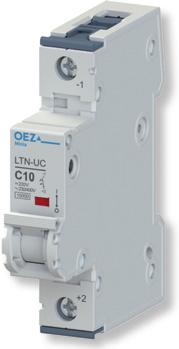
1 LFE Residual current circuit breakers RESIDUAL CURRENT CIRCUIT BREAKERS LFE Residual current circuit breakers with conditional shortcircuit current 6 ka. They react to sine-wave residual current (type AC). For protection: against dangerous contact with live parts (I Δn 30 ma) against dangerous contact with dead parts against fire or short-circuit in reduced insulation capacity of electrical equipment (I Δn 300 ma). Mounting/dismantling on/from U rails: The latches enable very quick mounting and dismantling by hand, without any tool needed. Operating ambient temperature is for all designs already from -25 C to +5 C. Equipped with device status indicator. Wide range of accessories - auxiliary and signal switches, undervoltage releases and shunt trips, interconnecting busbars etc. Possibility of locking and sealing in off or on position. Possibility of interconnection with circuit breakers LTE, LTN by means of interconnecting busbars up or down. N-pole of residual current circuit breakers in switching on it closes before and in switching off it opens after the other poles. Residual current circuit breaker are testing once per 6 months. LFE AC Residual current circuit breakers 2-pole, type AC Standard type for common use in building and housing installations up to 0 A, AC 230 V. Surge current resistance 250 A (8/20 μs) I Δn I n Type Order Number Weight Package [ma] [A] code of modules [kg] [pcs] 0 6 LFE AC OEZ: LFE AC OEZ: LFE AC OEZ: LFE AC OEZ: LFE AC OEZ: LFE AC OEZ: LFE AC OEZ: LFE AC Residual current circuit breakers -pole, type AC Standard type for common use in building and housing installations up to 80 A, AC 230/00 V. Surge current resistance 250 A (8/20 μs) I Δn I n Type Order Number Weight Package [ma] [A] code of modules [kg] [pcs] 25 LFE AC OEZ: LFE AC OEZ: LFE AC OEZ: LFE AC OEZ: LFE AC OEZ: LFE-0--00AC OEZ: LFE AC OEZ: LFE AC OEZ: LFE AC OEZ: LFE AC OEZ: LFE AC OEZ: LFE AC OEZ: LFE AC OEZ: S2L AS-50-S-AL0 Accessories Auxiliary and signal switches PS-LT, SS-LT page B36 Shunt trips SV-LT page B37 Undervoltage releases SP-LT page B37 Locking inserts OD-LT-VU02 page B39 Interconnecting busbars S2L, S2L+N, S3L+N, S3L-...FI-.. ), SL page B5 Terminal extension AS-50-S-AL0 page B7 ) For interconnection of the residual current circuit breaker with a series of circuit breakers where the series of circuit breakers needs to start from N-pole of the residual current circuit breaker. C SV-LT PS-LT OD-LT-VP0
2 LFE RESIDUAL CURRENT CIRCUIT BREAKERS LFE Residual current circuit breakers Minia Specifications Type LFE-..-2 LFE-..- Standards EN EN EN EN EN 653 EN 653 Approval marks Number of poles 2 Type AC AC Rated current I n 6, 25, 0 A 25, 0, 63, 80 A Rated residual current I Δn 0, 30, 00, 300 ma 30, 00, 300, 500 ma Rated operating voltage U e AC 230 V AC 230/00 V Min. operating voltage U min for I Δn = 30 ma AC 95 V AC 95 V (for test button function) U min for I Δn 30 ma AC 00 V AC 00 V Max. operating voltage U max AC 250 V AC 250/0 V Rated frequency f n 50 Hz 50 Hz Rated conditional short-circuit current I nc 6 ka (see table below) 6 ka (see table below) Rated making and breaking capacity I m 500 A 800 A Surge resistance 250 A 250 A Mechanical endurance > operating cycles > operating cycles Electrical endurance > operating cycles > operating cycles Degree of protection - with connected conductors IP20 IP20 Mounting on U rail according to EN 6075 type TH 35 TH 35 Connection Conductor Cu - rigid (solid, stranded) ) mm mm 2 Conductor Cu - flexible ) mm mm 2 Screw head type PZ2 PZ2 Torque Nm Nm Top or bottom connection top/bottom top/bottom Operating conditions Ambient temperature C C Working position arbitrary arbitrary Climatic resistance (EN ) 28 operating cycles 28 operating cycles (55 C, 95 % relative air humidity) (55 C, 95 % relative air humidity) ) For detailed connection of conductors see table on page C6. Protection of residual current circuit breakers A) Short-circuit protection In function principle, residual current circuit breaker is not possible to use for short-circuit protection. For circuit protection it is necessary to use a fuse or a circuit breaker, that cuts the short-circuited circuit safely off. The residual current circuit breaker must only withstand the through-going short-circuit current. The amplitude of the maximum through short-circuit current is defined as rated conditional short-circuit current I nc. The table below indicates the rated conditional shortcircuit current depending on the max. backup fuse and the circuit breaker. Rated conditional short-circuit current with backup fuse Design Rated current I n Max. backup Rated conditional short-circuit current LFE [A] fuse gg I nc [ka] 2-pole A 6 ka A 6 ka -pole A 6 ka B) Protection against overload Protection of the residual current circuit breakers against overload may be provided by fuses or circuit breakers subject to following conditions: - rated current of the fuse-link must be by one degree lower than rated current of the residual current circuit breaker I n of the fuse by one degree lower I n of the residual current circuit breaker - rated current of the circuit breaker must be equal or lower than the rated current of the residual current circuit breaker I n of the circuit breaker I n of the residual current circuit breaker. Rated conditional short-circuit current with backup circuit breaker Residual current Backup circuit breaker Rated conditional short-circuit current circuit breaker Type I n of the circuit breaker I nc [ka] LFE LTP, LTK, LTS, LVN I n MCB In RCCB 6 ka Powers losses P Design Rated Rated residual current I Δn [ma] LFN current I n [A] AC AC AC AC AC W/pole pole W/pole 0.6 W/pole 0.6 W/pole W/pole.6 W/pole.6 W/pole W/pole 0.7 W/pole 0.7 W/pole - -pole W/pole 2.0 W/pole 2.0 W/pole.8 W/pole W/pole 3.9 W/pole 3.9 W/pole 3.9 W/pole W/pole -. W/pole - C5
3 LFE Residual current circuit breakers RESIDUAL CURRENT CIRCUIT BREAKERS LFE Connection range Number of connected conductors Rigid conductor (solid, stranded) Conductor flexible with a sleeve Conductor flexible without a sleeve ) x conductor x ( ) mm 2 x ( ) mm 2 x ( 35) mm 2 2x conductor 2x (0.75 0) mm 2 2x (0.75 ) mm 2 2x ( ) mm 2 x conductor + interconnecting busbar x (0 25) mm 2 + interconnecting busbar x (6 6) mm 2 2) + interconnecting busbar - pin thickness max..5 mm pin thickness max..5 mm ) The conductor must be twisted before insertion to a terminal; individual conductor fibres must not stick out of the terminal. 2) In case of use of a sleeve without plastic neck: conductor x (6 25) mm 2. If more conductors are used they must be of the same type and cross-section. Dimensions LFE LFE Diagram LFE LFE-..- N 3 5 N 2 N 2 6 N Connection Standardní zapojení connection 2pólového of 2-pole residual proudového current chrániče circuit breaker LFE LFE Standardní connection zapojení pólového of -pole residual proudového current circuit chrániče breaker LFE LFE -pole pólový residual proudový current chránič circuit LFE breaker v LFE fázových in -phase obvodech circuits with s N-pólem N-pole -pole pólový residual proudový current chránič circuit LFE breaker ve LFE 3fázových in 3-phase obvodech circuits without bez N-pólu N-pole L N L L2 L3 N L N L L2 L3 N 3 5 N 3 5 N 3 5 N 2 N 2 6 N 2 6 N 2 6 N C6
 switches: MSO, MSN, AVN-DC.")

4 Miniature circuit breakers Auxiliary switches PS-LT-0200-TE Accessory to: miniature circuit breakers: LTP, LTK, LTS, LVN, LTN-UC residual current circuit breakers: LFN, LFE residual current circuit breakers with overcurrent protection: OLI, OLE (installation on OLI/OLE requires handle adapter OD-OL-NR0 see page B38 except for PS-LT-00-K) switches: MSO, MSN, AVN-DC. For signalling the position of contacts of the device in switching off by releases or manually, i.e. in switching off by overload, short-circuit, shunt trip or undervoltage release, residual current and manually by control lever. Mounting on the right side of the device. For the number of auxiliary switches connected to the device in combination with the other accessories see page B. Width 9 mm. Auxiliary switch function can be checked by test lever on the front side of the device (version PS-..-TE). Variant for switching small direct current voltages up to DC 30 V. They are suitable for application in SELV and PELV circuits - sufficient insulation is provided between the circuit breaker and the auxiliary switch. PS-LT-0200 Design Arrangement Type Order Number Weight Package of contacts ) code of modules [kg] [pcs] PS-LT-00 OEZ: Standard 20 PS-LT-2000 OEZ: PS-LT-0200 OEZ: PS-LT-00-TE OEZ: With test and reset lever 20 PS-LT-2000-TE OEZ: PS-LT-0200-TE OEZ: For small voltages standard PS-LT-00-MN OEZ: For small voltages with test lever PS-LT-00-MN-TE OEZ: With handle adapter OD-OL-NR0 2) PS-LT-00-K OEZ: ) Each digit indicates successively the number of make and break contacts. 2) PS-LT-00-K is a set for convenient ordering in installation on OLI/OLE. The other designs of the auxiliary switches installed on OLI/OLE require separate ordering of OD-OL-NR0. SS-LT-2000 SS-LT-2000-TE-RE Signal switches Accessory to: miniature circuit breakers: LTP, LTK, LTS, LVN, LTN-UC residual current circuit breakers: LFN, LFE residual current circuit breakers with overcurrent protection: OLI, OLE (installation on OLI/OLE requires handle adapter OD-OL-NR0 see page B38) switches: MSN. For position signalling of main contacts of the device in switching off by releases, i.e. in switching off by overload, short-circuit, shunt trip and undervoltage release or residual current. Mounting on the right side of the device. For the number of auxiliary switches connected to the device in combination with the other accessories see page B. Auxiliary switch function can be checked by test lever on the front side of the device (version SS-..-TE). Signal switch can be reset by means of the red reset lever on the front side of the device without switching the device on by the control lever (version SS-..-RE). They are suitable for application in SELV and PELV circuits - sufficient insulation is provided between the circuit breaker and the signal switch. Reaction in switching off by releases: in switching off by releases the make/break contact will break/make for details see the table on page B. Design Arrangement Type Order Number Weight Package of contacts ) code of modules [kg] [pcs] SS-LT-00 OEZ: Standard 20 SS-LT-2000 OEZ: SS-LT-0200 OEZ: SS-LT-00-TE-RE OEZ: With test and reset lever 20 SS-LT-2000-TE-RE OEZ: SS-LT-0200-TE-RE OEZ: ) Each digit indicates successively the number of make and break contacts. B36
5 ture circuit breakers Minia Shunt trips Accessory to: miniature circuit breakers: LTS, LVN, LTN-UC residual current circuit breakers: LFN, LFE residual current circuit breakers with overcurrent protection: OLI, OLE (installation on OLI/OLE requires handle adapter OD-OL-NR0 see page B38) switches: MSN. They are used for device switching off by applied voltage. Mounting: on the right side of the device one shunt trip can be connected to one device in combination with the other accessories - see page B. SV-LT-X00 Rated voltage Type Order Number Weight Package U c code of modules [kg] [pcs] AC/DC 2 60 V SV-LT-X060 OEZ: AC 0 5 V / DC V SV-LT-X00 OEZ: Undervoltage releases Accessory to: miniature circuit breakers: LTS, LVN, LTN-UC residual current circuit breakers: LFN, LFE residual current circuit breakers with overcurrent protection: OLI, OLE (installation on OLI/OLE requires handle adapter OD-OL-NR0 see page B38) switches: MSN. They are used for tripping the device at loss of voltage as well as at gradual decrease of voltage. They are used for elimination of closing of circuit breaker if voltage is lower than 35 % U c (switching is possible at voltage higher than 85 % U c ). They are often used for protection against device restart following mains failure. Mounting: on the right side of the device one undervoltage release can be connected to one device in combination with the other accessories - see page B. SP-LT-A230 Rated voltage Arrangement Type Order Number Weight Package U c of contacts ) code of modules [kg] [pcs] AC 230 V - SP-LT-A230 OEZ: SP-LT-A OEZ: DC 2 V - SP-LT-D02 OEZ: SP-LT-D OEZ: DC 0 V - SP-LT-D0 OEZ: SP-LT-D OEZ: ) Each digit indicates successively the number of make and break contacts. B37

 undervoltage releases (SP-LT) shunt trips (SV-LT).")

![Type Order Weight Package code [kg] [pcs] OD-OL-NR0 OEZ:38270 0.](/docs-images/80/82203904/images/6-4.jpg "02 5 Example of installation 2 OD-OL-NR0 3 3 5 5 6 5 Locking insert OD-LT-VU0")


6 Miniature circuit breakers OD-OL-NR0 Handle adapter OD-OL-NR0 Accessory to: OLI, OLE. It enables installation of the following accessories on residual current circuit breakers with overcurrent protection OLI, OLE auxiliary switches (PS-LT) signal switches (SS-LT) undervoltage releases (SP-LT) shunt trips (SV-LT). Special auxiliary switch PS-LT-00-K contains the handle adapter OD-OL-NR0. So it is not necessary to order it separately. Type Order Weight Package code [kg] [pcs] OD-OL-NR0 OEZ: Example of installation 2 OD-OL-NR Locking insert OD-LT-VU0 Accessory to: miniature circuit breakers: LTK, LVN, LTN-UC residual current circuit breakers: OLI, OLE switches: MSN, AVN-DC. For safe locking of the control lever in off or on position. The protective function of the devices is functional even in locked position. Maximum diameter of lock rod - 3 mm. The lock is not included in the package. Type Order Weight Package code [kg] [pcs] OD-LT-VU0 OEZ: OD-LT-VU0 B38


![Type Order Weight Package code [kg] [pcs] OD-LT-VU02](/docs-images/80/82203904/images/7-9.jpg "OEZ:2325 0.")

7 ture circuit breakers Minia OD-LT-VU02 Locking insert OD-LT-VU02 Accessory to: miniature circuit breakers: LTP, LTS residual current circuit breakers: LFN, LFE switches: MSO. For safe locking of the control lever in off or on position. The protective function of the devices is functional even in locked position. Maximum diameter of lock rod - 6 mm. The lock is not included in the package. In installation it is necessary to press the fixing springs of the insert by two fingers against each other, and then slide them in the holes in the circuit breaker. In case of pressing the insert against the circuit breaker body a part of the plastic cover could break off! Type Order Weight Package code [kg] [pcs] OD-LT-VU02 OEZ: Sealing insert OD-LT-VP0 Accessory to: miniature circuit breakers: LTP, LTS, LVN, LTN-UC residual current circuit breakers: OLI, OLE switches: MSO, MSN, AVN-DC. For covering and sealing of terminal screws. OD-LT-VP0 Type Order Weight Package code [kg] [pcs] OD-LT-VP0 OEZ: B39
8 Miniature circuit breakers Specifications of auxiliary and signal switches DC-3 2) Type PS-LT PS-LT-00-MN SS-LT PS-LT-00-MN-TE Standards EN EN EN 6209 EN 6209 Approval marks Arrangement of contacts ), 20, 02, 20, 02 Rated operating voltage/current U e /I e 00 V 2 A - AC V 6 A - AC- 00 V 2 A V 6 A - 0 V A/0.75 A - 60 V 3 A/.5 A V A/0.5 A - 2 V 6 A/3 A - Max. voltage/current - DC 30 V / 00 ma Min. voltage/current 2 V / 50 ma DC 5 V / ma Backup protection - fuse / miniature circuit breaker 6 A gg / 6 A characteristic B, C 6 A gg / 6 A characteristic B, C Mechanical endurance operating cycles operating cycles Electrical endurance at I e operating cycles operating cycles Degree of protection IP20 IP20 Connection Conductor Cu rigid (solid, stranded) mm mm 2 Conductor Cu flexible mm mm 2 Torque 0.5 Nm 0,5 Nm Connection top/bottom top/bottom Operating conditions Ambient temperature C C Working position arbitrary arbitrary Climatic resistance according to IEC operating cycles 28 operating cycles Shocks (EN ) m/s 2 50 in ms half-sine pulse 50 in ms half-sine pulse Vibration resistance according to IEC m/s 2 50 at 0 50 Hz 50 at 0 50 Hz ) Each digit indicates successively the number of make and break contacts. 2) Value according to EN 6209 / according to EN Function of signal switch SS-LT Circuit breaker contact state The state of the MAKE signal contact SS-LT- * Initial position - contacts open switched off Switching on manually - contacts closed switched on Switching off manually - contacts open switched on Switching off by release - contacts open switched off * The break contact works in opposite way. B0
9 ture circuit breakers Minia Specifications of shunt trips and undervoltage releases Type SV-LT SP-LT Standards EN EN Approval marks Mounting on the right side of the device on the right side of the device Degree of protection IP20 IP20 Control circuit coil Rated voltage U c AC/DC 2 60 V AC 230 V AC 0 5 V / DC V DC 2, 0 V Range of rated voltage 0.7. U c U c Voltage range for switching off - < U c Rated frequency f n 50/60 Hz 50/60 Hz Backup protection - fuse / miniature circuit breaker 6 A gg / 6 A characteristic B, C 6 A gg / 6 A characteristic B, C The length of impulse necessary for device switching off 5 ms Contact Arrangement of contacts ) - 20 Rated operating voltage/current U e /I e AC V / 6 A Min. voltage/current - 2 V / 50 ma Backup protection - fuse / miniature circuit breaker - 6 A gg / 6 A characteristic B, C Connection Conductor Cu rigid (solid, stranded) mm mm 2 Conductor Cu flexible mm mm 2 Torque 0.8 Nm 0.8 Nm Connection top/bottom top/bottom Operating conditions Mechanical endurance operating cycles operating cycles Electrical endurance operating cycles operating cycles Ambient temperature C C Working position arbitrary arbitrary Climatic resistance according to IEC operating cycles 28 operating cycles Shocks (EN ) m/s 2 50 in ms half-sine pulse 50 in ms half-sine pulse Vibration resistance according to IEC m/s 2 50 at 0 50 Hz 50 at 0 50 Hz ) Each digit indicates successively the number of make and break contacts. B
10 Miniature circuit breakers Dimensions PS-LT, SS-LT 73.3 SV-LT SP-LT 73.3 C D C2 D LTK, MSN, OLI, OLE, AVN-DC, LTN-UC, LVN + OD-LT-VU0 + OD-LT-VP0 OD-LT-VP0 OD-LT-VU LTP, LTS, MSO + OD-LT-VU B2
11 ture circuit breakers Minia Diagram PS-LT-00, PS-LT-00-K PS-LT-2000 PS-LT-0200 SS-LT-00 SS-LT-2000 SS-LT PS-LT-00-TE PS-LT-2000-TE PS-LT-0200-TE SS-LT-00-TE-RE SS-LT-2000-TE-RE SS-LT-0200-TE-RE TEST TEST TEST TEST TEST TEST SV-LT-.. SP-LT SP-LT C C2 D A 3 23 U< U< D2 D2 2 Installation of auxiliary switch, shunt trips or undervoltage releases For installation of an auxiliary switch, shunt trip or undervoltage releases on a circuit breaker, residual current circuit breaker or switch, the same procedure shall apply as described on the example of installation of the auxiliary switch on the circuit breaker in the following points.. In mounting the levers of auxiliary switch and of the circuit breaker are in ON position. 2. Tilt both fixing springs of the auxiliary switch to the right so that they do not get between the auxiliary switch and circuit breaker in installation. 3. Slide the auxiliary switch onto the circuit breaker from the right.. Lock the fixing springs in the circuit breaker body so that the auxiliary switch cannot release. 5. Check correct function by switching B3


12 Miniature circuit breakers Combination of accessories LTP, LTK Any combination of PS-LT and SS-LT, max. 2 units Any combination of PS-LT and SS-LT, max. 2 units or LTS, LFE, LFN, OLE, OLI* SV-LT * Installation of accessories on OLI/OLE requires handle adapter OD-OL-NR0 see page B38. SP-LT Any combination of PS-LT and SS-LT, max. 2 units Any combination of PS-LT and SS-LT, max. 3 units or LTN-UC, LVN, MSN* SV-LT * Installation of signal switches SS-LT on the MSN switch, only with SP-LT or SV-LT SP-LT Any combination of PS-LT and SS-LT, max. 3 units B MSO, AVN-DC PS-LT max. 3 units
 I Δn.")

13 Residual current circuit breakers Minia BASIC TERMS, SYMBOLS AND BREAK TIMES Rated residual operating current I Δn is the value of residual current I Δn specified by the manufacturer, at which the residual current circuit breaker must switch out under specified conditions. Alternating residual current must by cut off by the residual current circuit breaker within (0.5 ) I Δn. Rated current I n is the value of current specified by the manufacturer, which can be transferred by the residual current circuit breaker continuously. So the current I n can pass through the contacts for an unlimited time. Therefore it is, for instance, possible to use a residual current circuit breaker with I n = 25 A in the circuit with max. current up to 25 A. For protection against overload of the residual current circuit breakers LFE, LFN, OFI it is recommended to use the circuit breakers LTE, LTN, LVN with rated curren I n MCB I n RCCB. Rated operating voltage U e is the voltage the residual current circuit breaker is to be connected to and which properties are related to. The connected voltage has no effect on the device function but on the function of the test circuit and isolation properties. Rated frequency f n is the frequency the residual current circuit breaker is designed for and at which it works correctly under stated conditions. Majority of residual current circuit breakers are designed for f n = 50 to 60 Hz. As the residual current circuit breaker function is based on the induction principle, the residual current behaviour and frequency show an effect upon tripping. When using a device designed for 50/60 Hz in a network with a different frequency, the user must count on a change of the tripping threshold i.e. a change of I Δn. Rated conditional short-circuit current I nc shortcircuit strength. The function and design principle does not allow to use the residual current circuit breaker for protection against short-circuit. For circuit protection it is necessary to use a circuit breaker or a fuse. These elements cut the short-circuited circuit safely off. The residual current circuit breaker must only withstand the through-going short-circuit current. The amplitude of the maximum through current is defined as rated conditional short-circuit current I nc. The short-circuit strength is then expressed by the current I nc. For example, on the rating plate I nc = 0 ka is expressed by the following symbol: Ambient temperature T for the residual current circuit breakers is (-5 +0) C according to almost all international standards. Some residual current circuit breakers work in an extended range (-25 +0) C. This possibility is identified by the following symbol on the rating plate: -25 Residual current circuit breaker type AC rreacts to sine-wave residual current it is used in conventional AC networks Residual current circuit breaker type A eacts to sine-wave alternating and pulsating direct residual currents it is used in conventional AC networks and the networks with phase power regulation etc. Residual current circuit breaker type G special residual current circuit breaker reducing the number of undesirable cut-offs. It is mainly installed before the devices causing short-time (up to 0 ms) stray currents. Identification: G Surge resistance: 3 ka (8/20 μs) Release delay: 0 ms G Residual current circuit breaker type S special residual current circuit breaker, which is mainly intended for selective switching of residual current circuit breakers and reduction of undesirable cut-offs. It is installed before the devices causing short-time (up to 0 ms) stray currents. Identification: S Surge resistance: 5 ka (8/20 μs) Release delay: 0 ms S Selective (discriminating) switching means that if the residual current circuit breakers are connected in series, only the device in which circuit a failure occurs will cut off the current. More specifically, only the device in which the tripping residual current appears due to a failure in the protected circuit will turn off the current. The advantage consists in maintaining the power supply in the other circuits not affected by the failure. Such function of the protected circuit is achieved by connection of the selective residual current circuit breaker (see Fig. ) before the standard or G type residual current circuit breaker, with the following ratio of rated residual currents: I ΔnS I Δn -,G I Δn S 3 x I Δn -,G rated residual operating current of the selective residual current circuit breaker rated residual operating current of standard or G type residual current circuit breaker he main reason of selective disconnecting of circuits is higher time delay of the selective residual current circuit breakers in tripping (compared to standard or G type ones). load I ΔnS I = 0. A Δn- I = 0.03 A ΔnG load Fig.. Simplified example of selective connection of residual current circuit breakers Residual current circuit breaker with overcurrent protection the device is a combination of residual current circuit breaker and circuit breaker with 2-module width it saves the space in the switchboard compared to conventional connection of two separate devices (3 modules). This eliminates the problem of backup protection and interconnection. The disadvantage of such a design compared to conventional one is that it is not possible to identify whether the tripping was actuated by the residual current circuit breaker or by the circuit breaker. Min. time delay and break times of the residual current circuit breakers Type of residual current circuit breakers standard type G type S Min. time delay T v s Break times t at I Δn s t t t 0.5 (according to EN 6008-) at 2I Δn s t t t 0.2 at 5I Δn s t t t 0.5 at 500 A s t t t 0.5 note no bottom limits of the break time value 0.0 s is not given by standard break times are valid for the residual current circuit breaker with I n 25 A and I Δn > 0.03 A C27

14 Residual current circuit breakers BASIC TERMS, SYMBOLS AND BREAK TIMES Examples of characteristics The characteristics indicated below are based on requirements of EN and valid for: standard residual current circuit breakers and residual current circuit breakers with G type delay with I Δn = 30 ma residual current circuit breakers with S type delay with I Δn = 00 ma Break time [ms] S Selective (inactivity time min. 0 ms) 50 0 G with delay (inactivity time min. 0 ms) Standard (undelayed) Valid for: I Δn = 30 ma 0.05 G Residual current I Δ [A] I Δn = 00 ma S I Δn 2I Δn 5I Δn I Δn 2I Δn 5I Δn C28
RESIDUAL CURRENT CIRCUIT BREAKERS WITH OVERCURRENT PROTECTION OLE
 OLE Residual current circuit breakers RESIDUAL CURRENT CIRCUIT BREAKERS WITH OVERCURRENT PROTECTION OLE OLE-10B-1N-030AC The device is a combination of residual current circuit breaker and circuit breaker.
RESIDUAL CURRENT CIRCUIT BREAKERS WITH OVERCURRENT PROTECTION OLFE (6 ka)
") Residual current circuit breakers MINIA RESIDUAL CURRENT CIRCUIT BREAKERS WITH OVERCURRENT PROTECTION OLFE ( ka) The device is a combination of residual current circuit breaker and circuit breaker For
Residual current circuit breakers MINIA RESIDUAL CURRENT CIRCUIT BREAKERS WITH OVERCURRENT PROTECTION OLFE ( ka) The device is a combination of residual current circuit breaker and circuit breaker For
RESIDUAL CURRENT CIRCUIT BREAKERS OFI (10 ka)
") Residual current circuit breakers RESIDUAL CURRENT CIRCUIT BREAKERS OFI (10 ka) They react to both alternating sine-wave residual current and pulsating direct current (type A) For protection: against accidental
Residual current circuit breakers RESIDUAL CURRENT CIRCUIT BREAKERS OFI (10 ka) They react to both alternating sine-wave residual current and pulsating direct current (type A) For protection: against accidental
RESIDUAL CURRENT CIRCUIT BREAKERS OFE (6 ka)
") Residual current circuit breakers RESIDUAL CURRENT CIRCUIT BREAKERS OFE ( ka) Standard type for common use in building and housing installations up to 3 A, 230/400 V a.c. They react to alternating sine-wave
Residual current circuit breakers RESIDUAL CURRENT CIRCUIT BREAKERS OFE ( ka) Standard type for common use in building and housing installations up to 3 A, 230/400 V a.c. They react to alternating sine-wave
Basic function. Rated current. Appropriate for three-phase motors of output 2) [kw] I n. = 400 V a.c. 2) Appropriate for three-phase motors
![Basic function. Rated current. Appropriate for three-phase motors of output 2) [kw] I n. = 400 V a.c. 2) Appropriate for three-phase motors](/thumbs/74/70162763.jpg "Basic function. Rated current. Appropriate for three-phase motors of output 2) [kw] I n. = 400 V a.c. 2) Appropriate for three-phase motors") MOTOR STARTERS SM Basic function Switching and protection of motors up to A Protection against short-circuit and protection against overload The device responds to phase failure The device is provided
MOTOR STARTERS SM Basic function Switching and protection of motors up to A Protection against short-circuit and protection against overload The device responds to phase failure The device is provided
Devices for switching and control
 Devices for switching and control WWWOEZCOM Motor starters MOTOR STARTERS SM Basic function Switching and protection of motors up to 2 A Protection against short-circuit and protection against overload
Varius SUMMARY OF MODELS
 Varius SUMMARY OF MODELS Type FH00 FH1 FH2 FH3 LTL4a Rated operating current I e 160 A 160 A 250 A 400 A 630 A 1 600 A Rated operating voltage AC/DC U e 690 V 690 V 690 V 690 V 690 V 690 V Size 000 00
max pole for t=15 ms
 Types RI 61 RI 61N RI 61J RI 62 RI 62J RI 63 RI 63N RI 64 single-pole single-pole + neutral pole single-pole (for DC circuits) two-pole two-pole (for DC circuits) three-pole three-pole + neutral pole three-pole
Varius SUMMARY OF MODELS
 SUMMARY OF MODELS Type 10 14 22 OPT22/OPT20 OPVF10 Rated operating current I e / Rated current I n 32 A / - 63 A / - 125 A / - 63 A / - - / 30 A Rated operating voltage U e / Rated voltage U n AC 690 V
W Datasheet: Residual current circuit breaker, series PRIORI, 10kA, Typ B
 W Datasheet: Residual current circuit breaker, series PRIORI, 10kA, Typ B W SCHRACK-INFO All-current sensitive RCCB ( type B, B+ and Bfq) B+ types also meet the requirements of superior fire-protection
MOULDED CASE CIRCUIT BREAKERS BC160N
 D MOULDED CASE CIRCUIT BREAKERS BC160N D BC160N COMMERCIAL INFORMATION Circuit breakers...d4 Switch-disconnectors...D5 Connecting sets......d6 Mounting sets......d6 Switches...D7 Shunt trips...d7 Undervoltage
Varius SUMMARY OF MODELS
 SUMMARY OF MODELS FH000 FH00 FH FH2 FH LTL4a Rated operating current I e 60 A 60 A 250 A 400 A 60 A 600 A Rated operating voltage AC/DC U e 690 V 690 V 690 V 690 V 690 V 690 V Size 000 00 2 4a Fuse-link
Modeion MOULDED CASE CIRCUIT BREAKERS BL1600S
 H MOULDED CASE CIRCUIT BREAKERS BL6S H BL6S COMMERCIAL INFORMATION Switching units, withdrawable device...h4 Overcurrent releases...h5 Signalling units...h5 Residual current monitor...h6 Current transformers
Residual Current Protective Devices / Arc Fault Detection Devices (AFDDs)
") Introduction Overview Devices Page Application Standards Used in / Personnel, material and fire protection, as well as protection against direct contact. SIGRES with active condensation protection for
Introduction Overview Devices Page Application Standards Used in / Personnel, material and fire protection, as well as protection against direct contact. SIGRES with active condensation protection for
Technical Data Accessories MCBs Ex9B.
 Auxiliary and signal contact units AX31, A31, AX31 General parameters With one circuit breaker Ex9B., it can be used up to three contact units with single CO contact or up to two contact units with 2 CO
IP20 degree of protection; IP40 degree of protection after installation in a distribution box
 RI 50 RI 50 is used for the protection of installations and devices (overload and short circuit), and as a disconnector in case of electric shock Simple and quick fixing to a 35 mm mounting rail in accordance
Page. Circuit-Breakers M4 2 for motor protection. Auxiliary contacts 3 Signalling switch Auxiliary releases
 Circuit Breakers M4 Page Circuit-Breakers M4 2 for motor protection Auxiliary contacts 3 Signalling switch Auxiliary releases Insulated 3-pole busbar system 4 Terminal block DIN-rail adapters 5 Busbar
Overcurrent releases - description, specifications, characteristics specifications specifications description...
 BA5*37 COMMERCIAL INFORMATION Type designation specification for ordering...68 (design and circuit breaker and switch-disconnector accessories selection, circuit breaker rated current selection) Connecting
schneider-electric.com/sg K60 Circuit Breakers The affordable way to stay safe from electrocution and electrical overloads schneider-electric.
 K0 Circuit Breakers The affordable way to stay safe from electrocution and electrical overloads Overview K0 Circuit Breaker Technical Specification MCB RCCB K0 Circuit Breaker K0N K0H ID K Number of poles
Miniature Circuit-Breakers (MCBs)
") Product Overview Miniature Circuit-Breakers (MCBs) Design Tripping characteristics Rated current I n Rated breaking capacity Power supply company product range 5SP3 E 16 - A Standard product range 5SQ2
Product Overview Miniature Circuit-Breakers (MCBs) Design Tripping characteristics Rated current I n Rated breaking capacity Power supply company product range 5SP3 E 16 - A Standard product range 5SQ2
The breakers offer thermal-magnetic trip protection according to Z and K characteristics.
 Series High Performance Circuit Breakers Description The high performance MCB offers a compact solution to circuit protection. The devices are DIN rail mounted. The is available with application-specific
Residual current devices
 Residual devices FH00 Plus of range /30 Technical features table /3 Ordering information /34 Technical details /37 DS01 and DS0C Plus of range /38 Technical features table /40 Ordering information DS01
Miniature Circuit Breaker
 Introduction - Miniature Circuit Breaker (MCB) SALIENT FEATURES SALIENT FEATURES Standards MCBs conform to the latest standard IS 8828: 1996/IEC: 898 1995 Mid-Trip Position The Mid trip position of the
COMMERCIAL INFORMATION TECHNICAL INFORMATION BA511*33
 BA511*33 COMMERCIAL INFORMATION Type designation specification for ordering...146 (design and circuit breaker and switch-disconnector accessories selection, circuit breaker rated current selection) Connecting
Protection Equipment
 Protection Equipment Price Groups 101, 102, 121, 131, 143 /2 Introduction Motor Starter Protectors/ Circuit Breakers SIRIUS 3RV2 Motor Starter Protectors up to 40 A new /7 General data /13 For motor protection
Miniature Circuit-Breakers (MCBs)
") Product overview Miniature Circuit-Breakers (MCBs) Design Tripping characteristic Rated currents I n Rated breaking capacity Power supply company product range 5SP3 E 16 - A Standard product range 5SX2
Product overview Miniature Circuit-Breakers (MCBs) Design Tripping characteristic Rated currents I n Rated breaking capacity Power supply company product range 5SP3 E 16 - A Standard product range 5SX2
Electronic circuit breaker EBU10-T
 Description The electronic circuit protector type EBU10-T (Electronic Breaker Unit) provides selective overcurrent protection in AC 230 V UPS systems. It consists of an MCB approved for short circuit interruptions
and other modular devices for low voltage installation
 Technical catalogue System and other modular devices for low voltage installation 2CSC400002D0204 SUMMARY Introduction Miniature Circuit-Breakers Residual Current Devices Auxiliary elements and accessories
3VU13, 3VU16 Circuit-Breakers
 3VU3, 3VU6 Circuit-Breakers Description The 3VU3, 3VU6 circuit-breakers are compact circuit-breakers for currents up to 80 A which operate according to the current limiting principle. The devices are used
MOULDED CASE CIRCUIT BREAKERS BH630N, BH630S
 MOULDED CASE CIRCUIT BREAKERS BH6N, BH6S F BH6N, BH6S COMMERCIAL INFORMATION Switching units, withdrawable device, plug-in device...f4 Switch-disconnector unit...f6 Connecting sets...f7 Mounting sets...f9
Connecting sets CS-FS CS-FS123-WD. Connecting space covers OD-FS00-.. OD-FS123-KP. Adapter for parallel outlet - HP-SE/K
 Varius SUMMARY OF MODELS OF FUSE-RAILS Type FSR00 FSR1 FSR2 FSR3 Rated operating current I e 160 A 250 A 400 A 630 A Rated operating voltage AC/DC U e 690 V 690 V 690 V 690 V Size 00 1 2 3 Busbar spacing
MS25, MST25, MS20, MST20
 Motor protection switches MS25, MST25, MS20, MST20 Versions: - MS25 with thermal and magnetic releases - MST25 with a thermal release - MS20 - with thermal and magnetic releases for single-phase consumers
FUSOMAT Visible breaking and tripping fuse switches from 250 to 1250 A
 Fuse protection The solution for > Motor load break > Protection of industrial cabinet > Electrical distribution fusom_063_b_1_cat Strong points > Tripping upon overload > High breaking capacity > Improved
DX³ RCCBs - ID 4P up to 100 A
 87045 LIMOGES Cedex Telephone number: +33 (0)5 55 06 87 87 Fax: +33 (0)5 55 06 88 88 DX³ s - ID CONTENTS PAGE 1. Description, use... 1 2. Range... 1 3. Overall dimensions... 1 4. Preparation - Connection...
Thermal-magnetic Miniature Circuit Breaker 4230-T...
 Thermal-magnetic Miniature Circuit Breaker 420-T... Description Single pole and multipole thermal-magnetic miniature circuit breakers (MCBs) in accordance with EN 60947-2, UL 077 and UL 489 for DIN rail
Selective main circuit breakers S 750 series Technical Data
 Selective main circuit breakers S 750 series Technical Data When connecting aluminium conductors ( 4 mm 2 ) ensure that the contact surfaces of the conductors are cleaned, brushed and treated with grease.
Circuit-Breakers M4 166 for motor protection. Auxiliary contacts 167 Signalling switch Auxiliary releases
 Index Page Circuit-Breakers M4 166 for motor protection Auxiliary contacts 167 Signalling switch Auxiliary releases Insulated 3-pole busbar system 168 Terminal block DIN-rail adapters 169 Busbar adapters
Low Voltage A GE Power Controls Company. General catalogue
 Low Voltage A GE Power Controls Company General catalogue this is a blanc page Miniature circuit breakers A Miniature circuit breakers AC miniature circuit breakers Benefits of the new MCB s A 3 The AEG
MOULDED CASE CIRCUIT BREAKERS BL1600S
 H MOULDED CASE CIRCUIT BREAKERS BL6S H BL6S COMMERCIAL INFORMATION Switching units, withdrawable device, plug-in device...h4 Overcurrent releases...h Signalling units...h Connecting sets...h6 Switches...H8
TX³ RCCBs 2P up to 100 A
 87045 LIMOGES Cedex Telephone number: +33 (0)5 55 06 87 87 Fax: +33 (0)5 55 06 88 88 TX³ RCCBs CONTENTS PAGE 1. Description, use... 1 2. Range... 1 3. Overall dimensions... 1 4. Preparation - Connection...
Miniature circuit breakers
 Miniature circuit breakers Miniature circuit breaker ETIMAT 6 Rated short-circuit capacity Rated current Tripping characteristic 6 ka 6-63 A B, C 1-pole 6 230/400 002111512 002141512 112 12/108 10 230/400
Thermal-magnetic Miniature Circuit Breaker 4230-T...
 Thermal-magnetic Miniature Circuit Breaker 40-T... Description Single pole and multipole thermal-magnetic miniature circuit breakers (MCBs) in accordance with EN 60947-, UL 1077 and UL 489 for DIN rail
Cat. N (s) : /65/66/83/84, /94/95/96/99, /01/02/06/07/11/12/13/14. Pollution degree : C / + 40 C. .
 : /65/66/83/84, /94/95/96/99, /01/02/06/07/11/12/13/14. Pollution degree : C / + 40 C. .") 87045 LIMOGES Cedex Telephone : (+33) 05 55 06 87 87 Fax : (+ 33) 05 55 06 88 88 R.C.C.B. s 0090 00/01/02/06/07/11/12/13/14 0/01/02/06/07/11/12/13/14/18/19/23/24/25/26/ /18/19/23/24/25/26/45/46 45/46 0090
87045 LIMOGES Cedex Telephone : (+33) 05 55 06 87 87 Fax : (+ 33) 05 55 06 88 88 R.C.C.B. s 0090 00/01/02/06/07/11/12/13/14 0/01/02/06/07/11/12/13/14/18/19/23/24/25/26/ /18/19/23/24/25/26/45/46 45/46 0090
Technical Data. Miniature circuit-breakers for branch circuit protection according to UL 489, CSA C 22.2 No. 5
 Technical Data Miniature circuit-breakers for branch circuit protection according to UL 489, CSA C 22.2 No. 5 When connecting aluminum conductors, ensure that the contact surfaces of the conductors are
Characteristics of LV circuit breakers Releases, tripping curves, and limitation
 Characteristics of LV circuit breakers Releases, tripping curves, and limitation Make, Withstand & Break Currents A circuit breaker is both a circuit-breaking device that can make, withstand and break
Technical data. Miniature Circuit Breakers. System pro M. System pro M
 Technical data System pro M System pro M 1 Prior to connection of aluminium conductors ensure that their contact points are cleaned, brushed and coated with grease. The contact terminals must be tighten
Index. Manual Motor Starters 1. Auxiliary Contact Blocks 1. Trip Alarm Auxiliary 1. Switch. Shunt Release 1. Under-voltage Release 2.
 Index Index Page Manual Motor Starters 1 Auxiliary Contact Blocks 1 Trip Alarm Auxiliary 1 Switch Shunt Release 1 Under-voltage Release 2 Accessories 2 Busbar Connectors 2 Enclosures 2 Leistung, kw C mv
D509E. Manual Motor - Starters
 D509E Manual Motor - Starters Index Page Manual Motors Starters 182 Auxilliary Contact Blocks 182 Trip Alarm Aux. Switch 182 Shunt Release 182 Under-voltage Release 183 Accessories 183 Busbar Connectors
MCCB Accessories to suit AF
 MCCB s MCCB Accessories to suit 125-630AF Accessory fitting combinations INTERNAL General purpose types Micro-switch types Auxiliary Heavy duty types Bridge -contact types Auxiliary Shunt UVT Internal
TeSys contactors. Use in category DC-1 (resistive loads; time constant L/R y 1 ms) Rated operational current Ie. to be wired in series
 Rated operational current Ie. to be wired in series") Selection 3-pole shockproof contactors FG d.c. supply Selection guide for utilisation categories DC-1 to DC-5 Use in category DC-1 (resistive loads; time constant L/R y 1 ms) Rated operational current
Selection 3-pole shockproof contactors FG d.c. supply Selection guide for utilisation categories DC-1 to DC-5 Use in category DC-1 (resistive loads; time constant L/R y 1 ms) Rated operational current
Instantaneous tripping TYPE B, C, D TYPE B, C TYPE B, C, D TYPE B, C IEC RCCB TYPE C IEC61008 RCBO 25, 40, 63A. IEC61009 Isolating Switch
 Features (1) All models fully comply with IEC regulations (2) Units can be mounted on a standard 35mm IEC rail (3) Residual current circuit breakers use an original Mitsubishi Electric IC securing reliable
Modular contactor for installation into distribution boards
 Modular contactor for installation into distribution boards Description Modular contactors are used for installation in consumer units in dwellings, business premises, hotels, hospitals, shopping centres,
Phase + Neutral, neutral on left side
 87045 LIMOGES Cedex Téléphone : 05 55 06 87 87 Télécopie : 05 55 06 88 88 DX 3 MCB 10000 A / 16 ka CONTENTS PAGE 1. Description, use...1 2. Range...1 3. Overall dimensions...1 4. Preparation - Connection...1
W DATA SHEET: COMBINED FAULT-CURRENT PROTECTIVE SWITCH, SERIES BOLF, 3P+N
 W DATA SHEET: COMBINED FAULT-CURRENT PROTECTIVE SWITCH, SERIES BOLF, 3P+N W SCHRACK-INFO Typ A (pulse) Connection on both sides are possible Tripping independent of line voltage Additional connection capability
TM12 Series CIRCUIT BREAKERS FOR EQUIPMENT. Thermal magnetic release Positively trip-free Reset or manual actuation
 CIRCUIT BREAKERS FOR EQUIPMENT TM Series Thermal magnetic release Positively trip-free Reset or manual actuation The TM circuit breaker for equipment (CBE) is a single pole, thermal-magnetically operated
MOULDED CASE CIRCUIT BREAKERS BC160N
 D MOULDED CASE CIRCUIT BREAKERS BC6N Tento výrobek byl vyvinut za finanční podpory ze státních fondů prostřednictvím Ministerstva průmyslu a obchodu. D BC6N COMMERCIAL INFORMATION Circuit breakers...d4
MINIATURE CIRCUIT BREAKER
 Technical Article MINIATURE CIRCUIT BREAKER T 146 PURCHASE he Spaceage MCB protects wires and cables automatically against overload and short-circuits in domestic, commercial and industrial installations.
COMBINATION CIRCUIT BREAKERS RCBO
 COMBINATION CIRCUIT BREAKERS RCBO W COMBINED MCB AND RCCB, SERIES BOLF W CONTACT POSITION INDICATOR 108 TYPE EAN CODE FOR QUICK ORDERING TRIP INDICATOR WHITE/BLUE CONTACT POSITION INDICATOR RED/GREEN W
All round protection guaranteed
 s With SLR ll round protection guaranteed Betagard MCB 5SL Inspiring Safety nswers for infrastructure. Overview s a culture Siemens has always endeavoured to introduce innovative products worldwide. The
DX 3 MCBs. Choice of DX 3 MCBs for capacitor banks. Technical data
 Specifications IS/IEC 60898-1 2002 Number of poles SP, SPN, DP, TP, TPN, FP Characteristics C & D Curve Breaking capacity 10 ka 0.5 A to 63 A as per IS/IEC 60898-1 2002 16 ka for 0.5 A to 25 A as per IEC
Phase + Neutral, neutral on right side
 87045 LIMOGES Cedex Telephone number: +33 5 55 06 87 87 Fax: +33 5 55 06 88 88 DX 3 MCB 6000 A / 10 ka Cat.. N (s): 4 074 67 / 68 / 69 / 70 / 71 / 72 / 73 / 74 / 75 / 76 / 77 / 78 / 79 ; 4 077 33 / 34
DX³ 4-pole RCBO 6000 A/10 ka
 87045 LIMOGES Cedex Telephone number: +33 (0)5 55 06 87 87 Fax: +33 (0)5 55 06 88 88 DX³ 4-pole RCBO CONTENTS PAGE 1. Description, use... 1 2. Range... 1 3. Overall dimensions... 1 4. Preparation - Connection...
Protection Equipment. 5/2 Introduction
 Protection Equipment /2 Introduction SIRIUS 3RV2 Motor Starter Protectors/ Circuit Breakers up to 40 A /6 General data /12 For motor protection /14 For motor protection with overload relay function /1
Electronic Circuit Breaker ESS20-0..
 Electronic Circuit Breaker ES-0.. Description Electronic circuit breaker type ES-0.. is designed to ensure selective disconnection of individual loads in systems which are powered by a DC 4 V switch-mode
Data sheet. CI-TI TM Contactors and Motor Starters Circuit Breakers CTI B1427
 Data sheet CI-TI TM Contactors and Motor Starters Circuit Breakers November 2002 DKACT.PD.C00.L2.02 520B1427 Introduction Circuit breakers/manual motor starters cover the power ranges 0.09-12.5 kw This
TAE pole Contactors
 TAE9...26 3-pole Contactors d.c. operated with double-winding coil SB8033C3 Utilisation TAE9 to TAE26 contactors are a compliment to the DC control contactor range. The coils have large voltage ranges
OPERATING AND MAINTENANCE MANUAL. Primary Current Injection Test Set. 750ADM-H mk2
 OPERATING AND MAINTENANCE MANUAL Product: Type: Primary Current Injection Test Set 750ADM mk2 750ADM-H mk2 DESIGNED AND MANUFACTURED BY: T & R Test Equipment Limited 15-16 Woodbridge Meadows, Guildford,
DNX 3 MCB 4500 A / 6 ka Phase + Neutral, neutral on left side
 87045 LIMOGES Cedex Telephone number: +33 (0)5 55 06 87 87 Fax: +33 (0)5 55 06 88 88 DNX 3 MCB 4500 A / 6 ka CONTENTS PAGE 1. Description, use... 1 2. Range... 1 3. Overall dimensions... 1 4. Preparation
Technical Information
 -100 Controller IEC Performance Data (CSA C22.2, UL 508 No. 14 in connection with a short-circuit protection device Catalog No. -100... 25A 40A 63A 90A Maximum Short-Circuit Current 480V [ka] 65 65 42
Interchangeable Built-in Fixed thermal Adjustable thermal Magnetic Fixed Adjustable Adjustable Electronic RMS 7 LS LSI
 . Technical Data and Specifications Ratings Frames EG, JG and LG EG JG LG Maximum rated current (amperes) 15, 160 1 50 400, 630 Breaker type 3 B B E S S H H C E S H C U X E S H C U X of poles 1, 3, 4,
, , PREPARATION - CONNECTION. Mounting:. On symmetrical EN rail or DIN 35 rail
 87045 LIMOGES Cedex Telephone number: +33 (0)5 55 06 87 87 Fax: +33 (0)5 55 06 88 88 DX 3 4500 A / 6 ka CONTENTS PAGES 1. Description, use...1 2. Range...1 3. Overall dimensions...1 4. Preparation - Connection...1
MINIATURE CIRCUIT BREAKERS RCBO s & DIN RAIL MOUNTED FUSE HOLDERS
 MINIATURE CIRCUIT BREAKERS RCBO s & DIN RAIL MOUNTED FUSE HOLDERS MANUFACTURED IN THE EU EUROPEAN QUALITY 1, 2 & 3 POLE MCB s TRIPPING CURVES C & D CURRENT RATINGS 1AMP TO 63AMPS 10KA BREAKING CAPACITY
COMPLETE SOLUTIONS FOR POWER PROTECTION
 COMPLETE SOLUTIONS FOR POWER PROTECTION GLOBAL SPECIALIST IN ELECTRICAL AND DIGITAL BUILDING INFRASTRUCTURES Modular protection P. 8 RX 3 MCBs 63 A 4500 & 6000 P. 18 DX 3 -IS isolating switches P. 9 RX
BETA Switching Switches and Light Indicators
 Siemens AG 2008 BETA Switching /2 Product overview /3 5TE8 control switches / 5TE4 pushbuttons /2 5TE5 light indicators /5 5TE8 ON/OFF switches /22 5TE9 busbars /24 5TE switch disconnectors Siemens ET
AF series contactors (9 2650)
") R E32527 R E39322 contactors General purpose and motor applications AF series contactors (9 2650) 3- & 4-pole contactors General purpose up to 2700 A Motor applications up to 50 hp, 900 kw NEMA Sizes 00
R E32527 R E39322 contactors General purpose and motor applications AF series contactors (9 2650) 3- & 4-pole contactors General purpose up to 2700 A Motor applications up to 50 hp, 900 kw NEMA Sizes 00
Residual Current Circuit-breaker (RCCB) FH 200 Series
 FH 200 Series") Residual Current Circuit-breaker (RCCB) FH 200 Series Bi-directional cylindrical terminal ensure higher safety of connecting operations, making them easier. Test pushbutton to verify the correct functioning
Residual Current Circuit-breaker (RCCB) FH 200 Series Bi-directional cylindrical terminal ensure higher safety of connecting operations, making them easier. Test pushbutton to verify the correct functioning
TECHNICAL DESCRIPTION
 DC Circuit Breaker TECHNICAL DESCRIPTION TRK5650523200 Ed.1 of 23/07/13 CONTENTS 1. INTRODUCTION... 2 2. DESCRIPTION... 2 2.1 Description of circuit breaker... 2 2.2 Operating mode... 2 2.3 Variants and
Control Circuit Protection
 Contents 5SJ4 Branch Circuit Protectors 5SY4 Supplementary Protectors 5SY6 Supplementary Protectors 16/19 5SJ4 Page Selection and ordering data 1-pole up to 63A 16/4 1-pole, 2-pole, 16/5 3-pole, 240VAC
SIRIUS 3RU2 Thermal Overload Relays
 Overview 1 2 3 4 6 1 2 NSB0_0207a Connection for mounting onto contactors: Optimally adapted in electrical, mechanical and design terms to the contactors. The overload relay can be connected directly to
MC FRAME SIZE 1 / UP TO 160A
 8 W CIRCUIT BREAKER 3 POLE UP TO 160A WITH THERMAL MAGNETIC RELEASE TYPES MC1B-A, MC1N-A, MC1H-A For system and line protection Adjustable overload release Ir: 0,8 1 x In (factory setting 0,8 x In) Adjustable
AF40... AF96 3-pole contactors Technical data
 Main pole - Utilization characteristics according to IEC Standards IEC 60947- / 60947-4- and EN 60947- / 60947-4- Rated operational voltage Ue max. 690 V Rated frequency (without derating) 50 / 60 Hz Conventional
BETA Low-Voltage Circuit Protection
 BETA Low-Voltage Circuit Protection /2 Introduction Miniature Circuit Breakers /4 5SP and 5SY miniature circuit breakers / 5SJ6...-.KS miniature circuit breakers with plug-in terminal /21 5SY6 0 miniature
Short-circuit current limiter S800-SCL-SR
 Short-circuit current limiter S800-SCL-SR 2 ABB Short-circuit current limiter S800-SCL-SR Self-resetting current limiting module S800-SCL-SR is ABB s innovative self-resetting current limiting module which
Short form catalogue. Motor protection & control
 Short form catalogue Star Series Motor protection & control Motor Protection and Control up to 25 HP / 600 VAC Overview...2 Contactors and Overload Relays...11 4-pole Contactors...41 Control Relays...59
MS25, MST25, MS20, MST20
 Versions: - MS25 with thermal and magnetic releases - MST25 with a thermal release - MS20 - with thermal and magnetic releases for single-phase consumers - MST20 with a thermal for single phase consumers
Thermal Circuit Breaker 3120-F...
 Description The 320 circuit breaker/switch combination is an ON/OFF switch with integral overcurrent protection (S-type TO CBE to EN/IEC 60934). The trip element is a bimetal. Type 320 is ideally suited
DX³ RCBO 4500/6 ka Phase + Neutral, neutral on left
 87045 LIMOGES Cedex Telephone number: +33 5 55 06 87 87 Fax: +33 5 55 06 88 88 DX³ RCBO 4500/6 ka CONTENTS PAGE 1. Description, use... 1 2. Range... 1 3. Overall dimensions... 1 4. Preparation Connection...
RESIDUAL CURRENT CIRCUIT BREAKER
 Quality Features Mid Trip - Different knob position to indicate whether the device is Switched OFF by a fault or Switched OFF manually Inscription Window - Ensures circuit identification and hence reduces
Motorized switch-disconnectors OTM 40 to 125 Amperes
 Motorized switch-disconnectors OTM to 125 mperes With the new range of motorized-switch disconnectors, BB offers now a full range from to 2500 mperes. Thanks to the design, OTM...125 are a good solution
Motor Protection Circuit Breakers 3VU13 and 3VU16
 Motor Protection Circuit Breakers 3VU13 and 3VU16 3VU13/3VU16 is suitable for use in fuseless motor feeders upto 11KW/22KW (25A/63A) respectively. 3VU motor protection circuit breakers are used for protection
AF09... AF30 3-pole Contactors up to 25 HP / 600 VAC
 AF09... AF0 -pole Contactors up to 25 HP / 600 VAC Contactors and Overload Relays Overview.../0 AF09... AF0 -pole Contactors.../2 Main Technical Data.../8 Main Accessory Fitting Details.../2 Main Accessory.../24
ic60h (6kA) single module combined RCD/MCB units ic60h (10kA) single module combined RCD/MCB units ild residual current circuit breakers idpn N Vigi
 single module combined RCD/MCB units ic60h (10kA) single module combined RCD/MCB units ild residual current circuit breakers idpn N Vigi") Contents Miniature circuit breakers ic60n miniature circuit breakers 6kA, C curve, 6-63A ic60h miniature circuit breakers 10kA, C curve, 6-63A ic60n miniature circuit breakers 6kA, B curve, 6-63A ic60h
Contents Miniature circuit breakers ic60n miniature circuit breakers 6kA, C curve, 6-63A ic60h miniature circuit breakers 10kA, C curve, 6-63A ic60n miniature circuit breakers 6kA, B curve, 6-63A ic60h
Thermal Overcurrent Circuit Breaker 3120-F...
 Thermal Overcurrent Circuit Breaker 20-F... Description An extremely versatile range of rocker switch/thermal circuit breakers (Stype TO CBE to EN 6094 with trip free mechanism) offering the choice of
Siemens AG Price groups PG 14O, 41B, 41E, 41F, 41G, 41H, 41J, 42F, 42J
 Protection Equipment Siemens AG 2015 Click on the Article No. in the catalog PDF to access it in the Industry Mall and get all related information. Article-No. 3RA1943-2C 3RA1943-2B 3RA1953-2B 3RA1953-2N
AF09... AF30 3-pole Contactors up to 20 HP / 480 VAC
 AF0... AF0 -pole Contactors up to 20 HP / 480 VAC Contactors and Overload Relays Overview...2 AF0... AF0 -pole Contactors Ordering Details...4 Main Technical Data...20 DC Circuit switching...2 Main Accessory
AF series contactors (9 2650)
") R E32527 R E39322 contactors General purpose and motor applications AF series contactors (9 2650) 3- & 4-pole contactors General purpose up to 2700 A Motor applications up to 50 hp, 900 kw NEMA Sizes 00
R E32527 R E39322 contactors General purpose and motor applications AF series contactors (9 2650) 3- & 4-pole contactors General purpose up to 2700 A Motor applications up to 50 hp, 900 kw NEMA Sizes 00
Instantaneous tripping TYPE B, C, D TYPE B, C TYPE B, C, D TYPE B, C IEC RCCB TYPE C IEC61008 RCBO 25, 40, 63A. IEC61009 Isolating Switch
 Features () All models fully comply with IEC regulations () Units can be mounted on a standard 5mm IEC rail () Residual current circuit breakers use an original Mitsubishi Electric IC securing reliable
MS /27/2015. ABB contact for United States of America. General Information Extended Product Type: Categories
 Page 1 of 5 MS132-10 ABB contact for United States of America General Information Extended Product Type: Product ID: EAN: Catalog Description: Long Description: MS132-10 1SAM350000R1010 4013614400100 MS132-10
DX³ RCBO 6000 A Phase + Neutral, neutral right side
 87045 LIMOGES Cedex Téléphone : 05 55 06 87 87 Télécopie : 05 55 06 88 88 DX³ RCBO 6000 A CONTENTS PAGE 1. Description, use... 1 2. Range... 1 3. Overall dimensions... 1 4. Preparation Connection... 1
RCBOs - Residual current circuit breakers with integral overcurrent protection KZS
 RCBOs - Residual current circuit breakers with integral overcurrent protection KZS Advantages of residual current circuit breakers with integral overcurrent protection KZS - 1M Combining the features of