Bimotion Advanced Port & Pipe Case study A step by step guide about how to calculate a 2-stroke engine.
|
|
|
- Myrtle Hoover
- 6 years ago
- Views:
Transcription


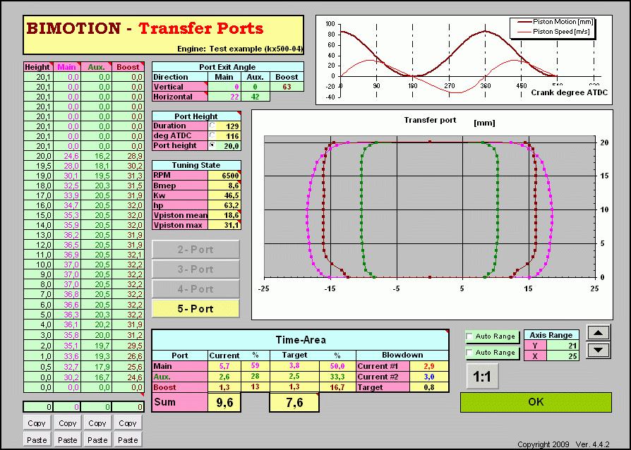
1 Bimotion Advanced Port & Pipe Case study A step by step guide about how to calculate a 2-stroke engine. 2009/aug/21. Bimotion. This paper is free for distribution and may be revised, for further references please visit KX The Kawasaki KX500 motocross cylinder will be analyzed with the software Bimotion Advanced Port&Pipe in a case study which not only shows the ordinary mapping technique but also requires some special modeling approach. This engine produces massive torque at low rpm up to peak at 6500 rpm, a time-area calculation will show this in figures too. The KX500 cylinder is a true state of the art design of 2-strokes. The brilliant KIPS exhaust system has an elevating upper valve, side sub port slide valves connected to a chamber which reduces the non-phased wave energy from the pipe at lower rpm. Low rpm High rpm The program can easily calculate both phases by disabling the sub exhaust ports with a single click, but we will first check peak power rpm. 1
 Port Aperture Mapping The")


2 Work Flow As an overview, the different steps look like this: Port Aperture Mapping Port Flow Mapping - Horizontal - Vertical Converting Developed Shape to Projected Filling in Exhaust Port Data Filling in Transfer Port Data Making Time-Area Analysis Making Port Changes Design a pipe to fit the ports (Not in this case study) Port Aperture Mapping The first step is to map the cylinder ports. A good advice is to use a special grid paper for best accuracy. (You will see why). Print your own from e.g Place the paper in the cylinder and fix it with some tape, be sure to fit it straight and tight to the wall. Use your fingers to massage the paper to the port edges, making reliefs. Remove and develop the paper and fill in the edges with a pen, be very accurate. The result will look like this: Auxiliary exhaust High rpm Low rpm Intake side Boost transfer Auxiliary transfer Main exhaust Main transfer We will now measure the port width for each mm height, using Bottom Dead Center (BDC) as the height reference. Make a scan of the paper and work in a zoom view of the picture in the pc. As you can see, it s quite easy to get correct accuracy with the mm grid paper. If the Exhaust main port is symmetric (which it should be) you only need to measure one side and double the width. Make a table for each port starting from zero at BDC and fill in the width s to the top. At locations where the curve turns to the 2


3 horizontal direction, half mm height s or less can be measured to get a nice curvature. Do the same with the transfer ports, but with the complete way around since they are smaller. The main port is here non-symmetric, but that makes no different in the calculation, the actual modeling will always be symmetric. The Exhaust sub auxiliary s needs to be treated in a somewhat different manner. For better visibility, the port is modeled non-symmetric. The port is split in to two parts, in left and right side at the highest location by a vertical center line. Left and right width contours (green and blue lines) are measured individually to the center line at the same height values. Specify this in your table. The KX500 cylinder has the very uncommon layout of two exhaust auxiliaries, so we need to cheat some to make that work. We simply add both left width values and both right width values, merging it to a single port (in two halves). As said before, the true non-symmetric shape has no influence on the calculation; it s only for a better layout visibility. The exhaust auxiliary ports will be merged to one port in the program. For the port mapping shown above we used the freeware Engauge Digitizer [1], but this can be made manually without problems. This mapping is only a picture of the port aperture in the cylinder, perpendicular to the surface. It says nothing about the flow directions or the actual flow. 3


4 BIMOTION Port Flow Mapping It is very important to understand the differences between port apertures and flow directions. The port time area is calculated from the perpendicular opened direction and reduced with the flow angle. Both horizontal and vertical angles should be measured. An example of the exhaust port directions are shown below: Horizontal Directions The easiest way to go for measuring horizontal angles is to take a picture of the ports from a central point from above like the picture below. We used the measuring tool in the freeware IrfanView [2] to measure angles in the picture. Main Transfer: The main transfer port is estimated to have a flow in 22 deg to the perpendicular direction. The blue lines show the wall directions and the mean flow should be in the middle of these (white line). Auxiliary Transfers: Flow direction: 42 deg. The walls have very diverging directions, but this is part of the stratified porting close to the aperture. Flushing water into the ports will show the flow behavior and direction too. Main Exhaust and Boost: 0 deg. (perpendicular) 4

5 Auxiliary Exhausts: Each wall from each port (red lines) are shown, the other wall is parallel so this is the flow direction. However, since we had to merge the two ports earlier, we need to find a mean value for the flow dependent on each ports capacity. Our estimation is 47 deg. Vertical Directions The vertical angles were measured by placing a small stick (red in picture) to the upper part of the port (which decides the flow direction) and measuring the stick length and the distance to the wall. (This method is possible in a big bore like this, but harder with smaller cylinders) C= arcsin(b/a) Vertical port angle is then 90-C deg. Transfer ports: 0 deg. Boost Port: 63 deg. Auxiliary Exhaust (mean value): 5 deg Main Exhaust: 35 deg. Converting Developed Shape to Projected It s now time to start Bimotion Advanced Port & Pipe! See the screenshots [3] at the end of this paper. The flow is assumed to be one-dimensional which means that the flow will only see a port in a projected view. We subsequently need to convert the developed width from the plane paper back to the curved projected shape. Click Exhaust Port #1 Tab at the bottom and fill in correct engine dimensions. If rod length is not known then assume twice the stroke. Click the Port Mapping, the following page appears: Here are 5 identical tables (Table #1 - #5) where you should convert our port width data. Note that only the Bore dimension in Engine Dim ; in tab Exhaust Port #1 ; is connected to the Port Mapping tables. Fill in your port width starting from BDC at the bottom of the table and move upwards for each measured height step. You only need to convert the width; the height isn t affected by the projection. Remaining cells at the top of the table 5


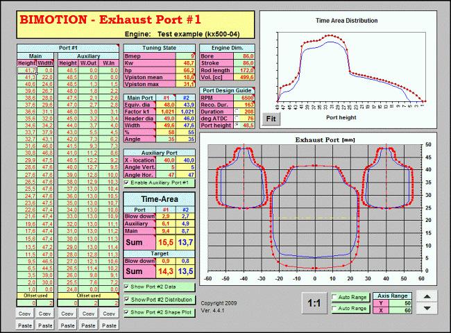
6 should be zero. (Here all but one is used since the port is very high). Repeat for all ports in the rest of the tables. Click Copy below the table, e.g. your main exhaust width data. Click Exhaust Port #1 tab and button Paste under the table Port#1; Main; Width. It s easiest to use these buttons since the cell formats are remained. If you by any reason choose to paste into any cells by any other way, be sure to use Paste Special and values only. Now fill in the height data as well. Repeat the procedure with the other ports from the Mapping page in Exhaust Port #1 and Transfer Ports. ( W.Out and W.In refers to width inner and width outer.) Copy each table (click button) from Exhaust Port #1 to Exhaust Port #2. Filling in Exhaust Port Data When you make changes in Exhaust Port #1 it will also affect the pipe calculation. Changes in Exhaust Port #2 are now your reference as the original layout and are not connected to the pipe calculations. In #2, fill in the original header dia, e.g. the inside dia of the cylinder flange. (Flange dia and header dia should match, if they don t, use the Flange dia.) In this case #2 flange dia is 46mm and the header 49mm, not so good. The relation between flange dia and port area is important, called Factor K1 It should be within a certain value dependent on tuning degree (enduro mx, RR). The small red triangles in the cells give additional information, recommended values and ranges is slightly low for this application, indicating that the port area is a little bit low. However, the flange should match the header pipe so we need to grind it to 49mm to match the header. That will also match the K1 factor better. Without port modifications and with 49mm flange, K1 would be We made some change to the port and went down to which maybe is low but will do. The angle (vertical only) was measured to 35 deg. The x-location of the auxiliary port is only for layout mapping, it does not affect any calculation. The measured angles are entered too. Max power is expected to be produced at 6500 rpm. Normally, a recommended duration at this rpm would be 163 deg, but this engine is special. The auxiliaries are placed above the main port and that opening height is used as port height. However, since the auxiliary port has a decompression upper shape for low rpm, we estimate the true height to 45 mm at peak rpm (white line). By clicking any of the option buttons either measure can be entered, mm, deg ATDC or duration. Or, if a desired duration is entered, the corresponding port height is returned. 6


7 Important to know about tima-area and port design The time-area measure is only a section flow measure of the port aperture as said earlier. This means that the actual t-a requirement for the calculated engine will vary dependent on the port layout, port channel shape and channel surface roughness. The nominal state is the untouched original design, in this case with a t-a target estimated to 13.9 s/mm. ( mm 2 s/cc =13.9 s/mm). This measure is independent of cylinder size since it is divided by the cc, thus can be compared with other engines sizes with the same type of porting if we like. However, with a careful and well performed cylinder porting, only considering the port channels, the channel flow will increase significantly. From calculation point of view, this lowers the port aperture time area requirement to produce the estimated hp s, and the change can be as much as 1s/mm. By other means, the total flow and BMEP will increase at the nominal t-a. This cylinder was ported for maximum flow (and with a small exhaust port area and timing adjustment independent of that), so we can use 1s/mm for compensation. This is done by increasing the BMEP value from nominal 8.2 to 9.7, changing the target t-a from 13.7 to 14.7 s/mm. (You do not change the port t-a, only the target value! ) The hp output will increase to about 71hp. This engine was not run in bench to confirm the figures, but an experienced test ride does confirm the change. It should also be said that a bad port configuration and shape may lower the flow with the corresponding value of 1 s/mm. This leaves the actual time-area target bounds to ± 1 s/mm from nominal value. Making the port analysis At this point we are ready to make some analysis of the power capability regarding the exhaust ports. According to the recommendations, the motocross tuning degree should be defined as approximately 9 bar bmep (braked mean efficiency pressure). We also know that a 500cc mx engine produces about 62-65hp. That is usually the power the rear tire can transmit by traction on an average motocross circuit. Now if we change the bmep value, the time-area target sum and hp will change. (Stock configuration is changed in Exhaust Port #2 ). More hp requires more t-a. If we adjust the bmep so the target t-a matches with the actual port t-a, we will get a good estimation of the actual peak power, assuming that everything else is well designed and state of the art. This simple time-area calculation says that the exhaust delivers about 60hp stock, which probably is very close to reality. The ride feeling of this engine is a massive bottom and midrange but without any distinctive upper peak, as it s holding back. This could be the evidence in figures! 7

8 In order to increase the peak power we increase bmep in Exhaust Port #1 which tells us which corresponding t-a we need. About 3 more nominal hp s at top end would be desired and will probably not affect the low rpm power significantly. We can not increase the port area too much either since the K1 factor may change out of range that would cost us a new exhaust pipe In order to increase the hp s even more we perform a skilled port shape work to increase the port channel flow capability. According to above discussion, this changes the t-a target by 1 s/mm, increasing the BMEP, thus hp to 71hp s. When we make preview changes to the ports we don t need to change the port shape in the first place. By using the offset cells in the tables (marked blue in picture) we can estimate the effect of raising or widening the ports quickly. The effect of a different cylinder gasket will be revealed instantly. If a suitable offset value is found, then we don t have to change the whole table either to make it permanent with zero offset. Table #6 in the Port Mapping will do this. Copy the table with the button and paste it into Table #6. Apply the offset and copy, paste back again. If we would like to increase the peak rpm with more hp, we must keep the current time-area (mass flow) at the increased rpm. The time area will decrease as we enter a higher rpm (less time for flow), so we need to remove material somewhere. At this point it s important to understand the t-a distribution over the port. The distribution chart (to the right) shows the relation. When we decided to choose 45 mm as the efficient port height for the auxiliary exhausts, we could see that this was a good point from total flow point of view in the distribution chart. Below 45mm (thin green line), the importance of the port flow increases dramatically. This is not easy to see by just watching the port itself. A t-a distribution example: A 1mm high, 10mm wide (10mm 2 ) area at the top of the port is opened for sek during one stroke which is equal to t-a 0.051mm 2 *s. At the bottom, at BDC, the piston opens the last mm for only sek, equal to t-a 0.014mm 2 *s. Removing 10mm 2 at the bottom of the port will nominally only increase the t-a flow capability by 27% compared to the top, but increasing the port area just as much (which affects factor K1 and the pipe). In reality, the difference is much larger since the pressure is much higher at the top of the port just as it opens. Maybe there is no pressure difference at all (no flow) as the port is fully opened and the lower part change will 8


9 make no difference at all At this point the pipe influence must be considered, understanding when the pulses arrive and to what magnitude. Above 9000 rpm there is a low pressure secondary pulse arriving from the tailpipe which increases the scavenging efficiency. A lower port modification will in that case have just as much influence to that pulse as in the top region (not applicable on this engine). More details about time-area and time-area distribution can be studied on the Bimotion webpage in the Theory section. Filling in Transfer Port Data We have 5 transfer ports which are modeled by symmetry for simplified and comparable viewing. The same procedure goes with the transfers as with the exhaust ports, making the projections and applying angles etc. The port height of 20mm gives us 129 deg duration, which is ok for a good balance between midrange and peak power. The transfer Tuning State table applies to the Exhaust Port #1 values, the same as referenced with the pipe calculations. Now down to the interesting part again; time-area. We can see the target values for the different ports and actual values. Everything is on target except the main transfer which is dimensioned for massive midrange torque Even with the increased bmep giving 63 hp it will be over target, there is nothing we need to do here! The blow down targets should be treated with care; it is not proved to be a perfect measure since it is widely dependent on pipe design. Since big bore motocross engines needs a very wide power band, the pipe angles (read exhaust pulses) will not be in line with a smaller engines, tuned for peak power only. This is why this engine needs much more blow down charging to the pipe. We could also see this in the exhaust duration. If we want to make a port change, then there is a development printout available for reverse port mapping in the Development Chart sheet. Paste inside cylinder and start grinding. 9
![References [1] Engauge Digitizer,](/docs-images/77/75745161/images/10-0.jpg "http://digitizer.sourceforge.")
![net [2] Irfan View, www.irfanview.](/docs-images/77/75745161/images/10-1.jpg "com, measuring tool accessible with short key")
10 References [1] Engauge Digitizer, [2] Irfan View, measuring tool accessible with short key F12 [3] Bimotion Advanced Port & Pipe screenshots: 10
11 11
PORSCHE V r Valve Timing Instructions. Copyright 2009 Written by Mike Frye Edited my Adam G.
 PORSCHE 928 32V r Valve Timing Instructions Copyright 2009 Written by Mike Frye Edited my Adam G. Sections: Overview.3 Disclaimer/warnings/things to watch for 4 Terms and naming conventions used in this
Dynamics of Machines. Prof. Amitabha Ghosh. Department of Mechanical Engineering. Indian Institute of Technology, Kanpur. Module No.
 Dynamics of Machines Prof. Amitabha Ghosh Department of Mechanical Engineering Indian Institute of Technology, Kanpur Module No. # 04 Lecture No. # 03 In-Line Engine Balancing In the last session, you
Throttle Cable Pull - Patent Pending By: NetGain Controls, Inc.
 Throttle Cable Pull - Patent Pending By: NetGain Controls, Inc. Powering the future! Installation Guide 2011 All Rights Reserved NetGain Controls, Inc. 1 of 8 Introduction Thank you for purchasing a NetGain
VALVE ADJUSTMENT. To perform a valve adjustment, the engine must be cold: minimum of 4 hours after shutoff, overnight is preferable.
 VALVE ADJUSTMENT The following instructions cover valve adjustment on nonhydraulic (solid lifter) engines. Check the specification sheet on your vehicle to establish your specific engine. If not available,
UNDERSTANDING ROD RATIOS
 UNDERSTANDING ROD RATIOS By Larry Carley, Technical Editor lcarley@babcox.com Performance engine builders are always looking at changes they can make that will give their engine an edge over the competition.
ProECU EVO X. Tuning Guide 2008-onward Model Year. v1.8
 ProECU EVO X Tuning Guide 2008-onward Model Year v1.8 Contents ECU Map Descriptions... 3 3D Maps... 3 Fuel Maps Shown in Live Data as Injector % and Injector ms... 3 High Octane... 3 Low Octane... 3 Ignition
Troubleshooting Guide for Okin Systems
 Troubleshooting Guide for Okin Systems More lift chair manufacturers use the Okin electronics system than any other system today, mainly because they re quiet running and usually very dependable. There
Troubleshooting Guide for Limoss Systems
 Troubleshooting Guide for Limoss Systems NOTE: Limoss is a manufacturer and importer of linear actuators (motors) hand controls, power supplies, and cables for motion furniture. They are quickly becoming
PRESEASON CHASSIS SETUP TIPS
 PRESEASON CHASSIS SETUP TIPS A Setup To-Do List to Get You Started By Bob Bolles, Circle Track Magazine When we recently set up our Project Modified for our first race, we followed a simple list of to-do
SHAFT ALIGNMENT FORWARD
 Service Application Manual SAM Chapter 630-76 Section 24 SHAFT ALIGNMENT FORWARD One of the basic problems of any installation is aligning couplings or shafts. Therefore, this section will endeavor to
GM A-Body Instructions 3 & 2½ Header Applications w/ Balance Tube Crossover
 GM A-Body Instructions 3 & 2½ Header Applications w/ Balance Tube Crossover Included with this kit are the following: 2 Collector Reducers 1 Balance Tube Kit A 2 Headpipes 2 Tailpipes 2 Tailpipe Extensions
Inside a typical car engine. Almost all cars today use a reciprocating internal combustion engine because this engine is:
 Tech Torque HOW PETROL ENGINES WORK The Basics The purpose of a gasoline car engine is to convert gasoline into motion so that your car can move. Currently the easiest way to create motion from gasoline
Precision Degree Wheel Kit
 555-81621 Precision Degree Wheel Kit Instruction Booklet Instructions for 81621 Camshaft Degree Kit Thank you for purchasing the Jegs Camshaft Degree Kit. Please follow these detailed instructions to properly
By Bob Markiewicz. Figure 1. Figure 2
 can greatly help you develop horsepower and better understand ignition timing. By understanding the mixture burns at a slow rate, compared to an explosion, and knowing that by increasing this burn rate
Replacing the hub oil seal.
 Replacing the hub oil seal. The most common reason for hub oil seal failure is a blocked axle breather, so check this first before you start. Remove the brass bell-shaped fitting on the top of the axle,
This is what we are trying to create in the steps below
 You will need: (1) Some 3/4 aluminium or steel flat bar (+/- 1 foot) (2) About 12 of 3 Aluminium or steel tubing. (2) Piece of 3X3 silicone hose and 2 hose clamps (3) 1 K&N (or similar) high flow filter
KIT TOOLS MANUAL For Engine Assembly
 KIT TOOLS MANUAL For Engine Assembly Preface This manual provides motorcycle teams with clear information on a line of tools that simplify basic tuning. We believe that these tools make engine tuning accessible
RS-2 SINGLE ACTION REAR BUMPER WITH TIRE CARRIER INSTALL MANUAL FOR JEEP WRANGLER ALL MODELS.
 RS-2 SINGLE ACTION REAR BUMPER WITH TIRE CARRIER INSTALL MANUAL FOR 2007-2016 JEEP WRANGLER ALL MODELS. Rear Bumper Installation Instructions 1) Remove factory rear bumper, (this includes all tow hitch
BeetleBot. The Simple Zippy Screw-Together Robot Kit! SKU: K JB. jb/
 BeetleBot The Simple Zippy Screw-Together Robot Kit! www.solarbotics.com 1-866-276-2687 SKU: K JB http://www.solarbotics.com/products/k_ jb/ Document Revision: January 05 2016 Shell Board 2 x Sensor Wires
Motions and Forces Propeller
 Motions and Forces Propeller Discovery Question What are the effects of friction on the motion of the propeller-driven cart? Introduction Thinking About the Question Materials Safety Trial I: Adding a
Fuel Strategy (Exponential Decay)
") By Ten80 Education Fuel Strategy (Exponential Decay) STEM Lesson for TI-Nspire Technology Objective: Collect data and analyze the data using graphs and regressions to understand conservation of energy
By Ten80 Education Fuel Strategy (Exponential Decay) STEM Lesson for TI-Nspire Technology Objective: Collect data and analyze the data using graphs and regressions to understand conservation of energy
ECT Display Driver Installation for AP2 Module
 ECT Display Driver Installation for AP2 Module Overview The ECT Display Driver is a small module with a removable wire harness that mounts behind the driver's foot well cover. All wiring connections are
INSIDE YOUR HOLLEY CARBURETOR FUEL INLET SYSTEM
 INSIDE YOUR HOLLEY CARBURETOR The carburetor is quite simply a fuel metering device that operates under the logical and straightforward laws of physics. It has evolved over the years from a very simple
CHASSIS DYNAMICS TABLE OF CONTENTS A. DRIVER / CREW CHIEF COMMUNICATION I. CREW CHIEF COMMUNICATION RESPONSIBILITIES
 CHASSIS DYNAMICS TABLE OF CONTENTS A. Driver / Crew Chief Communication... 1 B. Breaking Down the Corner... 3 C. Making the Most of the Corner Breakdown Feedback... 4 D. Common Feedback Traps... 4 E. Adjustment
S1 Sequential. T56 Magnum. Sequential shifter. Contents and assembly instructions
 S1 Sequential Sequential shifter T56 Magnum Contents and assembly instructions Parts List Sequential shifter x1 Base plate x1 Base spacer x1 Drill Square x1 Shaft fitting x1 Square washer x1 8mm Aluminium
In order to discuss powerplants in any depth, it is essential to understand the concepts of POWER and TORQUE.
 -Power and Torque - ESSENTIAL CONCEPTS: Torque is measured; Power is calculated In order to discuss powerplants in any depth, it is essential to understand the concepts of POWER and TORQUE. HOWEVER, in
Common Terms Selecting a Turbocharger Compressor... 4
 TURBOCHARGERS Common Terms... 2 Adiabatic Efficiency... 2 Pressure Ratio... 2 Density Ratio... 2 Turbine... 2 A/R Ratio... 2 Charge-Air-Cooler... 2 Boost... 3 Waste Gate... 3 Turbo Lag... 3 Boost Threshold...
Technical Math 2 Lab 3: Garage Door Spring 2018
 Name: Name: Name: Name: As you may have determined the problem is a broken spring (clearly shown on the left in the picture below) which needs to be replaced. I. Garage Door Basics: Common residential
Appendix 9: New Features in v3.5 B
 Appendix 9: New Features in v3.5 B Port Flow Analyzer has had many updates since this user manual was written for the original v3.0 for Windows. These include 3.0 A through v3.0 E, v3.5 and now v3.5 B.
BIMOTION ADVANCED HEAD MANUAL. Copyright 2017 Bimotion, Ver
 BIMOTION ADVANCED HEAD MANUAL Copyright 2017 Bimotion, Ver 2.5.0 www.bimotion.se The Bimotion Advanced Head software is copyrighted, which means that it is not allowed to be copied, loaned, cracked, changed,
Volkswagen DCC Adaptive Chassis Control - Design and Function DCC Adaptive Chassis Control. Basics of the damping system
 Volkswagen DCC Adaptive Chassis Control - Design and Function DCC Adaptive Chassis Control The rule for suspension systems has always been that increasing sportiness compromises the ride. In this new system
Eurocompulsion Camshaft Installation
 Eurocompulsion Camshaft Installation Introduction, please read. The purpose of this article is too assist our customers with installation of a performance camshaft in the Fiat Multiair 1.4 Turbo. The operation
GT-Suite Users Conference
 GT-Suite Users Conference Thomas Steidten VKA RWTH Aachen Dr. Philip Adomeit, Bernd Kircher, Stefan Wedowski FEV Motorentechnik GmbH Frankfurt a. M., October 2005 1 Content 2 Introduction Criterion for
Modular Engine 1, 2008 revision August 3, 2008
 Modular Engine 1, 2008 revision August 3, 2008 David Kerzel 2008 Back in 2002 I wanted to build a bunch of different engines without a lot of detail to learn how to build an engine, what works and what
INTRODUCTION Principle
 DC Generators INTRODUCTION A generator is a machine that converts mechanical energy into electrical energy by using the principle of magnetic induction. Principle Whenever a conductor is moved within a
X.L. BAND W/ SPRING ASSIST INSTRUCTION MANUAL
 PARTS LIST X.L. BAND W/ SPRING ASSIST INSTRUCTION MANUAL (2) Bands (1) Handle assembly (2) Side hinge assemblies (1) Left rear hinge assembly (1) Right rear hinge assembly (2) front spring s (2) rear spring
EngMod2T. The Multi-Cylinder Two-Stroke Engine Simulator. PO Box Clubview, CENTURION 0014 REPUBLIC OF SOUTH AFRICA
 PO Box 13339 Clubview, CENTURION 0014 REPUBLIC OF SOUTH AFRICA Tel: +27 12 663-4024 Fax: +27 12 663-4024 Cell: +27 82 338 1800 vannik@mweb.co.za EngMod2T The Multi-Cylinder Two-Stroke Engine Simulator
Base Plate Modeling in STAAD.Pro 2007
 Base Plate Modeling in STAAD.Pro 2007 By RAM/STAAD Solution Center 24 March 2007 Introduction: Base plates are normally designed using codebase procedures (e.g. AISC-ASD). Engineers often run into situations
BIMOTION 2-STROKE MANUAL
 BIMOTION 2-STROKE MANUAL Copyright 2001 Billy Alvarsson. Ver 3.1.6 This manual does not explain all theory behind the calculations. It is assumed that the user knows fundamentals about two stroke engines.
Pearls from Martin J. King Quarter Wave Design
 Pearls from Martin J. King Quarter Wave Design An introduction by Bjorn Johannesen, Denmark. September the 1 st 2005. The first time you visit http://www.quarter-wave.com/, you might get overwhelmed by
Heat Engines Lab 12 SAFETY
 HB 1-05-09 Heat Engines 1 Lab 12 1 i Heat Engines Lab 12 Equipment SWS, 600 ml pyrex beaker with handle for ice water, 350 ml pyrex beaker with handle for boiling water, 11x14x3 in tray, pressure sensor,
Introduction: Supplied to 360 Test Labs... Battery packs as follows:
 2007 Introduction: 360 Test Labs has been retained to measure the lifetime of four different types of battery packs when connected to a typical LCD Point-Of-Purchase display (e.g., 5.5 with cycling LED
V 2.0. Version 9 PC. Setup Guide. Revised:
 V 2.0 Version 9 PC Setup Guide Revised: 06-12-00 Digital 328 v2 and Cakewalk Version 9 PC Contents 1 Introduction 2 2 Configuring Cakewalk 4 3 328 Instrument Definition 6 4 328 Automation Setup 8 5 Automation
Actual CFM = VE Theoretical CFM
 Here is a brief discussion of turbo sizing for a 2.0 liter engine, for example, the 3-SGTE found in the 91-95 Toyota MR2 Turbo. This discussion will compare some compressor maps from the two main suppliers
Replacing MK4 Golf/Jetta radiator mounts in-car
 Replacing MK4 Golf/Jetta radiator mounts in-car This is a guide to replacing the radiator mounts in a MK4 Golf/Jetta. This involves moving the core support to the service position which allows you to do
UT Lift 1.2. Users Guide. Developed at: The University of Texas at Austin. Funded by the Texas Department of Transportation Project (0-5574)
") UT Lift 1.2 Users Guide Developed at: The University of Texas at Austin Funded by the Texas Department of Transportation Project (0-5574) Spreadsheet Developed by: Jason C. Stith, PhD Project Advisors:
UT Lift 1.2 Users Guide Developed at: The University of Texas at Austin Funded by the Texas Department of Transportation Project (0-5574) Spreadsheet Developed by: Jason C. Stith, PhD Project Advisors:
INSTALLATION INSTRUCTIONS
 HIGH FLOW AIRFLOW METER INSTALLATION INSTRUCTIONS PART NUMBER D763-1600A APPLICATION: 2001-06 E46 M3 Parts List: Hose clamp 64Z (7) Plastic Rivets Air Filter Temp Sensor & Harness (2) Button Head Screws
Draft Unofficial description of the UNRC charger menus
 Table of contents 1. The main screen... 2 2. Charge modes overview... 2 3. Selecting modes... 3 4. Editing settings... 3 5. Choose default charge mode... 4 6. Edit memory banks... 4 7. Charge mode description...
Learning to Set-Up Your Warrior Drive Belt Arizona Warrior (Rev4) BEFORE GETTING STARTED
 BEFORE GETTING STARTED") BEFORE GETTING STARTED 1. A noise one guy calls 'howling' is the same noise another guy calls 'squealing' so unless you are both hearing the noise with your own ears its better to not assume a drive belt
BEFORE GETTING STARTED 1. A noise one guy calls 'howling' is the same noise another guy calls 'squealing' so unless you are both hearing the noise with your own ears its better to not assume a drive belt
Mopar 8 3/4 & 9 3/4 (Dana) Installation Instructions Rear Disc Conversion
 Installation Instructions Rear Disc Conversion") Mopar 8 3/4 & 9 3/4 (Dana) Installation Instructions Rear Disc Conversion This kit is for either Mopar 8 ¾ or Mopar 9 ¾ (Dana). This kit is designed to work with axles with either GM 5 x 4.75 Bolt Pattern
Mopar 8 3/4 & 9 3/4 (Dana) Installation Instructions Rear Disc Conversion This kit is for either Mopar 8 ¾ or Mopar 9 ¾ (Dana). This kit is designed to work with axles with either GM 5 x 4.75 Bolt Pattern
Triumph Street Triple VSM Grip Heater Install
 Triumph Street Triple VSM Grip Heater Install Introduction: With winter fast approaching and with painful memories of last winter riding with the club it was time to do something about getting some grip
Coleman Air Diversion Controller Model C40
 Coleman Air Diversion Controller Model C40 Version 2.0 With Extended Diversion Mode Designed for 12 volt battery based systems. The Coleman Air model C40 charge controller is a compact, simple to use controller
ALIGNING A 2007 CADILLAC CTS-V
 ALIGNING A 2007 CADILLAC CTS-V I ll describe a four-wheel alignment of a 2007 Cadillac CTS-V in this document using homemade alignment tools. I described the tools in a previous document. The alignment
NEW CAR TIPS. Teaching Guidelines
 NEW CAR TIPS Teaching Guidelines Subject: Algebra Topics: Patterns and Functions Grades: 7-12 Concepts: Independent and dependent variables Slope Direct variation (optional) Knowledge and Skills: Can relate
Vacuum Readings for Tuning and Diagnosis
 Vacuum Readings for Tuning and Diagnosis -Henry P. Olsen Once you learn to properly interpret its readings, a vacuum gauge can be one of the most useful tools in your toolbox. 22 FEATURE Some people consider
Sequential Turn Signals TCSF-03 Installation Instructions FOR ONLINE INSTRUCTIONS VISIT OUR WEBSITE AT
 Sequential Turn Signals TCSF-03 Installation Instructions FOR ONLINE INSTRUCTIONS VISIT OUR WEBSITE AT WWW.FOXTHUNDERCATS.COM/ELECTRONIXX Thank you for your purchase of the TCSF-03 Sequential Turn Signal
1996+ Yamaha G16 / G22 Yamaha G29/YDRA Drive
 Vegas Carts & Performance 2995 Coleman St North Las Vegas, NV 89032 702-530-7753 VegasCarts.com 625cc Big Block Installation Instructions 1996+ Yamaha G16 / G22 Yamaha G29/YDRA Drive Revised 8/6/2018 1
KISSsoft 03/2013 Tutorial 15
 KISSsoft 03/2013 Tutorial 15 Bevel gears KISSsoft AG Rosengartenstrasse 4 8608 Bubikon Switzerland Tel: +41 55 254 20 50 Fax: +41 55 254 20 51 info@kisssoft.ag www.kisssoft.ag Contents 1 Starting KISSsoft...
Fig 1 An illustration of a spring damper unit with a bell crank.
 The Damper Workbook Over the last couple of months a number of readers and colleagues have been talking to me and asking questions about damping. In particular what has been cropping up has been the mechanics
SUZUKI RG60 RACE ENGINE SPEC SHEET
 SUZUKI RG60 RACE ENGINE SPEC SHEET The stroked RG60 build for the 1990 race season. Coker Race Products take no responsibility for any problems you may encounter when executing these specifications. The
Common Terms Types of Intake Manifolds... 5
 INDUCTION SYSTEMS Common Terms... 2 Plenum... 2 Helmholtz Resonator... 2 Intake Runners... 2 Carburetor Spacers... 2 Individual Runners (IR)... 2 Tuned Port... 3 Manifold Heat... 3 Venturi... 3 Booster
55-64 Full Size GM (Impala, Bel Air, etc.) This kit is for axles with a 3 3/8 spread center to center on the top two bolt holes (pictured left).
 This kit is for axles with a 3 3/8 spread center to center on the top two bolt holes (pictured left).") SUM-BK1624A Full Size GM Installation Instructions Rear Disc Conversion 55-64 Full Size GM (Impala, Bel Air, etc.) This kit is for axles with a 3 3/8 spread center to center on the top two bolt holes (pictured
SUM-BK1624A Full Size GM Installation Instructions Rear Disc Conversion 55-64 Full Size GM (Impala, Bel Air, etc.) This kit is for axles with a 3 3/8 spread center to center on the top two bolt holes (pictured
Dynamics of Machines. Prof. Amitabha Ghosh. Department of Mechanical Engineering. Indian Institute of Technology, Kanpur. Module No.
 Dynamics of Machines Prof. Amitabha Ghosh Department of Mechanical Engineering Indian Institute of Technology, Kanpur Module No. # 05 Lecture No. # 01 V & Radial Engine Balancing In the last session, you
Crankcase scavenging.
 Software for engine simulation and optimization www.diesel-rk.bmstu.ru The full cycle thermodynamic engine simulation software DIESEL-RK is designed for simulating and optimizing working processes of two-
Part 1. The three levels to understanding how to achieve maximize traction.
 Notes for the 2017 Prepare to Win Seminar Part 1. The three levels to understanding how to achieve maximize traction. Level 1 Understanding Weight Transfer and Tire Efficiency Principle #1 Total weight
Computer Power. Figure 1 Power-curves from Viper and Venom bottom left and right. (Source: D Quinlan)
") Introduction Computer Power The content of this article is, as you might guess, not about computer performance but rather how engine power can be predicted through the use of engine simulation tools. Little
Introduction Computer Power The content of this article is, as you might guess, not about computer performance but rather how engine power can be predicted through the use of engine simulation tools. Little
Measuring Threaded Holes
 Measuring Threaded Holes It s a common question In PC-DMIS I can use the pitch function within a circle feature so the probe would "follow" the thread. How are tapped holes measured in Calypso? I have
GruvenParts.com BRASS GM Power Folding Mirror Gear Replacement Instructions. Updated 8/25/2017 Additional Pictures / Tips Posted!
 Page 1 GruvenParts.com BRASS GM Power Folding Mirror Gear Replacement Instructions Updated 8/25/2017 Additional Pictures / Tips Posted! ** Latest Design is uses an ALL BRASS SPUR GEAR!!! ** ** If you don
2 Dynamics Track User s Guide: 06/10/2014
 2 Dynamics Track User s Guide: 06/10/2014 The cart and track. A cart with frictionless wheels rolls along a 2- m-long track. The cart can be thrown by clicking and dragging on the cart and releasing mid-throw.
Variable Intake Manifold Development trend and technology
 Variable Intake Manifold Development trend and technology Author Taehwan Kim Managed Programs LLC (tkim@managed-programs.com) Abstract The automotive air intake manifold has been playing a critical role
ALLISON 1000 SIGNATURE SERIES
 ALLISON 1000 SIGNATURE SERIES 2001-2010 DURAMAX GPZ 1 FLUID CAPACITY INSTALLATION In our RevMax performance transmission we require you to use DEXRON 3 fluid and are shipped empty due to the regulations
The Holly Buddy. 2.5cc Model Diesel - Compression Ignition engine.
 The Holly Buddy 2.5cc Model Diesel - Compression Ignition engine. Firstly I want to dedicate this engine to David Owen. I didn t know David for very long, but his influence on me and my affection for these
ELECTRIC CURRENT. Name(s)
") Name(s) ELECTRIC CURRT The primary purpose of this activity is to decide upon a model for electric current. As is the case for all scientific models, your electricity model should be able to explain observed
Name(s) ELECTRIC CURRT The primary purpose of this activity is to decide upon a model for electric current. As is the case for all scientific models, your electricity model should be able to explain observed
GM 4L80-E, 4L85-E SURE CURE KIT
 GM 4L80-E, 4L85-E SURE CURE KIT PART NUMBER SC-4L80E INSTALLATION GUIDE Parts are labeled here in order of installation. See page 2 for details on Sure Cure kit contents. See Sure Cure instruction booklet
See a picture of each kit on the following page.
 Stainless Steel Chevelle/El Camino Dual Exhaust Kit 793-91325 (2.5 ) or 793-91330 (3.0 ) Fits 1968 1972 Chevelle/El Camino Chevy Small Block/Std Port Heads and Dynatech MuscleMaXX Headers (740-33210, 740-43210
The information below was obtained from measurements made on five cylinder heads in December 2001.
 Bristol Austin 7 Club - technical article www.ba7c.org The majority of these tips have appeared in club newsletters over the years. Please note that you use them at your own risk as neither the Bristol
Chevy Nova Pro-Touring Front Suspension Installation Instructions
 1962-1967 Chevy Nova Pro-Touring Front Suspension Installation Instructions 1-800-984-6259 www.totalcostinvolved.com 1 Pro-Touring Clip A-Arm Assembly Sway Bar Assembly Fender Panel Kit 8 7/16-20 * 1 ¼
Chevrolet 3100 IFS Kit
 1947-54 Chevrolet 3100 IFS Kit Congratulations on your purchase on what we believe is the finest IFS kit available for 1947-54 Chevrolet pickups with stock frames. We have invested many hours into designing
SpiritPFC Torque/Horsepower Comparison Dynamometer Test Date: 5/7/2006
 SpiritPFC / Comparison Dynamometer Test Date: 5/7/2006 Dynamometer Test Outline: Contained within this document you will find data collected using a Dyno Datamite engine dynamometer hardware and software
Engine Cycles. T Alrayyes
 Engine Cycles T Alrayyes Introduction The cycle experienced in the cylinder of an internal combustion engine is very complex. The cycle in SI and diesel engine were discussed in detail in the previous
HW Prowler Carburetor Installation Instructions
 HW Prowler Carburetor Installation Instructions Page 1 of 6 Carb Kit Contains: HW modified Mikuni 36mm pumper style carb Custom choke cable Fuel Line Clamp Instructions (2) Leaner and (2) richer main jets
PRESSURE SENSOR INSTRUCTIONS
 PRESSURE SENSOR INSTRUCTIONS Overview: Pressure sensors are an analog style sensor that produces a voltage from 0V to 5V depending on the amount of pressure applied and the range of the sensor. If you
GPS Speedometer Module Part # 9513A - Kawasaki Ultra 300 and 310 Models
 Part # 9513A - Kawasaki Ultra 300 and 310 Models Installation & Calibration Instructions for Kawasaki 300/310 Jet Skis Thank you for purchasing the Candoopro GPS Speedometer Module! The GPS Speedometer
4. Remove (4) 10mm and (1) 7mm bolt that holds fascia at front corners, on each side
 10mm and (1) 7mm bolt that holds fascia at front corners, on each side") 2010 Camaro LS3 1. Disconnect battery ground 2. Remove front wheels 3. Remove (5) push pins and (5) #20 torx screws on inner front wheel well liners and remove liners on each side 4. Remove (4) 10mm and
2010 Camaro LS3 1. Disconnect battery ground 2. Remove front wheels 3. Remove (5) push pins and (5) #20 torx screws on inner front wheel well liners and remove liners on each side 4. Remove (4) 10mm and
Cam Motion Case Studies #1 and # 2
 Cam Motion Case Studies #1 and # 2 Problem/Opprtunity: At an operating speed of 150 to 160 rpm, Cam Motion #1 causes the cam follower to leave the cam surface unless excessive air pressure is applied to
mygrid Installation Notes
 mygrid Introduction mygrid kits provide an easy to install, compliant, Solar Hybrid (On-Grid) or Off-Grid battery system. These installation notes outline all the processes required to effectively install
PRSalpha Air Drill (Double Valve)
") 888-680-4466 ShopBotTools.com PRSalpha Air Drill (Double Valve) Copyright 2016 ShopBot Tools, Inc. page 1 Copyright 2016 ShopBot Tools, Inc. page 2 Table of Contents Overview...5 Spindle Mounting Plate...6
888-680-4466 ShopBotTools.com PRSalpha Air Drill (Double Valve) Copyright 2016 ShopBot Tools, Inc. page 1 Copyright 2016 ShopBot Tools, Inc. page 2 Table of Contents Overview...5 Spindle Mounting Plate...6
Trouble Shooting Guide for Hubbell Systems
 Trouble Shooting Guide for Hubbell Systems NOTE: Hubbell Special Products discontinued operations in 2008, so there is a very limited number of repair parts available for motor repair. In some ways, this
CPi. CoiL PACK IGNiTioN FOR AViATiON. For 4,6 and 8 cylinder 4 stroke applications. Please read the entire manual before beginning installation.
 1 CPi CoiL PACK IGNiTioN FOR AViATiON Coil pack (4 cylinder) Coil pack (6 cylinder) For 4,6 and 8 cylinder 4 stroke applications. Please read the entire manual before beginning installation. Software version
Troubleshooting of the LubeTech Grease System
 Troubleshooting of the LubeTech Grease System February 2009 The LubeTech grease system is designed to be a preventative maintenance system that will extend the life of your bearings that are connected
HYDRA 120 & HYDRA 240 OPERATION MANUAL
 HYDRA 120 & HYDRA 240 OPERATION MANUAL The battery connector must be added to the power side of the controller (black capacitors, receiver connector, and red and black wire side). The red wire is the positive
Roehrig Engineering, Inc.
 Roehrig Engineering, Inc. Home Contact Us Roehrig News New Products Products Software Downloads Technical Info Forums What Is a Shock Dynamometer? by Paul Haney, Sept. 9, 2004 Racers are beginning to realize
60-65 Falcon, Comet & Ranchero Coil Spring IFS
 60-65 Falcon, 62-65 Comet & 62-65 Ranchero Coil Spring IFS All engine installations with this front end will require a rear sump oil pan. 289-302 Small Block Ford Motors Milodon rear sump pan holds 7 quarts
Technical Brief Prodrive Performance Packs Subaru WRX PPP Stage 2
 Technical Brief Prodrive Performance Packs Subaru WRX PPP Stage 2 Date: September 21, 2003 System: Prodrive Performance Pack Stage 2 Subaru WRX Tests: Independent Third Party Dynamometer Tests Prodrive
Using Advanced Limit Line Features
 Application Note Using Advanced Limit Line Features MS2717B, MS2718B, MS2719B, MS2723B, MS2724B, MS2034A, MS2036A, and MT8222A Economy Microwave Spectrum Analyzer, Spectrum Master, and BTS Master The limit
A /F/X Body Instruction Packet Rear Disc Conversion
 A /F/X Body Instruction Packet Rear Disc Conversion 64-72 A Body / 67-81 F Body / 62-74 X Body This kit is for axles with a 3 1/8 spread center to center on the top two bolt holes (pictured left). Rotor
4.2 Friction. Some causes of friction
 4.2 Friction Friction is a force that resists motion. Friction is found everywhere in our world. You feel the effects of when you swim, ride in a car, walk, and even when you sit in a chair. Friction can
FULL FLOATER HUB KIT INSTRUCTION MANUAL
 FULL FLOATER HUB KIT INSTRUCTION MANUAL WARNING: All components are shipped assembled for illustration purposes only. IT IS YOUR RESPONSIBILITY FOR FINAL ASSEMBLY. Please read instructions thoroughly before
Quick Guide. Unipro Laptimer Version Go faster faster. UNIPRO ApS
 Quick Guide Unipro Laptimer 5004 Version 1.32 Go faster faster UNIPRO ApS VIBORG HOVEDVEJ 24 DK-7100 VEJLE DENMARK Tel.: +45 75 85 11 82 Fax: +45 75 85 17 82 www.uniprolaptimer.com mail@uniprolaptimer.com
J&M Mustang Rear Lower Control Arms (2005+) - Installation Instructions
 - Installation Instructions") J&M Mustang Rear Lower Control Arms (2005+) - Installation Instructions The below installation instructions work for the following products: J&M Mustang Rear Lower Control Arms (2005+) Please read through
J&M Mustang Rear Lower Control Arms (2005+) - Installation Instructions The below installation instructions work for the following products: J&M Mustang Rear Lower Control Arms (2005+) Please read through