Volkswagen DCC Adaptive Chassis Control - Design and Function DCC Adaptive Chassis Control. Basics of the damping system
|
|
|
- Shon Young
- 5 years ago
- Views:
Transcription


1 Volkswagen DCC Adaptive Chassis Control - Design and Function DCC Adaptive Chassis Control The rule for suspension systems has always been that increasing sportiness compromises the ride. In this new system the DCC adaptive chassis control, the suspension constantly adjusts itself to the road conditions, the driving situation and the drivers requirements. Adjustable shock absorbers are required to make this possible. The steering assistance is also adjusted in addition to the damping. Basics of the damping system The shock absorbers have the task of quickly reducing the vibration energy of the body and road wheel oscillations. Suspension configuration The compression cycle and extension cycle are features of the suspension. The damping force in the compression cycle is normally lower than in the extension cycle. The shock absorbers prevent the body rocking due to bumps in the road and stop the wheels bouncing out of control on the road surface. Furthermore the body is also stabilised by the damping forces during dynamic manoeuvres. An even greater damping effectiveness is achieved with adjustable shock absorbers since the current driving situation can be taken into consideration more efficiently. The electronically controlled damping control unit determines within milliseconds what level of damping is required at which wheel and adjusts the shock absorber accordingly. The damping level is the rate at which the vibrations are reduced. This is dependent on the damping force of the shock absorber and the size of the sprung masses. Reducing the sprung masses increases the damping level.

2 Adjustable shock absorber An adjustable shock absorber using a twin-tube design is employed for the DCC adaptive chassis control. The piston runs in chamber 1 and there is an additional gas chamber in chamber 2.
 during extension and compression.")
3 Function in extension and compression cycle Check valves on the piston and base plate cause the oil to flow in the directions shown in the diagram during extension and compression. The oil is fed to the adjustment valve through the ring channel and it flows in the same direction (uniflow) during extension and compression. The oil flows back into chamber 2 from the adjustment valve. The adjustment valve determines the pressure in chamber 2 and thus the damping. The cylinder contains chamber 2. It is only partly filled with oil. There is a gas cushion with a de-foaming spiral above the oil filling. Chamber 2 is used to compensate changes in the oil volume. The oil flow is controlled by the damping valve units on the piston, on the chamber base and in the adjustment valve. They consist of a system of flat springs, coil springs and valve bodies with oil flow ports. During the extension cycle, the oil flow is controlled by: the adjustment valve, the base valve and to a limited extent the piston valve. During the compression cycle, the oil flow is throttled by: the adjustment valve,
4 the piston valve and to a limited extent the base valve. Map for Adjustable shock absorber Compared with a conventional shock absorber with fixed map, the adjustable shock absorber has an adjustable characteristic curve within a map.


5 Conventional shock absorbers have a characteristic curve that helps define the driving properties of the vehicle. Defining this characteristic curve is the result of the suspension configuration that is carried out for each vehicle. This depends, among other things on the weight distribution of the vehicle, the engine, the vehicle characteristics and the axle kinematics. The damping characteristic curves of the adjustable shock absorber can be modified by varying the current supplied to the adjustment valve. This creates a map. This adjustment is made in all driving modes ( Normal, Sport and Comfort ).

6 Depending on the current driving situation, the shock absorber rates are adjusted within the specified map even when a driving mode is selected. In Fail Safe mode, the adjustment valves are not powered and the shock absorbers are thus operated with a defined characteristic curve. System description DCC adaptive chassis control system The adjustable shock absorbers are regulated by a control unit that adjusts the damping according to a control algorithm developed by Volkswagen. Depending on the input signals, the whole map of the adjustable shock absorbers is used. This control algorithm can also be switched from Normal mode to Sport or Comfort mode using the button and thus adjusted to customer requirements. The system can be adjusted when the vehicle is stationary or travelling. The DCC adaptive chassis control is always active. It is an intelligent automatically controlled system that adjusts the vehicle shock absorbers depending on the road surface, the respective driving situation (e.g. braking, accelerating and cornering) and the driver s requirement. Thus the driver always has the ideal suspension setting. Notes: The driving mode last activated is also still active after the ignition is switched OFF/ON. The driving mode can be switched over while the vehicle is stationary or on the road. The adjustment valves are not powered when the vehicle is stationary. Selectable DCC modes The DCC mode can be set by the driver depending on individual requirements using the button to the right of the gear lever. Press the button until you obtain the required setting. You can repeat this as often as required. The modes are always switched through in the order Normal Sport Comfort. Normal mode
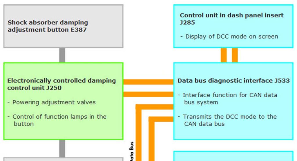
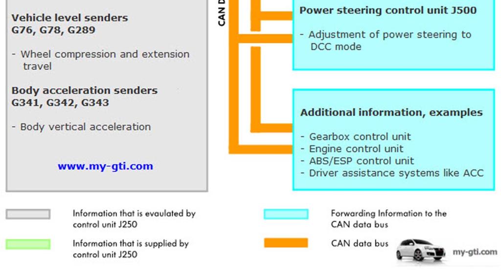
7 Normal mode is active when neither the Comfort nor Sport labels on the button are illuminated yellow. This setting provides an overall balanced, but still dynamic driving feel. It is well suited for everyday use. Sport mode This mode is active when the Sport label is illuminated yellow in the button. This setting gives the vehicle sporty handling with a harder basic configuration. The steering is also set sporty and the chassis damping is stiffer. This setting allows a particularly sporty driving style. Comfort mode This mode is active when the Comfort label is illuminated yellow in the button. This setting leads to a comfort-oriented, softer basic configuration of the chassis damping. It is suitable, for example, for driving on bad roads and for long journeys. The differences in the modes are noticeable from the varying hardness of the basic damping settings. They are superimposed by higher damping force requirements due to the driving situations. System Description Overview of components used in vehicle The diagram is a simplified depiction of the components in the DCC adaptive chassis control system and their relationships (the senders each have a separate connection to the electronically controlled damping control unit J250 they are combined for each axle in the diagram for reasons of simplicity).

8 E387 Shock absorber damping adjustment button G76 Rear left vehicle level sender G78 Front left vehicle level sender G289 Front right vehicle level sender G341 Front left body acceleration sender G342 Front right body acceleration sender G343 Rear body acceleration sender J104 ABS control unit J250 Electronically controlled damping control unit J285 Control unit in dash panel insert J500 Power steering control unit J533 Data bus diagnostic interface
9 N336 Front left shock absorber damping adjustment valve N337 Front right shock absorber damping adjustment valve N338 Rear left shock absorber damping adjustmentvalve N339 Rear right shock absorber damping adjustment valve System link to brakes and steering In the DCC adaptive chassis control, information is exchanged between the electronically controlled damping control unit and the associated networked control units via the CAN data bus. The system overview shows an example of the information that is provided via the CAN data bus or is received and used by the networked control units.
10 System description System overview
11 Function Shock absorber for DCC adaptive chassis control Twin-tube shock absorbers are used for the DCC adaptive chassis control. An electrically controlled adjustment valve mounted on the outside of the shock absorber regulates the damping force. By varying the current, the damping force of the active shock absorber setting can be adjusted within a few milliseconds by the adjustment valve. The 3 vehicle level senders provide signals that are required to calculate the necessary shock absorber setting together with the signals from the 3 body acceleration senders. The maps for the respective shock absorber setting are stored in the electronically controlled damping control unit J250. In the diagram, the ammeter is shown simply to help explain the current supplied to the adjustment valve (ammeter in Normal mode). A fixed current is not used to control the system within the Normal, Sport and Comfort modes, instead a range of values are used (see yellow-coloured area in ammeter). The following diagrams for the possible adjustment valve modes simply show the centre position of the ammeter needle within the yellow-coloured area.

12 Adjustment valve The adjustment valve is mounted on the side of the shock absorber so that oil from the shock absorber ring channel flows to the valve. The oil supplied from the adjustment valve is sent to chamber 2 of the shock absorber.

13 The valve is adjusted by applying a current to the coil (0.24 A to max. 2.0 A) and the resulting changes inside the adjustment valve. Depending on the control position of the adjustment valve, the oil flowing from the shock absorber moves the main slider to a corresponding horizontal position so that a specific amount of oil can flow back to the shock absorber through the return channel. The main slider position is achieved by setting a differential pressure (compared with the pressure of the oil flowing from the shock absorber) in the inner control volume. The differential pressure is set by pre-tensioning the gap cross-section between the pressure head and control plate. If the pre-tension becomes greater, for example, the amount of oil flowing away centrally through the main slider and further through the ring gap and control channel is reduced, the pressure increases in the inner control volume and the main piston can only be moved slightly to the right. This changes the damping behaviour towards hard. If the pre-tension becomes smaller, the system behaves in the opposite way. The damping behaviour is changed towards soft Function Adjustment valve in Normal mode
14 In Normal mode, a current in a middle range between 0.24 A and 2.0 A is supplied to the coil. The armature is moved together with the push rod and pressure head and is pre-tensioned slightly. The oil flowing from the shock absorber presses the main piston to a horizontal centre position so that a medium quantity of oil can leave again via the return channel and be fed back to the shock absorber. This is achieved by setting a medium pre-tension between the pressure head and control plate. The differential pressure is also set accordingly in the internal control volume and the position of the main piston is set in a horizontal middle position. The damping behaviour is thus between soft and hard. Adjustment valve in hard In hard, the coil is powered in a range up to a max. of 2.0 A. The armature is pressed to the left together with the push rod and pressure head with maximum pre-tensioning to the left. As a result, there are smaller gap cross-sections between the control plate and pressure head compared with Normal mode. The differential pressure in the internal control volume increases and the main piston sets itself in its horizontal position so that a lower oil quantity flows back via the return channel to the shock absorber than in Normal mode. This changes the damping behaviour towards hard. This is a typical state of the adjustment valve for a considerably dynamic maneuver.
15 Adjustment valve in soft In soft, the magnet is powered with 0.24 A, for example, and has less pre-tensioning together with the push rod and pressure head. The pressure head moves the control piston to the left by the same amount and releases the ring gap only in a slightly reduced cross-section. The oil flows via this gap and the subsequent control channel back to the shock absorber. The gap cross-section between the control plate and pressure head increases with this slightly lower pre-tensioning of the pressure head. The differential pressure in the internal control volume drops. The main piston thus sets itself in its horizontal position so that a greater amount of oil flows back via the return channel than in hard. This changes the damping behaviour towards soft. This is a typical state of the adjustment valve for a considerably dynamic manoeuvre. Adjustment valve in Fail Safe


16 If a shock absorber, at least two sensors or the electronically controlled damping control unit J250 fail, Fail Safe mode is set. In Fail Safe mode, the shock absorbers are not powered and the vehicle behaves as if fitted with conventional shock absorbers. The armature moves together with the push rod and pressure head to the right until it rests against the valve housing. The control piston also moves and closes the direct access to the ring gap. The oil now opens the fail-safe valve and flows via the control channel to the shock absorber. Electrics Electronically controlled damping unit J250 The control unit J250 is in the boot on the right-hand side behind the panelling (Passat CC). It evaluates the signals from the vehicle level senders G76, G78, G289 and the body acceleration sender G341, G342, G343 and constantly calculates the respective optimum
.")
17 current for the four shock absorbers taking the road, driving situation and driver requirement into consideration. It adjusts the shock absorbers within milliseconds using a controlled current (approx A 2.0 A). Indications in dash panel insert The suspension setting that the driver selects manually using the shock absorber damping adjustment button E387 is displayed in the dash panel insert. The setting/display last selected is available when the vehicle is started. Volkswagen level senders G76, G78, G289 The vehicle level senders are so-called turn angle sensors. They are all fitted near to the shock absorbers and are connected to the traverse links via coupling rods. The wheel spring travel is forwarded to the sensors from the movement of the traverse links on the front and rear axle and on the coupling rods and converted into an angle of rotation. The turn angle sensor used works with static magnetic fields and uses the Hall principle. The signal output supplies a PWM signal (pulse-width modulated signal) proportional to the angle for shock absorber control. The three level sensors are identical; only the mountings, the coupling rods and kinematics to the sides and axles.

18 Electrics Design

19 The sender is set up in a two-chamber system. On one side (1st chamber), there is the rotor and, on the opposite side, (2nd chamber) the circuit board with stator. The rotor and stator are each fitted so they are sealed. The rotor consists of a non-magnetised stainless steel shaft in which a rare-earth magnet is glued. Rare-earth magnets are used where high magnetic field strengths in conjunction with the smallest possible dimensions are needed. The rotor is connected to the coupling rod by the operating lever and is also driven by it. The rotor is mounted in a radial shaft seal in the operating lever. This protects the construction from the elements. The stator consists of a Hall sensor that is located on a circuit board. The circuit board is moulded in a PU mass (PU = polyurethane) and is thus also protected against external influences. Function The magnetic flow is transferred and amplified using the Hall plates. Unlike conventional Hall senders, these elements deliver special sine and cosine signals. In the chip on the circuit board, the signals are converted so that the level changes of the body are recognisable for the electronically controlled damping control unit J250.


20 Electrics Body acceleration senders G341, G342, G343 The body acceleration senders measure the vertical acceleration of the body.


21 The front left body acceleration sender G341 and front right body acceleration sender G342 are mounted on the body at the top next to the shock absorbers. The rear body acceleration sender G343 is mounted at the top next to the left-hand rear shock absorber. Design and function The body acceleration senders work according to the capacitive measuring principle. An elastic mass m oscillates between capacitor plates as a middle electrode that pulls the capacities of capacitors C1 and C2 opposite the rhythm of their oscillation. The plate spacing d1 of one capacitor is increased by the amount that spacing d2 in the other capacitor is reduced. This changes the capacities of the individual capacitors. An electronic evaluation system delivers an analogue signal voltage to the electronically controlled damper control unit J250.
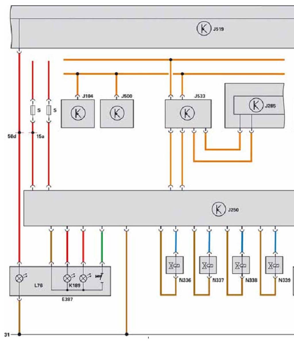
22 Sender measuring range The measuring range of the sender is + or 1.6g. g = measurement for the acceleration 1g = 9.81 m/sec2 Electrics Functional diagram
23
24 E387 Shock absorber damping adjustment button G76 Rear left vehicle level sender G78 Front left vehicle level sender G289 Front right vehicle level sender G341 Front left body acceleration sender G342 Front right body acceleration sender G343 Rear body acceleration sender J104 ABS control unit J250 Electronically controlled damping control unit J285 Control unit in dash panel insert J500 Power steering control unit J519 Onboard supply control unit J533 Data bus diagnostic interface K189 Shock absorber damping adjustment warning lamp L76 Button illumination bulb N336 Front left shock absorber damping adjustment valve N337 Front right shock absorber damping adjustment valve N338 Rear left shock absorber damping adjustment valve N339 Rear right shock absorber damping adjustment valve
Electromechanical Steering with Parallel-axis Drive
 Service Training Self-study Programme 399 Electromechanical Steering with Parallel-axis Drive Design and Function The electromechanical power steering has many advantages compared with a hydraulic steering
The electro-mechanical power steering with dual pinion
 Service Training Self-study programme 317 The electro-mechanical power steering with dual pinion Design and function The electro-mechanical power steering has many advantages over the hydraulic steering
Common rail injection system
 Common rail injection system Pressure limiting valve The pressure limiting valve is located directly on the high-pressure fuel rail. Its function is to limit maximum pressure in the high-pressure fuel
Service. adaptive air suspension in the Audi A8. Home study program 292. For internal company use only
 292 Service adaptive air suspension in the Audi A8 Home study program 292 For internal company use only The development of the running gear is subject to conflicting objectives. For now, besides "classic"
Variable Anti-roll Bars on the Touareg
 Service Training Self-Study Programme 331 Variable Anti-roll Bars on the Touareg Design and Function The running gear is a key component of the entire vehicle. It transmits all the forces acting between
The electromechanical parking brake
 Service Training Self-study programme 346 The electromechanical parking brake Design and function To make absolutely sure that the vehicle could not roll away when parked up, the driver had to pull up
Performance concept: Chassis
 Chassis Performance concept: Chassis Total vehicle concept Chassis mechanics Mechatronic chassis systems Systematic attention to driving dynamic requirements in total vehicle concept Driver-oriented operating
Vehicle Dynamic Suspension - Vehicle Dynamic Suspension Description and Operation COMPONENT LOCATION Published: 18-Dec-2013
 Vehicle Dynamic Suspension Vehicle Dynamic Suspension Description and Operation Published: 18Dec2013 COMPONENT LOCATION Item 1 2 3 4 5 6 7 8 9 10 11 12 Part Number Description RH (right hand) front spring
6-speed Automatic Gearbox 09G/09K/09M
 Service Training Self-study Programme 309 6-speed Automatic Gearbox 09G/09K/09M The 6-speed automatic gearbox from the Japanese manufacturer AISIN is used in the following Volkswagen vehicles: Code Maximum
PVL Racing Ignition Installation Instructions
 PVL Racing Ignition Installation Instructions Fit the ignition coil together with the core sheet package to the chassis frame; additionally, silent blocks may be used to absorb vehicle vibrations and shocks.
SUBJECT: Electronic Damping Control (EDC III)
") Group 37 37 01 90 (2107) Woodcliff Lake, NJ October 1990 Integrated Suspension Systems Service Engineering --------------------------------------------------------------------------------------------------------
Group 37 37 01 90 (2107) Woodcliff Lake, NJ October 1990 Integrated Suspension Systems Service Engineering --------------------------------------------------------------------------------------------------------
Vibration damper control
 Vibration damper control The damper control system registers the condition of the road surface and the movements of the vehicle via four wheel acceleration sensors and three body acceleration sensors.
iracing.com Williams-Toyota FW31 Quick Car Setup Guide
 iracing.com Williams-Toyota FW31 Quick Car Setup Guide In this guide we will briefly explain a number of key setup parameters which are distinct to the FW31 and which are new to iracing vehicles. We hope
Railway Technical Web Pages
 Railway Technical Web Pages Archive Page Vehicle Suspension Systems Introduction Almost all railway vehicles use bogies (trucks in US parlance) to carry and guide the body along the track. Bogie suspension
6-speed automatic transmission E60, E53. VS-22 je Baugruppe/Group: (040) 09/2003. Introduction
 09/2003. Introduction") VS-22 je Baugruppe/Group: 24 24 01 03 (040) 6-speed automatic transmission E60, E53 weltweit Datum/Date: 09/2003 Introduction The 6-speed automatic transmissions GA6HP19Z and GA6HP26Z have been jointly
VS-22 je Baugruppe/Group: 24 24 01 03 (040) 6-speed automatic transmission E60, E53 weltweit Datum/Date: 09/2003 Introduction The 6-speed automatic transmissions GA6HP19Z and GA6HP26Z have been jointly
Chassis Technology Workshop Cayenne
 Chassis Technology Workshop Cayenne Driving dynamic properties of all Porsche models Optimum driving dynamics and steering precision from high-performance chassis, steering and all-wheel drive systems
The 1.4 ltr. and 1.6 ltr. FSI engine with timing chain
 Service. Self study programme 296 The 1.4 ltr. and 1.6 ltr. FSI engine with timing chain Design and function For Volkswagen, new and further development of engines with direct petrol injection is an important
NEW INNOVATION. Shock Absorber Tester. Model: MAHA-Shock-Diagnostic MSD 3000
 Wir im Allgäu. Shock Absorber Tester Model: MAHA-Shock-Diagnostic MSD 3000 NEW INNOVATION For easy and accurate testing of the shock absorbers - Indirect shock absorber test based on the new Theta principle.
TORQUE-MOTORS. as Actuators in Intake and Exhaust System. SONCEBOZ Rue Rosselet-Challandes 5 CH-2605 Sonceboz.
 TORQUE-MOTORS as Actuators in Intake and Exhaust System SONCEBOZ Rue Rosselet-Challandes 5 CH-2605 Sonceboz Tel.: +41 / 32-488 11 11 Fax: +41 / 32-488 11 00 info@sonceboz.com www.sonceboz.com as Actuators
The Touareg Electrical System
 Service. Self-Study Programme 298 The Touareg Electrical System Design and Function Vehicles with off-road capability are no longer just utility vehicles for a limited group of people. At all levels in
The 1.6ltr. TDI Engine with Common Rail Injection System Design and Function
 Service Training Self-study Programme 442 The 1.6ltr. TDI Engine with Common Rail Injection System Design and Function The 1.6l TDI engine with common rail injection system will form the basis for all
Chassis development at Porsche
 Chassis development at Porsche Determining factors Challenges automotive industry Challenges chassis development e-mobility product differentiation customization driving resistance vehicle mass resource
5-speed Automatic Gearbox 09A/09B
 Service. Self-Study Programme 232 5-speed Automatic Gearbox 09A/09B Design and Function The new 5-speed automatic gearbox The new automatic gearbox is intended for installation in the Volkswagen and Audi
Shock Absorbers What is Ride Control Vehicle Dynamics Suspension System Shock Absorbers Struts Terminology
 Home Tech Support Shock Absorbers Shock Absorbers What is Ride Control Vehicle Dynamics Suspension System Shock Absorbers Struts Terminology A BRIEF HISTORY These first shock absorbers were simply two
LUCAS ACE - System Overview
 LUCAS ACE - System Overview The Active Corner Enhancement system manufactured by Rover Group Lucas appears to have been produced specifically for the Land Rover Discovery series II to address the poor
Rear Drive Axle and Differential
 Page 1 of 13 Rear Drive Axle and Differential GENERAL Item Part Number Description A - Electronic rear differential B - Open rear differential 1 - Rear driveshaft 2 - Electronic rear differential 3 - RH
1.4l TSI Engine with Dual-charging
 Service Training Self-study Programme 359 1.4l TSI Engine with Dual-charging Design and Function 1 The 1.4l TSI* engine is the world s first petrol engine with direct petrol injection and dual-charging.
ANTI-SKID BRAKING SYSTEM (ABS)
") 35B-1 GROUP 35B ANTI-SKID BRAKING SYSTEM (ABS) CONTENTS GENERAL INFORMATION........ 35B-2 SERVICE SPECIFICATIONS....... 35B-3 SPECIAL TOOLS................ 35B-4............ 35B-5 STANDARD FLOW OF DIAGNOSTIC................
35B-1 GROUP 35B ANTI-SKID BRAKING SYSTEM (ABS) CONTENTS GENERAL INFORMATION........ 35B-2 SERVICE SPECIFICATIONS....... 35B-3 SPECIAL TOOLS................ 35B-4............ 35B-5 STANDARD FLOW OF DIAGNOSTIC................
1,9 ltr-tdi-industrial Engine
 1,9 ltr-tdi-industrial Engine Technical Status: 4/1999 Contents Combustion process................3 Injectors.........................4 Needle Lift Sender.................5 Air-mass Flow Meter...............6
CHASSIS DYNAMICS TABLE OF CONTENTS A. DRIVER / CREW CHIEF COMMUNICATION I. CREW CHIEF COMMUNICATION RESPONSIBILITIES
 CHASSIS DYNAMICS TABLE OF CONTENTS A. Driver / Crew Chief Communication... 1 B. Breaking Down the Corner... 3 C. Making the Most of the Corner Breakdown Feedback... 4 D. Common Feedback Traps... 4 E. Adjustment
2018 KX65 KX - THE BIKE THAT BUILDS CHAMPIONS
 2018 KX65 KX - THE BIKE THAT BUILDS CHAMPIONS For more than 30 years, Kawasaki s smallest KX motocross bike has played a key role in the sport of motocross, providing a race-winning platform on which countless
Engine Exhaust system. Engine
 Engine Engine 272 - Exhaust system The engine of the 6-cylinder version satisfies the US exhaust emissions limits. To meet these limits the monolith coating of the catalytic converters has been modified
A double-wishbone type suspension is used in the front. A multi-link type suspension is used in the rear. Tread* mm (in.) 1560 (61.
 1560 (61.") CHASSIS SUSPENSION AND AXLE CH-69 SUSPENSION AND AXLE SUSPENSION 1. General A double-wishbone type suspension is used in the front. A multi-link type suspension is used in the rear. 08D0CH111Z Specifications
CHASSIS SUSPENSION AND AXLE CH-69 SUSPENSION AND AXLE SUSPENSION 1. General A double-wishbone type suspension is used in the front. A multi-link type suspension is used in the rear. 08D0CH111Z Specifications
Development of High Power Column-Type Electric Power Steering System
 TECHNICAL REPORT Development of High Power Column-Type Electric Power Steering System Y. NAGAHASHI A. KAWAKUBO T. TSUJIMOTO K. KAGEI J. HASEGAWA S. KAKUTANI Recently, demands have increased for column-type
Variable Valve Timing
 Service. Self-study programme 246 Variable Valve Timing with fluted variator Design and Function The demands on combustion engines continue to grow. On one hand, customers want more power and torque, while
CHAPTER THREE DC MOTOR OVERVIEW AND MATHEMATICAL MODEL
 CHAPTER THREE DC MOTOR OVERVIEW AND MATHEMATICAL MODEL 3.1 Introduction Almost every mechanical movement that we see around us is accomplished by an electric motor. Electric machines are a means of converting
Magneto-Rheological (MR) Suspension Systems FOR INDUSTRIAL APPLICATIONS
 Suspension Systems FOR INDUSTRIAL APPLICATIONS") Magneto-Rheological (MR) Suspension Systems FOR INDUSTRIAL APPLICATIONS Improving Operator Comfort, Health and Safety Operators of heavy machinery spend a lot of time in harsh and unpleasant vibration
Magneto-Rheological (MR) Suspension Systems FOR INDUSTRIAL APPLICATIONS Improving Operator Comfort, Health and Safety Operators of heavy machinery spend a lot of time in harsh and unpleasant vibration
There are predominantly two reasons for excessive fuelling: increased fuel pressure and extended injector duration. Figure 1.0
 In this tutorial we look at the actuators and components that affect the vehicles exhaust emissions when the electronically controlled fuel injection system is found to be over fuelling. There are predominantly
Nemesis-TCS system manual release /11/2011 Author Mick Boasman. UK Tel
 Nemesis-TCS Traction Control System Firmware TCS 2 cylinder 1.21 onwards Firmware TCS 4 cylinder 1.08 onwards TC-Pod 1.05 WinTC Software 1.11 -User Onwards 2 cylinder WinTC Software 2.04 -User Onwards
Planning and Commissioning Guideline for NORD IE4 Motors with NORD Frequency Inverters
 Planning and Commissioning Guideline for NORD IE4 Motors with NORD Frequency Inverters General Information From their basic function, motors with efficiency class IE4 are synchronous motors and are suitable
!"#$%&'()*+(,%&%-)-".&(/01*%)$"%&2(#2$&3456. This can be found in the camshaft housing and is included in the oil circuit of the engine.
*+(,%&%-)-.&(/01*%)$%&2(#2$&3456. This can be found in the camshaft housing and is included in the oil circuit of the engine.") !"#$%&'()*+(,%&%-)-".&(/01*%)$"%&2(#2$&3456 This can be found in the camshaft housing and is included in the oil circuit of the engine. Actuation of the inlet camshaft timing adjustment valve results in
!"#$%&'()*+(,%&%-)-".&(/01*%)$"%&2(#2$&3456 This can be found in the camshaft housing and is included in the oil circuit of the engine. Actuation of the inlet camshaft timing adjustment valve results in
Breakthrough in Linear Generator design
 Breakthrough in Linear Generator design Rotary Linear Generator (stroke-rotor generator) By Physicist Wolfhart Willimczik ABSTRACT The law of inductions demands high speed for the moveable electrical parts,
Table of Contents OVERVIEW VALUES DECLARATION TEAM ORGANIZATIONAL CHART
 OVERVIEW VALUES DECLARATION TEAM ORGANIZATIONAL CHART Table of Contents INTRODUCTION SPECIFICATIONS FEATURES BASIC COMPONENTS OF CAR (READYMADE) BASIC COMPONENTS OF CAR (FABRICATED) MECHANICAL COMPONENTS
FOUR-WHEEL ANTI-LOCK BRAKE SYSTEM (4ABS)
") 35B-1 GROUP 35B FOUR-WHEEL ANTI-LOCK BRAKE SYSTEM (4ABS) CONTENTS GENERAL INFORMATION 35B-2 35B-6 SENSOR 35B-6 ACTUATORS 35B-6 ABS-ECU 35B-7 35B-2 The ABS that ensures directional stability and controllability
35B-1 GROUP 35B FOUR-WHEEL ANTI-LOCK BRAKE SYSTEM (4ABS) CONTENTS GENERAL INFORMATION 35B-2 35B-6 SENSOR 35B-6 ACTUATORS 35B-6 ABS-ECU 35B-7 35B-2 The ABS that ensures directional stability and controllability
The parking brake is an electrically actuated system that operates drum brakes integrated into the rear brake discs. The
 Page 1 of 15 Published: Oct 22, 2004 Parking Brake COMPONENT LOCATIONS Item Part Number Description 1 Clutch pedal position sensor (manual transmission models only) 2 Parking brake indicators (all except
ALL SHOCKS ABSORBED CV DAMPER TECHNOLOGY
 ALL SHOCKS ABSORBED CV DAMPER TECHNOLOGY Contents ALL SHOCKS ABSORBED page 4 CV DAMPER TECHNOLOGY FROM ZF PRODUCT RANGE FOR AXLE DAMPING page 6 PCV PREMIUM COMFORT VALVE page 8 N-DAMPER FOR TRUCKS page
E.C.C. and AirTail Compressor Kit For the Airtail Suspension System Setup Instructions
 E.C.C. and AirTail Compressor Kit For the Airtail Suspension System Setup Instructions Note: Please read and follow the Installation Instructions first, then read and follow these Setup Instructions completely
Service Training Edition Speed Automatic Gearbox 09A/09B. Trainer Information (GB)
") 7.02 Edition 09.2000 5-Speed Automatic Gearbox 09A/09B Trainer Information (GB) Contents Section Page General Information 2 Input and output signals 7 Control System Details 9 ATF Pressure Control 16 Lock-up
7.02 Edition 09.2000 5-Speed Automatic Gearbox 09A/09B Trainer Information (GB) Contents Section Page General Information 2 Input and output signals 7 Control System Details 9 ATF Pressure Control 16 Lock-up
Chapter 5. Design of Control Mechanism of Variable Suspension System. 5.1: Introduction: Objective of the Mechanism:
 123 Chapter 5 Design of Control Mechanism of Variable Suspension System 5.1: Introduction: Objective of the Mechanism: In this section, Design, control and working of the control mechanism for varying
Introduction...3. System Overview...3. HKL Control Unit Hydraulic Pump Pressure Valve Trunk Lid Angle Sensor...
 Table of Contents AUTOMATIC TRUNK LID LIFT (HKL) Subject Page Introduction...............................................3 System Overview...........................................3 Components HKL Control
The common rail fuel injection system fitted in the 3.0l V6 TDI engine
 Service Training Self-study Programme 351 The common rail fuel injection system fitted in the 3.0l V6 TDI engine Design and Function The constant increase in requirements pertaining to low fuel consumption,
Hot-film Air-mass Meter HFM 6
 Service Training Self-study Programme 358 Hot-film Air-mass Meter HFM 6 Design and Function Due to the further development of standards and laws for exhaust emissions in vehicles, components with improved
Pan Car Setup and Troubleshooting
 Pan Car Setup and Troubleshooting Problems can come up in the midst of competition. Either the car is not handling properly on the track or there are problems with equipment. Troubleshooting problems should
Audi A4 Current Flow Diagram No. 44 / 1 Edition
 Page 1 of 16 Audi A4 Current Flow Diagram No. 44 / 1 Edition 05.2003 1.8 l - Fuel injection engine (110 kw - Motronic - 4 cylinder), engine code AVJ from model year 2002 1.8 l - Fuel injection engine (120
Table of Contents. E70 Lateral Dynamics Systems
 Table of Contents Subject Page Lateral Dynamics..............................................3 Active Steering (AS)............................................3 Active Front Steering (AFS)......................................4
Active On demand Coupling (AOC) Clutch unit and control module Signals
 Clutch unit and control module Signals") Page 1 of 5 09: Differential Electronic Module (DEM) XC90, 2007, D5244T4, TF-80SC AWD, L.H.D, YV1CM714671338226, 338226 26/3/2013 PRINT 09: Differential Electronic Module (DEM) Active On demand Clutch
Page 1 of 5 09: Differential Electronic Module (DEM) XC90, 2007, D5244T4, TF-80SC AWD, L.H.D, YV1CM714671338226, 338226 26/3/2013 PRINT 09: Differential Electronic Module (DEM) Active On demand Clutch
4 X 4. These all-wheel drive systems are among the most advanced interactive all-wheel drive systems available in the world today.
 159 Introduction What s New in AWD: The ITM 3e system is just one of the latest interactive all-wheel drive systems available as part of BorgWarner s growing itrac torque management systems portfolio.
Error codes Diagnostic plug Read-out Reset Signal Error codes
 Error codes Diagnostic plug Diagnostic plug: 1 = Datalink LED tester (FEN) 3 = activation error codes (TEN) 4 = positive battery terminal (+B) 5 = ground Read-out -Connect LED tester to positive battery
GIMBALLING MAGNETIC BEARING REACTION WHEEL WITH DIGITAL CONTROLLER
 GIMBALLING MAGNETIC BEARING REACTION WHEEL WITH DIGITAL CONTROLLER Bernd Gerlach (1), Markus Ehinger (1), Hans Knut Raue (1), René Seiler (2) (1) TELDIX GmbH, Heidelberg, 9123, Germany, Email: Gerlach@teldix.de
Automobile section, showing different parts in detail. and miscellaneous devices.
 SECTION VII Nos. 97 112 Automobile section, showing different parts in detail. and miscellaneous devices. Hydraulic jack MECHANICAL MODELS 43 Section VII 97. Automobile engine starter. This device known
Elbtalwerk GmbH. Universität Karlsruhe Elektrotechnisches Institut. Switched Reluctance Motor. Compact High-torque Electric Motor. Current.
 Elbtalwerk GmbH Switched Reluctance Motor Compact High-torque Electric Motor Current B1 Winding A1 D4 C1 C4 Pole D1 Rotation B4 A2 Rotor tooth Shaft A4 B2 Field line D3 C2 C3 D2 Stator A3 B3 Cooling air
Phaeton Convenience and Safety Electronics
 Service. Self-Study Programme 273 Phaeton Convenience and Safety Electronics Design and Function Open sesame - thanks to a new system for entry and start authorisation, the Phaeton can be accessed without
White paper Piston spool valves and poppet valves Choosing the right solenoid valve technology
 White paper Piston spool valves and poppet valves Choosing the right solenoid valve technology Why should you choose your valves carefully? The increasing demands placed on valve technology in recent years
SMART FLUID SELF ADAPTIVE DAMPER SYSTEM (SFSADS)
") SMART FLUID SELF ADAPTIVE DAMPER SYSTEM (SFSADS) Santhosh Sivan. K 1, Chandrasekar Sundaram 2 and Hari Krishnan. R 3 ABSTRACT 1,2 Department of Automobile Engineering, Anna University, MIT, Chennai, India
SMART FLUID SELF ADAPTIVE DAMPER SYSTEM (SFSADS) Santhosh Sivan. K 1, Chandrasekar Sundaram 2 and Hari Krishnan. R 3 ABSTRACT 1,2 Department of Automobile Engineering, Anna University, MIT, Chennai, India
ANTI-SKID BRAKING SYSTEM (ABS)
") GROUP 35B ANTI-SKID BRAKING SYSTEM (ABS) CONTENTS GENERAL INFORMATION........ 35B-2 SERVICE SPECIFICATIONS....... 35B-4 SPECIAL TOOLS................ 35B-5............ 35B-6 STANDARD FLOW OF DIAGNOSTIC................
GROUP 35B ANTI-SKID BRAKING SYSTEM (ABS) CONTENTS GENERAL INFORMATION........ 35B-2 SERVICE SPECIFICATIONS....... 35B-4 SPECIAL TOOLS................ 35B-5............ 35B-6 STANDARD FLOW OF DIAGNOSTIC................
After Installing an Öhlins Shock Absorber/Front Fork
 Checkpoint Öhlins After Installing an Öhlins Shock Absorber/Front Fork Note! All motorcycles are designed with a suspension geometry that includes height and fork angle. Changing components (for example
Seals Stretch Running Friction Friction Break-Out Friction. Build With The Best!
 squeeze, min. = 0.0035 with adverse tolerance build-up. If the O-ring is made in a compound that will shrink in the fluid, the minimum possible squeeze under adverse conditions then must be at least.076
White Paper Piston spool valves and poppet valves A technical comparison of available solenoid valves
 White Paper Piston spool valves and poppet valves A technical comparison of available solenoid valves Why should you choose your valves carefully? The increasing demands placed on valve technology in recent
Torque steer effects resulting from tyre aligning torque Effect of kinematics and elastokinematics
 P refa c e Tyres of suspension and drive 1.1 General characteristics of wheel suspensions 1.2 Independent wheel suspensions- general 1.2.1 Requirements 1.2.2 Double wishbone suspensions 1.2.3 McPherson
U140E AND U241E AUTOMATIC TRANSAXLE
 CH-125 U140E AND U241E AUTOMATIC TRANSAXLE DESCRIPTI The 02 Camry line-up uses the following types of automatic transaxles: 2AZ-FE U241E 1MZ-FE U140E These automatic transaxles are compact and high-capacity
Get the ride that s right for you. Straight advice, specialists you understand and...
 Get the ride that s right for you The function and operation of shock absorbers are widely misunderstood. Here we present the bare facts on shocks and your many options in shock absorbers. The first lesson
Planning and Commissioning Guideline for NORD IE4 Synchronous Motors with NORD Frequency Inverters
 Getriebebau NORD GmbH & Co. KG Getriebebau-Nord-Straße 1 22941 Bargteheide, Germany www.nord.com Planning and Commissioning Guideline for NORD IE4 Synchronous Motors with NORD Frequency Inverters General
The Golf 2004 Running gear
 Service Training Self-study programme 321 The Golf 2004 Running gear Design and function With the refined safety running gear of the Golf, which is configured for both sporty and comfortable driving, VW
CHAPTER 3 TRANSIENT STABILITY ENHANCEMENT IN A REAL TIME SYSTEM USING STATCOM
 61 CHAPTER 3 TRANSIENT STABILITY ENHANCEMENT IN A REAL TIME SYSTEM USING STATCOM 3.1 INTRODUCTION The modeling of the real time system with STATCOM using MiPower simulation software is presented in this
V8 Vantage Sportshift Driving Guide
 LG/GE/10/03/2011 The V8 Vantage incorporates a 6-speed Sportshift automated manual transmission. There are two driving modes for V8 Vantage Sportshift. The first is Paddle Shift Mode This is the mode where
TUBUS-Series Type TA
 TUBUS-Series Type TA Profile Damper Axial Damping 84 The profile damper type TA from the innovative ACE TUBUS series is a maintenancefree, self-contained damping element made from a special Co-Polyester
The Synaptic Damping Control System:
 The Synaptic Damping Control System: increasing the drivers feeling and perception by means of controlled dampers Giordano Greco Magneti Marelli SDC Vehicle control strategies From passive to controlled
The Fleming s Left Hand Rule shows what happens when electrons in a current enter a magnetic field.
 M4: Electrical Actuators M4.1 Fleming s Left Hand Rule The Fleming s Left Hand Rule shows what happens when electrons in a current enter a magnetic field. According to this rule if the index finger is
Semi-Active Air Suspension (SAS)
") Semi-Active Air Suspension (SAS) Std E500 (optional E320) 219 HO SAS (ACB-ICC) 07-31-02 1 These technical training materials are current as of the date noted on the materials, and may be revised or updated
Semi-Active Air Suspension (SAS) Std E500 (optional E320) 219 HO SAS (ACB-ICC) 07-31-02 1 These technical training materials are current as of the date noted on the materials, and may be revised or updated
RSC. Information concerning 'RSC': BMW Group Runflat tyres Discontinuation of spare wheel. 1. System description. RSC = Runflat-System-Component
 - 1 - Date: 11/2006 Information concerning 'RSC': BMW Group Runflat tyres Discontinuation of spare wheel RSC In recent years after starting with the BMW Z8 we have come a long way to making the 5th wheel
VECTRIX VX-2 SERVICE MANUAL. Version 1.0/May 2011 VECTRIX, LLC
 www.vectrix.com CONTENTS SECTION A: Tools 1 Tools Needed SECTION B: Mechanical Parts 1 Front Fairing 2 Front Console Cover 3 Speedometer Cover 4 Front Vertical Panel Cover-Lower 5 Front Vertical Panel
capacity due to increased traction; particularly advantageous on road surfaces
 42-800 Design and function of acceleration slip control (ASR I) A. General B. Driving with ASR I C. Overall function of ASR I D. Location of components E. Individual functions A. General The acceleration
SUSPENSION OF A MOUNTAIN BIKE SVOČ FST Bc. Vít Prošek University of West Bohemia Univerzitni 8, Pilsen Czech Republic
 SUSPENSION OF A MOUNTAIN BIKE SVOČ FST 211 Bc. Vít Prošek University of West Bohemia Univerzitni 8, 36 14 Pilsen Czech Republic ABSTRACT This work is concerned about suspended mountain bikes, especially
MANTECH ELECTRONICS. Stepper Motors. Basics on Stepper Motors I. STEPPER MOTOR SYSTEMS OVERVIEW 2. STEPPING MOTORS
 MANTECH ELECTRONICS Stepper Motors Basics on Stepper Motors I. STEPPER MOTOR SYSTEMS OVERVIEW 2. STEPPING MOTORS TYPES OF STEPPING MOTORS 1. VARIABLE RELUCTANCE 2. PERMANENT MAGNET 3. HYBRID MOTOR WINDINGS
Sequential manual transmission (SMG) E60. VS-22 je Baugruppe/Group: (044) 10/2003. Introduction
 E60. VS-22 je Baugruppe/Group: (044) 10/2003. Introduction") VS-22 je Baugruppe/Group: 23 23 03 03 (044) Sequential manual transmission (SMG) E60 weltweit Datum/Date: 10/2003 Introduction The sequential manual transmission (SMG) has its origins in motor racing and
VS-22 je Baugruppe/Group: 23 23 03 03 (044) Sequential manual transmission (SMG) E60 weltweit Datum/Date: 10/2003 Introduction The sequential manual transmission (SMG) has its origins in motor racing and
CHAPTER 6 IGNITION SYSTEM
 CHAPTER 6 CHAPTER 6 IGNITION SYSTEM CONTENTS PAGE Faraday s Law 02 The magneto System 04 Dynamo/Alternator System 06 Distributor 08 Electronic System 10 Spark Plugs 12 IGNITION SYSTEM Faraday s Law The
TWIN CLUTCH-SPORTRO NIC SHIFT TRANSMISSION (TC-SST)
") 22B-1 GROUP 22B TWIN CLUTCH-SPORTRO NIC SHIFT TRANSMISSION (TC-SST) CONTENTS TWIN CLUTCH-SPORTRONIC SHIFT TRANSMISSION (TC-SST)........ 22B-2 GENERAL INFORMATION............. 22B-2 DESCRIPTION OF FUNCTION.........
22B-1 GROUP 22B TWIN CLUTCH-SPORTRO NIC SHIFT TRANSMISSION (TC-SST) CONTENTS TWIN CLUTCH-SPORTRONIC SHIFT TRANSMISSION (TC-SST)........ 22B-2 GENERAL INFORMATION............. 22B-2 DESCRIPTION OF FUNCTION.........
The Mark Ortiz Automotive
 July 2004 WELCOME Mark Ortiz Automotive is a chassis consulting service primarily serving oval track and road racers. This newsletter is a free service intended to benefit racers and enthusiasts by offering
ACOCAR active suspension
 ACOCAR active suspension Bert Vandersmissen Vehicle Dynamics Expo Stuttgart, 07/05/2008 Contents Introduction Active suspension hardware Quarter car test rig Skyhook quarter car control Experimental skyhook
COLLEGE OF ENGINEERING DEPARTMENT OF ELECTRICAL AND ELECTRONICS ENGINEERING QUESTION BANK SUBJECT CODE & NAME : EE 1001 SPECIAL ELECTRICAL MACHINES
 KINGS COLLEGE OF ENGINEERING DEPARTMENT OF ELECTRICAL AND ELECTRONICS ENGINEERING QUESTION BANK SUBJECT CODE & NAME : EE 1001 SPECIAL ELECTRICAL MACHINES YEAR / SEM : IV / VII UNIT I SYNCHRONOUS RELUCTANCE
Bistable Rotary Solenoid
 Bistable Rotary Solenoid The bistable rotary solenoid changes state with the application of a momentary pulse of electricity, and then remains in the changed state without power applied until a further
ELECTRONIC CONTROL SYSTEM. 1. General CH-16 CHASSIS - U340E AUTOMATIC TRANSAXLE
 CH-16 ELECTRONIC CONTROL SYSTEM 1. General The electronic control system of the U340E automatic transaxle consists of the controls listed below. System Clutch Pressure Control (See page CH-20) Line Pressure
16 Introduction to DSC
 Lateral Acceleration Sensor (Bosch 5.3) This new sensor is a major contributor of the expanded capabilities of DSC III. It is located under the drivers seat but mounted on the vertical surface of the inner
35C-1 GROUP 35C CONTENTS FEATURES... 35C-2 SYSTEM OPERATION... 35C-16 CONSTRUCTION DESCRIPTION... 35C-5
 35C-1 GROUP 35C CONTENTS FEATURES.................... 35C-2 SYSTEM OPERATION............ 35C-16... 35C-5 35C-2 FEATURES Anti-skid Brake System/Active Stability System (ABS/active stability system) is available
OTK CHASSIS- SET UP GUIDE
 OTK CHASSIS- SET UP GUIDE Introduction This setup guide is created to facilitate a user of OTK equipment to reach an optimal chassis setup and on-track performance. The different tuning possibilities and
Lecture 19. Magnetic Bearings
 Lecture 19 Magnetic Bearings 19-1 Magnetic Bearings It was first proven mathematically in the late 1800s by Earnshaw that using only a magnet to try and support an object represented an unstable equilibrium;
Special edition paper
 Efforts for Greater Ride Comfort Koji Asano* Yasushi Kajitani* Aiming to improve of ride comfort, we have worked to overcome issues increasing Shinkansen speed including control of vertical and lateral
Engine Management for the Phaeton W12 Engine
 Service. Self-Study Programme 250 Engine Management for the Phaeton W12 Engine Design and Function The Motronic engine management system for the W12 engine allows high engine performance with low fuel
BIG BAR SOFT SPRING SET UP SECRETS
 BIG BAR SOFT SPRING SET UP SECRETS Should you be jumping into the latest soft set up craze for late model asphalt cars? Maybe you will find more speed or maybe you won t, but either way understanding the
From the Lohner-Porsche to the 911 Turbo
 newsroom History Mar 14, 2018 From the Lohner-Porsche to the 911 Turbo One of the first cars to feature all-wheel drive was a Porsche, and it was a sports car: Ferdinand Porsche designed and built the