AUTOMATIC ENTRANCE SPECIALISTS
|
|
|
- Brendan Welch
- 6 years ago
- Views:
Transcription
1 INSTALLATION MANUAL SW100 AUTOMATIC ENTRANCE SPECIALISTS
2 Contents 1 Technical Parameters 2 Components 3 Installation 3.1 Installation Example 3.2 Installation of base plate 3.3 Installation of pull arm 3.4 Installation of push arm 3.5 Installation of operation system 3.6 Installation of cover 3.7 Connection of operation system and pull arm 3.8 Connection of operation system and push arm 4 Electrical connection 5 Parameters adjustment
3 1 Technical Parameters Voltage 220V±10% Power consumption: 50W Opening time: 3~7s/90 Hold open time: 1~30s adjustable Max. door frame depth: 450mm Door width: Min. 660mm / Max. 1200mm Max opening angle:120 Environment Temperature-20 ~+50 Protection class IP12D Product weight 6.5Kg mm Dimension L515 H95 W90mm 2000 mm=door width kg=door weight Suitable range Range limit kg 1


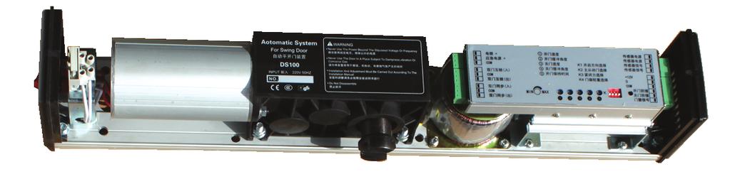


4 2 Components hole for power cable hole for sensor cable base plate power connector operator motor microcomputer controller output axis transformer cover pull arm(alternative) inward opening push arm(alternative) outward opening 2
5 3 Installation 3.1 Installation example Choose pull arm door leaf open toward inside operator is inside Choose push arm door leaf open toward outside operator is inside 3
6 3 Installation 3.2 Installation of base plate Pull arm 20 sensor cable 20 power cable As the picture show,fix the base plate on the frame with eight countersunk wood screws (if the frame is steel structure should use M6 * 15 hex countersunk head screws). At door right 20sensor cable 20power cable As the picture show,fix the base plate on the frame with eight countersunk wood screws (if the frame is steel structure should use M6 * 15 hex countersunk head screws). At door left 4
7 3 Installation 3.2 Installation of base plate Push arm 20 sensor cable 20 power cable As the picture show,fix the base plate on the frame with eight countersunk wood screws (if the frame is steel structure should use M6 * 15 hex countersunk head screws). At door right 20 sensor cable 20 power cable As the picture show,fix the base plate on the frame with eight countersunk wood screws (if the frame is steel structure should use M6 * 15 hex countersunk head screws). At door left 5
8 3 Installation 3.3 Pull arm Fix the slide rail of pull arm on the door panel as shown using three round head wood Screws (if the door panel is steel, please use M6*15 cross recessed head screws.) Adjust the opening angle by moving the stopper (The stopper is at the left side when left installation.) At door right 6
9 3 Installation 3.4 Push arm Fix the support holder of push arm on the door panel as shown using two round head wood screws (if the door panel is steel, please use M6*15 cross recessed head screws.) Loosen this three bolts and adjust the push arm length according to the door depth(l) until the angle between the push arm and door panel is 90. At door right 7
10 3 Installation 3.4 Push arm Stopper Adjust the stopper position in the U hole according to the diagram. 8


11 3 Installation 3.5 operation system Hook the operation system on the finished base plate as shown, fix it with eight hexagon socket head screws. 3.6 Cover Opening the cover 9
12 3 Installation 3.7 Connect the motor and the pull arm 3.8 Connect the motor and the push arm motor axis extend 10
13 4 Electrical connection power cable fuse 3A transformer18v motor 8-core cable controller controller motor,transformer power supply 220V factory setting,transformer 2-core cable,motor 8-core cable and controller connected. Electric lock +12V UPS +24V interlock(in) interlock(out) sync (in) sync (out) MIN Opening speed Slow opening angle Closing speed Slow closing angle Hold open time MAX K1 opening direction SEN power+24v K2 master door slector SEN power 0V K3 closed force selector sensor signal K4 arm selector sensor signal +12 V GND ON Safety SEN(open) K Safety SEN(close) Access control signal Access control+electric lock Electric+ lock - Automatically lock connection Interlock Electric lock +12V UPS +24V interlock(in) interlock(out) +12 V GND Safety SEN(open) Safety SEN(close) Access control signal Access control power Access control power + - Access control signal Access control signal If there is no remote control, to connect interlock(in) with, the door will lock automatically every time closed. Interlock(in) Interlock(out) Interlock(in) Interlock(out) Door A controller Door B controller Note:Two doors share one sensor or same signal source,two doors will keep opening. Exchange two signal wires of the sensor which connected to the same controller, the operation will be normal. Double-door synchronous Synchronous(in) Synchronous(out) Door A controller Door B controller Synchronous(in) Synchronous(out) * When double opening,open first & close second is the master door, close first & open second is slave door; Master door turn K2 down, slave door turn K2 up. * Sensors and access control system are connected to master door controller. 11
14 4 Electrical connection Sensor sensor power+24v sensor power 0V sensor signal sensor signal Safety sensor (open) Safety sensor(open) Safety sensor(close) Access control signal power signal Safety sensor(close) Safety sensor(open) Safety sensor(close) Access control signal power signal DIP ON Code card reader Safety sensor(open) Safety sensor(close) Access control signal power signal ALARM GND OPEN DOOR-1 PUSH/N.O N.C GND 12+ BEELSW 12

15 5 Parameters adjustment 1.Opening speed 2.Slow opening angle 3.Closing speed 4.Slow closing angle 5.Hold open time turn it clockwise to increase speed turn it clockwise the angle is bigger turn it clockwise to increase speed turn it clockwise the angle is bigger turn it clockwise the time is longer 1/4:7S 1/2:14S 3/4:21S set the K switch(k1-k4) after setting power off restart. K1: power on the door goes to closing direction is correct if no, change the switch position. K2: Synchronous master door: turn down, slave door: turn up(on) K3: Manual pull/push: turn down, closed force: turn up(on K4: With pull arm: turn down With push arm: turn up (ON) Electric lock +12V UPS +24V interlock(in) interlock(out) sync (in) sync (out) MIN Opening speed Slow opening angle Closing speed Slow closing angle Hold open time MAX K1 K2 K3 K opening direction SEN power+24v master door slector SEN power 0V closed force selector sensor signal arm selector sensor signal +12 V GND ON Safety SEN(open) K Safety SEN(close) Access control signal lock hold-open reset automatic encode button 1.Delete all: long press the button Encode until the sound of buzzer disappears, loosen the button. 2.Encoding: long press the button Encode, the buzzer sounds. Then press any button of the remote control, the buzzer stops sounding which means encoding successfully. When use the remote control, the buzzer sounds for 2 seconds. 3.Note: when use the remote control, if the buzzer deep twice, it means encoding failed, so please repeat above step 2. 4.Press button automatic one time, the door will open and close one time. One controller can be connected with remote control not more than 10pcs. 13

16 The Product Has Passed ISO 9001:2015 Quality Management System Certification
SWING GATE OPENER SW300 SERIES
 USER'S MANUAL SWING GATE OPENER SW300 SERIES 2.50m max. 250kg max. 2.50m max. 250kg max. Important Safety Advice: 1. Knowledge of the relevant electro-technical regulations is required. 2. Training in
Automatic Swing door Operator SD3108 Product manual. Notes: please keep the manual properly for reference. Do carefully read this manual before use.
 Automatic Swing door Operator SD3108 Product manual Notes: please keep the manual properly for reference. Do carefully read this manual before use. Safety Warning! Please read carefully the instructions
SWING GATE OPENERS 24V DC GEAR MOTOR
 SWING GATE OPENERS 24V DC GEAR MOTOR FOR RESIDENTIAL USER MANUAL Flashing Light Push Button Control box Gate 2 Gate 1 Index Warnings 2 5. Technical Characteristics 21 1. Product Description and Applications
TPMS TP200 USER S MANUAL
 TPMS TP200 USER S MANUAL V6.03.21 CONTENTS Packing List... 2 Standard Tools and Accessories... 3 Display Power On... 4 Installation of tire sensors... 5 Driving checking... 6 USB charging Socket... 6 Display
PY600AC Sliding Gate Opener User Manual
 PY600AC Sliding Gate Opener User Manual 2017 Dear users, Thank you for choosing this product. Please read the manual carefully before assembling and using it. Please do not leave out the manual if you
DLS-TP400 USER S MANUAL
 DLS-TP400 USER S MANUAL TPMS CONTENTS Safety Precautions...... 2 Packing List... 3 Standard Tools and Accessories... 4 Display Desktop Base Installation... 5 Cigarette Lighter Bracket Installation... 6
Base Kit Chain Drivetrain Build Guide
 222fg Base Kit Chain Drivetrain Build Guide August 11, 2017 Chain Drivetrain Build Guide Copyright 2017 REV Robotics, LLC 1 1.1 Description This document outlines the steps required to four wheel, chain
DL300 FINGERPRINT LOCK
 DL300 FINGERPRINT LOCK USER MANUAL Please read this manual carefully before operation. Please keep this manual for later reference. Intelligent Biometric Controls, LLC. Tel: (513) 336-9292 Fax: (513) 336-0626
GoSafe TPMS 100 USER S MANUAL. Copyright 2016, PAPAGO Inc., All Right reserved.
 GoSafe TPMS 100 USER S MANUAL Copyright 2016, PAPAGO Inc., All Right reserved. V6.05.05 CONTENTS Packing List... 2 Display Power On... 3 Sensor Installation... 4 Driving check... 5 USB charging Socket...
Z TECHNICAL INSTRUCTIONS
 ÍNDICE: Z40 2.0 TECHNICAL INSTRUCTIONS 1.- Error list 2.- Replace the control board 3.- Opening the machine 4.- Replace the power board 5.- Dismantling motor and gear box 6.- Assembly of gear box 7.- Pushing
PW320/PW330 USER MANUAL SWING GATE OPENERS 24V DC GEAR MOTOR FOR RESIDENTIAL. Flashing Light. Push Button. Control box. Gate 2.
 PW320/PW330 USER MANUAL SWING GATE OPENERS 24V DC GEAR MOTOR FOR RESIDENTIAL Flashing Light Push Button Control box Gate 2 Gate 1 Declaration of Conformity Applicant: Powertech Electronics Inc. Manufacturer:
Requirements LEO Power Operator Installation Instructions Patents: 5,881,497; 7,316,096; 7,484,333 CAUTION CAUTION WARNING
 CAUTION 80-957-00-00 (08-0) Series 570 Door Openings 85 to 0 or to 80 Adjustable Arm and Slide Track Application Maximum Hinge Side Frame Reveal to /8 (mm) Hinge (Pull) Side of Door Installation 5700 LEO
SWING GATE OPENERS 24V DC GEAR MOTOR
 SWING GATE OPENERS 24V DC GEAR MOTOR FOR RESIDENTIAL USER MANUAL Flashing Light Push Button Control box Gate 2 Gate 1 Index 1. Warnings 2 4. Technical Characteristics 16 2. Product Description 2.1 Applications
DRAWING NUMBER: GK-191-P-200-2C
 PARTS BREAK DOWN FOR A RIGID KAT LOWER HOUSING ASSEMBLY DRAWING NUMBER: GK-9-P-200-2C GK-7-005 KAT LOWER HOUSING 2 GK-7-02 WHEEL ADJUSTMENT SCREW 3 GK-0-062 3/4-6UNC HEX HEAD JAM NUT 4 GK-7-02 WHEEL ADJUSTMENT
Customer Name. Instruction for Operation. Single Head Sleever
 Customer Name Instruction for Operation Single Head Sleever Content Reload of Sleeve Roll (page 3~5) Sleeve Feeding (Page 6~7) Sleeve Sensor Positioning (Page 8~10) Holder Installation (Page 11~13) Splice
Operating manual and installation instructions ENGLISH. Electronic engine remote control. Copyright 2001 Vetus den Ouden n.v.
 Operating manual and installation instructions ENGLISH Electronic engine remote control Copyright 00 Vetus den Ouden n.v. Schiedam Holland Contents Introduction... General conditions of use... Operating....
BMS RS-485 Card/Box Quick Guide Applicable for hybrid inverter 3KW-10KW
 Thank you for purchasing RS485 card/box. This manual contains instructions and warnings that should be followed during the installation, operating and storage of the card. Please keep this manual for further
PW150/PW200 USER MANUAL SWING GATE OPENERS 24V DC GEAR MOTOR
 PW150/PW200 USER MANUAL SWING GATE OPENERS 24V DC GEAR MOTOR FOR RESIDENTIAL Flashing Light Push Button Control box Declaration of Conformity Applicant: Powertech Electronics Inc. Manufacturer: Timotion
5700 Series Power Operator Hinge (Pull) Side Mount Installation and Instruction ASSA Manual ABLOY
 Side Mount Installation and Instruction ASSA Manual ABLOY") 5700 Series Power Operator Hinge (Pull) Side Mount Installation and Instruction ASSA Manual ABLOY 80-957-000-00 (06-5) Patents 5,88,97; 7,6,096; 7,8, 6 5 0 8 7 9 Item No. Description Back plate Door Closer
5700 Series Power Operator Hinge (Pull) Side Mount Installation and Instruction ASSA Manual ABLOY 80-957-000-00 (06-5) Patents 5,88,97; 7,6,096; 7,8, 6 5 0 8 7 9 Item No. Description Back plate Door Closer
PARTS BREAKDOWN FOR HIGH AND LOW SPEED GEAR ASSEMBLIES
 PARTS BREAKDOWN FOR HIGH AND LOW SPEED GEAR ASSEMBLIES Refer to sketches on previous page. ITEM PART NUMBER DESCRIPTION QTY 120 GK-166-169 LOW SPEED GEAR TRAIN ASSEMBLY (ITEMS 121 TO 127) 121 GK-166-171
DTS SECURITY P.O.BOX 3399 EDENVALE 1610 Base plate-mounting instructions TELEPHONE
 DTS ECO 500 SLIDING GATE MOTOR INSTALLATION MANUAL DTS SECURITY P.O.BOX 3399 EDENVALE 1610 Base plate-mounting instructions TELEPHONE 086 1000 387 Spartan +2711 392 5540 (H/O) Pretoria +2712 361 5528 Alberton
Operating Instructions Type MPT 53
 Operating Instructions www.turnstiles.us Type MPT 53 Contents 1. Delivery... 2 2. Safety...3-4 3 Description and operation... 5 4. Technical Data 6 5. oundation...6-9 6. Assembly and installation...10-13
TMT Boxer 24v slider motor installation notes from EasyGate
 TMT Boxer 24v slider motor installation notes from EasyGate Install Physical Gate Stops Physical Gate Stops MUST be installed at each end of your gate. If the Limit Switch on the boxer motor fails to stop
Instruction Manual for the. E-SL 450 Series
 Instruction Manual for the E-SL 450 Series Estate Slide Summary of Functions The Estate Slide is only to be used for vehicular Slide gates in a Class I setting. Class I: A vehicular gate opener (or system)
Barrier Gate Manual. (DZX2.1 Control Board) (The third version) (Pictures for reference only, the product prevail in kind)
 (The third version) (Pictures for reference only, the product prevail in kind)") Barrier Gate Manual (DZX2. Control Board) (The third version) (Pictures for reference only, the product prevail in kind) Contents. Brief Introduction... 2. Functions and Features... 3. Technical Data...2
Barrier Gate Manual (DZX2. Control Board) (The third version) (Pictures for reference only, the product prevail in kind) Contents. Brief Introduction... 2. Functions and Features... 3. Technical Data...2
EQUIPMENT - MAIN BODY 7-1 SECTION 7 EQUIPMENT CONTENTS
 EQUIPMENT - MAIN BODY 7-1 SECTION 7 EQUIPMENT CONTENTS Engine Immobiliser System...7-1 Exterior Lights...7-2 Combination Meter...7-2 Smart Wiring System (SWS)...7-3 General Information...7-3 Functions
Rutgerson 32mm Self-tacking Jib System manual - English
 Rutgerson 32mm Self-tacking Jib System manual - English Follow these instructions to obtain maximum performance from the Rutgerson self-tacking jib system. The track has a given optimal placement that
Pure sine wave charger inverter Product Manual
 Pure sine wave charger inverter Product Manual The inverter installer must be professional, for the high pressure in the inverter, unprofessional person please do not open it. The inverter should be installed
IFC-BL02 Interface Free Controller Brushless Motor Card
 IFC-BL02 Interface Free Controller Brushless Motor Card User s Manual V1.1 Apr 2008 Information contained in this publication regarding device applications and the like is intended through suggestion only
Requirements LEO Power Operator Installation Instructions Patents: 5,881,497; 7,316,096; 7,484,333 CAUTION CAUTION WARNING
 CAUTION 80-957-00-00 (08-0) Series 570 Openings 85 to 0 or to 70 Double Lever Arm Application for Frame Reveals (76) to 7 (78mm)* Stop (Push) Side of Installation 5700 LEO Operator Installation Instructions
APOLLO Gate Operators, Inc.
 APOLLO Gate Operators, Inc. Model BA12 12 VOLT DC BARRIER ARM OPERATOR INSTALLATION MANUAL 0707 CONTENTS IMPORTANT SAFETY INSTRUCTIONS... 3 Applications... 4 Pre-Installation Checklist... 5 Operator Installation...
Engine Control System Tacho System
 Engine Control System Tacho System There are two redundant Tacho systems: System A System B Standard is: angle encoders with one reference sensor on the turning wheel (A-system) Option is sensors at the
Installing the gate post bracket with the cardboard arm template
 ......... Installing the gate post bracket with the cardboard arm template... Installing gate posts brackets and arms for Push-to-Open or Pull-to-Open gates... Connection of Power Source 240Vac or Solar...
Pro 400 OPERATION MANUAL. Pro 400 Lacer Pictured.
 Pro 400 OPERATION MANUAL Pro 400 Lacer Pictured. Table of Contents OPERATING INSTRUCTIONS Machine Preparation - Pro 400...1 Belt Preparation...3 Selecting and Installing the Proper Adapter/Comb...3 Selecting
Installing the gate post bracket with the cardboard arm template
 ......... Installing the gate post bracket with the cardboard arm template... Installing gate posts brackets and arms for Push-to-Open or Pull-to-Open gates... Connection of Power Source 240Vac or Solar...
B100S - Super Swing. Instruction Manual. Document number: B100S-C Release: V4.0 Date: May 08,2009
 B00S - Super Swing Instruction Manual Document number: B00S-C Release: V4.0 Date: May 08,009 ! WARNING This control must be adjusted/serviced by a qualified person. The service technician must be familiar
SKC400U SLIDING GATE OPENER OWNER S MANUAL
 SKC400U SLIDING GATE OPENER OWNER S MANUAL IMPORTANT SAFTEY INFORMATION Installing the SKC400U Gate Opener requires wiring of standard 110V electrical lines. This should only be performed by a trained
Automatic Filling Device
 Instruction language / no. /rev. / date US/137470/00/13-01-2004 Page 1 Automatic Filling Device GUIDANCE IN INSTALLATION AND CORRECT USE OF THE AUTOMATIC FILLING DEVICE FOR HS-TARM/BAXI BIOMASS BOILER
OPERATION MANUAL Electric Wire Wrapper TDWW501B
 OPERATION MANUAL Electric Wire Wrapper TDWW501B 4270 Airborn Drive Addison, Texas 75001 USA t. 972.248.1999 f. 972.248.1991 info@startinternational.com www.startinternational.com INTRODUCTION Thank you
 10-32 x 1/2" PAN HEAD BOLT 14 PLACES, 7 PER BRACKET # 10/12 GROUND WASHER 2 PLACES, 1 PER BRACKET # 10 FLAT WASHER 12 PLACES, 6 PER BRACKET BRACKET, P/N 520295 2 PLACES RIGHT SIDE VIEW (LEFT SIDE SIMILAR)
WESCO INDUSTRIAL PRODUCTS, INC. Heavy Duty Semi Electric Pallet Truck. Part Number:
 WESCO INDUSTRIAL PRODUCTS, INC Heavy Duty Semi Electric Pallet Truck Part Number: 273289 Note: Operator MUST read and understand these operating instructions before using this Hand Pallet Truck. Table
Sliding Gate Operator User's Manual
 Sliding Gate Operator User's Manual SL600AC. Products introduction Please read the instructions carefully before proceeding. MCU is supplied to control the gate operator. Keypad / single button interface.
Sliding Gate Operator User's Manual
 Sliding Gate Operator User's Manual PY800AC/PY00AC. Products introduction Please read the instructions carefully before proceeding. MCU is supplied to control the gate operator. Keypad / single button
CLINTON MODEL AS-870 / 870LCD
 CLINTON MODEL AS-870 / 870LCD VARIABLE SPEED DC SERVO MOTOR NEEDLE POSITIONER THREAD TRIMMER NEEDLE COOLER SERVICE MANUAL ML870LCD-A TABLE OF CONTENTS SECTION I - INTRODUCTION......................................
DFQ-1G-T Cutting machine control system. Operating Manual
 R software version:v1.0 DFQ-1G-T Cutting machine control system Operating Manual DFQ-1G-T cutting machine control system v1.0 Current length: Current speed: 000000M 000M/Min Up winding tension Up winding
YG101 SWING GATE OPENER OWNER S MANUAL
 YG101 SWING GATE OPENER OWNER S MANUAL IMPORTANT SAFTEY INFORMATION Installing the YG101 Gate Opener requires wiring of standard 110V electrical lines. This should only be performed by a trained technician.
V200 USER MANUAL SWING GATE OPENER. 100kg 1.5m. 100kg 1.5m
 V200 USER MANUAL SWING GATE OPENER 100kg 1.m 100kg 1.m Content Important Safety Advice... Content of the Kit... Connection Diagram... Installation Guide... Actuator... Control box... AC cable wiring...
APPLICATION NOTE. Labeling Machine
 Labeling Machine 1 3.3 Application to Labeling Machine 1 Description... 3 2 System plan... 3 2.1 Master axis Axis of conveyor... 4 2.2 Camshaft axis Label feeding axis... 4 2.3 Label positioning sensor...
GENUINE PARTS INSTALLATION INSTRUCTIONS
 GENUINE PARTS INSTALLATION INSTRUCTIONS 1 DESCRIPTION: 2 APPLICATION: 3 PART NUMBER(S) REQUIRED FOR INSTALLATION: Fog Lamp Kit (AL) Rogue (SV) 999F1 G2000 (Fog Lamp Kit) 4 KIT CONTENTS: Item Qty. Part
SECTION V SWITCHBOARD I 4 Engine/Gen Control Cubicles II 1 Synchronizing System III 1 Ground Detection Network IV 1 600V Feeder Section V 2
 SECTION 1. 600V SWITCHBOARD I 4 Engine/Gen Control Cubicles II 1 Synchronizing System III 1 Ground Detection Network IV 1 600V Feeder Section V 2 Soft Starters SECTION 2. LIQUID COOLED VFD I 3 Liquid Cooled
Installation & Service Manual
 Installation & Service Manual for M² Sync Slideout Control Box #1510000122 CONTENTS Introduction Installation Installation Problems Program Mode Operation Mode Preventative Maintenance Fault Diagnostics
Sliding Gate Operator. User's Manual WARNING THIS PRODUCT MUST BE INSTALLED BY A QUALIFIED ELECTRICIAN
 Sliding Gate Operator User's Manual WARNING THIS PRODUCT MUST BE INSTALLED BY A QUALIFIED ELECTRICIAN BMG Imports Sliding Gate Opener MODEL No. LW550 Power rating: 220-240v AC 50Hz 550w Duty Close: 0-120
FitBike 1 DBT. Instructions / Manual / Maintenance
 FitBike 1 DBT Instructions / Manual / Maintenance SAFETY PRECAUTIONS Please read all instructions carefully before using this product. Retain this manual for future reference. The specifications of this
CORPORATION OPERATOR S MANUAL HWH TOUCH PANEL-CONTROLLED 305/325 SERIES LEVELING SYSTEM. FEATURING: Touch Panel Leveling Control
 OPERATOR S MANUAL HWH TOUCH PANEL-CONTROLLED 305/325 SERIES LEVELING SYSTEM R HWH R CORPORATION FEATURING: Touch Panel Leveling Control R BI-AXIS Hydraulic Leveling Straight-Acting Jacks Pilot Operated
Spare parts list UC-S
 Spare parts list UC-S Contents Water inlet and tank heating Water softener Water drain, Mediamat Cyclo Circulating pump Wash + rinse; bottom Wash + rinse; top Boiler Dosage Casing Cover plate, electrical
GARAGE DOOR OPENER OWNER S MANUAL S3/S4
 GARAGE DOOR OPENER OWNER S MANUAL S3/S4 Features! Locking door during power failure: If power failure occurs while the door is operating, the door can be released by pulling the clutch down, allowing
UCHIDA STAPLER & PUNCHER SP-22 PARTS LIST
 UCHIDA STAPLER & PUNCHER SP-22 PARTS LIST 04/05/06 Screw, nuts, washers, to be used for folders Description of parts (screw,e-ring, spring pin, etc.) illustrated * Orders for screws, washers, etc. should
V1.0. Showven Technologies Co.,Ltd.
 V1.0 Showven Technologies Co.,Ltd. SONICBOOM TM SMOKEJET USER MANUAL Foreword Thanks for choosing SHOWVEN SONICBOOM TM SMOKEJET. Please read following manual carefully and completely before operating this
Fault Codes. J control
 J control Timer Temp Fault Codes 12 11 10 9 8 7 6 5 4 3 2 1 30 29 28 27 26 25 24 23 22 21 20 Enter unit inspection mode by pushing the UP and DOWN buttons simultaneously for two seconds. Ensure that the
Technical Instructions Flowrite 599 Series SKD6xU Electronic Valve Actuators 24 Vac Proportional Control Description Features Application
 Document No. 155-180P25 Flowrite 599 Series SKD6xU Electronic Valve Actuators 24 Vac Proportional Control Description The Flowrite 599 Series SKD6xU Electronic Valve Actuators require a 24 Vac supply and
Marine Exhaust Temperature Alarm. COMPONENTS
 Marine Exhaust Temperature Alarm. Model: SM010 INTRODUCTION COMPONENTS Marine water cooled exhaust systems are designed to withstand temperatures of up to about 120 C. However the exhaust gases from the
USER MANUAL LEVER LOCK DIGITAL TOUCHPAD TEMPLATE. 120x165(mm)
") 120x165(mm) Mark Ø1" (25.4mm) hole at center of door edge. 2" 1-3/4" 1-9/16" 1-3/8" 51 45 40 35 FOR ( ) 2-3/8 60mm BACKSET Fit here on door edge FOR ( ) 2-3/4 70mm BACKSET TEMPLATE Limited Warranty Statements
120x165(mm) Mark Ø1" (25.4mm) hole at center of door edge. 2" 1-3/4" 1-9/16" 1-3/8" 51 45 40 35 FOR ( ) 2-3/8 60mm BACKSET Fit here on door edge FOR ( ) 2-3/4 70mm BACKSET TEMPLATE Limited Warranty Statements
The EFL 2000/1 & 2 User Guide Test Sieve Shaker. Contents
 The EFL 2000/1 & 2 User Guide Test Sieve Shaker ISSUE 04-02 Contents Description Page 1 Setting Up: 2-8 Unpacking 2 Assembly 3 Clamping Assembly 4 Electrical Connections 5 Sieve Stacking 6 8 Operating
ADDENDUM MODEL S3 OPERATORS Models: SL/540/570/580/590 & SW420/470/490
 ADDENDUM MODEL S3 OPERATORS Models: SL/540/570/580/590 & SW420/470/490 This addendum is to be used in conjunction with the owner s manual included with this operator. Refer to this addendum for all programming
ECL Apex 10. User Guide. ECL Apex 10 *087R9745* Installation and configuration. *vijem102*
 User Guide ECL Apex 10 *087R9745* *vijem102* Installation and configuration VI.JE.M1.02 Danfoss 11/2004 DH-SMT VI.JE.M1.02 Danfoss 11/2004 DH-SMT ECL Apex 10 VI.JE.M1.02 Danfoss 11/2004 DH-SMT VI.JE.M1.02
ASSA ABLOY Series Power Operator Installation and Instruction ASSA Manual ABLOY ASSA ABLOY
 00 Series Power Operator Installation and Instruction ASSA Manual ABLOY Item No. Description Motor (00M) Cover (00COV) Control Inverter (00IN) Power Supply VDC (00PS) Track Assembly (0-) / Replacement
AR-B2020 Quick Manual V1.0
 V1.0 Connection drawing (Concept) 1. Introduction AR-B2020 is a cost effective power control board with the basic power control function for AR-V5430FL In-Vehicle computer. With PHET C-LiFePO4 12V 4.8Ah
7 Lighting Technology
 7 Lighting Technology Sheet-Steel Emergency Light Fitting 09361E00 and 6418 (Zones 2, 21 and 22) emergency light fittings in sheet-steel can be used for safety illumination, especially in spraying and
TEL: G&C Electronics CC E. T.
 TEL: +27 21 448 6774 G&C Electronics CC FAX: +27 21 447 7794 E. T. CK 89/31531/23 E-mail : etsystems@icon.co.za Internet: www.et.co.za 15 Nelson Road P.O. Box 34524 Observatory Groote Schuur Cape Town
Ditec PWR Automation system for swing gates with wings up to 5 metres
 SAFE 24 V VIRTUAL ENCODER EASY TO INSTALL COMPLETE RANGE Ditec PWR Automation system for swing gates with wings up to 5 metres EN www.entrematic.com Ditec PWR a complete range Ditec PWR is the new range
ACSI MODEL 1406BB-04-AO POWER SUPPLY INSTALLATION INSTRUCTIONS
 II 1400-10 ACSI MODEL 1406BB-04-AO POWER SUPPLY INSTALLATION INSTRUCTIONS Features: Up to 1.95 Amps Load Capacity Class 2 Rated Outputs Overload, Over Voltage, and Short Circuit Protection Standby Battery
CENTROIDTM. AC Brushless Drive. Product Spec Sheet
 4 Axis, up to 2 KW motors Brake Output for each axis Overtemp and Overcurrent Protection All-software Configuration Self-cooled Fiber Optic Control CENTROIDTM AC Brushless Drive Product Spec Sheet AC Brushless
Automatic Operator for swinging doors
 Automatic Operator for swinging doors I N S T A L L A T I O N I N S T R U C T I O N Installation Instruction 2 Installation Instruction Index Technical specifications... page 5 Automatism installation
Hinge Wing Safety Interlock Switches
 Hinge Wing Safety Interlock Switches SI-HG80 Series Safety Interlock Switches Encapsulated in a Load-Bearing Hinge Inline QD Fitting Right-Angle QD Fitting Features Safety switch is integrated and encapsulated
CAUTION DO NOT ATTEMPT TO ALTER THE TUNING OF THE RADIO EQUIPMENT. DO NOT USE RADIO CONTROL EQUIPMENT IN THUNDERSTORMS.
 P.O Box 578 Casino, NSW, 2470 Australia Phone: International ++614 2902 9083 Australia (04) 2902 9083 Website: http://rcs-rc.com E mail: info@rcs-rc.com TX-3 Digital Proportional R/C TABLE OF CONTENTS
Instruction Manual Installation and Operation Guidelines for DWL5000XY and DWL5500XY Tilt Sensor Modules (Version 2.2)
") Instruction Manual Installation and Operation Guidelines for DWL5000XY and DWL5500XY Tilt Sensor Modules (Version 2.2) INTELLECTUAL PROPERTY This manual contains propriety information, which is protected
Instruction Manual Installation and Operation Guidelines for DWL5000XY and DWL5500XY Tilt Sensor Modules (Version 2.2) INTELLECTUAL PROPERTY This manual contains propriety information, which is protected
ASTRO ATS-309 TABBER/STAMP AFFIXER
 ASTRO ATS-309 TABBER/STAMP AFFIXER PARTS CATALOG This manual is intended solely for the use and information of Astro Machine Corp., its designated agents, customers, and their employees. The information
Sieve Shaker 200mm/300mm - 8/12 inch SV003
 Sieve Shaker 200mm/300mm - 8/12 inch SV003 CONTENTS Introduction Specification Installation Controls Operation Maintenance Spares and Accessories 1 Introduction The unique action of this Sieve Shaker (Fig
AMCON AUTOMATIC CHART PROJECTOR USER S MANUAL EQ-6002
 AMCON AUTOMATIC CHART PROJECTOR USER S MANUAL EQ-6002 1-800-255-6161 Fax 1-800-397-0013 www.amconlabs.com Disclaimer...2 1. Introduction...3 2. Safety Instructions......3 3. Charts and Specifications......4
TX-1 Digital Proportional R/C
 P.O Box 578 Casino, NSW, 2470 Australia Phone: International ++614 2902 9083 Australia (04) 2902 9083 Website: http://rcs-rc.com E mail: info@rcs-rc.com TX-1 Digital Proportional R/C TABLE OF CONTENTS
USER'S GUIDE and Spare Parts Drawings GENERIC APPLICATIONS
 Super ELF-X2 USER'S GUIDE and Spare Parts Drawings GENERIC APPLICATIONS SUPER ELF X2 WARNING! - Condensation could form on the Weft Feeder when it is moved from the cold environment of the warehouse to
INSTALLATION INSTRUCTIONS
 DENTAL CHAIR INSTALLATION INSTRUCTIONS IMPORTANT This manual provides installation instructions for BELMONT PROGRES. The instructions contained in this booklet should be thoroughly read and understood
EstateSwing.com. Plug-in Option. E-S 1000H Series INSTRUCTION MANUAL
 EstateSwing.com Plug-in Option E-S 1000H Series INSTRUCTION MANUAL Estate Swing Summary of Functions The Estate Swing is only to be used for vehicular swing gates in a Class I setting. Class I: A vehicular
TECHNICAL INFORMATION
 TECHNICAL INFORMATION Model No. Description DP4010, DP4011 2-Speed Drill 13mm (1/2") L PRODUCT P 1/ 8 CONCEPT AND MAIN APPLICATIONS Models DP4010 and DP4011 have been developed as 13mm (1/2") Drill for
BMW 745Li E65/E66 Rear Brake Pad Replacement By Jerry Incollingo (Jerry 745Li)
") Page 1 of 11 BMW 745Li E65/E66 Rear Brake Pad Replacement By Jerry Incollingo (Jerry 745Li) This guide will detail how to change the rear brakes on late model BMW E65 / E66 s. It was performed on a 2003
Page 1 of 11 BMW 745Li E65/E66 Rear Brake Pad Replacement By Jerry Incollingo (Jerry 745Li) This guide will detail how to change the rear brakes on late model BMW E65 / E66 s. It was performed on a 2003
 YNCHRONIZER AUTOMATIC SYNCHRONIZE TROUBLESHOOTING GUIDE SOLENOID (MODEL 1750) RELAY ASSEMBLY LIMIT SWITCH ENGINE CABLE CABLE TO ENGINE THROTTLE RED COLLAR ADJUST LIMIT SWITCH OPERATION BRIDGE CABLE CONTROL
NT-500 Technical Support Guide. For use by qualified company approved Technicians
 NT-500 Technical Support Guide For use by qualified company approved Technicians INTRODUCTION The NT-500 is designed to offer the full range of features required to perform radiofrequency denervation The
Low Voltage Disconnect, Sure Power 54.18
 Low Voltage Disconnect, Sure Power 54.18 Functional Test NOTE: If the LVD deactivates (removes power to the cab/sleeper loads), it needs to be reset prior to performing a functional test. If the batteries
METROLOGIC INSTRUMENTS, INC. MX001 Industrial Control Interface Installation and User s Guide
 METROLOGIC INSTRUMENTS, INC. MX001 Industrial Control Interface Installation and User s Guide Copyright 2007 by Metrologic Instruments, Inc. All rights reserved. No part of this work may be reproduced,
Linear Alignment. motion. 2 Flexible combination of XY. 4 High resolution and high responsiveness. accuracy. Optical linear encoder scale head
 SADE SADE/X SADE/S 2 2 Alignment Stage SA Linear motor drive SA DE Crossed roller bearing -table Linear Alignment Points 1Compact XY-table motion. Using a Linear Way L miniature linear motion rolling guide
SYNCHRONIZE YNCHRONIZER AUTOMATIC TIC TROUBLESHOOTING GUIDE RELAY ASSEMBLY SOLENOID (MODEL 1750) LIMIT SWITCH ENGINE CABLE CABLE TO
 LIMIT SWITCH ENGINE CABLE CABLE TO") YNCHRONIZER SYNCHRONIZE AUTOMATIC TIC TROUBLESHOOTING GUIDE SOLENOID (MODEL 1750) RELAY ASSEMBLY LIMIT SWITCH ENGINE CABLE CABLE TO ENGINE THROTTLE RED COLLAR ADJUST LIMIT SWITCH OPERATION BRIDGE CABLE
YNCHRONIZER SYNCHRONIZE AUTOMATIC TIC TROUBLESHOOTING GUIDE SOLENOID (MODEL 1750) RELAY ASSEMBLY LIMIT SWITCH ENGINE CABLE CABLE TO ENGINE THROTTLE RED COLLAR ADJUST LIMIT SWITCH OPERATION BRIDGE CABLE
GATES-ELECTRIC AND MECHANICAL SELF CLOSING 2000 SERIES
 2014 GATES-ELECTRIC AND MECHANICAL SELF CLOSING TURNSTILE SECURITY SYSTEMS Inc. THIS CATALOGUE IS MEANT AS REFERENCE MATERIAL FOR TURNSTILE SECURITY SYSTEMS Inc. FOR THE SOLE PURPOSE OF INFORMING POTENTIAL
NV Direct Coupled Globe Valve Actuator
 70396 Rev. C Non-spring return, on/off, floating point, proportional control NV Direct Coupled Globe Valve Actuator NV24-3 US NVD24-3 US NV24-MFT US NVD24-MFT US Application For on/off, floating point
Safety Precautions Product Contents Product PIN Diagram LED indicators Product Dimensions Installation of Panel with Casing Wire Legend Power Wiring
 www.zkteco.com Safety Precautions Product Contents Product PIN Diagram LED indicators Product Dimensions Installation of Panel with Casing Wire Legend Power Wiring Diagram FR1200 Connection Weigand Connection
AL625 & AL625HD INSTALLATION & OWNER S MANUAL
 AL625 & AL625HD INSTALLATION & OWNER S MANUAL These instructions are provided to assist you in the installation of the AL625. If you require further assistance, our trained staff is ready to provide you
Installation and Service Manual M² Sync Room Slideout System without Room Lock Connectors on Control Box
 Installation & Service Manual M² Sync Room Slideout System w/o Room Locks: for Slideout Control Box# 1510000143 and 1510000198 Figure 1 01/13 Power Gear #3010002088 Rev. 0C Installation and Service Manual
DJI E800 Multirotor Propulsion System
 DJI E800 Multirotor Propulsion System User Manual V1.0 2015.01 Disclaimer Thank you for purchasing the E800 (hereinafter referred to as product ). Read this disclaimer carefully before using this product.
TorqBee. EC² version with redundant measurement technology Innovation is our passion
 High - System - Technik Screwdriver with torque & angle of rotation sensor Programmable screwdriver with shut-off clutch TorqBee Pistol-, straight-, and angle screwdrivers From battery screwdriver with
PAGE. 20. Connecting an intercom.
 PAGE C0NTENTS 2. Introduction. 2. Warnings. 2. Specifications. 3. General information. 3. Terms and definitions. 4. Installation. 5. Pedestal mount. 6. Pedestal mount inward swing. 7. Pedestal mount outward
GENUINE PARTS INSTALLATION INSTRUCTIONS
 GENUINE PARTS INSTALLATION INSTRUCTIONS 1 DESCRIPTION: 2 APPLICATION: 3 PART NUMBER(S) REQUIRED FOR INSTALLATION: Fog Lamp Kit Rogue w/ AL 999F1 G2000 (Fog Lamp Kit) 4 KIT CONTENTS: Item Qty. Part Description