INSTALLATION & OPERATION MANUAL. Fan Powered Terminals VAV TERMINALS. Redefine your comfort zone.
|
|
|
- June Barrett
- 6 years ago
- Views:
Transcription


1 INSTALLATION & OPERATION MANUAL Fan Powered Terminals VAV TERMINALS
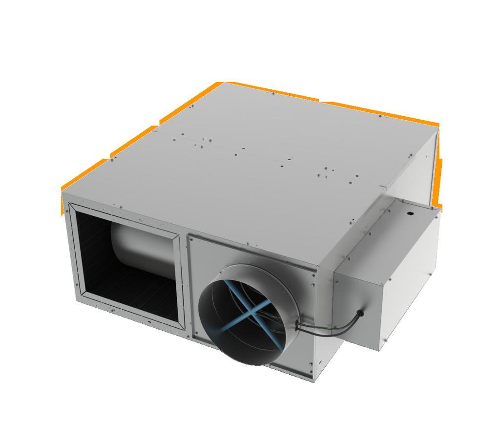
2 IOM FAN POWERED TERMINALS Receiving Inspection After unpacking the terminal, check it for shipping damage. If any shipping damage is found, report it immediately to the delivering carrier. Store units in a clean dry location and do not stack more than four high. Also, inspect damper rotation of the unit by rotating the damper by hand to check for free movement, and ensure there is no damage or binding of the damper. If controls are connected to the damper, release the manual clutch (most controls are equipped with this) and rotate the damper by hand. If there is any restriction to the rotation of the damper, contact your Titus rep and inform them of this issue. Caution: Do not use the inlet collar, damper shaft, flow sensor or air tubing as a handle to lift or move assembly. Damage to the unit or controls may result. Before installation, remove fan packing and all foreign material from the unit. Check the blower wheel for free rotation. 2 IOM - FAN POWERED TERMINALS
3 Supporting the Assembly Suspend the unit from the building structure in a horizontal plane with the access panels facing downward. Do not obstruct the access panels with support channels or straps. One inch long sheet metal screws can be used to penetrate the casing (see Figure 1). Use the support method prescribed for the rectangular duct on the job specifications. Unit may be equipped with optional hanging brackets (see Figure 2). Hanger rod up to 7/16 diameter may be used. Note: If equipped with pneumatic controls, or unit is parallel fan type (Model TQP or FLP), the terminal must be mounted right side up. It must be level within ±10 degrees of horizontal, both parallel to the air flow and at the right angle of air flow. The control side of the terminal is labeled with an arrow indicating UP. Figure 1 Figure 2 IOM - FAN POWERED TERMINALS 3
4 IOM FAN POWERED TERMINALS Duct Connections The diameter of the inlet duct D in inches must be equal to the listed size of the terminal; e.g. a duct that actually measures 8 inches must be fitted to a size 8 terminal. The inlet collar of the terminal is made 1/8 smaller than listed size in order to fit inside the duct (see Figure 1). Important: Do not insert duct work inside the inlet collar of the assembly. Inlet duct should be installed in accordance with SMACNA guidelines. Rectangular discharge opening is designed for flanged duct connections. Fasten and seal by method prescribed in the job specification. If single-point electronic velocity sensor is used, 3 to 5 inlet duct diameters of straight duct should be provided at the terminal inlet. Minimum Access Fan Powered terminals require sufficient clearance to service the fan blower assembly and internal actuator (if so equipped) from the bottom of the unit, low voltage controls from the side of the unit, and line voltage motor controls or electric heat section (if so equipped) from the rear or discharge of the unit. For bottom access panel removal, 3 minimum vertical clearance below the unit is required, plus sufficient horizontal clearance to slide the access panel clear of the bottom of the unit. Horizontal clearance is dependent on access panel dimensions as indicated on product submittals. For low voltage control enclosure access, a minimum of 18 is recommended. Specific control enclosure location is indicated on product submittals. Panel for low voltage enclosures are removable (not hinged). For line voltage motor controls or electric heat control access, a minimum of 36 should be provided to allow full opening of hinged access doors. Specific location is indicated on product submittals. Important: These recommendations do not preclude NEC or local codes that may be applicable, which are the responsibility of the installing contractor. 4 IOM - FAN POWERED TERMINALS


5 Field Wiring All field wiring must comply with the local codes and with the National Electrical Code (ANSI/NFPA ). Disconnect switches are optional equipment. Electrical, control, and piping diagrams are shown on the exterior labeling or on a diagram on the inside of the control and high voltage enclosure covers. Unless specified otherwise in the order writeup, all units are wired for a single point electrical connection to the fan and optional electrical heater. All electric heaters if provided by TITUS are balanced by kw per stage. The installing electrician should rotate incoming electric service by phase in order to help balance the building electric load. Caution Electrical Requirement: 1. Provide a safety disconnect per NEC , 20 & Disconnect all incoming power before wiring or servicing unit. All disconnect switches on the terminal (if so equipped) should be in OFF position while making power connections. 3. All field wiring must be in accordance with NEC and local code requirements. All units with electric heat should have copper wires for 125% of Nameplate Amperage. 4. Observe wiring diagram and instructions mounted on the unit. 480 V/3 phase units require a 4th (neutral) wire in addition to the full sized ground wire. All units must be grounded as required by NEC and 250. Unit Labeling Each unit will have two main labels attached to the casing. The FAN UNIT label (Figure 3) lists the Model Number, Supply Voltage requirements, Motor Horsepower, and Overcurrent Protection requirements. The AIR FLOW label (Figure 4) lists the Model Number, Unit Size, Factory Order Number, and Location. The Location (or Tag ) indicates the engineer s planned location for the unit to be installed. There may be other labels attached to the unit, as options or codes may require. Please read all labels on a typical unit, before beginning installation. If you have any questions, please contact the local TITUS Representative for clarification. Have the key points from the Air Flow label available for reference before calling. IOM - FAN POWERED TERMINALS 5
6 IOM FAN POWERED TERMINALS Primary Air Damper TFS, TQS and TQP Models To replace the damper blade and/or shaft assemblies: a. Disconnect power before servicing. Remove control enclosure cover to access actuator. b. Note position of damper shaft, using indicating arrow. Loosen linkage or actuator collar to allow damper to rotate freely. c. Remove bottom access door to expose damper assembly. Rotate damper to fully closed position, exposing rivets holding damper blade to shafts. e. Fit new damper and/or shaft assemblies in place, using 1/4-20 screws with lock nuts to replace rivets. f. Reverse procedure in steps c, b, and a, for assembly. When locking down actuator linkage or collar, position indicating arrow on damper in the same location as before the repair. FLS and FLP Models These units use an opposed blade damper assembly that is not repairable. The entire assembly must be replaced. d. Drill out rivets using 1/2 drill, rotate damper to fully open position, and slide damper and/or shaft assemblies out of the duct. Standard PSC Motor Fan Flow Adjustment Note: Before starting fan motor, follow steps 1 and Discharge ductwork should be connected. The minimum recommended discharge static pressure is 0.2 wg. Be sure fan packing is removed from units with fan packing! 2. All foreign materials should be removed from duct system. Filters should be installed where required. 3. Standard PSC motors are shipped from factory at full speed setting. Allow motor to run-in at least 15 minutes before adjusting speed. During initial run-in, check ductwork connections for leaks and repair if necessary. (Do not adjust fan speed down if ductwork is not connected). 4. Unit is equipped with manual fan speed control, mounted on the bottom of the line voltage motor enclosure or electric heat enclosure. Turning the control counterclockwise will reduce the fan speed; clockwise will increase speed. 5. Set the unit to full heating (maximum induction). Adjust and set remote balancing dampers, if present. Adjust the speed control to deliver the required CFM by measuring air quantity at the room outlets. 6. Proceed to primary air adjustment procedure, detailed in control installation information. Fan should be re-adjusted with primary air and ventilation air at maximum setpoint, to insure that no supply air is discharged at the induction port. 6 IOM - FAN POWERED TERMINALS
7 ECM Motor Fan Flow Adjustment Note: Before starting fan motor, follow steps 1 and Discharge ductwork should be connected. The minimum recommended discharge static pressure is 0.2 wg. Be sure fan packing is removed from units with fan packing! 2. All foreign materials should be removed from duct system. Filters should be installed where required. 3. PWM Fan Speed Controller a. ECM motors with manual PWM controllers are shipped from factory at design CFM when provided. Otherwise motors are shipped at motor full speed setting. b. ECM motors shipped with remote PWM controller require a signal from the DDC controller to control fan speed. (See page 4 for operating instructions for remote pwm.) c. Allow motor to run-in at least 15 minutes before adjusting speed. During initial run-in, check ductwork connections for leaks and repair if necessary. (Do not adjust fan speed down if ductwork is not connected). 4. ECM unit is equipped with either a manual control or a remote control PWM fan speed controller, mounted on the bottom of the line voltage motor enclosure or electric heat enclosure. a. The manual PWM controller has a screwdriver dial adjust pot and an LED readout. The LED display shows the flow index when the screwdriver adjust is turned. The flow index is a number from which correlates to a CFM shown in the PWM calibration table. Use the screwdriver adjust to set the CFM of the unit. b. Remote PWM controllers require a signal from the DDC controller to control fan speed. An increase in DDC voltage signal from 0-10Vdc correlates linearly to the flow index shown in the PWM calibration table. A green lamp continuously flashes to indicate the flow index value. Long flashes represent the tens digit and short flashes represent the units digit of the flow index. 5. Set the unit to full heating (maximum induction). Adjust and set remote balancing dampers, if present. Adjust the speed control to deliver the required CFM by measuring air quantity at the room outlets. 6. Proceed to primary air adjustment procedure, detailed in control installation information. Fan should be re-adjusted with primary air and ventilation air at maximum setpoint, to insure that no supply air is discharged at the induction port.maintenance Procedures:Fan and MotorMotor is equipped with permanently lubricated bearings. Inspect fan and motor assembly for accumulation of dust and dirt as required by operating environment. Clean as necessary. If fan motor does not run: a. Free rotation of blower wheel fan packing removed. Freight or installation damage. b. Check for proper unit power Disconnects should be ON.Check optional fusing. c. Check for proper control signal, P/E switch setting, proper air control 24 Vac at fan contactor, coil energized. If fan motor runs, excessive noise: a. Clearance problems on blower. All components securely attached. b. Verify integrity of ductwork. Leaks or loose connections. Rattling diffusers or balancing dampers. c. Maximum CFM too high, or discharge static pressure too low If fan motor runs, insufficient air flow: a. Check for ductwork restrictions. Dirty air filters. Clogged water coils. b. Re-adjust fan speed control. c. Discharge static pressure too high. If repair or replacement is required: Motor and fan should be removed as an assembly. Disconnect all power before servicing. Remove the hex nuts from the mounting lugs holding the fan assembly to the discharge panel, and lower the assembly. For model TFS, lift the motor / blower assembly to release the tabs from the discharge panel, then lower the assembly. Do not allow assembly to hang from wiring. If removing motor from blower, first loosen the set screw holding the blower wheel to the motor shaft. Remove the three screws holding motor to the fan housing, and slide motor and fan housing apart. Reverse the procedure for assembly. Note: Over tightening motor mounting screws may crush isolation bushings, causing excessive fan noise. IOM - FAN POWERED TERMINALS 7
8 IOM FAN POWERED TERMINALS Optional Water Coil Cleaning In most cases, the supply side of the water coil (optional) can be cleaned by removing the bottom access door and cleaning the coil face through the open space between the motor / blower assembly and the unit casing.if more space is desired to clean the water coil, the motor / blower assembly may be removed and reinstalled as described above. Remote PWM Speed Please note remote PWM shall be set via BMS...any attempt to balance locally will be reset via BMS overide. The remote PWM controller has a manual adjust potentiometer that allows the user to override the automation signal for 15 minutes, if the automation signal is less than 0.1VDC. This feature, allows heat to be used during construction and achieve air balancing before the automation is installed. However, if the automation is connected and available, automation tools should be used to balance the air. 8 IOM - FAN POWERED TERMINALS

9 Steps for Air Balance AUTOMATION AIR BALANCE If Automation is already installed, air balance can be achieved using automation tools. Please notice that a control signal less than 0.2Vdc may put the ACU+ into manual override. Avoid setting the automation signal to less than 0.2Vdc. Caution: turning Adjust locks out the automation signal for 15 minutes. Cycle power for faster lockout removal. MANUAL AIR BALANCE The ACU+ can be manually adjusted before automation is available. The balancer s manual adjustment has authority until automation is connected. Air Balancer: 1. Use Adjust to set the air flow. This adjustment will have authority for at least 15 minutes. 2. Read the flashing green light and record the flow index on the air balance report. Automation Integrator: 1. Set the Signal to 0Vdc to invoke manual override. 2. Record the RPM on the air balance report. 3. Enter the flow index the air balancer entered on the air balance report. 4. Observe the RPM is at or near the RPM observed in step Cycle the motor on/off 5 times. This clears the manual override function unless the M jumper is in place. IOM - FAN POWERED TERMINALS 9
10 IOM FAN POWERED TERMINALS Replacement Parts List Description Part Number Description Part Number Multipoint Velocity Sensors Size Size Size Size Size Size Damper Shaft Extension Short Stub All Sizes Long Ext. Sz 6,14, Long Ext. Sz 8,10, Shaft Bearing All Primary Damper Assembly (TFS,TQS,TQP) Size Size Size Size Size Size Primary Damper Assembly (FLS, FLP) Sizes 2, Size 4 FLS Size 4 FLP Induced Air Filters Model TFS B,C 16x D,E 14x Model TFS-F Fantom IQ B,C 11x D,E 18x Model TQS, TQP2, 3,4 19x ,6,7 27x Model FLS 2,3,4 10x Filter Bracket Universal Filter Clip, Wire Control Tube Red Stripe.25 O.D Green Stripe.25 O.D Red Stripe.38 O.D Green Stripe.38 O.D Tees for Sensor Taps Plastic Plastic Plugs for Tees 0.25 (1/4 ) (3/8 ) Fan Motor Fuse (SC-CL-G 300V) 1 Amp Amp Amp Amp Amp Amp Amp Amp Amp Disconnects Fan Toggle Door Interlock 3P/30A Door Interlock 3P/60A Door Handle Adapter Kits Door Interlock 3P/30A Door Interlock 3P/60A Fan Relays 1 Pole, 24V Coil Pole, 24V Coil Model FLP 2,4 18x IOM - FAN POWERED TERMINALS
11 Replacement Parts List (continued) Description Part Number Description Part Number Contactors, Magnetic 2P/20A, 24V coil P/20A, 120V coil P/20A, 208/240V coil P/20A, 277V coil Safety Devices Auto Reset Thermal Cutout for Elec. Coils Air Flow Switch (AFS) AFS Sensor 4 length AFS Sensor 6 length P.E. Switch, 1 step P.E. Switch, 2 step P.E. Switch, 3 step Control Transformers 120/24V, 50 VA /240/24V, 50 VA /24V, 50 VA Hanger Brackets TFS TQS, TQP, FLS, FLP ECM Motor Components ECM Motor Mounting Assembly Includes: Motor Belly Band Grommet Set (3) Nut, ¼ - 20 x 1½ Hex Bolt ¼ x ¾ ¼ x ¾ Screw (3) Washers (4) PWM (Manual Operation) PWM (Remote Operation) V Power Cable, 8 ft V Power Cable, 5 ft V Comm. Cable, 8 ft V Comm. Cable, 5 ft V Power Cable, 8 ft V Power Cable, 5 ft Power Filter (1 hp) Power Filter (½, 1/3 hp) Fan Speed Controllers (SCR) 120V /240V V Fan Motor Capacitors (120V, 208/240V, 277V) 1/10 Hp Motor 4 MFD /6 Hp Motor 4MFD /4 Hp Motor 5 MFD /3 Hp Motor 10 MFD /2 Hp Motor 10 MFD /4 Hp Motor 20 MFD Hp Motor 25 MFD Mounting Bracket (all) IOM - FAN POWERED TERMINALS 11
12 IOM FAN POWERED TERMINALS Replacement Parts List (continued) FAN MOTORS & BLOWERS Model Unit Size HP 120V/1 208/240V/1 277V/1 Blower Assembly TFS, TFS-F Left Hand Unit TFS, TFS-F Right Hand Unit TQS TQP FLS FLP A 1/ B 1/ C 1/ D 1/ E 3/ B 1/ C 1/ D 1/ E 3/ / / / / / N/A / / / / / / / / / / IOM - FAN POWERED TERMINALS
13 Replacement Parts List (continued) ECM FAN MOTORS & BLOWERS Model Unit Size 1HP 120V/1 208/240V/1 277V/1 Blower Assembly TFS w/ecm Motor Left Hand Unit TFS w/ecm MotorRight Hand Unit TFS-F w/ecm MotorLeft Hand Unit TFS-F w/ecm Motor Right Hand Unit TQS w/ecm Motor TQS w/ultraloc w/ ECM Motor TQS-IAQ w/ecm Motor TQS-IAQ & UltraLoc w/ ECM Motor FLS w/ ECM Motor TQP w/ ECM Motor A 1/ B 1/ C 1/ D 1/ E 3/ B 1/ C 1/ D 1/ E 3/ B 1/ C 1/ D 1/ E 3/ B 1/ C 1/ D 1/ E 3/ / / / / / CW 1/ CCW 1/ / IOM - FAN POWERED TERMINALS 13
14 IOM FAN POWERED TERMINALS Notes 14 IOM - FAN POWERED TERMINALS
15 Notes IOM - FAN POWERED TERMINALS 15

16 605 Shiloh Rd Plano TX ofc: fax:
Products for Indoor Air Quality and Control
 Products for Indoor Air Quality and Control Constant Volume Fan Powered Units AC_J Series ECM Motor Technical Guide Page 1 Table of Contents General Information Page Number ECM Motor Introduction 3 Design
MODELS SGX AND SSX SINGLE DUCT ROUND AIR TERMINALS
 BY JOHNSON CONTROLS INSTALLATION OPERATION & MAINTENANCE MODELS SGX AND SSX SINGLE DUCT ROUND AIR TERMINALS New Release Form ET130.13-NOM4 (908) In conjunction with the use of these instructions, obtain
Installation and Operation Manual Underfloor Fan Powered Terminal Units Model Series: 38F and 38S
 Installation and Operation Manual Underfloor Fan Powered Terminal Units Model Series: 38F and 38S Receiving Inspection After unpacking the terminal unit, check it for shipping damage. If any shipping damage
MODELS TSX AND TSX-S SINGLE DUCT ROUND AIR TERMINALS
 MODELS TSX AND TSX-S SINGLE DUCT ROUND AIR TERMINALS INSTALLATION OPERATION & MAINTENANCE New Release Form 130.13-NOM4 (908) In conjunction with the use of these instructions, obtain and refer to the construction,
Fan Powered Low Profile Variable Volume Terminal Units
 MANUAL INSTALLATION Fan Powered Low Profile Variable Volume Terminal Units FEVLP / FPVLP / FDVLP Series v001 Issue Date: 07/19/16 07/19/16 Price Industries Limited. All rights reserved. TABLE OF CONTENTS
FAN POWERED TERMINAL UNITS
 Benefits: Fan powered terminals are typically used for heating and cooling of perimeter zones. Operating cost savings can be achieved through the use of waste heat recovery from the ceiling plenum and
ATU PRODUCT CATALOG AIR TERMINAL UNITS FCI-600 CONSTANT VOLUME FAN TERMINAL UNIT Metal Industries, Inc.
 ATU PRODUCT CATALOG AIR TERMINAL UNITS FCI-600 CONSTANT VOLUME FAN TERMINAL UNIT 15 Metal Industries, Inc. BENEFITS: Fan powered terminals are typically used for heating and cooling of perimeter zones.
FAN POWERED TERMINAL UNITS
 Benefits: Fan powered terminals are typically used for heating and cooling of perimeter zones. Operating cost savings can be achieved through the use of waste heat recovery from the ceiling plenum and
SECTION AIR TERMINAL UNITS
 SECTION 23 36 00 AIR TERMINAL UNITS PART 1 - GENERAL 1.1 SUMMARY A. Section includes constant volume terminal units, variable volume terminal units, dual duct terminal units, fan powered terminal units,
FAN POWERED SERIES FCI-600 CONSTANT VOLUME FAN TERMINAL UNIT SPECIFIABLE FEATURES
 FAN TERMINAL UNIT SPECIFIABLE FEATURES Galvanized steel casing, mechanically sealed for low leakage construction NEMA TYPE 1 rated hinged control enclosure with standoff to prevent penetration of casing
INSTALLATION & OPERATION MANUAL
 INSTALLATION & OPERATION MANUAL FAN POWERED CHILLED WATER (DOAS) TERMINAL UNIT MODEL: 33SZ 9/18 IOM-DOAS Page 1 of 8 CONTENTS General...3 Receiving Inspection Checklist...3 Safety Precautions...3 Installation...3
AIR FLOW SOLUTIONS. MODEL QST Quiet, Series (Continuous) Flow VAV Terminal Unit. MODEL QPT Quiet, Parallel (Intermittent) Flow VAV Terminal Unit
 Flow VAV Terminal Unit. MODEL QPT Quiet, Parallel (Intermittent) Flow VAV Terminal Unit") IOM 002 Effective 4/06 AIR FLOW SOLUTIONS Installation, Operation, & Maintenance MODEL QST Quiet, Series (Continuous) Flow VAV Terminal Unit MODEL QPT Quiet, Parallel (Intermittent) Flow VAV Terminal Unit
IOM 002 Effective 4/06 AIR FLOW SOLUTIONS Installation, Operation, & Maintenance MODEL QST Quiet, Series (Continuous) Flow VAV Terminal Unit MODEL QPT Quiet, Parallel (Intermittent) Flow VAV Terminal Unit
TSS Single-Duct VAV Terminals
 TSS Single-Duct VAV Terminals Model TSS construction features Standard Construction Mechanical-lock construction ensures lowest possible casing leakage Roll-formed inlet collar with integral stiffening
MANUAL INSTALLATION. Venturi FX. VFX Series. v100 Issue Date: 11/22/ Price Industries Limited. All rights reserved.
 MANUAL INSTALLATION Venturi FX VFX Series v100 Issue Date: 11/22/16 2016 Price Industries Limited. All rights reserved. TABLE OF CONTENTS Product Overview Safety Precautions... 1 Caution to Contractors...1
University of Delaware
 SECTION 23 36 00 _ SUMMARY PART 1 GENERAL 1.1 SUMMARY A. Section Includes: 1. Constant/Variable volume supply terminal units. 2. Fan powered terminal units. 3. Exhaust valves B. Related Sections: Section
Daikin McQuay. VAV Air Terminal Unit MQ FCI6, FVI5, THI5. Replacement Parts List No Revision J 07/2017
 Replacement Parts List No. 700020000 Revision J 07/2017 Daikin McQuay VAV Air Terminal Unit MQ FCI6, FVI5, THI5 To find your Daikin Applied parts distributor, call 1-800-377-2787 or visit www.daikinapplied.com
ATP-2040 Electric Damper Actuator/Transmitter
 ATP-2040 Electric Damper Actuator/Transmitter Kit Includes 1. Actuator/Transmitter package: factory assembled Actuator (EDA-2040) and Transmitter (DPT-2000). Product Code Number Coupler Size Differential
SDL Single-Duct, Low-Height, VAV Terminals
 SDL -Duct, Low-Height, VAV Terminals SDL -Duct, VAV Terminals: Fit more comfort in less space Owners SDL terminals offer the typical benefits provided by single-duct units, while performing at extremely
IOM 002 Effective 12/17 A I R D I S T R I B U T I O N M O D E L Q S T M O D E L Q P T M O D E L E S T
 IOM 002 Effective 12/17 A I R D I S T R I B U T I O N A I R F L O W S O L U T I O N S I n s t a l l a t i o n, O p e r a t i o n, & M a i n t e n a n c e M O D E L Q S T Q u i e t, S e r i e s ( C o n
Submittal DIMENSIONS SIZE FAN SIZE L W H C D E F G J K [406] [508] 25 [635] [406] 16 [406] 16 [406] 39-1/2 [1003] 44-1/2 [1130] 51 [1295] 59 [1499]
![Submittal DIMENSIONS SIZE FAN SIZE L W H C D E F G J K [406] [508] 25 [635] [406] 16 [406] 16 [406] 39-1/2 [1003] 44-1/2 [1130] 51 [1295] 59 [1499]](/thumbs/94/122284584.jpg "Submittal DIMENSIONS SIZE FAN SIZE L W H C D E F G J K [406] [508] 25 [635] [406] 16 [406] 16 [406] 39-1/2 [1003] 44-1/2 [1130] 51 [1295] 59 [1499]") BC--1.0 03-01-1 Belt Drive Blower Coil Unit, Basic Unit Discharge ARGT. 1 4. See page 1 for filter rack details. 5. Base rail is optional on he base unit. See page 13. Base rails must be used with mixing
BC--1.0 03-01-1 Belt Drive Blower Coil Unit, Basic Unit Discharge ARGT. 1 4. See page 1 for filter rack details. 5. Base rail is optional on he base unit. See page 13. Base rails must be used with mixing
SINGLE DUCT VAV TERMINALS MODELS TSS & TSL TSS TSL. New Release Form NOM1 (808) INSTALLATION, OPERATION & MAINTENANCE
 INSTALLATION, OPERATION & MAINTENANCE") SINGLE DUCT VAV TERMINALS INSTALLATION, OPERATION & MAINTENANCE New Release Form 130.13-NOM1 (808) MODELS TSS & TSL TSS TSL TABLE OF CONTENTS SAFETY CONSIDERATIONS...3 INSPECTION...4 STORAGE...4 PRE-INSTALLATION
SINGLE DUCT VAV TERMINALS INSTALLATION, OPERATION & MAINTENANCE New Release Form 130.13-NOM1 (808) MODELS TSS & TSL TSS TSL TABLE OF CONTENTS SAFETY CONSIDERATIONS...3 INSPECTION...4 STORAGE...4 PRE-INSTALLATION
B. Base occupied space sound level estimates on ARI 885. C. Terminal heating coils shall conform to ARI 410.
 PART 1 - GENERAL 1.01 Purpose: A. This standard is intended to provide useful information to the Professional Service Provider (PSP) to establish a basis of design. The responsibility of the engineer is
SBH / SBV Sales Guide BLOWER-COILS HORIZONTAL AND VERTICAL
 SO TOUGH, WE GUARANTEE IT. SBH / SBV Sales Guide BLOWER-COILS HORIZONTAL AND VERTICAL SBH SBV www.superiorrex.com SO TOUGH, WE GUARANTEE IT! www.superiorrex.com SBH / SBV Series: CONSTRUCTION FEATURES
General Information... 2
 VAV Flow Controller-Actuators CSP 5001/5002 Applications Guide General Information... 2 CSP 5001/5002 Overview...2 Controller, Sensor, and Thermostat Functions...3 Wiring...4 Air Flow Sensor Connection...4
NORTHWESTERN UNIVERSITY PROJECT NAME JOB # ISSUED: 03/29/2017
 SECTION 23 3600 - AIR TERMINAL DEVICES PART 1 - GENERAL 1.1 SUMMARY A. Section Includes: 1. Fan-powered air terminal units/devices. 2. Shut off air terminal units/devices. 3. Dual duct terminal units/devices.
SINGLE DUCT TERMINAL UNITS
 www.igcaire.com SINGLE DUCT TERMINAL UNITS Direct Digital Control, Pressure Independent FEATURES 22 Gauge Galvanized Steel Casing Construction with a 20 Gauge Casing Option that Provides Strength and Product
The IAQ50 Air Damper/Monitor Installation and Maintenance Manual
 The IAQ50 Air Damper/Monitor Installation and Maintenance Manual RUSKIN MANUFACTURING 3900 Dr. Greaves Road Kansas City, Missouri 64030-1183 U.S.A. ! WARNING DO NOT TAMPER WITH (REMOVE, REPLACE, RELOCATE
SmartX MF and MS
 schneider-electric.com 1 SmartX MF41-6043 and MS41-6043 Non-Spring Return Direct-Coupled Actuators Figure-1 Parts of the SmartX Rotary Actuator Product Description These installation instructions describe
INSTALLATION MANUAL TBH/TBV BELT DRIVE BLOWER-COIL UNITS HORIZONTAL. Redefine your comfort zone.
 INSTALLATION MANUAL TBH/TBV BELT DRIVE BLOWER-COIL UNITS HORIZONTAL BELT DRIVE BLOWER-COIL UNITS TBH/TBV, HORIZONTAL Table of Contents Safety Symbols & Considerations...3 Return / Exhaust Casing Extension...4
R81EAA-2 Economizer Circuit Board
 FAN 121, 628.1 Motor Actuators Section M Technical Bulletin R81E Issue Date 0993 R81EAA-2 Economizer Circuit Board Applications Setpoint Adjustment Temp T1 T2 S2 1O S 1 8 9 Changeover Relay Refrigeration
FRACTIONAL HORSEPOWER MOTORS & ACCESSORIES
 TABLE OF CONTENTS Motor Information Guide Definitions And Abbreviations... page 2 Motor Identification Without A Nameplate What To Look For... page 3 Direct Drive Blower Motors: Two Speed... page 4 Three
Product Data. Features/Benefits. 45J,M,K,N,Q,R Standard, Quiet, and Low Profile Fan Powered Variable Air Volume Terminals.
 Product Data 45J,M,K,N,Q,R Standard, Quiet, and Low Profile Fan Powered Variable Air Volume Terminals 90 to 3900 Cfm 45J,M 45K,N 45Q,R The 45J,M,K,N,Q,R units were designed to maintain accurate temperatures
Product Data. Features/Benefits. 45J,M,K,N,Q,R Standard, Quiet, and Low Profile Fan Powered Variable Air Volume Terminals
 Product Data 5J,M,K,N,Q,R Standard, Quiet, and Low Profile Fan Powered Variable Air Volume Terminals 90 to 3900 Cfm Series Fan Box 5J,K,Q Parallel Fan Box 5M,N,R 5J,M 5K,N 5Q,R The 5J,M,K,N,Q,R units were
Installation, Operation and Maintenance Manual
 Installation, Operation and Maintenance Manual Document 483514 SMOKE DAMPERS SMD-XXX and SMDR-XXX Series Leakage Rated Smoke Dampers Vertical and Horizontal Mount Please read and save these instructions
FAN TERMINAL UNITS Constant Volume (Series Flow), Standard Design
, Standard Design") FAN TERAL UNITS Constant Volume (Series Flow), Standard Design Models ACF w/o Coil ACW w/hot Water Coil ACE w/electric Coil The Carnes constant volume fan terminal unit provides constant air volume to
FAN TERAL UNITS Constant Volume (Series Flow), Standard Design Models ACF w/o Coil ACW w/hot Water Coil ACE w/electric Coil The Carnes constant volume fan terminal unit provides constant air volume to
Electric Furnace KF/KFS Series
 Electric Furnace KF/KFS Series KF/KFS 20 20 1 A B C D A: Series B: 20-208V 24-240V 48-480V C: Kilowatts D: 1 or 3-phase Heavy duty open-coil element Direct drive motor Up to 3-speed motor Standard 24 Volt
INSTALLATION INSTRUCTIONS
 MiniCOREVentilator ENERGY RECOVERY CORE INSTALLATION INSTRUCTIONS MC500-1ERV JANUARY 10, 2018 SUPERSEDES: NONE INSTALLATION INSTRUCTIONS FOR MINICORE VENTILATOR (MCV) WITH FACTORY INSTALLED OPTIONS USED
Motor. Document # Vari-Green Motor and Controls. Table of Contents. Features, Operation, Wiring and Troubleshooting
 Document #473681 Vari-Green Motor and Controls Installation, Operation and Maintenance Manual Please read and save these instructions for future reference. Read carefully before attempting to assemble,
Installation Instructions Electric Heaters 5 20 kw
 Small Packaged Products 2 to 5 Tons Accessory Electric Heaters Cancels: IIK 564A-24-2 IIK 564A-24- -02 Installation Instructions Electric Heaters 5 20 kw NOTE: Read the entire instruction manual before
PARTS & SERVICE MANUAL
 PARTS & SERVICE MANUAL Impinger Low Profile Advantage Digital Series (Electric) International Models MODELS: Please note that the model numbering system changed March 2007. The chart below shows the old
ACCUVALVE MODEL AVC6000 SUBMITTAL MATERIALS MODEL CODE. AccuValve Model AVC6000 AVC6 - - DWG. NO: REVISION: REV. DATE:
 ACCUVALVE MODEL AVC6000 SUBMITTAL MODEL CODE WARNING: NOT FOR USE WITH PERCHLORIC ACID MATERIALS VALVE HOUSING MATERIAL 2 = 304SS, 20 GAUGE 3 = 316SS, 20 GAUGE 4 = ALUMINUM, 16 GAUGE 6 = HIGH TEMP 304SS,
Installation Manual. Mixing Box Control Systems Installation, Operation, and Maintenance Manual. 605 Shiloh Road Plano, Texas
 Installation Manual IOM-MBC-00 08-30-04 Mixing Box Control Systems Installation,, and Maintenance Manual Contents Page Introduction...1 General...1 Safety...1 Inspection...1 Mixing Box Control Systems...2
I Fan Powered Terminal Unit
 I Fan Powered Terminal Unit VARIABLE VOLUME PARALLEL FLOW Fan Powered Terminal Unit Variable volume parallel flow Product Overview Variable Volume/Parallel Flow Fan Powered Terminal Units Honeywell parallel
Installation, Operation and Maintenance Manual
 Document 461338 SMOKE DAMPERS SMD-XXX, SMD-XXXEF, SMD-XXXM, SMD-XXXV, SESMD-XXX, SSSMD-XXX, SMDR-XXX, SESMDR-XXX, and SSSMDR-XXX Series Leakage Rated Smoke Dampers Vertical and Horizontal Mount Installation,
Installation, Operation and Maintenance Manual
 Document 473681 Vari-Green Motor and Controls Installation, Operation and Maintenance Manual Please read and save these instructions for future reference. Read carefully before attempting to assemble,
Installation Instructions
 Quick-Mount Visual Instructions for Quick-Mount Visual Instructions 1. Rotate the damper to its failsafe position. If the shaft rotates counterclockwise, mount the CCW side of the actuator out. If it rotates
catalog SDL Single-Duct, Low-Height, VAV Terminals
 catalog SDL Single-Duct, Low-Height, VAV Terminals Catalog: ET130.13-EG2 (708) TABLE OF CONTENTS Single-Duct, Low-Height VAV Terminals Features and Benefits....................... 2 Controls..................................
catalog SDL Single-Duct, Low-Height, VAV Terminals
 catalog SDL Single-Duct, Low-Height, VAV Terminals TABLE OF CONTENTS Features and Benefits.... 2 Controls.... 3 Construction Features... 4 Standard and Optional Features.... 5 Dimensional and Weight Data....
VAV Terminal Unit Control Package
 VAV Terminal Unit Control Package Model CP-133-STK Pneumatic Pressure Independent, VAV Cooling, Constant Volume Heating at Min CFM set point. This actuator/controller will accommodate Direct or Reverse
Product Data. AXIS 45X, 45U, 42K, 35BF Access Floor Terminal Units for Variable Air Volume Systems
 Product Data AXIS 45X, 45U, 42K, 35BF Access Floor Terminal Units for Variable Air Volume Systems 45UC 35BF-R 42KC 45XC 35BF-D Features/Benefits Access Floor Systems can provide flexibility and economic
Power Roof Ventilator Installation, Operation, and Maintenance Manual. Down-blast Centrifugal Fan Utility Set Axial Fan
 Power Roof Ventilator Installation, Operation, and Maintenance Manual Up-blast Centrifugal Curb Mount Utility Set Up-blast Centrifugal Fan Down-blast Centrifugal Fan Utility Set Axial Fan RECEIVING AND
FDU HOT WATER COILS COIL ACCESS DOOR (CAD) 4.00 (102) X 6.75 (171) DOWNSTREAM HEATING COIL OUT
 4.00 (102) X 6.75 (171) DOWNSTREAM HEATING COIL OUT") COIL DISCARGE COLLAR FDU OT WATER COILS OPT. CAD SECTION COIL ACCESS DOOR (CAD) 4.00 (102) X 6.75 (171) DISCARGE COLLAR COIL ACCESS DOOR (CAD) 4.00 (102) X 6.75 (171) 3.500 (89) 6.500 (165) (SZ 10-40)
COIL DISCARGE COLLAR FDU OT WATER COILS OPT. CAD SECTION COIL ACCESS DOOR (CAD) 4.00 (102) X 6.75 (171) DISCARGE COLLAR COIL ACCESS DOOR (CAD) 4.00 (102) X 6.75 (171) 3.500 (89) 6.500 (165) (SZ 10-40)
Reproduction or other use of this Manual, without the express written consent of Vulcan, is prohibited.
 SERVICE MANUAL ELECTRIC BRAISING PANS (30 & 40 GALLON) VE30 VE40 ML-126849 ML-126850 VE40 SHOWN - NOTICE - This Manual is prepared for the use of trained Vulcan Service Technicians and should not be used
RBV Sales Guide FAN COIL UNITS FLOOR-MOUNTED, VERTICAL
 RBV Sales Guide FAN COIL UNITS FLOOR-MOUNTED, VERTICAL RBVS RBVR RBVC www.superiorrex.com RBV Series: LOW POWER CONSUMPTION, ACCESSIBLE AND FLEXIBLE Owners Owners can choose between a standard or elevated
M100F Incremental Motor Actuator R81F Interface Board
 Installation Sheets Manual 121 Motor Actuators Section M Technical Bulletin M100F Issue Date 0493 M100F Incremental Motor Actuator R81F Interface Board Application Details Figure 1: M100 Motor Actuator
Pressure Makeup Jockey Pump Controller
 Hubbell Industrial Controls, Inc. A subsidiary of Hubbell Incorporated 4301 Cheyenne Dr. Archdale, NC 27263 Telephone (336) 434-2800 FAX (336) 434-2803 Instruction Manual Pressure Makeup Jockey Pump Controller
Installation Manual. HEPALERT LED LIGHT Kit Installation, Operation, and Maintenance Manual for the TLF Diffuser
 Installation Manual IOM-HEPA-TLF-00 HEPALERT LED LIGHT Kit Installation, Operation, and Maintenance Manual for the TLF Diffuser Contents Page Introduction...1 General...1 Safety...1 Inspection...1 Product
Installation Instructions
 Quick-Mount Visual Instructions for Mechanical Installation Quick-Mount Visual Instructions 1. Rotate the damper to its failsafe position. If the shaft rotates counterclockwise, mount the CCW side of the
Installation, Operation and Maintenance Manual
 Document 473681 Vari-Green Motor and Controls Installation, Operation and Maintenance Manual Please read and save these instructions for future reference. Read carefully before attempting to assemble,
Installation, Operation and Maintenance Manual
 Document 481038 Model PVF(-H) and PVG Indirect Gas-Fired Heat Modules Indirect Gas-Fired Furnaces Installation, Operation and Maintenance Manual Please read and save these instructions for future reference.
MODEL SCA Installation and Operation Manual Important:
 MODEL SCA Installation and Operation Manual Important: This manual contains specific cautionary statements relative to worker safety. Read this manual thoroughly and follow as directed. It is impossible
SERIES 700 ANALOG ELECTRONIC CONTROLS
 SERIES 700 ANALOG ELECTRONIC CONTROLS with ACT24 Actuator Supplement INSTALLATION & OPERATION MANUAL Stock ID: IOM-700 October, 2000 2000 Environmental Technologies, Inc. Largo, FL 1.0 DEFINITIONS AND
MF4E MF4E
 MF4E-60830-100 TAC DuraDrive Non-Spring Return Floating Actuator General Instructions Application The 35 lb-in. (4 N-m) and MF4E-60830-100 70 lb-in. (8 N-m) non-spring return, direct-coupled actuators
Electric Coil [Make-Up Air / Displacement Ventilation / Space Heating] System
![Electric Coil [Make-Up Air / Displacement Ventilation / Space Heating] System](/thumbs/89/99847795.jpg "Electric Coil [Make-Up Air / Displacement Ventilation / Space Heating] System") V-Series (rev. 08/17/10) Electric Coil [Make-Up Air / Displacement Ventilation / Space Heating] System Note: Optional items and/or items requiring a choice, are shown between brackets and/or parentheses
V-Series (rev. 08/17/10) Electric Coil [Make-Up Air / Displacement Ventilation / Space Heating] System Note: Optional items and/or items requiring a choice, are shown between brackets and/or parentheses
INSTALLATION INSTRUCTIONS COMMERCIAL ROOM VENTILATORS WITH EXHAUST. For Use with Bard 2 2-1/2 Ton Wall Mount T Series Heat Pumps
 INSTALLATION INSTRUCTIONS COMMERCIAL ROOM VENTILATORS WITH EXHAUST MODELS CRVMWH-3 For Use with Bard 2 2-1/2 Ton Wall Mount T Series Heat Pumps Bard Manufacturing Company, Inc. Bryan, Ohio 43506 Since
Variable Air Volume Dampers
 OVAV 2000 SERIES OPTIMA VAV DAMPERS Overview OPTIMA make Variable Air Volume (OVAV) box is a part of an Air Conditioning system. It is located inside the duct work. VAV Dampers are designed to control
Installation, Operation and Maintenance Manual
 Document 47681 Vari-Green Motor and Controls Installation, Operation and Maintenance Manual Please read and save these instructions for future reference. Read carefully before attempting to assemble, install,
A. Submit manufacturer's literature and technical data before starting work.
 SECTION 16425 SWITCHBOARD PART 1 GENERAL 1.01 SUMMARY A. Related Section: 1. 16450 - Grounding. 1.02 SUBMITTALS A. Submit manufacturer's literature and technical data before starting work. B. Submit Shop
Installation, Operation and Maintenance Manual
 Document 481038 Model PVF and PVG Indirect Gas-Fired Heat Modules Indirect Gas-Fired Furnaces Installation, Operation and Maintenance Manual Please read and save these instructions for future reference.
INSTALLATION INSTRUCTIONS COMMERCIAL ROOM VENTILATORS WITH EXHAUST. For Use with Bard C**H Series 2 & 2½ Ton 2-Stage Wall Mount Heat Pumps
 INSTALLATION INSTRUCTIONS COMMERCIAL ROOM VENTILATORS WITH EXHAUST MODEL CHCRV-3 For Use with Bard C**H Series 2 & 2½ Ton 2-Stage Wall Mount Heat Pumps NOTE: CHCRV-3 Models must be installed with TCURB
Switch Base Replacement Instructions 3-Pole, 60 AMP, Fusible, Heavy Duty Safety Switches
 Step Switch Base Replacement Instructions 3-Pole, 60 AMP, Fusible, Heavy Duty Safety Switches Work Description All work should be performed in accordance with NFPA 70E. Tools Required: Personal Protective
HOW TO SPECIFY SDV UNITS
 HOW TO SPECIFY SDV UNITS MODEL UNIT CONFIG LINER CASING OPTIONS CONST. SIDE INLET SIZE DISCHARGE OPTIONS CONTROL TYPE UNIT ACCESSORIES HEAT kw ELECTRIC HEAT ACCESSORIES SCR HEAT ACCESSORIES SDV 0 - Standard
MANUAL INSTALLATION. Active Chilled Beam Linear. ACBL Series. v101 Issue Date: 04/10/ Price Industries Limited. All rights reserved.
 MANUAL INSTALLATION Active Chilled Beam Linear ACBL Series v11 Issue Date: 4/1/18 218 Price Industries Limited. All rights reserved. TABLE OF CONTENTS Product Overview Before You Start...1 Maintenance...1
M Damper Mount Linkage Kit Installation. Item Description Quantity Item Description Quantity Nuts 2
 FANs 268.1, 1628.3 Installation Bulletin M9000-150 Issue Date 0796 M9000-150 Damper Mount Linkage Kit Installation 21 18 19 20 2 22 17 2 4 3 2 15.5 393.7 1 17 16 15 11 13 12 8 9 10 2 5 Note: Damper mount
2520- EC Motor Speed Controller
 2520- EC Motor Speed Controller T1 AC Line Voltage From Contactor T2 or Neutral 760-ECM ECM Motor BLACK ORANGE BLACK RED (+) Signal 24VAC (-) GND Features Motor Types: ECM (dc brushless) Motors Motor Speed:
Fan Coil Unit (FCU) Fan Motor Control
 Fan Motor Control") Fan Coil Unit (FCU) Fan Motor Control Fan Relay Board 2 (FRBii) Installation, Operation, and Maintenance The Fan Relay Board assembly (FRBii) provides electronic control for the fan motor and various connections
Fan Coil Unit (FCU) Fan Motor Control Fan Relay Board 2 (FRBii) Installation, Operation, and Maintenance The Fan Relay Board assembly (FRBii) provides electronic control for the fan motor and various connections
READ AND SAVE THESE INSTRUCTIONS
 READ AND SAVE THESE INSTRUCTIONS Part #469003 Model Vektor -H Installation Operation and Maintenance Manual for Vektor-H Laboratory Exhaust System Receiving Greenheck model Vektor-H fans are thoroughly
Document number AMS & AMD Damper Series for Honeywell Spyder Controller Installation, Operation, and Maintenance Instructions
 Document number 480938 AMS & AMD Damper Series for Honeywell Spyder Controller Installation, Operation, and Maintenance Instructions Use this manual when AMS and AMD series dampers were purchased prior
Hoffman Controls. Installation & Operating Instructions. General. Installation. Determining Damper Shaft Rotation. Stop Pin Installation
 Hoffman Controls Installation & Operating Instructions General 1. This instruction is a guide for connecting and operating the 200-3 Series Flow Controller with the 207 Series Thermostat and the 241-2
331-SV. User Manual THREE PHASE DUPLEX LIFT STATION CONTROL PANEL WITH STATIONVIEW CONTROLLER. Ashland, OH
 331-SV User Manual THREE PHASE DUPLEX LIFT STATION CONTROL PANEL WITH STATIONVIEW CONTROLLER Ashland, OH 800-363-5842 WWW.PRIMEXCONTROLS.COM Warranty void if panel is modified. Call factory with servicing
Fan - Powered Terminal Unit Series Flow
 5/22/M/1 Fan - Powered Terminal Unit Series Flow Type TFP Trox (Malaysia) Sdn Bhd 20 Persiaran Bunga Tanjung 1 Senawang Land Industrial Park 70400 Seremban Negeri Sembilan Darul Khusus Malaysia Telephone
RAV Sales Guide FAN COIL UNITS HI-RISE, VERTICAL
 RAV Sales Guide FAN COIL UNITS HI-RISE, VERTICAL RAVS RARM RARS RAVE RAVM RAVL RARP RISER www.superiorrex.com RAV Series: VERTICAL HI-RISE CONCEALED SO TOUGH, WE GUARANTEE IT! www.superiorrex.com Model
Installation Instructions
 H068A00 H069A00 H070A00 POWER EXHAUST ACCESSORY SINGLE PACKAGE ROOFTOP UNITS 12.5to25TONS Installation Instructions TABLE OF CONTENTS SAFETY CONSIDERATIONS... 1 GENERAL... 1 INSTALLATION... 2 Power Exhaust
ECM-MSPD. Installation, Operation, and Maintenance Manual
 ECM-MSPD Installation, Operation, and Maintenance Manual READ AND SAVE THESE INSTRUCTIONS The purpose of this manual is to aid in the proper installation and operation of fans manufactured by S&P. These
M9216 Series Electric Spring Return Actuators
 *34636461G* 34-636-461, Rev. J Installation Instructions M9216 Issue Date October 217 M9216 Series Electric Spring Return Actuators Installation IMPORTANT: The M9216 Series actuator is intended to control
Dodge Engineering & Controls, Inc. Toll Free (877) Fax: (978) EN44 and EN88 Non-Spring Return Electronic Actuators
 Fax: (978) EN44 and EN88 Non-Spring Return Electronic Actuators") Dodge Engineering & Controls, Inc. EA678R3 45 a b e d c a. Actuator b. Position indicator c. Mounting bracket (for dampers) d. Mounting screws e. 4 mm hex wrench Figure 1. Parts of the EN44 and EN88 Actuators.
Dodge Engineering & Controls, Inc. EA678R3 45 a b e d c a. Actuator b. Position indicator c. Mounting bracket (for dampers) d. Mounting screws e. 4 mm hex wrench Figure 1. Parts of the EN44 and EN88 Actuators.
Switch Base Replacement Instructions 3-Pole, 60 AMP, Fusible, w Neutral, Visible-Blade, Heavy Duty Safety Switches
 Step Switch Base Replacement Instructions 3-Pole, 60 AMP, Fusible, w Neutral, Visible-Blade, Heavy Duty Safety Switches Work Description All work should be performed in accordance with NFPA 70E. Tools
for Untempered - Make-Up Air Units
 Part # 457646 Installation, Operation, and Maintenance Instructions for Untempered - Make-Up ir Units Table of Contents Installation............................. 2-5 Troubleshooting..........................
LDV / LDVQ 5000 AIR VOLUME CONTROL VALVE INSTALLATION MANUAL. Date: 02 / 10 Reference # : F-36. w w w. p r i c e - h v a c. c o m
 LDV / LDVQ 5000 AIR VOLUME CONTROL VALVE Date: 02 / 10 Reference # : F-36 General Description The LDV/LDVQ 5000 is supplied with the duct, damper, and sensor constructed of Type 316 stainless steel. The
OE326-23I-OR VAV/Zone Controller
 + 4 8 - Description The OE36-3I-OR is a that is designed for pressure independent VAV Box and Zone Damper applications. It is supplied with an integral Airflow Sensor and is mounted in a plastic enclosure.
Installation Instructions Electric Heaters 5 20 kw
 Small Packaged Products to 5 Tons Accessory Electric Heaters Cancels: IIK 564A--1 IIK 564A-- 11-01 Installation Instructions Electric Heaters 5 0 kw NOTE: Read the entire instruction manual before starting
SERVICE MANUAL (INTERNATIONAL)
") SERVICE MANUAL (INTERNATIONAL) IMPINGER CONVEYOR OVENS MODEL 1421-000-E, 1454, 1455 WITH PUSH BUTTON CONTROLS Lincoln Foodservice Products, LLC 1111 North Hadley Road Fort Wayne, Indiana 46804 United States
SERVICE MANUAL (INTERNATIONAL) IMPINGER CONVEYOR OVENS MODEL 1421-000-E, 1454, 1455 WITH PUSH BUTTON CONTROLS Lincoln Foodservice Products, LLC 1111 North Hadley Road Fort Wayne, Indiana 46804 United States
TROUBLESHOOTING GUIDE FOR HEAT PUMP BOOSTERS MODELS: HPB11, HPB15, & HPB22
 V3 TROUBLESHOOTING GUIDE FOR HEAT PUMP BOOSTERS MODELS: HPB11, HPB15, & HPB22 PREFACE This guide contains instructions for troubleshooting the Steffes Corporation room heating units: Models HPB 11, HPB
MC2500. Installation and Operation Manual
 MC2500 Installation and Operation Manual Important: This manual contains specific cautionary statements relative to worker safety. Read this manual thoroughly and follow as directed. It is impossible to
Variable Air Volume (VAV) Pressure Independent Control
 Pressure Independent Control") VAV Terminal Units Asli Variable Air Volume (Vav) Terminal Units are volume flow rate controller for supply air on variable air volume system. These units are designed to control the airflow rate of conditioned
VAV Terminal Units Asli Variable Air Volume (Vav) Terminal Units are volume flow rate controller for supply air on variable air volume system. These units are designed to control the airflow rate of conditioned
PS1 Single High and Low Pressure & PS2 Dual Pressure Refrigeration Controls. Instruction Sheet PA October 2007
 Instruction Sheet PA-00281 October 2007 PS1 Single High and Low Pressure & PS2 Dual Pressure Refrigeration Controls PS1 Single High and Low Pressure & PS2 Dual Pressure Refrigeration Controls THE FLEXIBLE
500-YVI PARALLEL FAN-POWERED AIR TERMINAL UNIT FORM EG3 (404)
") 500-YVI PARALLEL FAN-POWERED AIR TERMINAL UNIT Table of Contents Introduction...3 500-YVI Features...4-5 Dimensional Data...6-7 ARI Rating Points...8 Statement of Standard Test Conformity...8 Motor Amperage
500-YVI PARALLEL FAN-POWERED AIR TERMINAL UNIT Table of Contents Introduction...3 500-YVI Features...4-5 Dimensional Data...6-7 ARI Rating Points...8 Statement of Standard Test Conformity...8 Motor Amperage
Installation, Operation and Maintenance Manual
 Document 458295 Automatic Fire Damper Installation, Operation and Maintenance Manual Please read and save these instructions for future reference. Read carefully before attempting to assemble, install,
TVS/R FAN COIL UNITS HI-RISE, VERTICAL
 TVS/R FAN COIL UNITS HI-RISE, VERTICAL TVRM TVRP Riser TVRS TVSE TVSM TVSR TVSS Redefine your comfort zone. www.titus-hvac.com Redefine your comfort zone www.titus-hvac.com Model TVS/R: CONCEALED, HI-RISE
Dual Duct Variable Air Volume Terminal (Model TDS)
") Product Bulletin Issue Date June 21st, 2005 Dual Duct Variable Air Volume Terminal (Model TDS) Model TDS terminals provide Variable Air Volume (VAV) control beyond the typical dual duct box. They are specifically
Product Bulletin Issue Date June 21st, 2005 Dual Duct Variable Air Volume Terminal (Model TDS) Model TDS terminals provide Variable Air Volume (VAV) control beyond the typical dual duct box. They are specifically